

Page 1

CONTENTS
Chapter 1..................................Description
Chapter 2..................................Installation
Chapter 3.................................Operation
Chapter 4.................................Calibration
Chapter 5............................…..Doric Viewer
Chapter 6……………………….Specifications
Page 2

Chapter 1
Description
The Series 5000 is designed as a fully programmable digital
temperature indicator and miniature datalogger. The displays
are 0.56" in-line red LED type. The menu driven display
prompts and 14-segment alphanumeric characters make
programming simple. Front panel programming is
accomplished through three front panel keys. Degrees F or
degrees C are indicated by a green, .4" seven segment LED
located to the right of the main display. Resolution is
selectable either 1° or 0.1°. A single dash (-) displayed at the
left of the readout indicates a negative temperature. Positive
readings are inferred (no dash displayed). Overload is
indicated by an 'OL' on the display. Plus OL (+OL) indicates
a positive over range condition or an open thermocouple.
Negative (-OL) indicates a negative over range condition.
The 5000 is powered by a 100-240Volt, 50-400Hz AC source
and uses a switching power supply for maximum input power
flexibility.
The unit will accept, depending upon the model, J,
K, E, T, R and S thermocouples or 3/4-wire 100 ohm
Platinum RTD’s, either .00385 or .00392.
Serial communications is standard RS232. This bidirectional serial port allows the user complete program setup, programming and operational capability. All controls and
features are selectable through the front panel. The front
panel lens may be removed to install or remove the program
lockout jumper or adjust the analog output if necessary.
Power and serial connections to the meter are made to the
1
Page 3

rear of the instrument via a removable Euro-style terminal
block. Sensor connections are made by screw terminals also
on the rear of the instrument.
Minimum and Maximum values are always available
for viewing. On the Basic model (no options), the information
is accessible through the front panel menu system.
Configuration settings are stored in on-board memory and are
not affected by power loss.
The following models are available (see list below).
Thermocouple Models
5000T-BA32 basic unit-RS232 standard
5000T-MI32 multiple-input option, single alarm
5000T-AV32 analog out option voltage, dual alarm
5000T-AI32 analog out option current, dual alarm
5000T-AL32 dual alarm
RTD Models
5000R- BA32 basic unit-RS232 standard
5000R- MI32 multiple-input option, single alarm
5000R- AV32 analog out option voltage, dual alarm
5000R- AI32 analog out option current, dual alarm
5000R- AL32 dual alarm
2
Page 4

Chapter 2
Installation
Panel Installation
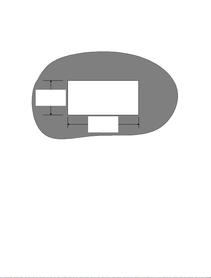
1. Prepare a mounting panel cutout by cutting a rectangular
hole (3.62” +0.02/-0.0” X 1.77” + 0.02/-0.0”) in the
desired location (see Figure following page). The
maximum panel thickness is 3/8 inches.
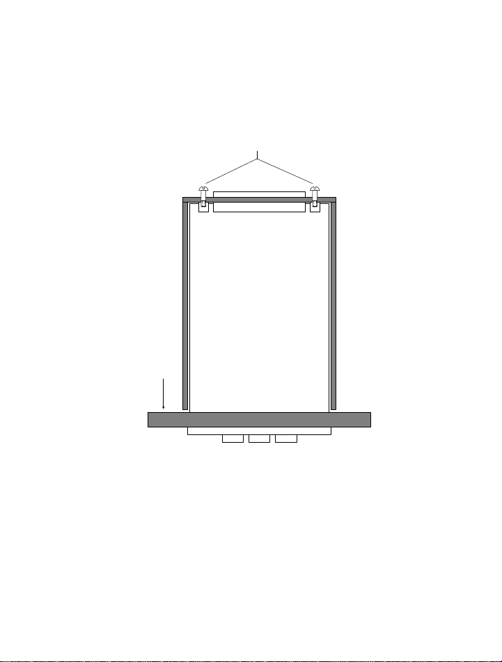
2. Remove the mounting bracket from the instrument
housing by removing the two screws on the rear of the
indicator..
3. Remove the pluggable terminal block located at the rear of
the unit and wire the input power and RS232 wires. If an
option board is installed in the indicator, remove the
connector and make the appropriate connections (refer
to diagrams).
WARNING!
Dangerous voltages are exposed at the screw
terminals. Always remove power before working in
this area for rewiring, disassembly, and all other
activities that involve proximity to electrical
3
Page 5
circuitry. Allow at least 10 minutes prior to
working on the unit.
PANEL CUTOUT
1.77 in.
+0.02/-0.0
3.62 in.
+0.02/-0.0
4. Install the indicator in the panel cutout from the
front side of the panel. Be sure the instrument is
right-side-up. See figure on following page.
5. Reinstall the mounting bracket on the indicator.
Tighten the bracket screws to achieve a snug fit
against the panel. Avoid distorting or cracking the
housing by not over- tightening the bracket screws.
4
Page 6
PANEL
BRACKET
SCREWS
INSIDE
CASE
5
Page 7
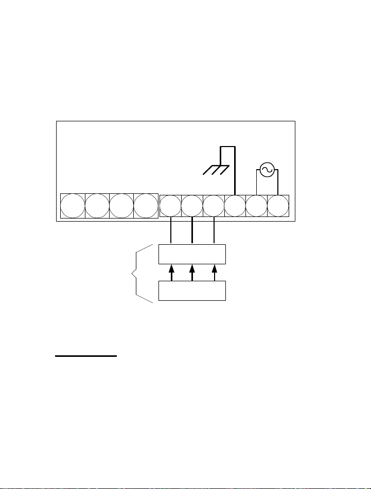
Single Channel Wiring
100/240VAC HOT
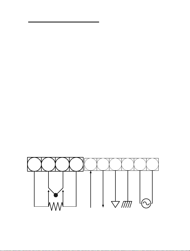
For easy installation, remove the pluggable terminal block
located at the rear of the unit. Connect the input power and
RS232 wires to the wire entry locations beneath and
perpendicular to the plug-in direction according to figure
below.
WARNING!
Dangerous voltages are exposed at the screw
terminals. Always remove power before working in
this area for rewiring, disassembly, and all other
activities that involve proximity to electrical
circuitry.
RTD - I
1
2 3 4 5 6 7 8 9 10
-V
+V
RTD + I
SERIAL RXD
SERIAL TXD
6
SERIAL COM
GND
NEUTRAL
Page 8
Three Wire RTDs
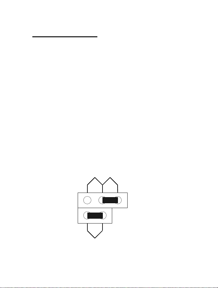
Note: All RTD units are shipped from the factory configured
for 4-wire RTDs unless otherwise requested. To enable the
unit to measure 3-wire RTDs, remove the electronics
assembly from the housing and complete the following steps.
If an option card is installed, remove the top and bottom
screws and carefully lift the option card from the main board
assembly.
Step 1. Remove the jumper located on the topside on the
main board from across pins labeled 4W and install it across
the pins labeled 3W.
Step 2. Place the jumper provided across the header labeled
ICOMP. This completes the configuration from 4-wire RTD
to 3-wire RTD.
4W 3W
ICOMP
7
Page 9
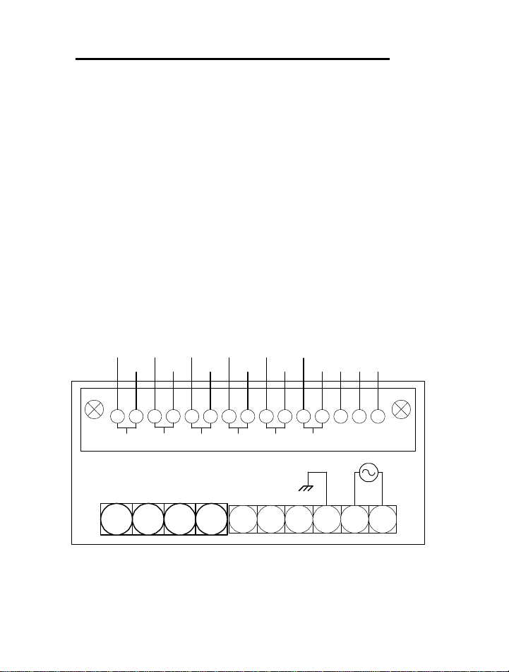
Thermocouple Multiple Input-Wiring
RELAY NC
The Multiple Input Option uses a quick disconnect terminal
block to facilitate wire installation and servicing. The
terminal block engages the printed circuit board (PCB)
fingers of the Multiple Input board which fits through the
upper slot located at the rear of the unit. The method of
attachment is the same as for a PCB edge connector: push on/
pull off. If desired you can use the two screws that are
provided for securing the connector to the instrument case.
Note that terminal numbers 13, 14 and 15 are provided for
limit relay contact access.
+V-V+V-V+V-V+V +V
CH1 CH2 CH3 CH4 CH5 CH6
NOT USED
-V -V -V
5 6 7 8 9 10
+V
9 10 11 12 13 14 151 2 4 5 6 7 83
8
COMMON
RELAY NO
Page 10
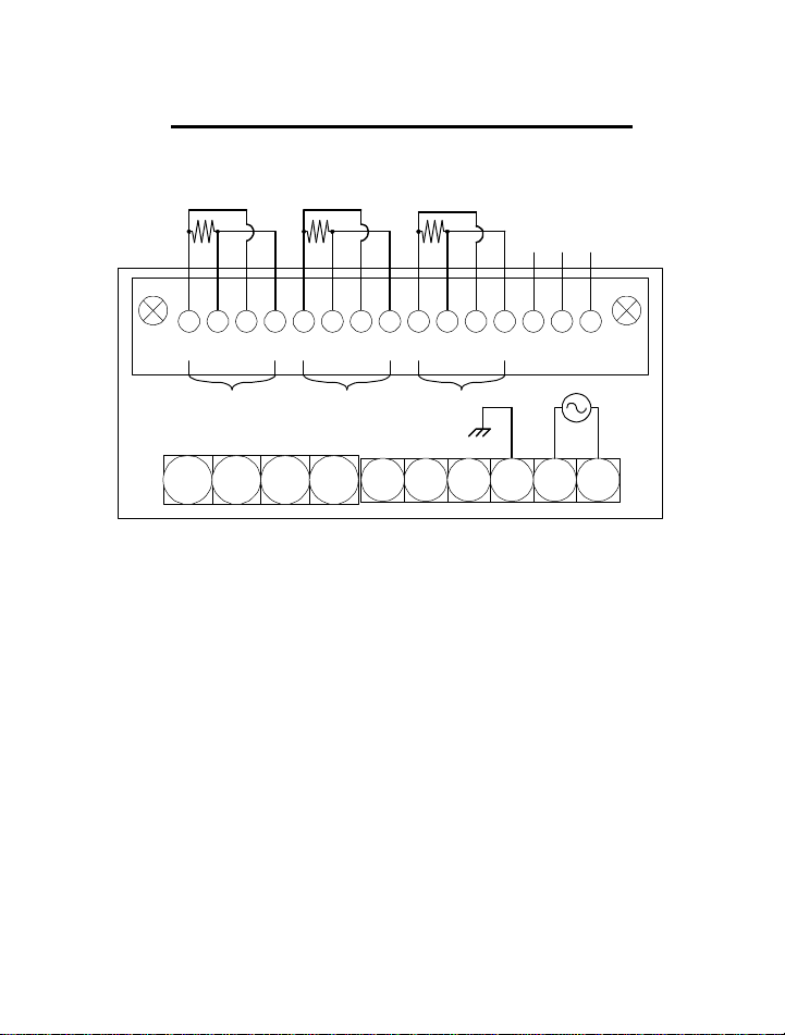
RTD 4-Wire Multiple Input-Wiring
RELAY NC
RELAY NO
COMMON
+V -v -I +V -V +I -I+I
CH1 CH2 CH3
NOT USED
5 6 7 8 9 10
9
+V -V +I -I
13 14 15
Page 11
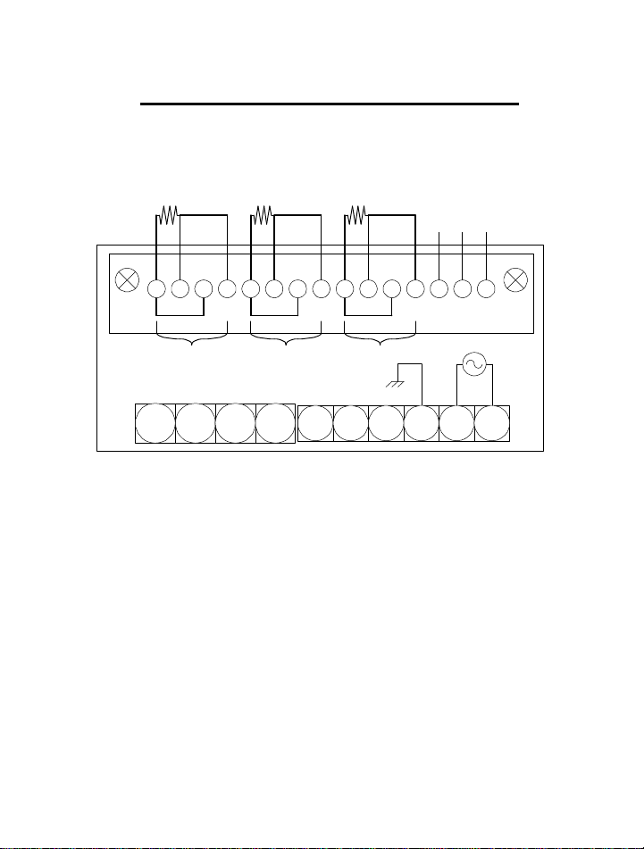
RTD 3-Wire Multiple Input-Wiring
RELAY NC
RELAY NO
COMMON
+V -v -I+I +V -V +I -I +V -V +I -I
CH1 CH2 CH3
NOT USED
5 6 7 8 9 10
10
13 14 15
Page 12
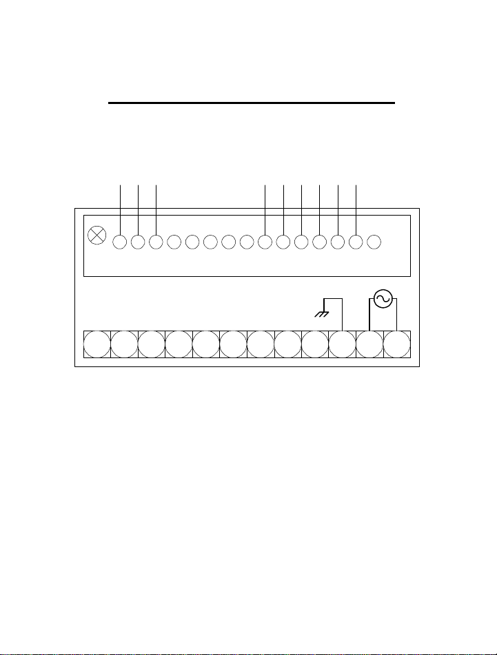
Analog Output/Dual Alarm Wiring
ALOG +V/-I
ALOG +I
ALOG -V
COM2
RELAY2 NC
9 10 11 12 13 14 151 2 4 5 6 7 83
1 2 3 4 5 6 7 8 9 10 11 12
COM1
RELAY1 NC
RELAY2 NO
RELAY1 NO
11
Page 13
Chapter 3
PGM
Operation
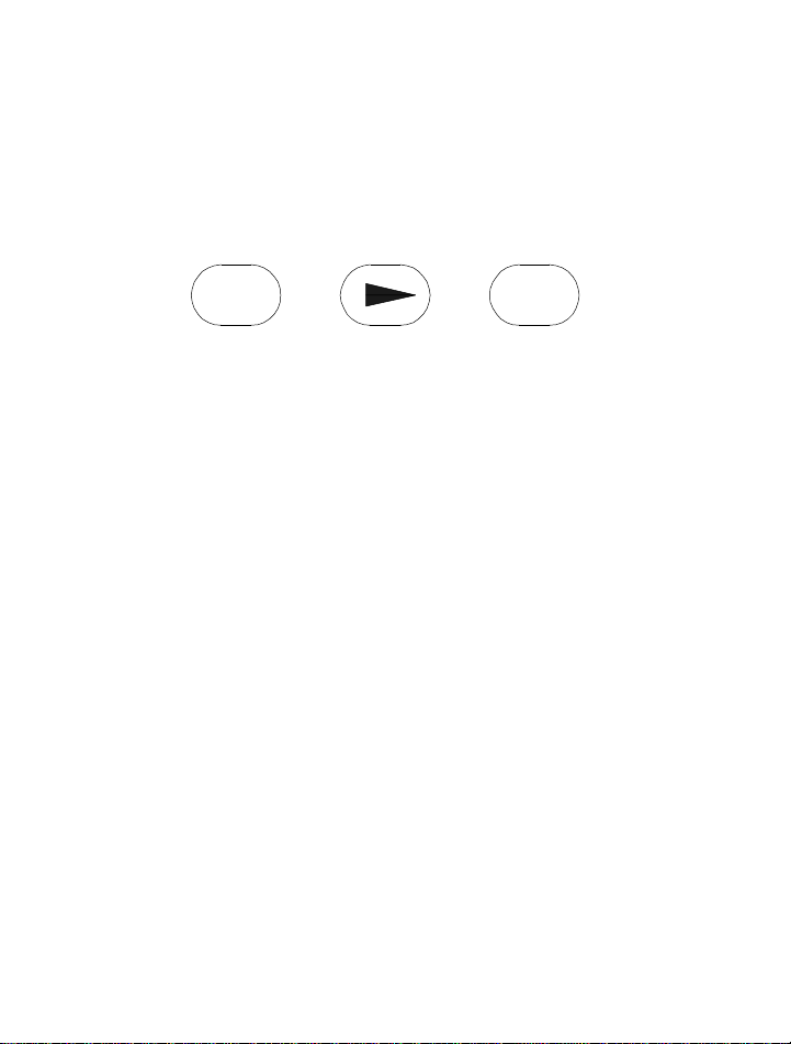
Your indicator is programmed by a series of menu driven
displays that are operated by three front panel pushbuttons;
Program-PGM, Arrow-∆, and Enter-ENT.
ENT
PROGRAM ARROW ENTER
Addressing the main menu items configures the indicator.
The indicator has a program lockout jumper located behind
the front panel lens. Removing the jumper will prevent any
front panel changes of the indicator programming. The
indicator may still be programmed via the computer interface.
When using the Series 5000 Viewer Software the front panel
keyboard is automatically disabled. The basic unit has three
main menu items that define the configuration of the
indicator and one calibration menu.
1. INPT: Sets up sensor type, °F/°C, and
1 deg/0.1 degree resolution.
2. MATH: Selection enables viewing of either
minimum or maximum value.
3. CAL: Used for calibration
.
12
Page 14

The following menu items are displayed only when the
appropriate option is installed-
5. ALM1/ALM2: Sets relay trip points to a
programmed value as well as other alarm
related parameters
6. AOUT: Programs the indicator to translate the
display to a proportional analog output signal
7. MULT: Configures indicator for multiple same
type input sensors
Pressing the PGM key allows you to access any of the menus
listed above by placing the indicator in program mode,
indicated by a ‘P’ lit to the right of the display. Placing the
indicator in PGM mode will prevent the indicator from
performing measurements. Any alarm monitoring will be
disabled.
If the PGM key is pressed anywhere within a menu,
the menu reverts to the previous menu level. Repeatedly
pressing the PGM key will return the indicator to the display
mode. Choices within a menu are viewed by pressing the
ARROW key. A menu item is selected by pressing the ENT
key for selection, or edited by pressing the ARROW key.
Generally, the ARROW key allows you to scroll horizontally
through a selection of choices while the ENT key enables you
to make selections and move down vertically to the next menu
item.
If the alarm option is installed and the alarm relays
13
Page 15

are set to unlatch manually (‘MAN'), relay #1 may be
unlatched by pressing and holding the ARROW key while
pressing the PGM key. Pressing and holding the ARROW
key while pressing ENT key will unlatch relay #2.
Note: Basic units shipped from the factory are configured
for type K thermocouple, °°F, 0.1 degree resolution.
Multiple Input models are shipped from the factory with a
5 second scan rate, channel 1 on, all alarms off with the
setpoint set LOW at 0000.
Dual Alarm/Analog Output models are shipped with both
alarms off, set for LOW and 0000. Deviation value set to
0000. Analog out is set to scale from 0°° to 1000° ° with
either 0-10VDC or 4-20Ma out.
Sensor Setup
Example: To select Type K thermocouple, °F, and 0.1°
resolution...
STEP 1. Press the PGM button. PGM will appear on the
display. The °F/°C LED will change to P (for ‘Program
Mode).
STEP 2. Press the Arrow key until INPT appears on the
display. Open the Input Menu for programming by pressing
the ENT key. One of the seven thermocouple types and two
RTD types will appear on the display (J,K,E,T,R,S,392,385).
14
Page 16

Scroll through the various sensor types by pressing the Arrow
key until a “K” appears on the display. Press the ENT key to
select K type thermocouple.
STEP 3. An F or C will appear. Pressing the Arrow key
repeatedly will cause C and F to alternate on the display.
With F on the display, select degrees F by pressing the ENT
key. DCPT will appear. The Arrow key allows you to toggle
back and forth between 0.1 and 1.0 degree resolutions.
STEP 4. To select 0.1° resolution, with 0.1 on the display
press the ENT key. At this point the display will show the
MATH menu item*. To open the MATH menu for
programming, press the ENT key. To go back to the mode,
press PGM key. In order to scroll through the various menu
items press the Arrow key.
*MATH functions are available on units with Multi-
channel option installed only through the Doric
5000 Viewer Software.
Math Function Setup
Example: View the maximum temperature value recorded.
Note: A running record is kept of the minimum, and
maximum values of temperature. Nothing is
required to initiate this recording. These values are
15
Page 17

there whenever you need them. You can display the
Minimum or Maximum value by following the steps
below.
STEP 1. With the MATH menu on the display, open this
menu item by pressing the ENT key. MIN is on the display.
STEP 2. Press the Arrow key to toggle between MIN and
MAX. When the display shows MAX, press the ENT key and
the display will now indicate the maximum value. The
MIN/MAX memory may be reset at this point by pressing the
Arrow key. With CLR (CLEAR) on the display, press ENT.
His will restart the recording process. To go back to the
current temperature display, press the PGM button and the
display will indicate the current temperature reading.
Multiple Input
The multiple input option will enable the user to
monitor up to 6 same type thermocouple inputs, or 3 threewire/four-wire RTDs. Any number of channels can be
selected manually or scanned automatically. Alarm limits
may be assigned to individual channels. One NO/NC 5 amp
115VAC relay contact is available for high or low alarm limit
programming.
Two modes are selectable for the multiple input
option- manual (MAN), and automatic (AUTO). MAN mode
allows the user to view a selected channel. Pressing the arrow
key advances the display to the next active channel. The
channel number is indicated by a .4” green LED located in
the upper left-hand corner of the display. To begin scanning,
16
Page 18

select AUTO. The scan rate is selectable in one-second
increments between 5 and 20 seconds. The display readout
will then sequentially show the temperature of the active
channels. Any number of channels may be selected for
scanning.
If an alarm limit is exceeded on any displayed
channel, the display will flash, and the relay contact will
latch. The relay will remain latched until the alarm condition
clears. In scanning mode the display will flash on the alarm
channel as it scans.
By using the Doric Series 5000 Viewer, the Series
5000 can log and send multiple channel data through the
serial port making it a miniature datalogger.
Dual Alarm
The alarm card has two 5 amp/115VAC relays for high, low
or deviation setpoints. The alarm card is available by itself or
with analog output (either voltage or current). Relay setpoints
are programmed through the front panel menu or via the
serial port. An alarm limit may be disabled within the alarm
menu by selecting OFF at the first menu prompt. If OFF is
selected the display will return to the next main menu item
for further programming. If ON is selected the menu proceeds
down through the alarm menu for further setpoint
programming.
The relays can be operated in MAN or AUTO mode.
In AUTO mode, the relay unlatches by itself once the alarm
limit is no longer exceeded.
In MAN mode the relay is reset manually. However,
the display continues to flash until the alarm limit is no
longer exceeded.
17
Page 19

- Pressing and holding the Arrow key and pressing
the PGM key resets Relay 1 (ALM1).
- Pressing and holding the Arrow key and pressing
the ENT key resets Relay 2 (ALM2)
Note: When the Viewer Software is being used, the
front panel keys are disabled. Relays must therefore
be reset using the Unlatch buttons on the Viewer
control panel.
When HIGH is selected, a temperature greater than
or equal to the limit value will cause an alarm. When LOW is
selected, a temperature less than or equal to the limit value
will cause an alarm.
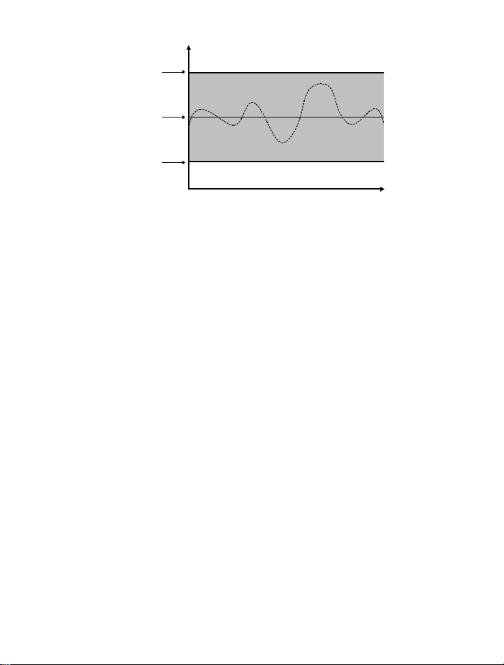
Using Deviation
Deviation allows the user to assign alarm limits above and
below the normal operating points of a process. If the
temperature remains within the high and low deviation
setpoints no alarm occurs. If the temperature equals or
exceeds either the high or low deviation limits an alarm
occurs. Hysteresis and delay are also programmable for
deviation setpoints (see following explanations). Deviation
allows the user to assign two setpoints per alarm relay for a
total of four alarm setpoints per alarm option (See drawing
below). This could be useful for indicating a warning
condition with one relay and an emergency condition for the
other relay.
18
Page 20
Hysteresis
TIME
upper
deviation
limit
lower
deviation
limit
operating
temp
Hysteresis or deadband is used to delay the unlatching of a
tripped relay. Hysteresis may be selected within the alarm
menu as either ON or OFF. Hysteresis is selectable from 0-99
degrees in 1° increments. For example, a limit with a
hysteresis value of 5 assigned to it means that the display
value must return 5° below the alarm setpoint before the
alarm condition is cleared (the relay resets). Hysteresis
assumes negative values for HIGH limits and positive values
for LOW limits.
Delay
Programming the meter for alarm delay prevents an alarm
trip for a specified period of time (0-9 seconds). An alarm
delay would be used whenever an unstable or noisy input
signal is present. By filtering out short duration alarm
conditions, alarm delay prevents unnecessary alarms from
occurring.
19
Page 21

Analog Output
The analog output option translates the indicators’ display
reading to a proportional analog output signal. There are two
versions of the analog output option, either 0-10VDC or 420ma. Both voltage and current outputs are scaleable within
their ranges and are similarly programmed. Note that the
analog output is active only in the display mode. As soon as
the indicator is put in the program mode, indicated by a P in
the lower right hand corner of the display, the output goes to
its zero output value. The display reading can be scaled from
-999 to +9999, which enables the user to use only a portion of
the full scale if necessary.
Analog Output Setup
Example1: Program the indicator to output 4.0 ma at 32.0°
F and 20.0 ma at 500° F...
STEP 1. Press the PGM button. PGM will appear on the
display. The °F/°C LED will change to P (for ‘Program
Mode).
STEP 2. Press the Arrow key until ALOG appears on the
display. Open the ALOG Menu for programming by pressing
the ENT key.
STEP 3. A LOW or HIGH will appear. Pressing the Arrow
key repeatedly will cause LOW and HIGH to alternate on the
display. With LOW on the display, select LOW by pressing
the ENT key. The digits 0000 will appear with the left most
20
Page 22

digit flashing. With the ARROW key select the number 0.
Press ENT. The second digit will flash. Enter 0 again with
the ARROW key. Continue on until 0032 is on the display
with the 2 flashing. Press ENT.
STEP 4. HIGH will appear on the display. Press ENT. Set
the first digit to 0 by using the ARROW button. Set the
second digit to 5 and so on until 0500 is on the display. With
the farthest digit to the right flashing, press ENT. The next
menu item appears.
Example2: Program the indicator to output 0.0 VDC at
0°F and 5VDC at 1000°F.
Note: The analog output may be scaled to output
various voltages such as 0-2VDC, 1-5VDC etc.
STEP 1. Press the PGM button. PGM will appear on the
display. The °F/°C LED will change to P (for ‘Program
Mode).
STEP 2. Press the Arrow key until ALOG appears on the
display. Open the ALOG Menu for programming by pressing
the ENT key.
STEP 3. A LOW or HIGH will appear. Pressing the Arrow
key repeatedly will cause LOW and HIGH to alternate on the
display. With LOW on the display, select LOW by pressing
the ENT key. The digits 0000 will appear with the left most
digit flashing. With the ARROW key select the number 0.
21
Page 23

Press ENT. The second digit will flash. Enter 0 again with
the ARROW key. Continue on until 0000 is on the display
with the 0 flashing. Press ENT.
STEP 4. HIGH will appear on the display. Press ENT. Set
the first digit to 2 by using the ARROW button. Set the
second digit to 0 and so on until 2000 is on the display. With
the farthest digit to the right flashing, press ENT. The next
menu item appears.
22
Page 24

Chapter 4
Calibration
Thermocouple Type: Single Channel
Equipment Required:
1. Precision voltage source with a resolution to 1uV and an
accuracy of ±0.01% or ±2.0uV.
2. Interconnecting copper wire from the DC source to the
indicator.
3. Trimmer adjusting tool.
WARNING!-Dangerous
voltages exist on charged capacitors even
after unit is de-energized. Allow 5 minutes
of discharge time before removing unit
from case.
STEP 1. Remove power and snap off the front panel lens.
Leave the keypad attached to the display board, as it will be
required to enter the calibration menu. Remove the rear
pluggable connector from the rear of the indicator and slide
23
Page 25
the main board electronics out of the case from the front.
(Gently lift the display board above the catch located on the
bottom of the inside of the plastic housing while pushing on
the rear male connector on the rear of the main board
assembly.)
STEP 2. Observing polarity, connect the DC voltage source
to the thermocouple inputs according to the wiring diagram
located on the plastic housing. With the power OFF, plug in
the wiring connector to the rear of the main board. Turn
power on and allow at least a 10-minute warm-up.
STEP 3. Enter the program mode by pressing the PGM key
and then the ENT key. The INPT menu appears. Press the
Arrow key until the CAL menu appears. Press ENT. Input
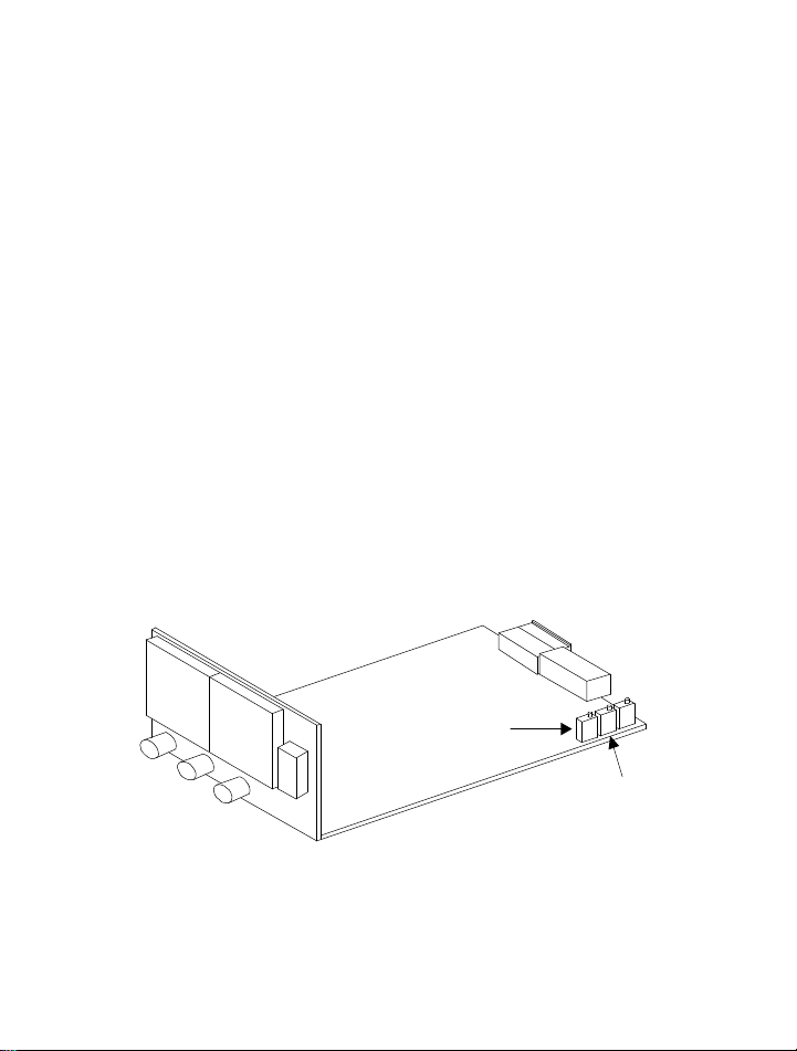
0.00 mV and adjust the ZERO potentiometer RV201 (see
figure below) for a display of 0.0 ± 0.1.
24
SPAN
ZERO
Page 26

NOTE: Display readings take up to 10 seconds to
respond to changes in the zero and span pots.
STEP 4. Adjust the voltage source output to 39.000 mV.
Adjust the SPAN potentiometer RV203 for a display reading
of 560.0 ±0.1. Press PGM to exit the calibration mode. Turn
the indicator power OFF.
NOTE: The reference junction adjustment is factory
set. However if after performing the zero and span
calibration the unit is not accurate within factory
specifications, an adjustment of the reference
junction may be necessary.
STEP 5. Reference Junction Adjust With the power
turned OFF, remove the copper wires from the +V and -V
input connections and connect a thermocouple simulator with
K thermocouple wire, connect the negative lead (red) to
terminal 2 and the positive lead to terminal 3.
STEP 6. Turn power on and allow several minutes warm
up. Program the indicator for K thermocouple type, °F (see
Chap.3 Sensor Setup). Adjust the input source for an output
of 32.0°F and adjust RV202 for a display reading of 32.0°F.
Allow at least 15 seconds between adjustments. This
completes the thermocouple type calibration procedure.
25
Page 27

RTD Type:
Equipment Required:
1. Precision resistance decade box with a resolution of 0.01Ω
and an accuracy of ±0.02%.
2. Interconnecting copper wire from the resistance source to
the indicator.
3. Trimmer adjusting tool.
WARNING!-dangerous voltages exist on
charged capacitors even after unit is deenergized. Allow 5 minutes of discharge
time before removing unit from case.
STEP 1. Remove power and snap off the front panel lens.
Leave the keypad attached to the display board as it will be
require to enter the calibration menu. Remove the rear
pluggable connector from the rear of the indicator and slide
the main board electronics out of the case from the front.
(Gently lift the display board above the catch located on the
bottom of the inside of the plastic housing while pushing on
the rear male connector on the rear of the main board
assembly.)
STEP 2. Observing polarity, connect the decade box to the
RTD input (+V, -V, +I, -I) to the pluggable connector RTD
26
Page 28

inputs according to the wiring diagram located on the plastic
housing. With the power OFF, plug in the wiring connector
to the rear of the main board. Turn power on and allow at
least a 10-minute warm-up.
STEP 3. Enter the program mode by pressing the PGM key
and then the ENT key. Press the ARROW key to scroll
through to the CAL menu. Press ENT. Adjust the zero
potentiometer RV201 (see FIG 4.1) for a display of 0.0 ± 0.1.
NOTE: Display readings take up to 10 seconds to
respond to changes in the zero and span pots.
STEP 5. Adjust the decade box to 265.00Ω. Adjust the
SPAN pot potentiometer RV203 for a display reading of
543.8 ±0.1. Press PGM to exit the calibration mode.
Turn the indicator power OFF, re-install the main board back
into the case. Apply power to the instrument and reset the
input type to the desired sensor.
Analog Output Current :
NOTE: The Analog Output Current option is
calibrated from the factory to output 20.00 ma with
1000° on the display and 4.00 ma with 0.0° on the
display. The output may be trimmed to meet your
specific application.
27
Page 29

Equipment Required:
1. Precision current meter with 0.1% accuracy and 10uA
resolution.
2. Interconnecting copper wire from the DC current source
to the indicator, +I to terminal 3 and –I to terminal 1 of
the 15 position terminal block located at the rear of the
unit..
3. Trimmer adjusting tool.
4.Thermocouple simulator for Thermocouple units or
Precision resistance decade box with a resolution of 0.01Ω
and an accuracy of ±0.02%.
STEP 1. Remove power and snap off the front panel lens.
Leave the keypad attached to the display board as it will be
required to enter the programming menu.
STEP 2. Apply power to the unit and allow at least a 10
minute warm-up. Program the unit for the appropriate sensor
type.
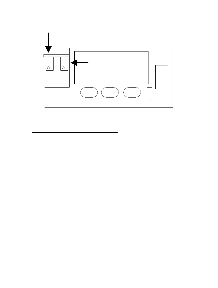
STEP 3. With the input set to correspond with the LOW
input, adjust the zero pot to read 4.00ma on the DC Ammeter.
STEP 4. With the input set to correspond with the HIGH or
full scale input, adjust the full scale potentiometer to read
20.00ma on the DC Ammeter.
28
Page 30
FULL SCALE
ZERO
Analog Output Voltage:
NOTE: The Analog Output Voltage option is
calibrated from the factory to output 10.00 VDC
with 1000° on the display and 0.00 VDC with 0.0°
on the display. The output may be trimmed to meet
your specific application.
Equipment Required:
1. Precision voltage meter with 0.1% accuracy and
10mVDC resolution.
29
Page 31

2. Interconnecting copper wire from the DC current source
to the indicator, -V to terminal 3 and +V to terminal 1 of
the 15 position terminal block located at the rear of the
unit..
3. Trimmer adjusting tool.
4.Thermocouple simulator for Thermocouple units or
Precision resistance decade box with a resolution of 0.01Ω
and an accuracy of ±0.02%.
STEP 1. Remove power and snap off the front panel lens.
Leave the keypad attached to the display board as it will be
required to enter the programming menu.
STEP 2. Apply power to the unit and allow at least a 10
minute warm-up. Program the unit for the appropriate sensor
type.
STEP 3. With the input set to correspond with the LOW
input, adjust the zero pot to read 0.00VDC on the DC
voltmeter.
STEP 4. With the input set to correspond with the HIGH or
full scale input, adjust the full scale potentiometer to read
10.00VDC on the DC Voltmeter.
30
Page 32

Chapter 5
Doric Series 5000 Viewer Overview
Series 5000 Series indicators interface to PC compatible
computers through the RS232 port. Configuration of RS232
is accomplished simply by selection of COM port. Baud rate
and communications parameters are automatically
configured. All Series 5000 series features (Alarm Status,
Input Identification, Min/Max Indication, Time Tagged
Readings) are presented with a simulated LED display in an
on-screen control panel format.
The internal indicator clock is automatically set to your
computers time and date each time you launch the Series
5000 Viewer Software. The Doric Series 5000 Viewer
enhances the Series 5000 series indicators by adding large
volume data logging capability. Data is logged to formatted
ASCII text files that are compatible with most modern
spreadsheet applications. Data can be logged in increments
from 1 minute to 24 hours.
Minimum PC requirements
486 Processor minimum (Pentium recommended)
Windows 95/NT
16 Mb ram (32 recommended)
Mouse
3.5 inch disk drive
9 or 25 pin Serial Communications Port
31
Page 33

File Formats
Space delimited ASCII text
DATE TIME AM/PM CHAN TEMP °F/°C
Installation
1. Connect a communications cable between your PC and
the meter according to the diagram next page.
2. Start Windows 95.
3. Insert disk into drive A or (B).
4. In Windows 95 chose RUN from the Start menu.
5. Type A:\setup (or B:\setup) and click OK.
5. The Installation Wizard will guide you through the
remainder of the installation procedure.
After launching the program, your instrument and PC should
communicate. If your unit is not communicating ensure the
serial communications cable is wired correctly and the
proper COM port is selected.
Note: Once communications is established, the PC
has control of the instrument and the front panel
keys become non-functional. In order to regain
control of the front panel the software program
32
Page 34
must be closed. If the configuration of the unit
has changed e.g. thermocouple type, the software
will read and reconfigure itself to match the
instrument.
REAR VIEW
Rx Tx Com
5 6 7 8 9 101 2 3 4
9 PIN CONN
Rx
53 2
72 3
Com
25 PIN CONN
Computer
side
RS232
Tx
Operation
Alarms- A small box located to the left of the alarm box
indicates alarm status. An L inside the box indicates a low
alarm limit and an H indicates a high alarm limit. A grey box
with no letter indicates an inactive alarm.
33
Page 35

- A green box indicates an active alarm not
in an alarm condition
- A flashing red box indicates that the channel is
in an alarm condition
If an alarm condition occurs while the Viewer window is
minimized, the window will reopen automatically to alert the
user that an alarm limit has been exeeded.
Multiple Input Models
- When in MANUAL mode, the instrument can
only monitor the selected channel. The selected
channel and its’ ID is displayed under the
simulated display
- The next active channel may be viewed by
pressing the NEXT button located beneath and
to the left of the simulated display
- If a selected channel alarms and the next
channel is selected, the flashing red indicator
turns yellow. This indicates that this channel
was in an alarm condition when last viewed.
Logging data
To create a file of logged data, open the preference menu by
clicking the Preferences button located in the upper right
hand corner of the Viewer window. Open the LOG menu by
clicking the LOG button. You may name your file any
acceptable Windows 95 name. The default file extension is
.dat. The path for your log file will be shown on the main
control panel window. Select the interval (between 0-24
hours at 1 minute increments.) at which logs will be taken.
34
Page 36

Close the log preference window. To begin logging, click the
button on the main control panel labeled OFF. The button
will change to ON and the unit will now begin logging.
35
Page 37

Chapter 6
General Electrical Specifications
Repeatability +/- 1 Count (single channel only)
Stability with temperature
Zero: 1uV/° C
Span: .01%
Thermocouple Reference Junction Internal, automatic, 0.03
degrees C/degrees C, 5 °C to 45 °C.
Break Detection Upscale ≈ 50nA unit displays OL.
Stability with Time .8°/year
Noise Rejection
NMRR: 60dB @ 50/60 Hz
CMRR: 120dB @ 50/60 Hz (+/-0.1Hz with 250Ω
unbalance)
Overload Protection
Power leads to ground: (1500VDC or VAC RMS)
Across inputs, for one minute:
T/C up to 250VDC or VAC, V+ to V-
36
Page 38

Input Impedance
Thermocouple: 20MΩ, exclusive of break detect
current effects
RTD: 16.9kΩ, V+ input to I input
RTD Lead Wire Error
At 150uA excitation current: 40mΩ/Ω of equal
resistance in V+ and V- leads,1Ω of inbalance in
V+ or V- leads
Point Update Rate
2 per second nominal (1° readings)
1 per second nominal (.1° readings)
Display
4 Digit, 14-segment red or green .56 in. height
LED plus 1 .4 in green °F/°C LED
Enviornmental Ranges
Operating: 0°C to 50°C
Storage: -40°C to +65°C
Humidity: ≤80%RH non-condensing
Multi-input Option Accuracy
Add ±1.0°C/2°F to instrument accuracy specification
from 60° Το 80°F
37
Page 39
Alarm Relay Contact Rating
5A@ 120VAC(non-inductive load) Form C
Power 100-240VAC (±10%), 50-400Hz, switching power
supply
Accuracy Specification ± 1 digit
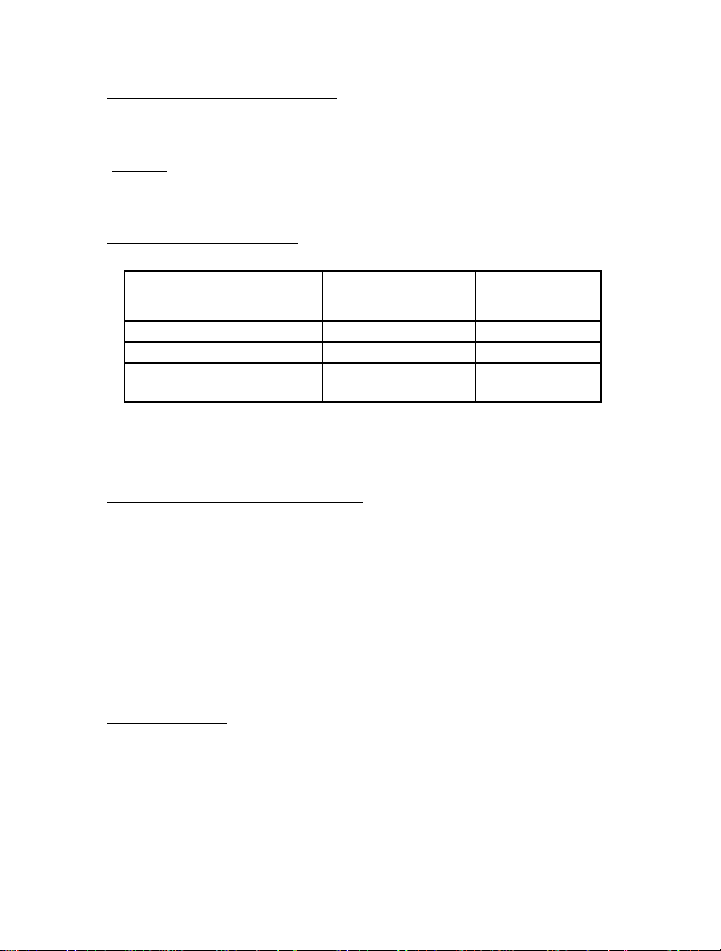
INPUT TYPE
1°° Resolution 0.1°°
Resolution
J,K,T,E thermocouples
R and S thermocouples
PT100a .00385,
PT100a .00392 RTD
1° plus 0.03% rdg 0.5°C or 0.9°F
1° plus 0.03% rdg
1° plus 0.03% rdg 0.5°C or 0.9°F
1 DEG ONLY
*Accuracy percentage of reading ±1 digit
RS232 Serial Communications (Standard)
Type: full-duplex voltage, isolated from ground to 500VAC.
Complete configuration set-up and message display
capability, programmable to transmit current display, set
1°/0.1°resolution, thermocouple type, F°/C° plus alarm status
and scanning channel indication in ASCI II code. 9600 bps 8
bits no parity 1 stop bit. Isolation: Isolated between input and
internal circuit to 500VAC
Analog Output (Option)
0-10VDC (load current 2ma maximum)
4-20mADC (load resistance 300Ω maximum)
Accuracy: ±0.25% full scale of display value
Resolution: Approximately .0125 Full scale
38
Page 40

Isolation: Isolated between input and internal circuit
to 500VAC.
39
 Loading...