

Page 1

Model 473
CALIBRATION PROCEDURE
3.1 Equipment Required:
4-1/2 digit, digital voltmeter
Precision millivolt/milliamp source:
Resolution, 1 V/ A; accuracy + .01% (+ 2 V)
Recirculating ice bath, 0.00 °C + .05 °C
Type K thermocouple wire
Copper hookup wire
Potentiometer adjusting tool
Refer to Figure 3-1 for locations of pot adjustments and testpoints.
3.1.1 Millivolt Calibration
a. Remove battery from instrument (refer to 2.4.1). Remove bottom case half from
printed circuit board assemblies by extracting three screws from case bottom and one
screw holding wrist strap lug. Remove top case half from printed circuit board
assemblies by extracting screw on clad side of Analog Board between output controls.
Re-connect battery to connector.
b. Measure voltage at TP-8 (+) on Display Board (top board) with DVM common (-) at
TP-2 (cathode of CR1) on Analog Board (bottom board). Voltage at TP-8 should be
between 3.680-3.72V (pin 4 of p7). If measured voltage is outside of range adjust R9
on Analog Board for DVM reading at TP-8 of 3.695 V.
c. Set instrument to indicator mode, mV input.
d. Connect precision mV/mA calibrator source to T/C input observing proper polarity.
e. Adjust source output to 0.000 mV (short).
f. Select high resolution display (.00 mV). Display should read .00 with flashing minus
sign. Turn R21 clockwise: display should read .00, .01, .02, .03. Turn R21
counterclockwise: display should read .03, .02, .01, .00, -.00, -.01, -.02, -.03. Adjust
R21 for display reading of .00 with flashing minus sign. If reading is not stable, R26
on the Analog Board may need adjusting (normally adjusted near center).
g. Adjust source output to –7.000 mV.
h. Adjust R28 on Analog Board for an exact display reading of –7.00 mV.
i. Adjust source output to 0.00 mV, check zero reading and adjust R21 on Display
board as required for correct (.00) reading.
Page 2

j. Adjust source output to +27.000 mV.
k. Adjust R9 on Analog Board for an exact display reading of 27.00 mV.
l. Repeat steps 3.1.1g through 3.1.1.k as required until no further adjustment is required
for correct display readings.
m. Switch instrument to low resolution display (.0) and verify display readings of –7.0
mV, 0.0 mV, and 27.0 mV with an input of –7.00 mV, 0.000 mV, and 27.000 mV
respectively.
n. Perform temperature calibration as outlined in 3.1.2.
3.1.2 Temperature Calibration
This procedure required a recirculating ice bath and a Type K thermocouple probe and a
precision millivolt/microvolt source. The probe is constructed as follows: With a
suitable length of type K thermocouple wire and copper hookup wire, form functions
between each thermocouple wire (Hi and Lo) with a length of copper wire. Electrically
isolate these junctions and insert both junctions in a recirculating ice bath. The
calibration setup is shown in Figure 3-2.
a. Set instrument to indicator mode, Type K range, 0.1 resolution, °F scale.
b. Observing proper polarity, connect the thermocouple wires from the ice bath to the
instrument T/C input.
c. Observing proper polarity, connect the copper wires from the ice bath to the calibrator
source.
d. Adjust source output to 0.000 mV (short). Allow 15 minutes for stabilization.
e. Adjust R6 on Analog Board for display reading of 32.0 °F.
f. Adjust source to –4.513 mV.
g. Adjust R28 on Analog board for a display reading of –209.0 ° F.
h. Recheck display with zero input. Adjust R6 as required for a display reading of 32.0
°F.
i. Adjust source output to +7.848 mV.
j. Adjust R9 on Analog board for a display reading of 379.0 ° F.
k. Repeat steps 3.1.2.2f through 3.1.2.2.j until no further adjustments are required for
correct display readings.
l. Set instrument to indicator mode, mV input
m. Check the display reading with the following inputs: -7.000mV (-7.00 mV display),
0.000 mV (.00 mV display), +27.00 mV display). All readings should be within a
tolerance of + .01. If not the entire calibration procedure must be repeated.
n. Perform mA input calibration as outlined in 3.1.3 next.
Page 3

3.1.3 mA Input Calibration
a. Observing proper polarity, connect precision mA source to mA input jacks of
instrument.
b. Set instrument to mA input mode.
c. Set mA A/B switch to “A” position.
d. Adjust source output to 0.000 mA.
e. Adjust R5 on Display board for a display reading of .00 mA.
f. Adjust source output to 25.000 mA
g. Adjust R20 on Analog board for a display reading of 25.00 mA.
h. Repeat steps 3.1.3 through 3.1.3g until no further adjustments are required for correct
display readings.
i. Carefully reassemble instruments
CALIBRATION COMPLETED
Page 4
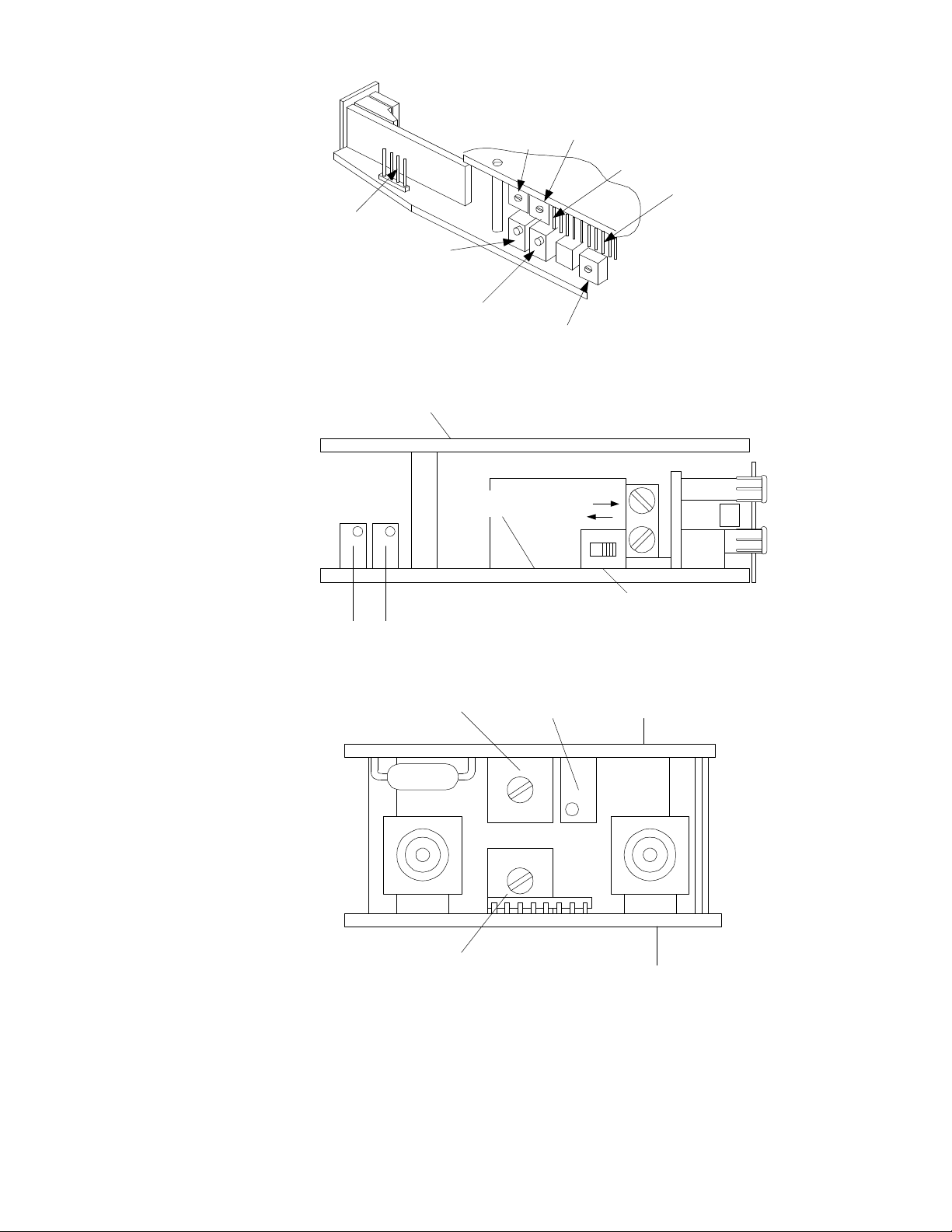
TP-2
R6
R28
DISPLAY BOARD
R19
R26
PIN 16
TP-8
R26
R9 R20
ANALOG BOARD
RIGHT SIDE
R5
R21
A
B
mA A/B SWITCH
DISPLAY BOARD
R44
ANALOG BOARD
FIGURE 3-1 POTENTIOMETER ADJUSTMENT/
TESTPOINT LOCATIONS
 Loading...