

Page 1
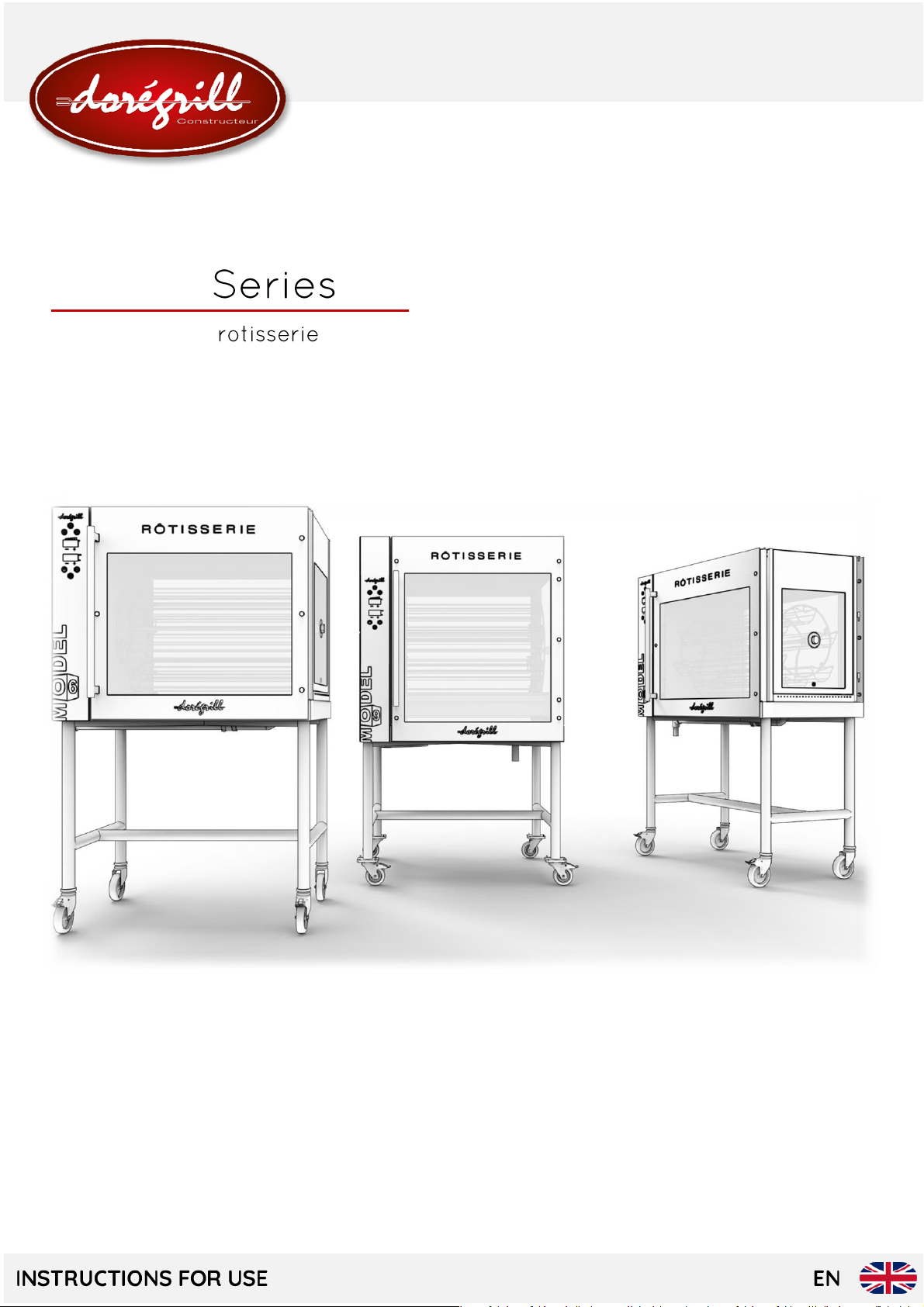
MODEL
Baskets-roast
Page 2

Page 3
TABLE OF C ONTENTS
TECHNICAL DESCRIPTION
3.1 General description
3.2 General components
3.3 Control panel
3.4 Rotisserie Dimensions
3.5 Technical Data
3.6 Intended use
3.7 Electrical diagram
4.1 General instructions
4.2 Installation
4.3 Electrical Connection
MAINTENANCE
5.1 Disassembly for Cleaning
5.2 Longevity of Armored Elements
5.3 Automatic Cleaning Cycle
MAIN CAUSES OF TEMPERED GLASS BREAKAGE
6.1 Thermal Shock
6.2 Blows to the glass
6.3 Handling
TECHNICAL SPECIFICATIONS
MAINTENANCE / AFTER-SALES SERVICE
8.1 Fault finding
Page 4
8.2 Specific repairs
8.2.1 Changing a Bulb ..................................................................................................................................... 21
8.2.2 Opening of the technical housing ..................................................................................................... 21
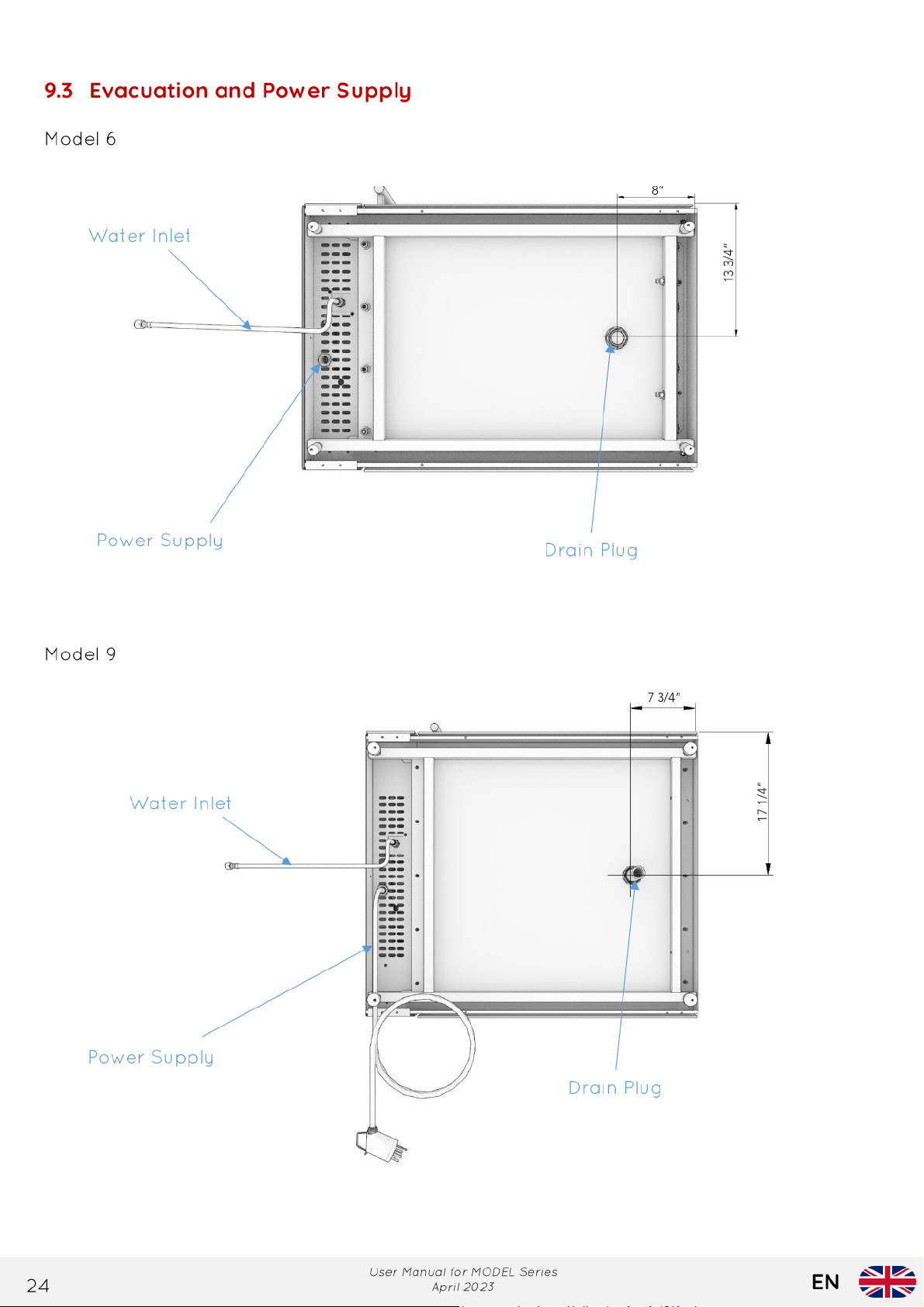
9.3
Page 5
GENERAL INFORMATION
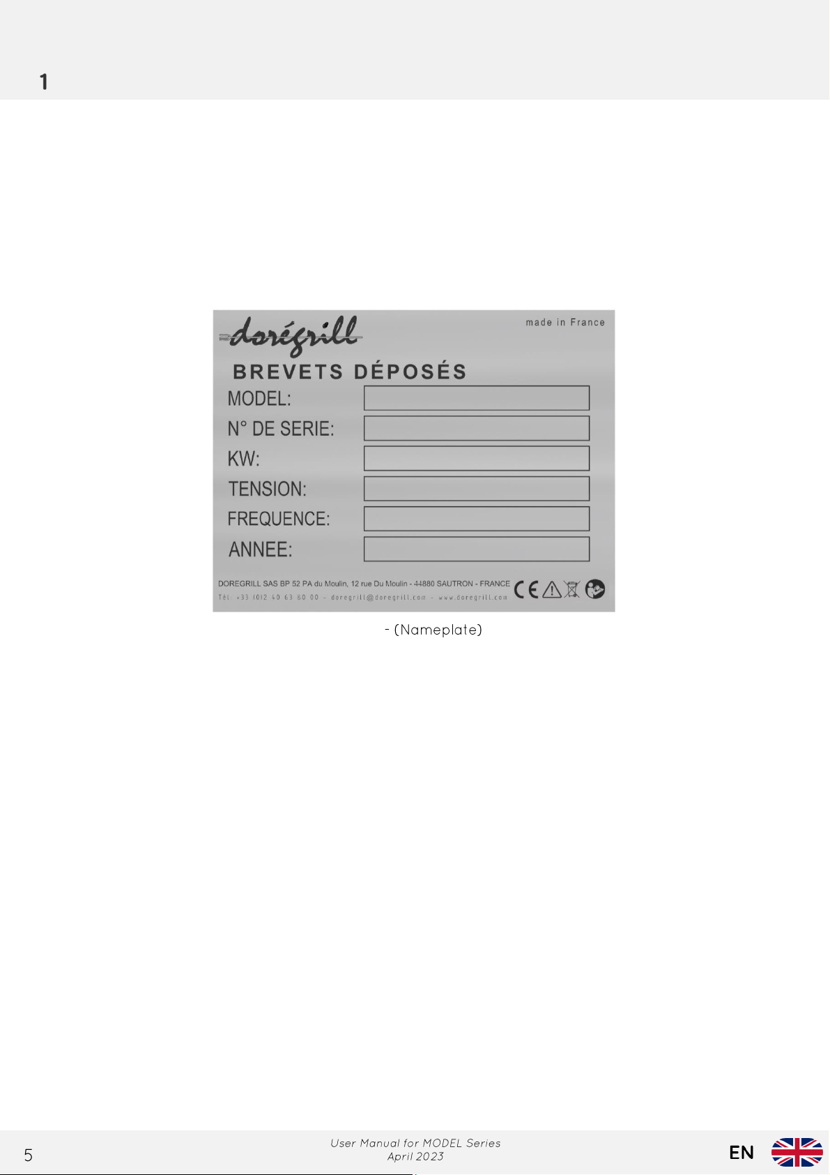
1.1 Marking
This equipment complies with the applicable European directives. Therefore, the CE logo appears
on the nameplate and a declaration of conformity is attached to this manual.
- Manufacturer's name and address - Serial number
- CE marking - Electrical voltage and frequency
- Equipment model - Year of manufacture
- Electrical power
This plate is attached to the left side of the rotisserie at the bottom of the technical chest closure
panel.
1.2 Importance of the manual
This manual aims to provide installers and users of DOREGRILL equipment with all the necessary
information for optimal use, to extend its lifespan through regular and appropriate maintenance,
to address minor incidents and breakdowns that often do not require the intervention of a
specialist, and to avoid any risk of injury to its users by following the warnings and
recommendations.
The time and attention devoted to reading this manual will be largely compensated for by the
knowledge gained, and the risks of sometimes irreparable damage that have been avoided.
Integral part of our rotisseries, this manual, valid for MODEL 6 and MODEL 9 models, must be
available to its operators.
The manufacturer is not responsible for any damages to persons, animals, or property due to the
improper use of the equipment or non-compliance with the rules described in this manual.
Fig. 1
Page 6
1.3 W arranty
To avoid the risk of serious burns, this appliance MUST be placed against a wall or
Rotisserie (safety barriers, insulated w all, etc).
IMPORTANT: This device is for professional use. To avoid any danger, its operation
country of installation.
should be carried out by qualified personnel. Parts that have been protected by
the manufacturer or its representative should not be handled by the installer or
the user. It must be installed in accordance with the regulations in force in the
1.4 Reserved rights
1.5 General precautions
IMPORTANT: Handling and/or replacing components with non-original parts w ill
void the warranty and release the manufacturer from any liability.
the store's façade. The back of the Rotisserie does not provide a visual indication
of its function and the potential danger posed by extreme temperatures. In case
it's impossible to position the machine along the wall, the user must implement all
necessary measures to protect pedestrians from potential contact with the
Page 7
Transport and handling
2.1 Transport and delivery
2.2 Unpacking and handling
Page 8

TECHNICAL DESCRIPTION
3.1 General description
The MODEL 6 and MODEL 9 series are mounted on wheeled carts, two of which are equipped with
brakes.
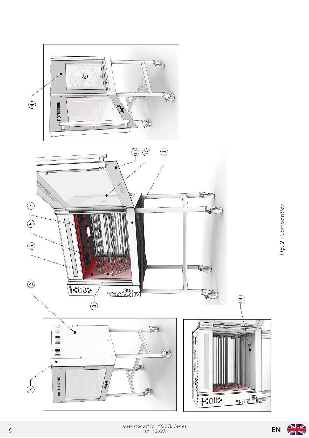
The rotisseries consist of
(Fig. 2)
:
- Made of brushed stainless steel, it features a structure (base 1, ceiling 2, side and rear
panels 3).
- One of the side panels is made of double 'Securit' glass 4, and the other (motor section)
is enameled steel 5,
- Infrared heating elements 6,
- Stainless steel standard baskets 7,
- A removable spit support 8,
- In the lower part, a stainless steel grease collection tray equipped with a drain plug 9,
- 2 double glazed doors consisting of a tempered glass sealing pane 10 and a thermal
protection tempered glass (screen-printed glass) 11. These two panes are connected and held
together by magnetic attraction. They remain closed by the same process.
- 2 waterproof halogen lamps with a maximum power of 300W, recessed in the ceiling,
providing powerful illumination. They are protected by tempered glass screens 12.
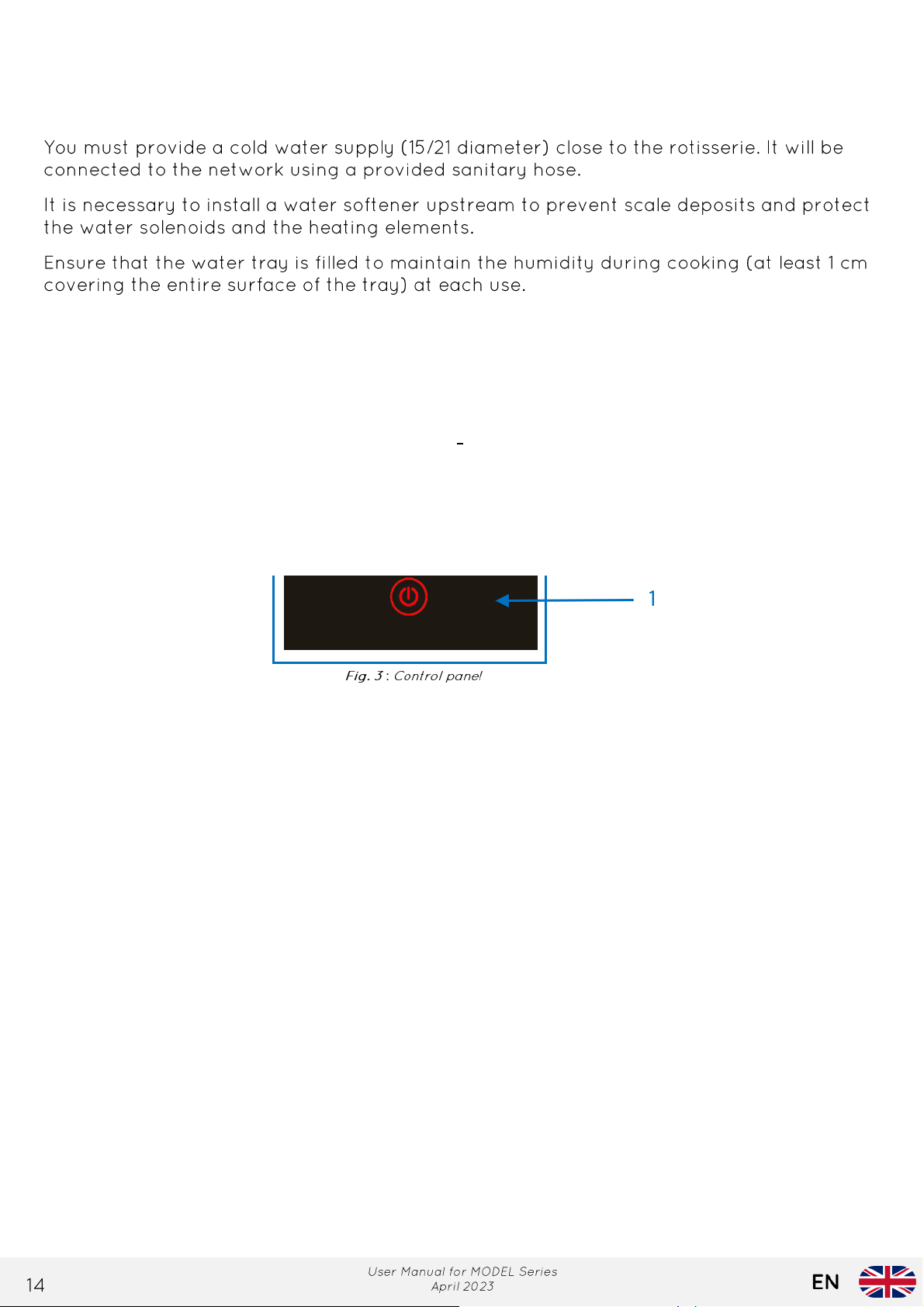
- A control panel 13
(Fig. 3)
.
Page 9
3.2 General components
Page 10
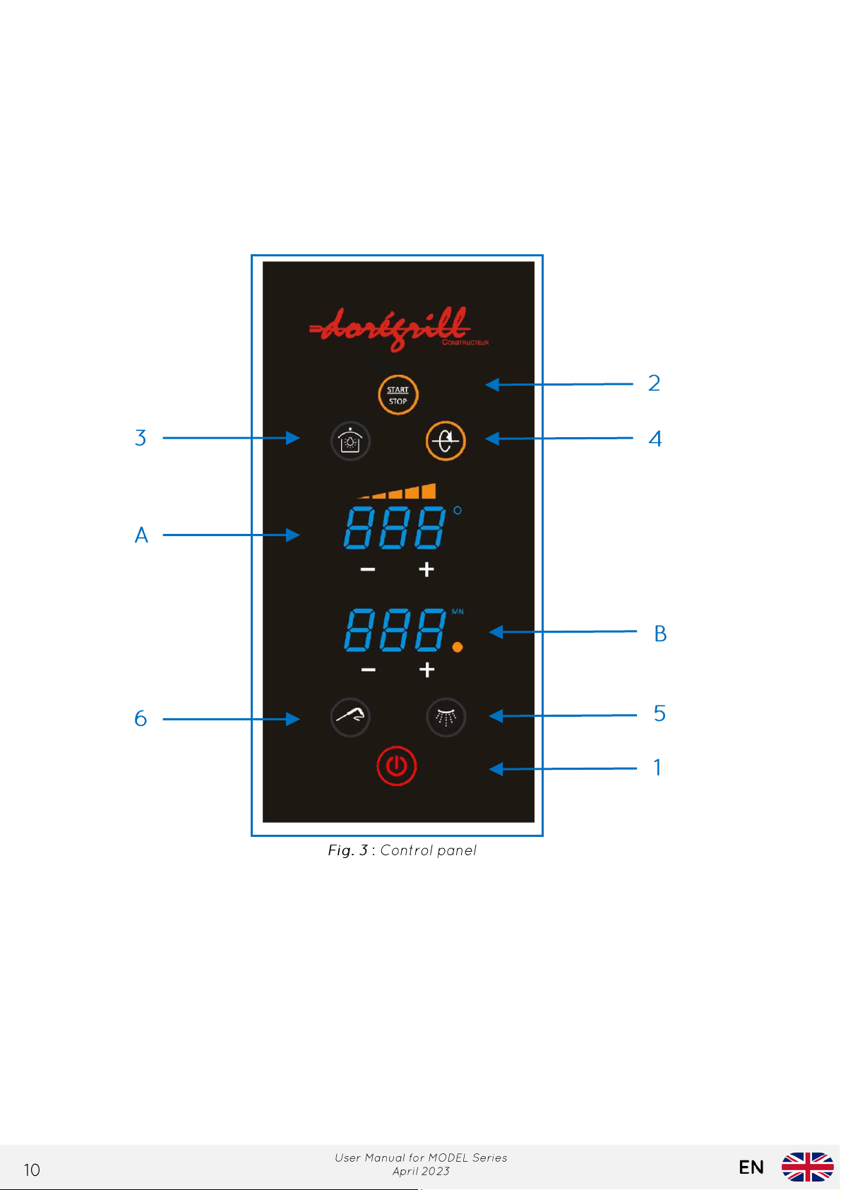
3.3 Control panel
1- Power light button
2- Cooking light button
3- Temperature maintenance light button (rotisserie in temperature maintenance mode
aftercooking)
4- Motor rotation light button
5- Cleaning cycle light button
6- Probe light button (optional)
A- Temperature display
B- Time display
Page 11
1- Power light touch button: touch and hold for a few seconds to activate or deactivate the
Number of LED
0 LED
1 LED
2 LED
3 LED
4 LED
5 LED
Approximate
temperature
Number of LED
0 LED
1 LED
2 LED
3 LED
4 LED
5 LED
Approximate
temperature
IMPORTANT: Cooking setting recommendation after factory test, 5 LEDs lit
IMPORTANT: The cleaning cycle must be started COLD (40°C max), meaning once the
rotisserie has cooled down.
touch screen controls.
2- Cooking light touch button: touch to start the cooking mode -> countdown is active.
3- Light and temperature maintenance touch button: touch to turn on/off.
4- Motor rotation control light touch button: touch to start/stop the motor.
5- Illuminated button to start the cleaning cycle. Duration 15 minutes
6- Option probe sensor, after pressing the illuminated button (core temperature of the poultry),
the display starts flashing, and the temperature measurement is in progress.
Temperature Display (A)
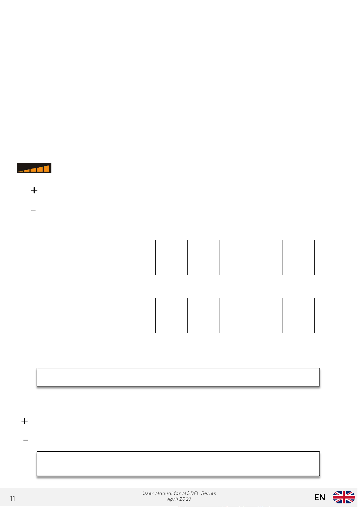
- Temperature level indicator LEDs. There are 5 of these LEDs, and they indicate the
selected heating level (either "cooking" or "temperature maintenance" mode).
- Temperature increase: Repeatedly pressing this button will increase the cooking
temperature (up to a maximum of 5 LEDs).
- Temperature decrease: Repeatedly pressing this button will decrease the cooking
temperature (down to a minimum of 1 LED).
Cooking mode
Temperature maintenance mode
- Temperature display :
Indicates the ambient temperature of the heating volume.
Timer display (B)
149°F 212°F 275°F 338°F 392°F 446 °F
149°F 167°F 176°F 185°F 194°F 203°F
- Increasing the cooking time: Successive presses of this button increase the cooking time
(up to 120 minutes)- Decreasing the cooking time: Successive presses of this button
decrease the cooking time.
Page 12

3.4 Rotisserie Dimensions
Refer to Chapter 8, ‘’Technical Specifications’’.
3.5 Technical Data
Refer to Chapter 8, ‘’Technical Specifications’’.
3.6 Intended use
Our rotisseries are intended for cooking meats and poultry prepared for use in the hot food and
catering sections of foodservice professionals.
3.7 Electrical diagram
Refer to Chapter 8, ‘’Technical Specifications’’.
Page 13
SETUP
IMPORTANT: Maintain a minimum air gap of 150 mm at the rear and sides of the
walls, as well as the tempered glass of the appliance.
IMPORTANT: Ensure that the electrical circuit protection is sufficient and complies
pow er devices protected by a suitable differential device.
4.1 General instructions
The installation of rotisseries as objects (positioning and connection) must be carried out by
authorized personnel with the technical and professional skills required to perform this
installation in compliance with the standards in force in the country of use of this equipment. See
Chapter 9, '’Installation’'.
4.2 Installation
Unpack the rotisserie, spits, and accessories. Place the rotisserie away from any combustible
materials (wood, plastics...). In case of proximity to such materials, they should be protected with
insulating materials.Unpack the rotisserie, spits, and accessories. Place the rotisserie away from
any combustible materials (wood, plastics...). In case of proximity to such materials, they should
be protected with insulating materials.
rotisserie to allow for proper ventilation and protection of adjacent equipment or
4.3 Electrical Connection
Check that the mains voltage matches the specifications indicated on the nameplate affixed at
the bottom left of the device.
The rotisserie must be connected to the power supply network through an outlet that is earthed.
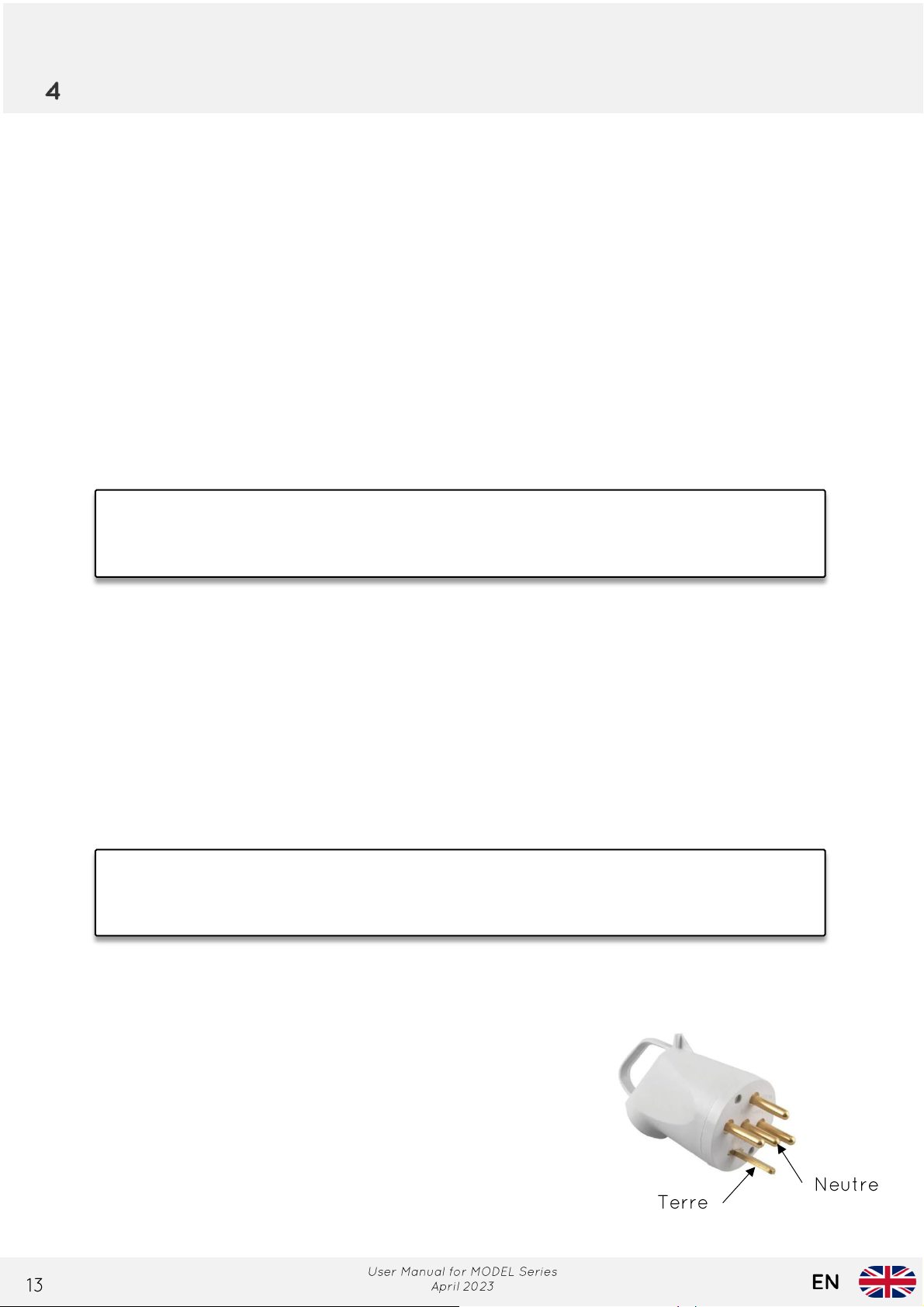
The connection must be 400V + N + T Three-phase. Ensure there is no connection error (such as
phase and neutral reversal, for example).
with the NF C 15-10 0 standard, which means having a dedicated circuit for high-
Refer to the electrical standards in force in the country where the device is used.
Preparation :
Operating voltage: 220V - 3 Phases + Neutral + Ground
In the case of an outdoor rotisserie, provide waterproof outlets.
Page 14
4.4 W ater connection
4.5 C ooking
- Place the poultry in the rotisserie after poking and seasoning them.
- Power on the touch screen control with button 1.
- Select the cooking temperature using the + and - buttons (usually, 5 LEDs lit for poultry
cooking).
- Set the cooking time using the + and - buttons.
- Press button 2 to start cooking; the countdown timer begins.
Page 15
MAINTENANCE
5.1 Disassembly for Cleaning
Inside the machine : accessories
Remove the spits and their support.
To remove the rotisserie's axis, ensure that the drive unit is in the vertical position.
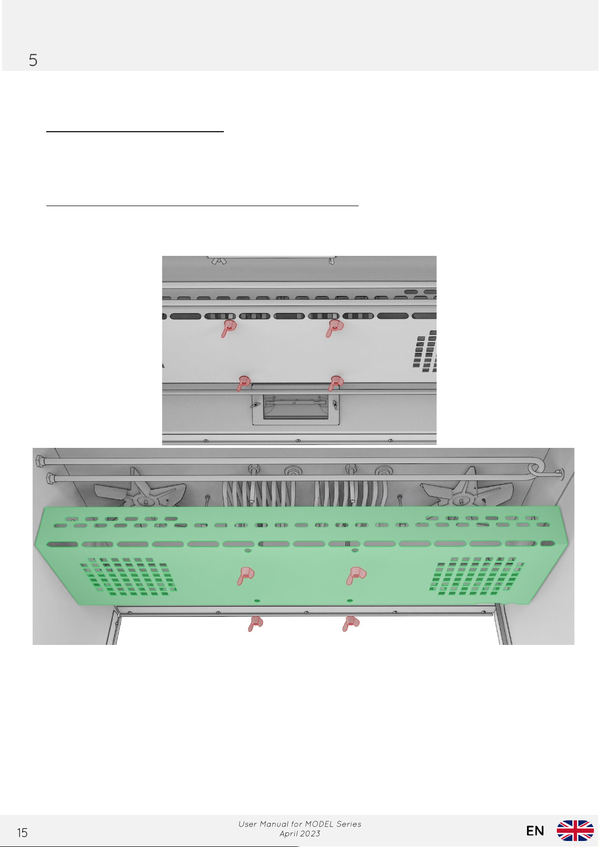
Inside the machine : ventilation cover fixed on the ceiling
This maintenance should be performed at least once a week, more frequently in the case of
frequent use.
- Start by unscrewing the 4 wing nuts.
- Remove the stainless steel protective cover to access the fan.
- Ensure this cover with ventilation holes is thoroughly cleaned.
- Disassemble the fan by unscrewing the reverse-threaded wing nut (clockwise).
- Perform the cleaning of the cover and fan through soaking and wash the ceiling.
- Reassemble everything by performing the reverse steps.
Page 16
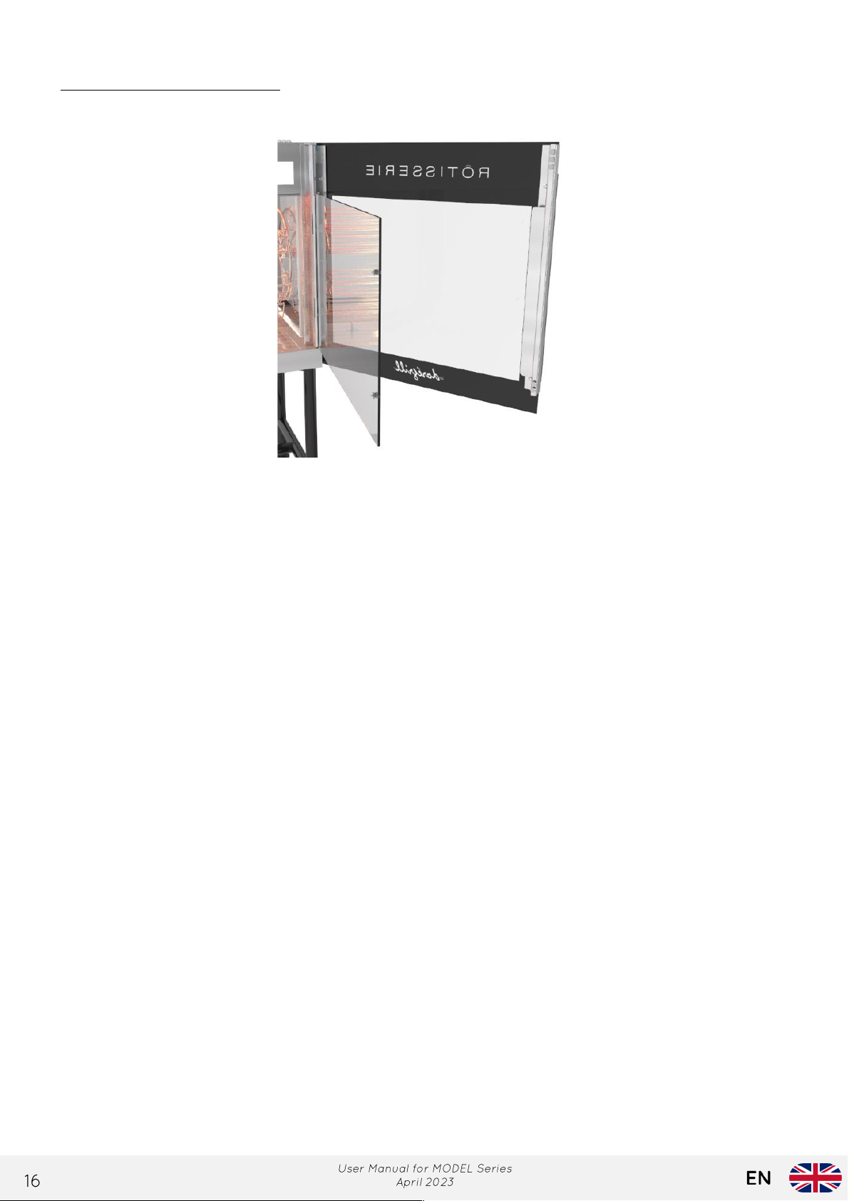
Cleaning the double glazing
The separate opening of the two panes allows cleaning of all glass surfaces.
5.2 Longevity of Armored Elements
All our armored resistances are of the "Incoloy" quality. They are located at the top of the
appliance, on either side of the air distribution housing.
Despite their quality, and given the power of the new cleaning products, these elements can be
altered and weakened. To prevent premature aging of your equipment, it is recommended to
protect these elements with aluminum foil when spraying your cleaning product.
Before restarting, thoroughly wipe the resistances with a wrung-out sponge to remove any traces
of cleaning product.
Page 17
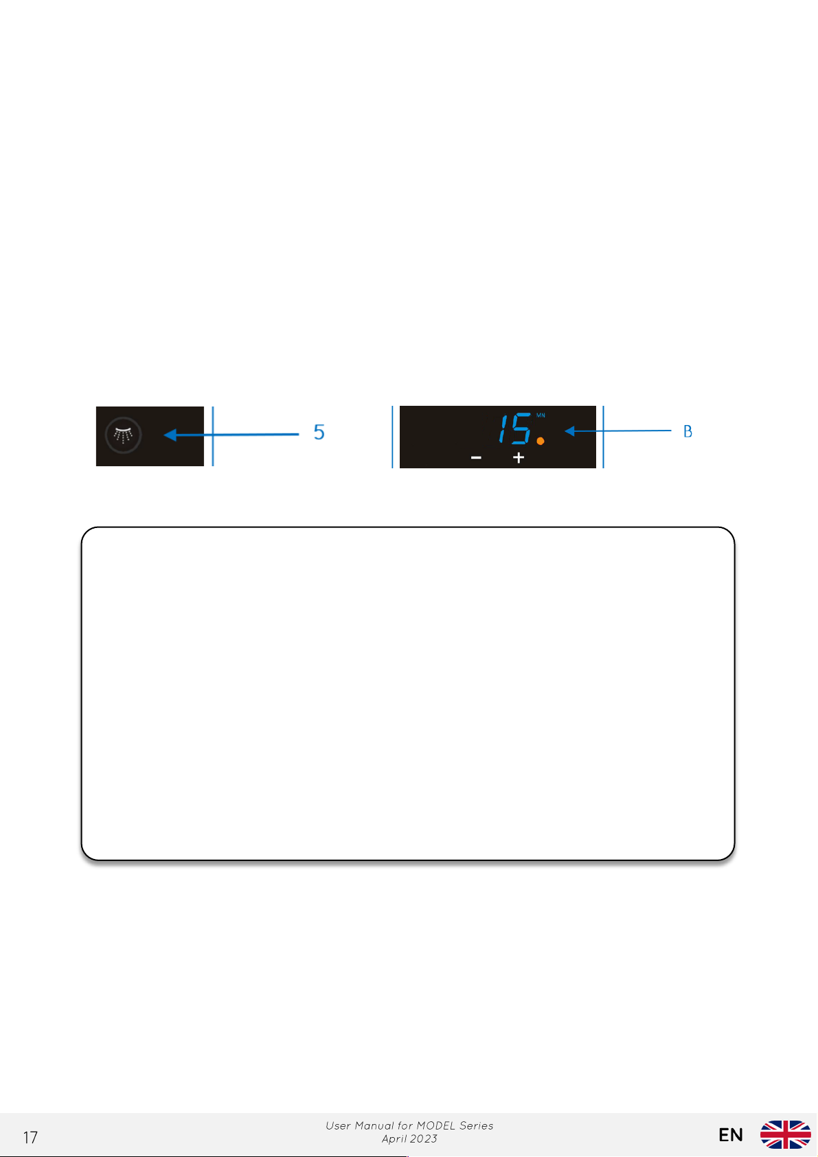
5.3 Automatic Cleaning Cycle
IMPORTANT :
six months.
This cycle assists in cleaning by generating steam for 15 minutes inside the cooking chamber.
Procedure :
- Connect the rotisserie to the water supply using the stainless steel sanitary hose provided
with the machine.
- Turn on the water tap.
- Remove all accessories that need to be washed (axle, spits, etc.)
- Turn off other programs and functions. Only indicator light 1 should be on.
- Start the cleaning cycle (button 5). The time display shows 15 minutes.
- At the end of the cycle, wipe down all surfaces with a sponge.
- Finally, empty the sauce tray using the drain plug, making sure to position a container
under the drain.
- In some cases, especially during intensive cooking, it may be necessary to run a
second cleaning cycle.
- Never use a high-pressure cleaner.
- Use only food-safe, "special oven" cleaning products.
- The use of bleach or any chlorine-based product w ill cause oxidation of the
stainless steel.
- Don't forget to w ipe the shielded heating elements clean before restarting if
cleaning products have splashed on them.
- Avoid using aluminum foil.
- Ensure that the juice tray is filled to half its height and maintain the level during
cooking.
REMINDER :
Current regulations require cleaning exhaust hoods and extraction systems every
Page 18

MAIN CAUSES OF TEMPERED GLASS BREAKAGE
IMPORTANT: Glass, whether tempered or not, is a fragile material that should be
one of the aforementioned causes being responsible for it.
6.1 Thermal Shock
The temperature difference between two specific points on the glass should not exceed 80°C.
When this limit is exceeded, it can cause a point of rupture, leading to the glass shattering
instantly. For instance, cleaning a hot glass surface with a cold sponge.
6.2 Blows to the glass
When an accidental impact occurs on tempered glass, specifically on the edge or corner of it, a
tiny piece of glass, sometimes as small as a pinhead, can break off. Once this happens, the
glass's molecular balance is disrupted, and glass breakage becomes inevitable, whether it occurs
within an hour or in the following days.
Such impacts can happen during equipment unpacking or when the user inadvertently strikes
one of the accessories (spit, basket, sauce dish, etc.) against the edge of the glass while installing
them.
6.3 Handling
Frequent and unnecessary movements, such as taking the rotisserie out onto the sidewalk every
day, prematurely weaken the glass surfaces.
handled with care. Sensitive to impacts, glass cannot break on its ow n, without
Page 19
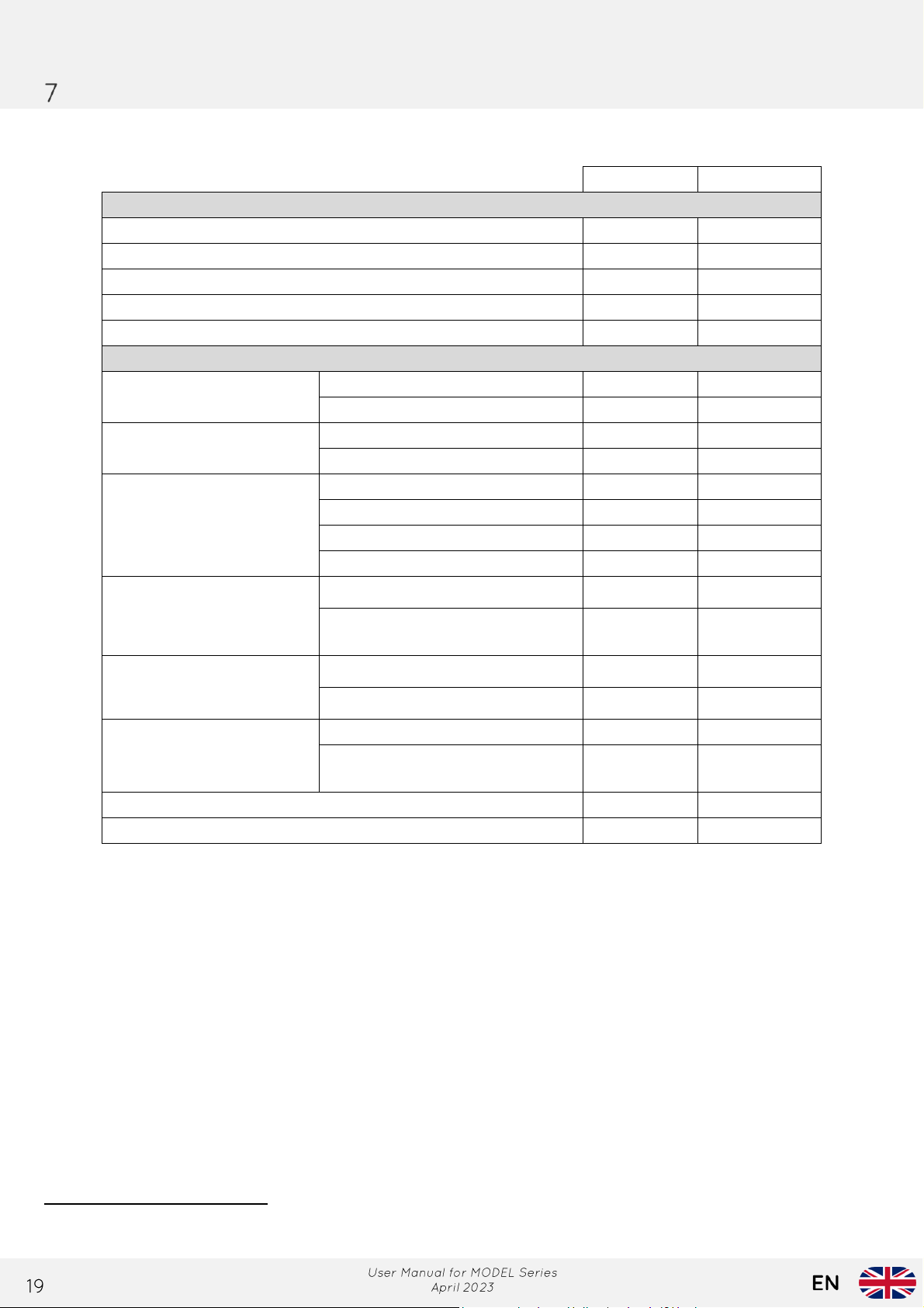
TECHNICAL SPECIFICATIONS
MODEL 6
MODEL 9
DIMENSIONS
Overall length
Overall depth
Height of the rotisserie on the stand/trolley
Total empty weight
Maximum load to be observed
COMPOSANTS TECHNIQUES
Baskets
Number
6
9
Length usable
Drive motor
Number
1
1
Power
35 W
35 W
Resistances
Pin shape
2
4
Unit power
3.3 KW
2.8 KW
Formed shape
2
2
Unit power
2 KW
2 KW
Ambient lamp
Number
2
2
Voltage / Amperage
230V /
300W
230V /
300W
Hot air fan
Number
2
2
Voltage / Power
73 W
73 W
Power cable
Section
5G2.5²
3G4²
Fiche : 3 Phases + Neutral +
Earth
Capacity in number of poultry (according to size)1
20/30
30/45
Total electrical consumption with lighting.
11 KW
16 KW
40 1/8" 40 1/8"
30 1/2" 37 1/2"
35 3/4" 43"
370 lbs 526 lbs
88 lbs 132 lbs
28 1/2" 28 1/2"
Yes Yes
1
These capacities are provided as an indication and depend on the size of the poultry.
Page 20
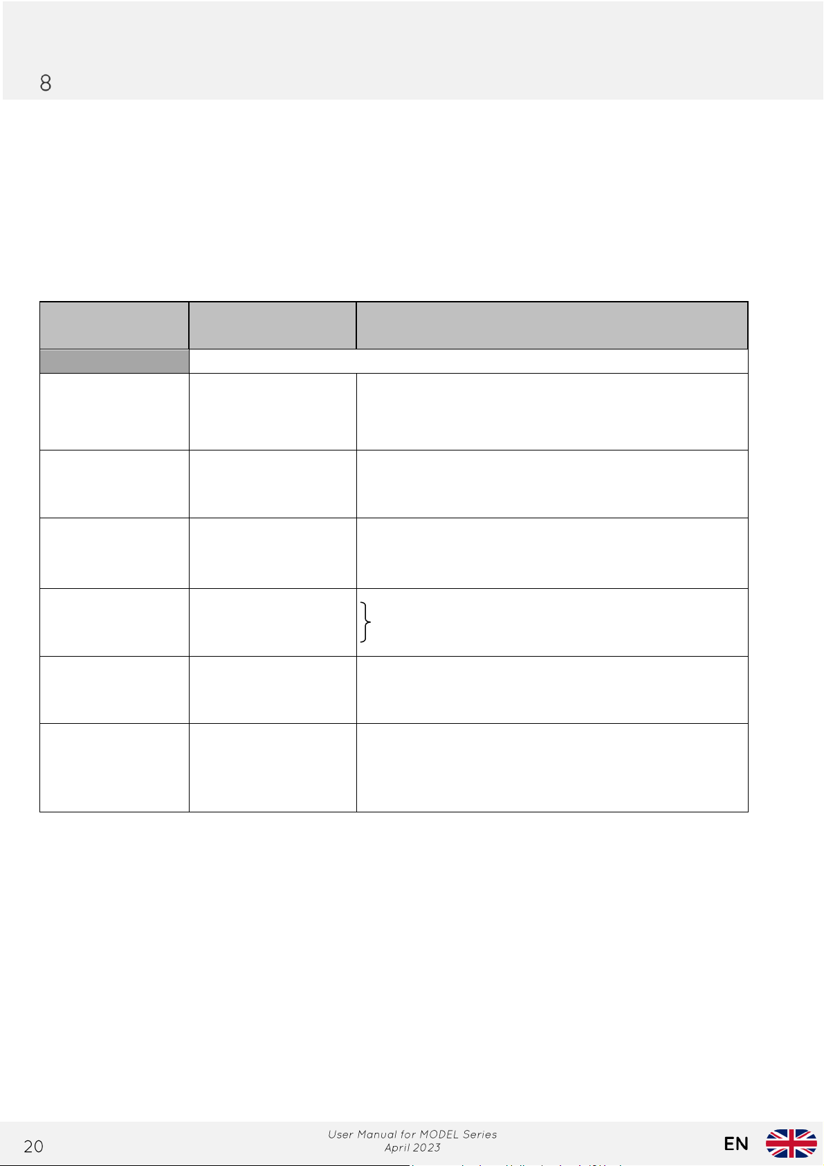
MAINTENANCE / AFTER-SALES SERVICE
DEFECTS
OBSERVED
POSSIBLE CAUSES
REMEDIES TO BE APPLIED
Electrical Circuit
The touchscreen
display is not
lighting up
-Non-existent power
supply
-lug the electrical plug into the socket. Reset the circuit
breaker and replace the device's protective fuse.
If the issue persists, contact your installer.
One ambient lamp
is turned off
-Defective bulb
-Faulty electrical
connection
-Change the light bulb
-Call the installer
All ambient lights
are off
-Faulty electrical
connection
-Faulty switch
-Call the installer
-Call the installer
The swings are not
turning
-Defective motor
-Faulty electrical
connection
Call the installer
Very long cooking
time
-Defective heating
elements
-Call the installer
The spits are not
rotating, and the
ambient lights are
off
-Emergency stop
switch is stuck
-Defective electrical
connection
-Pull on the emergency stop switch head.
-Call the installer
Any repairs on your device should be carried out by a qualified professional.
8.1 Fault finding
This section aims to list the main breakdowns that any user may encounter, provide their possible
causes, and offer solutions for addressing them without external intervention.
Page 21

8.2 Specific repairs
IMPORTANT: Before changing a still hot light bulb, wait a few minutes for it to
cool dow n to avoid the risk of burns.
8.2.1 Changing a Bulb
This operation can be performed by the user.
Disconnect the electrical power supply to the rotisserie.
Unscrew the wing nut (or butterfly nut) and the washer. Slide and remove the glass screen.
Remove the burnt-out light bulb and replace it with an identical model. When handling the bulb,
never touch it with bare fingers. Always use a clean piece of paper or cloth. Even the slightest
trace of fingerprints or grease can render the bulb unusable.
If the bulb appears dirty, clean it with alcohol and a soft cloth.
Reinstall the glass screen by sliding it into the clip. Then, thread the washer onto the screw and
moderately tighten the wing nut to avoid damaging the glass plate.
8.2.2 Opening of the technical housing
The technical housing is located on the left side of the rotisserie, behind the control panel. It
provides access for maintenance and repair of various electrical circuit components.
Page 22
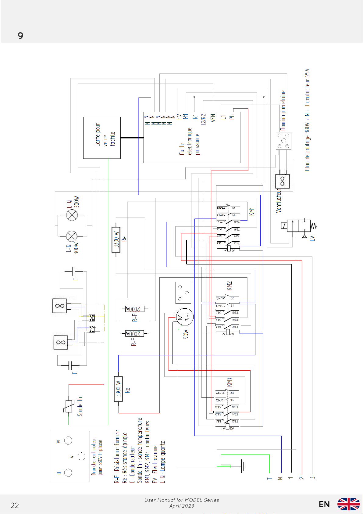
DIAG RAMS
9.1 Electrical Diagram for MODEL 6
Page 23
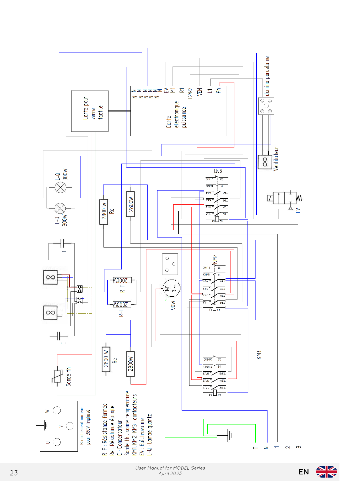
9.2 Electrical Diagram for MODEL 9
Page 24
Page 25
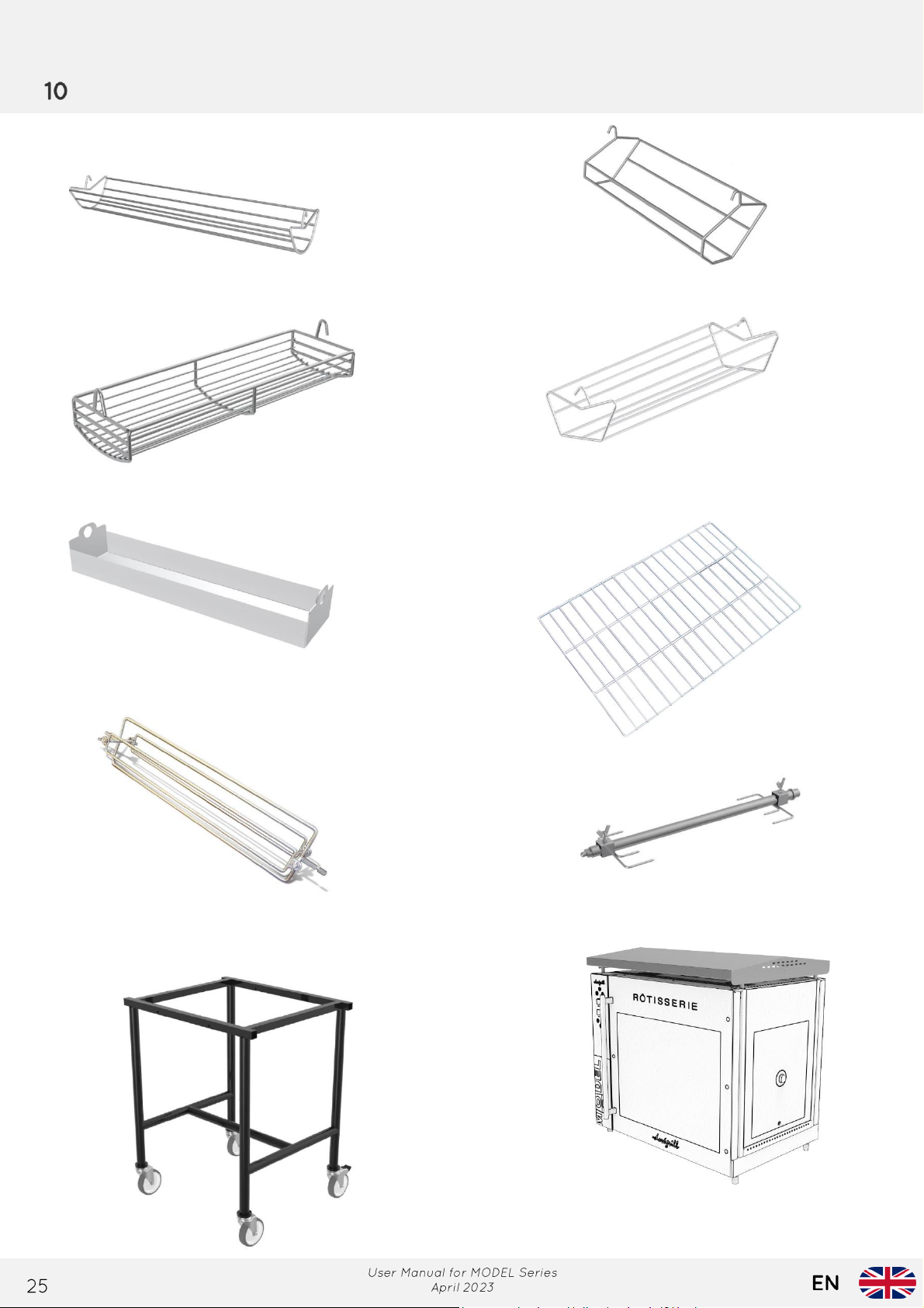
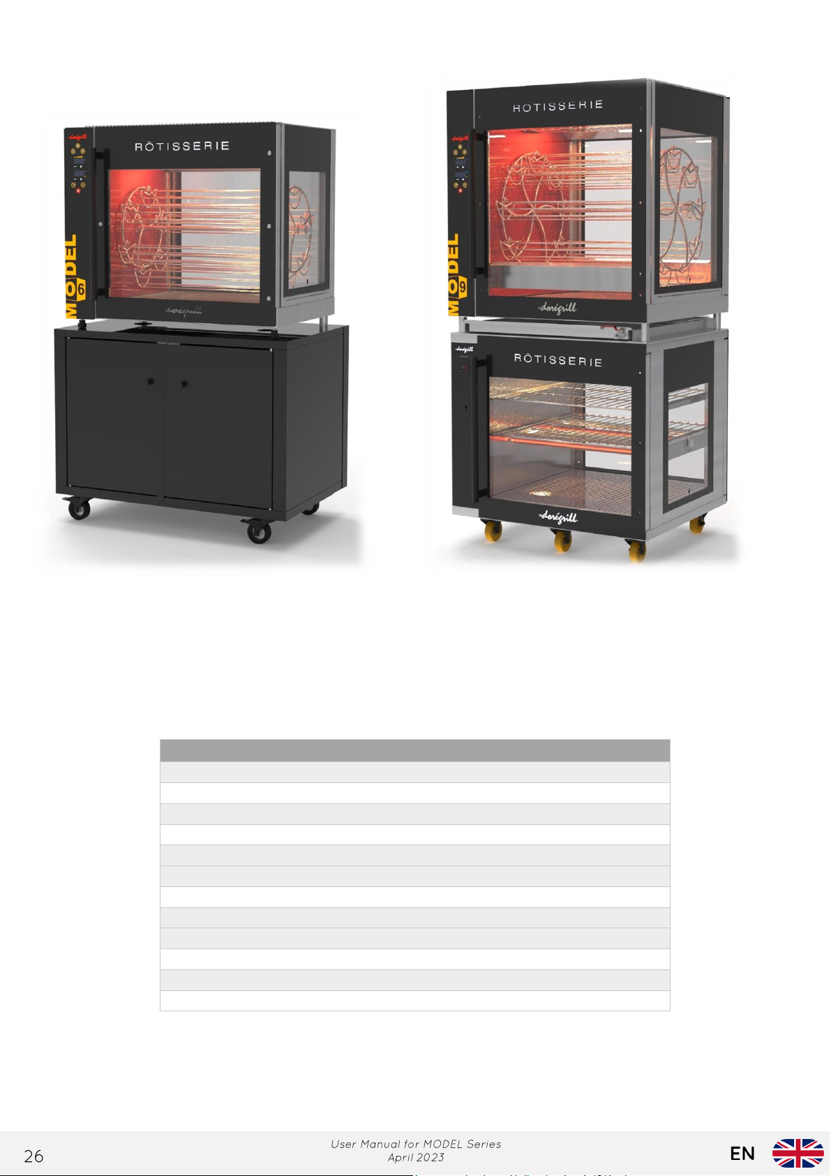
AC C ESSORIES
Standard baskets
Large piece baskets
Thighs baskets
Hollow tray
Grid
Large piece rotisserie
spit with forks
Large piece rotisserie
spit
Stand-up baskets
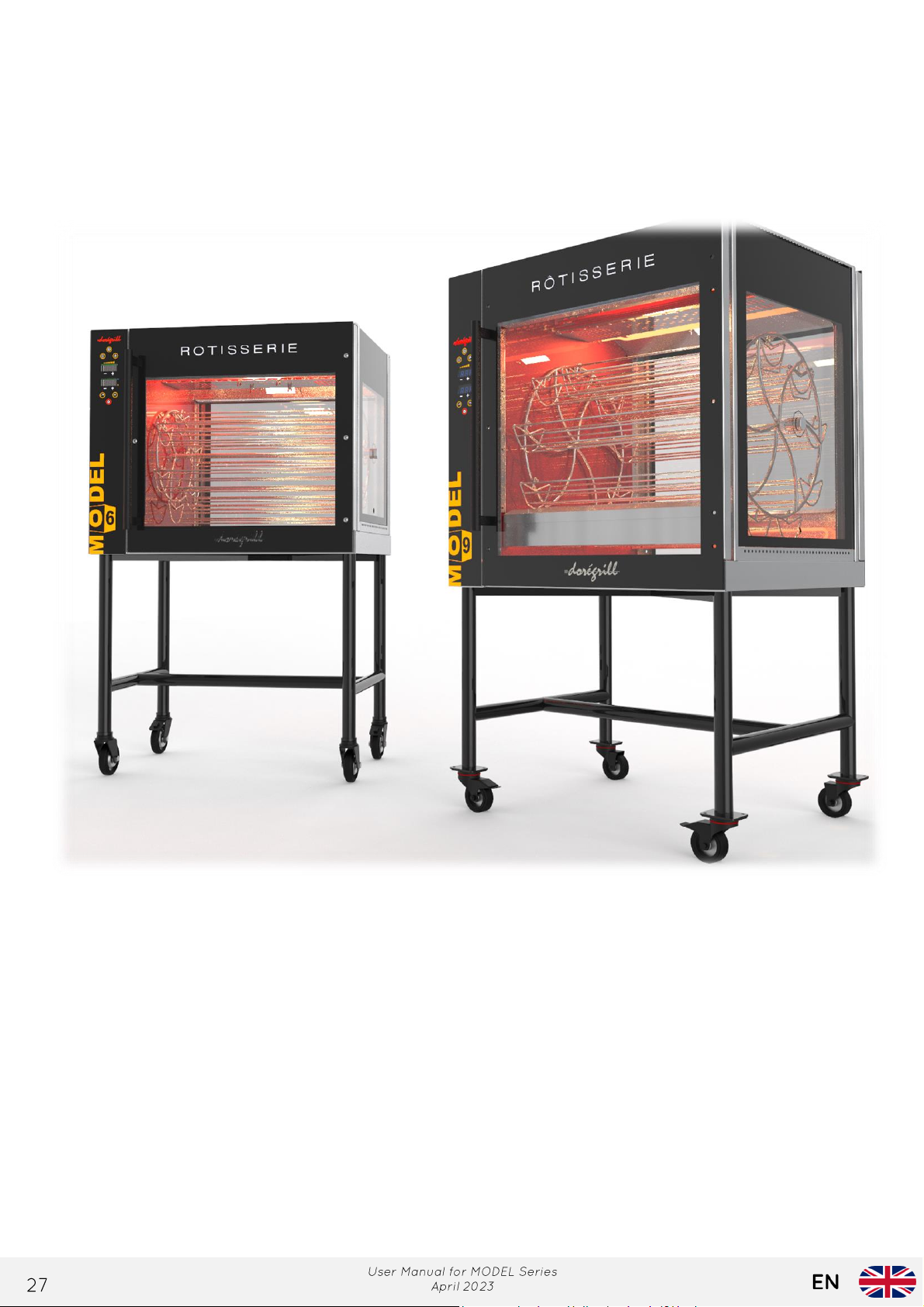
Rolling trolley
Roof
Page 26
Accessory references
Accessories
MODEL 6
MODEL 9
Standard baskets
AC00008
Stand-Up baskets
AC00006
Thighs baskets
AC00002
Large piece baskets
AC00004
Hollow tray
AC00088
Large piece rotisserie spit
AC00044
Large piece rotisserie spit with forks
AC00028
Grid
AC00057
AC00058
Rolling trolley
KIT0063
KIT0064
Roof
AC00097
AC00098
Warming cabinet
MA00146
MA00147
Storage cabinet
MA00156
MA00157
Warming cabinet
Storage cabinet
Page 27
Page 28

 Loading...