

Page 1

Dorchester DR-LP Range
of Hot Water Storage Heaters
Open Flue, Direct Gas Fired Hot Water Storage
Heaters with Permanent Pilot Ignition
for Domestic Hot Water Installations
Installation, Commissioning
and Servicing Instructions
DORCHESTER DR-LP 30, 40, 45, 60, 75, 95 Models
NOTE: THESE INSTRUCTIONS MUST BE READ AND UNDERSTOOD BEFORE
INSTALLING, COMMISSIONING, OPERATING OR SERVICING EQUIPMENT.
THIS WATER HEATER IS FOR USE ON GROUP H NATURAL GAS (2
RD
LPG (3
FAMILY) I3+. PLEASE ENSURE RELEVANT INFORMATION REQUIRED WITHIN
ND
FAMILY) I2H OR
DOCUMENT IS FOUND RELATING TO SPECIFIC GAS TO BE FIRED BEFORE FIRING
HEATER.
THIS WATER HEATER COMPLIES WITH ALL RELEVANT EUROPEAN DIRECTIVES.
PUBLICATION NO. 500001136 (0307 246)
ISSUE ‘A1
JUNE 2010
.1’
1
Page 2

2
Page 3

gis
gis
Table of contents
1 Introduction - - - - - - - - - - - - - - - - - - - - - - - - - - - 7
1.1 About the water heater - - - - - - - - - - - - - - - - - - - - - - - - - - - 7
1.2 What to do if you smell gas- - - - - - - - - - - - - - - - - - - - - - - - - 7
1.3 Regulations - - - - - - - - - - - - - - - - - - - - - - - - - - - - - - - - 7
1.4 Target groups - - - - - - - - - - - - - - - - - - - - - - - - - - - - - - - 8
1.5 Maintenance - - - - - - - - - - - - - - - - - - - - - - - - - - - - - - - - 9
1.6 Forms of notation - - - - - - - - - - - - - - - - - - - - - - - - - - - - - 9
1.7 Overview of this document - - - - - - - - - - - - - - - - - - - - - - - - 10
2 Functioning of the water heater - - - - - - - - - - - - - - - - 11
2.1 Introduction - - - - - - - - - - - - - - - - - - - - - - - - - - - - - - - 11
2.2 Functional description of the water heater - - - - - - - - - - - - - - - - 12
2.3 Heating cycle of the water heater - - - - - - - - - - - - - - - - - - - - - 13
2.4 Protection for the water heater - - - - - - - - - - - - - - - - - - - - - - 13
2.4.1 Gas control - - - - - - - - - - - - - - - - - - - - - - - - - - 13
2.4.2 Thermocouple- - - - - - - - - - - - - - - - - - - - - - - - - 13
2.4.3 Water temperature protection - - - - - - - - - - - - - - - - - 13
2.4.4 Combustion products discharge safety device - - - - - - - - - 14
2.5 Safety of the installation - - - - - - - - - - - - - - - - - - - - - - - - - 14
2.5.1 Unvented installation - - - - - - - - - - - - - - - - - - - - - 14
2.5.2 Vented installation- - - - - - - - - - - - - - - - - - - - - - - 14
2.5.3 Temparature and Pressure valve (T&P valve) - - - - - - - - - 14
2.6 Indicators and Alarms - - - - - - - - - - - - - - - - - - - - - - - - - - 15
2.6.1 Volt Free Contacts - - - - - - - - - - - - - - - - - - - - - - 15
2.7 Options - - - - - - - - - - - - - - - - - - - - - - - - - - - - - - - - - 15
2.7.1 LPG- - - - - - - - - - - - - - - - - - - - - - - - - - - - - - 15
2.7.2 Unvented Supply - - - - - - - - - - - - - - - - - - - - - - - 15
2.7.3 Top to Bottom Circulation - - - - - - - - - - - - - - - - - - - 15
3 Installation - - - - - - - - - - - - - - - - - - - - - - - - - - - 17
3.1 Introduction - - - - - - - - - - - - - - - - - - - - - - - - - - - - - - - 17
3.2 Packaging - - - - - - - - - - - - - - - - - - - - - - - - - - - - - - - - 19
3.3 Environmental conditions- - - - - - - - - - - - - - - - - - - - - - - - - 19
3.3.1 Working clearances - - - - - - - - - - - - - - - - - - - - - - 19
3.3.2 Humidity and ambient temperature- - - - - - - - - - - - - - - 19
3.3.3 Maximum floor loading - - - - - - - - - - - - - - - - - - - - 20
3.4 Technical specifications - - - - - - - - - - - - - - - - - - - - - - - - - 20
3.5 Installation diagrams - - - - - - - - - - - - - - - - - - - - - - - - - - - 22
3.6 Water connections Unvented - - - - - - - - - - - - - - - - - - - - - - - 22
3.6.1 Cold water side - - - - - - - - - - - - - - - - - - - - - - - - 22
3.6.2 Top to bottom recirculating pump - - - - - - - - - - - - - - - 22
3.6.3 Hot water side- - - - - - - - - - - - - - - - - - - - - - - - - 23
3.6.4 Drain valve - - - - - - - - - - - - - - - - - - - - - - - - - - 24
3.6.5 Circulation pipe - - - - - - - - - - - - - - - - - - - - - - - - 24
3.7 Water connections Vented - - - - - - - - - - - - - - - - - - - - - - - - 24
3.7.1 Cold water side - - - - - - - - - - - - - - - - - - - - - - - - 24
3.7.2 Top to bottom recirculating pump - - - - - - - - - - - - - - - 24
3.7.3 Hot water side- - - - - - - - - - - - - - - - - - - - - - - - - 24
3.7.4 Circulation pipe - - - - - - - - - - - - - - - - - - - - - - - - 25
Instruction manual DR-LP 3
Page 4

gis
3.8 Gas connection - - - - - - - - - - - - - - - - - - - - - - - - - - - - - - 25
3.9 Flue gas discharge - - - - - - - - - - - - - - - - - - - - - - - - - - - - 25
3.9.1 Introduction - - - - - - - - - - - - - - - - - - - - - - - - - - 25
3.9.2 Fitting the draught diverter - - - - - - - - - - - - - - - - - - - 26
3.9.3 Flue gas thermostat assembly - - - - - - - - - - - - - - - - - 27
3.10 Electrical connection - - - - - - - - - - - - - - - - - - - - - - - - - - - 27
3.10.1 Introduction - - - - - - - - - - - - - - - - - - - - - - - - - - 28
3.10.2 Mains power - - - - - - - - - - - - - - - - - - - - - - - - - - 29
3.11 Conversion to a different gas category - - - - - - - - - - - - - - - - - - - 29
3.11.1 Introduction - - - - - - - - - - - - - - - - - - - - - - - - - - 30
3.11.2 Conversion to a different gas category - - - - - - - - - - - - - 30
3.12 Checking the supply pressure and burner pressure - - - - - - - - - - - - 32
4 Filling and draining - - - - - - - - - - - - - - - - - - - - - - - 35
4.1 Introduction - - - - - - - - - - - - - - - - - - - - - - - - - - - - - - - - 35
4.2 Filling the water heater - - - - - - - - - - - - - - - - - - - - - - - - - - 36
4.2.1 Filling unvented installations - - - - - - - - - - - - - - - - - - 36
4.2.2 Filling vented installations- - - - - - - - - - - - - - - - - - - - 36
4.3 Draining the water heater - - - - - - - - - - - - - - - - - - - - - - - - - 36
4.3.1 Draining unvented installations - - - - - - - - - - - - - - - - - 36
4.3.2 Draining vented installations - - - - - - - - - - - - - - - - - - 37
5 Controls- - - - - - - - - - - - - - - - - - - - - - - - - - - - - 39
5.1 Introduction - - - - - - - - - - - - - - - - - - - - - - - - - - - - - - - - 39
5.2 Control panel - - - - - - - - - - - - - - - - - - - - - - - - - - - - - - - 39
5.3 Explanation of the symbols - - - - - - - - - - - - - - - - - - - - - - - - 40
5.4 On/Off-switch - - - - - - - - - - - - - - - - - - - - - - - - - - - - - - - 40
5.5 Control thermostat - - - - - - - - - - - - - - - - - - - - - - - - - - - - 40
5.6 Flue gas thermostat reset button - - - - - - - - - - - - - - - - - - - - - 40
6 Error states of the water heater- - - - - - - - - - - - - - - - - 43
6.1 Error states - - - - - - - - - - - - - - - - - - - - - - - - - - - - - - - - 43
7 Starting up and shutting down - - - - - - - - - - - - - - - - - 45
7.1 Introduction - - - - - - - - - - - - - - - - - - - - - - - - - - - - - - - - 45
7.2 Starting up - - - - - - - - - - - - - - - - - - - - - - - - - - - - - - - - 45
7.3 Shutting down- - - - - - - - - - - - - - - - - - - - - - - - - - - - - - - 46
7.3.1 Shut the water heater down for brief periods ("OFF mode") - - - 46
7.3.2 Isolate the water heater from the power supply - - - - - - - - - 46
7.3.3 Shut the water heater down for a longer period - - - - - - - - - 46
7.4 Heating cycle - - - - - - - - - - - - - - - - - - - - - - - - - - - - - - - 46
8 Troubleshooting - - - - - - - - - - - - - - - - - - - - - - - - 49
8.1 Introduction - - - - - - - - - - - - - - - - - - - - - - - - - - - - - - - - 49
8.2 Troubleshooting table for general errors - - - - - - - - - - - - - - - - - - 50
8.3 Troubleshooting table 'no hot water' - - - - - - - - - - - - - - - - - - - - 52
8.4 Troubleshooting table 'insufficient hot water' - - - - - - - - - - - - - - - - 53
9 Maintenance - - - - - - - - - - - - - - - - - - - - - - - - - - 55
9.1 Introduction - - - - - - - - - - - - - - - - - - - - - - - - - - - - - - - - 55
9.2 Preparing for maintenance - - - - - - - - - - - - - - - - - - - - - - - - 55
4 Instruction manual DR-LP
Page 5

gis
9.3 Water-side maintenance - - - - - - - - - - - - - - - - - - - - - - - - - 55
9.3.1 Introduction - - - - - - - - - - - - - - - - - - - - - - - - - - 55
9.3.2 Checking the anodes - - - - - - - - - - - - - - - - - - - - - 55
9.3.3 Descaling and cleaning the heater - - - - - - - - - - - - - - - 56
9.4 Gas-side maintenance - - - - - - - - - - - - - - - - - - - - - - - - - - 57
9.4.1 Introduction - - - - - - - - - - - - - - - - - - - - - - - - - - 57
9.4.2 Cleaning the burners - - - - - - - - - - - - - - - - - - - - - 57
9.4.3 Cleaning the injectors - - - - - - - - - - - - - - - - - - - - - 57
9.4.4 Checking the flue baffles - - - - - - - - - - - - - - - - - - - 57
9.5 Finalising maintenance- - - - - - - - - - - - - - - - - - - - - - - - - - 57
A DR-LP electrical diagram - - - - - - - - - - - - - - - - - - - - 59
Instruction manual DR-LP 5
Page 6

gis
6 Instruction manual DR-LP
Page 7
gis
gis
1 Introduction
About the water heater
1.1 About the water
heater
0063
1.2 What to do if you
smell gas
This manual describes how to install, service and use an DR-LP-water heater.
An DR-LP water heater is a gas-fired open water heater without a fan. The DRLP-water heater is fitted with a combustion products discharge safety device
and falls into the water heater category B
water heater's identification plate. The information in this manual is applicable
to types DR-LP: 30, 40, 45, 60, 75, 95.
The construction and fittings of each water heater conform to the European
standard for gas-fired storage water heaters for sanitary use (EN 89). The water
heaters are compliant with the European Directive on Gas Appliances and
thereby authorised to bear the CE mark.
Warning
Read this manual carefully before commissioning the water heater. Failure
to read the manual and to follow the printed instructions may lead to
personal injury and damage to the water heater.
Warning
Whenever there is a smell of gas:
No naked flames! No smoking!
Avoid causing sparks! Do not use any electrical equipment or switch, i.e. no
telephones, plugs or bells!
. This information is located on the
11B S
Shut off the mains gas supply!
Open windows and doors!
Warn occupants and leave the building!
After leaving the building, alert the gas distribution company or installer.
1.3 Regulations Gas Safety Installations and Use Regulations 1998, (As amended). It is law
that all gas appliances are installed by competent persons, in accordance with
the above regulations. Failure to install appliances correctly could lead to
prosecution. It is in your own interest, and that of safety, to ensure that this law
is complied with.
The installation of the boiler MUST be in accordance with the relevant
requirements of the Gas Safety Regulations, Building Regulations, IEE
Regulations and the Water Supply (water fittings) Regulations.
The installation should also be in accordance with any relevant requirements of
the HSE, local gas region and local authority and the relevant recommendations
of the following documents:
British Standards
• BS 6891: Specification for installation of low pressure gas pipework of up to
28 mm (R1) in domestic premises (2nd family gas). For larger installations
see IGE/UP/2 below.
Instruction manual DR-LP 7
Page 8
1
Introduction
gis
• BS 6798: Specification for installation of gas-fired boilers of rated input not
exceeding 70 kW net.
• BS 6644: Specification for installation of gas-fired hot water boilers of rated
inputs between 60 kW and 2 MW (2nd and 3rd family gases).
• BS 6700: Specification for design, installation, testing and maintenance of
services supplying water for domestic use within buildings and their
curtilages.
• BS EN 806-2: Specification for installations inside buildings conveying water
for human consumption. Part 2: Design.
• BS 5546: Specification for installation of hot water supplies for domestic
purposes, using gas-fired appliances of rated input not exceeding 70 kW.
• BS 5440: Installation and maintenance of flues and ventilation for gas
appliances of rated input not exceeding 70 kW net (1st, 2nd and 3rd family
gases). Part 1: Flues. Part 2: Ventilation.
Institute of Gas Engineers and Managers Publications
• IGE/UP/1 Soundness testing and purging of industrial and commercial gas
installations.
• IGE/UP/1A Soundness testing and direct purging of small low pressure
industrial and commercial natural gas installations.
• IGE/UP/2 Gas installation pipework, boosters and compressors on industrial
and commercial premises.
• IGE/UP/10 Installation of gas appliances in industrial and commercial
premises. Part 1: flued appliances.
CIBSE Publications:- "CIBSE Guide"
Section B4 : Water Service Systems.
1.4 Target groups The three target groups for this manual are:
• (end) users;
•installers;
• service engineers.
Symbols on each page indicate the target groups for whom the information is
intended. See Table 1.1.
Table 1. 1 Symbols for each target group
Symbol Target groups
(End) user
g
Installer
i
Service and maintenance engineer
s
8 Instruction manual DR-LP
Page 9
Maintenance
gis
1.5 Maintenance A service should be carried out at least once a year, both on the water side and
on the gas side. Maintenance frequency depends, among other things, on the
water quality, the average burning time per day and the set water temperature.
n Note
To determine the correct maintenance frequency, it is recommended to
arrange for the service engineer to check the water heater on both the water
and gas side, three months after installation. Based on this check, the best
maintenance frequency can be determined.
n Note
Regular maintenance extends the service life of the water heater.
Both the end user and the service engineer are responsible for regular
maintenance. They will need to establish clear agreements on this.
n Note
If the water heater is not regularly maintained, the warranty will become void.
1.6 Forms of notation The following notation is used in this manual:
n Note
Important information.
cCaution
Ignoring this information can lead to the water heater being damaged.
Warning
Failure to carefully read this information may lead to danger of personal
injury and serious damage to the water heater.
Instruction manual DR-LP 9
Page 10
1
Introduction
gis
1.7 Overview of this
document
Tab le 1.2 Content of document
Chapter Target groups Description
2 Functioning of the water
heater
3Installation
4 Filling and draining
Table 1.2 provides an overview of the contents of this document.
This chapter describes how the water heater functions.
gis
This chapter describes the installation activity to be completed
is
before you actually start up the water heater. Instructions are
also provided for the installation and/or service engineer on
converting the water heater to other types of gas.
This chapter describes how to fill and drain the water heater.
gis
5 Controls
6 Error states of the water
heater
7 Starting up and shutting
down
8 Troubleshooting
gis
gis
gis
gis
This chapter describes the water heater’s control panel and
how to use it.
This chapter describes each status (state) that the water
heater may be in and how to respond, if necessary.
This chapter describes how to start up the water heater and
how to shut it down for a brief or long period of time. The
general heating cycle of the water heater is also described.
This chapter is mainly intended for the installer and the service
engineer. It describes water heater errors. These errors are
indicated on the display. A table of possible causes and
solutions is provided. End users may also refer to this
additional information about the water heater.
9 Maintenance
s
This chapter sets out the maintenance tasks to be carried out
during a service.
10 Instruction manual DR-LP
Page 11

gis
gis
2 Functioning of the
water heater
2.1 Introduction This chapter successively covers the following topics:
• Functional description of the water heater
• Heating cycle of the water heater
• Protection for the water heater
• Safety of the installation
• Indicators and Alarms
• Options
Introduction
Instruction manual DR-LP 11
Page 12
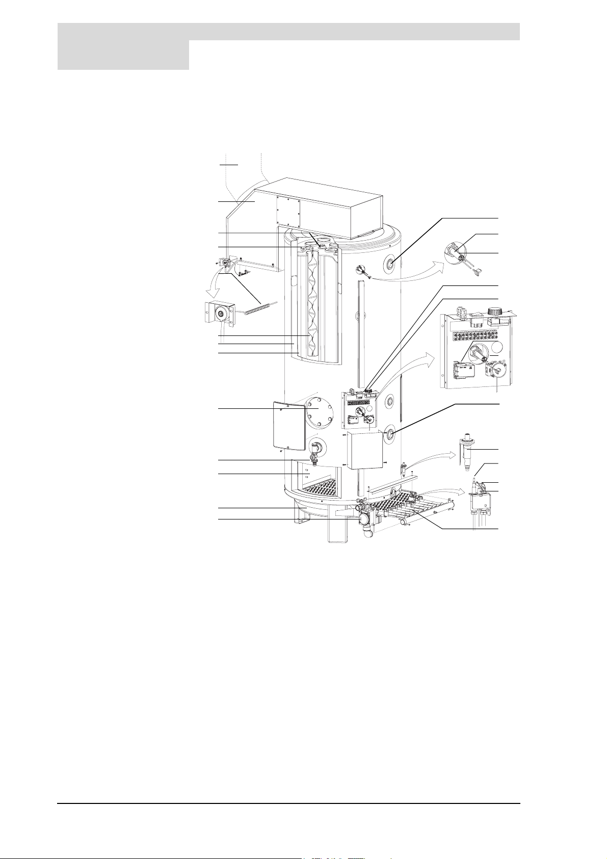
2
Functioning of the water heater
gis
2.2 Functional
description of the
water heater
Legend
a flue gas discharge
b draught diverter
c anodes
d flue tubes
e flue gas thermostat sensor
f flue gas thermostat
g flue baffles
h insulation layer
i hot water tank
j cleaning opening
k drain valve
l combustion chamber
m radiation shield/condensation
tray
n gas control
o hot water outlet
p safety thermostat sensor
q high-limit thermostat sensor
r control panel
s control thermostat
t high-limit thermostat
u control thermostat sensor
v safety thermostat
w cold water inlet
x piezo igniter
y thermo-couple
z pilot burner
A igniter electrode
B bar burners/burner tray
Figure 2.1 shows a cut-away view of the water heater.
a
b
c
d
e
f
g
h
i
j
k
l
m
n
o
p
q
r
s
t
u
v
w
x
y
z
A
B
IMD-0364
Figure 2.1 Cut-away view of the water heater
In this water heater the cold water enters the bottom of the it via the cold water
inlet w. The heat of combustion is transferred to the water through the
combustion chamber l and flue tubes d. The heated tap water leaves the
heater through the hot water outlet o. Once the water heater is completely filled
with water, it remains constantly under water supply pressure. As hot water from
the water heater is consumed, it is continuously replenished with cold water.
The water heater is fitted with a igniter electrode A which ignites the pilot
burner z. The gas that fuels the combustion flows via the gas control n into the
manifold, in which Injectors are located. Via these injectors, the gas enters the
bar burners B. Together the bar burners constitute the burner tray. As the gas
is injected into the bar burners, the primary air required for combustion is also
drawn in
When the gas/air mixture starts to flow, it is ignited by the pilot burner.
(1)
. Additional air is drawn through the openings in the burner tray.
12 Instruction manual DR-LP
Page 13

gis
Heating cycle of the water heater
The flue gases arising from combustion here are drawn upwards through the
flue tubes d. Flue baffles g are located in the flue tubes. These slow down the
flue gas exhaust, improving the heat transfer efficiency. The flue gases leave
the water heater via the draught diverter b. A radiation shield/condensation
tray m is fitted under the burner tray. This prevents overheating of the floor
surface under the water heater and serves as a collection tray for condensate.
The insulation layer h prevents heat loss. The inside of the hot water tank is
enamelled to protect against corrosion. The anodes c provide additional
protection.
2.3 Heating cycle of the
water heater
2.4 Protection for the
water heater
2.4.1 Gas control
The water heater is regulated by a control thermostat. The control thermostat
monitors the water temperature (T
activated as soon as T
value for T
As soon as T
thermostat closes, causing the main valve on the gas control to open. The gas
mixes with the air it draws along. This mixture is ignited by the pilot burner and
the water becomes heated. As soon as T
ceases, the thermostat opens again and the heating cycle stops.
The control thermostat has a certain margin both when closing and opening,
referred to as the hysteresis. The hysteresis cannot be adjusted.
The water heater is protected by means of the following:
• the Gas Control
• the Thermocouple
• the Water Temperature Safeguard
• the Combustion products discgarge safety device
The gas control has 2 valves for safety purposes:
1. The main valve, which controls the gas supply to the burner tray and which
is switched via the On/Off-switch circuit and the control, high-limit and flue
gas thermostats. This circuit is powered by the supply voltage.
2. The safety valve, which controls the gas supply to the pilot burner and which
is switched via the thermocouple circuit and the safety thermostat. This
circuit is powered by the millivolt potential from the thermocouple that is
located in the pilot flame. Whenever the safety valve closes, the main valve
also closes.
can be adjusted using the control thermostat (40°C ... 70°C).
set
drops below T
water
falls below the specified threshold value (T
water
). The water heater's heating cycle is
water
set
there is a demand for heat and the control
set
exceeds T
water
, the heat demand
set
). The
2.4.2 Thermocouple
1. To prevent gas flowing when there is no combustion, a thermocouple is
fitted. As a result of the presence of the (permanent) pilot flame, the thermocouple maintains a millivoltage potential which keeps the gas control's
safety valve open.
2. If the pilot flame goes out, this voltage disappears and the gas control's
safety valve closes, interrupting the gas supply to the burner tray.
2.4.3 Water temperature protection
To ensure a safe water temperature is not exceeded, the high-limit thermostat
sensor is installed at the top of the water heater. In the event of stratification of
the water temperature, the temperature at the top of the water heater can be
considerably higher than the set temperature for the hot water.
In the event that both the control and maximum thermostats should fail, there is
also a safety thermostat.
1. The gas flow is accelerated through the narrow opening in the injector. This creates a vacuum,
which also draws in air, through the Venturi effect.
Instruction manual DR-LP 13
Page 14
2
Functioning of the water heater
gis
Table 2.1 explains how the high-limit and safety thermostats respond to the
sensors.
Tab le 2.1 Temperature protection
Protection Description
High-limit thermostat If the high-limit thermostat sensor q detects a temperature greater
than 84°C, the high-limit thermostat opens and the gas control's main valve
circuit is broken, closing the valve. The heating cycle stops until the high-limit
thermostat closes again. At this point the gas control opens again and the
heating cycle is repeated. The high-limit protection also prevents excessive
scale forming in the water heater.
Safety thermostat If the safety thermostat sensor p detects a temperature greater than 93°C, the
safety thermostat opens. The gas control's safety valve circuit is broken and
the safety and main valve both close. Combustion immediately ceases and the
pilot flame also goes out.
In order to re-start the water heater, the pilot flame must be re-lit.
2.4.4 Combustion products discharge safety device
The flue gases are drawn outside via the draught diverter b and the flue gas
discharge a. To prevent the flue gases from flowing back into the installation
room, the discharge ducting is monitored by a feature called the combustion
products discharge safety device. For this purpose a flue gas thermostat
sensor e complete with flue gas thermostat f is fitted in the draught diverter.
Under normal circumstances this sensor measures the ambient temperature.
However, if the chimney is not drawing sufficiently (for example, due to a
blockage in the chimney), the flue gases will 'reflux' and flow back past the flue
gas thermostat sensor. The sensor then detects an excessive temperature and
the flue gas thermostat will open. The circuit of the main valve of the gas control
is interrupted and the valve closes, which forces the heating cycle to stop. The
flue gas discharge thermostat will be locked out and the water heater will require
a manual reset before it can be re-started.
2.5 Safety of the installation
2.5.1 Unvented installation
2.5.2 Vented installation
2.5.3 Temparature and Pressure valve (T&P valve)
With an unvented installation, an expension valve and expansion vessel prevent
excessive pressure in the water heather. This prevents damage of the water
heater. A non-return valve prevents excessive pressure in the water supply
system. This valve also prevents water from flowing backwards from the heater
into the cold water supply system. The pressure reducing regulates the water
supply pressure to a normal operating pressure of 3.5 bar. The components are
fitted to the cold water pipe. See paragraph 3.6.1 Cold water side.
With a vented installation, excess pressure is taken up by the open water tank.
The level of the water determines the working pressure which may not exceed
8 bar.The installation must also be fitted with an open vent from the hot water
pipe. Ideally the vent pipe should be linked to a separate tundish/drain or else
to the cold water storage tank. A safety valve should also be fitted to the water
heather. See paragraph 3.6.3 Hot water side.
A T&P valve is mandatory in an 'unvented' installation.
14 Instruction manual DR-LP
Page 15

Indicators and Alarms
gis
A T&P valve monitors the water pressure in the water heater and the water
temperature at the top of it. If the pressure in the water heater becomes
excessive (> 7 bar) or the water temperature is too high (>97°C), the valve will
open. The hot water will immediately flow out of the heater. Because the water
heater is under water supply pressure, cold water will automatically flow into it.
The valve remains open until the unsafe situation has been averted. A
connecting point for a T&P valve is standard on the water heater. See paragraph
3.6.3 Hot water side
2.6 Indicators and
Alarms
2.6.1 Volt Free Contacts
Volt free contacts are supplied as standard to give remote indication/alarm of
'normal run' and 'lockout'. The 'lockout' indication includes shut down due to
operation of the safety thermostat, loss of flame and failure to ignite.
2.7 Options The heaters can be supplied with the following additional variations, either
ready fitted or for site fitting:
2.7.1 LPG
The heaters can be supplied adjusted for use on propane or butane, see section
3.12. It is most important that the heater is correctly adjusted for the gas to be
fired.
2.7.2 Unvented Supply
The heaters can be supplied with a purpose designed and sized unvented kit
comprising pressure reducing valve, non-return valve, expansion vessel,
expansion relief valve and pressure/temperature relief valve, to enable the
heater to be coupled directly to the mains water. For details see 2.5.1, 2.5.3 and
3.6.
2.7.3 Top to Bottom Circulation
In order to give enhanced temperature control to aid compliance with the HSE
guidance and the DHss Code of Practice for 'The Control of Legionellae in
Health Care Premises', a pump circulation kit can be supplied comprising 230
volt single phase pump, non-return valve, pipe work and sufficient fittings to
contact between the hot water flow and the bottom connection. For details see
section 3.5 of this manual.
Instruction manual DR-LP 15
Page 16

2
Functioning of the water heater
gis
16 Instruction manual DR-LP
Page 17

Introduction
is
is
3 Installation
Warning
The installation should be carried out by an authorised installation engineer
in compliance with the official local regulations imposed by the gas, water
and power supply companies and the fire service.
The water heater may only be installed in a room which complies with the
requirements stated in national and local ventilation regulations.
See also paragraph 1.3 Regulations.
3.1 Introduction This chapter describes the installation activities to be carried out before the
water heater may be started up, namely:
• Packaging;
• Environmental conditions;
• Technical specifications;
• Water connections Unvented;
• Water connections Vented;
• Gas connection;
• Flue gas discharge;
• Electrical connection;
• Conversion to a different gas category;
• Checking the supply pressure and burner pressure;
n Note
Starting up the water heater is described in chapter 7 Starting up and
shutting down.
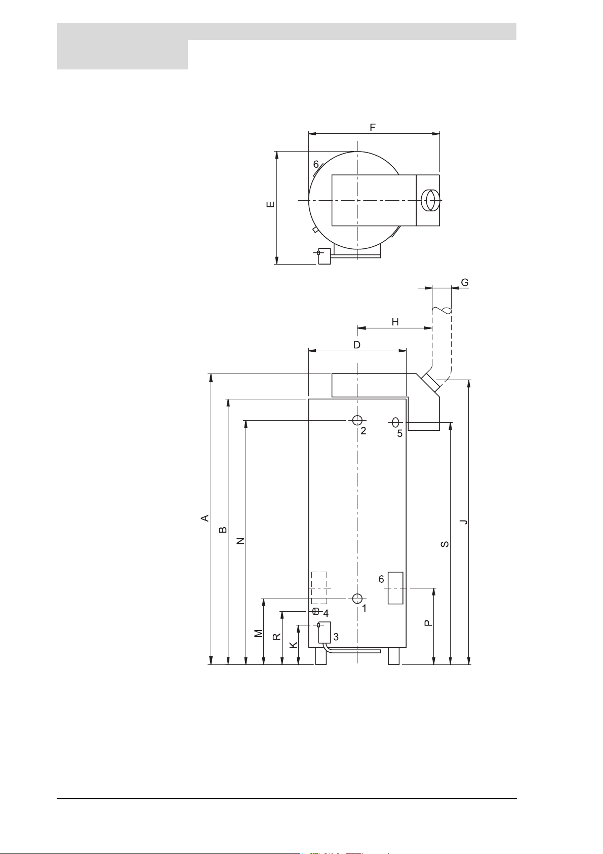
Figure 3.1 shows a plan and elevation drawing of the water heater.
Instruction manual DR-LP 17
Page 18
3
Installation
is
IMD-0365
Figure 3.1 Plan and elevation of the water heater
18 Instruction manual DR-LP
Page 19

Packaging
is
3.2 Packaging To avoid damaging the water heater, remove the packaging carefully.
We recommend unpacking the water heater at or near its intended location.
cCaution
The water heater may only be manoeuvered in an upright position. Take
care that the water heater is not damaged after unpacking.
cCaution
3.3 Environmental
conditions
3.3.1 Working clearances
The water heater may not be used in rooms where chemical substances are
stored or used due to the risk of explosion and corrosion to the water heater.
Some propellants, bleaching agents, degreasing agents etc. disperse
vapours which are explosive and/or which cause accelerated corrosion. If
the water heater is used in a room in which such substances are present,
the warranty will be void.
DR-LP-water heaters are open water heaters and may only be placed in an
open boiler room. They fall under category B
For access to the water heater it is recommended that the following
clearances are observed (see Figure 3.1):
• AA: around the water heater's control column and cleaning openings:
100 cm.
• BB: around the water heater itself: 50 cm.
• Above the water heater (room to replace the anodes):
- 100 cm if using fixed anodes or
- 50 cm if using flexible anodes.
If the available clearance is less than 100 cm, flexible magnesium anodes
may be ordered from Hamworthy heating limited.
11B S
.
n Note
When installing the water heater, be aware that any leakage from it and/or
connections can cause damage to the immediate environment or floors
below the level of the boiler room. If this is the case the water heater should
be installed above a wastewater drain or in a suitable metal leak tray.
The leak tray must have an appropriate wastewater drain and must be at
least 5 cm deep with a length and width at least 5 cm greater than the
diameter of the water heater.
3.3.2 Humidity and ambient temperature
The boiler room must be frost-free or be protected against frost. Table 3.1
shows the environmental specifications which must be observed to guarantee
correct functioning of the water heater.
Tab le 3.1 Humidity and ambient temperature specifications
Humidity and ambient temperature
Humidity max. 93% RH at +25°C
Ambient temperature Functional: 0 ≤ t ≤ 60°C
Instruction manual DR-LP 19
Page 20
3
Installation
is
3.3.3 Maximum floor loading
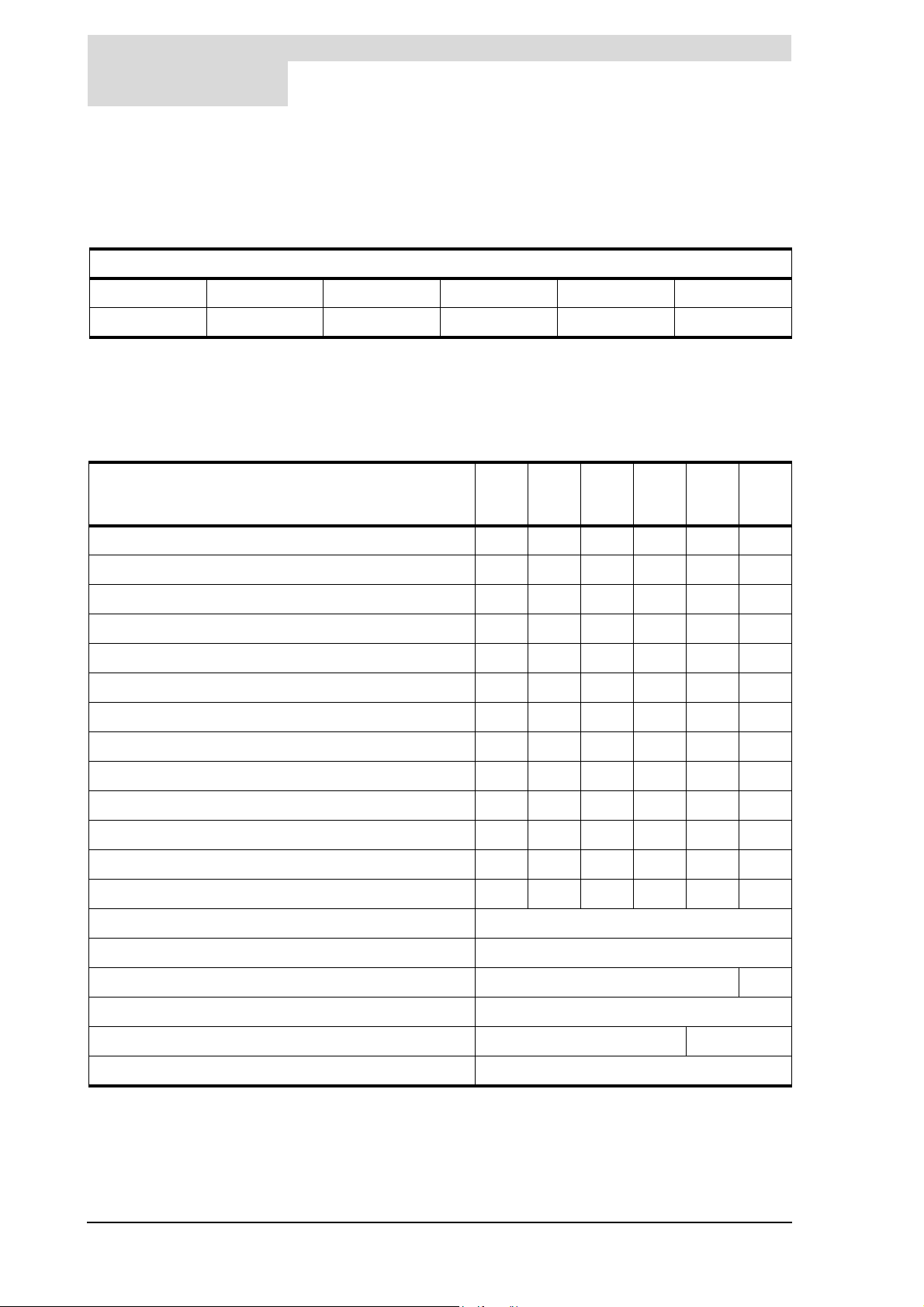
Because of the weight of the water heater when filled (see Ta bl e 3 .2 ), verify that
the maximum floor loading for the boiler room is not exceeded.
Table 3.2 Weight specifications with regard to maximum floor loading
Weight of the water heater filled with water
DR-LP 30 DR-LP 40 DR-LP 45 DR-LP 60 DR-LP 75 DR-LP 95
504 kg 578 kg 507 kg 573 kg 522 kg 523 kg
3.4 Technical
specifications
Table 3.3 Dimensions DR-LP
Dimension & Description DR-
A. Height including draught diverter (mm) 1900 2100 1900 20402025 2085
B. Height excluding draught diverter (mm) 1760 1960 1760190017951810
D. Diameter of the water heater (mm) 710 710 710 710 710 710
E. Depth including control column (mm) 800 800 800 80 0 800 800
F. Width of water heater incl. draught diverter (mm) 1100 110011001100 1105 1105
G. Flue gas outlet diameter (mm) 150 150 180 180 225 225
J. Height flue gas discharge (mm) 1840 2040 1840 2040 1935 2010
K. Height of the gas connection (mm) 205 205 205
M. Height of the cold water supply (mm) 565 565 565 505575590
N. Height of the hot water outlet (mm) 1605 1810 1605 1750 1640 1655
The water heater is supplied without accessories. Check the dimensions and
other specifications for any accessories to be used against Figure 3.1 and
tables Ta bl e 3 .3 through Ta bl e 3 .6 .
LP
30
DRLP
40
DRLP
45
DRLP
60
205205205
DRLP
75
DRLP
95
P. Height of the cleaning opening centre (mm) 730730730 670 740 765
R. Height of the drain valve centre (mm) 500 515 500 455 525 540
S. Height of the T&P plug centre (mm) 1550 1760 1550 1700 15951600
1. Cold water supply connection (external thread) R 1
2. Hot water outlet connection (internal thread) Rp 1 1/
3. Gas control connection (internal thread) Rp 3/
4. Drain valve connection (internal thread) Rp 1 1/
5. T&P valve connection (internal thread) 1" NPT 1" NPT
6. Dimension of cleaning and inspection openings (mm) Ø 100
1
/
2
2
Rp 3/
4
2
4
20 Instruction manual DR-LP
Page 21
is
Technical specifications
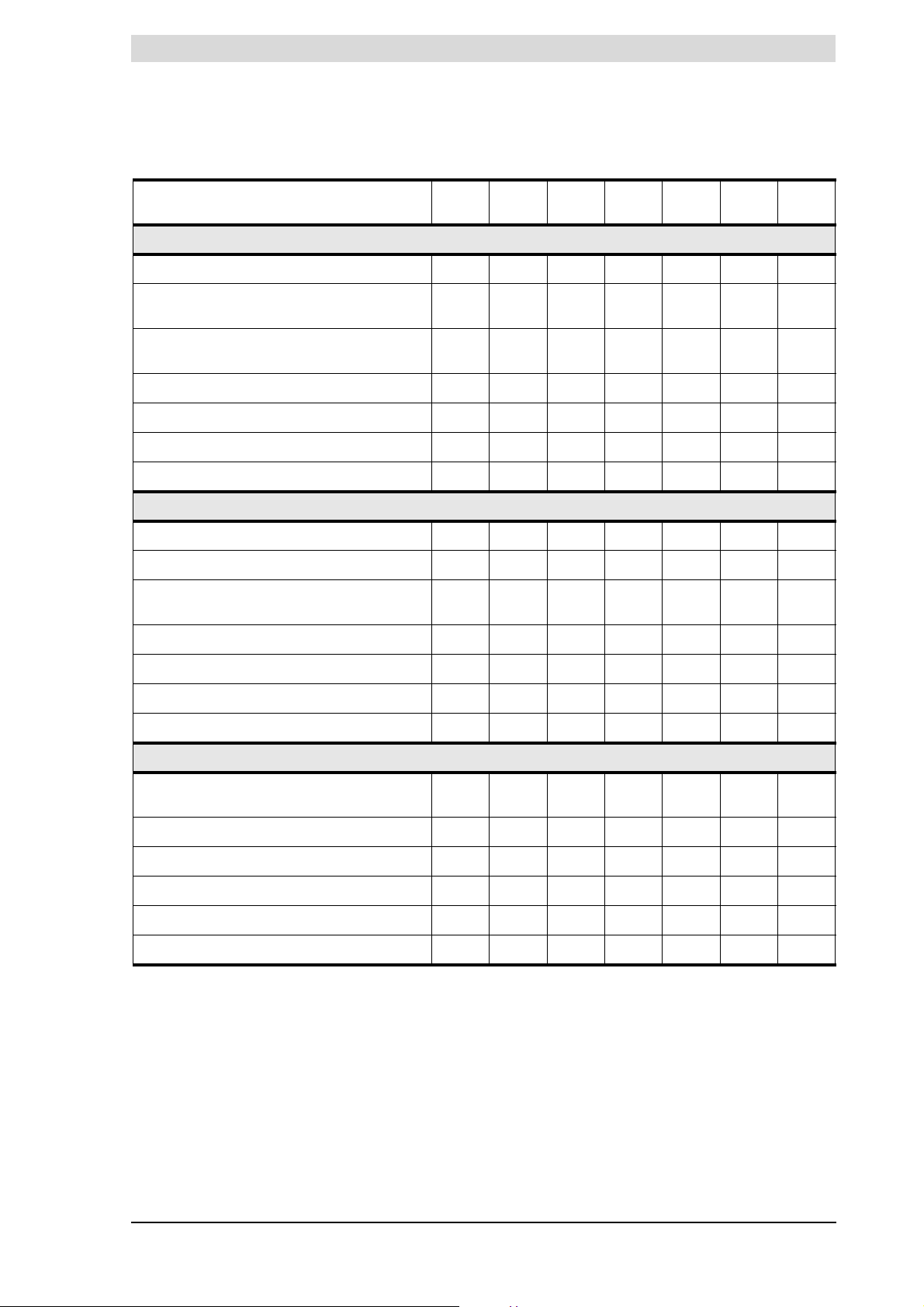
Tab le 3.4 Specifications for gas categories, water heater category: II
Description Unit DR-LP30DR-LP40DR-LP45DR-LP60DR-LP75DR-LP
Gas category 2H: G20 - 20 mbar
Diameter of orifices mm 3.20 3.20 3.10 2.95 3.20 3.20
Diameter of pilot flame orifice mm 0.56/
0.41
(1) = Blanking plate
(2) = Burner pressure regulator
Nominal load (gross) kW 41.4 55.4 65.2 81.0 96.4 124.2
Nominal output kW 31.7 41.9 49.3 61.2 72.9 93.9
Burner pressure
Gas consumption
Gas category 3+: G30 - 30 mbar
Diameter of orifices mm 1.70 1.70 1.70 1.50 1.7
Diameter of pilot flame orifice mm 0.25 0.25 0.25 0.25 0.25 0.25
(1) = Blanking plate
(2) = Burner pressure regulator
(1)
(2)
1 or 2222222
mbar8.58.58.58.58.58.5
m³/h 4.0 5.4 6.3 7.9 9.4 12.1
1 or 2111111
2H3+
0.56/
0.41
0.56/
0.41
0.56/
0.41
0.56/
0.41
0 1.70
95
0.56/
0.41
Nominal load (gross) kW 40.9 54.2 66.9 79.2 94.3 121.2
Nominal output kW 32.0 42.0 51.8 61.4 73.1 93.9
Burner pressure
Gas consumption
Gas category 3+: G31 - 37 mbar
(1) = Blanking plate
(2) = Burner pressure regulator
Nominal load (gross) kW 37.6 50.1 62.1 76.2 87.8 110.9
Nominal output kW 29.4 38.7 48.0 58.9 67.9 85.7
Diameter of orifices mm 1.70 1.70 1.70 1.50 1.7
Burner pressure
Gas consumption
1. If using a blank plate instead or burner pressure regulator, it is assumed that the burner pressure is equal to the supply
pressure. In practice however the burner pressure will be lower
2. Based on 1013.25 mbar and 15°C
(1)
(2)
(1)
(2)
mbar------
kg/h 3.0 4.0 5.0 5.9 7.0 9.0
1or 2111111
0 1.70
mbar------
kg/h 2.7 3.7 4.5 5.6 6.4 8.1
Instruction manual DR-LP 21
Page 22
3
Installation
is
Tab le 3.5 General and electrical data
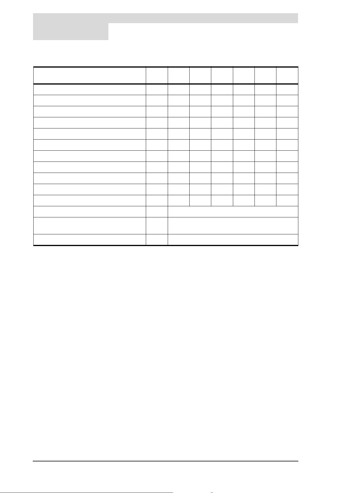
Description Unit DR-LP30DR-LP40DR-LP45DR-LP60DR-LP75DR-LP
95
Storage Capacity litres 324 374 312 351 291 265
Maximum operating pressure bar888888
Maximum operating pressure unvented bar 5,5 5,5 5,5 5,5 5,5 5,5
Nominal operating pressure unvented bar 3,5 3,5 3,5 3,5 3,5 3,5
Number of anodes - 222334
Empty Weight kg 195 221 209 238 244 270
Heating time T = 45°C min. 32 28 20 18 13 9
Number of anodes - 334477
Number of bar burners/orifices - 3 45779
Number of flue tubes/baffles - 5 6 7 9 12 16
Electrical power consumption W 30
Supply voltage ACS
(VAC)
Mains frequency Hz 50 (±1 Hz)
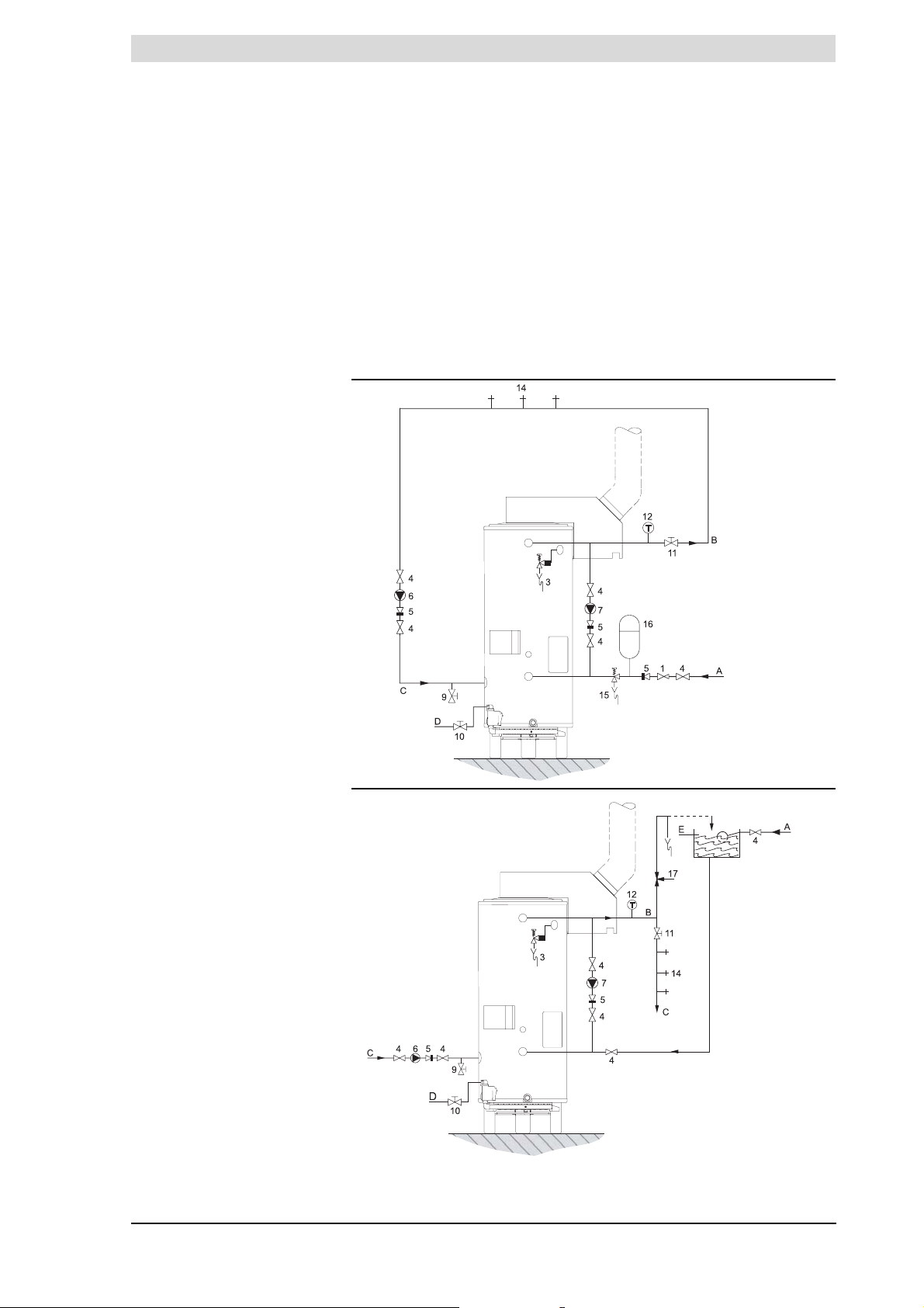
3.5 Installation diagrams Figure 3.2 shows the water and gas connection diagrams for unvented and
vented installations. The following paragraphs, describing the connections in
detail, make reference to these diagrams.
3.6 Water connections
Unvented
3.6.1 Cold water side
See a in Figure 3.2.
1. Fit an approved stop valve i on the cold water side as required by
regulations.
See also paragraph 1.3 Regulations.
2. The maximum working pressure of the water heater is 8 bar. The expansion
valve regulates the pressure to 5.5 bar. The operatiing pressure is 3.5 bar.
Fit an approved pressure-reducing valve a.
3. Fit a non-return valve e and an expansion vessel b.
4. Fit an expension valve n and connect the discharge to a drain via tundish.
230 (-15% +10%)
3.6.2 Top to bottom recirculating pump
You can connect a top to bottom recirculation pump to prevent stratification of
the water in the water heater.
1. Fit a pipe (Ø 22 mm), a stop valve d and a top to bottom recirculation
pump k.
2. Fit non-return valve e.
3. Fit stop valves i.
22 Instruction manual DR-LP
Page 23
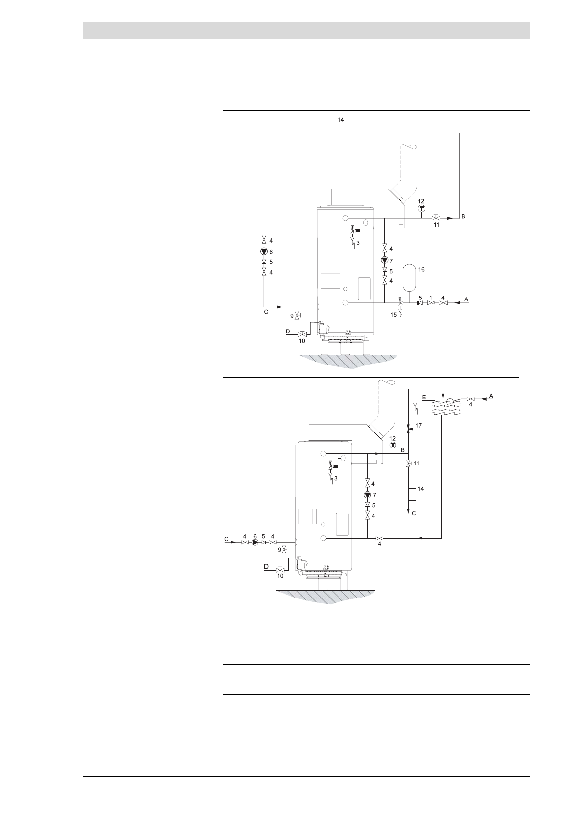
is
Legend
a pressure-reducing valve
(mandatory)
b expansion vessel (mandatory)
c T&P valve (mandatory)
ca) safety valve
d stop valve (recommended)
e non-return valve (mandatory)
ea) non-return valve
f circulation pump (optional)
g drain valve
h gas valve (mandatory)
i stop valve (mandatory)
j temperature gauge
(recommended)
k top to bottom recirculation
pump (optional)
l draught diverter
m hot water draw-off points
n expension valve (mandatory)
o water tank
p float valve
q 3-way venting valve (optional)
r overflow pipe
a cold water supply
b hot water outlet
c circulation pipe
d gas supply
e flue gas discharge
Water connections Unvented
UNVENTED
IMD-0314
VENTED
IMD-0315
Figure 3.2 Installation diagrams
3.6.3 Hot water side
See b in Figure 3.2.
n Note
Insulating long hot water pipes prevents unnecessary energy loss.
1. Optional: fit a temperature gauge j to be able to check the temperature of
the tap water.
2. Fit the T&P valve c.
Instruction manual DR-LP 23
Page 24
3
Installation
is
3. Fit a stop valve i in the hot water outlet pipe, for use when servicing.
3.6.4 Drain valve
1. Fit the standard drain valve g supplied.
2. Refer to paragraph 3.6.5 if a circulation pipe is to be fitted. Otherwise, fit the
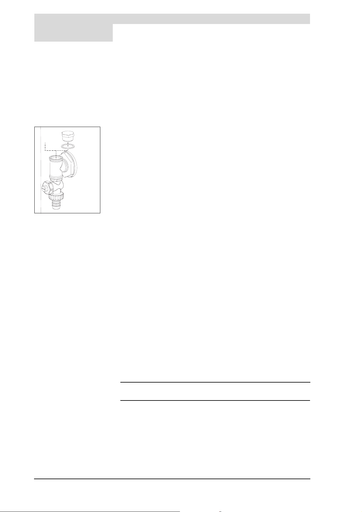
sealing nut and gasket supplied with the drain valve. See Figure 3.3.
3.6.5 Circulation pipe
See c in Figure 3.2. and Figure 3.3.
If an immediate flow of hot water is required at draw-off points, a circulation
c
pump can be installed. This improves comfort and reduces water wastage.
1. Fit a circulation pump f of the correct capacity for the length and resistance
of the circulation system.
2. Fit a non-return valve ea downstream the circulation pump to guarantee
the direction of circulation.
3. Fit two stop valves for servicing d.
4. Connect the circulation pipe to the T-piece on the drain valve g. See
Figure 3.3.
IMD-0122
Figure 3.3 Drain valve
3.7 Water connections
Vented
3.7.1 Cold water side
3.7.2 Top to bottom recirculating pump
3.7.3 Hot water side
See a in Figure 3.2.
• Fit an approved stop valve (recommended) on the cold water side between
the water tank o and the water heater i as required by regulations. Ideally
the vent pipe should be linked to a separate tundish/drain or else to the cold
water storage tank. See also paragraph 1.3 Regulations.
You can connect a top to bottom recirculation pump to prevent stratification of
the water in the water heater.
1. Fit a pipe (Ø 22 mm), a stop valve d and a top to bottom recirculation
pump k.
2. Fit non-return valve e.
3. Fit stop valves i.
See b in Figure 3.2.
n Note
Insulating long hot water pipes prevents unnecessary energy loss.
1. Fit the safety valve ca.
2. Optional: fit a temperature gauge (recommended) j to be able to check the
temperature of the tap water.
3. Fit a stop valve (mandatory) i in the hot water outlet pipe, for use when
servicing.
4. Refer to paragraph 3.7.4 if a circulation pipe is to be fitted.
24 Instruction manual DR-LP
Page 25
is
3.8 Gas connection
Gas connection
3.7.4 Circulation pipe
See c in Figure 3.2.
If an immediate flow of hot water is required at draw-off points, a circulation
pump can be installed. This improves comfort and reduces water wastage.
1. Fit a circulation pump f of the correct capacity for the length and resistance
of the circulation system.
2. Fit a non-return valve ea downstream the circulation pump to guarantee
the direction of circulation.
3. Fit two stop valves for servicing d.
4. Connect the circulation pipe to the T-piece on the drain valve g. See
Figure 3.3.
Warning
Gas installation may only be carried out by an authorised installation
engineer in compliance with the general regulations imposed by the gas
company.
See also paragraph 1.3 Regulations.
3.9 Flue gas discharge
3.9.1 Introduction
cCaution
Make sure that the diameter and length of the gas supply pipe is are large
enough to supply sufficient capacity to the water heater.
See d in Figure 3.2.
1. Fit a gas valve (mandatory) h in the gas supply pipe.
2. Blow the gas pipe through before use, to be sure it is clean.
3. Close the gas valve.
4. Fit the gas supply pipe to the gas control.
Warning
Check for leaks after fitting.
Warning
The installation should be carried out by an authorised installation engineer,
in compliance with the general and local regulations imposed by gas, water
supply and power supply companies and the fire service. Refer also to
paragraph 1.3 Regulations and documents.
When connecting the water heater to the chimney, the draught diverter l
supplied with the water heater must be used. The standard flue gas thermostat
and sensor that are supplied must be fitted in the draught diverter.
Instruction manual DR-LP 25
Page 26
3
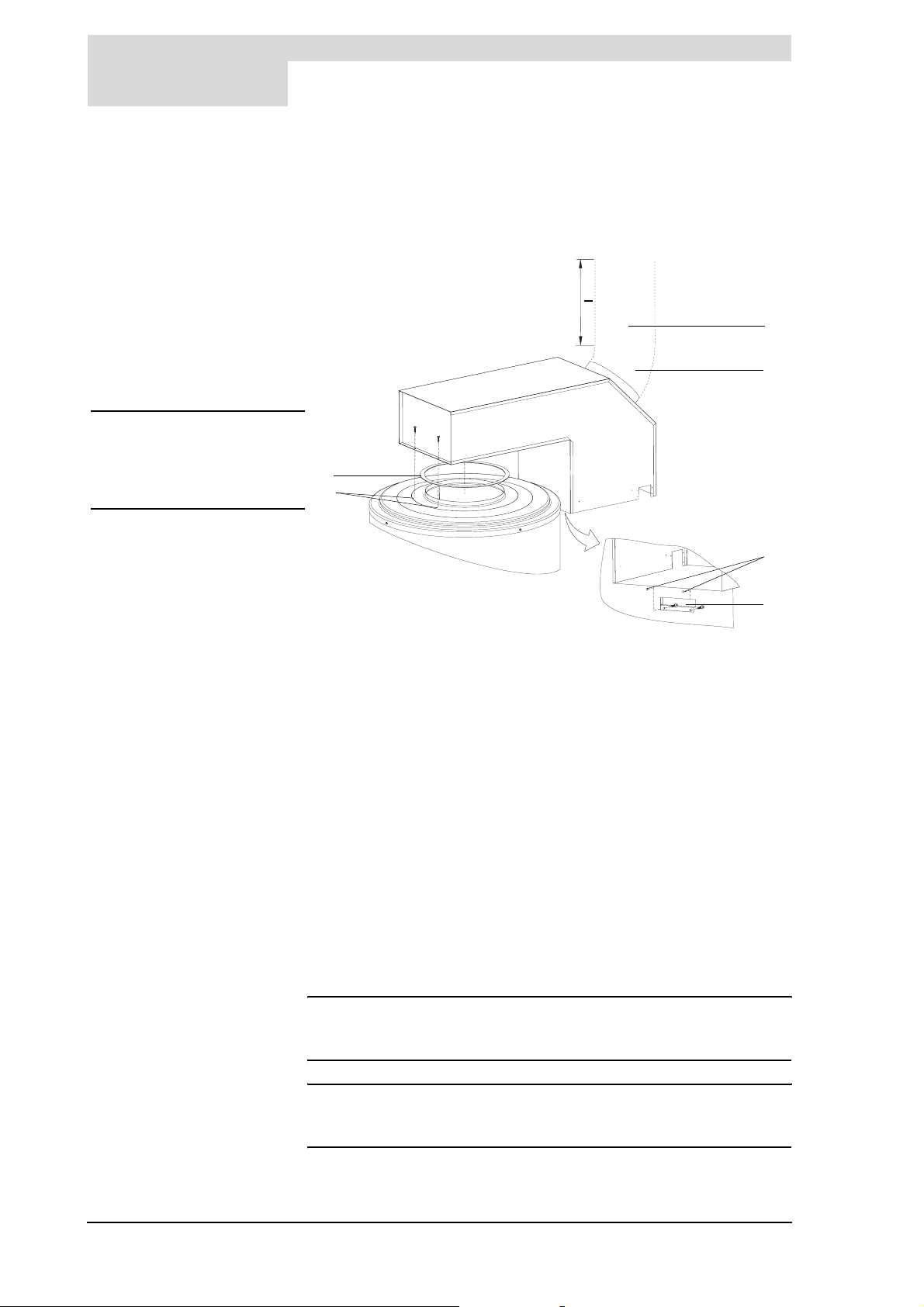
3.9.2 Fitting the draught diverter
Legend
a sealing ring
b fastening screws
c chimney pipe
d 45° bend
e holes to attach support bracket
f support bracket
n Note
To guarantee draught a
chimney pipe with a lenght of at
least 0.5 m should be fitted to
the 45o bend.
Installation
is
The draught diverter can be positioned according to preference. After
positioning, the draught diverter is secured using two screws b to the top
surface of the water heater and also sits on a support bracket f attached to the
side of the water heater. The assembly procedure is as follows:
> 0.5 m
c
d
a
b
e
f
IMD-0123
Figure 3.4 Placing the draught diverter
1. Take the support bracket out of the bag.
2. Fit the support bracket f in such a way that it properly supports the draught
diverter.
3. Drill two holes e (3.2 mm drill) for the support bracket screws.
4. Screw the support bracket tightly to the water heater.
5. Place the draught diverter in the support bracket and mark the centres for
the two drill holes on the top surface of the water heater. Remove the
draught diverter from the water heater.
6. Now drill two holes b into the top of the water heater (3.2 mm drill).
7. Place the sealing ring a on the water heater.
8. Screw the draught diverter tightly in place.
9. Fit:
- a 45° bend d onto the outlet of the draught diverter, followed by:
- a corrosion-resistant vertical chimney pipe c of at least 0.5 metre,
- the remaining flue components.
n Note
Use flue gas discharge materials that comply with the regulations. See
paragraph 1.3 Regulations and documents.
n Note
Make sure that the chimney discharges into an area where this is permitted
for this category of water heater.
26 Instruction manual DR-LP
Page 27
is
Electrical connection
3.9.3 Flue gas thermostat assembly
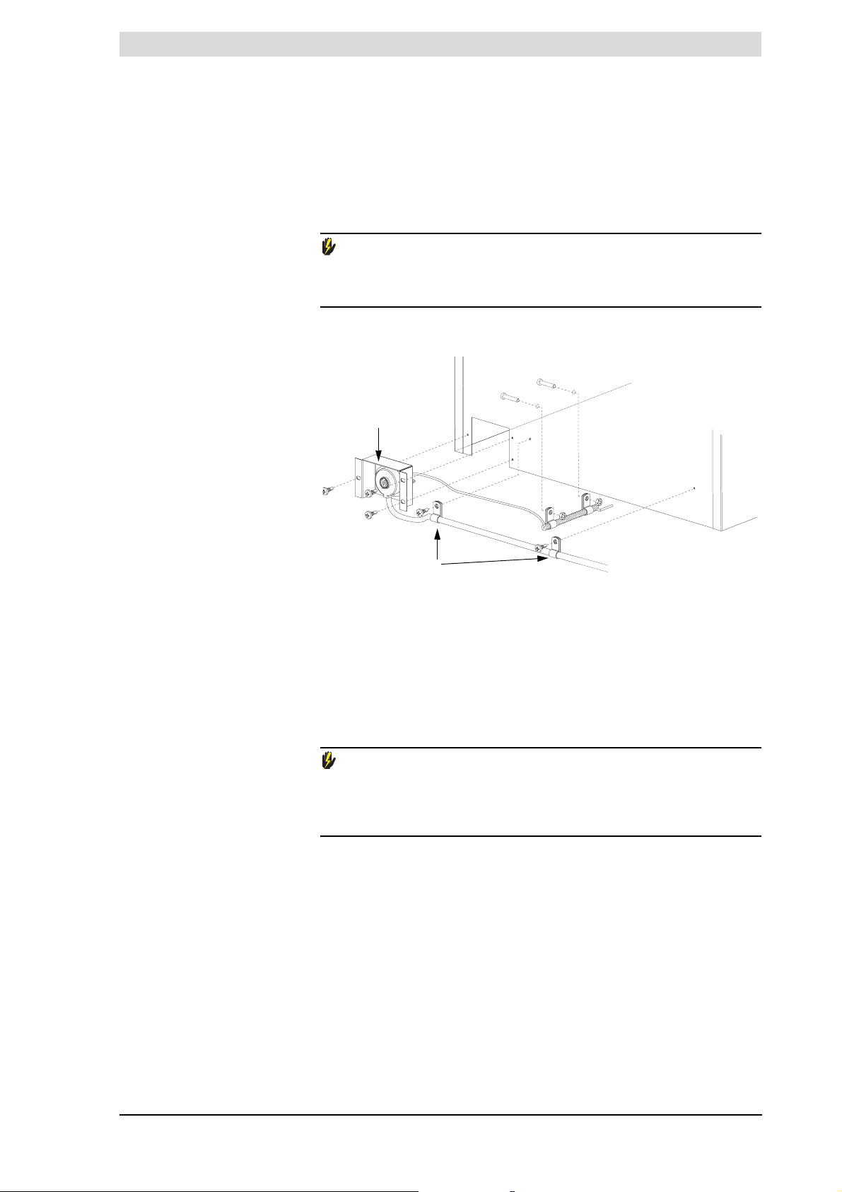
Attached to the control column is a plastic bag containing the flue gas
thermostat with sensor and related attachment materials. The cable from the
sensor is already connected in the control column. The thermostat/bracket and
sensor have yet to be fitted inside the draught diverter. See Figure 3.5.
Warning
If the flue gas thermostat is not (or is incorrectly) fitted/connected, the flue
gas discharge will not be protected. An incorrectly fitted chimney can cause
flue gases to backflow into the boiler room.
2
1
3.10 Electrical
connection
2
4
3
Figure 3.5 Flue gas thermostat assembly
Fit the flue gas thermostat as follows:
1. Take the bracket 1 with thermostat and sensor 2 from the packaging.
2. Place the bracket in the draught diverter and screw the bracket and the
sensor firmly in place.
3. Bend the cable clips 3 around the cable 4 of the flue gas thermostat.
Screw the cable clips 3 in place in the draught diverter and the water heater.
IMD-0137.
Warning
The installation should be carried out by an approved installation engineer
in compliance with the general and local regulations imposed by the gas,
water and power supply companies and the fire service.
See also paragraph 1.3 Regulations.
Instruction manual DR-LP 27
Page 28
3
3.10.1 Introduction
Tab le 3.6 Electrical connecting block DR-LP
Installation
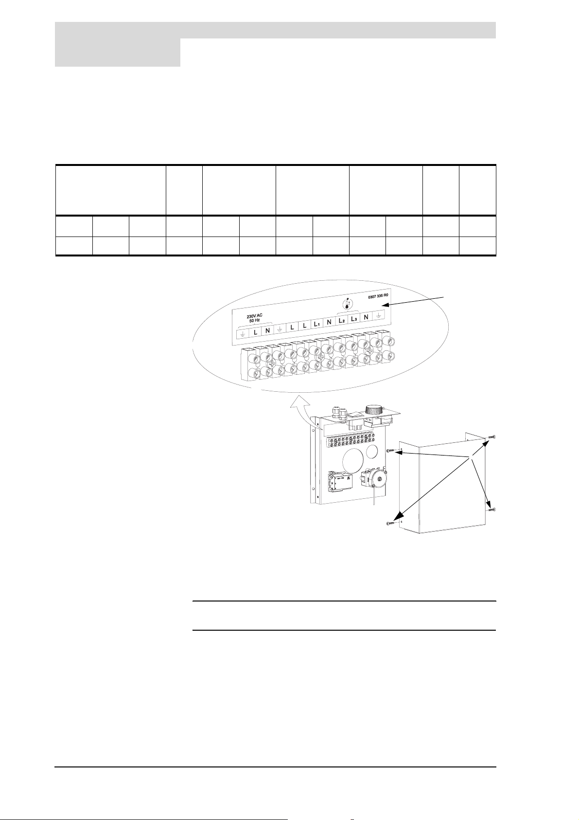
This paragraph covers the connectons of the 3.10.2 Mains power;
Figure 3.6 shows a front view of the electrical connecting block. Table 3.6
shows the associated connections.
is
Mains voltage Time clock
connection
A
123456789101112
LN
A
LLL1NL2L
1
Time clock
power
Combustion
products
discharge
safety device
3
14
N
A
c
a
b
IMD-0366
Figure 3.6 Connecting block (connections 1 to 14 explained in Ta bl e 3 .6 )
In preparation, first remove the protective cover from the control column:
• Undo the 4 screws a and remove the protective cover 2 from the electrical
section. The connecting block 3 is now visible.
n Note
Consult A DR-LP electrical diagram for electrical component connections.
28 Instruction manual DR-LP
Page 29
is
3.10.2 Mains power
The water heater is supplied without a power cable and isolator.
n Note
In order to receive electrical power, the water heater has to be connected to
the mains voltage by means of a permanent electrical connection. A double
pole isolator with contact gaps of at least 3 mm must be fitted local to the
water heater. The power cable must have cores of at least 3 x 1.0 mm2.
1. Feed the power cable through the metric strain relief on the top of the control
column.
2. Connect earth (
terminals 1 to 3 of the connecting block as set out in Ta bl e 3 .6 .
3. Tighten the strain relief so that the cable is clamped.
4. If you do not need to make any more connections, then fit the protective cap
on the control column.
5. Connect the power cable to the isolator.
Warning
Leave the water heater disconnected until you are ready to start it up.
A), phase (L
Conversion to a different gas category
) and neutral (N) on the power cable to
1
3.11 Conversion to a
different gas
category
cCaution
The conversion may only by carried out by an authorised installation
engineer.
Instruction manual DR-LP 29
Page 30
3
3.11.1 Introduction
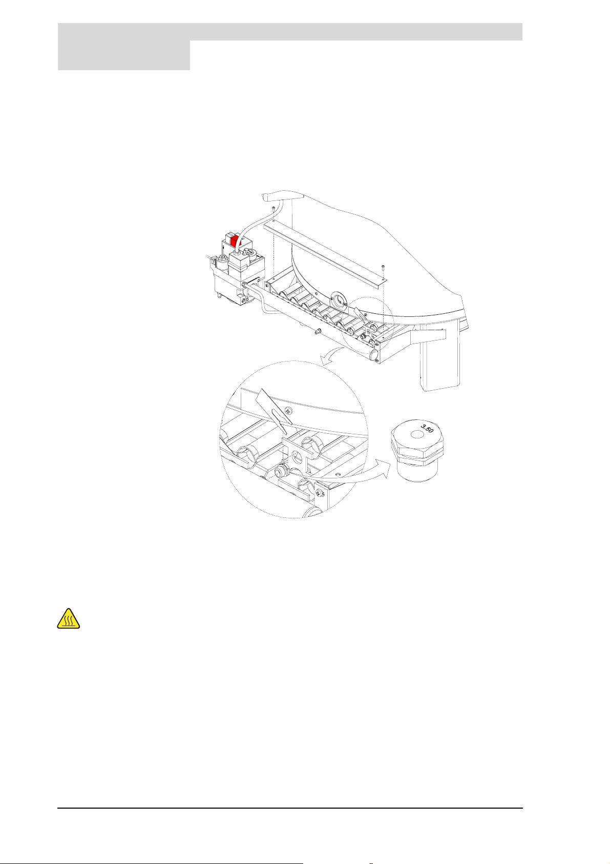
Legend
a cover plate
b locking strip
c orifice with stamped figures
Installation
is
If the water heater must operate on a family of gas (LP-gas or natural gas) other
than the category of gas for which the water heater has been set up at the
factory, the water heater will have be adapted using a special conversion kit.
Converting the DR-LP water heaters is described in 3.11.2 Conversion to a
different gas category.
1
3.11.2 Conversion to a different gas category
Take care
The burner may be
hot.
2
3
IMD-0196
Figure 3.7 Replacing the orifices
1. Disconnect the water heater from the power supply. See paragraph
7.3.2 Isolate the water heater from the power supply.
2. Shut off the gas supply.
3. Unscrew the cover plate a from the burner support.
4. Use a suitable tool to remove the locking strips b. Note: the locking strips
have especially sharp edges.
Withdraw the locking strips straight upwards.
5. The radiation shield / condensation tray can be temporarily loosened to
simplify assembly of the burner.
6. Remove the burners one by one from their brackets at the front. To do this,
you first move them away from you and then downwards. The orifices are
then accessible.
7. Remove the orifices.
8. Select and fit the correct orifices from the conversion kit, by referring to
Ta bl e 3 .4 . The orifice diameter is shown on the orifice by means of stamped
figures c.
30 Instruction manual DR-LP
Page 31
is
Conversion to a different gas category
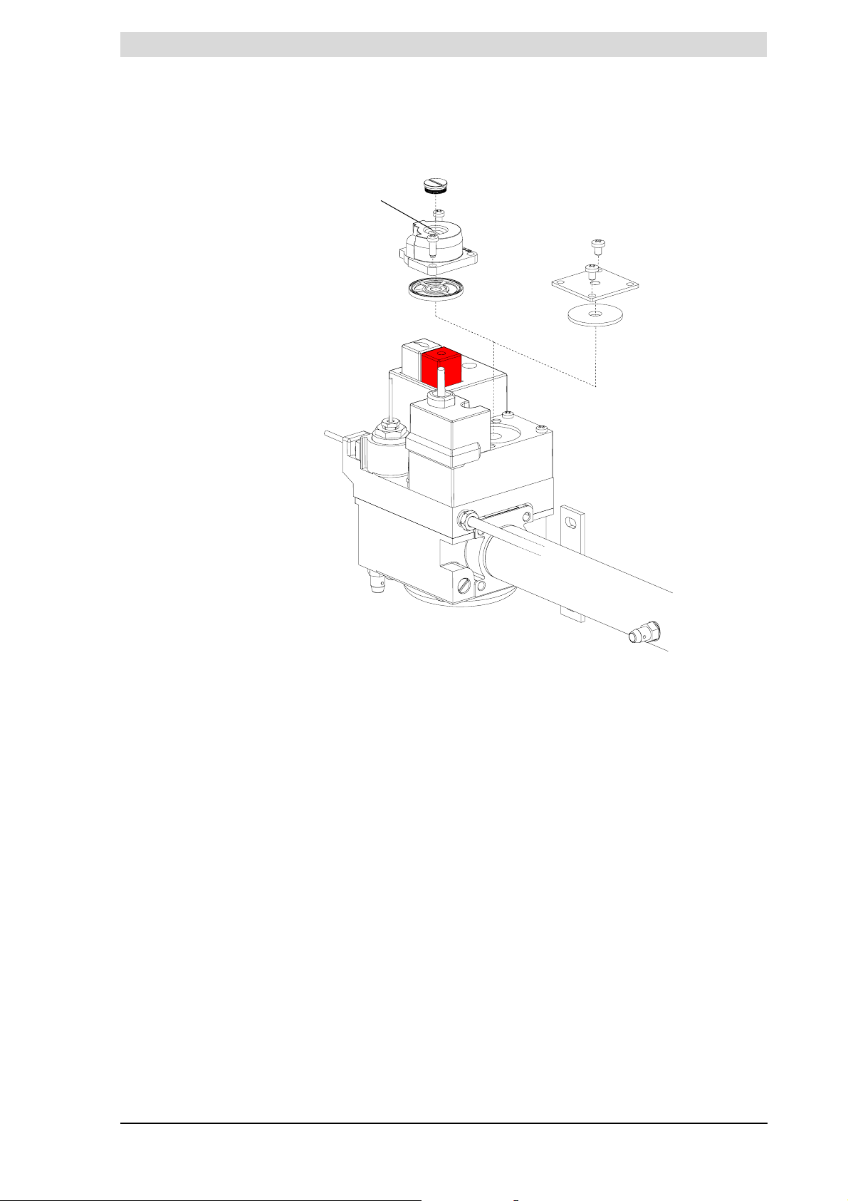
Legend
See Figure 3.7 for 1 to 3.
d burner pressure regulator
e blank plate
f supply pressure test nipple
g burner pressure test nipple
h gas control valve
i burner pressure control cap
j burner pressure control
adjusting screw
i
j
d
e
h
Figure 3.8 Converting the gas control
f
9. Refit the burners back in their original position.
10. Re-fit the locking strips.
11. If the radiation shield /condensation tray was loosened, re-tighten it.
12. Check whether there is a burner pressure regulator d attached to the top of
the gas control or simply a blank plate e.
13. Check with the help of the burner pressure in Table 3.4 whether a burner
pressure regulator is required for the new gas category.
14. If the blank plate must be replaced with a burner pressure regulator or vice
versa:
- Remove the existing blank plate e or burner pressure regulator d.
- Fit the new burner pressure regulator or blank plate supplied with the
conversion kit.
15. Check the burner pressure and supply pressure (see paragraph 3.12).
16. Remove the sticker showing the new gas category from the conversion kit,
attach it below the water heater's rating plate. This clearly indicates that the
water heater may no longer be run on the gas for which it was originally
supplied.
17. Start up the water heater (see paragraph 7.2).
g
IMD-0137
Instruction manual DR-LP 31
Page 32
3
3.12 Checking the supply
pressure and burner
pressure
Installation
is
n Note
Before you start up the water heater and/or begin to check the supply
pressure and burner pressure, you must fill the water heater. For the filling
procedure, please refer to paragraph 4.2 Filling the water heater.
cCaution
Before starting-up for the first time and following conversion, you must
always check the supply pressure and burner pressure. If necessary, adjust
these to be certain of optimum performance of the water heater.
n Note
The easiest way to check the gas pressures is by using two pressure
gauges. This procedure assumes that these two gauges are available.
1. Switch off the power to the water heater and extinguish the pilot flame. See
paragraph 7.3.2 Isolate the water heater from the power supply.
2. The supply pressure is checked using a test nipple f on the gas control
(Figure 3.8). The manifold test nipple g is used for measuring the burner
pressure. Sealing screws are located inside the test nipples. Loosen both
sealing screws by a few turns. Do no completely undo them, as it may be
awkward retightening them.
3. There are two test nipples on the gas control g.
n Note
All gas pipes should be bleeded and free of leakage.
4. Open the gas supply.
5. Connect a pressure gauge to the supply pressure test nipple f as soon as
gas starts to flow from this nipple.
6. Switch on the power to the water heater using the isolator on the water
heater.
7. Begin the ignition procedure by pressing and holding the white button on the
gas control while repeatedly pressing the piezo igniter until the pilot flame
ignites. The pilot flame can be seen through the inspection window above
the burner tray.
8. Keep the white button pressed in for about 30 seconds before carefully
releasing it. The pilot flame must now keep burning.
9. Set the control thermostat to the highest position (take note of the original
setting) and set the On/Off-switch back to position I.
10. If there is no heat demand, then draw-off some hot water to initiate a heat
demand.
11. The heating cycle will start and the burner tray will ignite after a short time.
Warning
If the pilot flame goes out during the ignition procedure or heating cycle, you
must wait 5 minutes before repeating the ignition procedure.
12. After the burner tray has ignited, wait for approximately 1 minute before you
start reading the dynamic pressures.
32 Instruction manual DR-LP
Page 33

is
Checking the supply pressure and burner pressure
13. Use the pressure gauge to read the supply pressure at the test nipple f.
Refer to Ta bl e 3 .4 .
n Note
Consult the mains gas supply company if the supply pressure is not correct.
14. Use the pressure gauge to read the burner pressure at the burner pressure
test nipple. Refer to Tab le 3 . 4.
n Note
If the burner pressure is not correct and the water heater is fitted with a blank
plate (e), you will not be able to adjust the pressure. In this case, consult
your installation engineer or supplier. If the water heater is fitted with a
burner pressure regulator, then the pressure can be adjusted by following
steps 15 to 20.
15. Remove the cap i from the burner pressure regulator d.
16. Adjust the burner pressure by turning the adjusting screw j, depending on
the correction required:
- To reduce burner pressure, turn the adjusting screw anti-clockwise;
- To increase burner pressure, turn the adjusting screw clockwise;
17. Cover the opening of the adjusting screw and check the burner pressure
against the target value from Ta bl e 3 .4 .
18. If the pressure reading is not correct, repeat steps 16 and 17 until the correct
pressure is attained.
19. Re-fit the cap i on the burner pressure regulator.
20. Shut down the water heater by setting the On/Off-switch to the 0 position.
21. Shut off the gas supply.
22. Disconnect the two pressure gauges and re-tighten the sealing screws in the
test nipples.
Instruction manual DR-LP 33
Page 34

3
Installation
is
34 Instruction manual DR-LP
Page 35
gis
gis
4 Filling and draining
4.1 Introduction Topics covered in this chapter:
• Filling the water heater.
• Draining the water heater.
The components referred to in these sections are illustrated in Figure 4.1.
Legend
a pressure-reducing valve
(mandatory)
b expansion vessel (mandatory)
c T&P valve (mandatory)
ca) safety valve
d stop valve (recommended)
e check valve (mandatory)
ea) non-return valve
f circulation pump (optional)
g drain valve
h gas valve (mandatory)
i stop valve (mandatory)
j temperature gauge
(recommended)
k top to bottom recirculation
pump (optional)
l draught diverter
m hot water draw-off points
n expension valve (mandatory)
o water tank
p float valve
q 3-way venting valve (optional)
r overflow pipe
a cold water supply
b hot water outlet
c circulation pipe
d gas supply
e flue gas discharge
UNVENTED
VENTED
Introduction
IMD-0314
IMD-0315
Figure 4.1 Connection diagrams
Instruction manual DR-LP 35
Page 36

4
4.2 Filling the water
heater
Filling and draining
gis
4.2.1 Filling unvented installations
To fill the water heater, proceed as follows.
1. Open the stop valve i on the hot water pipe and, if present, the stop
valves d for the circulation pump.
2. Close the drain valve g.
3. Open the nearest hot water draw-off point m.
4. Open the stop valve i on the cold water side a so that cold water flows into
the water heater.
5. Completely fill the water heater (when cold water flows at normal pressure
from the nearest hot water draw-off point, the water heater is full).
6. Vent the entire installation of air, by opening all hot water draw-off points, for
example.
7. The water heater is now under water supply pressure. There should be no
water coming out of the expansion valve n nor the T&P-valve c. If this does
happen, the cause might be:
- The water supply pressure is greater than the specified 3.5bar.
Check the correct pressure.
- The expansion valve in the cold water supply arrangement is defective
or incorrectly fitted.
4.2.2 Filling vented installations
4.3 Draining the water
heater
4.3.1 Draining unvented installations
To fill the water heater, proceed as follows:
1. Open the stop valve i on the hot water pipe and, if present, the stop
valves d for the circulation pump.
2. Close the drain valve g.
3. Open the nearest hot water draw-off point m.
4. Open the stop valve i on the cold water side a so that cold water flows into
the water heater.
5. Completely fill the water heater (when cold water flows at normal pressure
from the nearest hot water draw-off point, the water heater is full).
6. Vent the entire installation of air, by opening all hot water draw-off points, for
example.
7. The water heater is now under water supply pressure. There should be no
water coming out of the T&P-valve ca. If this does happen, the safety valve
might be defective or incorrectly fitted.
For some procedures may require the water heater to be drained. Proceed as
follows:
Some service activities require the water heater to be drained. The procedure
is as follows:
1. Shut the water heater down by putting the On/Off switch to position 0.
2. Disconnect the water heater by putting switching the mains isolator off.
3. Shut off the gas supply h.
4. Close the stop valve i in the hot water pipe.
5. Close the supply valve in the cold water supply a.
36 Instruction manual DR-LP
Page 37

gis
Draining the water heater
6. Open the drain valve g.
7. Vent the water heater (or installation) so that it drains completely.
4.3.2 Draining vented installations
For some procedures may require the water heater to be drained. Proceed as
follows:
Some service activities require the water heater to be drained. The procedure
is as follows:
1. Shut the water heater down by putting the On/Off switch to position 0.
2. Switch the mains isolation off.
3. Shut off the gas supply h.
4. Close the stop valve i in the hot water pipe.
5. Close the stop valve between the water tank and the cold water inlet.
6. Open the drain valve g.
Instruction manual DR-LP 37
Page 38

4
Filling and draining
gis
38 Instruction manual DR-LP
Page 39
gis
gis
5 Controls
5.1 Introduction Topics covered in this chapter:
• 5.2 Control panel;
• 5.3 Explanation of the symbols;
• 5.4 On/Off-switch;
• 5.5 Control thermostat;
• 5.6 Flue gas thermostat reset button.
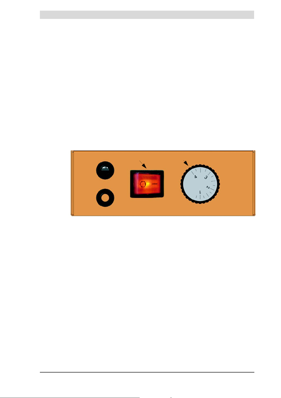
5.2 Control panel Figure 5.1 illustrates the control panel. The panel consists of:
• an On/Off-switch;
• a control thermostat with rotary knob.
ab
Introduction
Figure 5.1 The control panel
Instruction manual DR-LP 39
Page 40
5
Controls
gis
5.3 Explanation of the
symbols
5.4 On/Off-switch Using the On/Off-switch, set the water heater to the ON mode ('I' position) or
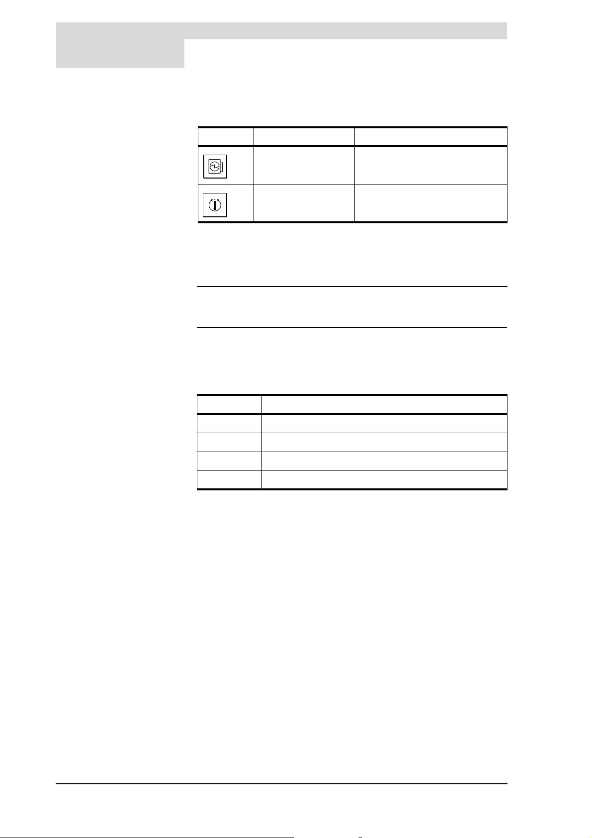
Table 5.1 explains the icons on the control panel.
Table 5 . 1 Control panel icons
Symbol Name Explanation
On/Off switch Sets water heater mode to 'ON',
Temperature control Sets water temperature (T
OFF mode ('0' position). The water heater remains live, even when in the OFF
mode. This keeps the weekly water heating program and/or Power Anode
active.
'Week Program' or 'OFF'.
set
)
n Note
To electrically isolate the water heater, you must use the local switch
between the water heater and the mains power supply.
5.5 Control thermostat Use the rotary knob on the control thermostat to set the desired water
temperature to between 40°C and 70°C. The knob rotates over a scale of 1 to
4. Ta bl e 5 . 2 shows the approximate temperature at each position.
Table 5 . 2 Temperature settings
5.6 Flue gas thermostat
reset button
Position Temperature
1
2
3
4
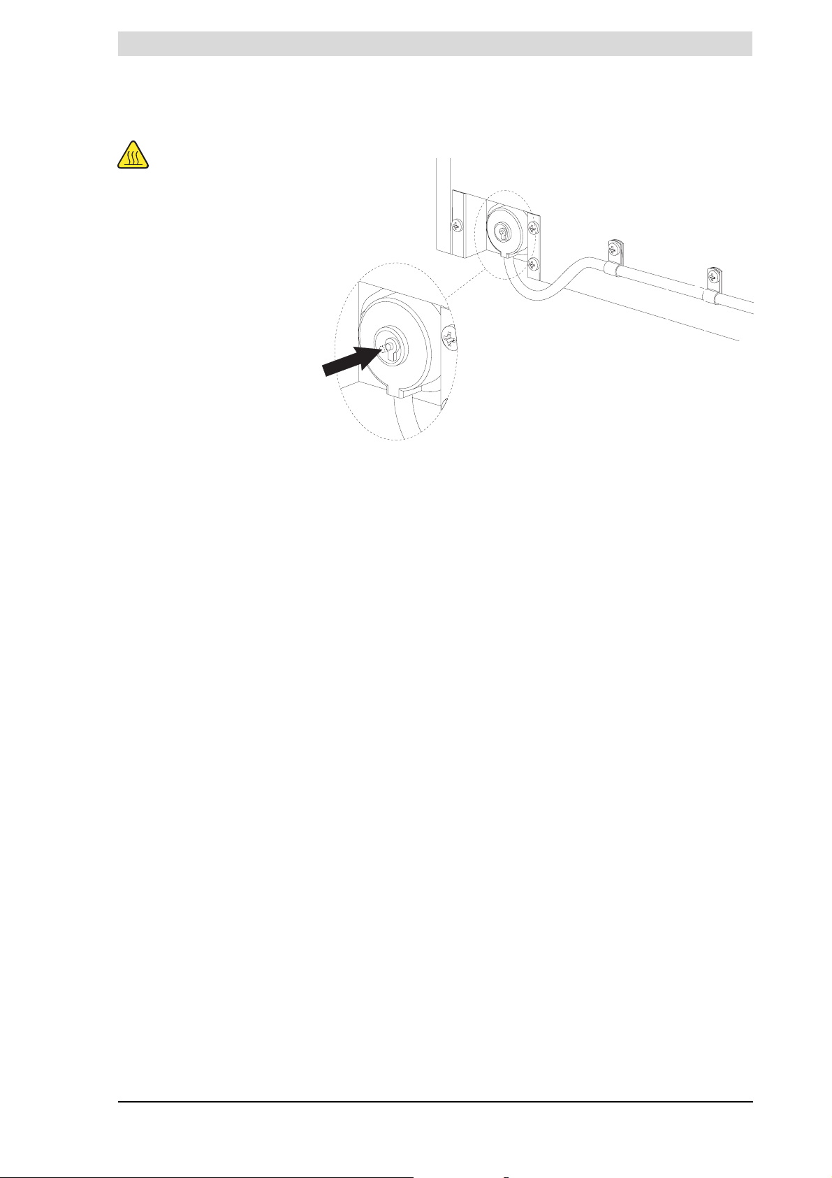
A malfunction in the flue gas discharge, e.g. a blockage in the chimney, can lead
to the flue gas thermostat locking out. This state is evident when the push button
on the flue gas thermostat has been activated, see Figure 5.2. Once the cause
has been removed and the sensor has cooled down sufficiently, press this push
button to reset (if the sensor is not sufficiently cooled down, the flue gas
thermostat will immediately lock out again). The water heater will then
automatically start up again, if there is a demand. If this does not happen, refer
to chapter 8 Troubleshooting for a complete troubleshooting guide.
≈ 40°C
≈ 50°C
≈ 60°C
≈ 70°C
40 Instruction manual DR-LP
Page 41
gis
Take care
The draught diverter
can be hot.
Flue gas thermostat reset button
Figure 5.2 Flue gas thermostat reset button
Instruction manual DR-LP 41
Page 42

5
Controls
gis
42 Instruction manual DR-LP
Page 43

Error states
gis
gis
6 Error states of the
water heater
6.1 Error states If the water heater has an error the heater will not operate. The frost protection
will also be out of operation.
If the water heater should go into an "error" state, you will be unable to
continuosly draw hot water. These error conditions are divided into three
groups:
• Gas control lock out errors
In this case the gas control's safety valve is closed, as a result of which the
pilot flame is extinguished. Once this error has been rectified, the pilot flame
must be re-lit. See paragraph 7.2 Starting up.
• Blocking error due to high limit thermostats
You can recognise this status by the fact that the water heater will not start
operation, despite the water temperature being lower than you have set with
the control thermostat (see 5.5 Control thermostat).
This error disappears automatically once the high limit thermostat resets
itself, after which the water heater re-starts.
• Lock out error due to the combustion products discharge safety
device
This error state has much the same characteristics as a 'Blocking error'. The
difference here is that the lock out (push button) for the flue gas thermostat
in the draught diverter is activated. See paragraph 5.6 Flue gas thermostat
reset button. After removing the cause, the push button must be pressed to
allow the water heater to automatically re-start.
The cause of the error cannot be seen on the control panel. Please refer to
chapter8 Troubleshooting for a detailed overview of error states.
If you find the water heater in a fault state, as an end user you can attempt to
re-start the water heater, see paragraph '7.2 Starting up
However, should the error return or become persistent, you should contact your
service engineer.
Instruction manual DR-LP 43
Page 44

6
Error states of the water heater
gis
44 Instruction manual DR-LP
Page 45
gis
gis
7 Starting up and
shutting down
7.1 Introduction Topics covered in this chapter:
• Starting up;
• Shutting down.
Introduction
b
a
c
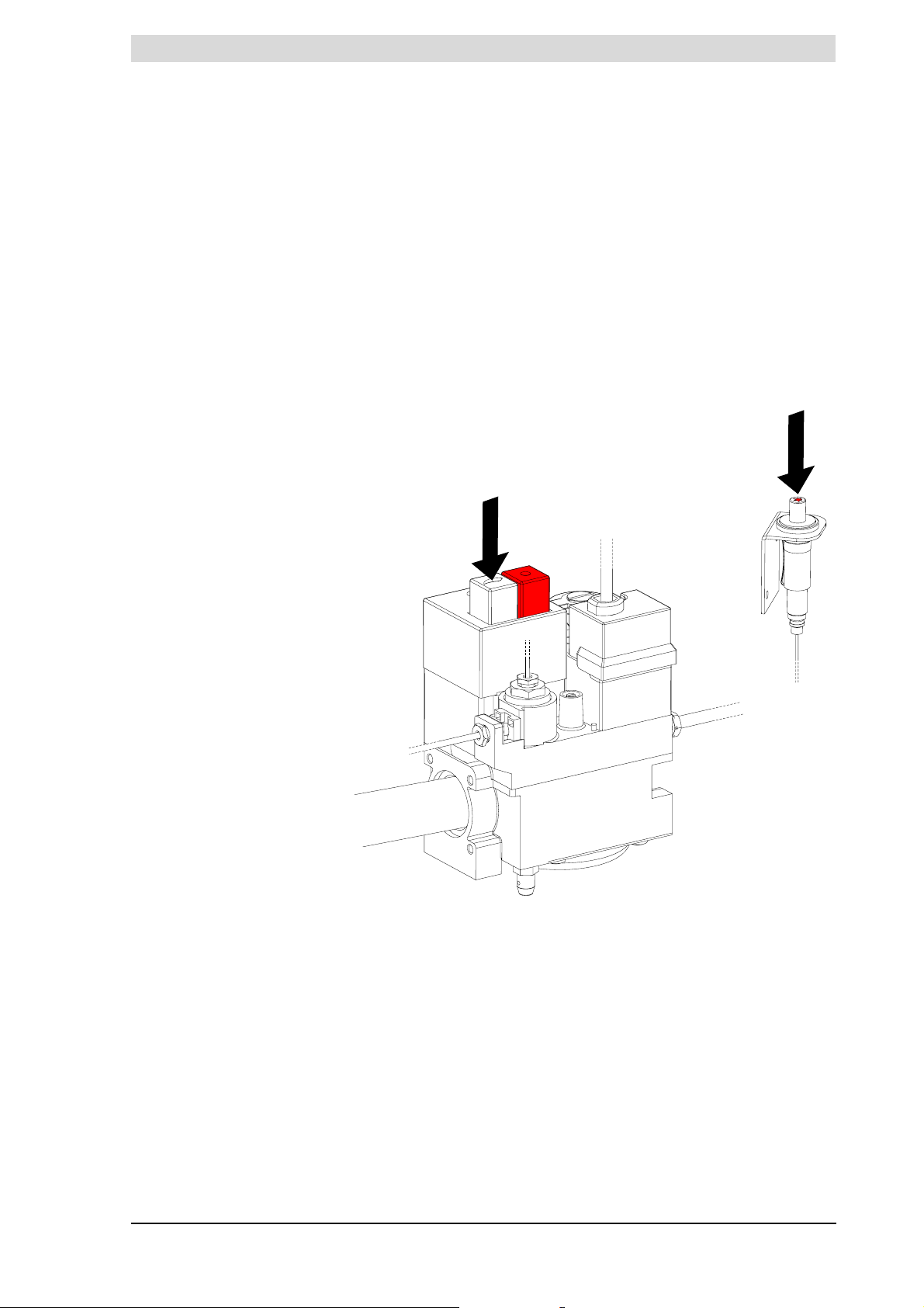
Figure 7.1 Gas control
7.2 Starting up Start-up the water heater as follows:
1. Fill the water heater. See chapter 4 Filling and draining.
2. Open the manual gas valve. See Figure 4.1 Connection diagrams.
3. Switch on the power to the water heater using the isolator between the water
heater and the power supply.
IMD-0195
Instruction manual DR-LP 45
Page 46
7
7.3 Shutting down You c an :
Starting up and shutting down
4. Begin the ignition procedure by pressing and holding the white button a on
the gas control while repeatedly pressing the piezo igniter b until the pilot
flame ignites. See Figure 7.1. The pilot flame can be viewed through the
inspection window above the burner tray.
Warning
If the pilot flame goes out during the ignition procedure or warm-up cycle,
you must wait 5 minutes before repeating the ignition procedure.
5. Keep the white button pressed in for about 30 seconds before carefully
releasing it. The pilot flame should now stay lit.
6. Switch the water heater to the 'ON mode' by switching the On/Off-switch on
the control panel to the Iposition.
7. Set the desired water temperature using the control thermostat. See
paragraph 5.5 Control thermostat.
If there is a heat demand, the heating cycle will run its course. See paragraph
7.4 Heating cycle'.
• Shut the water heater down for brief periods ("OFF mode").
• Isolate the water heater from the power supply.
• Shut the water heater down for a longer period.
gis
7.3.1 Shut the water heater down for brief periods ("OFF mode")
To shut down the water heater for a brief period, you can set the water heater in
"OFF-mode". Activate frost protection by switching the On/Off-switch on the
control panel to the 0 position. The pilot flame will remain on.
7.3.2 Isolate the water heater from the power supply
When servicing, the water heater must be electrically isolated. The correct
procedure is as follows:
1. Put the water heater in OFF mode by switching the On/Off-switch to the
0 position.
2. Switch off the power to the water heater by switching the isolator between
the water heater and the mains power supply to position 0.
3. The pilot flame will remain on, but you can extinguish it if required by
pressing the red button c on the gas control. See Figure 7.1.
cCaution
These operating states of "OFF mode" and "Isolated" are advisable only if
there is no risk of frost. If frost can be expected, you will need to drain the
water heater, see paragraph 7.3.3 Shut the water heater down for a longer
period.
7.3.3 Shut the water heater down for a longer period
Drain the water heater if you are shutting it down for a longer period of time.
Proceed as described in paragraph 4.3 Draining the water heater.
7.4 Heating cycle The heating cycle is activated as soon as the measured water temperature
falls below the threshold value (Tset). Tset can be adjusted using the
(T
water)
control thermostat, for example position 3 (60°C).
The heating cycle runs in turn through the following states:
1. HEAT DEMAND;
2. IGNITION;
46 Instruction manual DR-LP
Page 47

gis
Heating cycle
3. RUNNING;
The complete cycle is explained in the example set out below.
1. The control thermostat sensor measures the water temperature (T
T
drops below the set temperature (T
water
the control thermostat will close. This will cause the gas control to open.
2. Once the gas control is open, the pilot burner will ignite the gas flow.
3. The water heater is now running. This means that actual heating has started.
When the water is up to temperature, the heat demand cuts out. The gas
control closes and the burner tray is extinguished (the pilot flame stays lit).
4. The water heater is now said to be in a state of rest and waiting until T
once again falls below T
With any subsequent heat demand, the heating cycle will resume from step 1.
set
.
), there is a heat demand and
set
water
). If
water
Instruction manual DR-LP 47
Page 48

7
Starting up and shutting down
gis
48 Instruction manual DR-LP
Page 49

gis
8 Troubleshooting
8.1 Introduction This chapter covers the following errors:
General errors
- Gas smell.
- Water leakage.
- Explosive ignition.
- Poor flame profile.
- Power Anode (optional)
• No hot water
• Insufficient hot water.
General errors cannot be displayed on the control panel, but these errors
usually do not cause the hot water supply to fail, neither fully nor partially.
If the hot water supply should fail, this is termed an error state. See paragraph
6.1 Error states'.
If the hot water supplied is insufficient, this is usually caused by an incorrect
setting or some temporary problem.
The following pages provide troubleshooting tables for each type of error.
Instruction manual DR-LP 49
Page 50
is
Immediately contact your installer or local gas company.
n Note
Warning
Immediately close the main gas valve.
Warning
Maintenance should only be carried out by a qualified service and maintenance engineer.
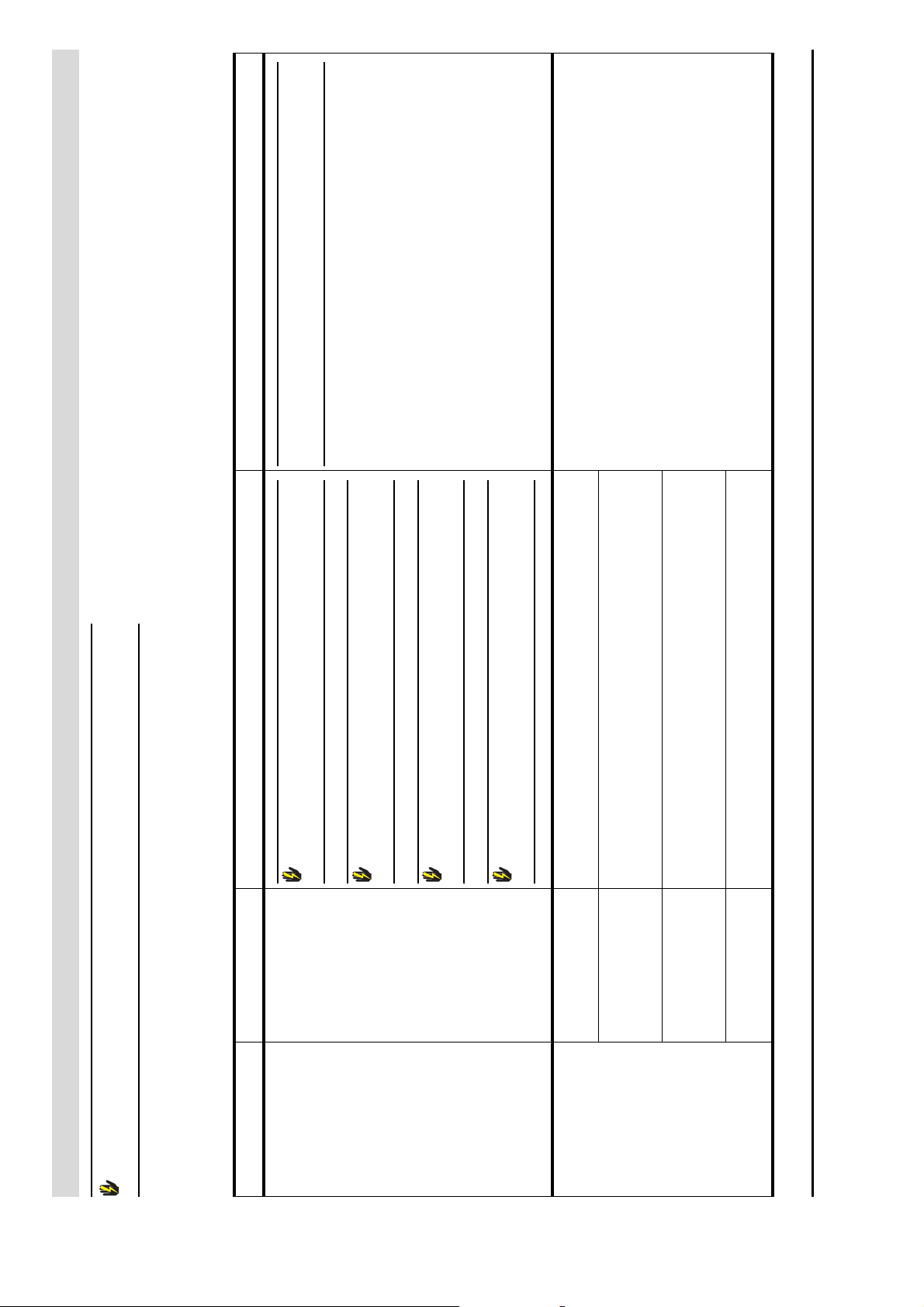
8.2 Troubleshooting table for general errors
Table 8 . 1 General errors Page 1 of 2
Symptom Cause Solution Remarks
Gas smell Gas leak
Warning
Do not operate any switches.
Warning
No naked flames.
Warning
Ventilate the room where the water heater is located.
Tighten the threaded connection. If the leak has not been repaired, consult your installer.
Water leakage Leakage from a water
Trace the leak.
connection (threaded).
Leakage from another
water water heater or
Consult the supplier and/or manufacturer.
pipe nearby.
Leakage from the
water heater's hot
the heater has reached the set temperature.
water tank.
Condensation Before drawing off hot (too much) tap water, wait until the water in
Release R.2.0 Uk 50
Page 51
is
If ignition is not improved, consult your installer.
Set the correct supply pressure and/or burner pressure, see
3.12 Checking the supply pressure and burner pressure.
water heater is located.
If the error cannot be corrected, consult your installer.
'appendix A DR-LP electrical diagram';
1. Check that the water heater is full of water;
2. Check that the Power Anode is properly connected, see
3. Check to see that all connections are properly made;
4. Check all cables for breaks and replace if any are found.
Check the power supply
contact with the
water;
cables;
earthed;
Incorrect supply
pressure and/or burner
pressure.
Contaminated burner Clean the burner. See 9.4.2 Cleaning the burners
Contaminated injector Clean the injector. See 9.4.3 Cleaning the injectors
Inadequate air supply Improve the air supply by better ventilating the room in which the
Warning
Maintenance should only be carried out by a qualified service and maintenance engineer.
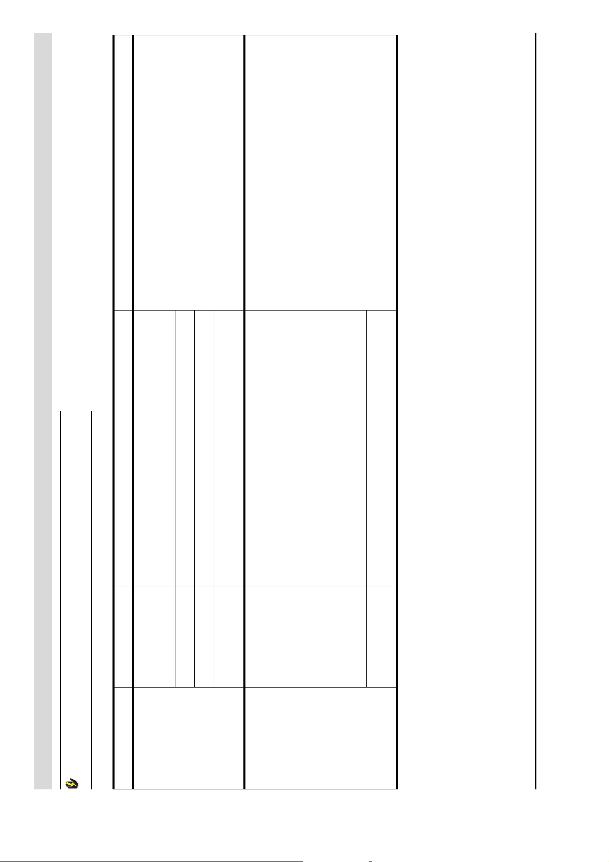
Table 8 . 1 General errors Page 2 of 2
Explosive ignition
Symptom Cause Solution Remarks
Poor flame profile
• Anodes not making
red
Power Anode
(optional)
• Indicator lamp is
• Break in one of the
• Anode poorly
No power supply to the
• Indicator lamp is
potentiostat;
off
Release R.2.0 Uk 51
Page 52
is
If ignition is not rectified, consult your installer
installer.
- Check whether the control thermostat is working.
- Check whether the high-limit thermostat is working.
- Check that the circulation pump (if present) is working.
- Check whether the thermostat may be broken.
- Check whether the thermostat sensor may be broken.
2. Check the voltage across the isolator.
The measured voltage must be 230V AC +15% -10%.
2. Check that gas control opens (clicking of the gas control).
3. Check the gas control wiring.
1. The safety thermostat has cut out correctly:
2. The safety thermostat has cut out without apparent reason:
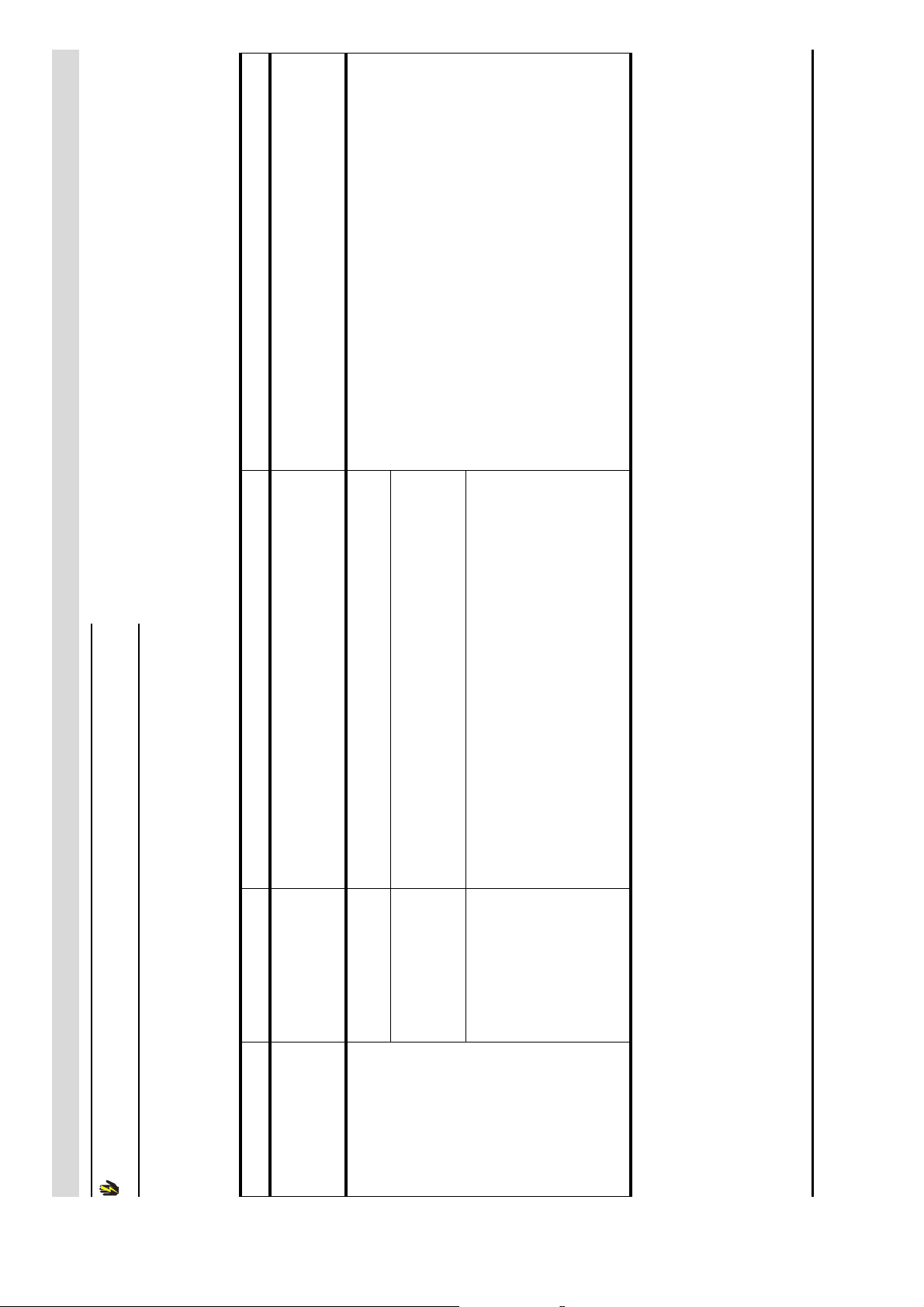
If the water heater fails to supply any hot water, there are several possible causes.
Consult the table Table 8.2 No hot water.
Warning
Maintenance should only be carried out by a qualified service and maintenance engineer.
8.3 Troubleshooting table 'no hot water'
Table 8.2 No hot water
No power 1. Check that the isolator is ON.
flame LIT)
No ignition (Pilot
Symptom Cause Solution Remarks
Pilot flame OUT Pilot flame blown out 1. Start up the water heater. See paragraph 7.2 Starting up. If the error cannot be resolved or is persistent, contact your
No Gas: 1. Check that the gas valve is open.
The safety thermostat
has cut out
Release R.2.0 Uk 52
Page 53
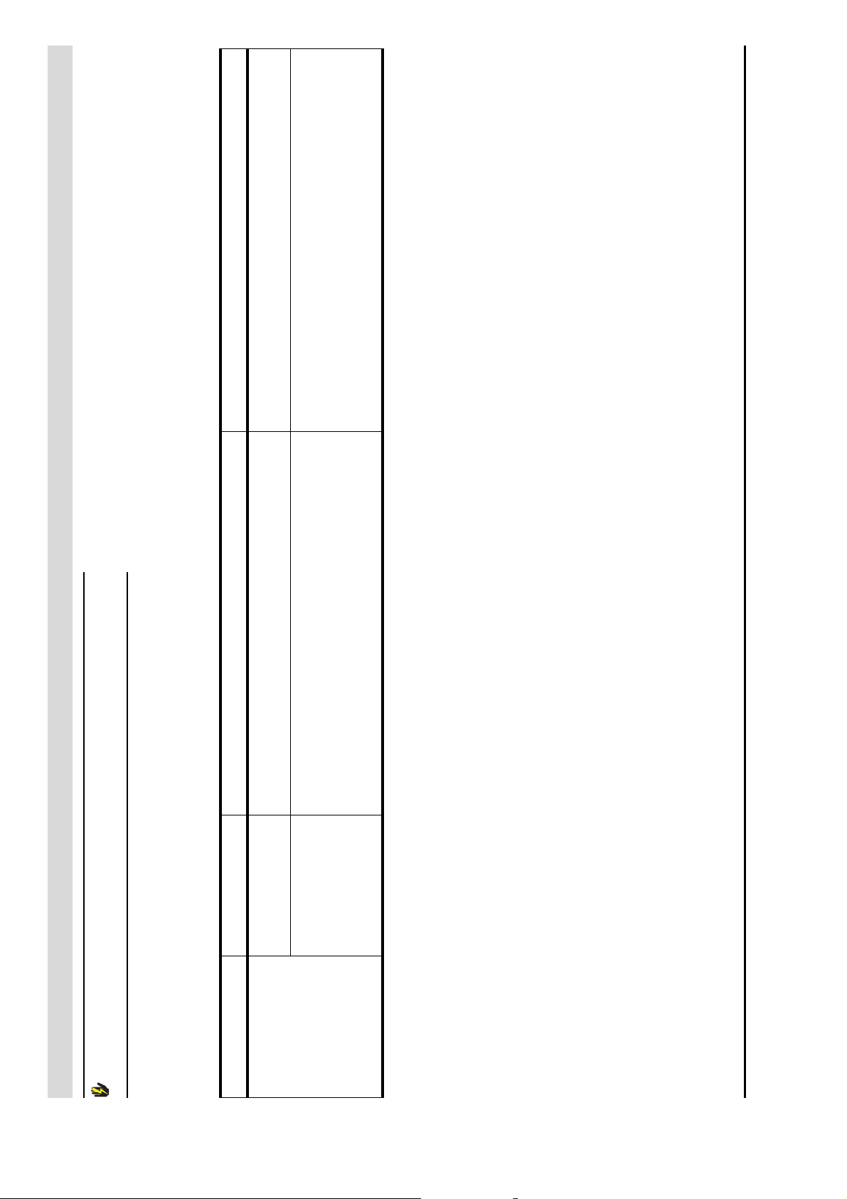
is
If the error has not been rectified and no other cause can be found,
isolate the water heater from the power supply, shut off the gas
valve and alert your installer.
heater enough time to heat up the water.
thermostat is cutting in/out. If so, check that the circulation-
and/or top to bottom recirculation pumps are working properly.
1. Reduce the rate of hot water consumption. Allow the water
Hot water supply used
up
2. If this error occurs regularly, check whether the high-limit
Release R.2.0 Uk 53
Set the control thermostat to a higher setting. See paragraph
5.5 Control thermostat.
) too low
set
If the water heater fails to supply any hot water, there are several possible causes.
Consult the table Table 8.3 Insufficient hot water
Warning
Maintenance should only be carried out by a qualified service and maintenance engineer.
8.4 Troubleshooting table 'insufficient hot water'
Table 8.3 Insufficient hot water
setting (T
Symptom Cause Solution Remarks
Insufficient hot water Water temperature
Page 54

is
Warning
Maintenance should only be carried out by a qualified service and maintenance engineer.
Release R.2.0 Uk 54
Page 55

s
s
9 Maintenance
9.1 Introduction
Introduction
cCaution
Maintenance may only by carried out by an approved service and
maintenance engineer.
At each service, the water heater undergoes maintenance both on the water
side and on the gas side. The maintenance should be carried out in the following
order.
1. Preparing for maintenance;
2. Water-side maintenance;
3. Gas-side maintenance;
4. Finalising maintenance.
9.2 Preparing for
maintenance
9.3 Water-side
maintenance
n Note
Before ordering spare parts, take a moment to write down the water heater
type and model and the full serial number of the water heater. Only with this
information can you be sure to receive the correct spare parts. These details
can be found on the rating plate.
To test whether all components are still working properly, you should complete
the following steps:
1. Check the supply pressure and burner pressure and adjust these, where
necessary. See paragraph 3.12 Checking the supply pressure and burner
pressure. Also check that this is running properly during the warm-up cycle.
See paragraph 7.4 Heating cycle.
2. Check that all components of the flue gas system are properly attached.
3. Test the operation of the expansion valve of the cold water supply
arrangement. The water should spurt out.
4. Test the overflow operation of the T&P valve. The water should spurt out.
5. Check the wastewater pipes of the overflow valves and remove any scale
deposits that may be present.
6. Drain the water heater. See paragraph 4.3 Draining the water heater.
9.3.1 Introduction
The following steps should be carried out on the water side:
1. Checking the anodes.
2. Descaling and cleaning the heater.
9.3.2 Checking the anodes
Timely replacement of the anodes extends the service life of the water heater.
The anodes that are present must be replaced as soon as they are 60% or more
used up (take this into consideration when determining the maintenance
frequency).
Instruction manual DR-LP 55
Page 56
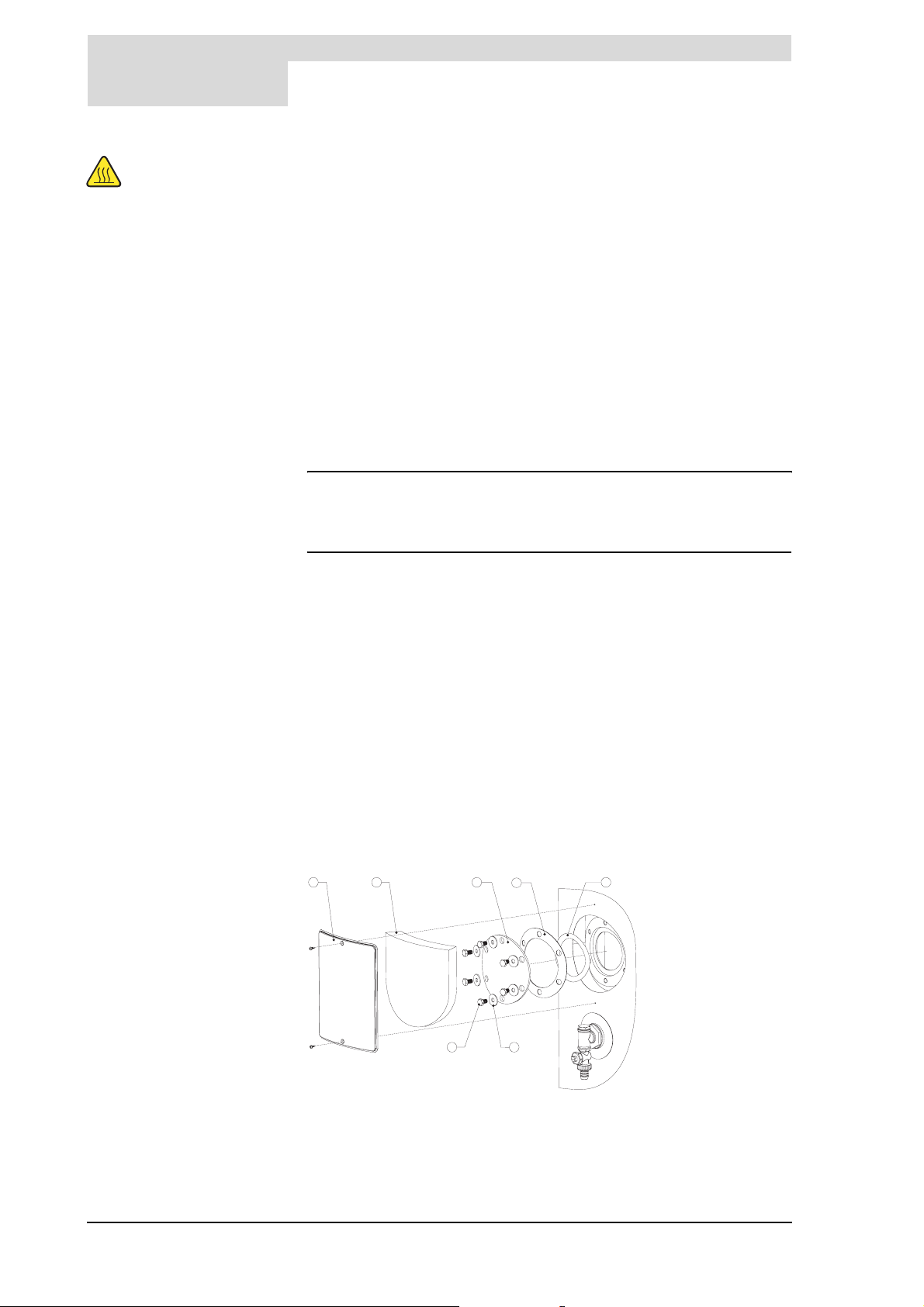
9
Maintenance
s
Take care
The draught diverter
and the cover may be
hot.
9.3.3 Descaling and cleaning the heater
1. Remove the flue gas thermostat connector from the connector on the unit.
2. Disconnect the draught diverter from the flue gas discharge.
3. Undo the screws on the draught diverter.
4. Remove the draught diverter from the water heater.
5. Undo the screws on the cover on the top of the water heater.
6. Remove the cover from the water heater.
7. Remove the sealing ring from the hot water tank.
8. Loosen the anodes using suitable tools (27 mm A/F).
9. Check the anodes and if necessary, replace them.
10. Now also check the flue baffles. Replace them, if necessary. See paragraph
9.4.4 Checking the flue baffles.
11. Fit a new sealing ring around the edge of the hot water tank and replace the
cover.
12. Reconnect the flue gas thermostat connector to the connector on the unit.
n Note
This unit is also appropriate for the use of Power Anodes. These are
available as an accessory and can be ordered separately. Please check
your Power Anode instructions for correct use or consult your installer.
Scale and lime buildup prevent effective conduction of the heat to the water.
Periodic cleaning and descaling prevents buildup of these deposits. This
increases the service life of the appliance, and also improves the heating
process.
Take the rate of scale formation into account when deciding on maintenance
frequency. Scale formation depends on the local water composition, the water
consumption and the water temperature setting. A water temperature setting of
maximum 60
To guarantee a good, watertight seal around the cleaning opening, the gasket ,
O-ring g, spring washers, bolts and if necessary, the lid c should be replaced
with new parts before reassembly. See Figure 9.1. A special set is obtainable
from State for this purpose.
To simplify descaling and cleaning of the tank, the appliance is equipped with
two cleaning openings.
O
c is recommended for prevention of excessive scale buildup.
1
Figure 9.1 Cleaning opening
1. Remove the cover plate a on the outer jacket. See Figure 9.1.
2. Carefully remove the insulation b and set it to one side. This will be needed
2
again later.
5
6
3
4
7
56 Instruction manual DR-LP
Page 57

s
Gas-side maintenance
3. Undo the bolts.
4. Remove the lid, the gasket and the O-ring.
5. Inspect the tank and remove the loose scale deposits and contamination.
6. If the scale cannot be removed by hand, then the appliance will need to be
descaled using a suitable cleaner.
7. Close the cleaning opening. To avoid damage to the tank, the bolts that
fasten the lid should be tightened with a torque no greater than 50 Nm. Use
1
5
3
suitable tools for this. To properly seal the cleaning opening, we recommend
tightening the bolts in the sequence shown in Figure 9.2.
4
2
Figure 9.2 Bolt tightening
sequence
9.4 Gas-side
maintenance
Take care
The burners may be
hot.
6
9.4.1 Introduction
On the gas side the following steps should be carried out:
1. Cleaning the burners.
2. Cleaning the injectors.
3. Checking the flue baffles.
9.4.2 Cleaning the burners
1. Detach the burners.
2. Carefully remove any contaimation present on the burners.
3. Re-attach the burners.
9.4.3 Cleaning the injectors
1. Detach the injectors.
2. Remove any contamination present in the injectors.
3. Re-attach the injectors.
9.4.4 Checking the flue baffles
Take care
The flue baffles may
be hot.
9.5 Finalising
maintenance
1. Complete steps 1 to 7 from paragraph 9.3.2 Checking the anodes.
2. Remove the flue baffles from the water heater.
3. Check the flue baffles for rust and remove any rust which is present.
4. Check the flue baffles for wear and replace any worn flue baffles.
5. Fit a new sealing ring around the edge of the hot water tank and replace the
cover.
6. Reconnect the flue gas thermostat connector to the connector on the unit.
To finalise the maintenance carry out the following steps:
1. Fill the water heater. See paragraph 4.2 Filling the water heater.
2. Re-start the water heater. See 7.2 Starting up.
Instruction manual DR-LP 57
Page 58

9
Maintenance
s
58 Instruction manual DR-LP
Page 59
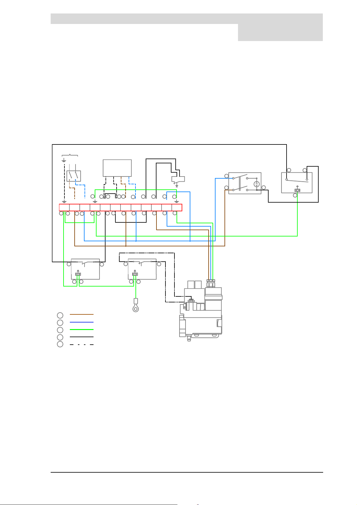
is
A DR-LP electrical
diagram
230V AC
50Hz
L
N
H
L N
3
L L N
123456789 1210 11
3
3
3
1
3
2
4J4 4
4
4
1
2
1
2
1
4
2
LL3NL
4 1
A
2
E
2
4
3
3
2
2
4
1
1
3
4
4
B
4
11
12
3
11
4
3
12
4
3
C
5
D
G
1 =
2 =
3 =
4 =
5 =
TERMINAL BLOCK CONNECTIONS:
A Earth
NNeutral
1
Phase input to week timer
L
2
Phase input to thermal non-return safety device
L
3
Phase input to main gas valve
L
brown
blue
yellow/green
black
white (flat cable)
Figure A.1 SCT electrical diagram
11
3
12
5
3
F
COMPONENTS:
A On/off switch
B Con trol thermostat
C High-limit thermostat
D Safety thermostat
E Thermal non-return safety device
F Gas control
G Eye terminal (for earthing to the Jacket)
OPTIONAL COMPONENTS:
H Main power switch
J Week timer
Instruction manual DR-LP 59
Page 60

A
DR-LP electrical diagram
is
60 Instruction manual DR-LP
 Loading...