

1
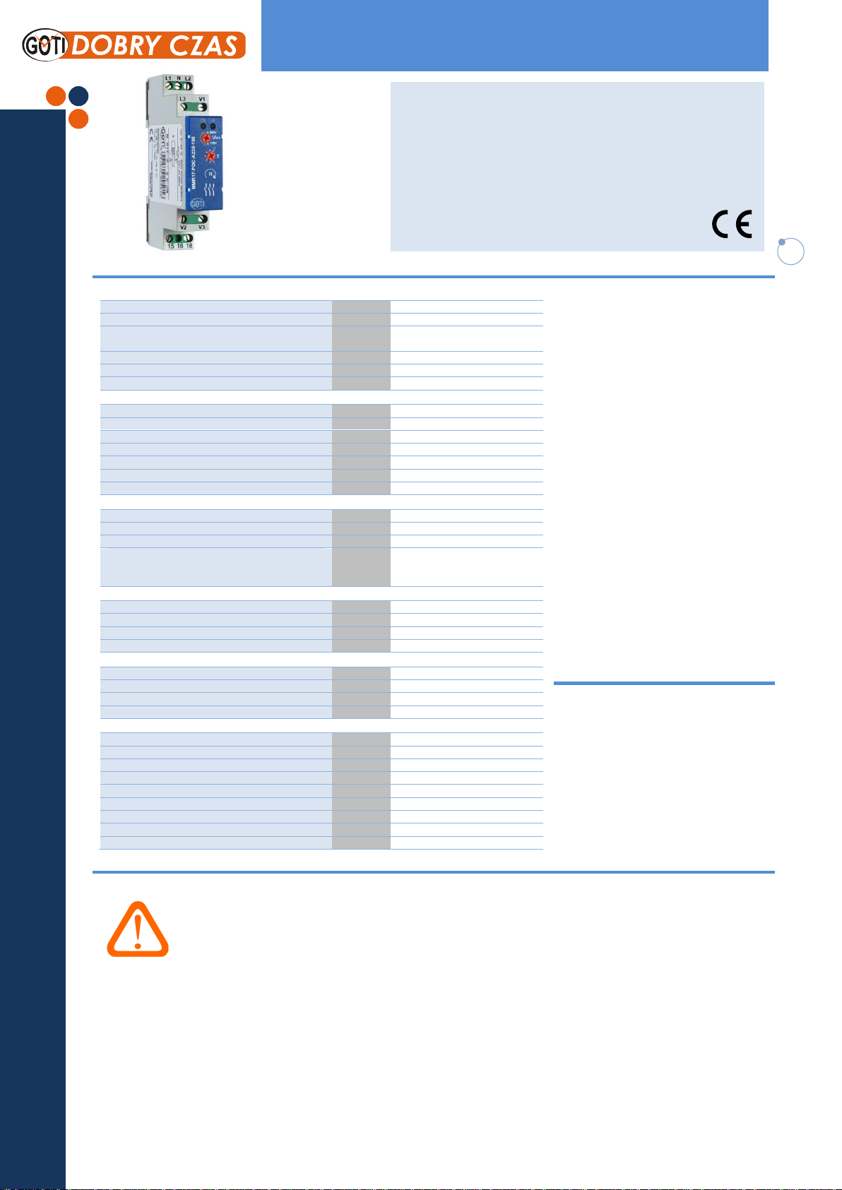
Voltage monitoring in 3-phase mains
MMR17-PDC-A230-108
Technical data
Description
Output circuit
Contact arrangement
1 CO
Rated voltage
V AC
250/400
Switching current range AC1
DC1
A/V AC
A/V DC
8/250
8/24
Switching load range AC1
VA
2 000
Contact resistance
mΩ
≤ 100
Max. rated current A 8
Input circuit
Terminals
L1, L2, L3, N, V1, V2, V3
Supply voltage Un AC (50-60Hz) = measured voltage
V
3x400/230
Tolerance 0,8…1,1Un (184…253V)
Phase power supply control system
L1
Rated consumption
VA
≤ 8
Rated frequency
Hz
47…63
Rated surge voltage
V
4 000
Insulation
Insulation rated voltage
V AC
400
Rated surge voltage
V
4 000 1,2/50s
Overvoltage category
III
Dielectric strength
Input – output
Open contact
V AC 4 000
1 000
Measuring circuit
Regulation range asymmetry U
asym
V
30…70V
Functions MA, MS
Setting accuracy % ≤ 5
Repeatability % ≤ 2
Time module data
Setting range of time off delay
s
1…6
Recovery time s 1,2
Reset time
ms
≤ 500
The accuracy of the timing
%
20
General data
Electrical life AC1 at 1000 VA resistive load
cycles
≥ 1,5 x 10⁵
Mechanical life
cycles
≥ 1 x 10⁷
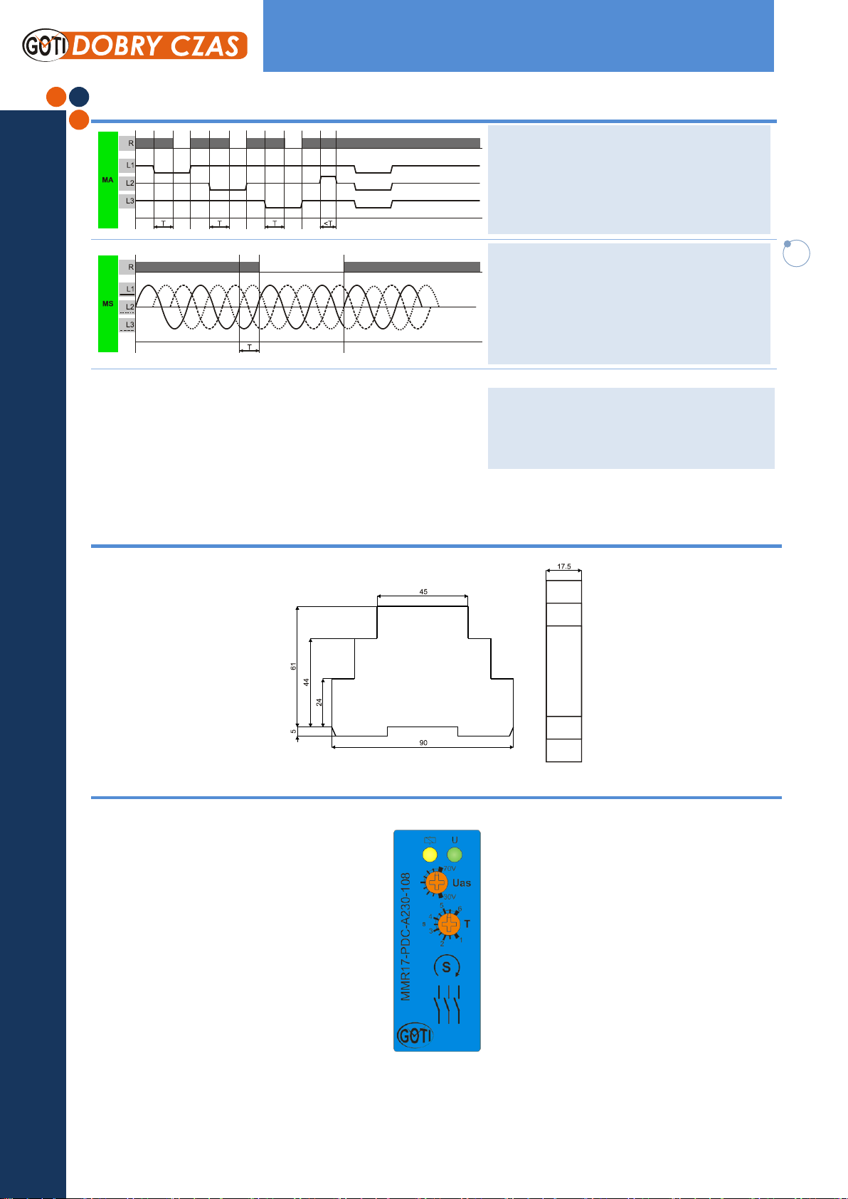
Dimensions (L x W x H) / Weight
mm / g
90 x 17,5 x 66 / 50g
Ambient temperature / storage temperature
ºC
-40…+70 / -20…+55
IP rating IP20
Relative humidity
%
85
Shock resistance
g
15
Vibration resistance
mm
0,35 10…55Hz
LED indicator 2 LED
The supervisory relay is designed for
applications in automation and control
systems to control the asymmetry, phase
sequence and activating contactor’s contacts
in AC three-phase networks.
It is used to secure loads (eg. motors) from
the voltage unbalance, incorrect phase
sequence or damage to the executive
contactor’s contacts.
The relay has an adjustable off delay time
range from 1s. to 6s. and an adjustable
voltage asymmetry threshold from 30 to 70V
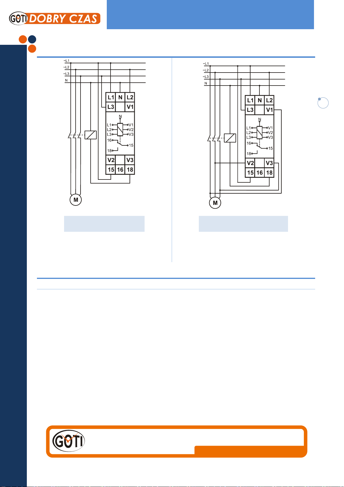
The relay is powered from L1 phase and does
not protect from symmetric voltage drop. In
case of detecting voltage asymmetry behind
the executive contactor (at the V1, V2, V3
terminals) the relay will go off and
disconnection and reconnection is required
for restarting.
After the powering is given system will switch
the contactor’s circuit only in the absence of
asymmetry and when the correct phase
sequence is detected, regardless of the
present, set time delay.
If you don’t need to control contactor’s
contacts, the V1, V2 and V3 inputs can be left
and remain unconnected.
Relay status is indicated by two LEDs.
Mounting
Mounted on DIN-rail TS 35 according to EN
60715
Mounting position: any
IP rating IP20
Tightening torque: max. 1 Nm
Terminal capacity: 1 x 0.5 to 2.5 mm²
with/without multicore cable end 1 x 4 mm2
without multicore cable end 2 x 0.5 to 1.5
mm² with/without multicore cable end 2 x
2.5 mm2 flexible without multicore cable
end
Danger!
Ordering information
Read and understand these instructions before installing, operating or maintaining
the equipment.
Never carry out work on live parts! Danger of fatal injury! The product must not be
used in case of obvious damage. To be installed by an authorized person.
MMR17-PDC-A230-108
Monitoring relays – MMR17 series
Monitoring of phase sequence and phase failure
Monitoring of asymmetry
Regulation of asymmetry and the time delay
Connection of neutral wire optional
Supply voltage = measuring voltage
1 change over contact
Width 17.5mm
Installation design
MMR17-3126 v1.0
2
Voltage monitoring in 3-phase mains
MMR17-PDC-A230-108
Functions
Inspection contactor contacts
Dimensions
Front panel view
When it detects a voltage asymmetry for the contactor,
the relay will be turned off permanently, and restart it
requires disconnecting and reconnecting the power
supply. This lock has been introduced to prevent the
cyclic ON and OFF contactor.
Function - MS (sequence) – Phase sequence monitoring
When all the phases are connected in the correct
sequence and the measured asymmetry is less than the
set value, the output relay switches into on-position
(yellow LED illuminated). When the phase sequence
changes, the output relay switches into off‑position
(yellow LED not illuminated).
Functions - MA (asymmetry) – Asymmetry monitoring
As soon as the asymmetry exceeds the value at the Uas regulator, the set interval of the tripping delay (DELAY)
begins. After the interval has expired the output relay R
switches into off-position (yellow LED not illuminated).
MMR17-3126 v1.0
3
Dobry Czas Sp. z o.o. 51-315 Wrocław ul. Miłostowska 7/6 ; Poland
+48 71 729 95 90
marketing@dobry-czas.pl
www.dobry-czas.pl
Voltage monitoring in 3-phase mains
MMR17-PDC-A230-108
Connections diagrams
LED indicator
Yellow LED
indication of relay R output.
Green LED
indication of supply voltage.
With the control contacts of the contactor
Out of control contactor contacts
MMR17-3126 v1.0
 Loading...