

Page 1
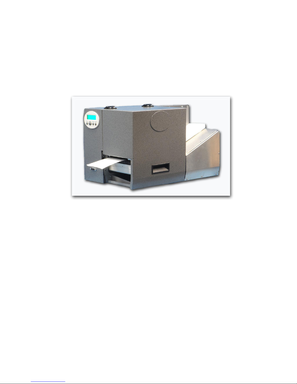
ThermaPrint 64 User’s Manual
from
DoraniX
Page 2

Thermaprint 64 User Manual
Table of Contents
Quick Start Menu ................................................................................................................ 4
Printer .............................................................................................................................. 5
Printer Interface .............................................................................................................. 5
Power Stacker ................................................................................................................. 6
Single-Start Catch Tray................................................................................................... 7
Ramp Positioning ............................................................................................................ 7
Separator ......................................................................................................................... 8
Software Settings ............................................................................................................ 8
X-adjust print location .................................................................................................... 9
Introduction ....................................................................................................................... 10
Setup ................................................................................................................................. 10
Operation........................................................................................................................... 12
Troubleshooting ................................................................................................................ 13
Maintenance ...................................................................................................................... 16
Interval and Cleaning products ..................................................................................... 16
Changing the separator roller ........................................................................................ 16
Cleaning the print head ................................................................................................. 16
Changing the print head ................................................................................................ 17
Cleaning the belts and rollers ........................................................................................ 18
Cleaning the Gap Sensor ............................................................................................... 18
Appendix A: Menu System and System Preferences ....................................................... 19
PRINT INFO ................................................................................................................. 19
Printer Status ................................................................................................................. 19
Memory status ........................................................................................................... 19
Font status ................................................................................................................. 20
Service Status ............................................................................................................ 21
Dottest endless .......................................................................................................... 22
Dottest punched ........................................................................................................ 22
Reference label.......................................................................................................... 22
PRINT PARAMETERS................................................................................................ 23
Print speed ................................................................................................................. 23
Feed speed ................................................................................................................. 23
Material type ............................................................................................................. 24
Material length .......................................................................................................... 24
Material width ........................................................................................................... 24
Print direction............................................................................................................ 24
Punch offset .............................................................................................................. 25
Bar code multip. ........................................................................................................ 25
UPC plain-copy ......................................................................................................... 25
EAN Read line .......................................................................................................... 25
EAN sep. lines .......................................................................................................... 26
Rotated Barcodes ...................................................................................................... 26
X-print adjust ............................................................................................................ 26
Y–print adjust............................................................................................................ 26
Punch mode ............................................................................................................... 27
Punch level ................................................................................................................ 27
2
Page 3

Thermaprint 64 User Manual
INTERF. PARAM. ....................................................................................................... 28
SYSTEM PARAMETERS ........................................................................................... 28
Foil end warning ....................................................................................................... 28
Foil warn stop ........................................................................................................... 28
Autom. dot check ...................................................................................................... 28
Early dottest .............................................................................................................. 29
Latest dottest ............................................................................................................. 29
Dottestarea from........................................................................................................ 29
Dottestarea to ............................................................................................................ 30
Print Interpret. ........................................................................................................... 30
Character sets ............................................................................................................ 30
Character filter .......................................................................................................... 30
Light sens. type ......................................................................................................... 30
Head-sensor dist. ....................................................................................................... 30
Sens. punch-LS ......................................................................................................... 30
Ribbon autoecon. ...................................................................................................... 31
Ribbon economy limit............................................................................................... 31
Turn-on mode............................................................................................................ 31
Interface delay ........................................................................................................... 31
Error reprint .............................................................................................................. 31
Single job mode ........................................................................................................ 32
Head resistance ......................................................................................................... 32
Temp. reduction ........................................................................................................ 32
Voltage offset ............................................................................................................ 33
Miss. label tol. ........................................................................................................... 33
Gap detect mode ....................................................................................................... 33
Mat. end detect. ......................................................................................................... 33
Periph. device ............................................................................................................ 34
Singlestartquant......................................................................................................... 34
External signal .......................................................................................................... 34
Start mode ................................................................................................................. 34
Start source................................................................................................................ 35
Signal edge ................................................................................................................ 35
Signal / buzzer........................................................................................................... 35
Special Function............................................................................................................ 35
Delete job .................................................................................................................. 35
Delete spooler ........................................................................................................... 35
Factory settings ......................................................................................................... 35
Service Function ........................................................................................................... 36
Heat Settings ................................................................................................................. 36
Appendix B: External Attachments .................................................................................. 37
Power Stacker ............................................................................................................... 37
Single-Start Catch Tray................................................................................................. 37
Appendix C: Parts Callout ................................................................................................ 39
Appendix D: Replacement Parts List ................................................................................ 41
Appendix E: Universal Interface Board (Optional) .......................................................... 43
3
Page 4

Thermaprint 64 User Manual
Quick Start
Menu
4
Page 5

Thermaprint 64 User Manual
Printer
1. Remove printer from box and place all shipping materials in a location where they
can be used later should the printer need to be shipped back for repair.
2. Follow the setup instructions in the following pages for any options your printer
may have.
3. Plug the printer in using the supplied power cord and turn it on.
4. Install the ribbon as shown in Figure 1 on page 6 and by the video provided on
www.doranix.com.
5. Place a stack of product in the feeder. Place them in such a way so that they are
shingled and the bottom piece of product will always be the first to enter the
machine.
6. Feed a few samples through and make sure that the printer feeds as desired
(should feed consistently with a gap between the samples).
7. Start Printing!
Printer Interface
1. Download the driver to be used with the desired interface from
www.doranix.com.
2. If printing with USB or Serial simply plug in the interface cord, select the correct
driver and print.
3. If printing over the network with an Ethernet cable, select the correct driver and
set the desired IP on the printer by following these steps:
1. Enter the menu by putting the printer offline and pressing Prog-Esc
2. Press Cut to get to Interface Para
3. Go down to Network Param.
4. Go to IP address and make sure it is set correctly. If not, change it to the
correct value and restart the printer.
5
Page 6

Thermaprint 64 User Manual
Power Stacker
Parts
6 red screws (4 large, 2 small)
1 sheet metal shield
1 stacker housing
2 stacker rods
2 4mm screws
1 stacker tray
Magnetic guide(s) (standard: could change if custom design needed)
Assembly
1. Attach sheet metal shield onto the front of the bosch frame using the 2 small red
screws provided.
2. Screw stacker rods onto the stacker housing.
3. Lubricate O-Ring grommets on the stacker tray using Windex.
4. Slide the stacker tray onto the stacker rods and screw in the 2 4mm screws into
the ends of the stacker rods.
5. Position the magnetic guide(s) in such a way to allow for product to stack as
desired.
6. Plug the DB-15 cable from the stacker into the front port on the printer.
7. Secure the screws in the DB-15 connector to the printer.
8. CAUTION! - Make sure printer is off when plugging the stacker in,
otherwise circuitry could be damaged!
9. Attach stacker to the bosch housing by inserting 2 of the provided large red
screws through the holes on the inside of the housing. Tighten to secure stacker to
printer.
6
Page 7
Thermaprint 64 User Manual
Single-Start Catch Tray
Parts
2 red-capped screws
1 single-start catch tray
Assembly
Attach the tray to the front of the printer using the 2 red screws.
Options
Turn Single-Start Function On/OFF
Go into the menu and go to System Parameters > Periph. Device > Single
Start (to enable function) or none (to disable function) and then press
Online to select.
Change the number of products printed at a single time
Go into the menu and go to System Parameters > Singlestartquant and
then select the number of products desired to print at a time (default is 1).
Press Online to apply the desired number.
Ramp Positioning
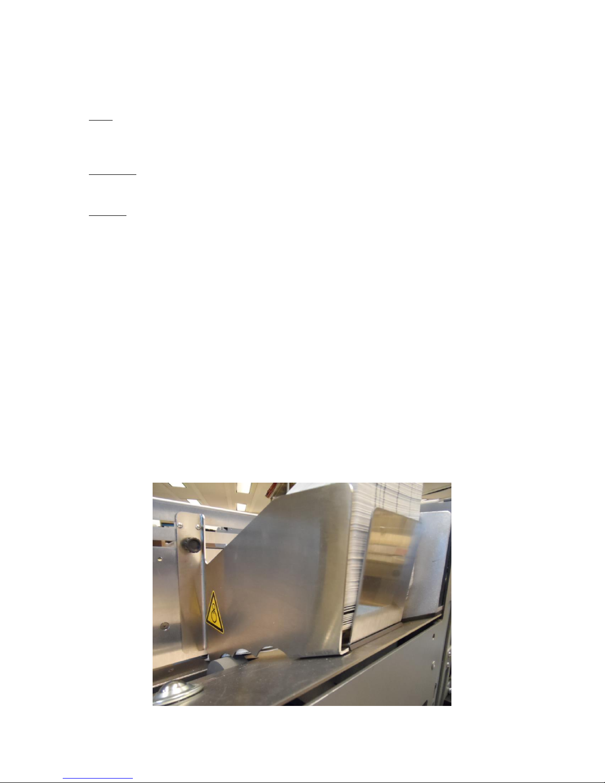
The printer might have a ramp supplied to aid in the feeding process. The position in
which the ramp needs to be placed to help feeding can be a small window. If placing too
far under the stack of product in the feeder, the ramp will lift the product off of the
agitator wheel which will likely result in the product not wanting to feed. If the ramp is
too far back, not enough pressure is placed on the backs of the cards to help push them
into the printer. Please refer to Figure 1 for the location the ramp will likely need to be
placed in relation to the cards.
7
Figure 1: Correct ramp location
Page 8

Thermaprint 64 User Manual
If the ramp does not seem to help the feeding process as it should after placed as shown,
move it slightly either forward or back as necessary until it reaches the desired feeding
performance. If supplied with a 1” wide ramp, it will likely need to be placed between the
agitator wheel and the wall of the printer.
Separator
The separator is a fixed wheel used to limit one piece of product entering the printer at a
time. This should be set correctly when you receive the machine. It is possible that
product thicknesses change or that the separator could get adjusted by accident. If this
happens the separator will need to be either raised or lowered. To raise the separator turn
the silver separator knob clockwise. To lower the separator, turn the knob
counterclockwise. If the product is double feeding (more than one coming through at a
time) the separator wheel needs to be lowered to restrict a second one from coming
through. If the product will not feed the separator may need to be either raised or
lowered. Try lowering it first. It is possible the product needs the pressure from a surface
above in order to be fed into the printer. If nothing changes after lowering it, try raising it
gradually. Adjusting the separator can make big differences in feeding very quickly so
small adjustments needs to be made to ensure feeding well. The knob should only be
turned 1/32-1/16 of a full rotation at a time. Larger movements could cause feeding to go
from no product entering the machine to double feeding in a single movement.
The separator comes in two materials: blue urethane and grey, low-density, urethane.
Generally, the blue separator is used for most products: Tyvek pouches, cardstock,
medical paper, other paper stock, plastic placards, envelopes, plastic pouches, and foil
pouches. The grey separator is used for Tyvek lids. The separator will need to be
changed depending on material type being printed. This is accomplished with the
procedure in the Maintainence Section.
Software Settings
No matter what software you are using to send a job to the printer, there are several
settings that need to be set correctly to ensure proper printing.
Printhead temperature: This setting is located inside of the driver and can be
found in the print dialogue box usually under document properties, settings, or
something else similar depending on the software being used. It is usually labeled
as print contrast or darkness although sometimes it is called temperature. The
temperature that should be used depends on the ribbon being used and the
material type being printed on. For a list of the most common optimal
temperatures for our most popular ribbons, please see “Heat Settings” in
Appendix A.
Print Speed: Different print speeds can affect the quality as well as the durability
of the printing. The print speed is set inside of the driver and can be found in the
print dialogue box usually under document properties, settings, or something else
similar depending on the software being used. It should be labeled as “Speed” or
something similar depending on the software being used. The default speed used
8
Page 9

Thermaprint 64 User Manual
for most printing is 6ips. If you feel as if this speed is not what it should be, please
contact DoraniX technical support at 303-271-0986.
Label Length: It is very important that the length of the product is set correctly in
the software. If you believe this may be wrong check with the person who created
the image. An incorrect material length could result in every other piece of
product being printed on or even only the first being printed on.
X-adjust print location
There are several ways to adjust the x-location of the image being printed. They are as
follows:
Move the image in the software - This is an a quick and simple fix to the x-
location of the image being off, however it is not always feasible if there are a
high number of image files being used.
Move the printhead – By loosening the thumbscrews on the printhead and sliding
it back and forth over the product the x-location of the image moves with it. Be
sure to tighten the thumbscrews before attempting to print.
X-print adjust setting – In the menu under Print Parameters is the setting X-print
adjust. The settings specs are as follows: x inch/s Setting range: -5.0 to +5.0 mm;
Unit interval: 0.1mm Default: 0.0 mm
• Maximum offset away from the edge of the label: +5.0 mm
• No offset: 0.0mm
• Maximum offset towards the edge of the label: -5.0 mm
9
Page 10
Thermaprint 64 User Manual
Introduction
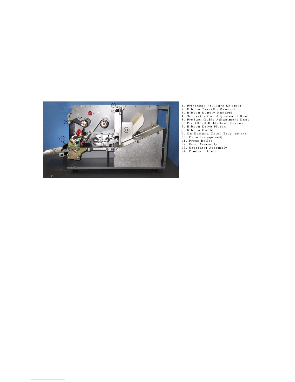
This user manual will introduce you to the Thermaprint 64, describe how to setup,
operate, troubleshoot problems, and maintain the print head, sensors, and belts of the
Thermaprint 64. Also included in Appendix A is a full description of the menu system
with detailed descriptions of the parameters, options, and functions accessible through it.
Below, in Figure 1, is a picture of the Thermaprint 64 with the cover opened, and
provides a detailed call out of the various components and modules. The terms provided
in Figure 1 will be used throughout the rest of this manual for consistency.
Figure 1: Thermaprint 64 Part description
Setup
Unpack the printer, setting aside and saving the shipping box and packing material. Plug
the printer into a standard 120V 50-60 Hz wall outlet using the provided printer power
cord. Connect the printer to a computer using the provided cable.
To download and install the Thermaprint 64 driver go to:
http://www.monarch.averydennison.com/emea/support/printer-drivers.asp
and download the zip file that contains Avery's standard installer for all of their drivers.
You will need to unzip it and run the installer executable on the computer that will
manage the printer. Click next and agree to the license agreement. The printer driver you
will need to install is the Avery Dennison 64-xx, where xx is the size of the print head in
inches (4, 5, 6 or 8). On the next page select the port that the printer is attached to, be it
USB001 for USB, or LPT1 for the Centronics, or COM1 for rs-232. For an Ethernet
connection a few additional steps are required, so if that is the desired method of
communication, for now select one of the other options and further instructions will be
include in an addendum. After you have selected the desired port, and optionally changed
the name of the printer driver to whatever you like, click Finish. The driver should be
ready to use.
Attach any other optional accessories, following the instructions in the provided
addendums. Open the cover and place a roll of near-edge wax/resin thermal transfer
10
Page 11

Thermaprint 64 User Manual
ribbon onto the ribbon supply mandrel so that the ribbon will unwind with the coated side
facing down. Place an empty ribbon core on the ribbon take-up mandrel. For coated side
in ribbons, the ribbon roll will unwind in a counter-clockwise direction and the ribbon
will come off the top side of the roll. For coated side out ribbons, these directions will be
opposite.
Peel the leader from the roll of ribbon, draw it underneath the ribbon guide and print
head, and then up and over the ribbon drive platen. Ensure that the supply and take-up
cores are aligned on their respective mandrels. Use the adhesive on the ribbon leader to
apply itself to the empty core on the ribbon take-up mandrel. While doing this process,
remove any wrinkles from the ribbon. After adhering the ribbon leader to the empty core,
you can hand rotate the take-up mandrel to advance the ribbon and remove any persistent
wrinkles. Moving the ribbon back and forth gently along the length of the ribbon guide,
print head, or ribbon drive platen will help remove any major wrinkles.
Turn the printer on using the power switch on the back of the machine. Adjust the outside
guide to the desired product width. Rotate the separator gap control knob clockwise as
viewed from the top to loosen the gap until there is an easily visible gap shown. Place a
single product into the magazine and ensure the front edge is between the gray separator
wheel and the white product drive wheel. Press the online button, to take the machine
into offline mode and then press the feed button. At this point, the separator gap should
be too wide to effectively feed the product through the machine, so decrease the separator
gap by rotating the separator gap control knob counter-clockwise to reduce the gap
between the two wheels. If the machine times out looking for the product to feed, simply
acknowledge the error by pressing the online button and then the feed button to have the
product drive wheel turn. Gently hold the back end of the product between two fingers,
and keep tightening the gap while the product drive wheel turns until the separator pulls
the product out from your fingers.
Fill the magazine the rest of the way with identical product, making sure that the bottom
of the stack is pushed forward. Next, manually adjust the material length setting to the
length provided by the labeling software under the print parameter sub-menu. When this
is done, press feed a few times to ensure that the products are feeding through
appropriately with no double feeds or jams. This paragraph should be done every time the
printer is powered on or the length of the product is changed.
NOTE: Every time the machine is powered on or the product length is changed, the
printer will need to have product fed through it until it senses a gap between two
products. This is the case even if the product length changes from 155.5 mm to 155.6
mm. To avoid this after setting up the machine, ensure that the number you enter into the
print parameter submenu option of “materiallength” is identical to the material length that
the computer sends to the printer. Also, every time you change the material length or
power on the machine, take the machine into offline mode and press the feed button once.
The machine will feed through two products, the first to find a gap between two products
and the second because a feed command has been received. If you do not do this, the first
time the printer prints, it will feed through one pouch without printing, and then print on
the second pouch.
11
Page 12
Thermaprint 64 User Manual
Next, on the connected computer download and install the correct driver. The driver
should be setup according to the communications addendum. When finished, return the
printer to online mode, and have the computer send print tasks using label design
software.
Operation
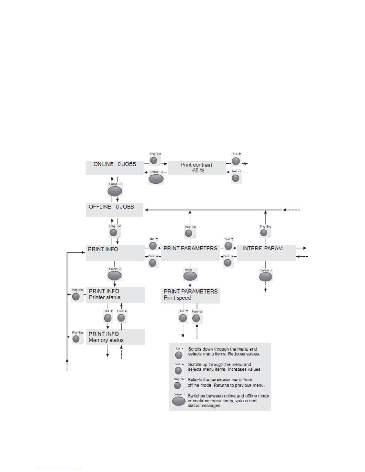
Below is a graphical explanation of how to access, navigate, and exit the menu system
within the Thermaprint 64. A full list of all the available sub menus (Print Info, Print
Parameters, etc.) and functions (Printer Status, Print Speed, etc.) within each sub menu is
available in Appendix A.
Figure 2: Graphical Explanation of Menu System
12
Page 13

Thermaprint 64 User Manual
Button(s)
Effect
Cut + Feed
Performs a Head Dot Test
Cut + Online
Runs the product transport backwards while
pressed
Feed + Online
Advances the product and ribbon while pressed
Feed + Prog Esc
Manually calibrates product length
Cut + Online + Feed
Restarts the printer
Here is an example of how to navigate and change the value of a function within the
Thermaprint 64’s menu structure:
The machine starts in Online mode. We want to change the material length to 180.2
mm. In order to do so, press the Online button and the screen should now say Offline
in the upper left hand corner. Press the Prog * Esc button and the machine will enter
the menu system and say Print Info. Press the Cut button and the screen will say Print
Parameters. Press the Online button and the screen will say Print Speed on the
bottom line. Press the Cut button three times or until the screen says Materiallength
on the bottom line. Press the Online button, and the screen will display the currently
selected material length. Use the Cut and/or Feed buttons to adjust the material length
to 180.2 mm, and then press the online button to confirm the selection. The screen
will then return to displaying Print Parameters on the top line and Materiallength on
the bottom line. Press the Prog * Esc button twice and the screen will display Offline
in the upper left hand corner. Press the Online button. The machine will then change
back to being in Online mode and display Online in the upper left hand corner of the
screen.
Furthermore, certain button combinations allow for varied functionality while the
machine is in the Offline mode as described below.
Table 1: Effects of Button Combinations
Troubleshooting
There are 2 types of error messages given by the Thermaprint 64, self-acknowledging
messages and error reports.
Messages beep once and display a short message detailing the message. They
acknowledge themselves after a moment, and go away on their own. Generally these
messages can be ignored as long as the printer appears to be running and printing
correctly, as they just warn you when you are close to the limits of the printer, but not
beyond them. They tend to be related to label images sent to the printer or the ribbon
running low rather than the actual mechanics of the printer itself.
Error reports cause the machine to beep repeatedly and display a short message detailing
the exact problem, which allows for easy troubleshooting (e.g. error 5003: Cover Open,
5008: Ribbon End). Error messages must be acknowledged. Pressing the cut button will
13
Page 14

Thermaprint 64 User Manual
turn the beeper off, but leave the error displayed, and pressing the enter button will
acknowledge the error and return the machine to the state it was in when the error was
interrupted. It may be necessary to press the feed button to resume printing if that is when
the error occurred. Error messages tend to relate directly to the mechanics of the printer
itself rather than the label images sent to it from a computer.
If an error message persists on start-up or during every print, turn the machine off,
disconnect the communications cable, and let it sit for 30 seconds. Then turn the machine
back on and reconnect the communications cable after the initialization sequence has
finished. If the error continues to persist, please note any messages the screen displays,
and call a service technician.
Below are some simple troubleshooting tips for common problems encountered with the
Thermaprint 64.
IF the printer will not print:
Are there any status messages or error reports that are shown on the display
screen when a print job is sent, or when the printer feeds a pouch through the
machine?
Is the ribbon properly threaded, with the coated side facing down as it passes
under the print head?
Will an info print-out work correctly? To do so, enter the menu system, enter the
PRINT INFO submenu, and then press enter on any of the print outs available. It
should print a status report. There must be product and ribbon in the machine for
it to print.
Does the printer feed pouches through completely? Ensure the separator is
correctly aligned. The Gap Adjustment (see Figure 1) knob allows for proper
separation adjustment. Clockwise rotation, as viewed from above, increases the
separator gap which makes feeding easier, but can cause double feeding to occur
if increased significantly. Counter-clockwise rotation, as viewed from above,
decreases the separator gap which makes double feeding less likely to occur, but
can cause the product to crinkle or jam if decreased significantly.
IF the print is skewed on the product:
Adjust the feed assembly so that it has a very minor skew (less than 5 degrees)
towards the back wall, so that the products are very gently pressed against the
wall, but not enough to cause them to crinkle, or corners to flip up.
Adjust the position of the red press roller along the shaft with the green lever.
Ensure the roller presses on the feed belts, otherwise it will not allow product to
pass and will cause jams.
IF the print is incorrectly positioned along the length of the pouch:
14
Page 15

Thermaprint 64 User Manual
Ensure that the sensor is set to the correct mode. To do this, enter the menu
system, enter the SYSTEM PARAMETERS submenu, and under the option Light
sens. type ensure that the correct sensor type is selected. Check the provided
recommended settings to determine the correct sensor type. Typically punched is
correct, but reflective is used for transparent product.
IF the product is consistently bent when exiting the machine
Run the printer with the cover open by disabling the interlock switch. Watch as
product goes through and try to determine what in the machine the product is
getting snagged on. The issue is generally caused by either an orange pinch roller
or the housing of the sensor that detects a gap between products. If it appears to
be a pinch roller, try readjusting the position of the pinch roller while making
sure to keep it on the blue belt. If the problem appears to be the product bending
on the orange sensor housing, try sliding the sensor back into the machine by
turning the green knob on the outside of the head assembly counter-clockwise. If
neither of these solutions seem to work, take a video depicting the issue and email
it to technical support.
IF the print quality is poor:
Adjust the print speed and/or heat value (sometimes called temperature/ darkness/
etc.) used within the labeling software. How to change this varies from software
to software, but should be under label setup, page setup, or label properties. If you
are unable to locate, please contact technical support, as they are familiar with
many of the more common label creation software. To improve quality, try to
decrease print speed and increase the heat value.
Increase the print head pressure. This is a tear-shaped orange knob above the
ribbon take-up spool (the print head pressure selector). Clockwise decreases
pressure and counter-clockwise increases pressure. This may cause wrinkling of
the product if too much pressure is applied.
IF the printer will not feed product or double feeds product:
Ensure that the separator gap is appropriately adjusted. Clockwise rotation, as
viewed from above, increases the separator gap which makes feeding easier, but
can cause double feeding to occur if increased significantly. Counter-clockwise
rotation, as viewed from above, decreases the separator gap which makes double
feeding less likely to occur, but can cause the product to crinkle or jam if
decreased significantly.
Contact technical support. Make a note of any error messages that appear on the
display screen.
15
Page 16

Thermaprint 64 User Manual
Maintenance
Interval and Cleaning products
Regular servicing and cleaning work is necessary for safe operation and high running
performance. The servicing intervals are dependent on the operation and ambient
conditions, daily operating times, and the print medium. Regularly clean the print head
and feed roller by removing any paper, adhesive, and ribbon residues using a dust-free
cloth and a neutral cleaning solution. Do not use any cleaning agents which could
damage or destroy the coating surfaces, labeling, display, type plates, electrical
components, etc. Avoid acidic or alkaline solutions. Ethanol and isopropyl alcohol (not
rubbing alcohol) are recommended for non-rubber parts. The rubber rollers and platens
are easily cleaned and rejuvenated using acetone. All rubber parts should be cleaned
when feeding operation becomes diminished.
Changing the separator roller
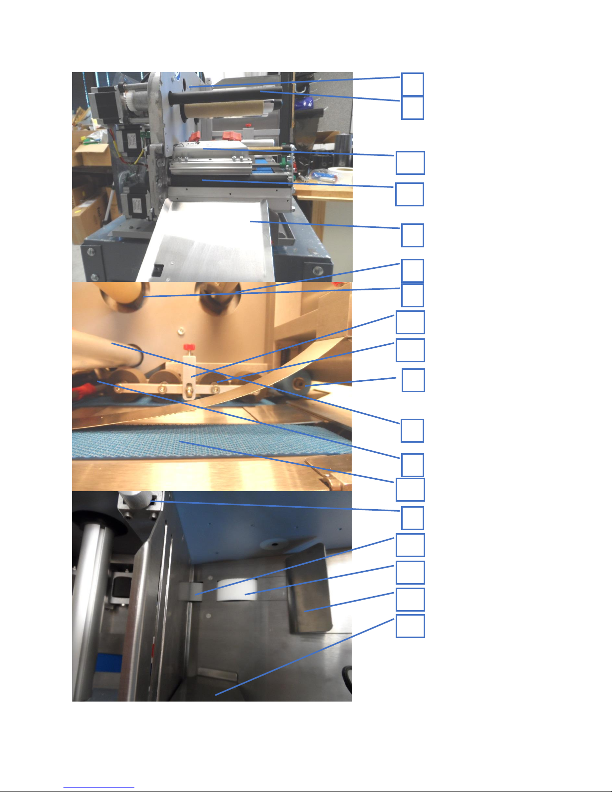
The separator (#9 Appendix C) is designed to be removable and replaceable when worn.
Also, this part might need to be changed when printing different materials ie. Tyvek
pouches vs. Tyvek lids. First, set the separator gap wide enough such that the separator is
not touching the feed wheel. Then, use a 3mm hex wrench to remove the separator screw.
Pull the old separator off and slide the new part on. Secure with the screw.
Cleaning the print head
1. Switch off the device.
2. Pull out the mains plug.
3. Remove material and ribbon.
4. Unscrew the two thumb screws on the print head module until the entire print head
module can be rotated clockwise on the contact shaft.
CAUTION! - The print head is a sensitive electronic component and can be easily
damaged by electrostatic charges. Therefore, discharge any bodily static electricity
before coming into contact with the print head by touching the base plate of the
printer. The print head does not need to be removed. Mark the position of the print
head on the contact shaft if it is not against the inside wall or outside stop.
5. Clean the print head using a dust-free cloth and a neutral cleaning solution.
CAUTION! Do not use any objects with sharp edges. Metal objects may never be
allowed to come into contact with the print head surface. They can damage the
individual elements of the print head, causing an un-repairable dead zone to form.
16
Page 17
Thermaprint 64 User Manual
6. After cleaning, return the print head module to its original position and re-tighten
the thumb screws.
7. Press the thumb screw on the tapered edge of the square shaft and ensure the exact
positioning of the print head module on the contact shaft. Also pay attention to the
position of the print head in relation to the edge of the label.
8. Before switching on the device, check whether the print head cable is still properly
connected. If this is not the case, plug in the cable correctly.
Changing the print head
The print head is adjusted to the print head module during manufacture. As a result the
print head can only be replaced in conjunction with the print head module. Before
starting, make a note of the resistance value of the new print head (denoted on the back of
the print head). It is the 4 digit number following the letter R. When placing the print
head on the print head module, ensure that the print head is lying flat.
1. Switch off the device.
2. Pull out the main power plug.
3. Remove material and ribbon.
Wait at least 3 minutes after switching off the device before removing the print
head cable from the print head. Mark the position of the print head on the contact
shaft if it is not against the inside wall or outside stop.
4. Unscrew the two thumb screws on the print head module until the entire print head
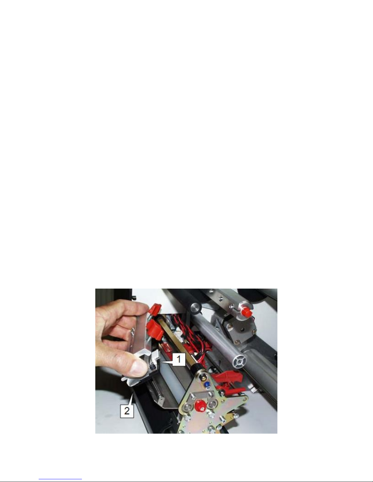
module can be removed from the contact shaft (Fig. 2).
17
Page 18

Thermaprint 64 User Manual
Fig. 8: Take care not to touch the connector contacts (1) or the thermal edge (2) when
removing the print head.
CAUTION! - The print head is a sensitive electronic component and can be
damaged by electrostatic charges. Therefore, discharge any bodily static electricity
before coming into contact with the print head by touching the base plate of the
printer. The print head may not be touched on the print bar or on the plug-in contacts.
5. To install, move the new print head module to the original position and tighten the
thumb screws.
6. Press the thumb screw on the tapered edge of the square shaft and ensure the exact
positioning of the print head module on the shaft. Also, note the position of the print
head in relation to the edge of the label.
7. Plug the print head cable back into the print head.
8. The resistance value of the print head must be entered using the parameter
"SYSTEM PARAMETERS/ Head resistance" menu option after putting the printer
into operation.
CAUTION! - Entering an incorrect value can damage the print head or affect print
quality.
Cleaning the belts and rollers
1. Switch off the device.
2. Pull out the main power plug.
3. Remove material and ribbon.
4. Remove the print head after waiting at least 3 minutes.
For detailed information refer to chapter "Changing the print head" on Page 7.
5. Turn the print roller slowly while cleaning it using a dust free cloth and neutral
cleaning solution until the entire roller is free of residue. Repeat the process for the
feed belts and separator wheels.
6. Replace the print head, referring to above for specific instructions.
7. Before switching on the device, check whether the print head cable is still properly
connected. If this is not the case, plug in the cable correctly.
Cleaning the Gap Sensor
1. Switch off the device.
2. Pull out the main power plug.
3. Remove material and ribbon.
18
Page 19

Thermaprint 64 User Manual
4. Unscrew the two thumb screws on the print head module until the entire print head
module can be rotated clockwise on the contact shaft.
The print head does not need to be removed. Mark the position of the print head on
the contact shaft if it is not against the inside wall or outside stop.
The gap sensor can now be easily accessed from above.
5. Clean the gap sensor with compressed air
6. After cleaning, return the print head module to its original position and retighten
the thumb screws. See "Cleaning the print head" on page 6 for specific directions.
7. Before switching on the device, check whether the print head cable is still properly
connected. If this is not the case, plug in the cable correctly.
19
Page 20

Appendix A: Menu System and System Preferences
In this appendix, submenus will have their names bolded and fully capitalized. The
functions within each submenu will be underlined, with the description and any
selections indented to allow for quick visual access. Changing the values and settings for
many of these parameters can severely and negatively affect print quality and speed,
while also possibly affecting product detection and transportation. Please consult with a
service technician before doing any significant changes if you are unfamiliar with the
system.
PRINT INFO
Printing of individual reports can be deactivated for certain options (e. g. for the in feed
option). A material width of 100mm is necessary to print the reports.
Printer Status
A protocol can be printed to get an overview of customer-specific parameter settings
(three pages, see [1]). Which parameters are listed, depends on the printer type.
Figure 1A: Sample Printer Status printout.
Memory status
A memory protocol can be printed to provide an overview of the distribution of the
available memory capacity (one page).
19
Page 21
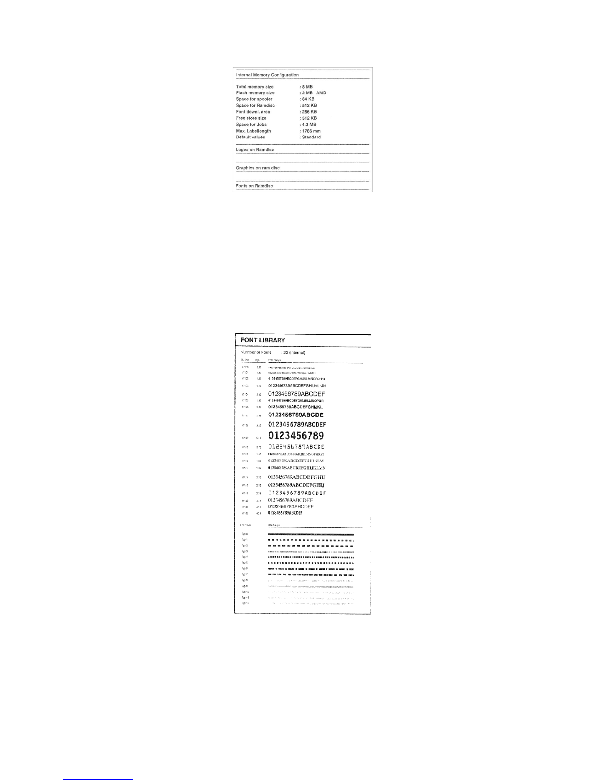
Figure 2A: Sample Memory Status printout
Font status
Print samples of all installed characters, bar codes and line samples (several pages).
The section of the printout titled Font Library shows a list of the internal fonts and
line styles and the section titled Barcode Library shows a list of the internal 1D and
2D barcode formats. These fonts and barcodes are not the only formats available, but
using them reduces label size, allowing for quicker data transfer and print speeds with
larger file types.
Figure 3A: Sample Font Library printout
20
Page 22
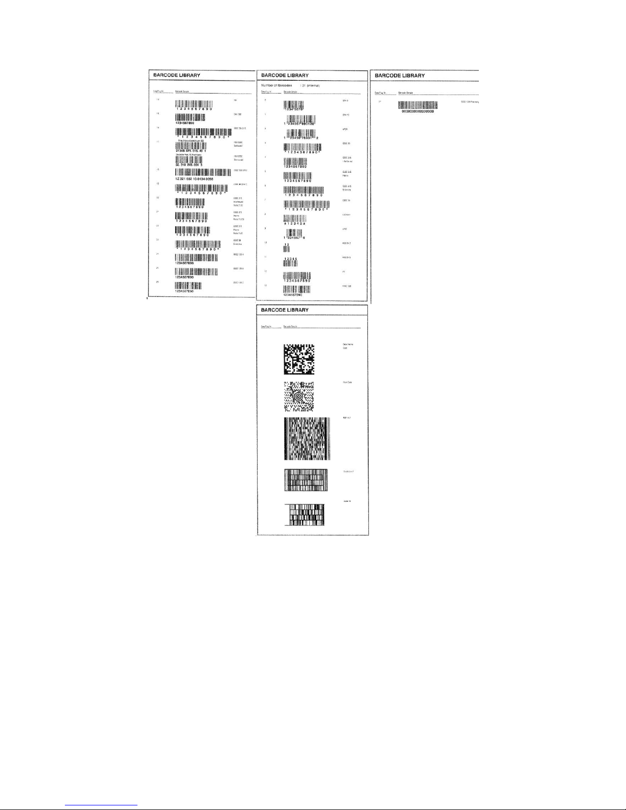
Figure 4A: Sample Barcode Library printout.
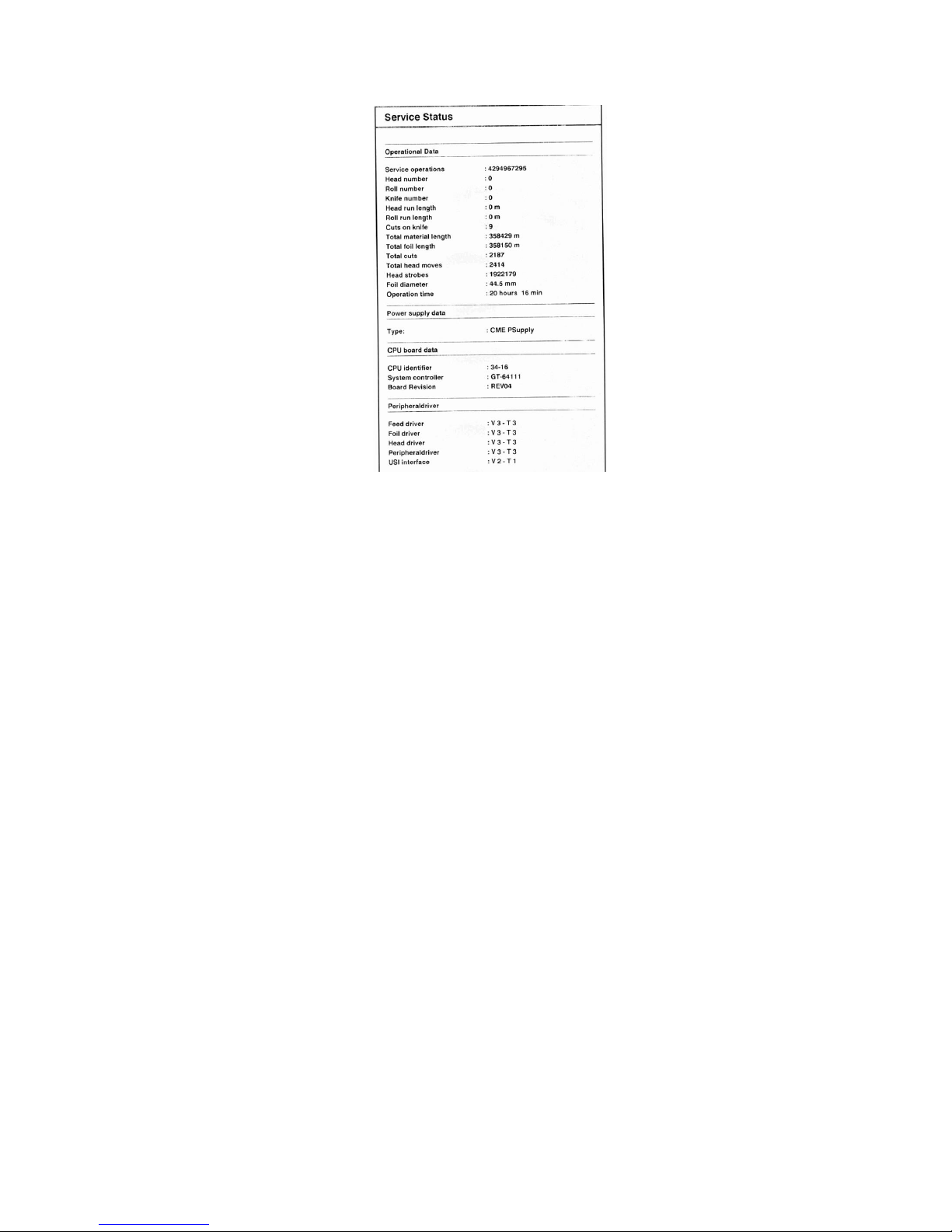
Service Status
Print the Service status report to read about operation time, no. of services, no. of
exchanged parts and other matters of service interest (one page).
21
Page 23
Dottest endless
Figure 5A: Sample Service Data printout
Not for use with Thermaprint 64. See Dottest punched.
Dottest punched
Dot test for application with punched label stock. This function prints a pattern which
enables trained personnel to check the adjustment as well as the function of the print
head. The Dottest endless or Dottest punched prints a pattern consisting of 33 rows
filled with vertical lines on the upper label area. All lines have a constant distance of
4 dots. With every new row, the line pattern is shifted one dot. The resulting linepattern repeats every four rows. The test pattern shows missing dots clearly as white
vertical lines running through the pattern.
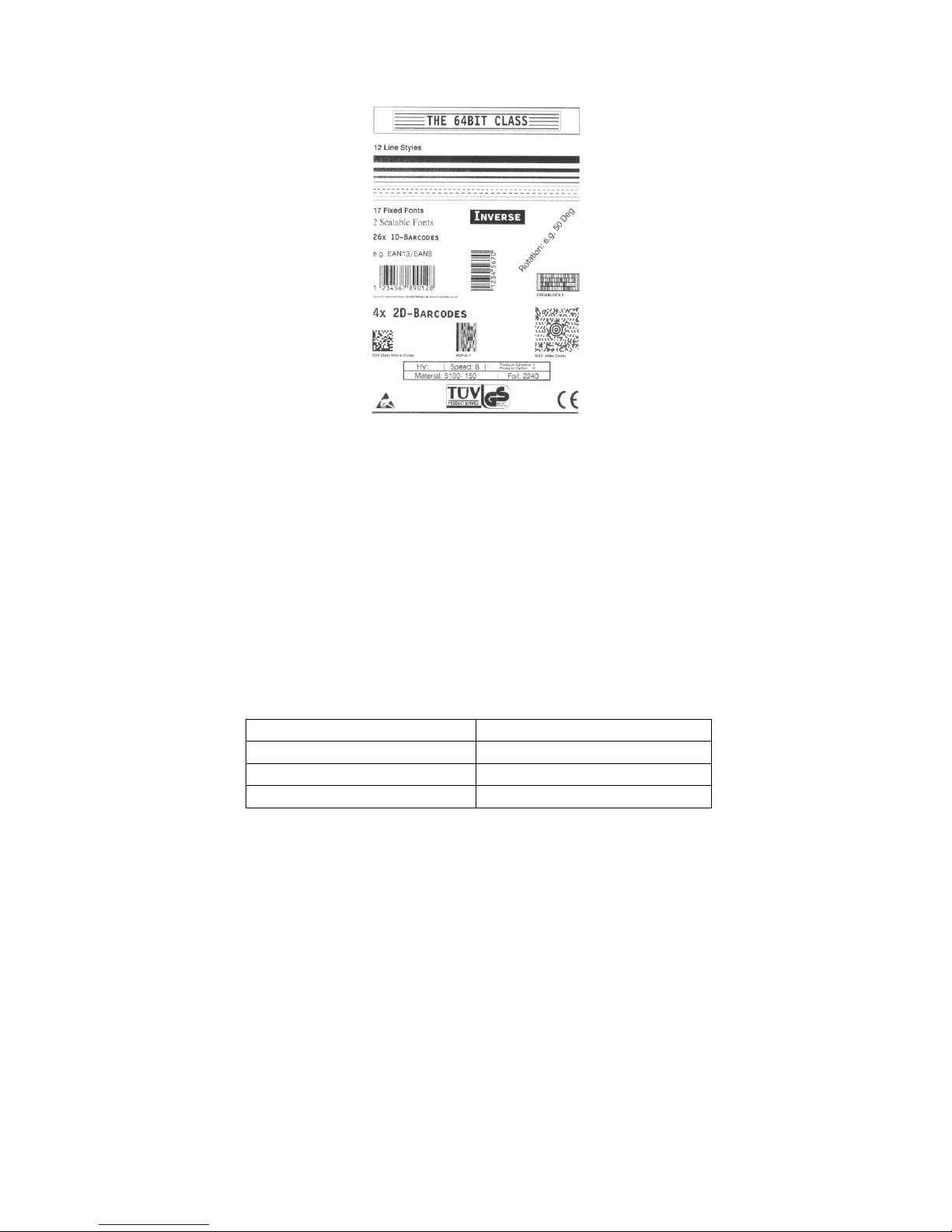
Reference label
Prints a label with some examples of barcodes, fonts, logos.
22
Page 24
Printer
Print Speed Range (in/sec)
64-04/05
2-16
64-06
2-14
60-08
2-9
PRINT PARAMETERS
Figure 6A: Sample Reference Label
Print speed
The print speed (material feed) can be adjusted according to the ribbon and material
combination being used in order to optimize the contrast depth and the density of the
print image.
inch/s Setting range: see table; Unit interval: 1 inch/s Default setting: 8 inch/s
Table 1A: Print Speed Ranges for Available Printers
Feed speed
The feed speed can be increased between print periods hereby reducing the total print
time, particularly with long labels with a minimum printed surface. Available feed
speeds are the same as print speed, please refer to Table 1A above for a complete
listing.
Setting: The value for the feed speed should not be set too high for print applications
with long calculating units (e. g. consecutive numbering). This can help to avoid
alternating between abrupt braking to 0 and acceleration to print speed, which can
affect print quality and also cause product to skew during transport. When altering the
23
Page 25

print speed, the feed speed is set equal to the print speed. If a different feed speed is
required, this must be reset either manually or using a job modifier within the labeling
software.
Material type
Definition of the materials used. A distinction is made between reel material and
gapped material (hole gaps, self-adhesive material with register gaps). The detected
gap position corresponds to the start of the label.
Endless: If material is to be used without gaps. Not recommended for the
Thermaprint 64.
Punched: If material is to be used with gaps (default setting)
Material length
The material length (label length) is the distance between the gaps, measured from the
front edge (beginning) of a label to the front edge of the next label.
xxx mm: Setting range: 5 mm to "max. length entry"; Unit interval: 0.1 mm
Default setting: 100 mm
Maximum length entry is dependent on the print head width and memory
configuration.
Material width
Zero position is the inside edge of the print head.
xxx mm: Setting range: "min. width" to "max. width"; Unit interval: 0.1 mm
Default setting: 100 mm
• Min. width: dependent on the printer type
• Max. width: dependent on print head width and memory configuration.
Print direction
Rotates the print according to the feed orientation of the product.
Foot first: (Default) Prints from the bottom to the top of the print image.
Head first: Prints from the top to the bottom of the print image.
24
Page 26

Punch offset
The zero position can be determined offset in millimeter units from the detected gap
position, as shown in Figure 7A.
Figure 7A: Visual representation of Punch offset setting.
xxx mm: Setting range: -5 to +max. label length; Unit interval: 0.1mm
Default setting: 0 mm
Maximum offset in feed direction: -5 mm
Minimum offset against feed direction: +max. label length
Bar code multip.
Bar code multiplication factor. Alters the bar code height by multiplication by a factor
of 1 to 10 (BCHI factor).
xxx mm: Setting range: 1 to 10; Unit interval: 1; Default setting: 1
The actual bar code height is calculated by multiplying the value defined in the label
layout by the bar code height enlargement factor.
Actual bar code height = (layout value + 1) * bar code height
Example: The bar code height value is set = 3. With the command in the label layout,
the value 4 is given as the bar code height (1 is standard). Result: (4 + 1) * 3 = 15
mm. The bar code is printed with a height of 15 mm.
UPC plain-copy
The position of the first and last digit in the plain-copy line underneath the bar code
can be adjusted as required.
Raised First and last digit of the UPCA or first digit with the UPCE are raised
(default setting).
In line All digits in the decoded line are in line under the code.
EAN Read line
<>Signs Read line enclosed in "<>" signs or terminated by a ">"-Sign (EAN
13).
Standard Read line without "<>" or ">" signs (default).
25
Page 27

EAN sep. lines
Parameter for controlling of EAN or UPC barcodes if they are printed without read
line.
With readl. only (Default) The separation bars at the beginning, end and in the
middle of the barcode are only long, if the barcode is printed with a read line.
Always long The separation bars at the beginning, end and in the middle of the
barcode are always long, regardless if the barcode is printed with or without read
line. The position of the barcode is the same as with the read line option switched
on.
Rotated Barcodes
Improves the readability of rotated (90° and 270°) bar codes.
Normal Normal printing without a special processing of rotated bar codes.
Optimized (Default setting) The line and gap widths of rotated bar codes are
modified in order to improve their readability.
X-print adjust
The zero point of the mask is moved in relation to the edge of the label on the X- axis,
i.e. lengthways to the material. If the setting is changed, while the print job is stopped,
the printer recalculates the format using the changed values. Caution with graphics. If
the graphics are shifted beyond the label border as a consequence of changing the
parameter X-print adjust, the part of the graphics which "juts out" will not print.
x inch/s Setting range: -5.0 to +5.0 mm; Unit interval: 0.1mm Default: 0.0 mm
• Maximum offset away from the edge of the label: +5.0 mm
• No offset: 0.0mm
• Maximum offset towards the edge of the label: -5.0 mm
Y–print adjust
The zero point of the mask is moved in relation to the gap position on the y-axis, i.e.
in the feed direction. If the setting is changed, while the print job is stopped, the
printer recalculates the format using the changed values. Caution with graphics, If the
graphics are shifted beyond the label border as a consequence of changing the
parameter Y-print adjust, the part of the graphics which “juts out” will not print.
x inch/s Setting range: -5.0 to +5.0 mm; Unit interval: 0.1mm Default: 0.0 mm
26
Page 28

• Maximum offset in feed direction: +5.0 mm
• No offset: 0.0mm
• Minimum offset against feed direction: -5.0 mm
Punch mode
Determine whether the sensor threshold level is set manually or automatically.
Automatic Use this setting for materials with a contrast zone or gap in the label.
Automatic is the default setting, suitable for all materials with which there is a
difference in the transparency between the product and gap of more than 2 values
Manual Use this setting for materials with several varying contrast zones.
Settings are made using the parameter PRINT PARAMETER > Punch level.
The range of the value automatically measured by the gap detection can be defined
specifically for the product material. This allows materials with high-contrast proof
points within the product to be processed, which would otherwise be measured as
'false' gaps by the system. The corresponding setting value is then equal to, or smaller
than, the value measured at the actual gap.
Punch level
Only shown if PRINT PARAMETERS > Punch mode is set to Manual mode. The
screen displays in real-time the current sensing value of the photoelectric sensor, and
allows for a default threshold to be manually set.
xxx Setting range: 0 to 255; Unit interval: 1
The value xxx stands for the current sensing value within the photoelectric switch
of the material which has just been inserted.
yyy Setting range: 0 to 255; Unit interval: 1
The value yyy stands for the current threshold level the sensor will use.
Example of correctly setting the threshold level:
Self-adhesive material with black bars lengthways across the label
• Reading:
– Masking paper: 30
– Masking paper + label: 60
– Masking paper + label + black bars: 190
• Setting value: 20
A setting value of 20 means that all readings over 20 are considered product,
therefore the printer will not see the differences between the labels.
• Setting value: 100
A setting value of 100 means that all readings over 100 are considered product,
therefore the printer will consider the black bars as the product, and nothing else.
• Setting value: 50
27
Page 29

A setting value of 50 means that all readings over 50 are considered product,
therefore the printer will consider the labels as the product, and the black bars will not
affect printing. A setting between the values of 30 and 60 is ideal for this application.
INTERF. PARAM.
Do not alter any of these settings within the interface parameters submenu without
consulting a service technician. Changing any of these settings can disrupt
communication between the printing computer and the printer. All of the parameters in
this section should be considered for service technician use only.
SYSTEM PARAMETERS
Foil end warning
Setting for a limit diameter for the ribbon roll. If the ribbon roll diameter falls below
the set value, the displayed message changes from
ONLINE X JOBS
to
FOLIE X JOBS
x.xx mm Setting range: 25.4 to 50.0 mm; Unit interval: 0.1 mm;
Default setting: 25.4 mm
Foil warn stop
Disabled (Default setting) Printer does not stop in case of a Foil end warning.
Enabled If a Foil end warning occurs, the printer will stop after the current label
and shows the status message. Press the online button to acknowledge the
message, then the feed button to continue printing.
Autom. dot check
Checks the print head for defective dots. The dot check can be carried out either after
powering on the printer or in print pauses between print jobs.
Continuous The dot check is carried out in pauses between print jobs. If a new
print job arrives before the dot check is done, the print job will be preferred. The
printer then interrupts the dot check and proceeds later with the next opportunity
at the last tested dot. The parameters Early dottest, Latest dottest, Dottestarea
28
Page 30

from, Dottestarea to determine the conditions under which the dot check is
executed.
The four specified parameters appear in the menu only if continuous has been
selected.
Power on only The dot check is preceded immediately after powering on the
printer. During testing the following blinking display message appears:
OFFLINE 0 JOBS
Head dot test
Off The automatic dot check is switched off.
Early dottest
Only displayed if SYSTEM PARAMETER > Autom. dot check = Continuous.
Determines the number of printed labels, after which the dot check should at the
earliest start.
Example: The setting 3 means that the dot check starts in the first printing pause after
three printed labels. After a successfully executed dot check starts the next dot check
again in the first pause after three printed labels.
after x label Setting range: 1 to 9999; Unit interval: 1; default setting: 10
Latest dottest
Only displayed if SYSTEM PARAMETER > Autom. dot check = Continuous.
Determines the number of printed labels, after which the dot check must be finished.
Example: The setting 5 means that the dot check has to be finished at the latest after
the fifth printed label. If necessary, printing is interrupted after the fifth label. After a
successfully proceeded dot check has the next dot check again to be finished after five
labels.
after x label Setting range: 1 to 9999; Unit interval: 1; default setting: 0
The setting "after 0 label" means, that the dot check will possibly be never finished
given a high utilization of the printer (A printing pause will never be forced).
The value for "Latest dottest" must be set higher than the value for "Early dottest"!
(exception: value 0).
Dottestarea from
Only displayed if SYSTEM PARAMETER > Autom. dot check = Continuous.
Limits the area of a print head, in which the dots are checked. The parameter sets the
lower border of the dot check area. The value equals the distance to the left print head
end in mm, looked at the print head from above (see Fig. 13).
x mm Setting range: refer to Tab. 3; Unit interval: 1; default setting: 0 mm
29
Page 31

Dottestarea to
Only displayed if SYSTEM PARAMETER > Autom. dot check = Continuous.
Upper border of the dot check area. The value sets the distance in mm to the left print
head end, looked at on the print head from above.
x mm Setting range: refer to Tab. 3; Unit interval: 1; Default setting: 0 mm
The value for "Dottestarea to" must be set higher than the value for "dottestarea
from"! (exception: value 0).
Print Interpret.
For Service Technician Use Only.
Character sets
For Service Technician Use Only.
Character filter
For Service Technician Use Only.
Light sens. type
The reflex photoelectric switch for labels with reflecting backings, or the normal
factory-fitted photoelectric switch for, must be defined according to the application.
Full Size Full Size photoelectric sensor (Adjustment range is the material width).
Reflex Reflex photoelectric sensor (for reflecting markings)
Punched Transparent photoelectric sensor (for gaps)
Head-sensor dist.
For Service Technician Use Only.
Sens. punch-LS
Sets the sensitivity of the material photoelectric switch.
xxx mm Setting range: 10 to 100%; Unit interval: 10% Default setting: 50%
Maximum sensitivity: 100%. for narrow gaps (perforations).
Minimum sensitivity: 1%. for clearly detectable gaps.
Too high a level of sensitivity can lead to gaps being detected which do not even
exist (on proofs, material thickness fluctuations, perforations etc.).
30
Page 32

Ribbon autoecon.
The ribbon feed can be interrupted during print periods with the ribbon automatic
economy parameter. This saves ribbon, particularly with long labels with a minimum
print area. The automatic function should only be activated with unprinted areas from
approx. 10 mm in length. A selection can be made between thermal transfer printing
and thermal direct printing. It is necessary to select the type of printing in order to be
able to switch over the ribbon end detection.
Thermal printing Thermal direct printing (Ribbon-end-LS switched off)
Activated Thermal transfer printing with ribbon automatic economy mode on.
Deactivated Thermal transfer printing with ribbon automatic economy mode off.
Ribbon economy limit
The ribbon economy limit determines the length of the printing free area on the label
from that on the ribbon economy automatic should be activated.
x.xx mm Setting range: xx up to 100,0 mm; Unit interval: 0,1 mm (the initial
value depends on the feed speed) Default-value: 5.0 mm
Turn-on mode
Operating mode of the printer after it has been switched on.
Online Printer starts in on-line mode.
Offline Printer starts in off-line mode.
Standalone Printer starts in standalone mode.
Interface delay
After switching from online to offline mode, the printer interface is deactivated. This
parameter offers a settable delay time before deactivating the interface.
xxxx ms Setting range: 0-1000; Unit interval: 100; Default setting: 0
Error reprint
If an error occurs while a label is printed, the last printed label will normally be
reprinted. In case of label layouts containing variable data like e.g. count fields, is
recommended.
Enabled Reprint in error cases (default setting)
Disabled No reprint in error cases.
31
Page 33

Single job mode
In single job mode (also stop mode) the printer stops after every job and waits until
the operator restarts the print process.
Deactivated Single job mode is switched off (default setting).
Activated Single job mode is switched on. The printer always displays "Start next
job", before starting a new print job. This requests the user to acknowledge by
pressing the Online button.
Head resistance
For optimum print quality, the individual print head resistance of the print head
installed in the device must be set once with this parameter. When replacing the print
head, the resistance value of the print head (to be read off from the print head) must
be entered again.
CAUTION! - Entering a false value can damage the print head!
«Read off the correct value from the print head and set it accordingly.
The value set here remains when the factory settings are carried out.
xxxx Ohm Setting range: 1000 to 1500 Ohm; Unit interval: 1 Ohm
Setting the print head resistance:
Setting:
1. From the print head, read off the resistance value to be set and make a note
of it (1000 to 1500).
2. In off-line mode press the Prog. button, display: PRINT INFO.
3. Press the Cut button until SYSTEM PARAMETER is displayed.
4. Press the Online button, display:
5. Press the Cut button until the following is displayed:
6. Press the Online button, set value is displayed.
7. Set the previously noted resistance value of the print head using the Feed and Cut
buttons.
8. Press the Online button to confirm the set value.
9. Press the Prog. button to return to the display OFFLINE 0 JOBS.
Temp. reduction
Allows the power supply to be reduced in the event of an increase in the print head
temperature, thereby ensuring an even print image.
xx% Setting range: 0 to 50%; Unit interval: 10%
The following setting alternatives are available:
• 0%: No temperature reduction (default).
32
Page 34

• xx%: Up to xx% temperature reduction with a hot print head.
Voltage offset
The voltage offset increases the head voltage and therefore the head temperature
which e.g. was set by Easy Plug command (HV).
xx% Setting range: 0 to 20%; Unit interval: 1% Default setting: 0%
Miss. label tol.
The maximum search length for gaps which cannot be found can be varied. In cases
of difficult gap detection (i.e. minimum variation in the light transparency, gap to
label), shortening the search path is to be recommended. Label loss resulting from
gaps not being detected can be reduced in this way. Printing does not take place
during the search process.
xx Setting range: 0 to 10; Unit interval: 1
• Example: 0 (Zero label length) A gap must be found after a printed label
otherwise an error message is given. This setting is for immediately detecting every
missing label.
Gap detect mode
After one of the following events, the printer must always search for a gap between
products:
• After switching the printer on
• After changing the label material
Manual The operator has to initialize the material always manually by pressing
the feed key several times.
Autom. Forward (Default for printers) The material initialization is always done
automatically, if necessary. There is no backward movement of the material
during the initialization.
Mat. end detect.
The material end detection can be deactivated for processing labels with gaps longer
than 15 mm, or if using material with a high fluctuation in light transparency (ST05 =
material end is displayed even though material is present).
CAUTION! - Reel material should not be processed when the material end
detection is deactivated! With this setting, printing continues on the print roller after
the end of the material, leading to shorter cleaning intervals or damage.
33
Page 35

Reflex Material end detection by means of a reflex sensor.
Transparent Material end detection by means of a transmission sensor.
Disabled No material end detection.
Periph. device
After installation, options must be selected under "Peripheral device" in order to be
assured of the corresponding sensor queries and printer reactions.
CAUTION! - Selecting an incorrect option can lead to malfunctions or
damage!
None No peripheral device is installed.
Cutter Sets the printer firmware to the cutter option. Selection permits access to
the cut parameters.
Rewinder Sets the printer firmware to the rewinder option. Selection permits
access to the rewinder setting parameters.
Tear-off edge Sets the printer firmware to the tear-off edge option. The punch is
fed forward to the tear-off edge.
Dispenser Setting for 64-xx dispenser version.
Singlestartquant
Determines the number of product to be printed after a single start signal has been
received.
xx Setting range: 1 to 10; Unit interval: 1
External signal
The parameter determines, if and how an incoming signal at the - optional - single
start connector will be interpreted.
Disabled Signal interpretation disabled.
Singlestart The signal triggers the printing of a single label. This setting may be
used e.g. for printing single labels by means of a foot switch or on-demand tray.
Stacker full The signal triggers the display of a status report and stops the printer.
This setting may be used when using a stacker (= stacker full signal).
Start mode
Ways of interpreting the start signal:
Level Labels of a certain print job are being printed as long as the signal level is
“high". When using a foot switch, labels are printed as long as the switch is
depressed.
34
Page 36

Edge The rising / falling signal edge triggers the printing of exactly one label
(Default setting).
See parameter Signal edge on page 23.
Start source
Choose a signal source for the start signal:
Foot switch Optional foot switch is used to generate the start signal.
Light barrier (Default setting) Photoelectric switch at the dispensing edge which
detects the taking off of the printed product.
USI USI interface (only with installed USI board)
Signal edge
This parameter determines either the falling or the rising edge of an incoming signal
as trigger.
Falling edge The falling signal edge triggers a certain printer reaction.
Rising edge The rising signal edge triggers a certain printer reaction.
Signal / buzzer
On Tone signal activated
Off Tone signal deactivated
Special Function
Delete job
Press the Online-key to cancel the active print job.
Delete spooler
Press the Online-key to delete all print jobs contained in the spooler.
Factory settings
All parameters are preset ex works to values specific to each device type. These
factory settings can be restored at any time. All parameters are then overwritten by
the factory settings. The currently valid settings can be checked using PRINT INFO >
printer status.
CAUTION! - All data present in the spooler, including data belonging to an
35
Page 37

Ribbon
Heat (%)
828
60
89J
60
811
30
403
60
501
110
45
110
interrupted print job, is deleted!
Service Function
Do not adjust any of the settings in this sub-menu without contacting a service technician.
Heat Settings
When printing, the heat should be set dependent on the ribbon being used. The optimal
heats for various ribbons can be seen in the table below.
36
Page 38

Appendix B: External Attachments
Power Stacker
Parts
6 red screws (4 large, 2 small)
1 sheet metal shield
1 stacker housing
2 stacker rods
2 4mm screws
1 stacker tray
Magnetic guide(s) (standard: could change if custom design needed)
Assembly
1. Attach sheet metal shield onto the front of the bosch frame using the 2 small red
screws provided.
2. Screw stacker rods onto the stacker housing.
3. Lubricate O-Ring grommets on the stacker tray using Windex.
4. Slide the stacker tray onto the stacker rods and screw in the 2 4mm screws into
the ends of the stacker rods.
5. Position the magnetic guide(s) in such a way to allow for product to stack as
desired.
6. Plug the DB-15 cable from the stacker into the front port on the printer.
7. Secure the screws in the DB-15 connector to the printer.
CAUTION! - Make sure printer is off when plugging the stacker in,
otherwise circuitry could be damaged!
8. Attach stacker to the bosch housing by inserting 2 of the provided large red
screws through the holes on the inside of the housing. Tighten to secure stacker to
printer.
Single-Start Catch Tray
Parts
2 red-capped screws
1 single-start catch tray
Assembly
Attach the tray to the front of the printer using the 2 red screws.
Page 39

Options
Turn Single-Start Function On/OFF
Go into the menu and go to System Parameters > Periph. Device > Single
Start (to enable function) or none (to disable function) and then press
Online to select.
Change the number of products printed at a single time
Go into the menu and go to System Parameters > Singlestartquant and
then select the number of products desired to print at a time (default is 1).
Press Online to apply the desired number.
Page 40

Part Name
Part Number
1
Printhead Pressure Selector
98220
2
Ribbon Take-Up Mandrel (64-04/05, 64-06, 64-08)
98319, 98672, 99938
3
Ribbon Supply Mandrel (64-04/05, 64-06, 64-08)
98318, 98673, 99937
4
Seperator Gap Adjustment Knob
99000
5
Ribbon Drive Platen (64-04/05, 64-06, 64-08)
98171, 98584, 99608
6
Ribbon Guide (64-04/05, 64-06, 64-08)
98137, 98589, A0214
7
On Demand Catch Tray (optional)
99013
8
Press Roller
A5853
9
Seperator Assembly (Blue Wheel)
09-0558-00
10
Product Guide
99012
11
Printhead Assembly (4in)
A0978
12
Bottom Print Platen (64-04/05, 64-06, 64-08)
A3413, A4396, A4393
13
Feed Ramp
99002
14
Feed Wheel (Grey Rubber)
99003
15
Feed Wheel (White Silicon)
99004
16
Pinch Roller (Truck)
99007
17
Blue Transport Belt (Inside)
99009
18
Pinch Roller Wheel (Truck)
99032
Appendix C: Parts Callout
Page 41
1 5 11
12
7
3 2 16
18
9
8
17 4 6
10
13
14
15
Page 42

Part Name
Part Number
1
Printhead Pressure Selector
98220
2
Ribbon Take-Up Mandrel (64-04/05, 64-06, 64-08)
98319, 98672, 99938
3
Ribbon Supply Mandrel (64-04/05, 64-06, 64-08)
98318, 98673, 99937
4
Seperator Gap Adjustment Knob
99000
5
Product Guide Adjustment Knob
99001
6
Printhead Hold-Down Screws
A1004
7
Ribbon Drive Platen (64-04/05, 64-06, 64-08)
98171, 98584, 99608
8
Ribbon Guide (64-04/05, 64-06, 64-08)
98137, 98589, A0214
9
On Demand Catch Tray (optional)
99013
10
Decurler (optional)
99014
11
Press Roller
A5853
12
Feed Assembly
Call for details
13
Seperator Assembly (Blue Wheel)
09-0558-00
14
Seperator Assembly (Grey Wheel)
99011
15
Product Guide
99012
16
Printhead Assembly (4in)
A0978
17
Printhead Assembly (5in)
A0979
18
Printhead Assembly (6in)
A0980
19
Printhead Assembly (8in)
A0981
20
Snap-in Bearing (In Support Gate of 10” Printer)
98847
21
ME500 Power Supply (10” Printer)
A7980-09
22
Power Supply Assembly (6” Printer)
A8328
23
Steel Interlock Switch Engager
98202
24
Plastic Spacers for Ribbon (5mm, 6mm, 8mm)
A4522, A0778, 98154
25
Bottom Print Platen (64-04/05, 64-06, 64-08)
A3413, A4396, A4393
26
Quick Change Print Platen (64-04/05, 64-06, 64-08)
A3413QC, A4396QC, A4393QC
27
Punch Sensor
A1958
28
Reflective Sensor
A1504
29
Feed Ramp
99002
30
Feed Wheel (Grey Rubber)
09-0556-00
31
Feed Wheel (White Silicon)
09-0585-00
32
Feeder Belt
99005
33
Solid Motor Mounts
99006
34
Transport Drive Motor Belt
95931
35
Pinch Roller (Truck)
99007
36
Blue Transport Belt (Smooth)
99008
Appendix D: Replacement Parts List
Page 43

37
Blue Transport Belt (Rough)
99009
38
Extension Feed Tray
99015
39
Static Brush
99016
40
Static Brush Ground Cable
99017
41
Red Capped Thumb Screws (4mm)
99018
42
Red Capped Thumb Screws (1/4”)
99019
43
Feed Shaft (6” Printer)
99020
44
Feed Shaft (10” Printer)
99021
45
Belt Idler Shaft (6” Printer)
99022
46
Belt Idler Shaft (10” Printer)
99023
47
Drive Shaft (6” Printer)
99024
48
Drive Shaft (10” Printer)
99025
49
Belt Roller
99026
50
Belt Adjust Post
99027
51
Belt Adjust Sleeve
99028
52
Support Post
99029
53
Frame Spacer (6” Printer)
99030
54
Frame Spacer (10” Printer)
99031
55
Pinch Roller Wheel (Truck)
99032
56
Mount Bar
99033
57
Pinch Roller Mount
99034
58
Separator Bar
99035
59
Interlock Cover Assembly
99036
60
Hold Down Spring – Standard
99037
61
Hold Down Spring – Wide
99038
62
Feed Paddlewheel – Aluminum
99039
63
Feed Paddlewheel – Rubber
99040
64
Stacker Carriage
99200
65
Stacker Bearings
99201
66
Stacker Tray Short
99202
67
Stacker Tray Long
99203
68
Stacker Magnetic Pole Guides
99204
69
Standard Stacker Guide
99205
70
Stacker Board
99206
71
Stacker Elevator Cable
99207
Page 44
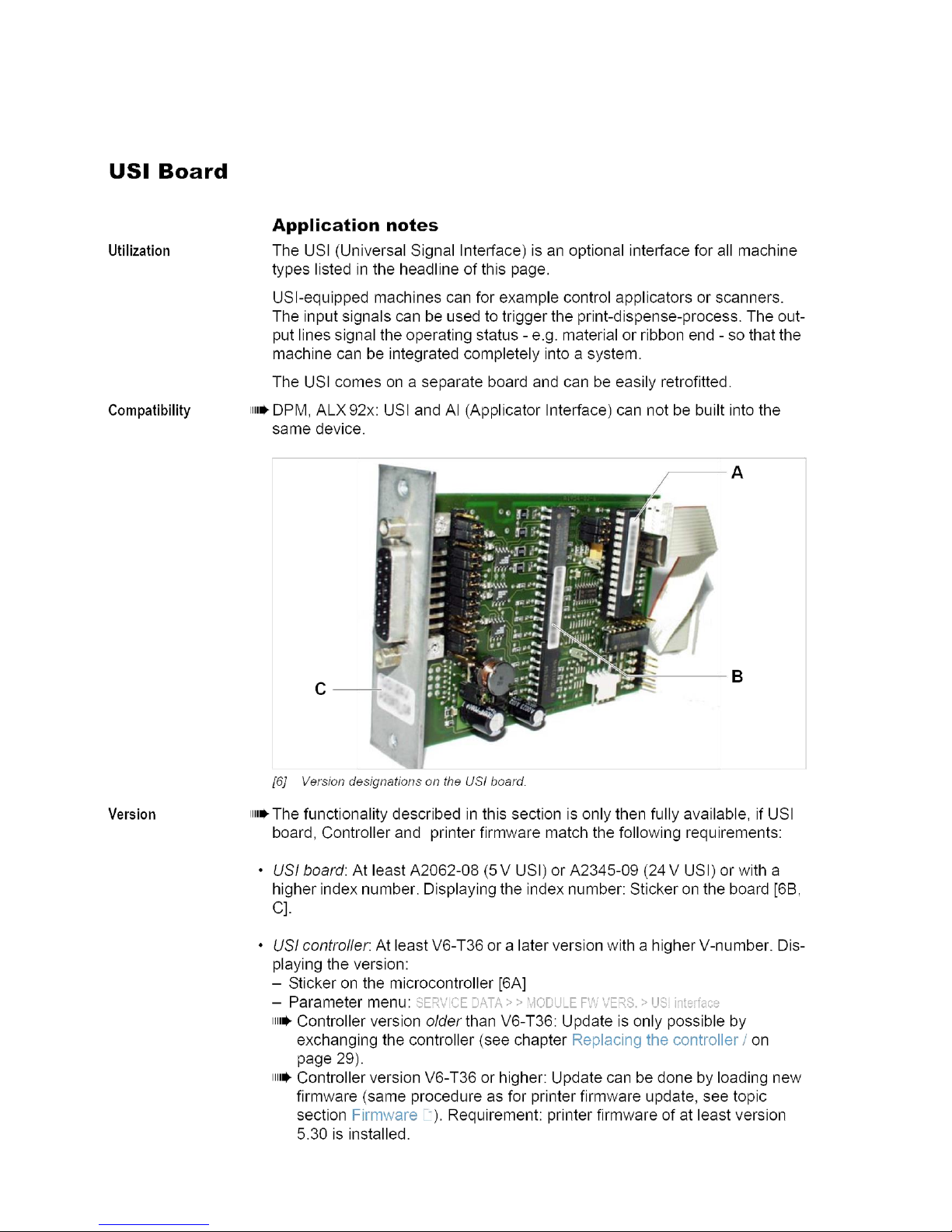
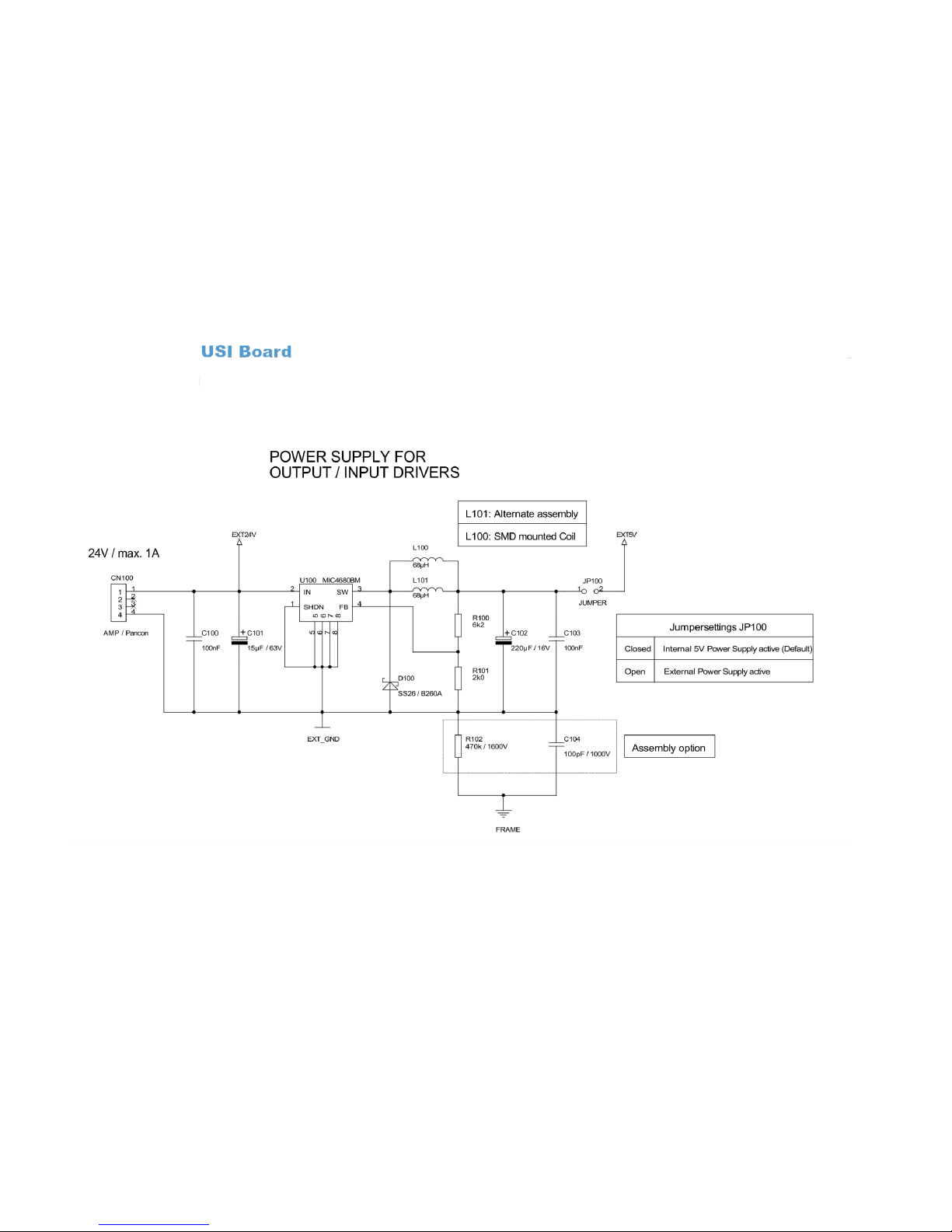
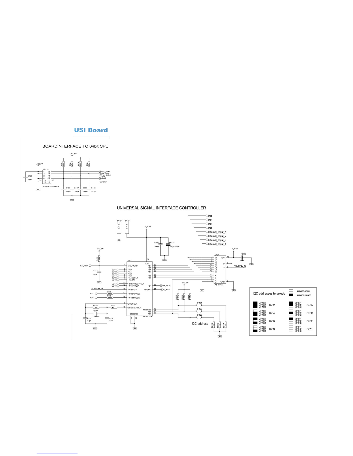
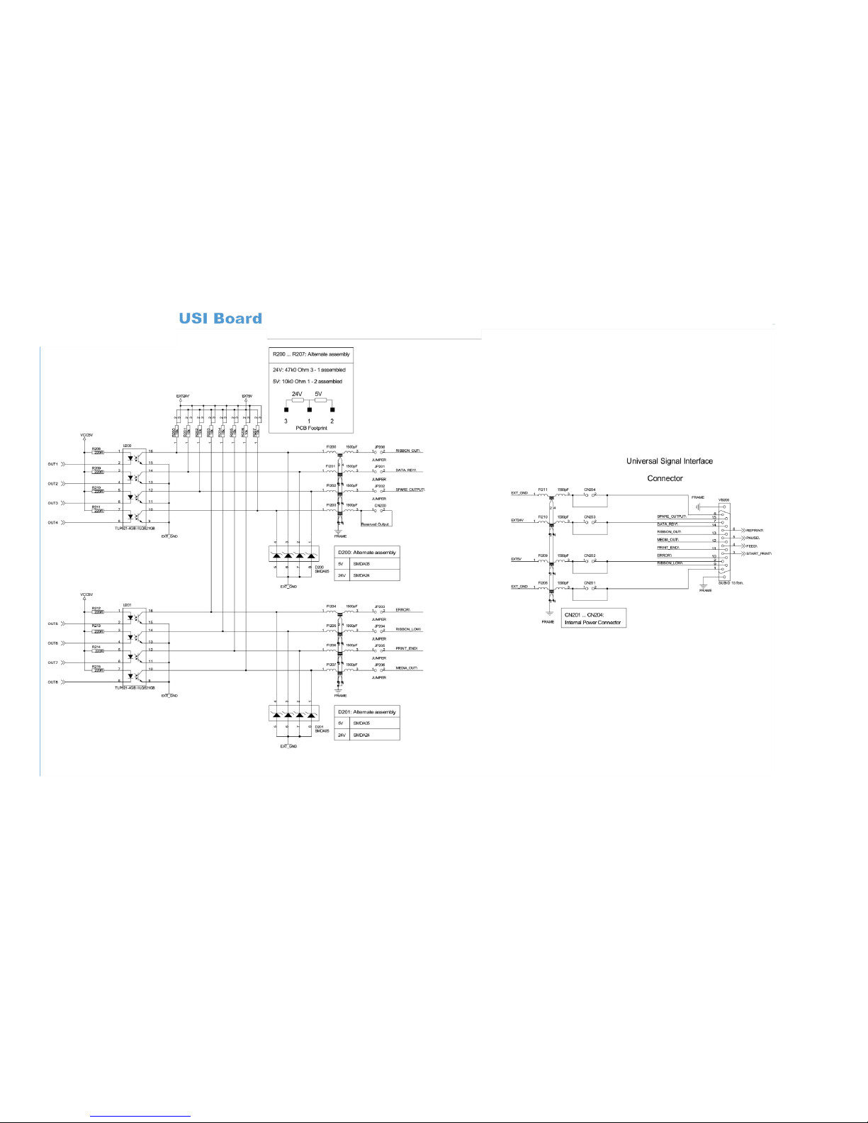
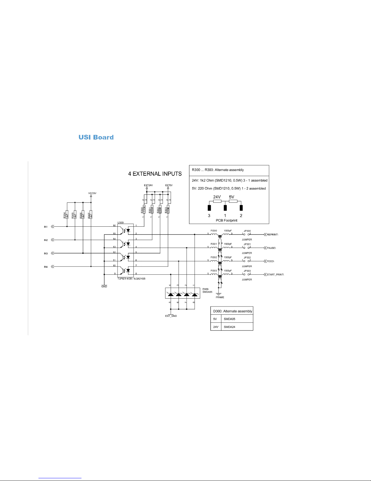
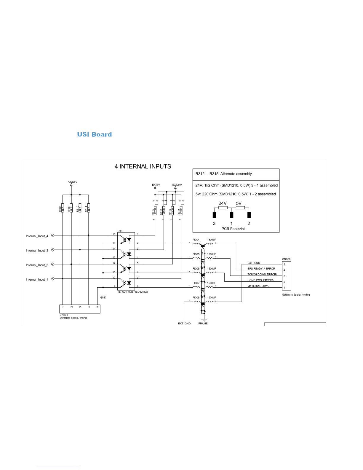
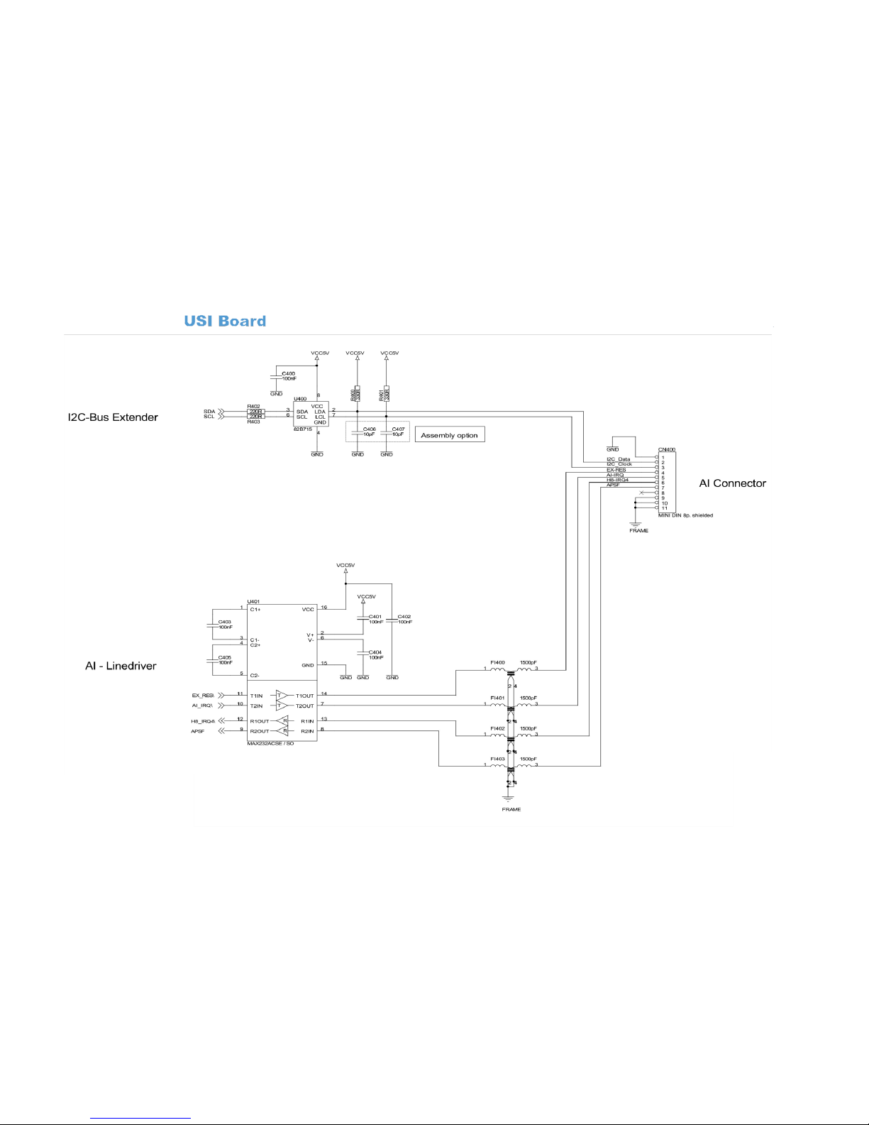
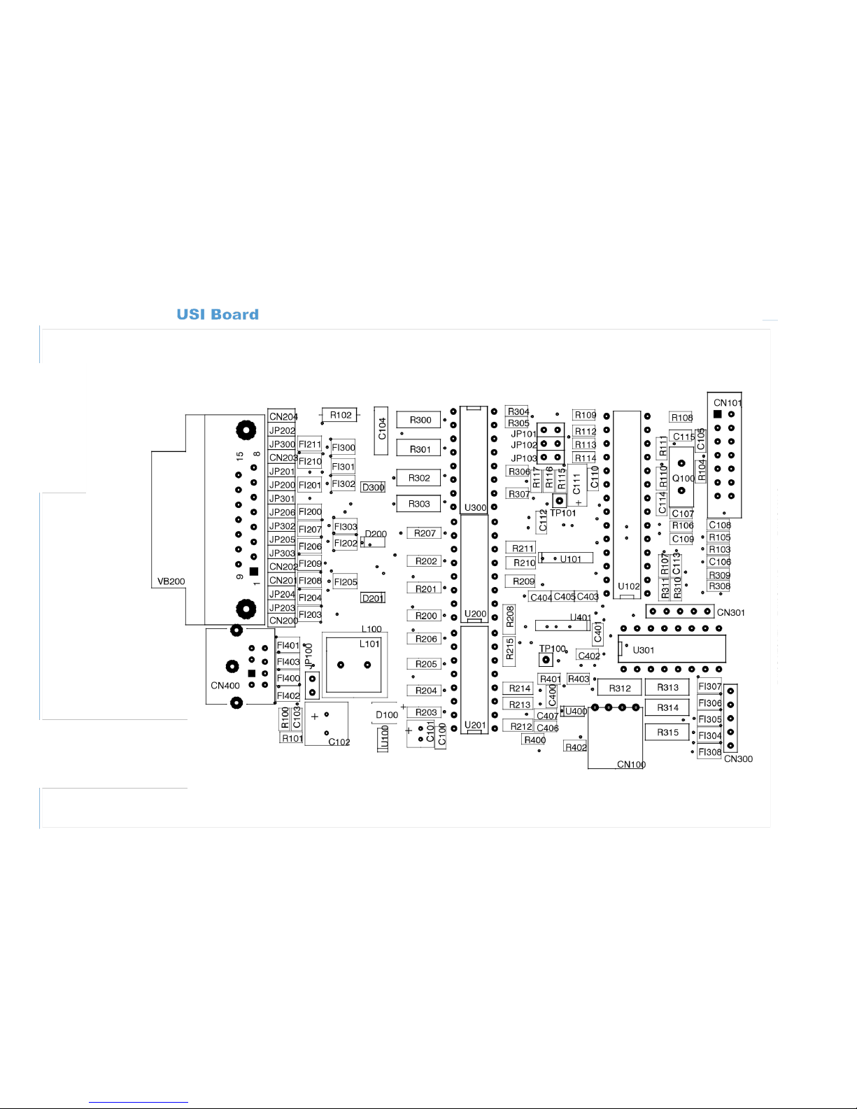
Appendix E: Universal Interface Board (Optional)
Page 45
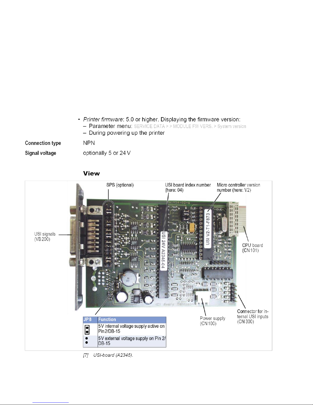
Page 46
Page 47
Page 48
Page 49
Page 50
Page 51
Page 52
Page 53
Page 54
Page 55
Page 56
Page 57
Page 58
Page 59
Page 60
 Loading...