

Page 1
i
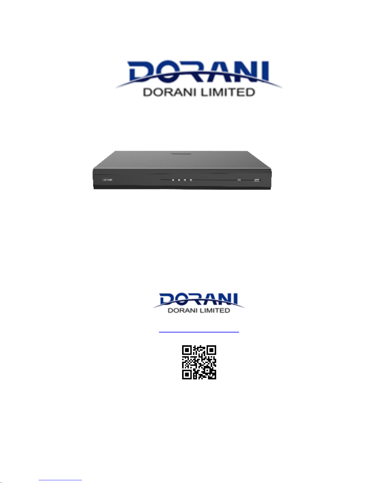
NVR BASIC USER GUIDE
DORIP10 - DORIP11 - DORIP12
WWW.DORANI.COM.AU
Dorani (PJM Sales) – 03 9357 0942d
4/1 Merri Concourse, Campbellfield, Victoria 3061
Page 2

ii
Contents
Preface ....................................................................................................
Part I Local Operations .............................................................................
1 Before You Begin ...................................................................................
Login ................................................................................................................
Local Operations .............................................................................................
2 Initial Configuration ...............................................................................
Preparation .....................................................................................................
Wizard .............................................................................................................
3 Network & APP Phone Connection ........................................................
Network ..........................................................................................................
Data Speed and Usage ....................................................................................
P2P App Connection........................................................................................
4 Live View ...............................................................................................
Live View Status ..............................................................................................
Window Toolbar .............................................................................................
Screen Toolbar ................................................................................................
Shortcut Menu ................................................................................................
Sequence Operation .......................................................................................
Zoom ...............................................................................................................
Image Configuration .......................................................................................
Preview Configuration ....................................................................................
5 Playback ................................................................................................
Instant Playback ..............................................................................................
Playback Toolbar .............................................................................................
Playback by Camera and Date .........................................................................
Playback in Corridor Mode..............................................................................
Page 3

iii
Playback by Tag ...............................................................................................
Playback by Event ...........................................................................................
Playback by Smart Search ...............................................................................
Playback by External File .................................................................................
Playback by Image ...........................................................................................
File Management ............................................................................................
6 Backup ..................................................................................................
Recording Backup ...........................................................................................
Image Backup ..................................................................................................
7 System Configuration .............................................................................
Basic Configuration .........................................................................................
Time Configuration .........................................................................................
User Configuration ..........................................................................................
Security Configuration ....................................................................................
8 Channel Configuration ...........................................................................
Channel Management .....................................................................................
OSD Configuration ..........................................................................................
Image Configuration .......................................................................................
Privacy Mask Configuration ............................................................................
9 System Maintenance .............................................................................
System Information.........................................................................................
Network Information ......................................................................................
Log Query ........................................................................................................
Import/Export .................................................................................................
System Restoration .........................................................................................
Automatic Maintenance .................................................................................
System Upgrade ..............................................................................................
10 Shutdown ............................................................................................
Page 4

1
Preface
This manual describes how to use your NVR locally or on the Web
interface.
In this manual, the terms IP camera and IPC refer to the same thing:
network camera, which requires a connection to the network. And the
IP device mentioned in this manual refers to an IP camera (also known
as network camera) or a Digital Video Server (DVS).
Part I Local Operations
An NVR supports two types of operations: local operations and web-
based remote operations. With local operations you connect a monitor
and a mouse to the NVR and use the mouse to operate. If your NVR has
buttons on the front panel or is delivered with a remote control, you
may also control your NVR by pressing the front panel buttons or using
the remote control.
The NVR has an embedded web server and allows web-based
operations. To do this, you need a PC that has a network connection to
the NVR and is installed with a web browser. You just need to navigate to
the NVR's IP address and log in to the Web interface like you log in to
the system locally.
This section describes local operations.
1 Before You Begin
Please be aware that the parameters that are grayed out on the system
user interface (UI) cannot be modified. The parameters and values
displayed may vary with device model, and the figures in this manual are
for illustration purpose only.
Page 5

2
Login
Use the default username admin and password 123456 for your first
login.
CAUTION!
The default password is intended only for the first login and should be
changed to a strong one containing at least eight characters including
uppercase and lowercase letters, digits and symbols after your first login
to ensure security.
1. Right-click anywhere in the window and then choose Menu. The
login dialog box is displayed.
2. Select the username from the drop-down list, enter your password,
and then click Login.
Local Operations
You can refer to Initial Configuration and complete a quick configuration.
NOTE!
Unless otherwise specified, all operations described in this manual are
performed with a mouse by the right hand. See Mouse Operations for
details.
Mouse Operations
Table 1-1 Mouse Operations
Name
Action
Description
Left
button
Click
⚫ Select or confirm an item.
⚫ Select to edit digits, symbols, upper-case or
lower-case letters in a field.
Double-click
Enter or exit full screen mode in live view.
Page 6
3
Name
Action
Description
Drag
Draw or move a rectangle on the screen, for
example, a motion detection area.
Right
button
Click
⚫ Show the shortcut menu.
⚫ Exit zoom.
⚫ Exit the current window when Cancel or
Exit is displayed.
Wheel
Scroll up or
down
Scroll up or down a list or a window; or zoom in
or out on a playback progress bar.
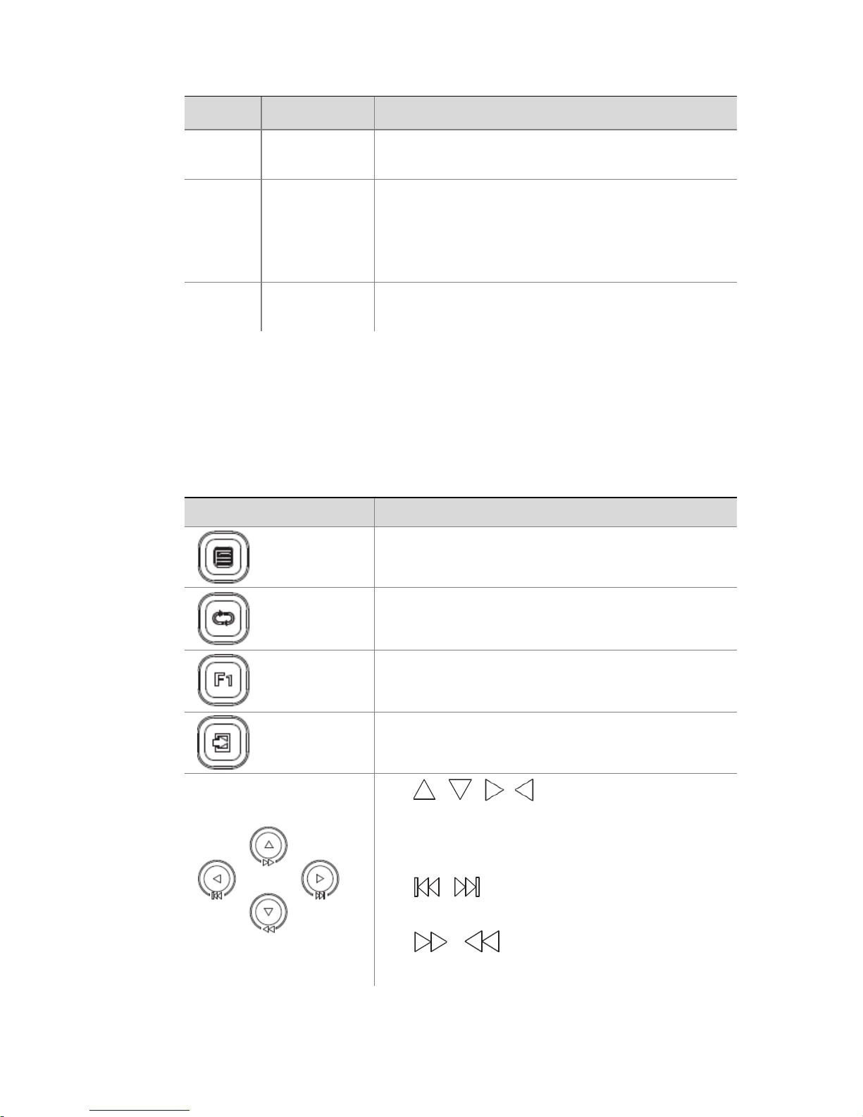
Front Panel Buttons
The front panel buttons may vary with NVR model.
Table 1-2 Front Panel Buttons 1
Button
Description
Display the main menu.
Switch to the next tab on the screen or switch the
input method.
Auxiliary function button.
Exit the current window.
⚫ , , , : Switch windows or menu
items; or control rotation directions of a
PTZ camera when the PTZ toolbar is closed.
PTZ stands for pan, tilt, and zoom.
⚫ , : Rewind or forward 30 seconds
in full screen.
• , : Variable-speed forward or
rewind in full screen.
Page 7
4
Button
Description
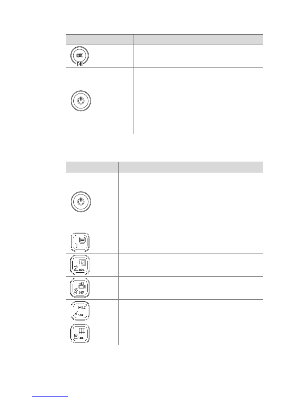
Confirm an operation, or start/pause the
playback.
Press this button to start up or shut down the
NVR.
To shut down, press this button and hold for at
least 3 seconds till a message appears on your
monitor. Click Yes.
Note:
This shutdown operation can be performed only
when you have logged in to the system.
Table 1-3 Front Panel Buttons 2
Button
Description
Press this button to start up or shut down the NVR.
To shut down, press this button and hold for at least 3
seconds till a message appears on your monitor. Click
Yes.
Note:
This shutdown operation can be performed only when
you have logged in to the system.
Enter 1; or display the main menu.
Enter 2, A, B, or C; or start instant playback.
Enter 3, D, E, or F; or start manual recording.
Enter 4, G, H, or I; or enter the PTZ control interface.
Enter 5, J, K, or L; or switch the screen layout in live
view or playback mode.
Page 8
5
Button
Description
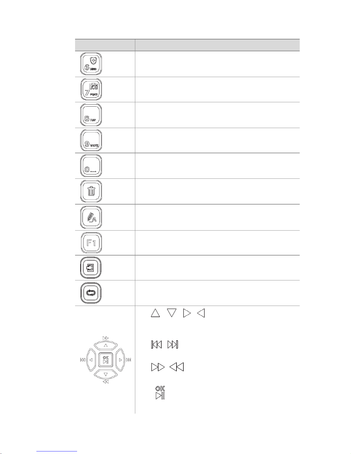
Enter 6, M, N, or O; or enable or disable arming.
Enter 7, P, Q, R, or S; or take a snapshot.
Enter 8, T, U, or V.
Enter 9, W, X, Y, or Z.
Enter 0 or a space.
Delete
Switch the input method.
Auxiliary function button.
Exit the current window.
Switch to the next tab.
• , , , : Switch windows or menu
items; or control rotation directions of a PTZ
camera when the PTZ toolbar is closed
• , : Rewind or forward 30 seconds in full
screen.
⚫ , : Variable-speed forward or rewind in
full screen.
⚫ : Confirm an operation; or start or pause
playback.
Page 9
6
2 Initial Configuration
Preparation
⚫ Make sure that at least one monitor is correctly connected to the
VGA or HDMI interface on the rear panel of the NVR.
⚫ Verify that the hard disk(s) are correctly installed. For detailed
steps to install a hard disk, please refer to the quick guide shipped
with your NVR.
Wizard
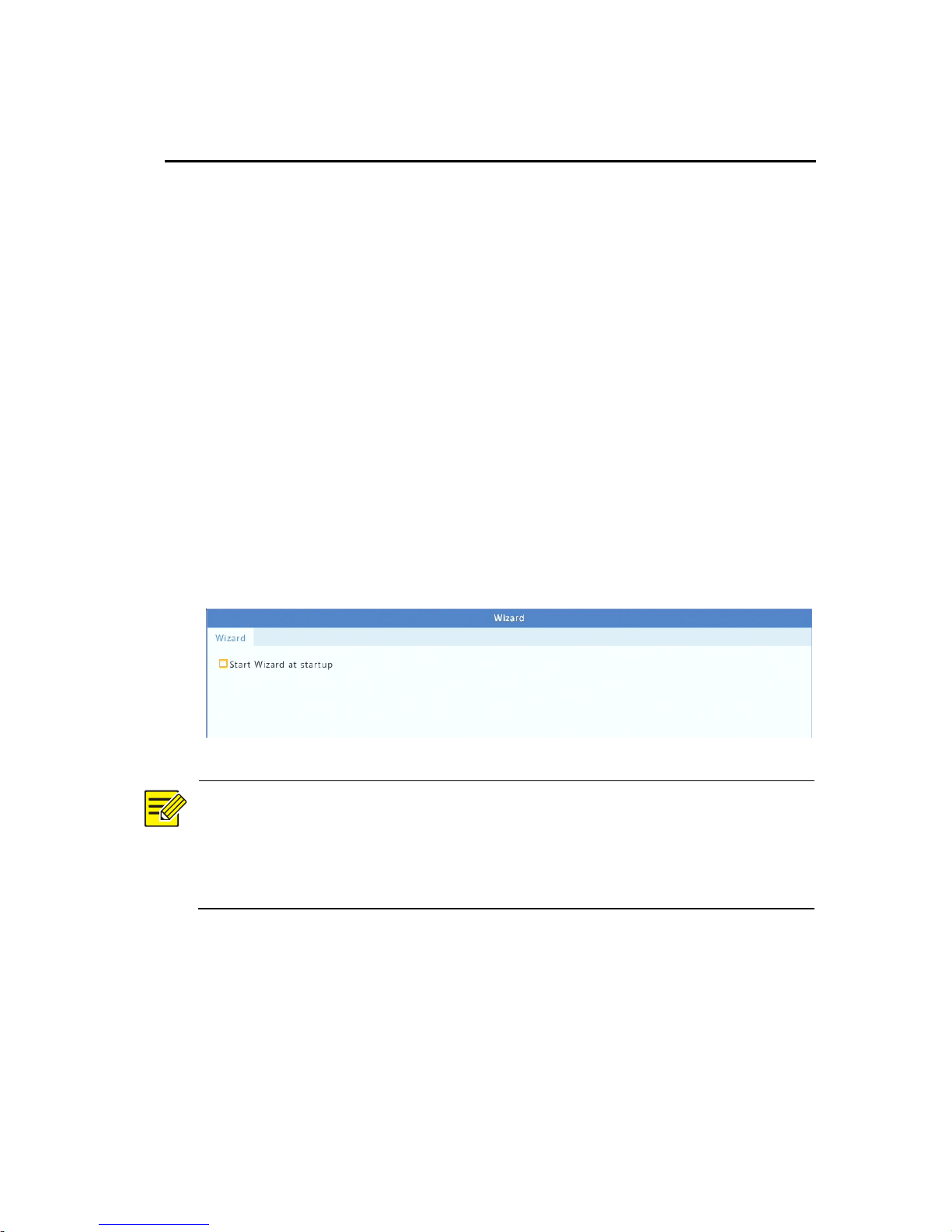
The wizard can guide you to complete the most basic setup. The wizard
may vary with device model and other factors. The following shows an
example.
1. Enable or disable the wizard as needed and then click Next.
NOTE!
⚫ You may change the setting under System > Basic.
⚫ If a QR code is displayed, you may scan the code to download an
app and use the app to control your NVR.
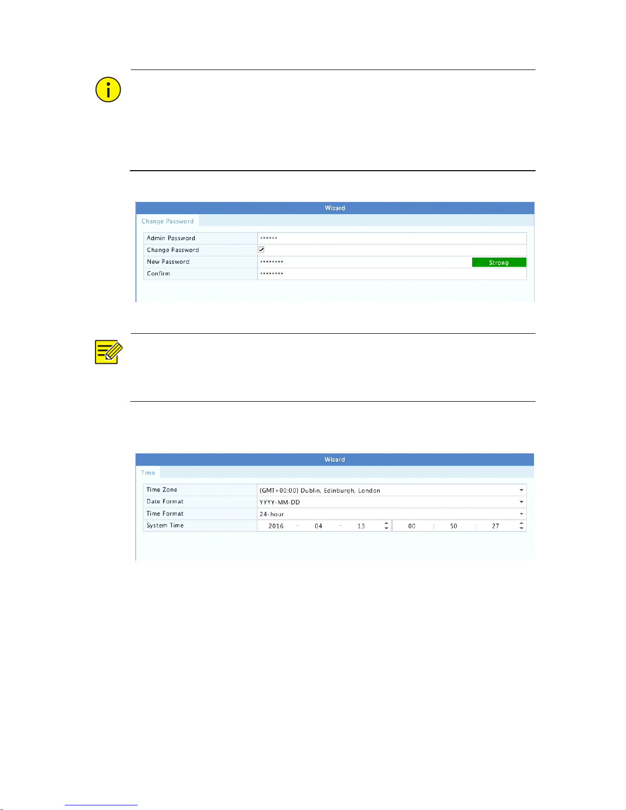
2. Enter the default admin password 123456 and then click Next.
Page 10
7
CAUTION!
The default password is intended only for the first login and should be
changed to a strong one containing at least eight characters including
uppercase and lowercase letters, digits and symbols after your first login
to ensure account security.
NOTE!
For RAID models, a window appears following this step for RAID
configuration.
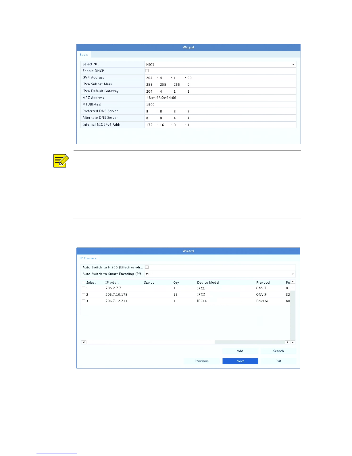
3. Complete time information and then click Next.
4. Set the IP address, subnet mask, and default gateway. Use the
default settings for other parameters unless modification is
necessary. Review the settings and then click Next.
Page 11
8
NOTE!
⚫ DHCP is enabled by default.
⚫ If your NVR has more than one Network Interface Card (NIC), you
may configure the NICs and choose one for default route.
⚫ An internal IPv4 address can be configured if your NVR has PoE
ports or switching ports.
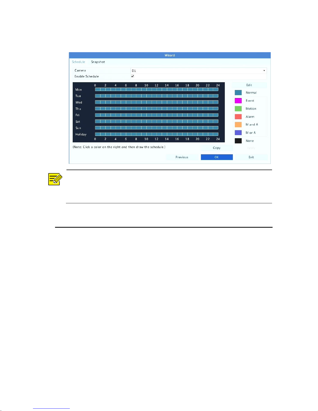
5. Click Next.
Page 12
9
6. Set a recording/snapshot schedule and then click OK.
NOTE!
You may also edit wizard settings by clicking Wizard under
System > Basic.
3 Network and Phone Connection
General
Your recorder is pre-set to be DHCP which when plugged into a router
with internet connection it should automatically be assigned an IP
address. Once the recorder is ONLINE to the internet a P2P connection
can be made to the device for Mobile Phone device connection.
Please note: if there is any network connection problems, this could be a
modem configuration setting NOT a recorder setting. This would need to
have port forwarding set up for the connection to be made.
Page 13

10
It is recommended that only IT professionals do this style of connections
as incorrectly changing settings in your modem can cause connection
issues for all devices.
Data Speed & Usage
When you are streaming the footage to your mobile device please be
aware that this is using the upload data of your internet service and
download data of your mobile device. If this data usage falls outside of
your allocated plan, charges could occur.
The system relies on the UPLOAD speed of the internet at the device
location and the DOWNLOAD speed at the mobile device. There is 3
different rates of camera quality; Smooth (low data) SD (medium data)
and HD (High data). Smooth is recommended for standard viewing; the
others are recommended when looking for more detailed picture
quality.
Viewing at higher picture quality at a low internet speed may cause
video feeds to load slower or jump in playback or live view.
Get the App
Option one: Search "Dorani IP Viewer" on Google Play or App Store.
Option two: Scan the QR code on the device or Below.
Page 14
11
Getting Started
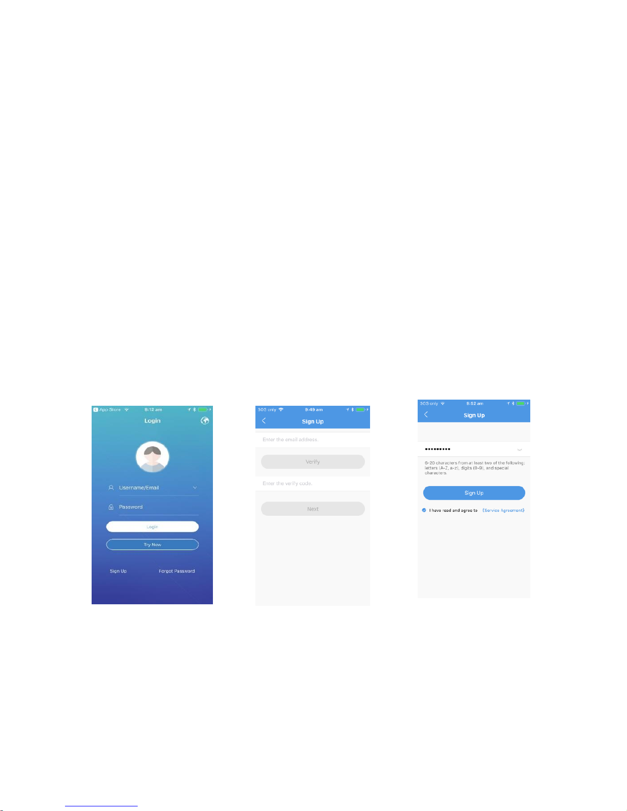
If this is the first time using the App, or you have not registered a P2P
account with the server. If you already have signed up an account,
please proceed to adding a device.
Before you proceed, please ensure you have a valid email address ready
and the ability to receive an emails from this account at time of set up.
This email will be the MAIN administrator of the account.
App Connection
If a successful connection is achieved the ‘cloud’ light will appear on the front
panel of the NVR
Step 1 Step 2 Step 3
Enter a Password for your
Account
Press Sign Up on Home Page
Enter the Email address and
Press Verfiy – Then enter the
Verify code that is emailed to
the email address entered
Page 15
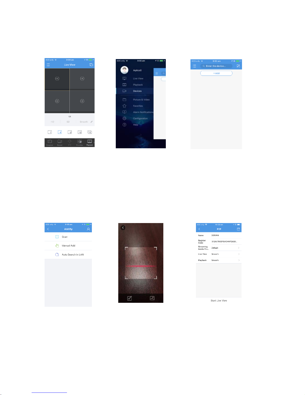
12
Scan the QR Code from either
- Start Up Wizard
- Bottom of NVR
- NVR Menu
(Settings/Network/P2P)
Name the
Device
Press Start
Live View
Step 4 Step 5 Step 6
Step 7 Step 8 Step 9
Select ‘+Add’
Select ‘ Menu’
A pop up window may appear asking
you if you would like to add a device.
Select ‘ADD’ and proceed to step 7
Select ‘Devices’
Select ‘ Scan’
DO NOT USE Auto Search – This
will only allow the device to
work on local WiFI
Page 16

13
Subsequent Users
If you have additional users wishing to view on their own mobile device,
the same login can be used for subsequent users. The users only need to
login using the same username and password as the initial user.
If the user wishes to have their own login they can follow steps 1-3 ONLY
The first (ADMIN) user can then utilize the share function in their APP to
“share” the device with others.
De-Regsitering
If you no longer want to use the APP, or no longer wish to connect to
that device or want to register a new user as the ADMIN- you can either:
1) delete the device on the APP itself (this will delete it from the local
phone and ANY shared accounts)
2) Delete it in the NVR Menu – Settings – Network – P2P
Once there is no Devices connected to the recorder the ‘Cloud’ light will
disappear from the front panel of the NVR.
4 Live View
Live View Status
The following icons are used to indicate alarms, recording status, and
audio status in a live view window.
Page 17
14
Table 4-1 Live View Window Icons
Icon
Description
Tampering alarm
Motion detection alarm
Recording
Two-way audio
Turn on audio
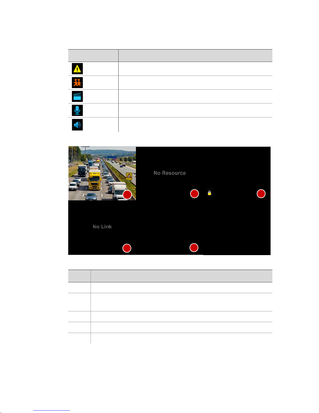
Normally, live video is displayed, but other situations are also possible.
No.
Description
1
The IP device is online, and live video is displayed.
2
The IP device is online, but the NVR has insufficient capacity to
decode streams from the IP device.
3
No permission to view live video from the IP device.
4
The IP device is offline.
5
No IP device is linked to the window.
1
2
4
3
5
Page 18
15
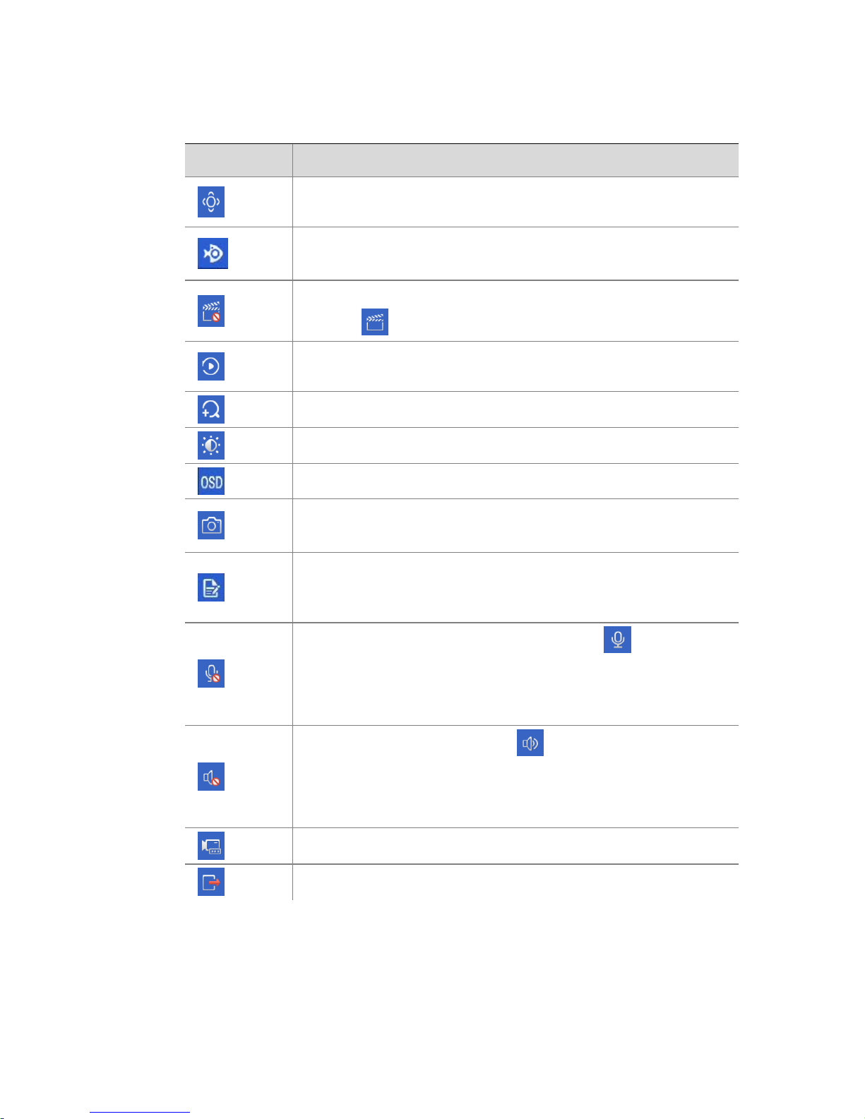
Window Toolbar
Icon
Description
Available for PTZ cameras only. Click to display the PTZ
control window.
Set mount mode and display mode for fisheye camera.
This icon appears only for fisheye cameras.
Record live video in the window to the hard disk.
Clicking stops recording.
Click to play video recorded during the past 5 minutes and 30
seconds.
Zoom in on an area of interest.
Click to edit image settings.
Click to set OSD.
Click to take a snapshot. The window borders will flash white.
You may view and back up snapshots under Backup > Image.
Rest your mouse pointer on the icon to view bitrate info; click
this button to view the camera ID and IP address or to change
the username and password used to connect the camera.
Start two-way audio with the camera. Click to stop. The
sound volume is adjustable.
Note: Correct audio input and output connections are
required.
Click to turn on audio. Clicking turns off audio. The sound
volume is adjustable.
Note: When you turn on audio in the current window, audio
of the previous window is turned off.
Click to link the window to another IP device.
Exit
Page 19
16
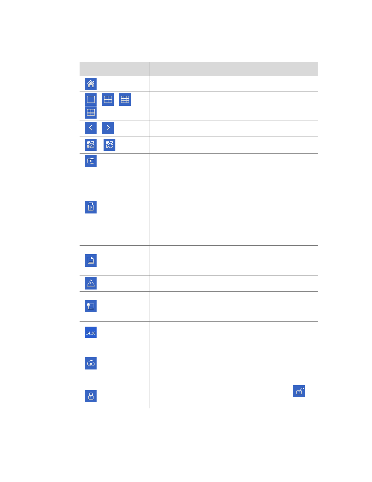
Screen Toolbar
Icon
Description
Click to access the main menu.
/ / /
Select the screen layout.
/
Previous or next screen.
/
Start or stop sequence.
Playback.
Click to open the USB Device window and perform
USB related operations. The window offers quick
access to multiple windows, and it pops up
automatically if a USB storage device is plugged in
when the NVR is restarting or when the preview
window is displayed.
This button is effective only when a USB storage
device is plugged in.
Rest the mouse pointer on this icon to view encoding
information including frame rate, bit rate, and
resolution; or click to view camera status.
Click to view device alarm status and camera status.
Rest the mouse pointer on it to view NIC card
information. Or click this icon to edit basic network
settings.
Rest the mouse pointer on it to view the date. Or click
this icon to edit time settings.
Available to certain NVR models.
Click to display the cloud service window. You may
scan the QR code and download an app to manage
your NVR.
Click to automatically hide the toolbar, or click to
lock.
Page 20
17
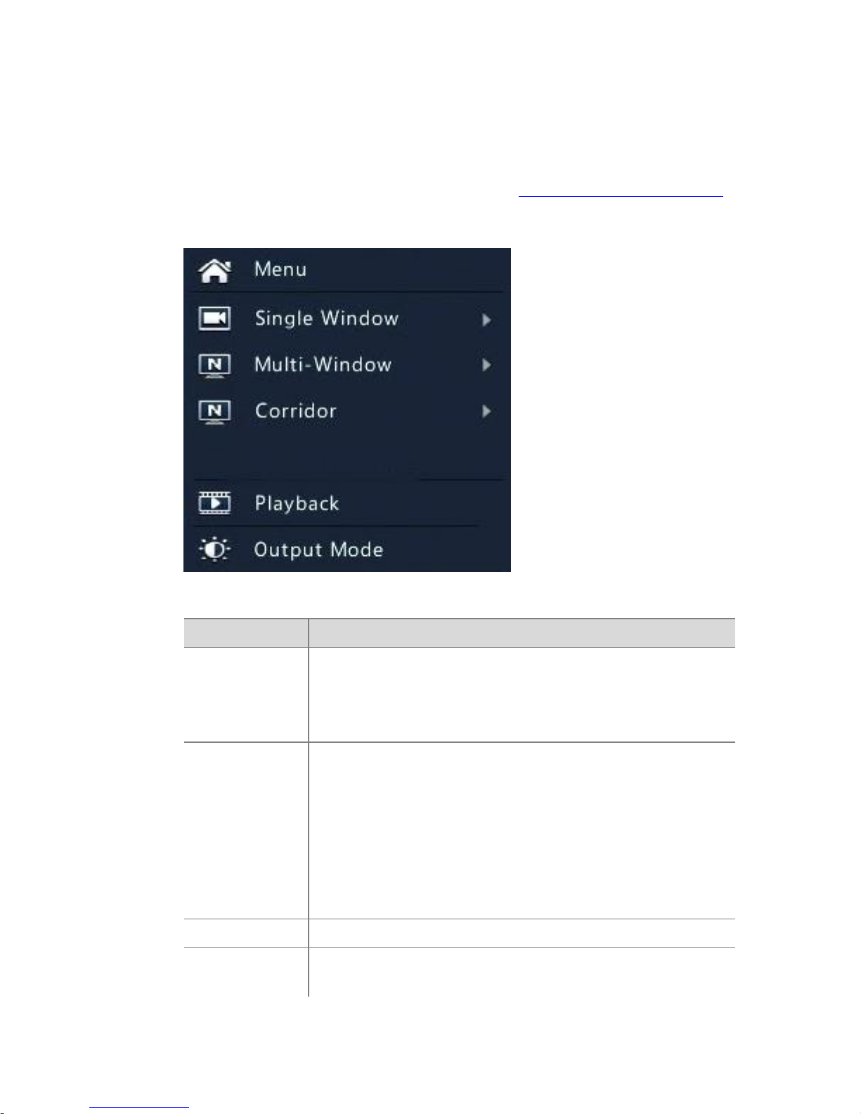
Shortcut Menu
A shortcut menu as shown below appears when you right-click in a
window. Some menu items are described in Shortcut Menu Description.
Table 4-2 Shortcut Menu
Table 4-3 Shortcut Menu Description
Menu
Description
Menu
Access the main menu.
Most of operations described in this manual are performed
start from the main menu; for example, click Camera >
Camera (with Menu > omitted).
Corridor
Choose a corridor mode. Corridor mode can also be set in
the Default Layout drop-down list under System >
Preview.
To display images in corridor mode, the camera must be
installed correctly (rotated 90° clockwise or
counterclockwise), and then use the Image Rotation
parameter under Camera > Image to rotate images
accordingly.
Fisheye Mode
Set mount mode and display mode for fisheye camera.
PTZ Control
Display the PTZ control window for the first PTZ camera in
live view.
Page 21

18
Menu
Description
Playback
Play the current day's recording for the camera linked to
the current window.
Output Mode
Choose a video output mode, including standard, soft,
bright, and vivid.
Sequence Operation
The sequence operation requires you to configure the screen layout,
windows, linked cameras, and the sequence interval.
This example describes how to configure sequence for five cameras
based on a 4-window screen layout.
1. Click 4 Windows on the screen toolbar.
NOTE!
The number of windows that can be displayed may vary with NVR model.
2. Click Start Sequence on the screen toolbar. Sequence starts by
displaying four windows on the first screen and then the fifth on
the second at the set interval.
Page 22
19
NOTE!
⚫ The default sequence interval is eight seconds and can be set under
System > Preview.
⚫ You may drag video to the desired window on the screen.
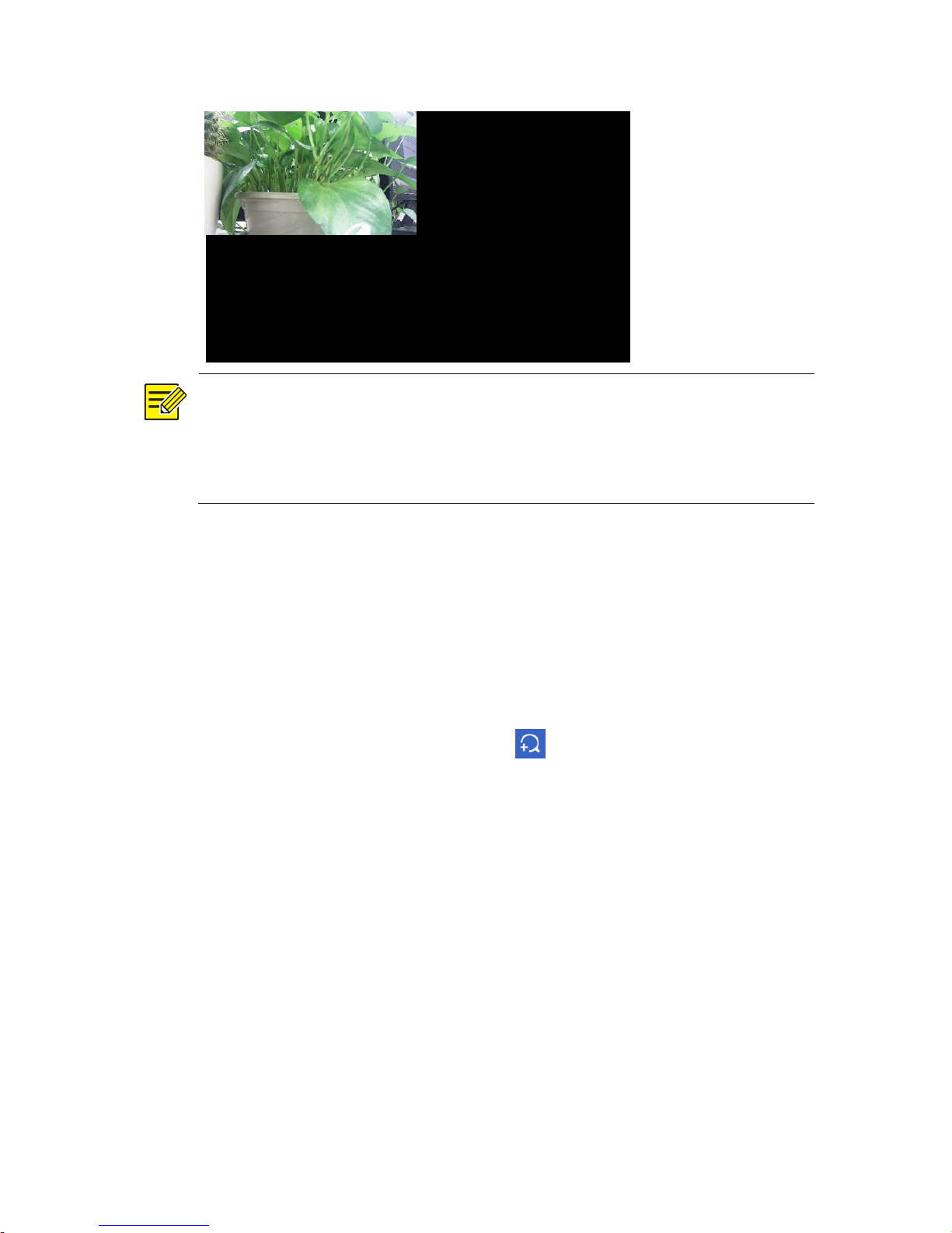
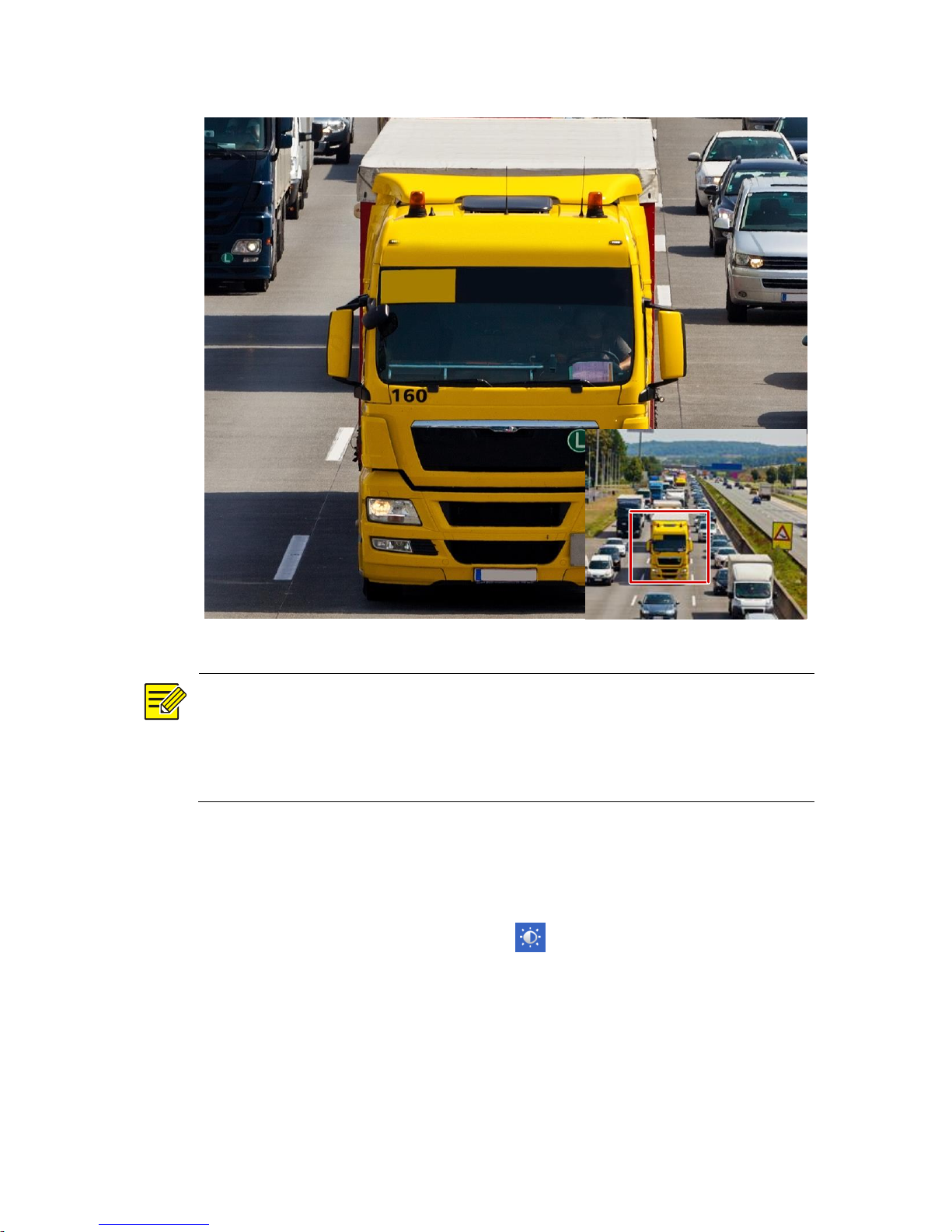
Zoom
Zoom in on an area of images in a window for details.
1. Click the window and then click on the window toolbar.
2. In the small window in the lower right corner, click and drag your
mouse to specify the area to zoom in on. The image in the main
window zooms in. The following shows an example.
Page 23
20
NOTE!
The system adjusts the area automatically according to the window size
and its aspect ratio. Also, the system has specified a minimum size to
ensure zoom effects.
Image Configuration
Adjust image settings to get optimal images from a camera.
1. Click the window and then click on the window toolbar.
2. Select a mode from the drop-down list according to the
surveillance scenario, and then adjust contrast, hue, saturation and
brightness as needed. The settings available may vary with device
model.
Page 24

21
3. Click OK to save the settings and exit.
Preview Configuration
Normally, live view (video) is available after you complete the basic
setup by following the wizard. You can click System > Preview and edit
preview setting as needed, including video output, image resolution,
default layout, and sequence interval. The video output and the number
of windows supported may vary with NVR model.
NOTE!
Pressing and holding the scroll wheel for at least 3 seconds will restore
the default resolution.
Preview Configuration
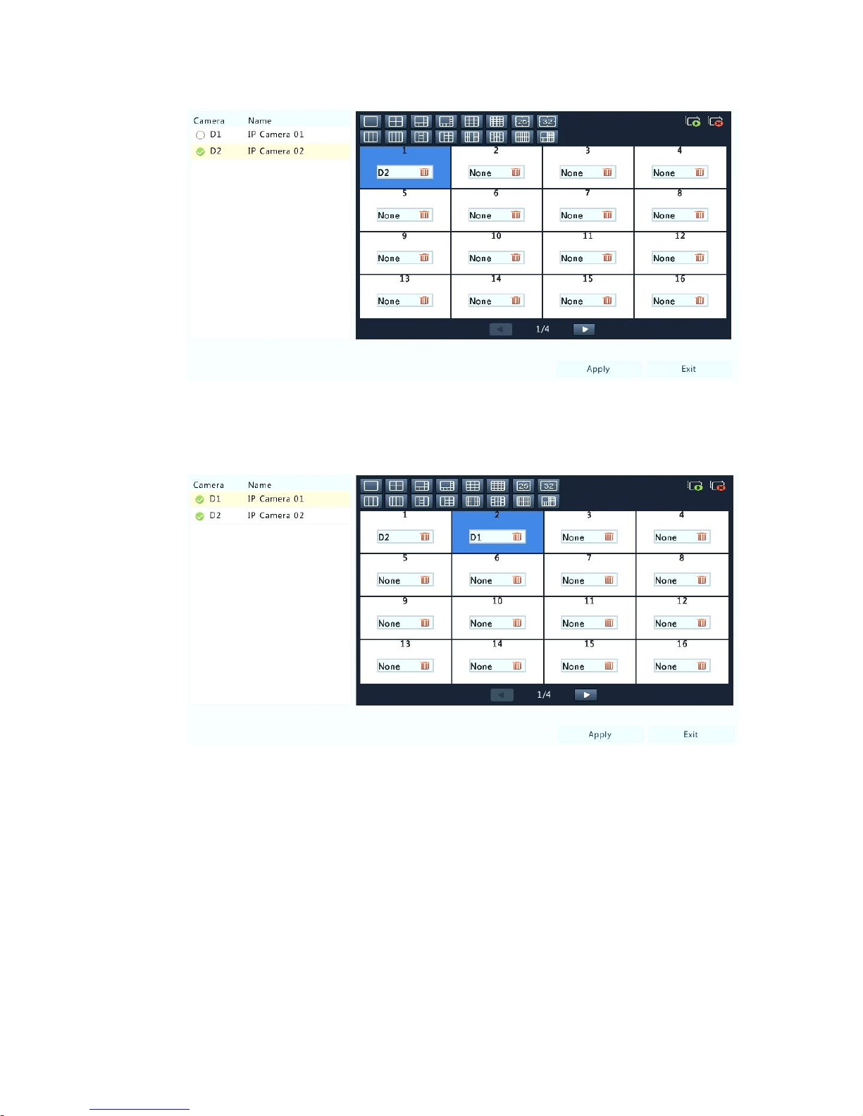
Each preview window (window for short) links to a camera. By default,
window 1 links to camera D1, window 2 links to camera D2, and so on.
You may want to change the link to display live video from a camera in
another specified window. The following example describes how to link
window 1 to camera D2 and link window 2 to camera D1.
Step 1: Click window 1 on the right, and then click D2 under Camera on
the left. Now D2 appears in window 1, and None appears in window 2.
Meanwhile, is cleared for camera D1, meaning D1 is not linked to any
window.
Page 25
22
Step 2: Click window 2 on the right, and then click D1 under Camera on
the left. Now D1 appears in window 2. Click Apply to save the settings.
Advanced Configuration
Click the Advanced tab and then select Sub Stream First so the NVR
uses the sub stream to establish live video from multiple cameras
simultaneously. This function is disabled by default.
1.
Page 26
23
5 Playback
Instant Playback
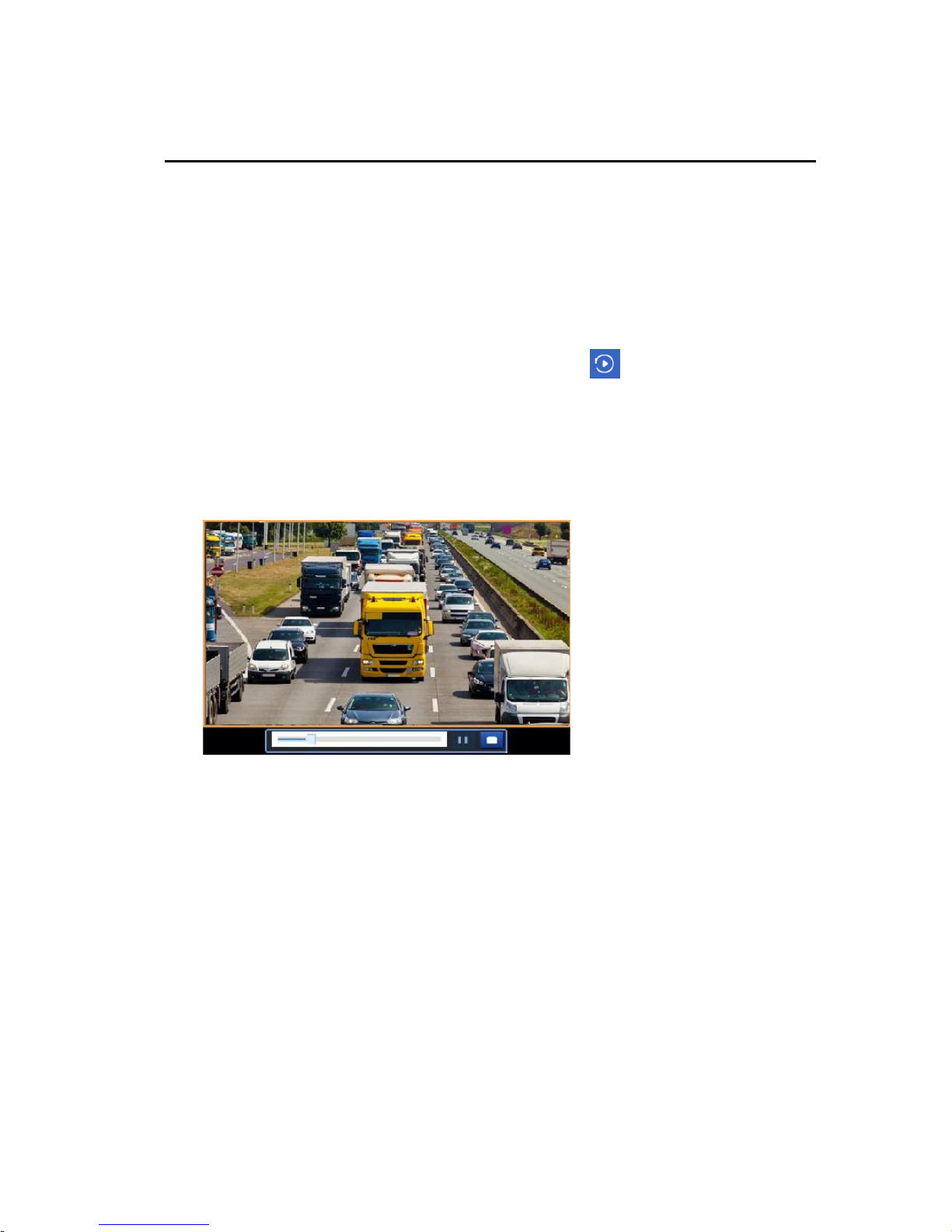
Instant playback plays the video recorded during the last 5 minutes and
30 seconds. If no recording is found, it means there is no recording
during this period.
1. Click the desired window, and then click on the toolbar to start
instant playback.
2. You may drag the slider to control the progress. Pause and resume
as needed.
Page 27
24
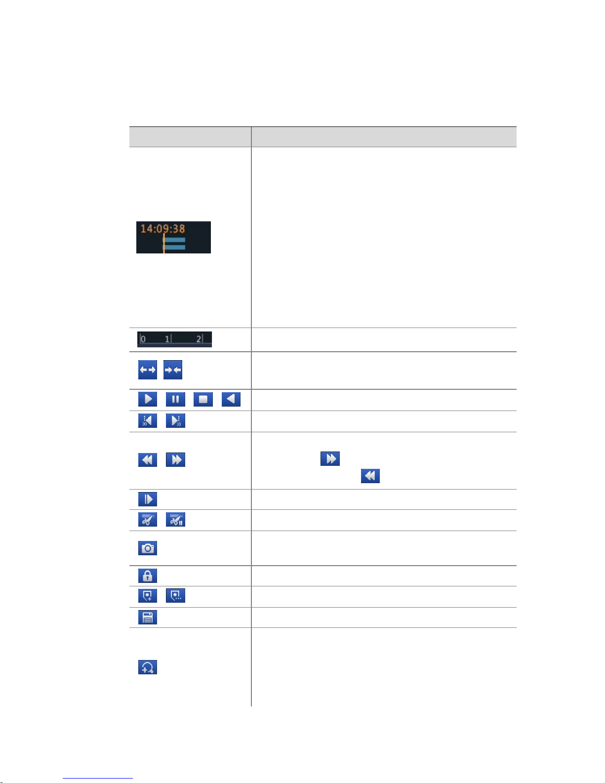
Playback Toolbar
Table 5-1 Playback Toolbar Buttons
Button
Description
Show playback progress.
Note:
⚫ A small window displaying video of the
selected window is displayed as you drag the
slider, helping locate the part of the video
you want to view.
⚫ The first progress bar indicates playback
progress of the video playing in the
highlighted window. The second indicates the
overall playback progress for all the selected
cameras.
Timeline.
/
Zoom in or out on the timeline.
Note: Alternatively, scroll your mouse wheel.
/ / /
Play, pause, stop, and reverse.
/
Rewind or forward 30 seconds.
/
Slow down or speed up.
Note: Click to restore the normal playback
speed after clicking , and vice versa.
Forward by frame.
/
Start or stop clipping video.
Take a snapshot. The window borders will flash
white.
Lock.
/
Add a default or custom tag.
Manage files (clips, snapshots, locked files, tags).
Zoom in on images. For more details, see
Zoom.
Page 28
25
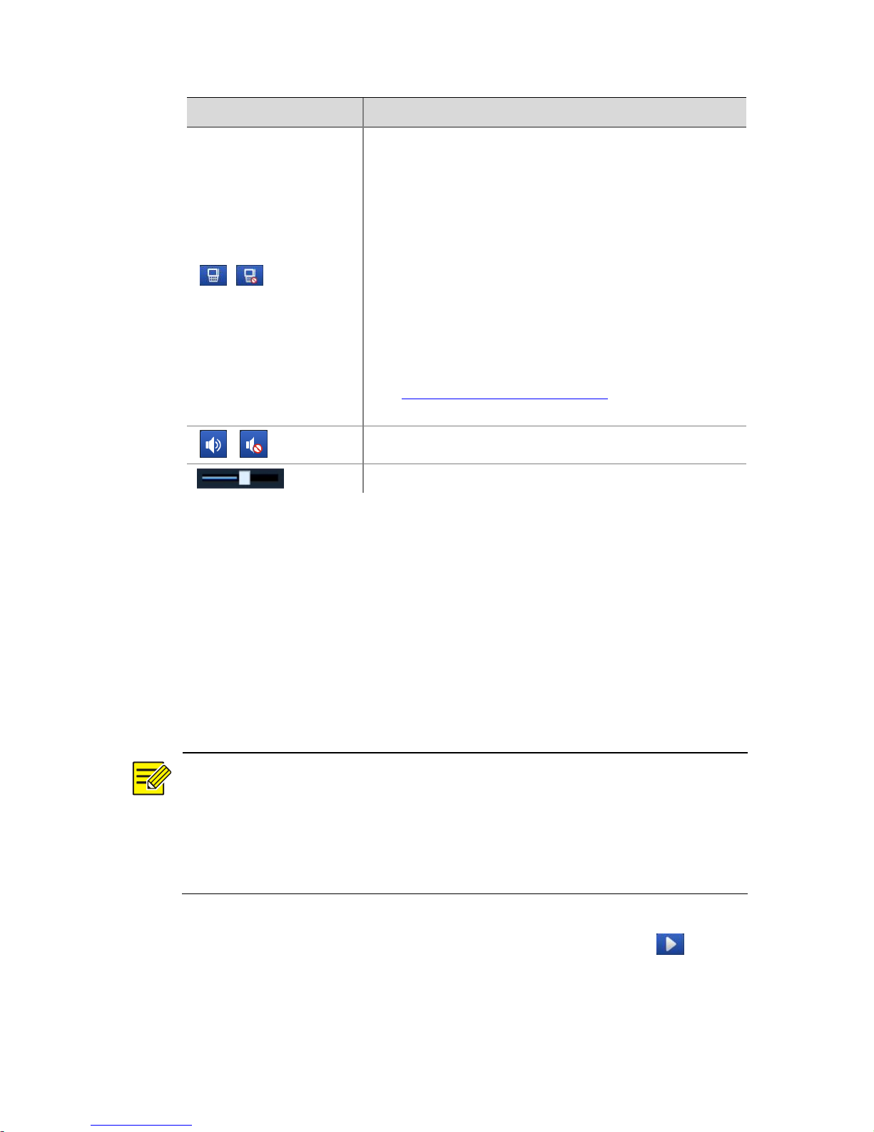
Button
Description
/
Enable/disable POS (available to certain NVR
models).
When enabled, POS OSD appears on the screen,
and some toolbar buttons are deactivated.
These buttons only appear in two playback modes:
playback by camera and data and playback by POS.
POS OSD duration (how long POS OSD appears on
screen) varies with playback mode. For playback by
camera and date, the duration is fixed to 5 seconds.
For playback by POS, the duration is configurable.
See Playback by Camera and Date and Error!
Reference source not found. for more details.
/
Turn off/on audio.
Adjust sound volume for the current window.
Playback by Camera and Date
Use this method to play recordings found by camera and date.
1. Right-click the mouse and then choose Playback.
2. Select the desired camera. By clicking Max. Cameras in the upper
right corner you will select the maximum number of cameras
allowed.
NOTE!
You can select multiple cameras for synchronous playback. Clicking Max.
Camera selects the maximum number of cameras allowed, and clicking
Close All stops playback for all cameras. The performance varies with
NVR model.
3. Select the desired date on the calendar and then click to start
playback. Double-clicking the date will start playback directly.
Page 29
26
NOTE!
⚫ The calendar uses different flags to indicate different recording
types. No flag means no recording. The blue flag means normal
recording. The red flag means event-triggered recording.
⚫ In the drop-down list right to playback mode: High Definition means
video recorded with the main or sub stream; Standard Definition
means video recorded with the third stream.
Playback in Corridor Mode
Play recordings in corridor mode in multiple windows.
1. In the playback window, select Corridor from the drop-down list in
the upper left corner.
2. Select cameras and then double-click the desired date to start
playback.
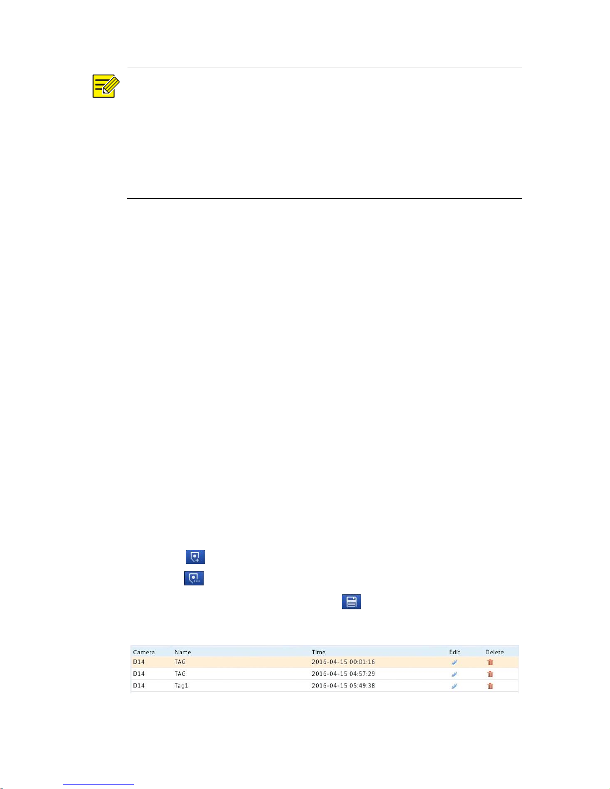
Playback by Tag
Add tags named with keywords such as event name and location to a
recording and use tags to quickly locate the part of the video you need
during playback.
Adding a Tag
1. Right-click and then click choose Playback.
2. Click to add a default tag named TAG. To add a custom tag,
click and then set the tag name, for example, tag1.
3. To manage the added tags, click , and then rename or delete
tags as needed.
Page 30

27
Playback by Tag
1. In the playback window, select Tag from the drop-down list in the
upper left corner.
2. Select cameras, set the time period, enter keywords, and then click
Search. Search results, if there are any, are displayed with names
of cameras and tags.
3. Click for the desired tag to start playback. You may use the Start
Before and Stop After drop-down lists to set when the tagged
video starts and ends.
Playback by Event
Specify an event type and search for and play videos recorded for one or
more cameras during a specified time period.
1. In the playback window, select Event from the drop-down list in
the upper left corner.
2. Select the desired event type, for example, motion.
3. Select the desired camera, set the time period, and then click
Search.
4. Click for the desired recording to start playback.
Playback by Smart Search
This function provides an efficient way to review recordings containing
smart search results such as detected motions. In smart playback mode,
the system analyzes recordings for smart search results. If such results
are detected, the progress bar is highlighted in green, and the video
plays at the normal speed, allowing you enough time to catch details;
otherwise, the video plays at 16x speed to save time.
Page 31

28
1. In the playback window, select Smart from the drop-down list in
the upper left corner.
2. Click for the desired camera to start smart playback.
3. Click . The smart search window is displayed. By default, the full
screen is the smart search area. To clear all, click ; to restore the
full-screen search area, click .
4. Set smart search rules, including detection area and sensitivity.
5. Click to start search. To quit, click .
Playback by External File
Use this function to play recordings stored in an external storage device,
for example, a USB drive or a portable USB hard drive.
1. In the playback window, select External File from the drop-down
list in the upper left corner.
2. Click Refresh and then wait for the NVR to read the external
storage device.
3. Select the desired recording file and then click to start playback.
Playback by Image
Specify an image type (for example, Normal or Motion) to search for and
play images from one or more cameras during a specified time period.
1. In the playback window, select Image from the drop-down list in
the upper left corner.
2. Select a type from the Type drop-down list in the upper right
corner.
3. Select the desired camera(s), set the desired time period, and then
click Search.
4. Click the desired file to start playback.
Page 32
29
File Management
File management allows you to manage video clips, tags, snapshots
taken during playback, and lock or unlock files.
1. Take snapshot during playback.
a. Click in the playback window to take a snapshot of the
desired image.
b. Click and then click the Playback Image tab to view the
snapshot.
c. Select the desired image file(s) and then click Backup to save
them to the storage device.
NOTE!
The image resolution depends on the resolution from the output
interface and the number of windows displayed when the snapshot is
taken.
2. Lock files.
Use this function to lock a recording file so it will not be overwritten.
a. Click for the recording you want to lock in the playback
window.
b. Click and then click the Locked File tab to view the locked
file. To unlock a file, click , and the icon changes to . To back up
a file, select the file and then click Backup.
Page 33

30
6 Backup
Recording Backup
Backup, also known as recording backup, is the process of querying
video stored on a hard disk of the NVR and then saving to a USB storage
device or a DVD-R disc as a file.
Recording backup has the following conditions:
⚫ Back up using a USB storage device: format the partition in FAT32
or NTFS format; connect the storage device correctly to the NVR.
⚫ Back up using a disc: use a GP65NB60 DVD burner. Make sure the
DVD-R disc is empty, and the burner is correctly connected to the
NVR.
⚫ Permission is required.
⚫ The recording to back up is stored on a hard disk of the NVR.
NOTE!
⚫ The default file format is .mp4 when you back up recordings to a
USB storage device.
⚫ When backing up using a disc, recordings are saved as .TS files only.
Normal Backup
1. Click Backup > Recording. All cameras are selected by default.
2. Set search conditions and then click Search. Search results are
displayed.
NOTE!
You can lock/unlock and play recording files in this window.
3. Select the desired recording(s) and then click Backup.
Page 34
31
4. Select a partition.
⚫ Back up to USB storage device
Set the destination in the USB storage device and then click Backup. The
recording(s) will be saved to the specified directory.
NOTE!
⚫ You may want to create a new folder for the recording(s) by clicking
New Folder.
⚫ If the connected storage device has a capacity that is greater than
2T, clicking Format will format the device to NTFS file system; if the
capacity is 2T or less, the device will be formatted to FAT32 or NTFS.
Only certain devices can format a storage device that has a greater
capacity than 2T.
⚫ A progress bar (e.g., Exporting X/Y) is displayed to indicate the
progress, where X indicates the current number being backed up,
and Y indicates the total number of recordings. To cancel the
operation, click Cancel.
⚫ A backup file is named in this format: camera name-recording start
time.file extension. For example, Ch9-20150630183546.mp4.
⚫ Back up to a DVD-R disc
Set the destination and then click Backup. The recording(s) will be saved
to the specified directory.
NOTE!
⚫ Before you start burning, check that the video to back up was not
compressed using Smart Encoding.
⚫ Clicking Cancel before burning is finished will cause the disc
unusable.
⚫ When burning is finished, wait for the drive to eject itself. Do not
eject the drive manually.
⚫ The NVR does not support playback of recordings saved on a disc.
Page 35

32
Video Clip Backup
A recording can be clipped and saved to a USB storage device.
1. Open the playback window. For the detailed steps, see Playback.
2. After playback starts, click and on the playback toolbar to
clip videos.
3. Click and then click the Video Clip tab to view video clips.
4. Select the desired video clip(s) and then click Backup.
5. Select a destination in the USB storage device and then click
Backup. The selected video clips are saved to the specified
directory.
Image Backup
The default format of image backup is JPG.
1. Click Backup > Image.
2. Set search conditions and then click Search. Search results are
displayed.
NOTE!
The image resolution depends on the resolution from the output
interface and the number of windows displayed when the snapshot is
taken.
3. Select the desired file(s) and then click Backup.
4. Select a destination in the USB storage device and then click
Backup. The selected files are saved to the specified directory.
Page 36
33
7 System Configuration
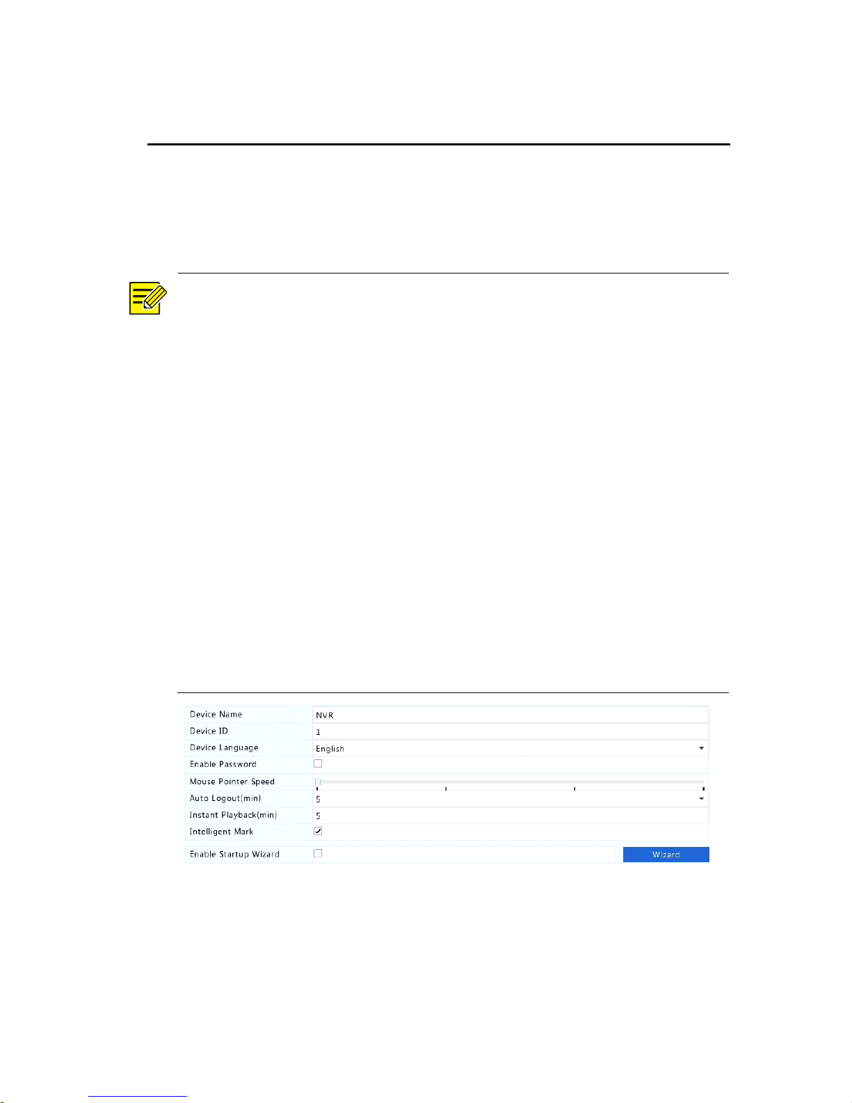
Basic Configuration
1. Click System > Basic.
2. Configure the parameters.
NOTE!
⚫ Only admin can set Enable Password.
⚫ If Enable Password is not selected, no password is required for local
login at system startup. However, a username and password are still
required when you log in after a logout.
⚫ Some NVR models support Intelligent Mark. When the NVR and IP
camera are both enabled, the latest areas/lines or VCA data
configured for face detection, intrusion detection, and cross line
detection will be displayed on the Preview, Behavior and Alarm
windows in real time.
⚫ Intelligent mark is displayed on the screen as areas/lines in different
colors. Yellow means areas/lines configured for face detection,
intrusion detection, and cross line detection; green means VCA data
has changed but not triggered rules; red means rules are triggered
in the configured area (rules are configured for VCA alarms ), and
VCA alarm has occurred.
⚫ You may also set startup Wizard here by clicking Wizard.
3. Click Apply to save the settings.
Page 37
34
Time Configuration
Time
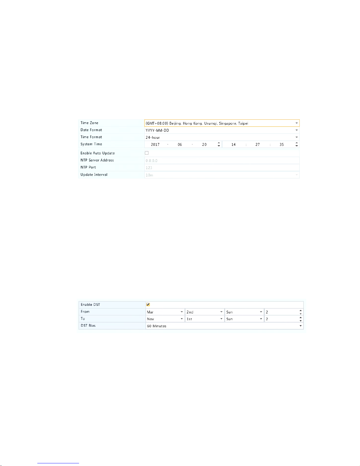
1. Click System > Time > Time.
2. Select the correct time zone, and then set date and time formats
and the system time. The following shows an example.
3. To use Network Time Protocol (NTP), enable auto update, set the
address and port number of the NTP server, and the update
interval.
4. Click Apply to save the settings.
DST
1. Click System > Time > DST.
2. Enable DST by selecting the check box, and then set the start time,
end time, and DST bias correctly. The following shows an example.
3. Click Apply to save the settings.
Time Synchronization
Use this function to synchronize camera time with the NVR. Time sync is
enabled by default, and cameras will synchronize time with the NVR
after getting online, and then synchronize once every 30 minutes.
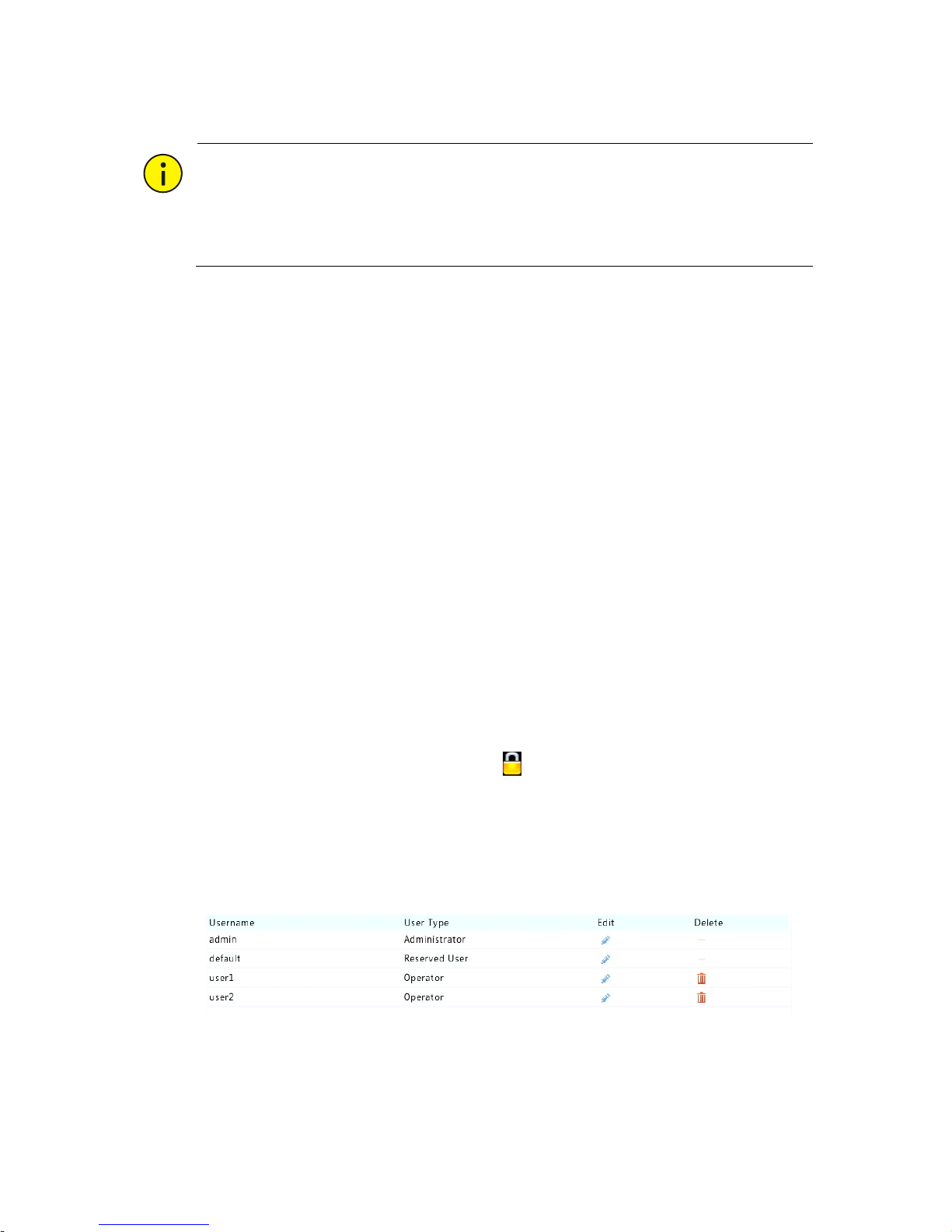
1. Click System > Time > Time Sync.
Page 38
35
2. Select Sync Camera Time and then click Apply.
CAUTION!
Use this function with caution if you have more than one NVR on the
network. An IP camera synchronizing time with multiple NVRs at the
same time will cause chaotic recordings.
User Configuration
Add, delete users or edit user permissions. Only admin can perform
these operations.
A user type is a set of permissions in the system. When a user type is
assigned to a user, this user has all the permissions specified for the user
type.
There are four user types in the system:
⚫ Admin: Default super administrator in the system, has full system
access. Its initial password is 123456.
⚫ Default: Default user reserved in the system, cannot be created or
deleted, and only has access to live view and two-way audio. If the
default user is denied access, the corresponding channel is locked
when no user is logged in, and appears in the window.
⚫ Operator: Has basic permissions and access to cameras.
⚫ Guest: Only has access to cameras by default.
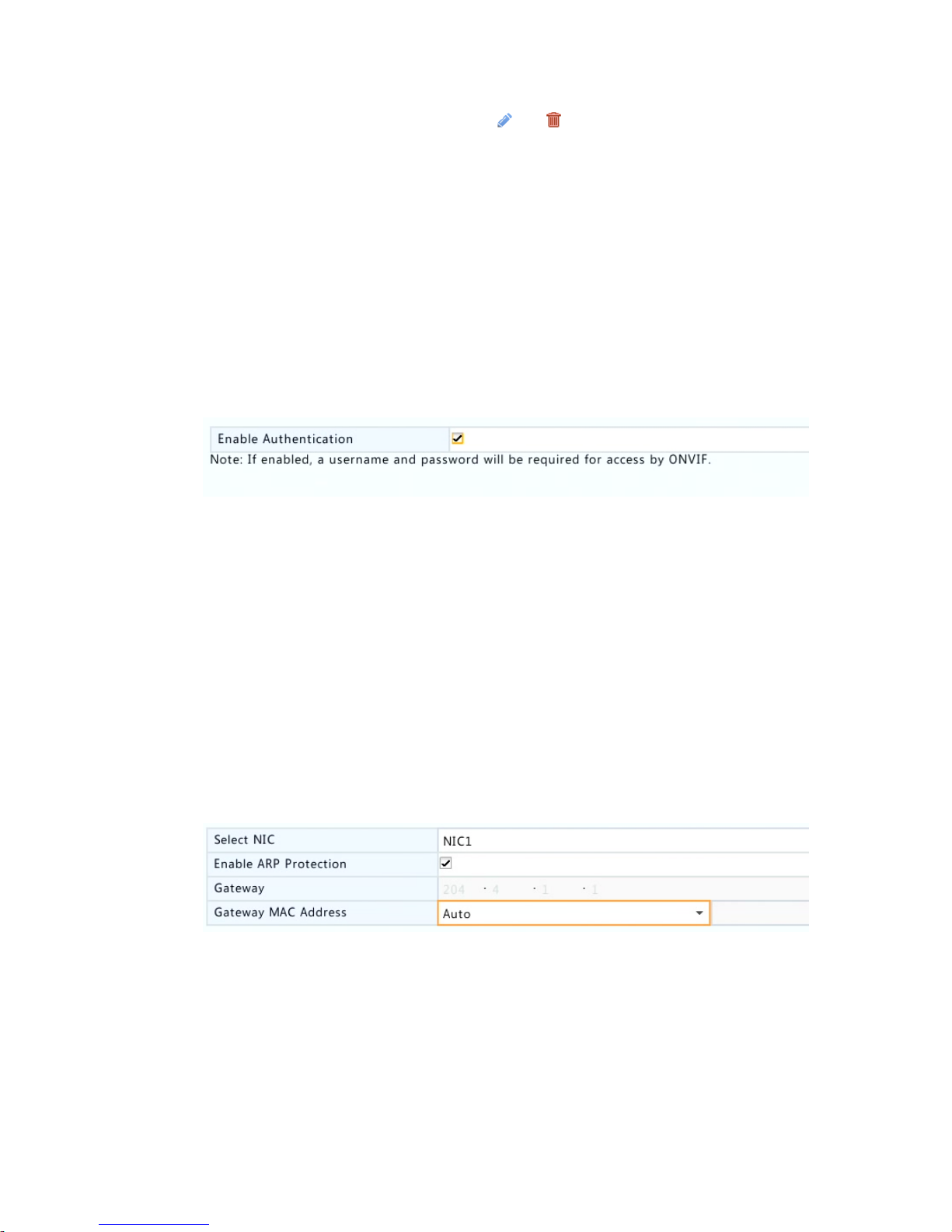
1. Click System > User.
2. To add a user, click Add, and then set the username, user type,
password and permissions as needed. Click OK to save the settings.
Page 39
36
3. To edit or delete a user, click or as needed. If you change the
password for a user, the new password takes effect at the user's
next login.
ONVIF Authentication
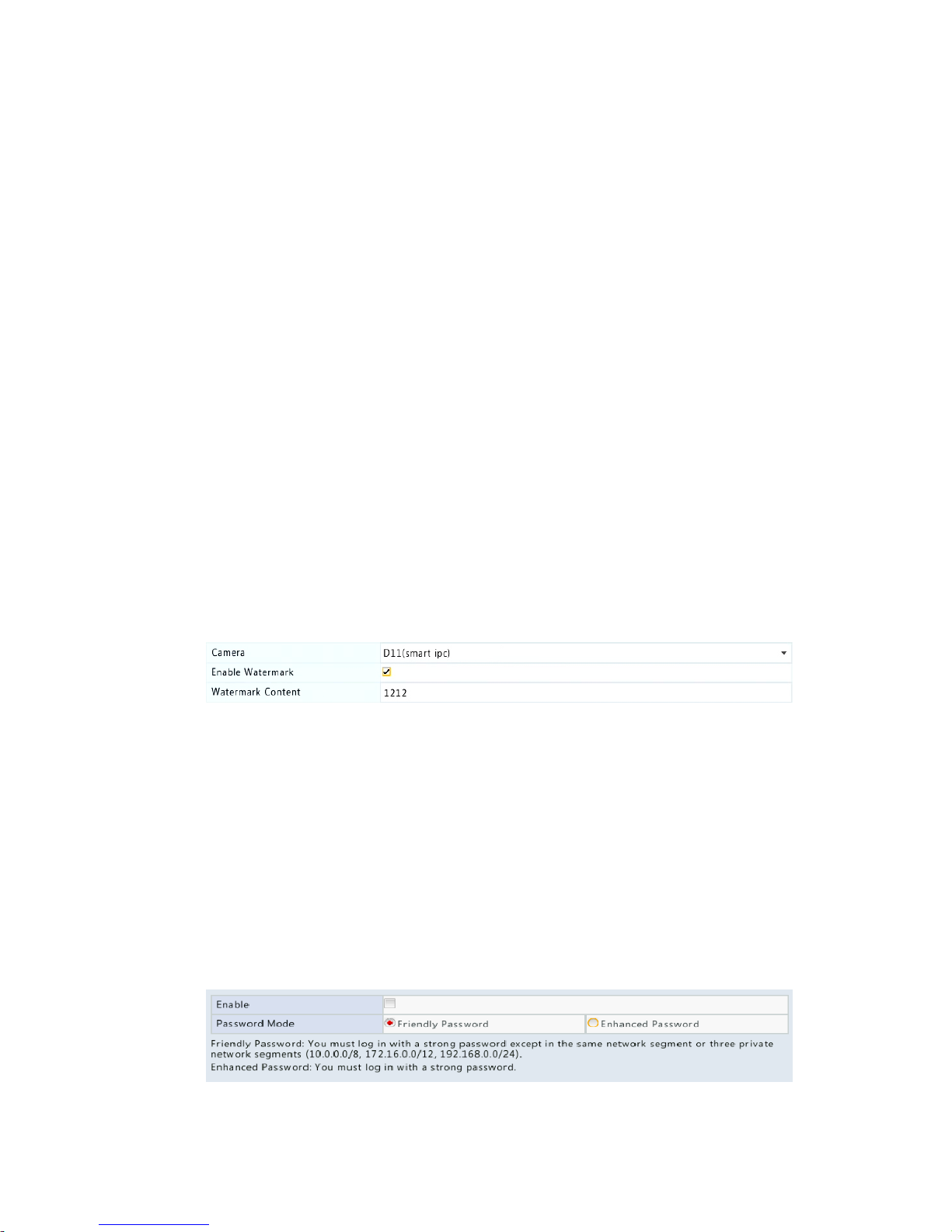
Enable ONVIF authentication under System > Security > ONVIF Auth so
a username and password will be required for ONVIF-based device
access.
Select the check box and then click Apply.
ARP Protection
ARP protocol is used to associate an IP address to a hardware MAC
address. ARP attacks mainly occur on LAN, in which attackers use forged
IP and MAC addresses. APR protection prevents this kind of attacks by
verifying the gateway's MAC address in all access requests.
Note that changing the NIC working mode will disable ARP protection
automatically.
1. Click System > Security > ARP Protection.
2. Select the desired NIC and then select Enable ARP Protection.
3. Obtain the gateway's MAC address automatically, or select Custom
and input the MAC address.
4. Click Apply to save the settings.
Page 40
37
802.1x
802.1x is a port-based network access control protocol mainly used to
solve authentication and security issues on LAN.
Only certain NVR models support this function. Note that changing the
NIC working mode will disable 802.1x automatically.
1. Click System > Security > 802.1x.
2. Select the desired NIC and select the check box to enable 802.1x.
3. Select the EAPOL version, and then enter the username and
password of the authentication server.
4. Click Apply to save the settings.
Video Watermark
Encrypt custom information in videos to prevent unauthorized
alteration.
1. Click System > Security.
2. Select the desired camera and then select Enable Watermark.
3. Enter watermark content.
4. Click Apply to save the settings.
Secure Password
Secure password specifies the permission of strong or weak password in
different modes: friendly password and enhanced password.
1. Click System > Security.
Page 41

38
2. Once Enable is selected, the option will be hidden, and by default
friendly password is enabled. You may enable Enhanced Password
as needed.
⚫ Friendly Password
If this option is selected, a strong password must be used except when
login from the same network segment or one of the three private
network segments (10.0.0.0/8, 172.16.0.0/12, 192.168.0.0/24).
⚫ Enhanced Password
If this option is selected, a prompt for a strong password will appear
when a weak password is detected. Also, only strong passwords are
allowed for new users.
NOTE!
Only admin can configure secure password.
3. Click Apply to save the settings.
8 Channel Configuration
Channel Management
This chapter describes how to add and manage IP devices in your NVR.
The IP devices mentioned in this manual mainly refer to IP camera (or
network camera); sometimes they can also be Digital Video Server
(DVS). Before you start, make sure the IP devices are connected to your
NVR via network.
Page 42
39
CAUTION!
An IP device should be connected to one NVR only. An IP device
managed by multiple NVRs may cause unwanted issues.
Adding an IP Device
This section provides multiple options to add an IP device. Some options
are only applicable to certain NVR models. Choose one as appropriate.
Option 1
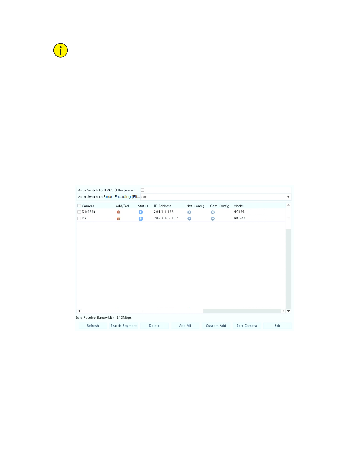
1. Click Camera > Camera > Camera. The system automatically
searches for IP devices and lists the discovered.
Page 43

40
NOTE!
⚫ under Status means an IP device is added successfully, and you
may click to view live video from the IP device. means the IP
device is offline, and you may view the cause by resting the mouse
pointer on the .
⚫ The idle bandwidth is displayed to indicate current bandwidth
available for receiving streams. For more details, see Error!
Reference source not found..
2. (Optional) To search a specified network segment, click Search and
then set the address range.
3. Click for the IP device to add. Or, you may also
⚫ Click One-click Add to add all the discovered IP devices allowed
(depending on channels supported by the NVR).
⚫ Click Custom Add. In the window displayed, enter the IP address
and complete other settings, and then click Add. You may also click
Search and add discovered cameras in the list.
NOTE!
For a Digital Video Server (DVS), a window appears when you click Add,
and you need to select channels to add the connected cameras.
Option 2
This option is not applicable to NVRs with PoE ports or switching ports.
1. Click in a window.
Page 44

41
2. Select the desired IP device and then click Add.
Option 3
This option is only applicable to NVRs with PoE ports or switching ports.
Connect an IP camera to a PoE port or a switching port with a network
cable. The connected camera will be added to the NVR automatically.
Check status under Camera > Camera > Camera. means live video
from the camera is available. Click to view live video.
If the camera is connected via a network switch, click under Edit. In
the window displayed, set Add Mode to Manual and then complete the
settings correctly.
NOTE!
appears under Status if the power output from a PoE port is below or
above the rated power of the connected camera.
Option 4
Use this option to add an IP device that is connected to a different
router, for example, when the NVR and the IP device are connected
across the Internet.
Page 45
42
NOTE!
First you need to enable port mapping at Setup > Port > Port Mapping
on the IP device's Web interface.
1. Click Camera > Camera, click Custom Add.
2. Choose an option:
⚫ By IP
a. On the IP device's Web interface, go to Setup > Port > Port
Mapping, find the external IP (public IP) and external port number.
b. On the NVR: Select a protocol, enter the above-mentioned IP
address and port number, enter the username and password.
c. Click OK.
⚫ By EZDDNS
a. On the IP device's Web interface, go to Setup > Network >
DDNS, enable DDNS, select EZDDNS, set a domain name and get
the server address.
NOTE!
⚫ After setting the domain name, check that you can use the device
address to access the IP device's Web interface.
⚫ Make sure the EZDDNS server and the NVR are connected (ping the
EZDDNS server from the NVR).
b. On the NVR: Select a protocol, enter the above-mentioned
server address, domain name, username and password.
c. Click OK.
⚫ By a domain name
a. On the IP device's Web interface, go to Setup > Network >
DDNS, enable DDNS, select DynDNS or NO-IP, enter the domain
name that you have signed up on the DNS website, enter the
username and password, and then click Save.
Page 46
43
b. On the NVR: Select a protocol, enter the domain name
mentioned above, enter the username and password. The port is
the external port of the IP device.
c. Click OK.
NOTE!
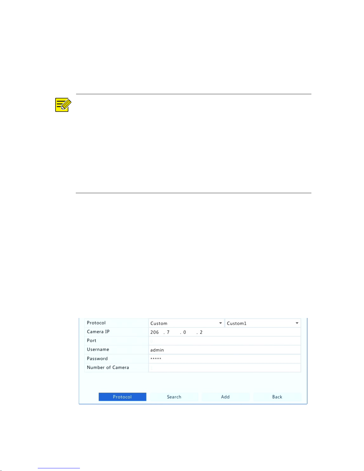
⚫ If Custom is selected for Protocol, the port is the mapped external
RTSP port of the IP device.
⚫ Do not add an IP device to an NVR using different methods (e.g., IP
and EZDDNS) at the same time.
⚫ When an IP device is added by EZDDNS, domain name (NO-IP or
DynDNS), or IP (public IP+public port) and it is not connected to the
same router as the NVR, alarm is configurable, but alarm push is not
available.
Option 5
Use this option only when the IP device to add supports the standard
RTSP, and all you need from the IP device are just view live and playback.
IP devices added in this way cannot be configured from the NVR.
1. Click Camera > Camera.
2. Click Custom Add.
3. Click to select a camera in the list, select Custom from the Protocol
drop-down list, and then click the Protocol button.
Page 47
44
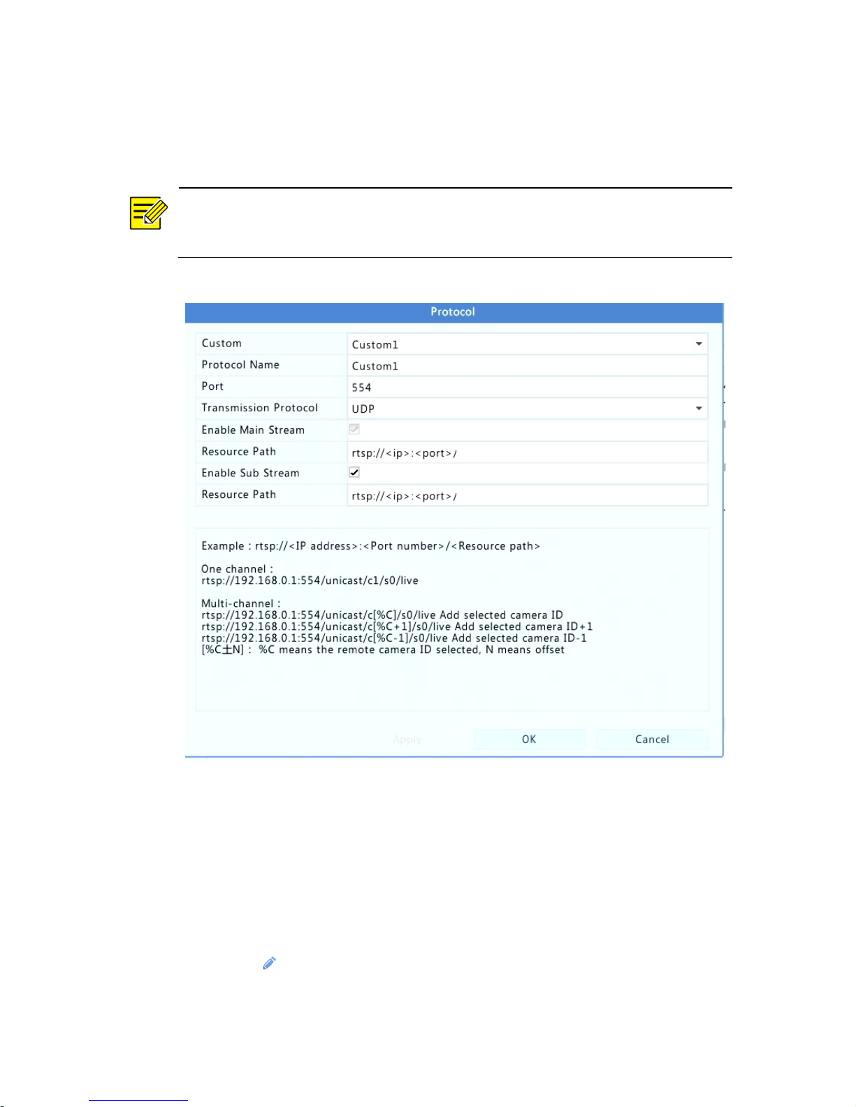
4. In the Protocol window, name the protocol, enter the RTSP port
number, select a transmission protocol, input the resource paths,
and then click Apply.
NOTE!
Contact the camera manufacturer for resource paths.
5. Edit settings in the Add/Modify window as needed, including the IP
address, username and password, and then click Add. Check status
in the camera list.
Managing an IP Device
Manage IP devices under Camera > Camera > Camera.
⚫ Click to edit settings including the protocol, IP address, port
number, username and password. The Camera IP field displays the
Page 48

45
IP address that the current channel links to, and you may change
the address so the channel links to another device. The username
and password must be consistent with that of the IP camera.
⚫ Click to delete an IP device, or select multiple IP devices and
then click Delete. Channels corresponding to PoE ports or switching
ports cannot be deleted.
⚫ Click to change the IP address of an IP camera and the default
gateway. A DVS' IP address cannot be editted from the NVR.
means this function is not available.
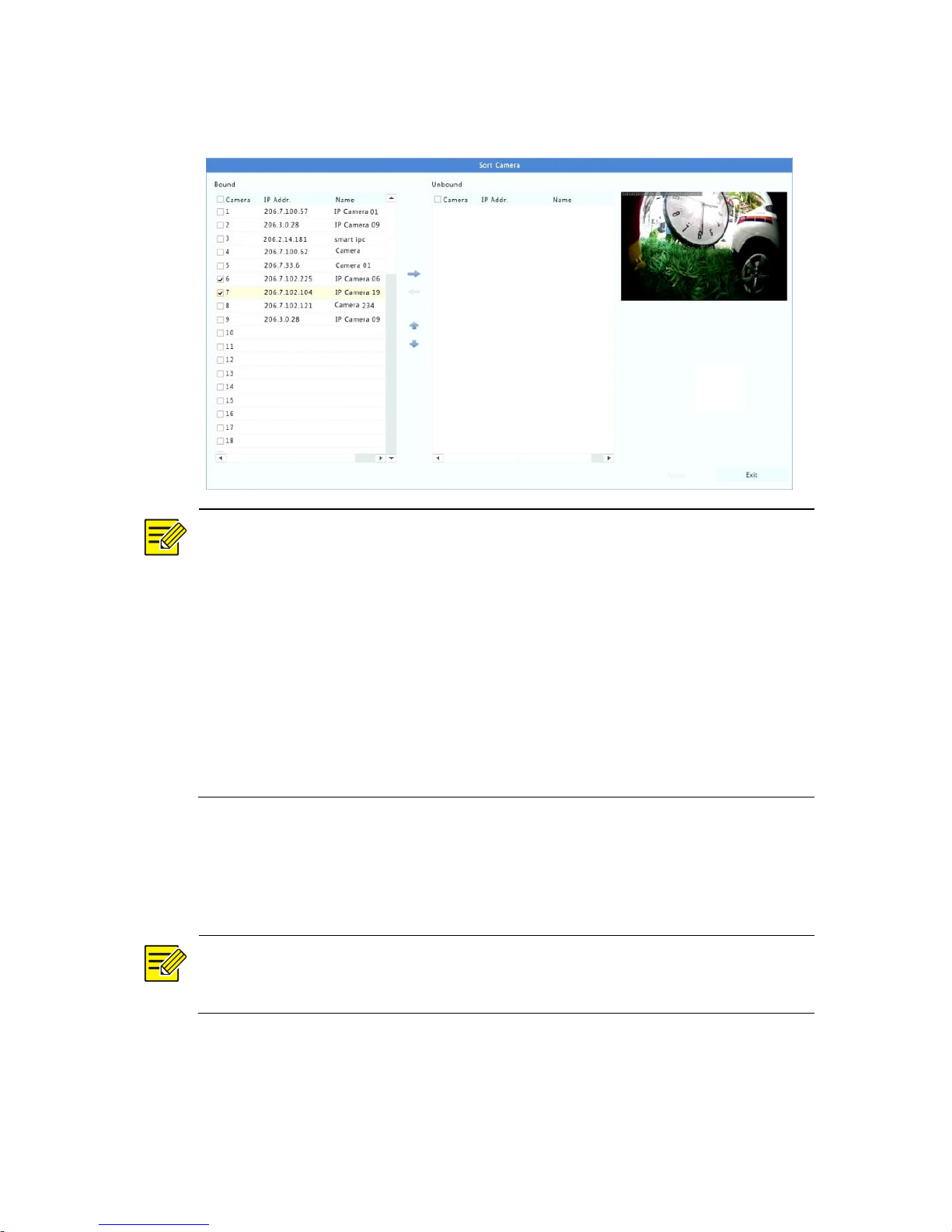
Sort Cameras
Sort cameras to display in the desired order.
NOTE!
⚫ This function is unavailable to NVRs with PoE ports or switching
ports.
⚫ This chapter describes how to sort cameras on an NVR with more
than 32 channels. For NVRs with 32 channels or less, you can sort
cameras by dragging the mouse.
For example, to switch channel 1 with channel 4, click Sort Camera, and
then follow the steps below:
1. In the left list, select the check box for channel 1, and then click
. Channel 1 now appears in the right list. Perform the same
operations to channel 4.
2. In the right list, select channel 4 and then click . Now channel
4 appears at the previous line of channel 1 in the list. Perform the
same operations to channel 1, so channel 1 appears at the previous
line of channel 4 in the list.
Page 49
46
3. Click Apply to save the setting, and then click Yes.
NOTE!
⚫ To move a channel left or right, select the check box first;
otherwise, the buttons are grayed.
⚫ To move a channel up or down, click the channel first; otherwise,
the buttons are grayed.
⚫ A channel will be inserted to the first blank line in the left list unless
you have specified another line in the list by selecting the
corresponding check box.
⚫ Save cannot be clicked when the right list is not empty. You need to
clear the list first.
Fisheye Configuration
Only certain NVR models can dewarp images from fisheye cameras.
NOTE!
Fisheye configuration is supported only by certain fisheye cameras.
Configuration
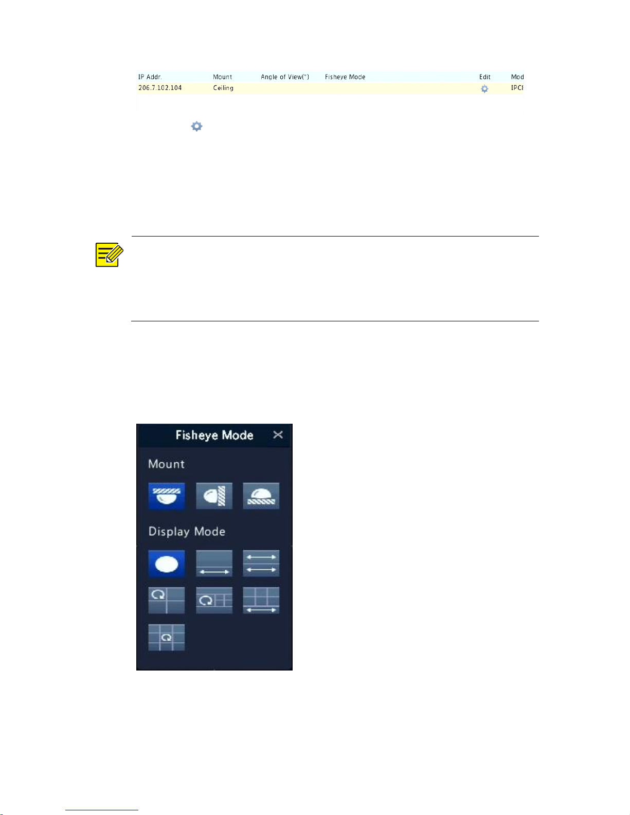
1. Click Camera > Camera > Fisheye.
Page 50
47
2. Click under Edit. The Fisheye window appears.
3. Select a correct mounting mode and complete other settings
accordingly.
4. Click OK.
Dewarping
NOTE!
Dewarping is available in live view and playback (in normal and corridor
playback modes). The operations are similar. The following describes
dewarping in live view.
Right-click a fisheye camera and then select Fisheye Mode from the
shortcut menu. The figure below appears. Set mounting mode and
display mode.
Three mounting modes are available: ceiling, wall, desktop. Ceiling and
desktop mounting modes use the same dewarping method.
Page 51
48
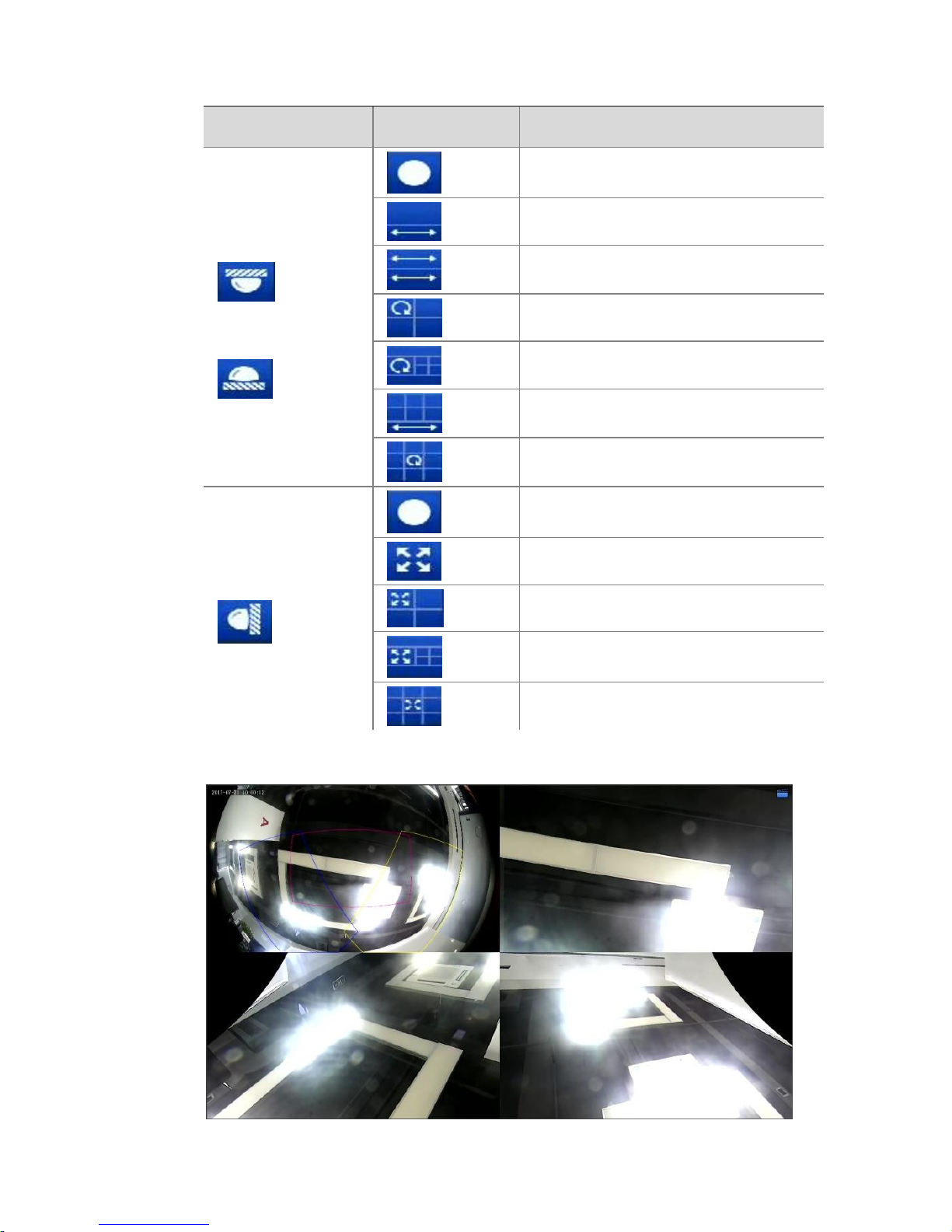
Mounting Mode
Display Mode
Description
Ceiling mount
Desktop mount
Original Image
360°Panoramic+1PTZ
180°Panoramic
Fisheye+3PTZ
Fisheye+4PTZ
360°Panoramic+6PTZ
Fisheye+8PTZ
Wall mount
Original Image
Panoramic
Panoramic+3PTZ
Panoramic+4PTZ
Panoramic+8PTZ
Operations: Take Ceiling Mount and Fisheye+3PTZ as an example:
Page 52

49
On a PTZ image, drag the mouse to rotate the image or use the scroll
wheel to zoom in or out. A box appears on the fisheye image as the
image rotates, and as you drag the box or move the scroll wheel on the
fisheye image, the corresponding PTZ image rotates or zooms in or out
as well.
Advanced Functions
Upgrade connected IP cameras or restore factory default settings for
cameras under Camera > Camera > Advanced.
Click Check to see if the version of the connected IP camera is up to
date. You may upgrade cameras by cloud ( ) or by disk ( ) one by
one, or select multiple cameras and then click Upgrade by Cloud or By
Disk to upgrade cameras in batches.
OSD Configuration
On Screen Display (OSD) are characters displayed with video images on
the screen, for example, camera name, date and time.
1. Click Camera > OSD; or click on the preview window toolbar.
2. Select the desired camera and then enter a camera name you want
to display on the screen.
3. Select date and time formats. Choose to display time, camera
name and people counting result as needed.
4. Set font size and color as needed.
5. Drag the OSD to the desired position in the preview window on the
left.
6. (Optional) Click Copy to apply the same settings to other cameras.
7. Click Apply to save the settings.
Page 53
50
Privacy Mask Configuration
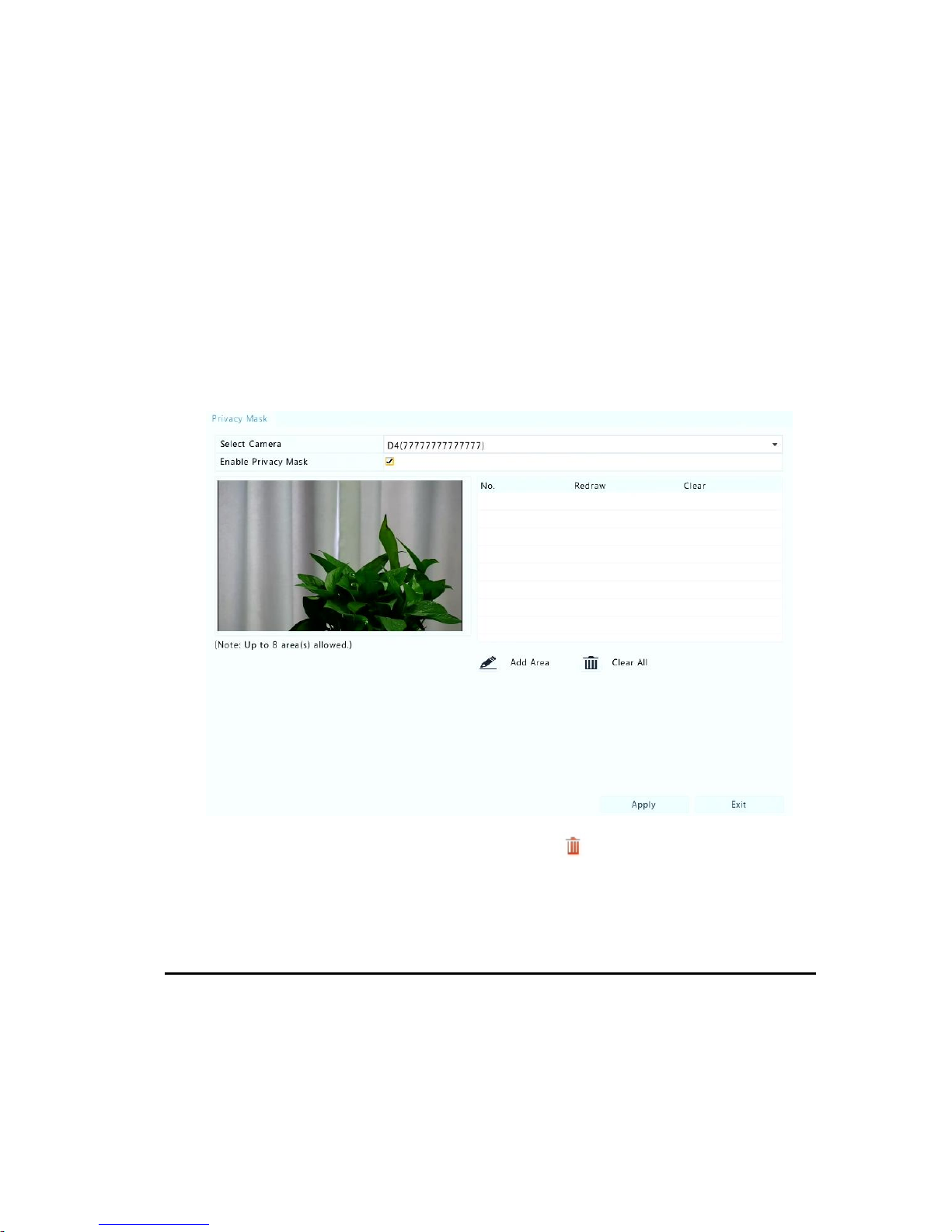
A privacy mask is an area of solid color covering certain parts of the
monitored area. Privacy mask protects specified areas of images from
being viewed and recorded. Multiple mask areas are allowed.
1. Click Camera > Privacy Mask.
2. Select the desired camera, select Enable Privacy Mask, click Add
Area and then use the mouse to specify areas to mask. Up to four
areas are allowed. The areas are differentiated by different colors.
3. (Optional) To clear a mask area, click .
Click Apply to save the settings.
9 System Maintenance
System Information
Click Maintain > System Info to view the basic NVR information for
maintenance purpose.
Page 54
51
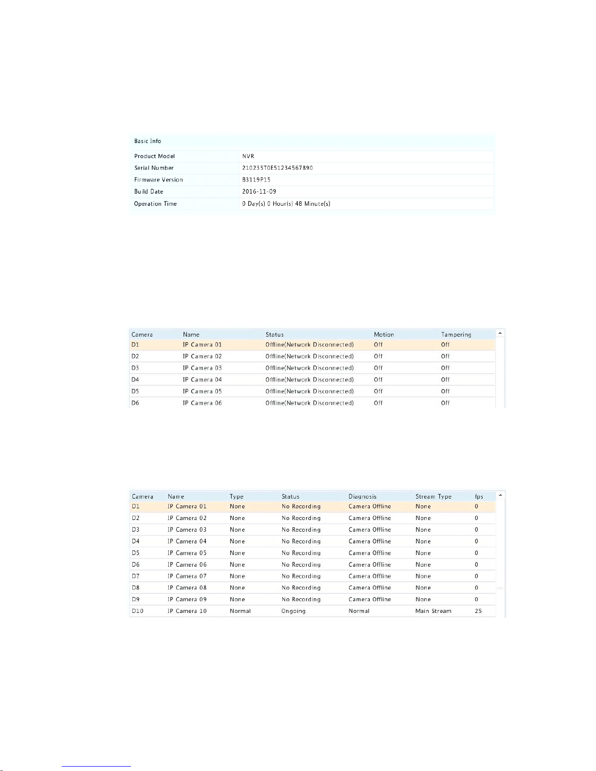
System Info
View the basic information such as the device model, serial number,
firmware version, build date and operation time.
Camera status
Click the Camera tab to view camera status (online or offline with
possible offline cause) and status of alarm functions such as motion
detecion, tampering, video loss and audio detection. Off means
disabled, and on means enabled.
Recording status
Click the Recording tab to view recording status and stream settings.
Page 55
52
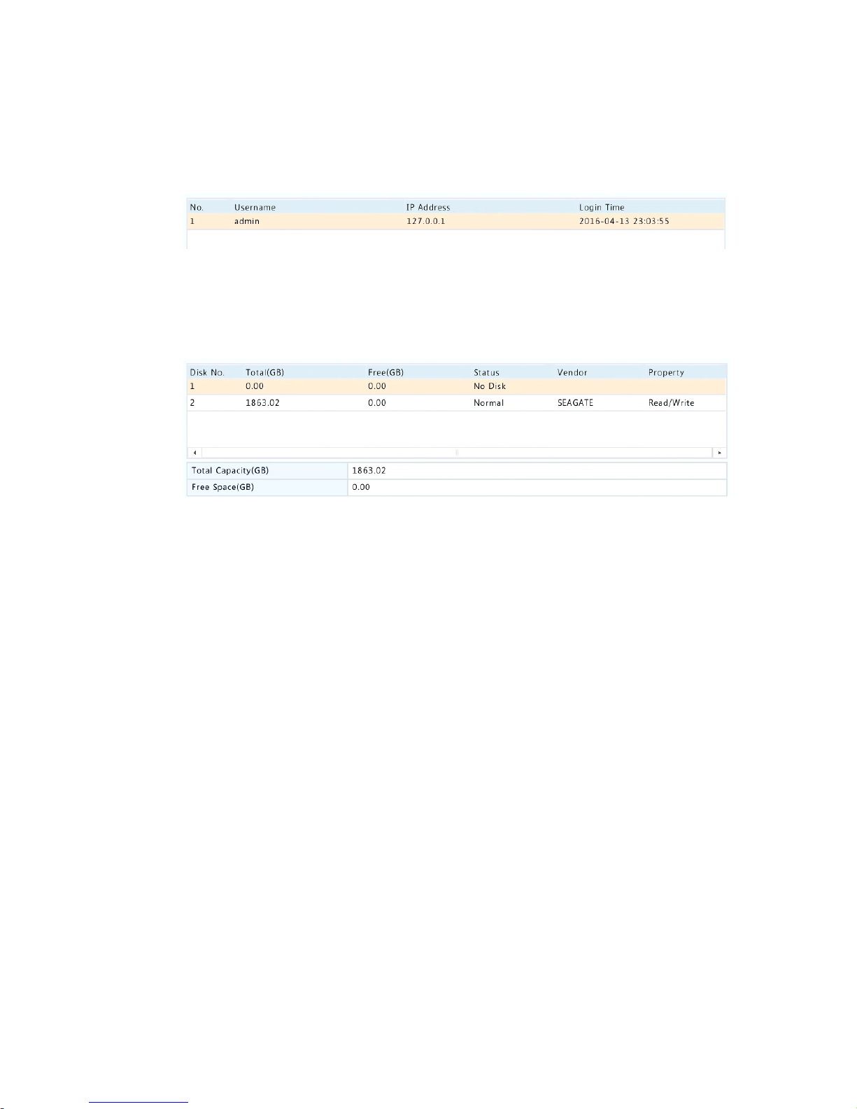
Online user
Click the Online User tab for information about users who are currently
logged in.
Disk status
Click the Disk tab to view the hard disk status and disk properties.
Decoding card status
Click the Slot Status tab to view the decoding card status. This function
is available to certain NVR models only.
System Upgrade
Upgrade the NVR under Maintain > Upgrade locally (using an upgrade
file saved in a USB storage device) or by cloud (through a cloud server).
To upgrade by cloud, ensure that the NVR is connected to a fully
functional DNS server (configured under System > Network > Basic), and
click Check to see whether a newer version is available. The time that a
cloud upgrade takes is affected by network connection status.
Page 56
53
CAUTION!
⚫ Make sure power is not interrupted during upgrade. A power failure
during system upgrade may cause startup failure. Use an
Uninterrupted Power Supply (UPS) if necessary.
⚫ Ensure network connectivity for a cloud upgrade.
10 Shutdown
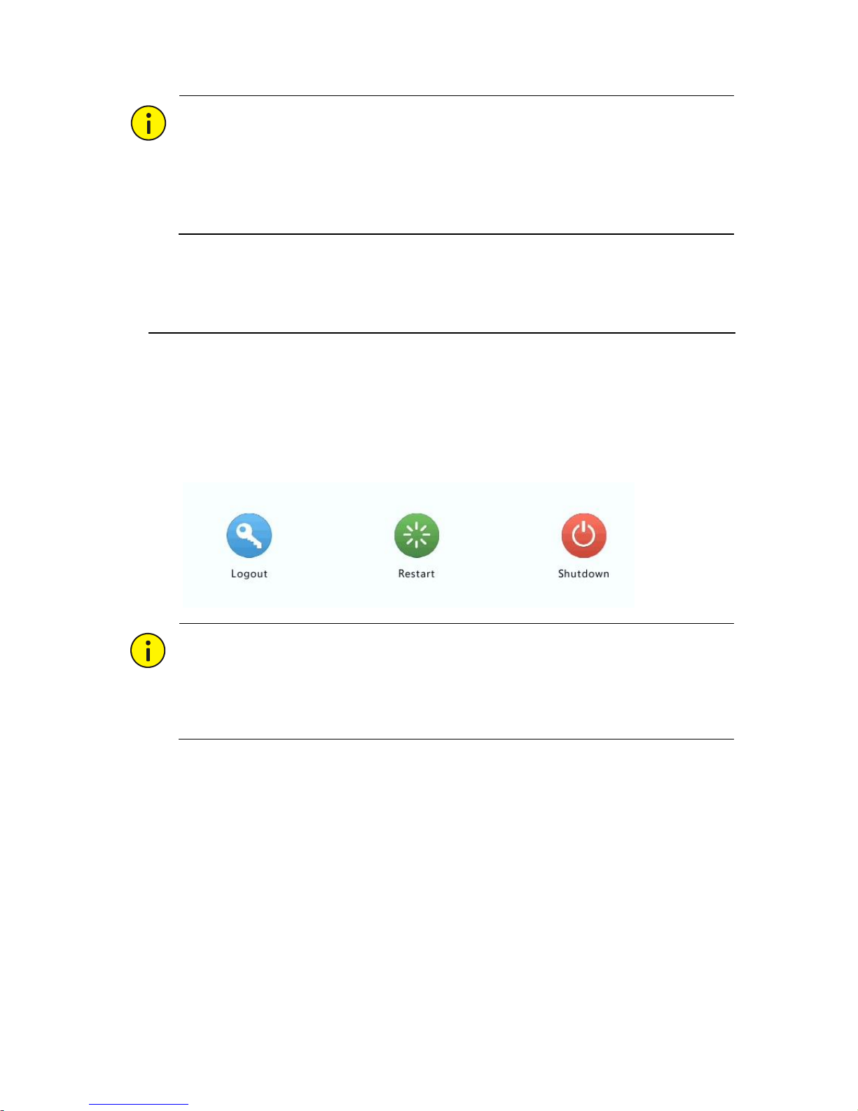
Click Shutdown to log out, restart or shut down as needed. To shut
down the NVR, you may also long-press the power button on the front
panel (if available) for around three seconds till an on-screen message
appears, and then click Yes.
CAUTION!
Unsaved settings will be lost if the NVR is shut down unexpectedly, for
example, due to a power failure. An incorrect shutdown during a system
upgrade may cause startup failures.
 Loading...