

Page 1
Automatic Sliding Door
Retrofit Drive Assembly
Installation Manual
800-437-3667
DoorControlsUSA.com
Page 2

Page 3

TABLE OF CONTENTS pg.
1. COMPONENTS 2
2. HEADER PREPARATION 2
3. DOOR PREPARAT IO N 2
4. MOTOR AND CONTROLLER INSTALLATI ON 2
5. WIRING OF ACCESSORIES 3
6. DRIVE BELT AND BRACKET INSTALLATION 3
7. CONNECTING POWER 3
8. WALK TEST 3
9. SAFETY TEST AND DOCUMENTATION 4
10. CONTROL LAYOUT 4
11. I/O CONNECTOR LAYOUT AND DESCRIPTION 5
12. HOW TO ENTER PROGRAM MODE 6
13. MENU DISPLAY SCREENS 7
14. PART NUMBERS 12
15. TECHNICAL SPECI FI C AT IO N S 12
16. WARRANTY TERMS 12
17. TROUBLE SHOOTING TIPS 13
18. WIRING DIAGRAMS 14
DC One V3 Installation Manual Page 1 of 15
M-0015 REV 06222017 P10
Page 4
NOTE: Approximate installation time: 2 to 4 hours – 1 Technician.
1. COMPONENTS
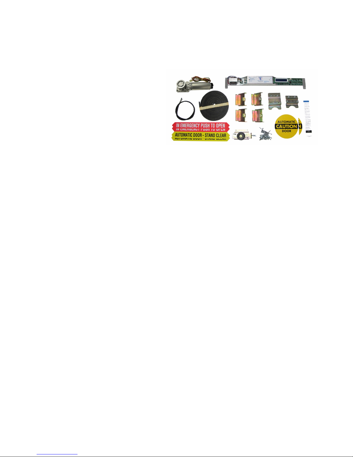
Motor / Gearbox (1)
Control (1)
Drive Belt (1) – Optional on some systems
Belt Brackets (2)
Idler / Tensioner (1) – When required
Decal Set (1)
AAADM Owner’s Manual (1)
AAADM Daily Safety Check Decal (1)
OPTIONAL:
Bottom Guides (1 or 2)
Top Rollers (2 or 4)
2. HEADER PREPARATION
WARNING – Shut off and disconnect all primary electrical power to the door header before proceeding any further.
Disconnect all sensor wiring from the control and/or interface board. Keep the wiri ng available if you i ntend to re-use the sensors
Disconnect all safety beam wiring from the control and/or interface board. Keep the wiring available if you intend to re-use the
safety beams.
Disconnect all switches from the control and/or interface. Keep the switches in place if you intend to re-use them for the retrofit.
Remove the entire existing drive system from the header (motor/gearbox, control, interface, belt, chain, cables, etc.). Do not
throw away any mounting hardware as it may be used to mount the DC One components (see drawings).
BOX CORES and USED COMPONENTS (motor/gearbox, control, etc.) use the return shipping label and ship to Door Controls.
3. DOOR PREPARATION
Remove and replace the bottom guides (If needed).
Remove and replace top rollers (If needed).
IMPORTANT NOTE:
• Manual resistance of the sliding panels, with no belt attached, should not exceed 8 lb for bi-parts, or 4 lb for
single slides. Use a force gauge to push against the door to slide it open and closed to check the resistance.
• Be sure to check for mechanical door stops at each end of the header. If door stops are missing, they may be
ordered as an accessory from Door Controls.
• Do not install new belt brackets yet, this will allow more working room when installing the control and related
wiring.
4. MOTOR AND CONTROLLER INSTALLATION
Install DC One motor/gearbox and controller per the instructions shown on the enclosed drawing.
DC One V3 Installation Manual Page 2 of 15
M-0015 REV 06222017 P10
Page 5
5. WIRING OF ACCESSORIES
Complete all wiring. Refer to the wiring diagrams in Sections 11 and 18. Be sure to complete the wiring for any accessories that
may be required as well:
• Activation Sensors
• Safety Sensors
• Safety Beams
• On-Off Switch
• Emergency Breakout Switch
• Electric Carriage Lock (accessory)
• Reduced Opening Switch (accessory)
• 1-Way Switch (accessory)
6. DRIVE BELT AND BRACKET INSTALLATION
Upon completion of all wiring, the drive belt, related brackets and idler pulley may be installed. Refer to the detailed dimensions
drawing that came with the package to determine all mounting locations. When complete, install the drive belt and tension to
result in approximately 1” to 2” deflection overall up and down at the center of the greatest span between clamp and pulley. The
belt may need to be cut to the correct length. Use a strong pair of wire cutters to make a clean cut.
Check to make sure there are no wires that could be potentially caught by the moving parts. With the belt installed and tensioned,
move the doors manually to their full open and then full closed position and ensure that they slide without binding or obstruction.
7. CONNECTING POWER
Connect and apply main power to the control.
Perform a factory reset – Refer to Sections 12 and 13.
Press the TEST button on the DC One control to trigger an activation cycle.
When the learn cycle is complete, normal operation will resume according to default values set in the control. Fine-tuning of the
control may be necessary at this point. Other than door handing and breakout polarity, the most common adjustments are for
speed, force and time. Although there are more adjustments if needed. See Sections 12 & 13 for further instructions.
8. WALK TEST
Check all functions to ensure proper operation
REMEMBER – Even if a door is d esignated for 1-way traffic, a secondary acti vation sensor is still required at the side not intended
for approach. The activation zone must extend to at least 24” out from the face of the door
With the door switch off, make sure the doors are fully closed. Check alignment of doors for proper weather-seal and ensure
that door locks properly
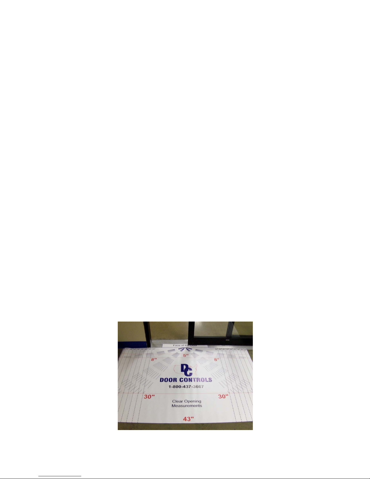
Use walk-test aides such as the dimensional mat shown below, to help outline key distances for testing sensor patterns
DC One V3 Installation Manual Page 3 of 15
M-0015 REV 06222017 P10
Page 6
9. SAFETY TEST AND DOCUMENTATION
When all DC One and sensor adjustments are complete, perform a thorough safety test to validate proper and safe performance
in accordance with current ANSI A156.10 guidelines as well as recommendations prescribed by the American Association of
Automatic Door Manufacturers (AAADM). Door Controls USA recommends this step be performed by an AAADM certified door
inspector.
• Walk toward the door at a normal pace. The door should open when you are about 4 feet from the door.
• Stand motionless on threshold for at least 10 seconds. The door should not close.
• Move clear of the area. The door should remain open for at least 1.5 seconds and should close slowly and
smoothly.
• Repeat steps 1 through 3 from the other direction if door is used for two way traffic.
• Inspect the floor area. It should be clean with no loose parts that might cause the user to trip or fall. Keep traffic
path clear.
• Inspect door’s overall condition. The appropriate signage should be present.
• Have door inspected by an AAADM certified inspector at least annually.
• DO NOT USE DOOR if it fails any of these safety checks or if it malfunctions in any way.
Be sure to place an AAADM Daily Safety Check decal on the door (usually near the On-Off switch).
Document all work, obtain signatures on all work orders, and instruct the owner on door operation. Be sure to leave a copy of
the AAADM Owner’s Manual for sliding doors with the owner or facilities manager.
10. CONTROL LAYOUT
A
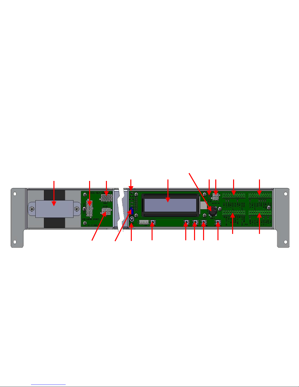
A. Transformer
B. Transformer Connector
C. Power Connector
D. Status LEDs
E. Display Screen
F. Parameter Adjustment Knob
G. Encoder Status LEDs
H. Encoder Connector
I. Sensor Connector
J. Multifunction Switch Connector
B C
T
S
D
R
F
E
Q
K. Special Modes Connector
L. Lock Connector
M. Test Button (activates door)
N. Program Button
O. Down Button
P. Up Button
Q. Reset Button
R. Lock Voltage
S. Display Intensity
T. Motor Connector
P
L
I
J
K
G
H
M
N O
DC One V3 Installation Manual Page 4 of 15
M-0015 REV 06222017 P10
Page 7
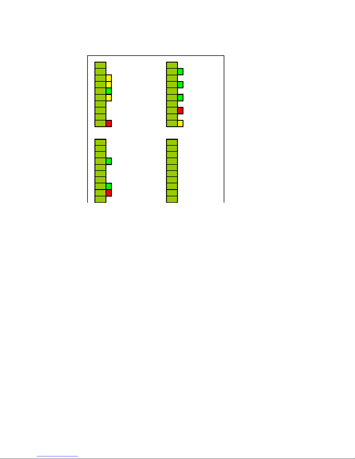
11. I/O CONNECTOR LAYOUT AND DESCRIPTION
J6 J7
1
x Common + 1 x Common +
2
x Off 2 x Emergency Open
3 x One Way 3 x Common +
4
x Partial Open 4 x Ratchet
5
x Hold Open 5 x Common +
6 x Reset 6 x Activation
7
x 24 VAC 7 x Common +
8
x 24 VAC Return 8 x Breakout
9 x Common + 9 x Common +
10
x Safety 10 x Night Mode
J5
J8
1
x 24 VAC 1 x DC One Lock
2
x 24 VAC Return 2 x DC One Lock
3
x Common + 3 x DC One Lock
4
x Inner Sensor 4 x DC One Lock
5
x 24 VAC 5 x DC One Lock
6 x 24 VAC Return 6 x DC One Lock
7 x Common + 7 x NC
8
x Outer Sensor 8 x NC
9
x Safety 9 x NC
10 x Common + 10 x NC
J6 – Multifunction Switch – Pins 1 to 6
• Compatible with DC position switches
o 5PSW1 – 5 position knob
o 5PSW2 – 5 position key
o 6PSW1 – 6 position knob
o 6PSW2 – 6 position key
• Off
o Disables ratchet, inner sensor and outer sensor inputs
o Locks door if lock is present
o Control on LED will turn off
• One Way
o Disables outer sensor in closed position
o Yellow LED is on when active
• Partial Open
o Door will not fully open
o Width is adjustable in menu
o Yellow LED is on when active
• Hold Open
o Holds the door in the open position
o Green LED is on when active
• Reset
o Resets position values
o Door will relearn on next activation
o Yellow LED is on when active
DC One V3 Installation Manual Page 5 of 15
M-0015 REV 06222017 P10
Page 8

J6 – Safety Beams – Pins 7 to 10
• Activates the door except when in the closed position
• 24 VAC power to safety beam module
• Red LED is on when active
J5 – Inner and Outer Sensors
• Separate 24 VAC connections for sensor power
• Inner Sensor
o Activates door except when off or in night mode
o Green LED is on when active
• Outer Sensor
o Activates door except in off, one way, or night mode
o Green LED is on when active
• Safety
o Activates the door except when in the closed position
o Red LED is on when active
J7 – Special Modes
• Emergency Open
o Activates the door during all modes
o Green LED is on when active
• Ratchet
o Activates door and stays open until ratchet is pressed again
o Does not activate during off, one way, or night mode
o Green LED is on when active
• Activation
o Activates the door during all modes
o Green LED is on when active
• Breakout
o Stops door motion
o Software selectable polarity (NO/NC)
o Red LED is on when active
• Night Mode
o Disables inner and outer sensors in closed position
o Door activates with emergency open and activation input only (pin 2 or 6 of J7)
o Yellow LED is on when active
J8 – Lock
• Pins 1 to 6 are used to control the DC One lock
• Lock voltage is selectable between 12 and 24 volts with toggle switch
• See wiring diagrams for detailed information
12. HOW TO ENTER PROGRAM MODE
Press both the RESET and the PROGRAM button.
Release the RESET button and continue to hold the PROGRAM button
After the display changes, release the PROGRAM button
You are now in program mode.
After making changes, press RESET to exit program mode
The control will perform a learn cycle on the first activation after a reset
DC One V3 Installation Manual Page 6 of 15
M-0015 REV 06222017 P10
Page 9
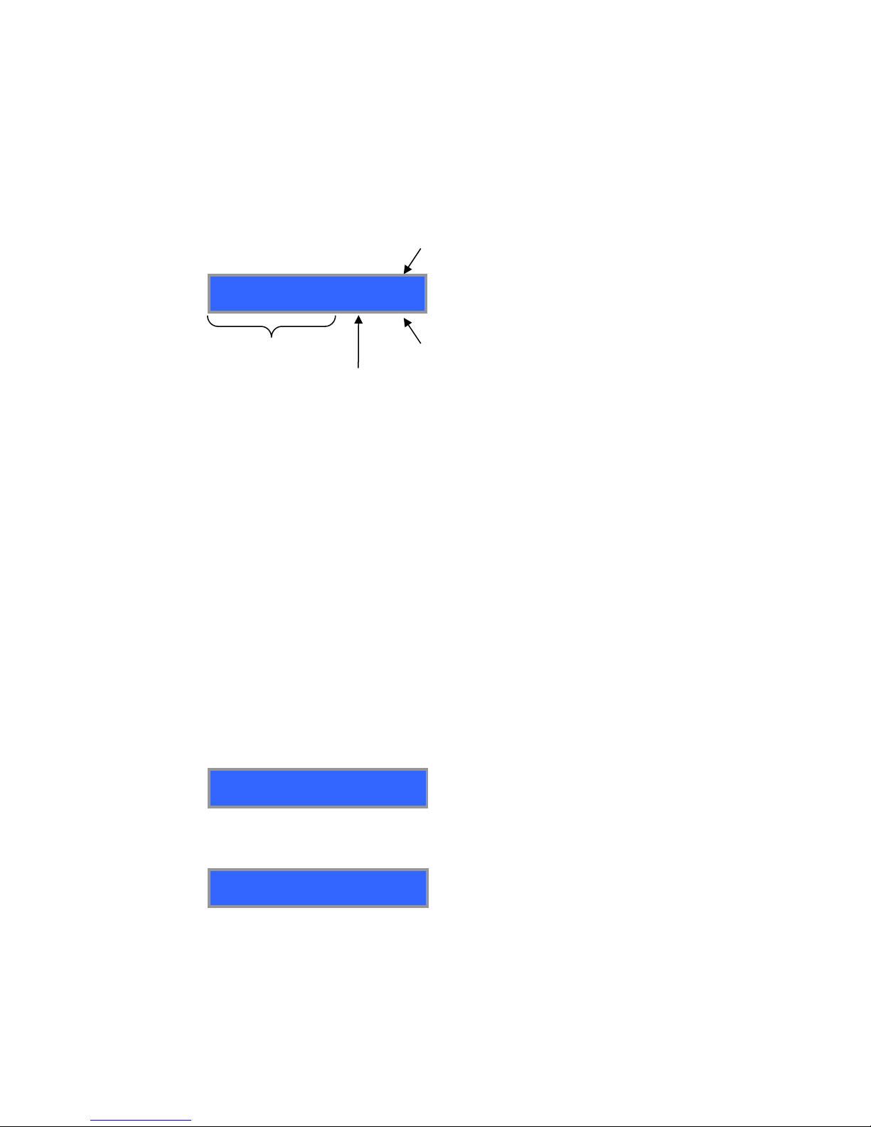
13. MENU DISPLAY SCREENS
LIFE CYCLE COUNT
00000000
TRIP CYCLE COUNT
00000000
DOOR POSITION 00258
act sf ro bo 0 X Y
Pressing the up button will cycle through the menu in the following order.
Factory default settings are shown, following a reset.
Turning the parameter adjustment knob will change the values for that setting.
Door Position
Encoder
Counts
Encoder Pulses
Status
This is a status only screen that gives the following information:
• Encoder Counts – shows the actual encoder count relative to door position
• Encoder Pulses – toggles between upper and lower case as encoder pulses are received
• Status – toggles between upper and lower case as status changes
o act/ACT – Activation
o sf/SF – Safety
o ro/RO – Reduced open
o bo/BO – Breakout
• State – shows the state of the controller
o 0 – Closed
o 1 – Opening
o 2 – Open Deceleration
o 3 – Open Check
o 4 – Open
o 5 – Closing
o 6 – Close Deceleration
o 7 – Close Check
o B – Boost Mode
o L – Learn Mode
o O – Obstruction
Life Cycle Counter
• Indicates the total number of door cycles on the control
• Non-resettable
Trip Cycle Counter
• Indicates the number of cycles since the trip counter was last reset
DC One V3 Installation Manual Page 7 of 15
M-0015 REV 06222017 P10
Page 10

Trip Counter Reset
RESET TRIP COUNTER
FAULTS DETECTED
NONE
DOOR CONTROLS
800-437-3667
DC ONE V3
FIRMWARE V 1.15
LEARN TORQUE
020.5%
LEARN OPEN SPEED
014.8%
LEARN CLOSE SPEED
014.8%
SELECT MOTOR TYPE
DC ONE V3
• Resets the trip counter
• Resettable in program mode only
Faults Detected
• Lists the fault that the control is currently under
Learn Torque
• Ranges from 5 to 100%
• Adjustable in or out of program mode
Learn Open Speed
• Ranges from 5 to 100%
• Adjustable in or out of program mode
Learn Close Speed
• Ranges from 5 to 100%
• Adjustable in or out of program mode
Motor Type
• Adjustable in program mode only
Phone Number
Software Version
o None
o Broken or Loose Belt
o Jammed Door
o Obstruction Lockout
Control will remain in hold open after 3 consecutive obstruction errors
Control must be reset or turned off to clear error
Off is preferable to prevent a relearn cycle after a reset
DC One V3 Installation Manual Page 8 of 15
M-0015 REV 06222017 P10
Page 11

Open Speed
OPEN SPEED
056.3%
CLOSE SPEED
020.9%
OPEN CHECK SPEED
012.0%
CLOSE CHECK SPEED
012.0%
OPEN DECELERATION
030
CLOSE DECELERATION
030
BOOST SPEED
030.1%
• Ranges from 5 to 100%
• Adjustable in or out of program mode
Close Speed
• Ranges from 5 to 100%
• Adjustable in or out of program mode
Open Check Speed
• Ranges from 5 to 100%
• Adjustable in or out of program mode
Close Check Speed
• Ranges from 5 to 100%
• Adjustable in or out of program mode
Boost Speed
• Acceleration from a stopped position to check speed
• Ranges from 5 to 100%
• Adjustable in or out of program mode
Open Deceleration
• Adjusts the transition between open and open check
• Higher values cause a more abrupt change between the two speeds
• Ranges from 0 to 255
• Adjustable in or out of program mode
Close Deceleration
• Adjusts the transition between close and close check
• Higher values cause a more abrupt change between the two speeds
• Ranges from 0 to 255
• Adjustable in or out of program mode
DC One V3 Installation Manual Page 9 of 15
M-0015 REV 06222017 P10
Page 12

Open Torque
OPEN TORQUE
072.0%
CLOSE TORQUE
072.0%
OPEN CHECK TORQUE
014.8%
CLOSE CHECK TORQUE
014.8%
OPEN CHECK SIZE 10"
CLOSE CHECK SIZE 05"
REDUCE OPEN SIZE 16"
HOLD OPEN TIME 3s
• Ranges from 0 to 100%
• Adjustable in or out of program mode
Close Torque
• Ranges from 0 to 100%
• Adjustable in or out of program mode
Open Check Torque
• Ranges from 0 to 100%
• Adjustable in or out of program mode
Close Check Torque
• Ranges from 0 to 100%
• Adjustable in or out of program mode
Open Check Size
• Ranges from 3” to 18”
• Adjustable in program mode only
Close Check Size
• Ranges from 3” to 18”
• Adjustable in program mode only
Reduced Open Size
• Ranges from 12” to 72” in 4” increments
• Adjustable in program mode only
Hold Open Time
• Ranges from 1 to 30 seconds
• Adjustable in program mode only
DC One V3 Installation Manual Page 10 of 15
M-0015 REV 06222017 P10
Page 13

Door Braking
DOOR BRAKING OFF
RIGHT HAND DOOR
FAIL SECURE LOCK
BREAKOUT POLARITY NO
LOCK DELAY OFF
LOAD FACTORY DEFAULT
• Should only be turned on for heavy doors
• Adjustable in program mode only
Handing
• Sets the door to either right or left hand mode
• Adjustable in program mode only
Lock Type
• Sets the lock type to either secure or safe, auto detects DC One lock
• Adjustable in program mode only
Breakout Polarity
• Configures breakout for either normally open (NO) or normally closed (NC) contacts
• Adjustable in program mode only
Lock Delay
• When enabled, there will be a delay of 1 second between activation and when the door panels
move to allow the lock to clear the door path
• Adjustable in program mode only
Load Factory Defaults
• Pressing the program key will reset all settings to factory default
• Adjustable in program mode only
DC One V3 Installation Manual Page 11 of 15
M-0015 REV 06222017 P10
Page 14
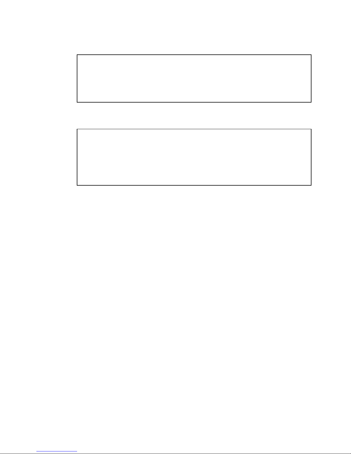
14. PART NUMBERS
Control
DC1-CONTROL
Motor
DC1-MOTOR
Power Cord
DC1-POWER CORD
Transformer*
DC1-TRANSFORMER
Belt
DC1-BELT
Lock**
DC1-LOCK FAIL SAFE or DC1-LOCK FAIL SECURE
Power Input
120 Volts AC, Single Phase
Power Consumption
150W Max.
Secondary Power Supply
24 Volt, 1A Max.
Drive Train
Molded Brushed DC Motor with Gear Reduction Assembly
Control
Microprocessor Controller
Maximum Door Weight
400 lbs (200lbs per panel for bi-part)
Operating Environment
-4F to 158F (-20C to +70C) 30% to 85% Relative Humidity
* Included with control ** Optional
15. TECHNICAL SPECIFICATIONS
16. WARRANTY TERMS
1 Year from date of purchase from Door Controls USA, Inc.
DC One V3 Installation Manual Page 12 of 15
M-0015 REV 06222017 P10
Page 15

17. TROUBLE SHOOTING TIPS
Before wiring any sensors into the DC One control, it is a good idea to apply power and test the door to ensure it will power
open and closed when the TEST button is pressed.
• Use caution during this test as the sensors will not be operational
The following inputs have status LEDs to help identify problems:
• Power
• Control On
• Door Locked
• Heartbeat
• One Way
• Partial Open
• Hold Open
• Reset
The heartbeat LED should be blinking. If not, cycle power on the control. If the heartbeat LED is still not blinking,
the control is malfunctioning and should be replaced.
If programming of the control is unsuccessful, it is easiest to restore the default values and then start over, rather
than trying to correct any faulty programming.
When power is applied, the door powers open and stays open.
• Motion or presence sensor output is being held (closed circuit). If unsure which sensor, unplug one
by one until fault is isolated. Correct as necessary.
• Safety beam is blocked or is faulty. Correct as necessary.
• Door handing is set incorrectly. Enter program mode and change hands.
Door powers closed and then stay closed.
• Press the TEST button on the face of the DC One control. Door should power open and then
close. If it does not open, door handing is set incorrectly. Enter program mode and change hands.
Door will not open or close.
• As a first step, always check the DC One digital display for error messages and proceed
accordingly.
• Breakout switch is not wired properly. If red light is on for breakout function on I/O interface, it
means that the control is in a breakout condition. Check to ensure breakout polarity is set
correctly.
• On/Off switch is not wired properly or it is in the off position. If the switch is in the on position, the
green LED to the left of the display will be on.
Important
Upon completion of your retrofit, ensure all functions of the door perform satisfactorily. Walk-test the door
according to AAADM recommended guidelines and correct all discrepancies, if any, before leaving the job site.
DO NOT compromise proper performance. If repairs cannot be immediately made, shut the door OFF and inform
the owner of any special instructions and corrective actions.
Contact Door Controls USA for further technical support when needed:
Door Controls USA, Inc.
321 VZ County Road 4500
Ben Wheeler, TX 75754
Phone: 1-800-437-3667
Fax: 1-800-356-8858
Email: [email protected]
DoorControlsUSA.com
• Safety
• Inner Sensor
• Outer Sensor
• Emergency Open
• Ratchet
• Activation
• Breakout
• Night Mode
DC One V3 Installation Manual Page 13 of 15
M-0015 REV 06222017 P10
Page 16
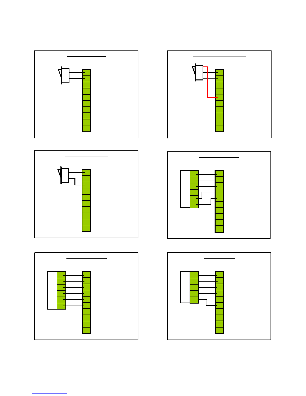
18. WIRING DIAGRAMS
ON / OFF Switch
J6
x 1 Common +
x 2 Off
x 3 One Way
x 4 Partial Open
x 5 Hold Open
x 6 Reset
x 7 24 VAC
x 8 24 VAC Return
x 9 Common +
x 10 Safety
ON
OFF
ON / OFF / HO Switch
J6
x 1 Common +
x 2 Off
x 3 One Way
x 4 Partial Open
x 5 Hold Open
x 6 Reset
x 7 24 VAC
x 8 24 VAC Retu r n
x 9 Common +
x 10 Safety
ON
HO
OFF
ONE WAY S wi t c h
J6
x 1 Common +
x 2 Off
x 3 One Way
x 4 Partial Open
x 5 Hold Open
x 6 Reset
x 7 24 VAC
x 8 24 VAC Retu r n
x 9 Common +
x 10 Safety
ON
OFF
5PSW1 & 5PSW2
J6
x
1
Common +
x
2
Off
x
3 One Way
x 4
Partial Open
x 5
Hold Open
x
6 Reset
x
7 24 VAC
x 8
24 VAC Return
x 9 Common +
x 10
Safety
1
2
3
4
5
6
x
x
x
x
x
x
x
x
x
x
x
x
6PSW1 & 6PSW2
J6
x 1 Common +
x 2 Off
x 3 One Way
x 4 Partial Open
x 5 Hold Open
x 6 Reset
x 7 24 VAC
x 8 24 VAC Return
x 9 Common +
x 10 Safety
1
2
3
4
5
6
x
x
x
x
x
x
x
x
x
x
x
x
DC One Lock
J8
x 1 Ground
x 2 Lock State
x 3 Door Locked
x 4 Lock Cmd
x 5 Solenoid -
x 6 Solenoid +
x 7 NC
x 8 NC
x 9 NC
x 10 NC
1
2
3
4
5
x
x
x
x
x
x
x
x
x
x
DC One V3 Installation Manual Page 14 of 15
M-0015 REV 06222017 P10
Page 17
DURAGLIDE FUNCTION SWITCH
J6
J7
ORANGE x
1 x
PURPLE
BROWN x 2
x
BLACK x 3 x
BLACK
PURPLE x 4
x
YELLOW x
5 x
x 6 x
x 7 x
x 8
x
x 9 x
x 10
x
On Stanley Duraglide replace label for function switches with the one included in kit (DC-3392).
DC One V3 Installation Manual Page 15 of 15
M-0015 REV 06222017 P10
Page 18

Page 19

Page 20

Door Controls USA, Inc.
321 VZ County Road 4500
Ben Wheeler, TX 75754
Phone: 1-800-437-3667
Fax: 1-800-356-8858
Email: [email protected]
DoorControlsUSA.com
 Loading...