

Page 1
iTango service manual
DH-MM1117-01
Page 2

Contents
Chapter 1 Important instructions
Preface
Fault Report and suggestions
Warnings and Attentions
Chapter2 General information
VIN location
General specification
Chapter 3 Service materials
Standard parts specification &General torque
Preparation of dismantle & replace
Washer,oil seal
Bearing and oil seal
Check connecting parts
Chapter 4 Inspection & adjustment
Inspection & adjustment of steering column
Shock absorber inspection
Braking inspection & adjustment
Tire inspection
Cable inspection & lubrication
Adjustment of light beam of headlight
Chapter 5 Body of vehicles
Front wheel Front shock absorber assy
Rear shock absorber assy
Pull rod assy. Steering knuckle&wheel bearing assy
Swing arm assy, parking bracket holder.
Chapter 6 electric parts introduction & malfunction service
Location of electric parts
Function introduction of electric parts
Electrical schematic Plug access checking Fault phenomenon & service methods
Page 3

Chapter 1 Important instructions
Preface
iTango's specifications, maintenance procedures, adjustments and diagnostics will be introduced in this service manual.
The service provider that authorized by Zhejiang Doohan Technology Co., Ltd. should well understanding this manual and provide
the best after service for the end users.
All products, special tools and parts has been referred in the user manual, you should obtain it from Zhejiang Doohan Technology
Co., Ltd.
The deadline of information is June 30, 2017
No part of this manual may be reproduced or transmitted in any form without the written permission of Zhejiang Doohan Technology
Co., Ltd.
Page 4

Fault report & suggestion
We are willing to accept or update if you find any fault in the service manual or suggestions for us.
Any fault report and suggestions, you can sent mail to Zhejiang Doohan Technology Co., Ltd. The contact information as follows:
Zhejiang Doohan technology co.,ltd after sales department.
Additional information you should submit as follows:
Your name
Your VIN
The description for the problem you faced
Necessary information (sample or page of marked)
Zhejiang Doohan Technology Co., Ltd. will reply to your question as follows process:
Submit your questions to related service engineers
The related engineers will double analyzing,checking or testing to find answer
Update answers to you within 10 working days.
Welcome to submit any problems whatever you cared to the service department of Zhejiang Doohan Technology Co., Ltd.
Page 5

Warnings and Attentions
Definition
The maintenance information listed in the service manual to assist the technician for diagnosing and servicing in order to the vehicle
can running normally; however, if not operated as recommended, some processes may be dangerous. The warning and caution
items are made to prevent danger, but not all of the dangers can be expected. These information is prominently placed in the service
manual in order to prevent the following items:
⚫ Serious injury to the technician
⚫ Damage the vehicle
⚫ Unnecessary vehicle maintenance
⚫ Unnecessary parts replacement
Warning definition
When you see the warning item, it means you should take the necessary measures or not take prohibited measures. If you ignore the
"warning", the following consequences will be faced:
⚫ Serious injury to the technician
⚫ Serious injury to the other technician on the same working area
⚫ If the vehicle is improperly repaired, the driver will be seriously damaged.
Attention definition
"Attention" requires special attention to the necessary measures or prohibited measures. If you ignore "attention", the following
consequences will be faced:
⚫ Vehicles damaged
⚫ Unnecessary vehicle maintenance
⚫ Unnecessary parts replacement
⚫ System and parts abnormality or performance defects.
⚫ System or parts damaged which support for maintenance of system or parts.
⚫ System and parts abnormality or performance defects which support for maintenance of system or parts.
⚫ Damage the fasteners, Basic tools or special tools.
⚫ Brake Fluid leakage
Warning about disconnecting the power supply
Warning: the key must be on the "OFF" or "LOCK" position before maintains any electrical parts, and all electrical load must be
"OFF" unless it is available as defined by other instructions in the operation procedure. If the tool or the exposed electrical terminal,
the battery cable is necessary to disconnect. If violate these safety instructions, which may result in injury or damage to person and
vehicles.
Warning about irritation of brake fluid.
Warning: brake fluid is stimulus on the eyes and skin. take the following measures once in contact.
Eye –thoroughly wishing with water.
Skin- washing with soap and water.
If swallowed - see a doctor immediately
Attentions of fasteners
Special attentions: Use the correct fasteners in the correct position. The replaced part number of fastener must be correct. Do not
use paint, lubricants or corrosion inhibitors on fasteners or fastener connection surfaces unless other instructions. The torque and
coupling force of the fasteners will be affected or damaged by those materials. When installing the fasteners, be sure to tight the
fastener with correctly torque based on the right tightening sequence .
Page 6
Chapter 1 General information
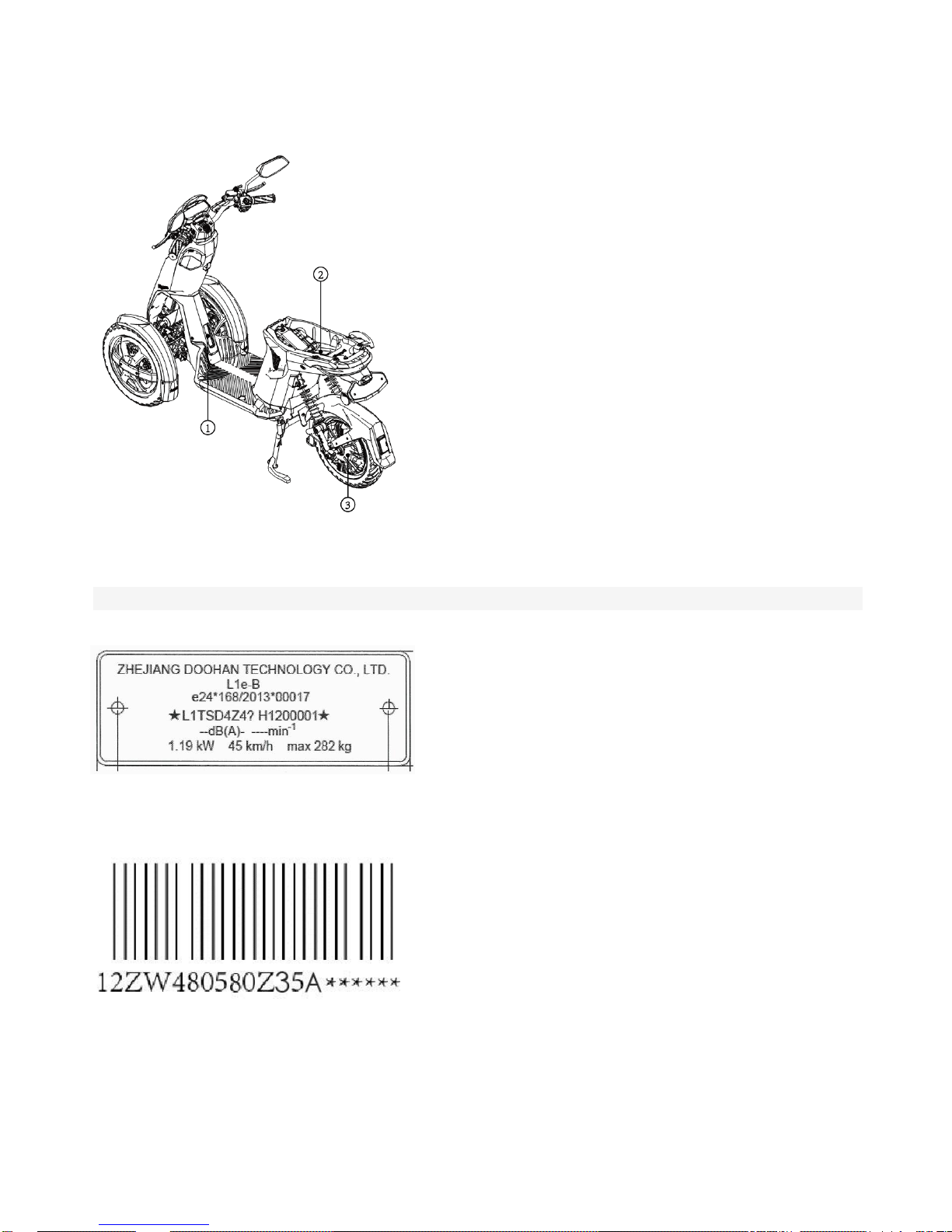
VIN location
When the vehicle is registered or received a traffic license, it is necessary to report the vehicle identification number and the motor
number. also need to be provided the above number for quality claim.
① Vehicle identification number (VIN) sign belongs to the vehicle's legal identifier.
☆L1TSD4Z4*********☆
②
Vehicles nameplate information.
③Motor series No.
Page 7
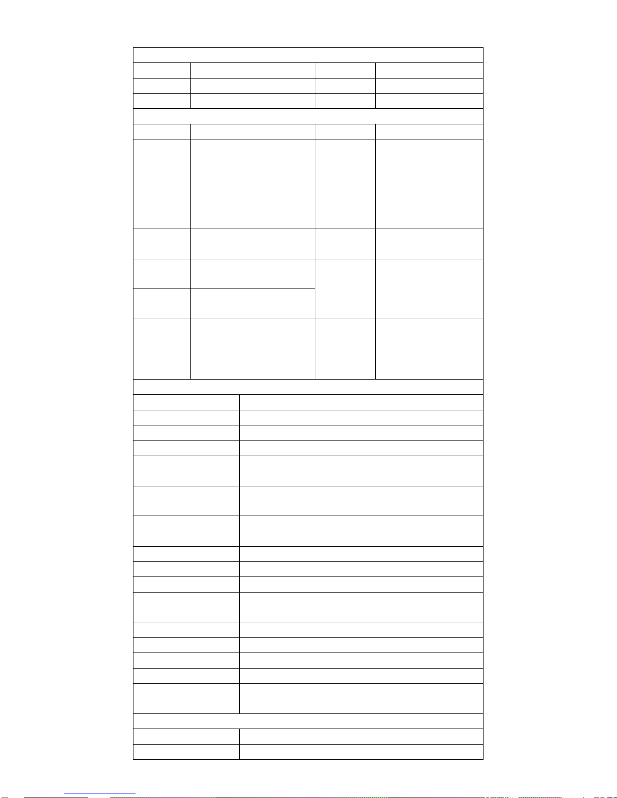
General specification
Main dimension
length
1648mm
width
651mm
high
1110mm
wheelbase
1150mm
front track
460mm
Main performance
curb weight
74kg(not include battery)
Front and
rear axle
distribution
of curb
weight
Front 23kg/rear 33kg(not
include battery)
Top
designed
speed
iTango
Classic(DH-05-10):
25km/h;
iTango
HO(DH-05-12):
45km/h
rated
voltage
48V
load
capacity
200kg
Brake
distance(dry
road)
≤2m(20km/h)
≤3.5m(30km/h)
person
2
Standard
power
consumptio
n
iTango Classic: 50KM(25km/h)
iTango HO:
50KM(45km/h),70KM(25km/h)
Braking
distance(wet
road)
≤3m(20km/h)
≤4m(30km/h)
Frame
front shock absorber
Sleeve& oil damping
rear shock absorber
Sleeve & oil damping
front tire spec.
70/90-12×2
rear tire spec.
90/70-12
Front wheel tire
pressure(kpa)
225±10
rear wheel tire
pressure(kpa)
225±10
wheel model(aluminum
alloy)
front 2.15-12 inch aluminum wheel
rear motor
2.15-12 motor
front brake
disc brake
rear brake
disc brake
minimum ground
clearance
142mm
seat height
740mm
max leaning angle
≤30°
max steering angle
≤32°
turning radius
2.50m
max drop height of front
wheel
180mm
battery system
battery model
18650 lithium battery
voltage
48V
Page 8
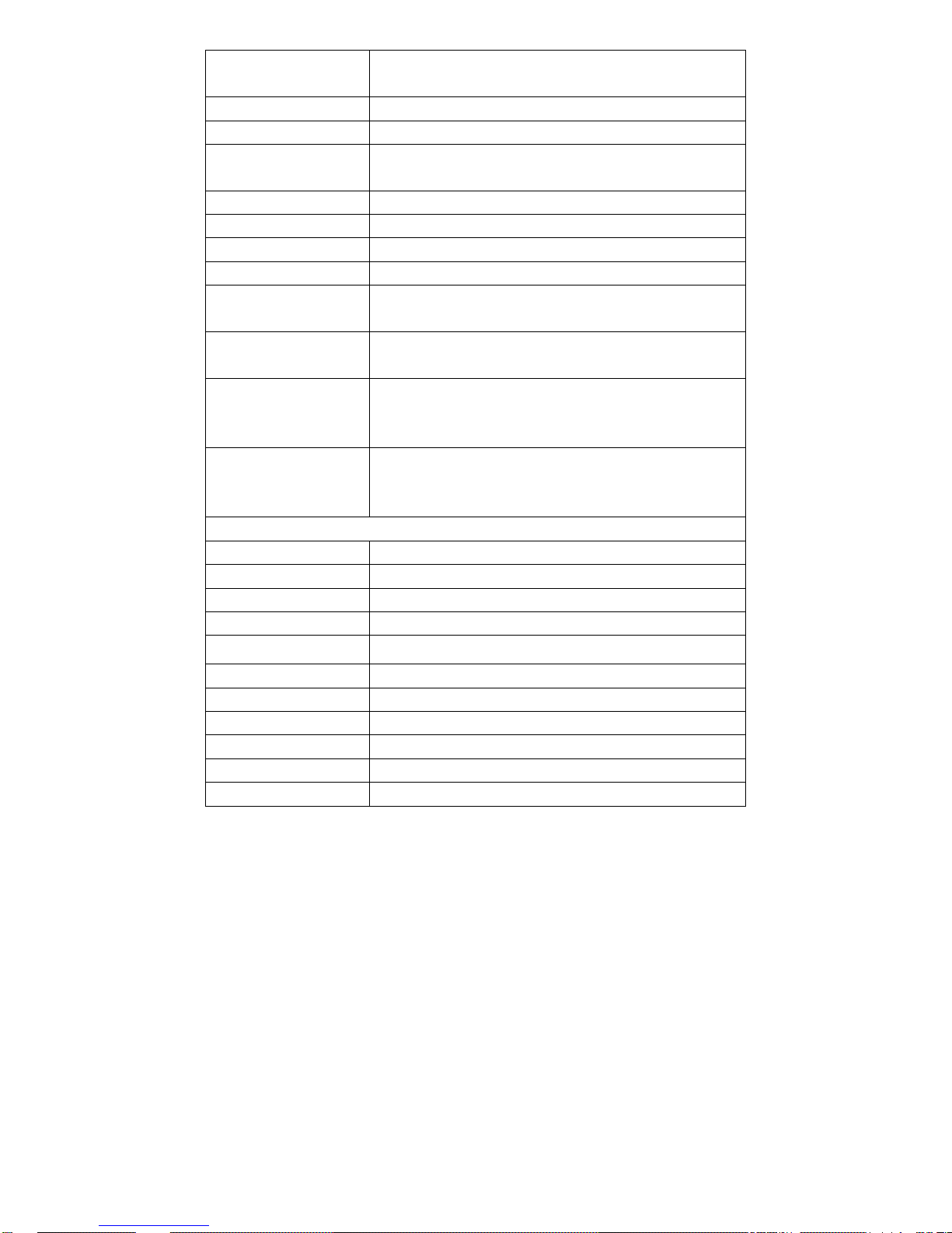
capacity
20AH(DH-05-10)
26AH (DH-05-12)
charger input voltage(V)
AC 220V or 110V(optional)
charger output voltage(V)
58V
standard charging
current
3A(iTango-C)
5A(iTango-H)
standard charging time
6H
max range
50KM
battery weight
10KG
battery recycle times
500 times
range of battery using
ambient temperature
-20℃ to 60℃
range of battery storage
ambient temperature
-20℃ to 60℃
range of battery charging
ambient temperature
0℃ to 45℃
Battery protection system
over discharging protection, short circuit protection, overheat
protection, over charging protection, over current protection,
battery balance protection
others
USB charging port
5V、1A
dashboard
LCD dashboard
fuse spec.
5A
headlights spec.
12V LED
front locating lights spec.
12V LED
front turning lights spec.
12V LED
rear turning lights spec.
12V LED
taillights spec.
12V LED
license plate lights
12V LED
rear mirror
Non-circular paint rearview mirror ,M8 mirror pole
gross weight
84kg(include 1 set battery)
Page 9
Chapter 2 Services materials
Standard parts specifications and general torque
To inform the customer about the standard parts specifications and corresponding maintenance tools.
According to the ISO standard thread depth to define the locking torque of the standard firmware. The locking torque of the special
components or assembly is described in the relevant sections of the manual. To tighten the multi-firmware assembly to the specified
torque in a crisscross and progressive manner avoid bend. Unless otherwise specified, the locking torque should be based on the
cleaning and drying threads, and the components should be kept at indoor temperature.
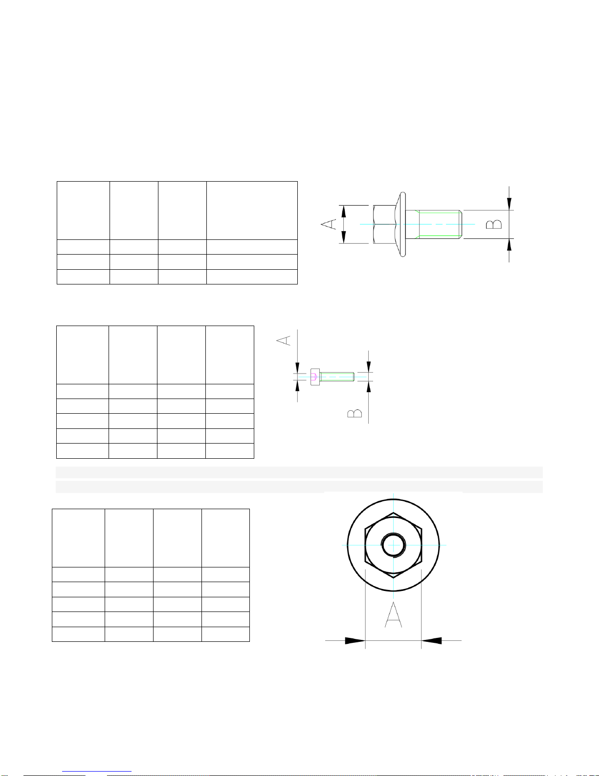
1, The national standard GB / T 5789-2000 for hexagonal flange bolts, standard parts specifications, maintenance tool specifications
and general torque as following table:
2, The national standard GB / T70.1-2000 for hexagon head bolts, standard parts specifications, maintenance tool specifications and
general torque as following table:
3. The national standard GB / T 6177.1-2000 for hexagonal flange nuts, GB / T6187.1 for hexagonal flange self-locking nuts,
standard parts specifications, maintenance tool specifications and general torque as following table:
4, The national standard GB / T70.2-2000 for hexagon flat round head bolts, standard parts specifications, maintenance tool
specifications and general torque as following table:
A
B (spec.)
Open/wre
nch&sock
et
General torque( N.m)
10mm
M6
10#
10~13
12mm
M8
12#
25~35
14mm
M10
14#
63~80
A
B (spec.)
Open/wre
nch&sock
et
General
torque( N.
m)
4mm
M5
4#
4~7
5mm
M6
5#
10~13
6mm
M8
6#
25~35
8mm
M10
8#
63~80
A
B (spec.)
Open/wre
nch&sock
et
General
torque( N.
m)
7mm
M4
7#
2~3
8mm
M5
8#
4~7
10mm
M6
10#
10~13
12mm
M8
12#
25~35
14mm
M10
14#
63~80
Page 10
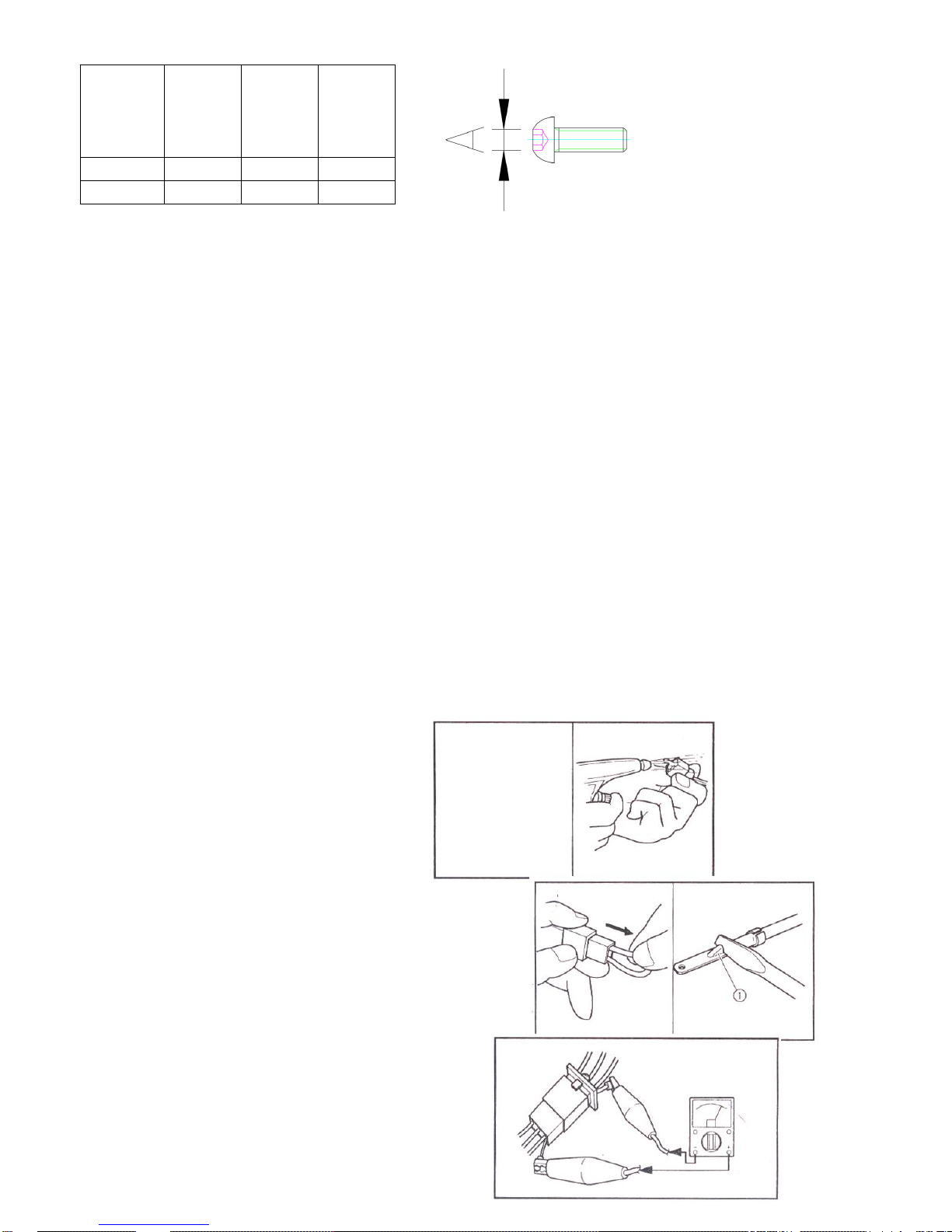
5, The national standard GB / T 845-1985 for cross-slot head tapping screws, GB / T818-2000 for cross-groove round head screws,
maintenance tools for the unity of the screwdriver. Torque is not required, only need to be tighten.
Preparation of disassemble & replacement
①Before cleaning or removing, clean the dust, dirt and foreign matter on the vehicle.
② When disassembling, be sure to place the pairing parts with groups. Pairing parts must be reused or replaced in groups.
③ When disassembling, clean all parts and place them in the tray based on disassembly order. In doing so, it can save assembly
time and ensures that parts are installed correctly.
④ Keep all parts in a location away from fire and water
Washer and oil seal
The washer surface, oil seal must be cleaned before assembled.
Bearing & oil seal
To keep clearly for the mark of manufacturer and series number when install the bearing and oil seal, When installing the oil seal, to
spread on the oil seal lip by a small amount of grease of lithium soap base. To lubricate the bearing by lubricating oil after installed.
Attention:
Do not use compressed air to rotate the bearing, which can damage the bearing surface.
Inspect the connecting parts
Check wiring, coupler joints whether with dirt, dust or water and so on.
1.Connection:
①wiring
②coupler
③connector
2. Inspection
①wiring
②coupler
③connector
Water stain - dry with air guns
Dust, dirt - repeated remove and connection several times
3. Inspection
①check all connecting part
②Loosen joint parts: correct connection
Attention
Regain it If the pin on the terminal is flattened.
4.connection
①wiring
②coupler
③connector
A
B (spec.)
Open/wre
nch&sock
et
General
torque( N.
m)
3mm
M5
4#
4~7
6mm
M8
5#
25~35
Page 11
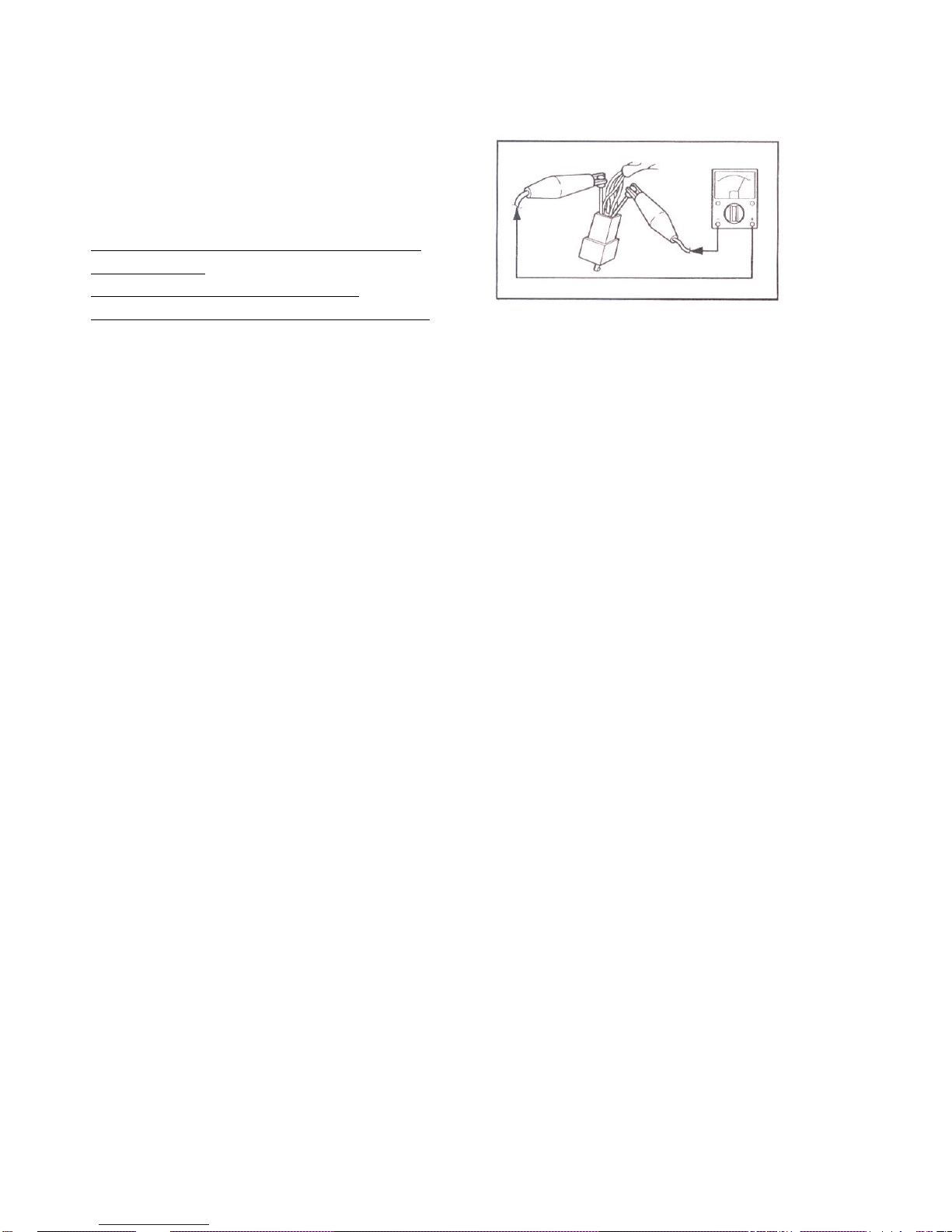
Attention
Make sure all joint part have been locked.
5.Inspection
(Using multimeter) to continuously check other related items.
Attention
If there is no need to continue to check the items, please
clean the terminals.
follow up steps 1 to 3 to check the wire jacket.
To correct it quickly, use the contact 【Contact restorer】.
Page 12
Chapter 3 Inspection & adjustment
This chapter contains all the information what is items must be checked and adjusted. If regularly implement these maintenance
procedures, it will make the vehicle more smoothly driving and life can be extended. The cost of relative maintenance will be down.
The information has been described in this chapter applies to vehicles that are not sold and sold. All service technicians should be
familiar with all information in this chapter.
Steering column inspection&adjustment.
1. Place the vehicle on a flat table. Put up the main stander to let the front wheel off the ground.
2.inspection
⚫ Steering column
Hold the front wheel and shake it up and down.
Steering column is jammed or loosened – adjust it
3. Remove
⚫ Front panel and tools box(refer to chapter 4 :plastic parts)
4. Adjustment
⚫ Steering column
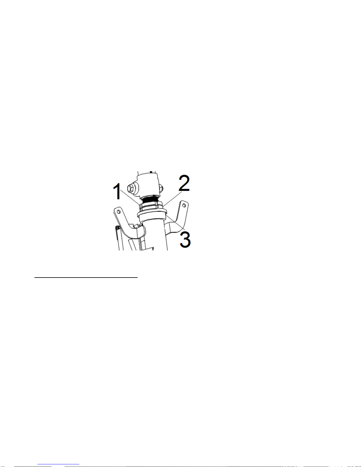
a. Remove the locking nuts 1.
b. Loose locking nuts 2, then use the ring wrench to lock based on the specified torque.
Attention
Don’t allow to lock the round nuts too tight.
C. Check the rotation of steering column whether it is loosen or stuck. If stuck, please check the top & lower bearing of top tube. If
damaged - replace.
D. Use the ring wrench to fix the lock nut 2 and lock the upper locking nut 1.
5. Installation
⚫ Front panel and tool box(refer to chapter 4 plastic parts).
Inspection of shock absorber
Inspection
⚫ Inner pipe of shock absorber
Damage/scratch--replace.
⚫ oil seal
leakage-replace
⚫ Check whether the action of shock absorber is working smoothly.
If not working smoothly--please change a new one.
Inspection & adjustment of brake
1. Inspection
⚫ free clearance of brake handle
⚫ Over standard value-adjustment.
Page 13
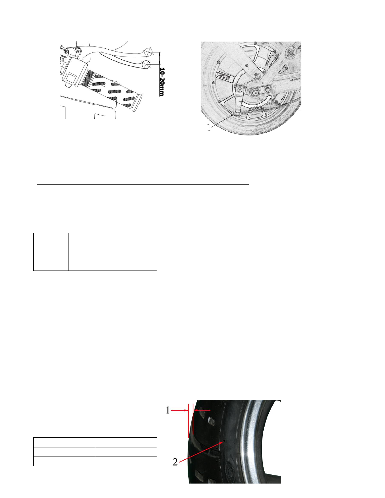
Attention
The free clearance of brake handle is 10-20 mm subject to the end of the brake handle.
Inspection & adjustment of rear drum brake
1. brake operation
2. inspection
⚫ wear indicator
Attention
When the wear indicator points to the wear limit line, replace the whole brake block.
3. adjustment
⚫ free clearance of brake handle
⚫ Rotate the rear brake nut 1 with clockwise and counterclockwise direction until to fit the specified free clearance of brake
handle.
clockwise
Increased, free clearance of brake
handle
countercloc
kwise
Decreased, free clearance of
brake handle
Attention
To make sure the brakes are not towed after adjusting the free clearance of brake handle.
Tire inspection
The following procedure is suits for inspection of front & rear tire
1. Tire checking
① Tire pressure
Over standard value( standard:225±10KPa): Adjust tire pressure.
Attention
⚫ Please check and adjust the tire pressure when the tire temperature is equal to the outdoor temperature.
⚫ Riding an overloaded vehicle can cause damage to the tire or accidental injury.
⚫ Do not overload.
2.tire surface
Ⅰtire tread depth
Ⅱwear indicator
Min tire tread depth
front tire
rear tire
1.5mm
2.0mm
Page 14
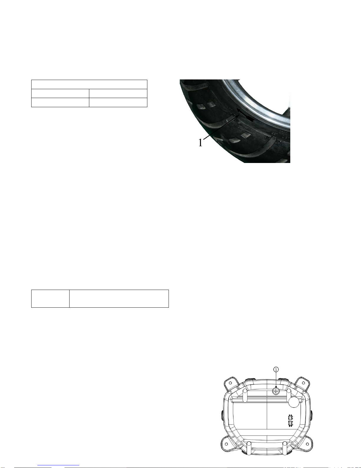
If damaged or scratched, please replace.
Attention
Don’t try to repair a tire which has been punctured. If must to repair it, please be careful and replace with high quality tires as soon as
possible.
tire spec.
front tire
rear tire
70/90-12
90/70-12
1:The tire has a sign of the direction of rotation
Attention
When the tires are installed, keep the symbols of tire tread to
toward the rotating direction of the wheel.
3. Rim inspection
⚫ rim
⚫ If damaged or scratched, please replace.
Attention
If rime is damaged or deformed, do not repair it, please replace with a new one.
Inspection & lubrication of cable
The following procedures applies to all cables.
1.Inspection
⚫ cable
Damaged--replacement
2. Inspection
⚫ cable operation
Poor operation -lubrication
lubricant
Engine oil or suitable wire rope lubricants
Attention
⚫ The damaged cable will affect the function. Please replace the cable as soon as possible.
⚫ Hold the cable end vertically and drip little lubricants in the cable or use the appropriate lubrication equipment.
⚫
Adjustment of headlights beam
1. Remove
⚫ front panel
2. adjustment
⚫ Rotate the adjusting screw with clockwise ①, the headlight beam down
⚫ Rotate the adjusting screw with counterclockwise ①, headlight beam up
Page 15
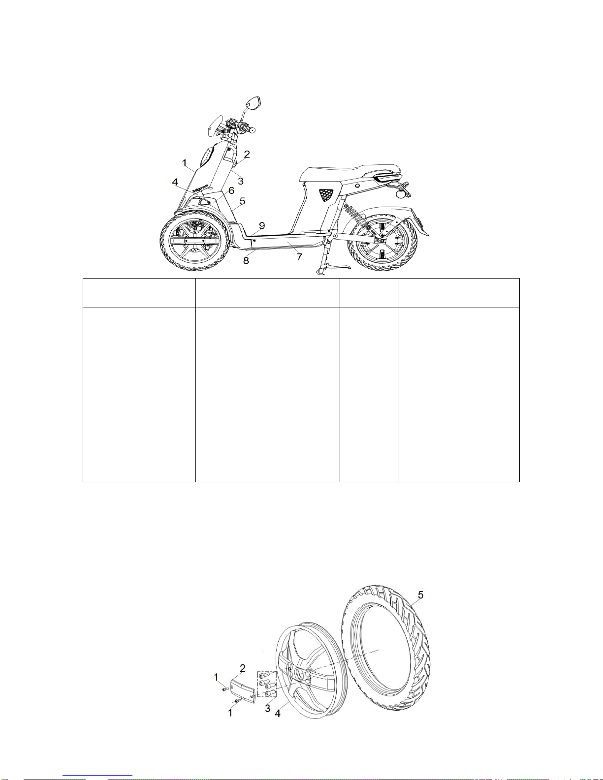
Chapter 4 Vehicles Body
Plastic parts
Sequence of Operation
Spare parts name
Quantities Remarks
1
2
3
4
5
6
7
8
9
Remove plastic parts
Front panel
Helmet hook
Tool box
Lower interior lining panel,Front
panel lower liner
Lower part, Tool box
Frame left/right fender
Right/left strip
Frame base plate
Pedal
2
1
4
1
1
1
1
1
1
Remove parts as sequence.
Parts assembling with the
reverse order of
disassembling.
Front wheel
Page 16
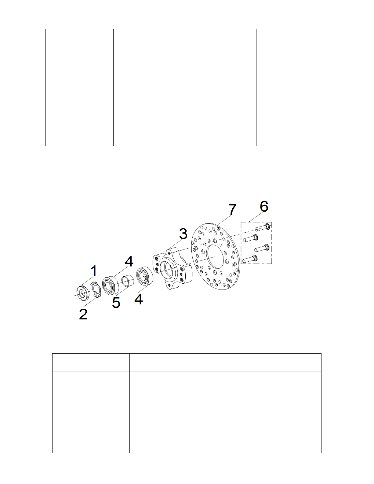
Sequence of Operation
Spare parts name
Quantiti
es
Remarks
1
2
3
4
5
Remove front wheel
Hexagon socket head cap screws, M5×10
Trim strip, Front axle.
Hexagon socket head cap screws M10×25
Front aluminum rim
Front tire
2
1
4
1
1
Disassemble parts in order
Attention
To hold up the vehicle by
appropriate bracket to
suspend.
Parts assembling with the
reverse order of
disassembling.
Disc brake & bearing
Sequence of Operation
Spare parts name
Quantities Remarks
1
2
3
4
5
6
7
Remove disc brake
Round nut
Retaining washer
Disc brake holder
( 6004-2Z )bearing
Bushing
Screw,Disc brake screw
Front disc brake
1
1
1
2
1
4
1
Disassemble parts in order
Attention
To hold up the vehicle by
appropriate bracket to suspend.
Parts assembling with the
reverse order of disassembling.
Page 17
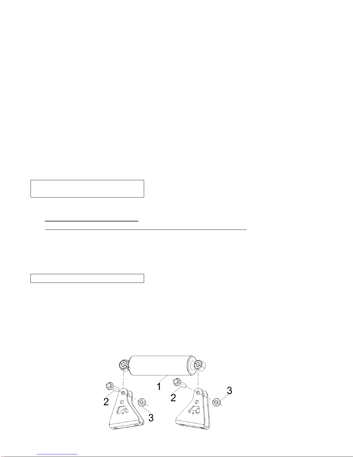
1.Inspection
⚫ Wheel bearings: if front wheel rotation is not smooth or loose, please replace the wheel bearings.
⚫ Bushing
Damaged or scratched-replace.
Inspection of front disc brake
To inspect and adjust the brake block as follows.
1. Inspection
⚫ Shoe block, Front hydraulic brake.
Shiny parts - repair
To polish with raw emery paper
Attention
To clean the shoe block after grinded by raw emery paper.
2. Measurement
⚫ The thickness of the shoe block of front hydraulic brake
Overstep standard value - replacement.
The limited thickness of shoe block: 1.5mm
Attention
⚫ Do not leave oil or butter on shoe block.
⚫ Replace whole shoe block if abrasion is out of limited value for any side of shoe block.
3. Measurement
⚫ Thickness of brake disc
If overstep the standard value - replace the brake disc.
The limited thickness of shoe block: 3 mm
4. Inspection
⚫ Cross section of brake disc.
if adhesive oil - cleaning
To wipe with cloth of lacquer diluent or oil cleaner.
Scratched - maintenance.
To polish the scratched parts with raw emery paper
Front Shock Absorber Assy
Page 18
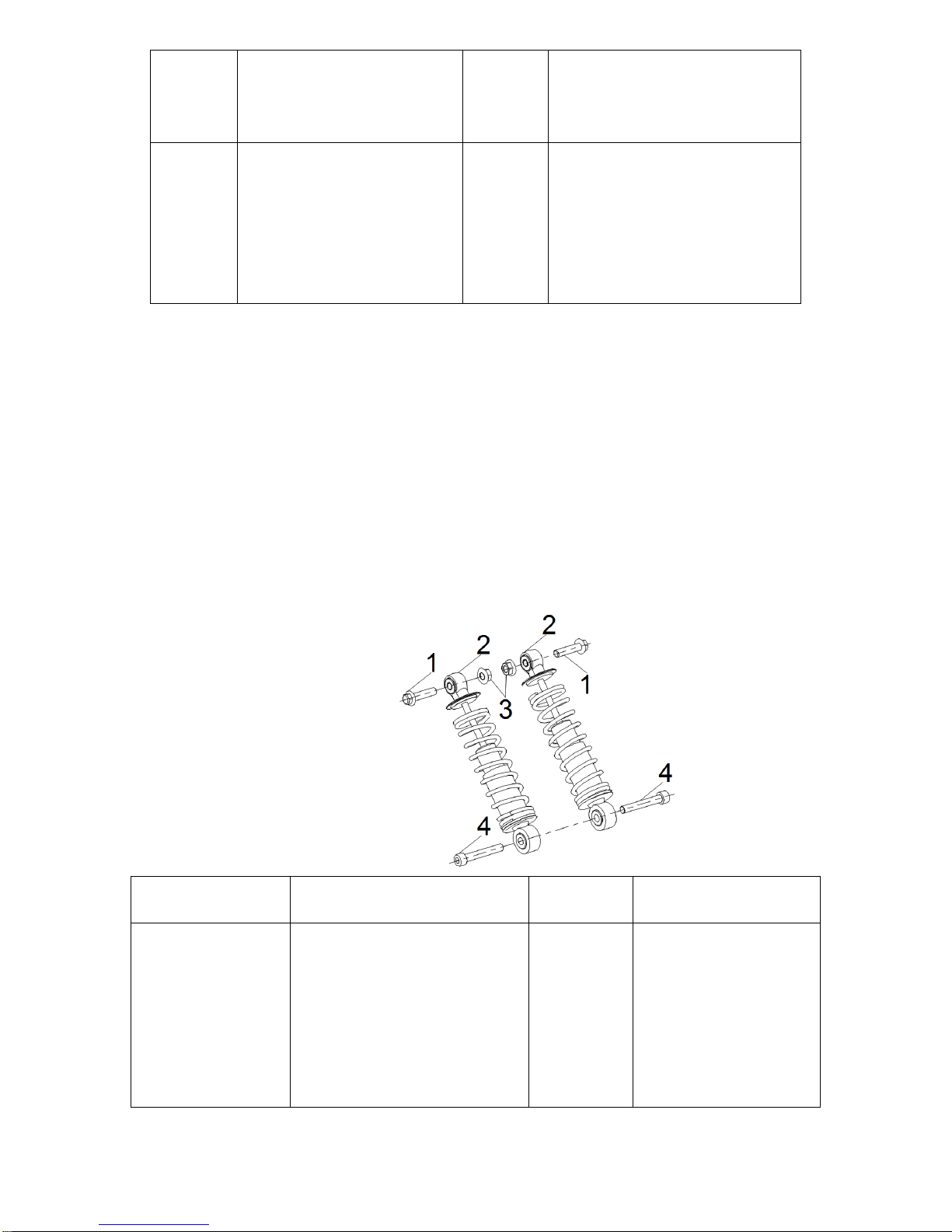
Sequence
of
Operation
Spare parts name
Quantities Remarks
1
2
3
Disassemble the front shock
absorber assy
Front shock absorber assy
M10×45 ,Hexagonal flange bolt
M10,Hexagonal flange nylon
self-locking nut
1
2
2
Disassemble parts in order
Parts assembling with the reverse order
of disassembling.
Inspection of shock absorber
⚫ Shock absorber rod
Deformed/damaged--replace shock absorber assy.
⚫ Shock absorber
Leakage--replace shock absorber assy.
⚫ Spring
Wear/damaged--replace.
⚫ Oil seal of dust proof
Wear/damaged--replace
⚫ Bolt
Deformed/damaged/worn out--replace
Rear Shock Absorber Assy
Sequence of Operation
Spare parts name
Quantities Remarks
1
2
3
4
Disassemble rear shock absorber
assy
M10×40 ,Hexagonal flange
Rear shock absorber
M10 Hexagonal flange nylon
self-locking nut
M10×60,Hexagonal round head
screws
2
2
2
2
Disassemble parts in order
Parts assembling with the
reverse order of
disassembling.
Page 19
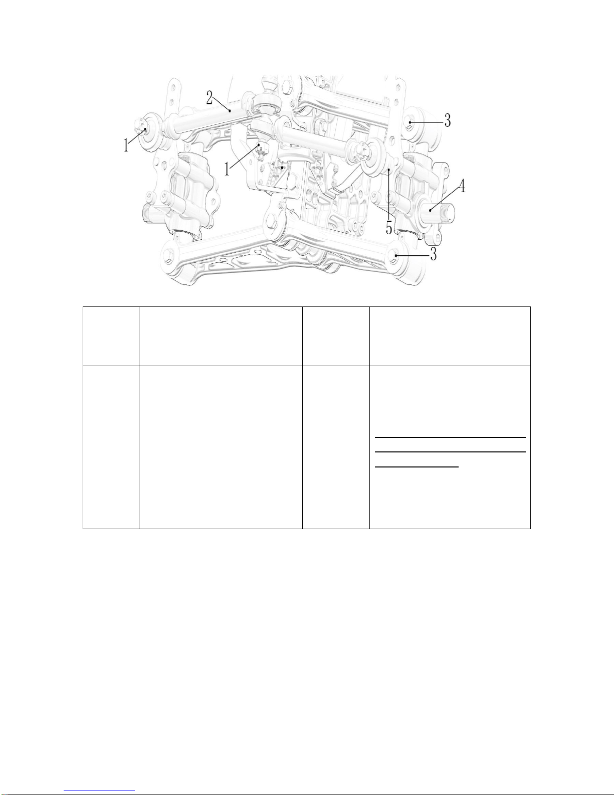
Ass,Pull rod of ball head, Steering knuckle axletree assy
Sequence
of
Operation
Spare parts name
Quantities Remarks
1
2
3
4
5
Disassemble the ball head rod assy
M10,Hexagonal flange iron self-locking
nut
Pull rod of ball head, assy
M10×60,Hexagonal flange bolt
Steering knuckle axle assy
Spacer assy,bracket plate of steering
knuckle.
2
1
2
1
1
Disassemble parts in order
Attention
Both sides is symmetrical, Don’t
need to remove both sides when one
side need to service.
Parts assembling with the reverse order
of disassembling.
Page 20
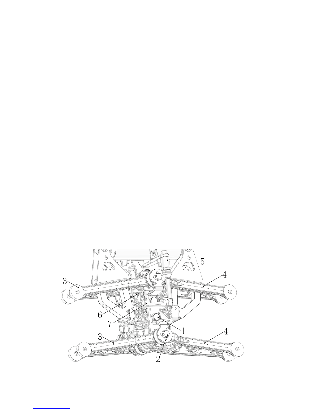
Inspection, pull rod of ball head.
⚫ Pull rod
Bend/damaged——replace the assy of pull rod of ball head.
⚫ Ball head bearing
Rotation is not flexible——clean the surface mud
Damage/loosen——replace ball head assy
⚫ Hex nut
Loosen——adjustment
⚫ Bolt
Bend/damage/wear——replace
Inspection of steering knuckle axletree assy
⚫ Steering knuckle axletree
Bend/damage——replace the steering knuckle axletree assy
⚫ Spacer assy of steering knuckle bracket plate
Bend/damage——replace
⚫ Bearing
Rotation is not flexible——clean the surface mud
Damage/loose——replace steering knuckle axletree assy
⚫ Oil seal of dust proof
Damage/scratched——replace.
⚫ Steering knuckle rotary bearing
loosen——adjustment.
⚫ Bolt、nut
Bend/damage/scratched——replace.
Swing arm assy
Fixed seat of parking bracket
Page 21
Inspection of swing arm.
⚫ Assy,Swing arm
Bend/damage——replace swing arm assy.
⚫ Bearing
Rotation is not flexible——clean the surface mud.
Damage/loose——replace.
⚫ Oil seal of dust proof
Damage/scratched——replace.
⚫ Bolt
Bend/damage/worn out——replace.
Inspection,Fixed seat of parking bracket
⚫ Fixed seat, Parking bracket.
Bend/damage——replace parking bracket holder
⚫ parking PIN
Rotation is not flexible——clean up surface mud.
Damage/scratched——replace.
Sequence of Operation
Spare parts name
Quantities Remarks
1
2
3
4
5
6
7
Disassemble swing arm assy
M10×20,Hexagon socket head
cap screws
M10×150,Hex bolt
Right swing arm assy
Left swing arm assy
Connecting rod of steering
column
Parking PIN
Fixed-seat,parking bracket
2
2
2
2
1
1
1
Disassemble parts in order
Attention
Both sides is symmetrical,
Don’t need to remove both
sides when one side need to
service.
Parts assembling with the
reverse order of disassembling.
Page 22
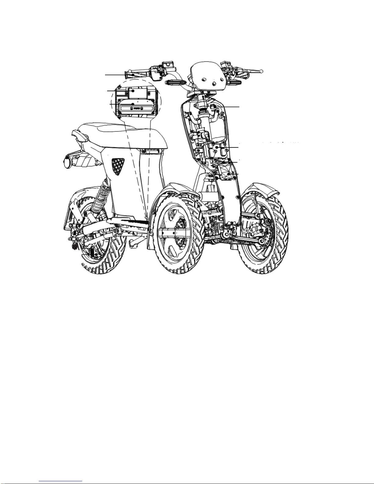
Chapter 5 introduction of electric parts & maintenance of malfunction
Location of electric parts
Accelerator
DC-DC converter
controller
USB charging port
VCU-anti-theft device
horn
motor
Page 23

Function introduction of electric parts
Battery:
The battery is power for electric scooter. It is 18650 ternary lithium battery cells from Japan and South Korea system for our
E-scooters. by the series To enhance the total capacity of the battery with series system and improve the total voltage of the battery
with parallel system, To complete the management of the battery by BMS system, BMS functions including over discharge protection,
overcurrent protection, temperature protection, short circuit protection, balanced the dropout voltage of battery cells, SOC power
display, CAN communication, The battery will automatically dormant and stop output when the output current is lower than 2A, the
battery plug can be hot-swappable, battery output Controlled by K- (Ignition lock). Recommendation: If the vehicle is not used for a
long time, disconnect the battery plug from the vehicle.
Controller:
The controller is core parts of electric system to control the motor rotate speed with FOC vector control technology, Lower starting
noise, with functions such as under voltage, current limiting and overcurrent protection. Motor is available for energy recovery as a
generator when braking.
Motor:
The motor is a component to turn the electric energy into mechanical energy, and to drive the wheels rotation. This E-vehicles
equipped with the three-phase DC brushless wheel hub motor, consists of rotor, stator, magnet, Hall components and other
components, with high efficiency, low noise and other advantages.
Charger
The charger is a device to charge the battery. The charger should connected with the battery when battery charging, first you need to
connect the charger output and battery, then connect the charger with regular electric, otherwise the charger couldn’t enter into the
charging state; The charger have precharge function, To 2A pre-charge when the battery voltage is lower than 46.4V and higher than
35V.if the battery voltage is higher than 46.4V, it is normal charging current for battery charging.
DC-DC Convertor:
DC-DC converter is convert the battery voltage to 12V in order to power supply for electric parts as 12V required by operating voltage,
such as dashboard, lamps and horn etc. 12V converter output was controlled by the enable line (ignition lock) to avoid impact by
instantaneous and high current for ignition lock.
VCU:
VCU is the central control system of vehicles and transceiver parts of vehicles data. Built-in SIM card, GPS positioning module,
gyroscope, etc., For example, you can check the vehicle’s position on the APP after SIM card received the information and send to
server by GPS location. as well as the vehicle's data and status will be updated to show on APP through this way. You will get remind
message if vehicles is rolled or fall after checked by Gyro, this part built-in battery. When the built-in battery is fully charged and the
vehicle battery is disconnected, the built-in battery can still support 20 hours at least.
Accelerator
To adjust the rotate speed of motor and vehicle speed by accelerator rotation after power connected. When using the accelerating
switch, it is required to rotate lightly when accelerator rotating.
Anti-theft device
Anti-theft device have the function of vehicle’s searching, anti-theft alarm and motor locking.
Page 24
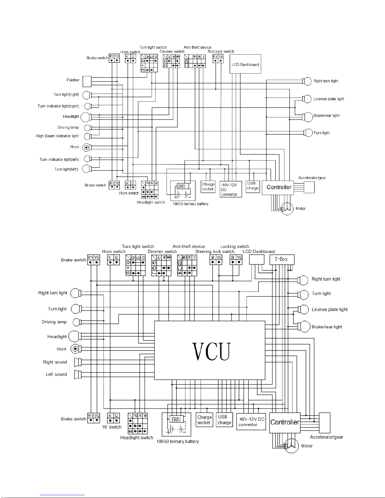
Electrical schematic diagram
iTango-C
iTango-H
Page 25
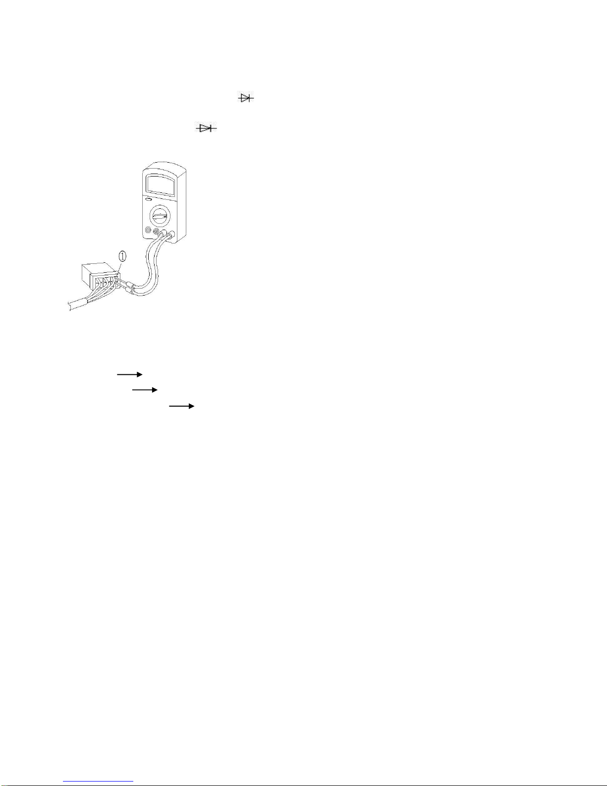
Access inspection of plug-in
Use the multimeter to check the access of each plug-in. If the access value is incorrect, check the wiring connection and replace the
plug-in as needed.
Attention
⚫ Do not insert the meter bar into the wireless terminal end of the connector. The bar must be inserted into the wired
terminal end of the connector①, when inserting, be careful not to loosen or damage the wiring.
⚫ To set the multimeter to or or "Ω" before checking the access,
⚫ Switch back and forth several times between switch positions when checking the path,
Check each switch whether it is damaged or wear, or the connection is correct and the access whether access is normal for
connectors. Details refer to "Access inspection of plug-in".
Damage/Wear repair or replace
Wrong connection correct connection
Access is poor connection replace the plug in
Page 26
Faults phenomena and maintenance methods
Faults phenomena: No power supply
①No power of battery:
A. Press the button on the battery indicator to observe if the indicator light is lighted or not, the red light is means lowest power, the
red light flashing is means that the battery has been run out.
B. Use the wire to connect between the positive pole of the battery and the K-⑧ pin of the battery to measure the voltage should be
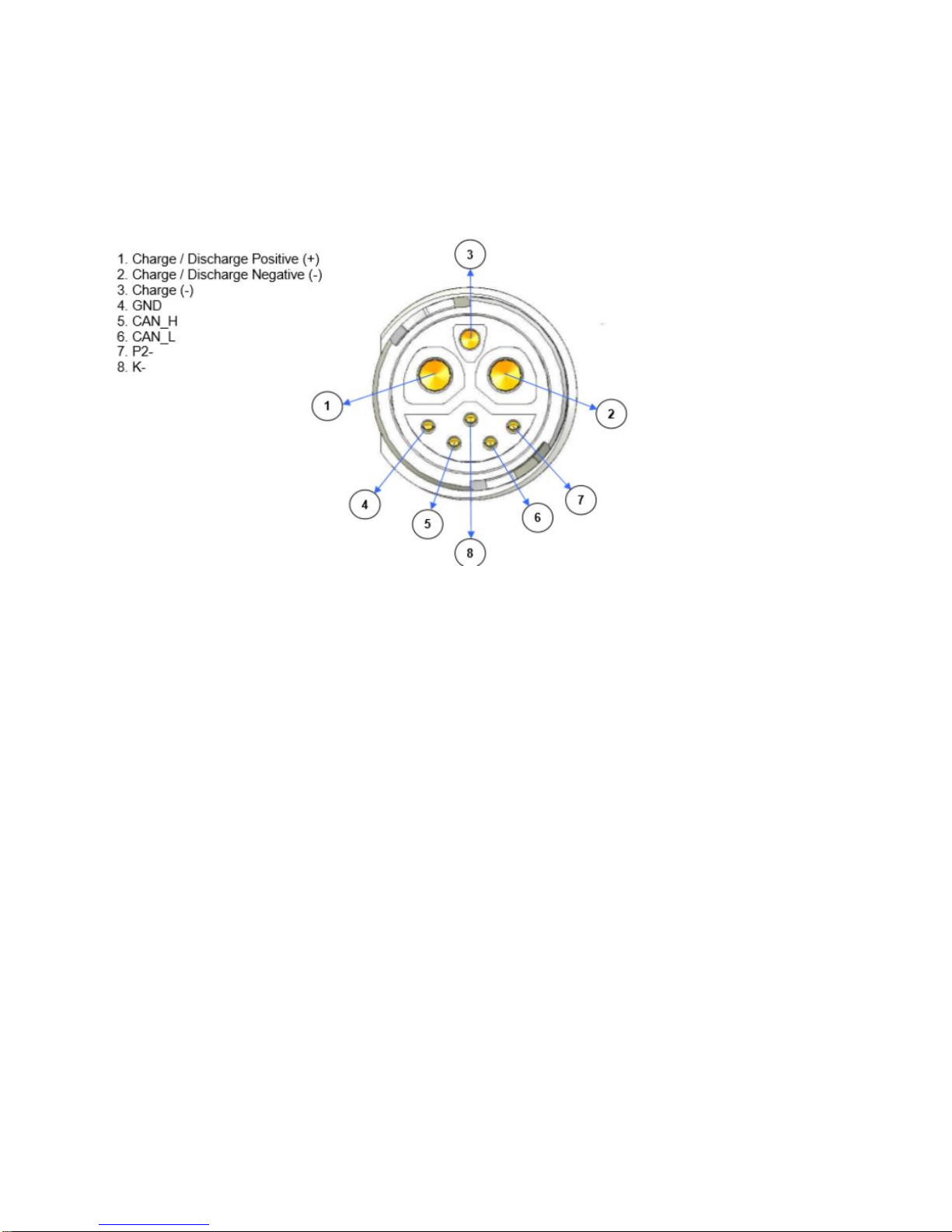
higher than 50V for positive pole① of the battery and the voltage of the negative pole ② with the multimeter to 200V DC voltage
section, otherwise the battery is out of power, you need to charge the battery, the following is the interface diagram of battery output:
C. If the battery is fully charged, follow and b steps to test, if the battery voltage is still low, you need to repair and replacement
because of the battery is break down.
② battery has power, but no power supply after connected to the vehicle
A. If the battery has power, connected to the vehicle battery plug, open the ignition lock; if the vehicle is no power, you should the
battery plug is reliable connected, re-connect and confirm again.
B. if confirmed the battery is connected with the vehicle, and open the ignition lock, the vehicle is still no power. measure the positive
and negative of charging port whether there is power(voltage same as the battery port);To measure the voltage of positive pole ①
and negative ③ pole whether it is same as the battery port with 200V DC voltage by multimeter after open the ignition lock.
C. If the voltage is too low or no voltage, it means the battery didn’t normal output, to check the fuse on the vehicle of 70A and 5A
whether its fusing (to disconnect the battery first), 5A fuse is below the seat and in the cover of controller, need to open the cover to
check; if the 70A fuse is fusing, need to check whether the controller is burnout, if 5A fuse is fusing, then need to check whether the
DC converter is burnout.
⑴Method of measuring controller
Make sure that the battery is disconnected from the battery plug, open the cover of line ball of the controller, adjust the multimeter to
buzzer, and check whether the positive and negative terminals of the controller is conduction state (interchange red and black probe
to test) ,If conduction state, the controller is burnout, if not, need to check whether it is conduction state between the positive or
negative pole of the controller and the motor phase line(interchange red and black probe to test), the controller is burnout and need
to replace if conduction state.
⑵ Method of measuring the DC converter
As with the method of measuring controller, remove the vehicle headlamp parts and converter plug, measure the converter red line
and green line or black line if its turned on, if conducted, it means that the converter has burned, they need to be replaced.
D. When the fault is identified, after confirmed unnecessary fault or replacement, turn on the battery and open ignition lock again to
confirm if the vehicle is normal, test the voltage of vehicle charging port whether its normal or not.
E. If the fuse is not blown, Check,whether the ignition lock is burned, remove the vehicle headlamp parts, unplug the ignition lock
Page 27

plug and transfer the multimeter to the buzzer. When the ignition lock is in the open state, the measurement of electricity if the red
line and the black line of the ignition lock are "ON", if it does not pass, it means that the lock is burned and needs to be replaced.
③ DC converter burnout
A. The battery output is normal, the speed meter, light or speaker does not work, the vehicle does not have forward gear and can not
move forward, only reverses gear, the DC converter is burnout, need to be replaced or repair the DC converter.
B. The battery output is normal, the speed meter, light or speaker do not work, but the vehicle can run normally, it means the DC
converter is burnout, they need to be replaced or repaired.
④ Speed meter burnout
A. Speed meter does not work (the screen does not light), the vehicle can be normal driving, lights and speakers are normal, the
speed meter is burnout, need to replace.
B. Speed meter working (screen is lighted), but no gear and power display, no speed show while the vehicle is running, to check
whether the VCU is working or not
⑴ if the VCU power supply is normal:
VCU and anti-theft device share same power supply, turn off the ignition lock at this time, to press the key of lock, unlock or searching
with the remote control, whether it can be worked properly, if yes, it is means that power supply is normal, and go ahead for next step
⑵ disconnect the battery more than 2 minutes, then connect the battery, open the ignition lock to observe whether the speed meter
is normal, if the speed meter shows normal, it means VCU is abnormal, contact the service supporter to upgrade the VCU software
by remote control.
⑶ If you disconnect the battery and still abnormal, check whether the connector is well connected and reliable for VCU and speed
meter, the battery plug whether is well inserted, and reinsert.
⑷ Check whether the communication of speed meter is burnout, if burnout, you need to replace it.
Chart of indicator flashing of LED on the Controller
Times of LED
flashing
Fault type Fault description
solution
1
Over voltage
protection
The input voltage is too high after
checked by controller
① Please use the battery supplied by our company
② The controller is faulty and need to be replaced
2
Undervoltage
protection
The input voltage is too low after
checked by controller
① charge the battery to ensure that the battery is
normal
② To check whether the wiring of the controller is
normal connected.
③ The controller is abnormal and the controller need
to be replaced
3
Over current
protection
The phase line of the motor is short
circuit or it is short circuit between the
phase line and power supply
① Check,whether the motor is normal, or, replace
the motor
② Check, whether the controller is burnout, or
replace the controller
4
Locked-rotor
protection
Motor is locked-rotor, couldn’t running
well.
The battery load is too large or uphill, the motor can
not running properly
5
Hall protection
Motor HALL input is abnormal
① Check,whether it is well connected for the motor
HALL plug-in and controller.
② Check,whether the motor Hall is burnout, replace
the motor
6
Power tube
protection
Power tube self-inspection is
abnormal
Turn off the ignition lock and disconnect the battery
plug to confirm, then to replace the controller
Page 28

Fault phenomenon: Turn on the ignition lock, turn the accelerator handlebar, but the motor does not rotate.
Fault reasons and solutions:
① The battery voltage is too low, the controller is under voltage protection: To charge the battery;
② Return of accelerator cable box is not well done: Check whether the accelerator cable is out of the accelerator cable box, need to
install properly
③ Accelerator cable box is damaged: replace the accelerator cable box;
④ Brake switch is not turn off: Check whether the return of brake handle is normal or brake power-off switch is defect, the brake light
does not lighted when you should not pull the brake handle or lift up the stander, you need to repair or replace the brake switch;
⑤ power-off switch of stander did not disconnect: lift up the stander, brake lights are bright, it need to be maintenance or replacement
of stander power-off switch;
⑥ Bad connection between Motor Hall connector and controller: unplug the connector of motor Hall and well re-plug.
⑦ Motor Hall Burnout: Repair motor Hall or replace motor
⑧ Controller burnout: repair or replace the controller
Fault phenomenon: Range is short after the battery is fully charged.
Fault reasons and solutions:
① battery burn-in: replace or repair the battery;
② Lower tire pressure: Need to tire inflation (with standard pressure value)
③ brake disc is attrition by disc brake :disc brake maintenance;
④ Charger fault, the battery can not be fully charged: replace or repair the charger.
7
Phase loss
protection
One of the phase line of motor is
disconnected.
① Check whether it is well connected for the phase
line of motor and controller.
② if the controller is burnout, replace a new one
9
Brake state
The controller is braking state
① Check whether return of brake handle is normal
and brake switch is burnout, replace if necessary.
② Check whether return of switch of side stander is
normal and side stander power-off switch is burnout,
replace if necessary.
10
Self-inspection error
protection
Abnormal when power of self-test of
controller
Close the ignition lock and disconnect the battery
plug to confirm and replace the controller
11
Overheat protection
Controller overheat
When the vehicle is running, the temperature of
controller is too high, need to stop vehicles for a
period of time, until the temperature of controller is
normal, then, the vehicle can running again.
14
Accelerator
handlebar
protection
Accelerator handlebar fault
Check whether accelerator handle bar is return or
burnout, if burnout, replace a new one.
15
Anti-theft state
controller is under the state of
anti-theft
① Press the unlock button with remote controller
② Check, whether the anti-theft device is
damaged ,and replaced if necessary
Page 29

Fault phenomenon: The battery is short charging time.
Fault reasons and solutions:
① Charger fault: battery can not be fully charged: replace or repair the charger;
② battery socket burn-in, poor contact: repair or replace the battery.
Fault phenomenon: The green light of changer always bright, lights of charger is not bright or fans doesn’t rotate when
charging after plug is well connected.
Fault reasons and solutions:
① Pay attention to the connection sequence for charger and battery: first to connect the charger output plug and battery, and connect
the regular electricity with the charger plug;
② the battery temperature is lower than 0℃or higher than 50 ℃: waiting for the battery temperature is higher than 3 ℃ or less than
45 ℃;
③ Poor connection for charging plug and socket: Unplug the charging plug, re-plug, observe the charging status, or replace the
battery;
④ Charger and battery connection is good, the indicator does not light: replace or repair the charger;
⑤ The fan of charger does not rotate during charging: replace or repair the charger.
Fault phenomenon: the electric quantity of battery is not accurate, even fully charged, the display is still less than 100% with large
deviation for electric quantity.
Fault reasons and solutions:
Full charge/discharge of the battery: drive the vehicle until the battery with no electricity and couldn’t ride any more, full charged the
battery and drive again. Redo it with two times, if there is no improvement, you need to replace or repair the battery
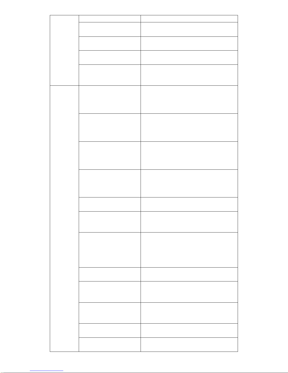
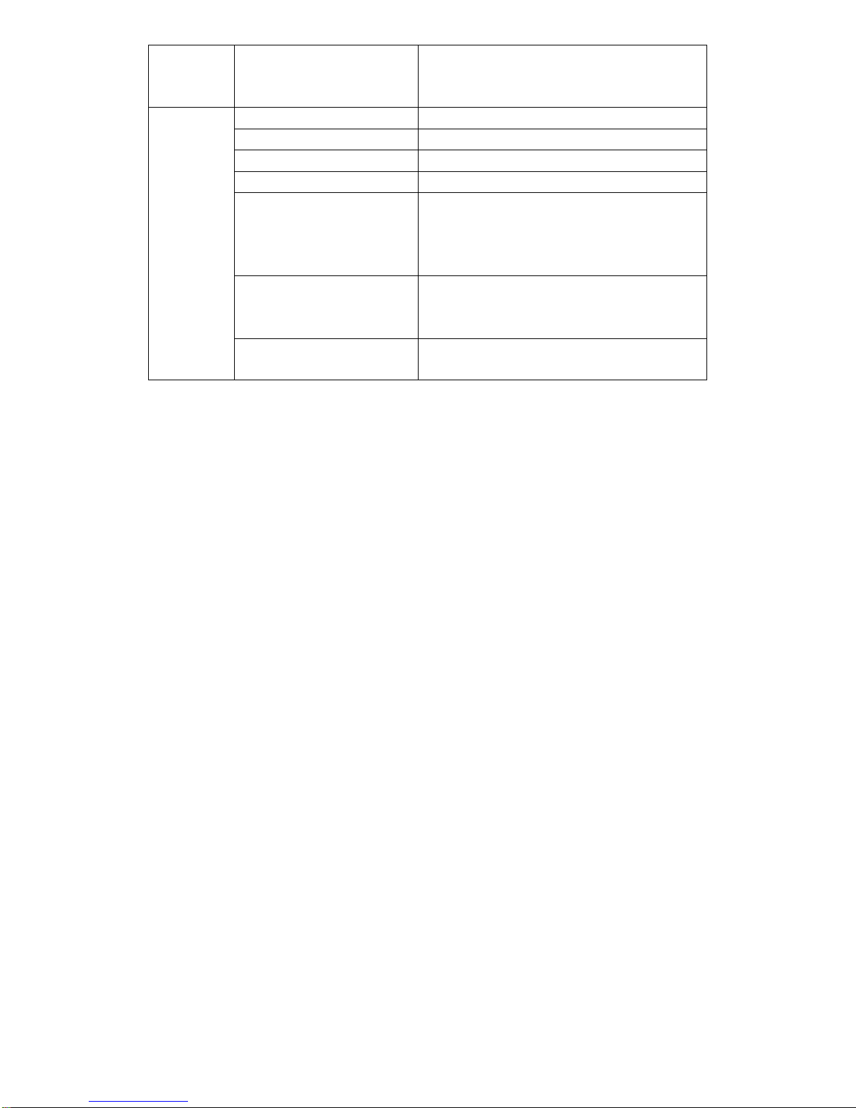
Fault phenomenon: When the symbol as "wrench" on the dashboard, please use APP to enter the "vehicle situation" page to
self-inspection. To analyze the abnormalities based on the inspection report after self-inspection:
System
category
Trouble
solution
Power
system
Power tube of Controller
Check the controller, to repair or replace
Power supply of Controller
Check the controller, to repair or replace
Over current of Controller
① Overload, working current is too large, tire
pressure is insufficient
② Check the controller and motor to repair or
replace
The controller voltage is too
high or too low
Please use the original battery supplied by our
company, To check whether the voltage of battery
and controller is normal, if not, repair or replace.
Controller overheat protection
The controller temperature is too high, let the vehicle
to stop for a while, waiting for the controller and
motor temperature to decrease
Motor phase line
① To check whether the motor phase line and the
controller is well connected, the motor phase line
without any sign of damage or fracture , replace or
repair the motor
Motor Hall
① To check whether the motor hall connector is
connected to the controller
Page 30
② Motor Hall is defects, replace or repair the motor
Under voltage protection
Battery voltage is too low, charge the battery.
Locked-rotor protection
Overload or the motor is burnout, to repair or
replace the motor
Accelerator handle
To check whether the accelerator cable box is
damaged, and replace it
The handle bar is not return
when power on.
To check whether it is return of the accelerator cable
box, and repair.
Power supply
system
Charging overheat protection
The battery temperature is higher than 50 ℃, charge
is not available; to normal charge after remove the
battery to indoor and battery temperature is below to
45 ℃.
Protection of Charging
temperature too low
The battery temperature is below 0 ℃, charge is not
available. To normal charge after remove the battery
into indoor and battery temperature is higher than
3 ℃.
Discharge overheat protection
The battery temperature is higher than 65 ℃, it is
not available for discharging , when the battery
temperature is below 60 ℃, it is available for normal
discharging.
Protection of discharge
temperature too low protection.
The battery temperature is below -20 ℃, it is not
available for discharging, when the battery
temperature higher than -10 ℃, it is available for
normal discharging.
Loose connection protection
Re-plug the battery plug, if not normal, repair or
replace
Battery high voltage protection
The total voltage of the battery is too high, the
charging voltage is too high, check the charger, to
repair or replace
MOSFET overheat
①MOSFET temperature is higher than 115 ℃, need
to disconnect the battery plug in order to down the
MOSFET temperature battery to below 80 ℃
② Check whether VCU or anti-theft power supply is
normal, repair or replace
Over voltage protection of
battery cells
The battery's single-cell voltage is too high, check
the battery and charger, repair or replacement
Battery Pack Low Voltage
Protection
The total voltage of the battery is too low, battery
charging or repair and replace it
Low voltage protection of
battery cells
The battery's single-cell voltage is too low, battery
charging or repair and replace it
Charge over current protection
The battery charge current ≥ 26A, Check whether
the charger is burnout, repair or replace.
Discharge over current
protection
The battery discharge current ≥ 75A, Check whether
the controller is burnout, repair or replace
Page 31
Short circuit protection
Check the vehicle circuit whether there is the
phenomenon of short circuit, to repair or replace it if
short circuit.
Vehicles
Central
control
system(VCU)
GPS Fault
VCU internal faults, maintenance and replacement
GPRS Fault
VCU internal faults, maintenance and replacement
Gyro Fault
VCU internal faults, maintenance and replacement
Abnormal power
VCU internal faults, maintenance and replacement
Communication with the
controller is abnormal
Check the communication between controller and
VCU, then to repair and replace.
Communication with the BMS is
abnormal
Check the communication between the battery and
VCU, then to repair and replace
Communication with the
dashboard is abnormal
Check the communication between the dashboard
and VCU, then to repair and replace
Page 32
 Loading...