

Page 1
User manual
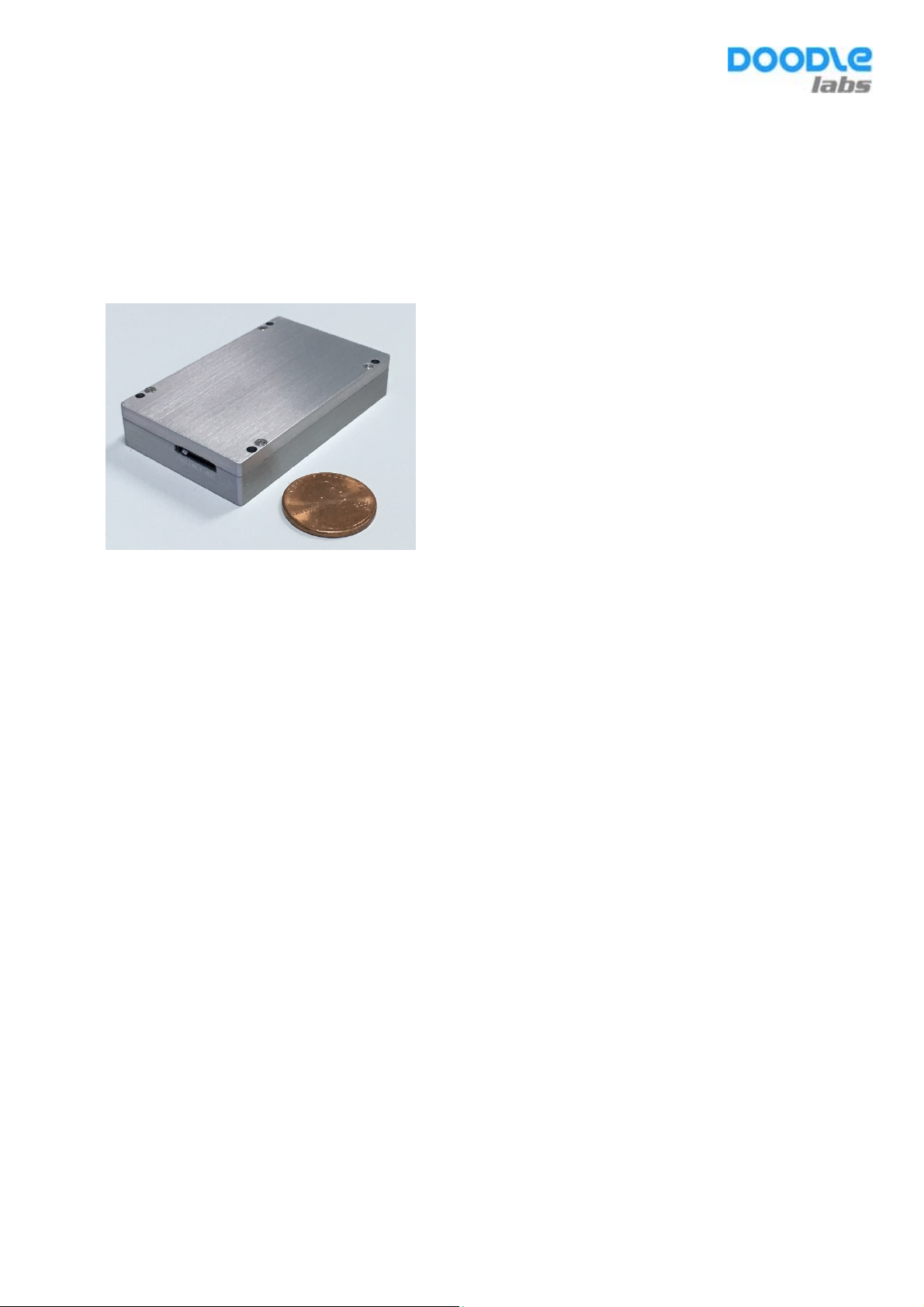
Model: RM-915-2H
900 MHz, Rugged, Long Range 2 Stream Broadband Radio Transceiver
Features
• Very low size, weight, and power (SWaP) for mobile applications
• 37x68x11 mm, 70 grams (2 stream)
• Available in frequency bands up to 6 GHz
• Configurable channel size from 3~40 MHz
• Dynamic Link adaptation to optimize throughput depending on channel conditions
• Adaptive radio modulations from DSSS up to 64QAM
• High Tx power for long range (adjustable up to 1W)
• Up to 50 Mbps Iperf throughput
• Ethernet interface to allow easy integration into various applications
• Point-to-Point, Point-to-Multipoint, and Adhoc operating modes
• Mobile mesh router (Optional)
• High wireless data security with up to 128 bit AES encryption
• OTA firmware upgrade
• Industrial temperature range (-40C to +85C)
• COTS – Commercial off the Shelf
Target Applications
• Unmanned Aerial Vehicles (Drones)
• Mobile robotics
• Mines and Construction site machines
• Public Safety/Video surveillance
• Private Networks in Oil and gas fields
• Wind Turbine and Solar farms
• Wireless ethernet extensions
Page 2
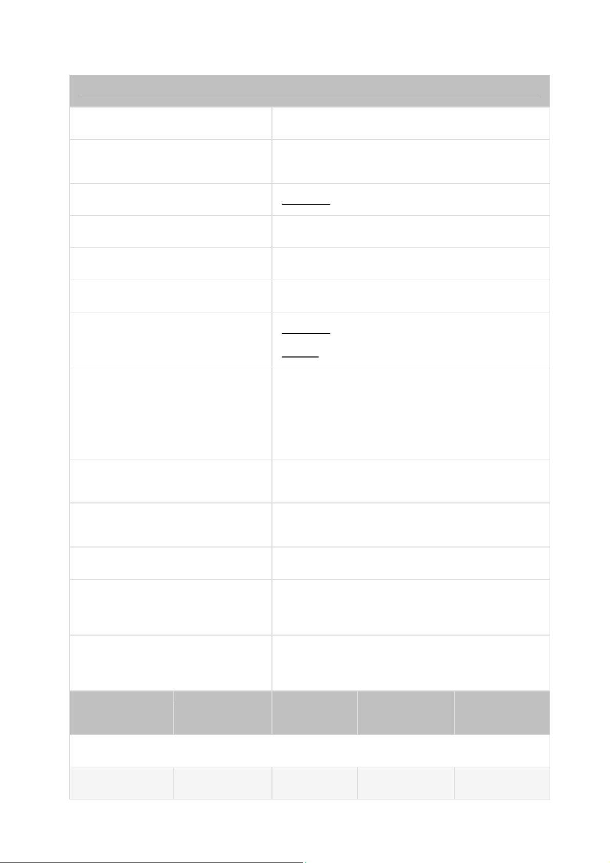
TECHNICAL SPECIFICATIONS
Model No. RM-915-2H (Rugged, Long Range applications
Qualcomm Atheros
Chipset
Software Support OpenWRT (Wireless Router/Linux OS)
Center Frequency Range 902 MHz ~ 928 MHz
Channel Bandwidth* 5 MHz
Radio Modulation (Auto Adjust) CCK, BPSK, QPSK, 16 QAM, and 64 QAM
QCA4531 with Extended Temperature range
802.11 b/g: 1, 2, 5.5, 6, 9, 11, 12, 18, 24, 36, 48 and 54
Mbps (2.4 GHz)
Data Rates Supported
802.11n version 2.0 Capabilities
Operating Modes
MAC Protocol
Wireless Error Correction FEC, ARQ
Wireless Data Security
802.11n: MCS0-15
Packet aggregation: A-MPDU (Tx/Rx), A-MSDU (Tx/Rx),
Maximal ratio combining (MRC), Cyclic shift diversity
(CSD), Frame aggregation, block ACK, 802.11e
compatible bursting, Spatial multiplexing, cyclic-delay
diversity (CDD), low-density parity check (LDPC), Space
Time Block Code (STBC)
AP, STA and Adhoc modes to implement Point to Point,
Point to multi Point, and Mesh networks
TDD with Carrier Sense Multiple Access with Collision
Avoidance (CSMA/CA)
128 bit AES, WEP, TKIP and WAPI hardware
encryption. Support for IEEE 802.11d, e, h, i, k, r, v, w
and time stamp standards
FIPS Certification
Tx/Rx
Specification
5 MHz Channel
802.11n BPSK 1/2 30 -98
Radio
Modulation
Loop back mode to facilitate FIPS AES certification,
Small packet size (96 bytes) in AES encryption at full
packet rate
Coding Rate
Tx Power
(±2dBm)**
Rx Sensitivity
(Typ)
Page 3

802.11n 16 QAM 3/4 30 -89
802.11n 64 QAM 3/4 24 -82
* It is advantageous to use the smallest Channel Bandwidth that can support the Throughput
requirements. Smaller bandwidths provide more channels to choose and help avoid interference
issues. The system’s SNR is higher at smaller Channel Bandwidths and Range is longer.
Antenna Signal Strength
Receiver LNA Gain >10 dB
Receive chain Noise Figure 6 dB
RF Power control by Driver
RF Hardware Disable (RF Kill)
Control for External Power Amp Available as an optional configuration
Receiver Adjacent Channel Rejection
(ACR)
Receiver Alternate Channel Rejection
(ALCR) >35 dB @ 11a, 6 Mbps (Typ)
-35 to -85 dBm (Recommended), Absolute
Maximum=+12 dBm
In 0.5 dBm steps. Accuracy of power calibration loop ±2
dBm. Each transceiver individually calibrated and
tested.
Pin 20 of miniPCI-E interface. (Required for FAA
compliance)
>18 dB @ 11a, 6 Mbps (Typ)
Transmitter Adjacent Channel Leakage
power Ratio (ACLR) 45 dB (Fc ± ChBW)
Transmitter Spurious Emission
Suppression
PHYSICAL, ENVIRONMENTAL AND OTHER SPECIFICATIONS
Antenna Ports 2 Ports (50 Ohms) with MMCX connectors
Integrated Antenna Port Protection >20 KV (Human Body Model)
Host Interface 100Base-T Ethernet
Host CPU Board Any CPU board with Industry standard miniPCI-Express
-40 dBc
Page 4

interface with minimum 6 mm connector height
Operating Voltage 5~42 V
9.0W in data transfer mode
Power Consumption
Shield case temperature range
(Operating)
Cable Assembly Assembly drawing available upon request.
Dimensions
3.3W in data receive mode
-40°C to +85°C (Rugged, Long range RM-915-1G
model)
The System’s thermal design should ensure that the
transceiver’s shield case temperature is maintained
within these specifications.
68 x 57 x 11.5 mm
70 grams
Mechanical drawing and 3D-CAD files available upon
request
Humidity (Operating) 0% – 95% (Non-condensing)
Designed and Verified to meet various regulatory
requirements. Formal testing and approval is required
based on the System Integrator’s particular host platform
and antenna type. The System Integrator is also
responsible for obtaining all required regulatory
approvals in target markets for the finished product.
Doodle Labs can offer assistance for compliance testing
Regulatory Requirements
RoHS/WEEE Compliance Yes. 100% Recyclable/Biodegradable packaging
* Specifications are subject to change without prior notice.
of the System Integrator’s host platform.
Page 5

FCCRadiationExposureStatement
The antenna(s) used for this transmitter must be installed to provide a separation distance of at least 20
cm from all persons and must not be collocated or operating in conjunction with any other antenna or
transmitter, except in accordance with FCC multi-transmitter product procedures.
Radiation Exposure Statement:
This equipment complies with FCC radiation exposure limits set forth for an uncontrolled environment.
This transmitter must not be co-located or operating in conjunction with any other antenna or transmitter.
The availability of some specific channels and/or operational frequency bands are country dep endent
and are firmware programmed at the factory to match the intended destination. The firmware setting is
not accessible by the end user.
The final end product must be labelled in a visible area with the following: “Contains Transmitter
Module 2AG87RM-915-2H” In the event that these conditions can not be met (for example certain
laptop configurations or co-location with another transmitter), then the FCC authorization is no longer
considered valid and the FCC ID can not be used on the final product. In these circumstances, the OEM
integrator will be responsible for re-evaluating the end product (including the tran smitter) and obtaining
a separate FCC authorization.
The Innovation, Science and Economic Development Canada certification label of a module shall be
clearly visible at all times when installed in the host product; otherwise, the host product must be
labelled to display the Innovation, Science and Economic Development Canada certification number for
the module, preceded by the word “Contains” or similar wording expressing the same meaning, as
follows: Contains IC: 21411-RM9152H.
IC Statement
This device complies with Industry Canada’s licence-exempt RSSs. Operation is subject to the following
two conditions:
(1) This device may not cause interference; and
(2) This device must accept any interference, including interference that may cause undesired
operation of the device.
The term “IC: “ before the certification/registration number only signifies that the Industry Canada
technical specifications were met. This product meets the applicable Industry Canada technical
specifications.
Le présent appareil est conforme aux CNR d'Industrie Canada applicable aux appareils radio exempts
de licence. L'exploitation est autorisée aux deux conditions suivantes : (1) l'appareil ne doit pas produire
de brouillage, et (2) l'utilisateur de l'appareil doit accepter tout brouillage radioélectrique subi, même si
le brouillage est susceptible d'en compromettre le fonctionnement
Singapore: USA:
Doodle Labs (SG) Pte. Ltd. Doodle Labs LLC
150 Kampong Ampat 2 Mattawang Drive
KA Center, Suite 05-03 Somerset, NJ 08873
Singapore 368324 Tel: +1 862 345 6781
Tel: +65 6253 0100 Fax: +65 6353 5564
 Loading...