

User Manual
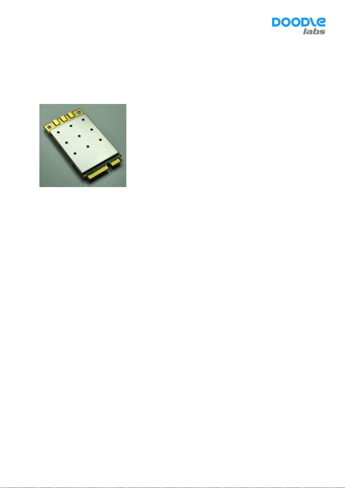
ACM-DB-3
Rugged/Military grade 2.4/5 GHz 3x3 MIMO Wi-Fi® Radio Transceivers
Features
Qualcomm-Atheros QCA9890-BR4B Chipset with Extended Temperature Range
Up to 1.3 Gbps Throughput with 3x3 MIMO Technology
Calibrated High Power 2.4 GHz (29 dBm) and 5 GHz operation (27 dBm) for Extended Range
Supported by OpenWRT and Ath10k Open-Source Driver
MiniPCIE Interface

Installation and Usage
The ACM-DB-3 has been FCC certified for indoor usage with Superbat 3-dBi rubber-duck antennas (WA2-1321-
S02SP1-030 in the 5-GHz bands, and WA2-995-S02SP1-030 antennas in the 2.4GHz band). The ACM-DB-3 mates
with a standard PCIE-mini slot and integrates with the Ath10k software driver which is pre-installed in Linuxbased systems.

TECHNICAL SPECIFICATIONS
Model No. ACM-DB-3 (Rugged/Military Applications, 802.11ac)
MAC Chipset QCA9890-BR4B with Extended Temperature range for Outdoor and Rugged models)
Open Source Linux Driver
Software Support
ath10k
OpenWRT (Wireless Router/Linux OS)
Center Frequency Range
Channel Bandwidth/(No. of
Non-overlapping Channels)*
Radio Modulation (Auto Adjust)
Data Rates Supported
802.11ac Wave 1 Capabilities
Operating Modes
MAC Protocol TDD with Carrier Sense Multiple Access with Collision Avoidance (CSMA/CA)
Wireless Error Correction FEC, ARQ
Wireless Data Security
FIPS Certification
Tx/Rx Specification Data Rate
5 GHz (20 MHz Channel)
802.11a, Single Stream, STBC 6 Mbps BPSK 5.5 23.89 -98
802.11a, Single Stream, STBC 24 Mbps 16 QAM 19 23.89 -89
802.11a, Single Stream, STBC 36 Mbps 16 QAM 25 23.89 -87
802.11a, Single Stream, STBC 48 Mbps 64 QAM 29 23.89 -85
802.11a, Single Stream, STBC 54 Mbps 64 QAM 33 23.89 -83
802.11ac, VHT20, 3 Streams MCS0 BPSK 18 23.97 -93
802.11ac, VHT20, 3 Streams MCS2 QPSK 54 23.97 -89
802.11ac, VHT20, 3 Streams MCS4 16 QAM 106 23.97 -82
802.11ac, VHT20, 3 Streams MCS7 64 QAM 171 23.97 -74
5.180 GHz -5.240 Ghz & 5.745 GHz -5.825 Ghz
2.412 GHz ~ 2.484 GHz
This varies by the regulatory domain
20/(9), 40/(4) and 80/(2) MHz channels (5.x GHz)
20/(3), and 40/(1) MHz channels (2.4 GHz)
BPSK, QPSK, 16 QAM, 64 QAM and 256 QAM (5.x GHz – 11ac models)
CCK, BPSK, QPSK, 16 QAM, 64 QAM and 256 QAM (2.4 GHz – 11ac models)
802.11ac
802.11a
802.11n
802.11b/g
●802.11ac Beam Forming
●Packet aggregation: A-MPDU (Tx/Rx), A-MSDU (Tx/Rx), Maximal ratio combining
(MRC), Cyclic shift diversity (CSD), Frame aggregation, block ACK, 802.11e compatible
bursting, Spatial multiplexing, cyclic-delay diversity (CDD), low-density parity check
(LDPC), Space Time Block Code (STBC)
●Phy data rates up to 1.3 Gbps (80 MHz channel)
AP, STA and Adhoc modes to implement Point to Point, Point to multi Point, and Mesh
networks
128 bit AES, WEP, TKIP and WAPI hardware encryption. Support for IEEE 802.11d, e, h, i,
k, r, v, w and time stamp standards
Loop back mode to facilitate FIPS AES certification, Small packet size (96 bytes) in AES
encryption at full packet rate
: MCS0-9 (5.x GHz)
: 6, 9, 12, 18, 24, 36, 48 and 54 Mbps (5.x GHz)
: MCS0-23 (5.x and 2.4 GHz)
: 1, 2, 5.5, 6, 9, 11, 12, 18, 24, 36, 48 and 54 Mbps (2.4 GHz)
Radio
Modulation
Throughput**
Mbps
(Cabled Test
Setup)
Max Tx Power
3 Antennas
Rx Sensitivity
(± 2 dBm)
3 Antennas
802.11ac, VHT20, 3 Streams MCS8 256 QAM 201 23.97 -70
5 GHz (40 MHz Channel)
802.11ac, VHT40, 3 Streams MCS0 BPSK 37 23.99 -90
802.11ac, VHT40, 3 Streams MCS2 QPSK 110 23.99 -82
802.11ac, VHT40, 3 Streams MCS4 16 QAM 210 23.99 -78
802.11ac, VHT40, 3 Streams MCS7 64 QAM 331 23.99 -71

802.11ac, VHT40, 3 Streams MCS8 256 QAM 405 23.99 -68
802.11ac, VHT40, 3 Streams MCS9 256 QAM 429 23.99 -66
5 GHz (80 MHz Channel)
802.11ac, VHT80, 3 Streams MCS0 BPSK 76 23.69 -87
802.11ac, VHT80, 3 Streams MCS2 QPSK 223 23.69 -81
802.11ac, VHT80, 3 Streams MCS4 16 QAM 404 23.69 -72
802.11ac, VHT80, 3 Streams MCS7 64 QAM 622 23.69 -66
802.11ac, VHT80, 3 Streams MCS8 256 QAM 686 23.69 -64
802.11ac, VHT80, 3 Streams MCS9 256 QAM 789 23.69 -62
2.4 GHz (20 MHz Channel)
802.11b, Single Stream, STBC 1 Mbps CCK 0.8 26.43 -100
802.11g, Single Stream, STBC 6 Mbps BPSK 5.5 26.07 -98
802.11g, Single Stream, STBC 24 Mbps 16 QAM 18 26.07 -90
802.11g, Single Stream, STBC 36 Mbps 16 QAM 24 26.07 -87
802.11g, Single Stream, STBC 48 Mbps 64 QAM 31 26.07 -84
802.11g, Single Stream, STBC 54 Mbps 64 QAM 32 26.07 -82
802.11n, HT20, 3 Streams MCS16 BPSK 18 26.26 -92
802.11n, HT20, 3 Streams MCS18 QPSK 54 26.26 -86
802.11n, HT20, 3 Streams MCS20 16QAM 108 26.26 -79
802.11n, HT20, 3 Streams MCS22 64 QAM 162 26.26 -75
802.11n, HT20, 3 Streams MCS23 64QAM 189 26.26 -74
2.4 GHz (40 MHz Channel)
802.11n, HT40, 3 Streams MCS16 BPSK 36 25.87 -87
802.11n, HT40, 3 Streams MCS18 QPSK 108 25.87 -80
802.11n, HT40, 3 Streams MCS20 16QAM 216 25.87 -74
802.11n, HT40, 3 Streams MCS22 64 QAM 470 25.87 -70
802.11n, HT40, 3 Streams MCS23 64QAM 486 25.87 -68
* It is advantageous to use the smallest Channel Bandwidth that can support the Throughput requirements. Smaller
Bandwidths provide more channels to choose and help avoid interference issues. The system’s SNR is higher at smaller
Channel Bandwidths and Range is longer.
** Throughput of a wireless link depends on many environmental parameters. Here the bench measurement results are shown
to give an indication of the real life performance of Doodle Labs modules. These results are lower than the theoretical values
published in most of the literature. They do not include distance related derating.
Antenna Signal Strength -50 to -90 dBm (Recommended), Absolute Maximum=+12 dBm
Antenna port isolation for
concurrent operation
Integrated Antenna Port
Protection
Receiver LNA Gain >12 dB
Receiver Adjacent Channel
Rejection (ACR)
Receiver Next to Adjacent
Channel Rejection (ALCR)
Receive chain Noise Figure +5 dB
Transmitter Adjacent Channel
Leakage power Ratio (ACLR)
Transmitter Spurious Emission -40 dBc (Minimum)
Up to +10 dBm signal strength for 5 GHz signal without degrading 2.4 GHz operation
Up to +5 dBm signal strength for 2.4 GHz signal without degrading 5.x GHz operation
>12 KV (Human Body Model) for Outdoor and Rugged models (ACO/ACM-DB-3 and
NO/NM-DB-3)
>28 dB @6 Mbps, 13 dB @54 Mbps, 3 dB @ VHT80, MCS9
>40 dB
Min 45 dB (Fc ± ChBW)

Suppression
RF Power control by Driver In 0.5 dBm steps. Accuracy of power calibration ±2 dBm
RF Hardware Disable Pin 20 of miniPCI-E interface. (Required for FAA compliance)
Control for External Power Amp Available as an optional configuration
Spectral Analysis 8 bit resolution spectral FFTs available for software analysis
PHYSICAL, ENVIRONMENTAL AND OTHER SPECIFICATIONS
Antenna Ports
Host Interface miniPCI-Express 1.2 Standard
Host CPU Board
Operating Voltage 3.3 Volts from miniPCI-Express connector
Power Consumption
Shield case temperature range
(Operating)
Humidity (Operating) 0% – 95% (Non-condensing)
Dimensions
Regulatory Requirements
FCC ID 2AG87DLM168N
CE/ETSI
Industry Canada (IC) Q1 2016
RoHS/WEEE Compliance Yes. 100% Recyclable/Biodegradable packaging
3 Ports (50 Ohms) with MMCX connectors.
Optional configuration with U.FL connectors available on request
Any CPU board with Industry standard miniPCI-Express interface with minimum 6 mm
connector height
5W @ Max power, in continuous data transfer mode on all 3 chains
3.5W @ 25 dBm power, in continuous data transfer mode on all 3 chains
2.5W @ 20 dBm power (ETSI max), in continuous data transfer mode on all 3 chains
0.9W in continuous data receive mode
250 mW in Sleep mode
0°C to +60°C (Enterprise/Indoor “*E-DB-3” models)
-40°C to +60°C (Outdoor “*O-DB-3” models)
-40°C to +80°C (Rugged “*M-DB-3” models)
The System’s thermal design should ensure that the transceiver’s case temperature is
maintained within these specifications.
30 x 50 x 7 mm, 14 grams (Rugged models).
Mechanical drawing and 3D-CAD files available upon request
Designed and Verified to meet various regulatory requirements. Formal testing and
approval is required based on the Integrator’s particular host platform and antenna type.
The Integrator is also responsible for obtaining all required regulatory approvals in target
markets for the finished product.
11ac models in AP and Client modes with full DFS – in conformity with all the requirements
of the European Directive 1999/5/EC – EN 301 893 V1.8.1, EN 300 328 V.1.8.1, EN 301
489-1 V1.9.2, EN 301 489-17 V2.2.1, EN 60950-1:2006 + A11:2009 + A1:2010 +
A12:2011+ A2:2013

FCC Statement
Changes or modifications not expressly approved by the party responsible for compliance could void the user's authority to
operate the equipment.
This equipment has been tested and found to comply with the limits for a Class B digital device, pursuant to Part 15 of the FCC
Rules. These limits are designed to provide reasonable protection against harmful interference in a residential installation. This
equipment generates uses and can radiate radio frequency energy and, if not installed and used in accordance with the
instructions, may cause harmful interference to radio communications. However, there is no guarantee that interference will not
occur in a particular installation. If this equipment does cause harmful interference to radio or television reception, which can be
determined by turning the equipment off and on, the user is encouraged to try to correct the interference by one or more of the
following measures:
-- Reorient or relocate the receiving antenna.
-- Increase the separation between the equipment and receiver.
-- Connect the equipment into an outlet on a circuit different from that to which the receiver is connected.
-- Consult the dealer or an experienced radio/TV technician for help
This device complies with part 15 of the FCC rules. Operation is subject to the following two conditions (1)this device may not
cause harmful interference, and (2) this device must accept any interference received, including interference that may cause
undesired operation
Radiation Exposure Statement:
The modular can be installed or integrated in mobile or fix devices only.
This modular cannot be installed in any portable device, for example, USB dongle like transmitters is forbidden.
This equipment complies with FCC radiation exposure limits set forth for an uncontrolled environment.
This transmitter must not be collocated or operating in conjunction with any other antenna or transmitter.
The availability of some specific channels and/or operational frequency bands are country dependent and are
firmware programmed at the factory to match the intended destination.
The firmware setting is not accessible by the end user.
The antenna(s) used for this transmitter must be installed to provide a
and must not be collocated or operating in conjunction with any other antenna or transmitter, except in accordance with
FCC multi-transmitter product procedures.
If the FCC identification number is not visible when the module is installed inside another device, then the outside
of the device into which the module is installed must also display a label referring to the enclosed module.
This exterior label can use wording such as the following: “Contains Transmitter Module FCC ID:2AG87DLM168N
Or Contains FCC ID:2AG87DLM168N” when the module is installed inside another device, the user manual
of this device must contain below warning statements;
1. This device complies with Part 15 of the FCC Rules. Operation is subject to the following two conditions:
(1) This device may not cause harmful interference.
(2) This device must accept any interference received, including interference that may cause undesired operation.
2. Changes or modifications not expressly approved by the party responsible for compliance could void the
user's authority to operate the equipment.
The devices must be installed and used in strict accordance with the manufacturer's instructions as
described in the user documentation that comes with the product.
The antenna type used is the reverse screw R-SMA antenna and the max antenna gain is 3dBi.
The diagram shows how to connect the modular with its intended antenna .
separation distance of at least 20 cm from all persons
Modular
Coaxial Line
(50 )
Ω
Antenna
Singapore: USA:
Doodle Labs (SG) Pte. Ltd. Doodle Labs LLC
150 Kampong Ampat 2 Mattawang Drive
KA Center, Suite 05-03 Somerset, NJ 08873
Singapore 368324 Tel: +1 862 345 6781
Tel: +65 6253 0100 Fax: +65 6353 5564
 Loading...