


User Guide
Model : AC Drive (V.F.D)
(3-Phase input)
www.doochpump.com


[SAFETY PRECAUTIONS]
Preface
Thank you for choosing DOOCH’s high performance Q-Drive series.
The Q-Drive is a dedicated pump drive designed for variable Speed pumping system.
The Q-Drive is manufactured with high-quality components and materials and incorporate
the latest microprocessor technology available.
This manual is published for the consumers to easily operate the pump system since the
Q-drive is attached to the pump system.
Before installation and operation please peruse in this manual thoroughly.
※ The information contained in this manual is subjected to change without prior notice.
Safety Precautions
ㆍ Since the safety precautions are actions to allow using this product safely and rightly in
order to prevent possible accident or dangers from occurring, be sure to follow them.
ㆍ This user’s manual contains two kinds of marks such as ‘WARNING,’ and CAUTION.
ㆍ These marks are warning clauses against possibility of faulty use by the users.
ㆍ In order to fully understand the marks for safe procedure, please read the manual
through the end before using the equipment.
ㆍ Please keep this manual where the user of this driver can read it at any time.
Warning:
It indicates a potential dangerous situation that may cause some fault,
serious injury or death if the instruction is not being observed.
Caution:
It shows a potential dangerous situation that may cause some damage
on the product and loss of property if the instruction is not being observed.
DOOCHPUMP
1 |

[SAFETY PRECAUTIONS]
ㆍDo not open cover during powered state or operation.
(Exposed high voltage terminals or charging part of DC voltage may
cause electric shock.)
ㆍDo not open cover even when power is not supplied except for
wiring or inspection work.
(When the power is turned off, charged DC voltage in charging part
of drive may cause electric shock.)
ㆍDuring wiring work or regular inspection, cut off the power and
check with tester if DC voltage is discharged after elapsed
more than 10 minutes.
(It may cause electric shock. Execute work when charging voltage
of DC part is DC 30V or less.)
ㆍDo not operate the switch or drive with wet hands.
(It may cause electric shock.)
ㆍWhen any part of drive input or cable jacket is damaged,
do not apply electricity or operate the equipment.
(It may cause electric shock.)
ㆍDo not put over stress on the input/output power cable or
signal wires of the drive with heavy object.
(It may damage on the cable jacket to cause electric shock.)
ㆍDo not install the equipment near the inflammable materials.
(Installation on or near the inflammable materials may cause fire.)
ㆍWhen drive has any fault, cut off the input power.
(If not, it may cause fire due to consequent accident.)
ㆍDo not touch the drive during powered state or several minutes
after power is turned off.
(Since drive has high temperature after operation, body contact
may cause burn.)
ㆍDo not input power for the drive with damaged product and
part even if installation is completed.
(It may cause electric shock.)
ㆍDo not leave any damageable objects from inside of drive, such
as screw, metal, water, oil, etc.
(It may cause fire.)
DOOCHPUMP
2 |

[SAFETY PRECAUTIONS]
Cautions for Use
A. Transportation and Installation
ㆍ Transport the product with correct method according to its weight.
ㆍ Do not stack the products with more than specified layers.
ㆍ Install the product upon rules described on the User’s Manual.
ㆍ Do not open during transportation of the product.
ㆍ Do not put any heavy object on the product.
ㆍ Installation direction shall follow criteria specified on the User’s Manual.
ㆍ Do not fall or give strong impact on the drive as it is a precise instrument.
ㆍ Draw water completely out of the pump during winter without using for a long time.
ㆍ Use the drive under the environmental conditions as mentioned below .
Installation Location
Temperature/Humidity
Keep out of corrosive gasses, inflammable gasses,
Liquid and dust.
-10 ~ 40℃ / Not more than 90% RH (No dewdrop)
Storage Temperature
Elevation
Vibration
Ambient Atmospheric Pressure
-20 ~ 65℃
Altitude 1,000m or lower
below 5.9m/sec² (=0.6g)
70 ~ 106 kpa
B. Wiring
ㆍ After installing the main body, execute wiring.
ㆍ Wiring or inspection shall be performed by the professional technicians.
DOOCHPUMP
3 |

[SAFETY PRECAUTIONS]
ㆍ Do not install static condenser, radio noise filter, and so on at the output terminals of the
drive.
ㆍ Check if the power input line and motor output line are interchanged.
ㆍ Faulty terminal connection may cause damage on the drive.
ㆍ Use the circuit breaker.
※ Do not install leakage breaker at the power input.
* If you have any problems , please contact our local agent.
C. Checkup on Initial Operation
ㆍ Be sure to check setup parameters of the drive before operating it first. It may require
changing parameters according to states such as type of pump or installed system
environments.
ㆍ For terminal blocks for main power circuit and control circuit, be sure to follow connection
method and electrical specifications specified on this manual. Improper use may damage on
the drive.
ㆍ Be sure to use pressure sensors and low water level sensor specified by Dooch.
D. Operation
ㆍ Since it has automatic restart and recovery functions after power failure in default
and it is automatically restarted in case it is stopped due to fault or system alarm or power is
turned off during operation, be careful when power is applied initially.
ㆍ Do not modify or change inside of the product without approval
ㆍ Do not start or stop the drive with electronic contactor installed at the power input.
ㆍ Install EMC filters to reduce impact from electromagnetic wave in order to protect
electronic equipment being used near the drive.
ㆍ Install input reactor when input voltage is in unbalanced condition. Static condenser or
generator may be overheated and destroyed due to high frequency on power source
generated by drive.
DOOCHPUMP
4 |

[SAFETY PRECAUTIONS]
ㆍ In case of driving 400V class motor with the drive, use the motor with reinforced
insulation or conduct suppress measure against micro-surge voltage. (Motor may
be sometimes destroyed upon deteriorated its insulation performance due to
micro-surge voltage.)
ㆍ In case of initialization of parameters, set up required parameters again before
operation. Parameter initialization changes the parameter values to factory settings.
E. Reaction on Failure and Malfunction
ㆍ In case drive is destroyed to make operation impossible, reliability of pump system
may become deteriorated. It is recommended to install additional auxiliary system in
preparation of such situations.
ㆍ For countermeasure against drive failure, refer to Chapter 7
DOOCHPUMP
5 |
[SAFETY PRECAUTIONS]
6 |
DOOCHPUMP

[CONTENTS]
CONTENTS
[ Chapter 1. Basic Matters ]
1.1 Nameplate information
1.2 Type of product
1.3 Installation
1.4 Wiring
[ Chapter 2. Specification ]
2.1 Specification of Product
[ Chapter 3. External Dimension ]
3.1 NQ-0075T ~ NQ-0220T
3.2 NQ-0400T
3.3 NQ-0550T ~ NQ-0750T
3.4 NQ-1100T ~ NQ-1500T
3.5 NQ-1850T ~ NQ-2200T
[Chapter 4. Installation ]
4.1 Caution on Installation
4.2 Wiring Diagram of Terminals
4.3 Wiring of Main Power Supply Circuit
4.3.1 Description on Main Power Supply Terminals
4.3.2 Caution on Main Power Supply Wiring
4.3.3 Caution on Ground Wiring
4.3.4 Specification of Recommended Wires and Terminal Screw
4.4 Control Circuit Wiring
4.4.1 Arrangement of Control Terminal Block
4.4.2 Functions of Control Terminal Block
4.4.3 Cautions on Control Circuit Wiring
4.4.4 Connection of Pressure Sensor and Low Water Level Sensor
4.4.5 Sink Mode and Source Mode
4.4.6 Communication Line Wiring
1 |
DOOCHPUMP

[CONTENTS]
[ Chapter 5. Operation ]
5.1 FND
5.1.1 Appearance and Description of FND
5.1.2 Functional Description of each Part
5.1.3 How to change Parameter Settings
5.2 Function Setup
5.2.1 Basic Function Setup
5.2.2 Expansion Function Setup
5.3 Basic Operation
5.3.1 Constant Pressure Control Mode
[ Chapter 6. Function Table & Description]
6.1 Display of present status
6.2 Pump Control Group
6.3 Drive Control Group
6.4 Description on Function of Parameter Settings
6.4.1 Pump Control Group
6.4.2 Drive Control Group
[ Chapter 7. Cause of Fault and Reaction ]
7.1 Fault History Table
7.2 Reset of fault and alarm
7.3 Cause of Fault and Reaction
[ Chapter 8. Appendix ]
8.1 RS-485
8.2 Peripherals
8.3 EMC filter
2 |
DOOCHPUMP

[
[CHAPTER 1 BASIC MATTERS]
1. Precautions before Using
1.1 Information Nameplate
After taking drive out of the package box, check up the nameplate at the side of the body
and verify if the type, rated output and so on of the drive are matched with the ordered
product. In addition, check if there is any damage during transportation.
* If you have any question or the product has any abnormal state, please contact the
agent or A/S center of Dooch.
- Nameplate of the Product –
1.2 Type of Product
NQ- 0 7 5 0 T
Type of Drive
Input specification
Output specification
①
T : Three phase
②
It indicates capacity in 00.00kW unit.
0075 : 0.75kW(1HP)
0150 : 1.50kW(2HP)
0220 : 2.20kW(3HP)
0400 : 4.00kW(5.5HP)
0550 : 5.50kW(7.5HP)
0750 : 7.50kW(10HP)
1100 : 11kW(15HP)
1500 : 15kW(20HP)
1850 : 18.5kW(25HP)
2200 : 22kW(30HP)
1-1 |
DOOCHPUMP

[
[CHAPTER 1 BASIC MATTERS]
ㆍ Product model name is indicated as above. Initial four digits indicate driving
capacity of the drive in 00.00kW unit. Decimal point is not indicated.
ㆍ 'T' refers Three phase.
ㆍ ‘D’ means CAN Driver indicating Multi-Drive control system. If it is a single type, D will
be omitted.
1.3 Installation
Install the drive with proper method under specified conditions considering its
life and performance.
1.4 Wiring
Connect power supply and motor to the power supply terminal block and operation and
control signal to the control terminal block. Since improper connection will cause
malfunction or damage, be sure to wire with specified method.
1-2 |
DOOCHPUMP
[CHAPTER 2 SPECIFICATIONS OF PRODUCT]
2. Specifications of Product
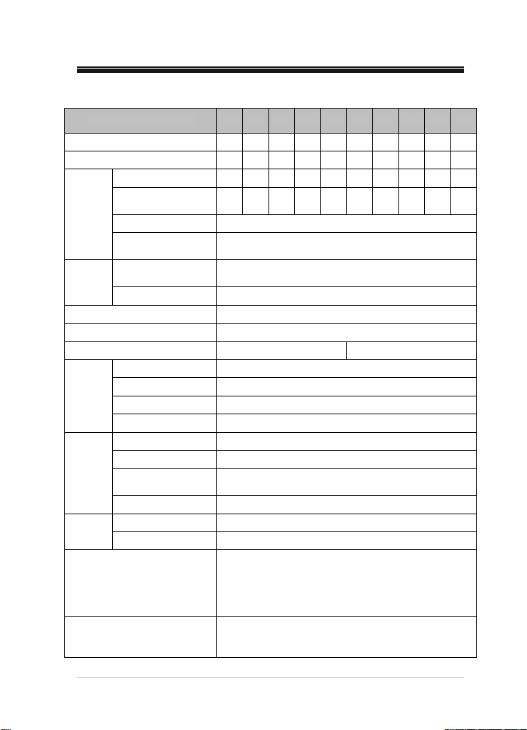
Model NQ-_____S, T( D) 0075 0150 0220 0400 0550 0750 1100 1500 1850 2200
Standard Motor [kW] 0.75 1.5 2.2 4 5.5 7.5 11 15 18.5 22
Standard Motor [HP] 1 2 3 5.5 7.5 10 15 20 25 30
Output Capacity [kVA] 2 2.6 4 5.9 7.9 10.5 15.8
Rated Output Current
Rated
Output
Rated
Input
Protection Class IP55
Switching Frequency [kHz] 1 ~ 15
Control
Operation
Output
Signal
Other Functions
Protection Functions
[A]
Output Voltage [V] 380 ~ 440
Output Frequency
[Hz]
Rated Input Voltage
[V]
Input Frequency [Hz] 50 / 60 (±5%)
Cooling Natural Cooling Forced Fan Cooling
Controlling Method V/F Control, Slip Compensation Control
Frequency Stability 1% of Rated Frequency
Overload Resistance 120%, 1 minute
Torque Boost Manual Torque Boost (0~10%)
Operation Method FND / Term i nal / Communication (CAN) Operation
Frequency Setting FND / Terminal (0~10V or 4~20mA)
Acceleration/
Deceleration Time
Abnormal Reset Automatic Reset upon Automatic Restart Setting
Abnormal Output Output Contact (FLT-AT,CT,BT), LED Output
Operation Status Output Contact (RUN-AT,CT,BT), LED Output
3 4 6 9 12 16 24 30 39 45
0.05 ~ 50 / 60
3φ 380V ~ 440V (-15% ~ +10%)
1 ~ 600 Sec.
Freezing Protection for Pump, Auto Recovery after Power
Fail, High/Low Pressure Alarm, Low Water Level
Detection, Multi-Drive Control, Failure History Storage,
Forced Alternative Operation, PID Control,
Fixed Frequency Operation, Dry running Protection
High Voltage, Low Voltage, Over Current, Surge,
Overload, Inverter Overheating, Output Wire
Disconnection, Communication Error
19.7 25.7 29.6
2-1|
DOOCHPUMP

Display
Code
Use
Condition
[CHAPTER 2 SPECIFICATIONS OF PRODUCT]
Output Frequency, Pump’s Curr ent P re ssur e, Pump’s
Drive Information
Abnormality
Information
Installation
Location
Ambient Temperature
Storage Temperature
Ambient Humidity Under 90% RH (No Due)
Setting Pressure, DC Voltage, Output Current,
Input/Output Pressure (on Differential Pressure Control)
Pressure Sensor Error, High/Low Pressure Alarm, Low
Level Alarm, Drive Error
Altitude 1,000M or lower
Keep out of Corrosive Gases and Liquid, Dust
-10℃ ~40℃
-20℃ ~ 60℃
2-2|
DOOCHPUMP

[CHAPTER 3 EXTERNAL DIMENSION]
3. External Dimension
3-1. NQ-0075T~NQ-0220T
H W D W1 D1 Weight
NQ-0075T 143 151 229 133 217 2.9kg
NQ-0150T 143 151 229 133 217 2.9kg
NQ-0220T 143 151 229 133 217 3kg
3-1|
DOOCHPUMP

3-2. NQ-0400T
[CHAPTER 3 EXTERNAL DIMENSION]
H W D W1 D1 Weight
NQ-0400T 162 151 229 133 217 3.3kg
3-2|
DOOCHPUMP

[CHAPTER 3 EXTERNAL DIMENSION]
3-3. NQ-0550T~NQ-0750T
H W D W1 D1 Weight
NQ-0550T 176 290 290 189 277 5.5kg
NQ-0750T 176 290 290 189 277 5.7kg
3-3|
DOOCHPUMP

[
[CHAPTER 3 EXTERNAL DIMENSION]
3-4. NQ-1100T~NQ-1500T
H W D W1 D1 Weight
NQ-1100T 186 390 290 185 277
NQ-1500T 186 390 290 185 277
3-4| DOOCHPUMP
12.4kg
12.4kg

[
[CHAPTER 3 EXTERNAL DIMENSION]
3-5. NQ-1850T~NQ-2200T
H W D W1 D1 Weight
NQ-1850T 186 440 290 210 277
NQ-2200T 186 440 290 210 277
3-5|
DOOCHPUMP
14kg
14kg

[CHAPTER 3 EXTERNAL DIMENSION]
3-6|
DOO C H P U M P

[CHAPTER 4 INSTALLATION]
4. Installation
4.1 Cautions on Installation
A. Be careful for handling and use.
Since drive consists of sensitive electric/electronic devices, be careful not to damage it
during installation or transportation.
B. Be careful to install the drive on the place with vibration.
In case of installing it on the motor or piping directly, prepare a countermeasure to
reduce vibration.
C. Cautions on Ambient Temperature
Since lifetime and performance of the drive depend on the ambient temperature largely,
maintain the ambient temperature of the place not to exceed allowable temperature
(- 10 ~ 40 ℃). If the ambient temperature is higher than allowable temperature, reduce
output ratings of the drive before use.
D. Install on noninflammable/incombustible materials.
Since the drive becomes high temperature during operation, install it on
noninflammable/incombustible materials.
E. Secure enough space around installation point.
Since the drive is a kind of heating element, be sure to install it toward the direction that
cooling fan flows air from bottom to top and secure enough ambient space not to
interfere the cooling air in order for effective cooling.
F. Install the drive securely in upright position.
Install the drive securely without sway in upright position using fasteners or bolts.
4-1|
DOOCHPUMP

[
[CHAPTER 4 INSTALLATION]
4.2 Wiring Diagram of Terminals
3φ 380V~440
AC Input
50/60 Hz
4-2| DOOCHPUMP

[
[CHAPTER 4 INSTALLATION]
4.3 Wiring of Main Power Supply Circuit
4.3.1 Description on Main Power Supply Terminals
R S T FG FG U V W
Terminal
Sign
R,S,T AC Input To connect commercial AC Input.
FG Ground
U,V,W Drive Output To connect Motor.
4.3.2 Cautions on Main Power Supply Wiring
• Execute wiring work after checking if DC power of drive is discharged (under 30V).
• Be sure to install wiring breaker (MCCB) between AC input power and drive input
power terminals (R,S,T). Use the wiring breaker (MCCB) with 1.5~2 times larger
capacity than rated current of the drive.
• Sometimes EMI occurs due to high speed switching of the drive and it makes radio
interference on electronic devices used around the drive. For that case, install EMC
filters between AC power input and the drive to reduce interference.
• If AC input power is connected to output terminals (U,V,W) of drive, drive will be
damaged. Be sure to connect it to input terminals.
• Even though power input terminals (R,S,T) may be connected regardless to phase
sequence of AC input power, it is required to consider rotation direction of the
motor when connecting input terminals of the motor to output terminals of the
drive (U,V,W). If rotation direction of the motor is reversed, 2 lines from drive output
terminals (U,V,W) should be exchanged each other.
• Do not make short circuit nor ground with drive output terminals (U,V,W). Short
circuit or ground of output terminals may damage on the drive.
• Do not connect static condenser or noise filter at the output of the drive. It may
cause frequent trip on the drive, or static condenser or noise filter may be destroyed
due to overheating.
• Use specified thickness of wires for input/output wiring for the drive. If wires are
Terminal Name Description
It is a ground terminal on drive enclosure. Please ground it.
4-3|
DOOCHPUMP

[CHAPTER 4 INSTALLATION]
thinner than specified thickness, it may cause torque reduced due to voltage
decrease or induce fire accident from overheating.
• Maintain wiring distance between drive and motor within 50m. If it is longer than
50m, be sure to use the motor with reinforced insulation or micro-surge filter.
4.3.3 Cautions on Ground Wiring
• Since a leak current is generated from high speed switching of the drive, it is required to
ground the drive to prevent electric shock.
• Maintain ground resistance within 10Ω during grounding work
• Use thicker wires than specified one for ground wire.
4-4|
DOOCHPUMP

[
[CHAPTER 4 INSTALLATION]
4.3.4 Specifications of Recommended Wires and Terminal Screw
Drive
Capacity
0.75 kW M4 1.2~1.5 2(14) 2(14) 2(14)
1.5 kW M4 1.2~1.5 2(14) 2(14) 2(14)
2.2 kW M4 1.2~1.5 3.5(12) 3.5(12) 2(14)
4 kW M4 1.2~1.5 3.5(12) 3.5(12) 3.5(12)
5.5 kW M5 2.5 5.5(10) 5.5(10) 5.5(10)
7.5 kW M5 2.5 5.5(10) 5.5(10) 5.5(10)
11 kW M6 4~5 8(8) 8(8) 8(8)
15 kW M6 4~5 8(8) 8(8) 8(8)
18.5 kW M6 4~5 14(6) 14(6) 14(6)
22 kW M6 4~5 22(4) 22(4) 14(6)
※ Apply specified torque for fastening the terminal screw.
Size of
Terminal
Screw
Fastening Torque
for Screw (N.m)
Thickness of Wires
mm² (AWG)
R,S,T U,V,W FG
※ Weak fastening may cause malfunction and too strong fastening may destroy terminal
block.
※ Use 600V class wires.
4-5|
DOOCHPUMP

[CHAPTER 4 INSTALLATION]
4.4 Control Circuit Wiring
4.4.1 Arrangement of Control Terminal Block
Power Range : 0.75~4Kw
4-6|
DOOCHPUMP

[CHAPTER 4 INSTALLATION]
Power Range : 5.5~22kW
4-7|
DOOCHPUMP

[CHAPTER 4 INSTALLATION]
4.4.2 Functions of Control Terminal Block
Classification
Pump
Control
Contact
Operation
Input
Signal
Analog
Frequency
Setup
Output
Signal
Signal
Relay
Contact
Com.
RS485
(Option)
CAN
Ter mi nal
Sign
S1P, S1N Pressure Sensor 1 Connection terminal for Pressure Sensor 1
S2P, S2N Pressure Sensor 2
LV1, LV2 Low Level Sensor Connection terminal for low level sensor
P1 Operation Command Operation/Stop Terminal
EST Emergency Stop When EST signal is ON, it turns off drive output.
24V
CG
V1
I1
GND
RUN
(AT,CT,BT)
FAULT
(AT,CT,BT)
CANH,CANL CAN Signal CAN signal line terminal
CG
TX,RX
(AUX1,AUX2)
CG
Terminal Name Description
Contact Operation
Common Terminal
Contact Operation
Common Terminal
Frequency
Setup (Voltage)
Frequency
Setup (Current)
Frequency
Setup
Common Terminal
Abnormal Signal
Output
Multi-function Output
CAN Common
Terminal
RS485 Signal RS485 Signal Terminal
RS485 Common
Terminal
Connection terminal for Pressure Sensor 2
(used for differential pressure control)
Common terminal of input terminal for PNP
contact.
Common terminal of input terminal for NPN
contact.
If entering DC 0~10V, it makes setup frequency.
If entering DC 4~20mA it makes setup
frequency.
Common terminal for Analog frequency setup
terminal
It outputs signal when drive is output. (≤AC250V
5A, ≤ DC30V 5A)
It is output when protection function of system
and drive is activated to cut off output.
(≤AC250V 5A, ≤DC30V 5A)
Common terminal of power ground for CAN
communication
Common terminal of power ground for RS485
communication
4-8|
DOOCHPUMP

[
[CHAPTER 4 INSTALLATION]
4.4.3 Cautions on Control Circuit Wiring
• Maintain wiring distance between pressure sensor and drive within 10m.
• In case of remote control using analog signals, maintain distance between remote
control panel and drive within 50m.
• Set off sensor and analog signal lines enough from power lines.
• Use shield twisted wires for signal lines of control circuit.
• Since GND and CG are insulated each other, do not interconnect or ground them.
4.4.4 Connection of Pressure Sensor and Low Water Level Sensor
• Use the pressure sensor and low water level sensor specified by Dooch.
• General specifications of the pressure sensor and low water level sensor specified by
Dooch are as follows:
• Since terminals on pressure sensor have polarity, be careful about polarity during
installation.
• When using any unspecified pressure sensor and low level sensor, please contact us
before using them.
Category Pressure Sensor Low Water Level Sensor
Excited Voltage DC 12V DC ±15V Pulse
Sensor Output 4~20mA Connection
4-9|
DOOCHPUMP

[
[CHAPTER 4 INSTALLATION]
※
4.4.5 Sink Mode and Source Mode
This product is configured to allow applying both sink mode (NPN: Using CG common
terminal) and source mode (PNP: Using 24V common terminal) to the input terminal logic
of control circuit. It is possible to toggle between sink mode and source mode using
selection switch within the control board.
Wiring methods for sync mode and source mode are shown on figures below.
Sink
Mode(NPN)
Inner power Outer power
Source
Mode(PNP)
4.5.6 Communication Line Wiring
This product basically supports CAN communication that is use for multiple pump control.
When using CAN communication, connect CANH (High of CAN) and CANL (Low of CAN)
on the terminal block and shield wire to CG. Use shield and twisted wire for wiring.
In addition, when using termination resistor for connecting multiple CANs, change the
switch from OPEN to SHORT.
When using RS 485 communication, please contact US.
4-10| DOOCHPUMP

[CHAPTER 5 OPERATION]
5. Operation
5.1. FND
5.1.1 Appearance and Description of FND
FND has five digits of 7-segment, four LED lamps to display various settings and states and
consists of four buttons to operate drive or enter setting.
5.1.2 Functional Description of each Part
1) LED Lamps
LED lamps consist of Run, Stop, Alarm1 and Alarm2 and functions of them are as follows:
- Functions of each Button
• Run and Stop LEDs indicate status of the drive.
• In case of drive error, Alarm2 lamp will be turned on. In case of alarm for pump system,
Run Turned on for waiting and flickered on operation
Stop Turned on during stop
Alarm1
Turned on for High Pressure/Low Pressure/Sensor Error/Low Level
Alarms
Alarm2 Turned on for drive error
Alarm1 lamp will be turned on.
Lamp Part
Button Part
DOOCHPUMP
5-1 |
[CHAPTER 5 OPERATION]
2) FND Part
FND consists of five digits of 7-segment and displays status value of drive and pump and
parameter settings. FND displays are divided into St group (Status Group), Pr group (Pump
Control Group) and dr group (Drive Group).
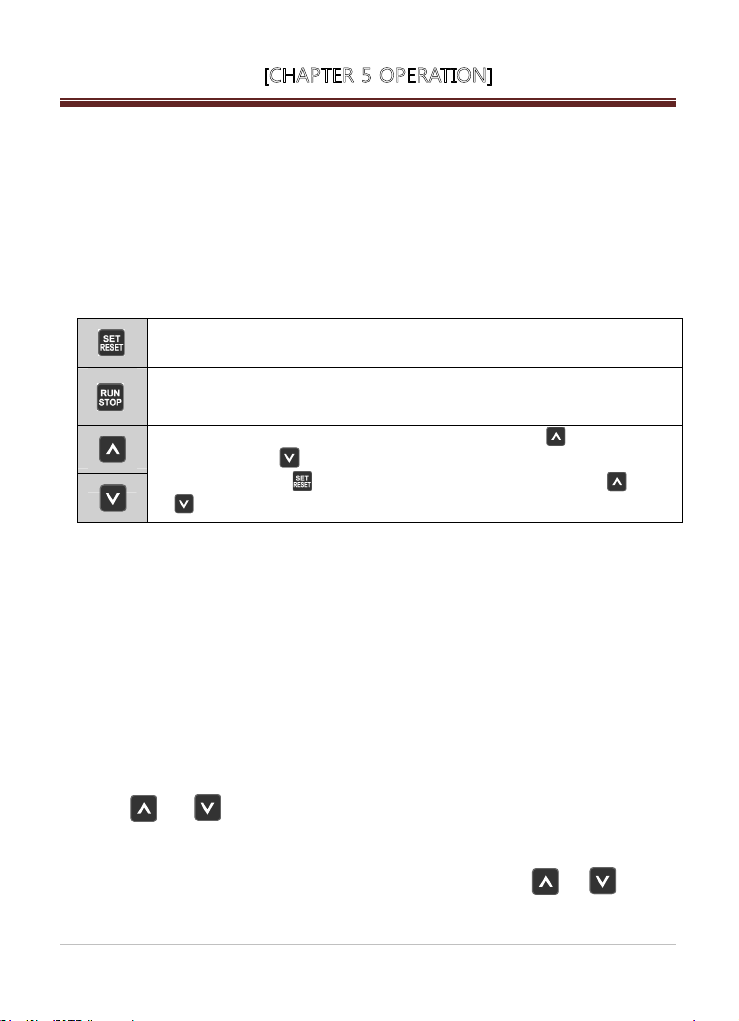
3) Button Part
Button part consists of four buttons and it is used for parameter setting or movement.
• Description on Button’s Functions
It is used for setting up pressure settings, various parameters or Alarm Reset.
It operates or stops the drive.
On operation state, RUN lamp will be turned on.
It is used to change parameter items or parameter settings. Key increases
the value, while key decreases the value. After changing the settings,
be sure to press key for saving the final value. If pressing and
for 3 seconds, parameter group is moved.
5.1.3 How to Change Parameter Settings
• Since any change of parameter settings has direct influence on operation, please be careful
about it.
• Before changing any parameter setting, be sure to write it on paper.
• Do not change the parameter setting except for responsible operator or professional
engineer.
• Since there are items with data or parameter unavailable for change during operation, be sure
to confirm. (Refer to Chapter 6. Table of Functions.)
1) Parameter Group Movement
When applying power first, it enters into St group. In order to move to parameter group,
press and buttons for 3 seconds.
2) Parameter Item Movement
ve between parameter items within parameter group, use and buttons
In order to
to move to desired item.
mo
5-2 |
DOO C H P U M P

[CHAPTER 5 OPERATION]
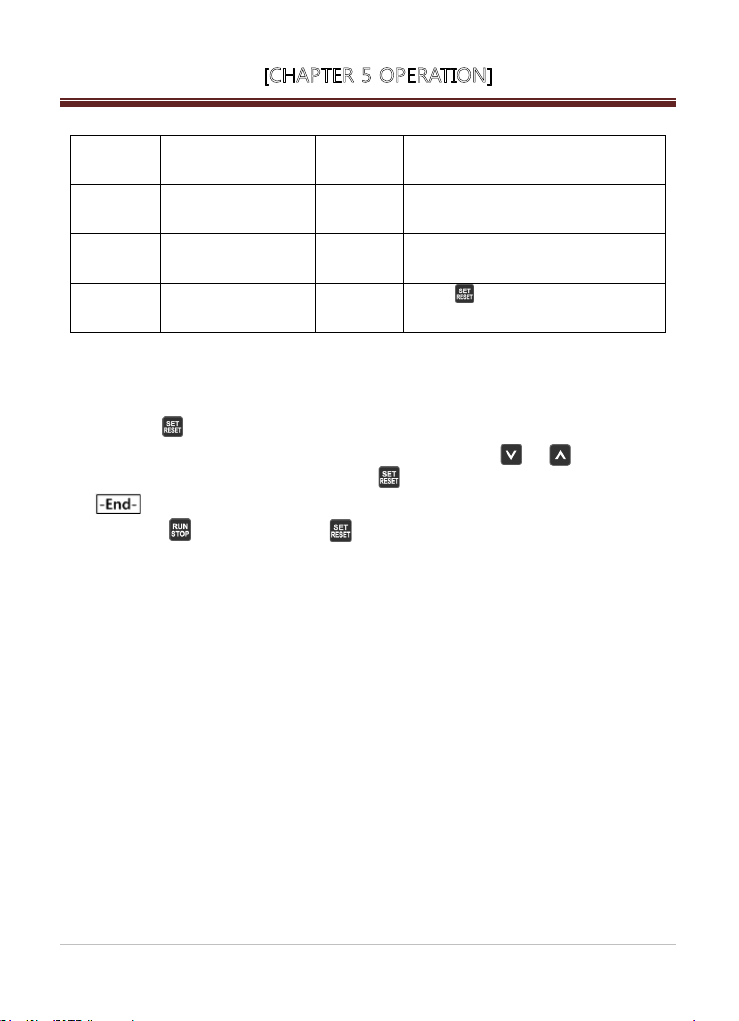
3) How To Change Parameter Settings
In order to change parameter setting, press key at the desired parameter item to enter into
Setting Change Mode. On Setting Change Mode, use and key to change it to desired
setting. Press key again, then message is displayed to apply the setting. If
pressing key on Parameter Edit Mode, setting is not applied and exited from Edit Mode.
5-3 |
DOOCHPUMP

[CHAPTER 5 OPERATION]
5.2 Function Setup
5.2.1 Basic Function Setup
It is a basic parameter setup to operate the drive. Any parameter that is not set by the user,
it is set default value of factory setting.
1) Common Setup
It is a parameter setup to set and confirm commonly when controlling pump using drive
regardless to type of control.
Setup Item
Input Location of Run
Command
Input Method of Target
Frequency
Capacity of Motor dr-10 To set up Capacity of Motor
No. of Poles of Motor dr-11 To set up No. of Poles of Motor
Rated Current of Motor dr-12 To set up Rated Current of Motor
Rated Rotations of Motor dr-13 To set up Rated Rotations of Motor
Rated Voltage of Motor dr-14 To set up Rated Voltage of Motor
No-load Current of Motor dr-15 To set up No-load Current of Motor
Rated Slip Frequency of
Motor
Rated Frequency of
Motor
Efficiency of Motor dr-18 To set up Efficiency of Motor
Rotation Direction
Selection of Motor
Stopping Method of Motor dr-21
Increase/Decrease Time dr-22/dr-23 To set up Increase/Decrease Time of Drive
Parameter
Code
dr-01
dr-02
To select a method to issue Run command
To select a method to control target operation
Description on Function
(FND, Terminal Block)
frequency (Own PID, FND, V1, I1)
dr-16 To set up Rated Slip Frequency of Motor
dr-17 To set up Rated Frequency of Motor
dr-20
To set up Rotation Direction Selection of
Motor Properly
To set up Stopping Method of Motor to stop
the motor
5-4 |
DOOCHPUMP

[CHAPTER 5 OPERATION]
2) Pump Control Function Setup
These parameters are to be set for the pump system when controlling pump using drive.
Setup Item
Pump Capacity Pr-01 To set up Pump Capacity
Pump Control Mode Pr-02 To set up Pump Control Mode
Sensor Capacity and
Correction
To Use Low Water
Level Sensor
3) Drive Control Function upon External Command
These parameters are to be set basically when controlling the drive using external controller.
Setup Item
Frequency Setup upon
V1 Voltage
Frequency Setup upon
I1 Voltage
4) CAN Communication Function Setup
These parameters are to be set basically for CAN communication used on interoperation
or connecting FND/LCD Monitor.
Parameter
Code
Pr-03~06
Pr-76
Parameter
Code
dr-60~63
dr-64~67
Description on Function
To set up capacity of pressure sensor and
correct variation between actual pressure
and pressure sensor
(On constant pressure control, Sensor2 is
not used.)
To decide whether to use low water level
sensor
Description on Function
To set up output frequency range against
voltage when controlling drive using V1
voltage
To set up output frequency range against
current when controlling drive using I1
current
DOOCHPUMP
5-5 |

[CHAPTER 5 OPERATION]
Setup Item
CAN Comm. Mode Pr-50 To set up CAN Comm. Mode
CAN Comm. ID Pr-51
CAN Comm. Speed Pr-52 To set up CAN Comm. Speed
5.2.2 Expansion Function Setup
It is to set up parameters to operate pump system optimally except for those to be set for
operating the drive. Any parameter that is not set by the user, it is set default value of factory
setting.
1) Pump Control Parameters
Setup Item Parameter Code Description on Function
PID Controller Gain
Setup
Control Cycle of PID
Controller
Start Pressure
Variation
Initial Output Ratio on
Starting
Lead Pump
Alternation
Parameter
Code
Pr-07~09
Pr-10
Pr-12
Pr-15
Pr-53~54
Description on Function
To set up CAN Comm. ID
(If ID is ‘0’, CAN Comm. is disabled.)
To set up gain to adjust response
characteristics of PID controller
To set up Control Cycle of PID Controller
Minimum pressure variance to allow drive to
start
To set up initial starting output frequency of PID
controller in order to speed up response against
initial starting
To operate pump alternatively in force during
multi-drive operation
5-6 |
DOOCHPUMP

[CHAPTER 5 OPERATION]
2) Setup Parameters for Pump System Protection
Setup Item
High Pressure Alarm
Low Pressure Alarm
Low Water Level
Alarm
3) Setup Parameter for Fault History Storage
Setup Item
Fault History Storage
and Deletion
Parameter
Code
Pr-70
Pr-72
Pr-71
Pr-73
Pr-74~77
Parameter
Code
Pr-80~86
To set up high pressure alarm level and time
in order to protect discharge pipe from high
pressure
To set up low pressure alarm level and time
in order to protect the pump from damaged
pump
There are two detection methods using low
level sensor or software in order to protect
the pump by detecting existence of water
within suction pipe.
To store or delete fault or alarm generated
from pump system or drive
Description on Function
Description on Function
DOOCHPUMP
5-7 |

[CHAPTER 5 OPERATION]
5.3 Basic Operation
5.3.1 Constant Pressure Control Mode
1) Single Drive Operation
In case of using a single drive to control constant pressure, it is possible to apply it to the
pump system as below.
A. Wiring Diagram
3φ 380V~440V
AC Input
50/60 Hz
• Connect drive wiring so that the power input lines and motor output lines should not be
interchanged.
• Be sure to install wiring breaker at the power input of drive.
5-8 |
DOOCHPUMP

[CHAPTER 5 OPERATION]
• Check the polarity of pressure sensor and connect it properly.
(In case of KELLER 21G series, connect brown line of pressure sensor to SEN1P terminal and
white line to SEN1N terminal respectively.)
• Connect low level sensor (electrode) if necessary.
※ In case of not using low water level sensor (electrode), change setup to use low water level
detection method of software. (To select Para ‘Pr-76’ Low Level Trip Detection Method ‘0’)
B. Setup and Operation Method
• After applying power supply, check if Stop LED on FND is turned on and FND part displays
current press of piping.
※ If is displayed, be sure t
(Connection status or defective pressure sensor, etc.)
※ Caution: Do not surprise even if drive is automatically operate after 10 seconds from
power supply.
This is a normal phenomenon that power fail recovery function operates.
(Refer to power fail recovery function.)
C. Operation Parameters
- Basic Setup Parameters
Setup
Sequence
1
2
3
4
5
Setup Item
Run Command Input
Location Setup
Target Frequency Input
Method Setup
Pump Control Mode
Setup
Sensor1 Capacity
Setup
Sensor1 Pressure
Variation Correction
o check wiring of pressure sensor.
Parameter
Code
Functional Description
dr-01 To set up Run command with FND.
dr-02
Pr-02
Pr-03
To set up Target Frequency Input
Method of drive with own PID.
To set up Pump Control Mode to
Constant Pressure Mode.
To set up rated capacity of pressure
sensor used.
To correct variation between value of
Pr-04
used pressure sensor and real pressure
value.
5-9 |
DOOCHPUMP
[CHAPTER 5 OPERATION]
6 Comm. ID Setup Pr-51
7 Target Pressure Setup St Group
8
Motor Rotation
Direction Selection
dr-20
9 Operation
D. Target Pressure Setup
• If you don’t know about correct pressure setting, contact the specialist.
• If you press key for more than 3 seconds on a mode displaying S of St group, it
changes to pressure setting screen. At the moment, if you use key or key to
change the value to desired setting and press key, the pressure setting is changed with
screen.
※ If you press key without pressing key after changing the setting, the setting will
not be changed and the screen will exit from pressure setting change mode.)
※ If the pressure setting is changed, the high pressure alarm (‘Pr-70’) setting
automatically set to the value 2 bar higher than the pressure setting.
E. Checkup on Rotation Direction of Pump
• It would be correct if the rotation direction is counter clockwise from a viewpoint of fan
cover of the pump. (If the rotation direction is reversed, it cannot generate the normal
pressure.)
• In order change the rotation direction...(Select one of the methods below.)
- Change two from three wires of the motor input.
- Change the value of Parameter ‘dr-20’ to other one. ‘dr-20’.
To set up CAN Comm. ID to ‘0’ in order
to make CAN Comm. Disabled.
To set up target pressure of pump
system.
To make rotation direction of motor
same as pump operation direction
Press
key, them pump operates
with target pressure.
will be
5-10 |
DOO C H P U M P

[
[CHAPTER 5 OPERATION]
2) Multi-Drive Operation of Drives
In case of using several drives linked together to control constant pressure, it is possible to
apply it to the pump system as follows:
A. Wiring Diagram
3φ 380V~440V
AC Input
50/60 Hz
3φ 380V~440V
AC Input
50/60 Hz
3φ 380V~440V
AC Input
50/60 Hz
• Connect drive wiring so that the power input lines and motor output lines should not be
interchanged.
• Be sure to install wiring breaker at the power input of drive.
• Check the polarity of pressure sensor and connect it properly. Connect auxiliary pressure
sensor to each drive depending on the system.
• In order to detect low level of suction pipe connect low level sensor (electrode) if necessary.
In case of not using low level sensor (electrode), change setup to use low level detection ※
method of software
(To select Parameter ‘Pr-76’ Low Level Trip Detection Method ‘0’)
5-11 |
DOOCHPUMP

[CHAPTER 5 OPERATION]
B. Setup and Operation Method
• After applying power supply, check if Stop LED on FND is turned on and FND part displays
P - 0.0
current press
Er - 01
If※ is displayed, be sure to check wiring of pressure sensor.
(Connection status or defective pressure sensor)
Caution: Do not surprise even if drive is automatically operate after 10 seconds from power ※
supply. This is a normal phenomenon that power fail recovery function operates.
(Refer to power fail recovery function.)
C. Operation Parameters
- Basic Setup Parameters
Setup
Sequence
1
2
3
4
5
6
7
8
9
Run Command
Input Location Setup
Target Frequency
Input Method Setup
Sensor1 Capacity
Sensor1 Pressure
Variation Correction
Comm. ID Setup Pr-51
Target Pressure
Direction Selection
Operation
of piping.
Setup Item
Pump Control
Mode Setup
Setup
Setup
Motor Rotation
Parameter
Code
dr-01 To set up Run command with FND.
dr-02
Pr-02
Pr-03
Pr-04
St Group To set up target pressure of pump system.
dr-20
To set up Target Frequency Input Method of
drive with own PID.
To set up Pump Control Mode to Constant
Pressure Mode.
To set up rated capacity of pressure sensor
used.
To correct variation between value of used
pressure sensor and real pressure value.
To set up CAN Comm. ID to 1~6 so that it
should not be duplicated with other drive.
To make rotation direction of motor same as
pump operation direction
Press key, the pump operates with
target pressure.
Functional Description
5-12 |
DOO C H P U M P

[CHAPTER 5 OPERATION]
D. Target Pressure Setup
• If you don’t know about correct pressure setting, contact the specialist.
• In case of linked drive operation, when setting up pressure on one drive, setup pressures are
automatically changed for all drives through CAN communication.
• If you press
to pressure setting screen. At the moment, if you use
to desired setting and press
key for more than 3 seconds on a mode displaying S of ST group, it changes
key or key to change the value
key, the pressure setting is changed with screen.
(If you press
key without pressing key after changing the setting, the setting will not
be changed and the screen will exit from pressure setting change mode.)
If the pressure setting is changed, the high pres※ sure alarm ( ‘Pr-70’) setting will be automatically
set to the value 2 bar higher than the pressure setting.
E. Checkup on Rotation Direction of Pump
• It would be correct if the rotation direction is counter clockwise from a viewpoint of fan cover of
the pump. (If the rotation direction is reversed, it cannot generate the normal pressure.)
• In order change the rotation direction...(Select one of the methods below.)
- Change two from three wires of the motor input.
Change the value of Parameter ‘dr-20’ to other one.
-
5-13 |
DOOCHPUMP
[CHAPTER 5 OPERATION]
5-14 |
DOO C H P U M P
[CHAPTER 6 FUNCTION TABLE & DESCRIPTION]
6. Function Table of Q Drive
6.1 Status Group
DISPLAY Name Explanation Remark
P
S
Present
pressure
Setting
pressure
H Output Hz
It shows measured present
pressure
It shows setting pressure and
operator can input pressure
value.
It shows present drive output to
HZ
o Output ratio It shows present drive output to%
U Voltage It shows voltage of DC Link
A Current I shows present output current Unit [A]
O
I
Discharge
pressure
Suction
pressure
In case of difference pressure
control, It shows discharge
pressure
In case of difference pressure
control, It shows suction
pressure
In case of difference
pressure,
It shows difference pressure.
If you press setting button
for longer than 2 seconds,
It change to pressure input
mode.
Input voltage *√2=DC Link
voltage[V]
Differential pressure
Differential pressure
6-1 |
DOOCHPUMP

[CHAPTER 6 FUNCTION TABLE & DESCRIPTION]
6.2 Pump Control Group
DISPLAY Name Range
Pr-00 Jump Code 1~92
Pr-01 Pump Capacity Setup 0.75~25.00[kW] - X O X
Pr-02 Pump Control Mode 0~1 1 O O X
Capacity Setup of
Pr-03
Sensor1
Correction Value of
Pr-04
Sensor1
Capacity Setup of
Pr-05
Sensor2
Correction Value of
Pr-06
Sensor2
P Gain of PID
Pr-07
Controller
Pr-08
Pr-09
Pr-10
Pr-11
Pr-12
Pr-13
Pr-14
Pr-15
Pr-40 485 Comm. Mode
Pr-41 485 Comm. ID
Pr-42 485 Comm. Speed
Pr-43 Comm. Delay time
Pr-50
Pr-51 CAN Comm. ID 0~6 0 X Ο X
I Gain of PID
Controller
D Gain of PID
Controller
Control Cycle of PID
Controller
Selection of Freezing
Prevention
Starting pressure
Variation
Stopping Time after
reaching Setup
Pressure
Ratio of Min Output
Freq. of Stop Mode
after reaching Setup
Pressure
Ratio of Initial Output
on Starting
CAM Comm.
Mode
1.0~25.0[bar] 16.0 X Ο X
-1.0~1.0[bar] 0.0 X Ο O
1.0~25.0[bar] 16.0 Χ Ο X
-1.0~1.0[bar] 0.0 Χ Ο O
0~100[%] 10 Ο Ο O
0~100[sec] 1 Ο Ο O
0~100[ms] 0 Ο Ο O
10~200[ms] 200 Ο Ο X
0~1 0 Ο Ο O
0~2.0[bar] 0.3 Ο Χ O
5~200[sec] 30 Ο Χ O
0~100[%] 100 Ο Χ O
5~100[%] 50
0~1
1~250
1~5
1~9999[ms]
0~1 1 X Ο
Factory
Setting
Para.
Link
51 X O O
X X
0
1
4
5
Diff.
Pressure
Use
ΟΟ Ο X
ΟΟ X
ΟΟ X
ΟΟ X
Change
on
Operation
X
Ref.
Page
6-6
6-7
6-8
6-9
6-10
6-11
6-2 |
DOOCHPUMP

[CHAPTER 6 FUNCTION TABLE & DESCRIPTION]
Name Range
Factory
Setting
Para.
Link
Pr-52 CAN Comm. Speed 1~5 1 X O X
Pr-53 Alteration type 0~1 0
Lead pump
Pr-54
alternation time
Standby Pump wating
Pr-55
time
PID control Type
Pr-61
Setup
0~24(hour) 12 O O O
0~100[sec] 5 Ο Ο O
0~1 0 O O X
Output Ratio of
Pr-64
Starting AllPID
70~100[%] 100 O O O
Increase
High Pressure Alarm
Pr-70
Level
Low Pressure Alarm
Pr-71
Level
High Pressure Alarm
Pr-72
Time
Low Pressure Alarm
Pr-73
Time
Low Level Trip Time
Pr-74
of Pressure Sensor
Low Level Trip
Pr-75
Pressure Level
Low Level Detection
Pr-76
Method Selection
Low Level Trip Time
Pr-77
of Low Level Sensor
0~Sen1 Capacity
[bar]
16.0 Ο Χ O
0~10.0[bar] 0.5 Ο Χ O
0~100[sec] 5 Ο Χ O
0~200[sec] 20 Ο Χ O
0~250[sec] 20 Ο Χ O
0~1.0[bar] 0.3 Ο Χ O
0~1 0 X Χ X
0~250[sec] 2 Ο Χ O
Pr-80 Fault History - - X O X
Pr-81 Fault History 1 - - X O X
Pr-82 Fault History 2 - - X O X
Pr-83 Fault History 3 - - X O X
Pr-84 Fault History 4 - - X O X
Pr-85 Fault History 5 - - X -O X
Pr-86 Delete Fault History 0~1 0 X O O
Pr-87 Sensor percentage 0~200 100 X X O
Pr-90 Initialization Code 0~1 0 X O X
Pr-92 S/W Version - - X O X
Diff.
Pressure
Use
Change
on
Operation
6-3 |
DOOCHPUMP
Ref.
Page
6-11
6-12
6-13
6-14
6-15

[CHAPTER 6 FUNCTION TABLE & DESCRIPTION]
6.3 Drive Control Group
★To setup initial value according to drive capacity
☆To setup initial value with basis of Dooch induction motor
Change
DISPLAY Name Range Factory Setting
CAN Comm. Speed 1~90 1
dr-00
Command Input Location
dr-01
Setup
Target Freq. Input
dr-02
Method Setup
dr-03 Target Freq. Value Setup
dr-10 Motor Capacity Selection 0.10~75.00[kW]
No. of Motor Poles
dr-11
Selection
dr-12 Rated Current of Motor 1.0~100.0[Arms]
dr-13 Rated Rotations of Motor 1~9999[rpm]
dr-14 Rated Voltage of Motor 200.0~500.0[Vrms]
Non-load Current of Motor
dr-15
Rated Slip Frequency of
dr-16
Motor
Rated Frequency of
dr-17
Motor
dr-18 Efficiency of Motor 50~100[%]
Rotation Direction
dr-20
Selection of Motor
Stopping Method of
dr-21
Motor
dr-22 Increase Time 1.0~600.0 3.0 O
dr-23 Decrease Time 1.0~600.0 6.0 O
Motor Overload Trip
dr-30
Selection
Motor Overload Trip
dr-31
Level
Motor Overload Trip
dr-32
Time
dr-33 Stoll Prevention Setup 0~1 0 X
dr-34 Stoll Prevention Level 100~200[%] 150 X
Motor Overheat
dr-35
Selection
dr-36 Ground Detection 0~1 0 O
dr-37 No. of Restart after Trip 0~50 3 O
0~1 0 X
0~3 0 X
Min Freq. (dr-42)~Max
Freq.
1~2 1 X
0.5~100.0[Arms]
0.10~10.00[Hz]
0~1 1 X
0~1 0 X
0~1 0 X
0~1 0 O
100~200[%] 120 O
5~200[sec] 60 O
0~1 0 O
30.0 O
★
☆
☆
☆
☆
☆
☆
on
Operation
O
X
X
X
X
X
X
X
Ref.
Page
6-15
6-16
6-17
6-18
6-19
6-20
6-4 |
DOOCHPUMP

[CHAPTER 6 FUNCTION TABLE & DESCRIPTION]
DISPLAY Name Range Factory Setting
Waiting Time of Automatic
dr-38
Restart after Trip
dr-40 Drive Control Mode 0~1 0 X
dr-41 Torque Boost Amount 0~10.0[%] 2.0 X
dr-42 Start Frequency. 0.10~40.00[Hz] 0.50 X
dr-43 Max Operation Freq.
dr-44 Switching Frequency. 1.0~15.0[kHz] 5.0 O
dr-50 Fan Operation Type 0~2 1 O
Power Consumption
dr-51
Correction
dr-52 Output Power Indication 0.0~100.0[kW] -
Indicating Accumulated
dr-53
Mega Wh
Indicating Accumulated
dr-54
Killo Wh
Temp. of Power
dr-55
Semiconductor
dr-56 Ambient Temp. Display
dr-57 Output Power Display 0.0~500.0[V] -
dr-60 V1 Min Input Voltage 0.0~5.0[V] 0.0 O
Corresponding Freq.
dr-61
toV1 Min Input Voltage
dr-62 V1 Max Input Voltage 5.1~10.0[V] 10.0 O
Corresponding Freq. to
dr-63
V1 Max Input Voltage
dr-64 I1 Min Input Current 0~10[mA] 4 O
Corresponding Freq. to I1
dr-65
Min Input Current
dr-66 I1 Max Input Current 11~20[mA] 20 O
Corresponding Freq. to I1
dr-67
Max Input Current
dr-70
dr-71 Month/Date Display 01.01~12.31 dr-72 Hour/Minute Display 00.00~23.59
dr-89 Initializing Integrated Watt 0~1
dr-90 Initialization Code 0~1 0 X
1~250[sec] 10 O
40.0~Rated Freq. of
Motor [Hz]
0.0~1000.0 100.0 O
0~9999[MWh] -
0~9999[kWh] -
0~200℃
0~200℃
0.00~30.00[Hz] 0.00 O
30.01~ Rated Freq. of
Motor [Hz]
0.00~30.00[Hz] 0.00 O
30.01~ Rated Freq. of
Motor [Hz]
60.00 X
-
-
Rated Freq. of
Motor
Rated Freq. of
Motor
0 X
Change
Operation
- 0~9999 Year Display
on
O
O
Ref.
Page
6-20
6-21
6-22
-
6-23
6-5 |
DOOCHPUMP

[CHAPTER 6 FUNCTION TABLE & DESCRIPTION]
6-4. Description on Functions of Parameter Settings
6-4-1 Pump Control Group
Pr-00 Jump Code
ㆍ It allows moving to desired code number directly.
ㆍ It is also possible to move to other code using key after moving.
Pr-01 Pump Capacity
ㆍTo set up and confirm pump capacity.
ㆍInitial value is automatically set by drive capacity.
Related Functions
dr-10 Capacity of Motor
dr-11 No. of Poles of Motor
dr-12 Rated Current of Motor
dr-13 Rated Rotations of Motor
dr-14 Rated Voltage of Motor
dr-15 No-load Current of Motor
dr-16 Rated Slip Frequency of Motor
dr-17 Rated Frequency of Motor
dr-18 Efficiency of Motor
Pr-02 Pump Control Mode
ㆍ To set up pump control method.
Setup Data Functional Description Related Functions
Pr-03,
Pr-04
Pr-05
Pr-06
Pr-03 Capacity of Sensor 1
Pr-04 Correction of Sensor 1
6-6 |
0
1
DOOCHPUMP
Differential Pressure
Control Method
Constant Pressure
Control Method (Factory
Setting)
Capacity of
Sensor 1
Correction of
Sensor 1
Capacity of
Sensor 2
Correction of
Sensor 2
Discharge
Direction
Suction
Direction

[CHAPTER 6 FUNCTION TABLE & DESCRIPTION]
Pr-03 Sensor 1 Capacity Setup
ㆍ Enter the maximum value that the pressure sensor can measure.
ㆍ By entering capacity of pressure sensor attached to the drive being used, it is possible to display
the currently measured pressure.
Example) In case the using sensor has 10bar, enter 10.0.
If the using sensor has 16bar, enter 16.0.
ㆍ and enter the rated value of the pressure sensor for normal pump operation.
Factory Setting Input Range
]rab[ 0.52 ~ 0.0 ]rab[ 0.61
Pr-04 Sensor 1 Correction Setup
ㆍ It corrects pressure variation between analog or digital pressure meter and the one displayed on
drive FIND.
Factory Setting Input Range
]rab[ 0.1 ~ 0.1- ]rab[ 0.0
Pr-05 Sensor 2 Capacity Setup
ㆍ It is used in case of pressure difference control mode.
ㆍ Setup method is same as described on Pr-03.
Pr-06 Sensor 2 Correction Setup
ㆍ It is used in case of pressure difference control mode.
ㆍ Setup method is same as described on Pr-04.
Pr-07 P Gain of PID Controller
ㆍ It is relevant to ‘P’ (Proportional Constant) out of PID control parameters.
ㆍ If Reference and Feedback is in pressure unit [bar], PID P-Gain 100% means that if PID I-Gain is
0 and 100bar error is maintained, controller output is 1.0[Hz].
Factory Setting Input Range
]%[ 001 ~ 0 ]%[01
6-7 |
DOOCHPUMP

[CHAPTER 6 FUNCTION TABLE & DESCRIPTION]
Pr-08 I Gain of PID Controller
ㆍ It is relevant to ‘I’ (Integral Constant) out of PID control parameters.
ㆍ PID I-Gain 1 second means the time required for the output power to be accumulated to 1.0[Hz]
when 100 bar error is maintained.
Factory Setting Input Range
1[sec]
Pr-09 D Gain of PID Controller
ㆍ It is relevant to ‘D’ (Differential Constant) out of PID control parameters.
ㆍ PID D-Gain means that change rate of error for a specified time will be out on PID control cycle
time.
Factory Setting Input Range
0[ms]
Pr-10 PID Control Cycle
ㆍ It sets up PID control cycle.
ㆍ It outputs values calculated with PID in PID control cycle time unit.
Factory Setting Input Range
0[ms]
Pr-11 Freezing Prevention Function
ㆍ It sets up freezing prevention mode of pump.
ㆍ It is to prevents pump from being broken due to low temperature (below zero) in winter using
ambient temperature sensor information within the drive. The function is operated with a
frequency not generating pressure between 0~10 seconds and maintained as stopped status
between 11~59 seconds based on 1 minute. This function is to prevent the pump from
freeze and burst by generating frictional heat upon rotation within pump casing.
This function is not for preventing freeze and burst of pipe.
0 ~ 100[sec]
0 ~ 100[ms]
0 ~ 200[ms]
6-8 |
Setup Data Functional Description
0(Factory Setting)
1
DOOCHPUMP
OFF
ON

[CHAPTER 6 FUNCTION TABLE & DESCRIPTION]
Pr-12 Start Variation
ㆍ It sets up start variation pressure value. That is, the operation starts when the current pressure
has larger variance than the specified value comparing to setting.
ㆍ In case of alarm occurrence, operation does not start.
Factory Setting Input Range
Pr-13 Stopping Time after Reaching Setup Pressure
ㆍ When the pump pressure reaches to setting and maintained for longer than setup time, it starts to
reduce speed. If there is pressure difference as much as starting variation, the pump starts to
operate again during decrease of speed and if not, it stops.
ㆍ Input Range : 5 ~ 200 [sec]
Factory Setting Input Range
Pr-14 Min Output Frequency Ratio to Stop after Reaching Setup Pressure
ㆍ In order to stop after reaching to specified pressure, the drive is able to stop only if the current
minimum output frequency ratio is less or equal to setup ratio.
Pr-15 Initial Output Ration on Starting
ㆍ It refers to the minimum output ratio on starting of the drive. That is, if it is set to 50% when the
maximum operation frequency is 60 Hz, it can start from 30 Hz.
Factory Setting Input Range
Pr-40 485 Comm. Mode
ㆍ To set up 485.
Setupdata Functional Description
0.0 ~ 2.0[bar]0.3[bar]
5 ~ 200[sec]30[sec]
Input RangeFactory Setting
0 ~ 100[%]100[%]
5 ~ 100[%]50[%]
Not use 485 comm.0(factory setting)
Use 485 comm. 1
6-9 |
DOOCHPUMP
[CHAPTER 6 FUNCTION TABLE & DESCRIPTION]
Pr-41 485 comm.
ㆍIt setsup 485 comm. ID set up
Pr-42 485 comm. speed
ㆍ 485 comm. speed set up
Pr-43 485 comm. delay time
ㆍ485 comm. delay time set up
Pr-50 CAN Communication Mode
ㆍ It set up for multi-drive control, when each drive has different version
* Available for version 1.3x. Please refer version check page
*
When set up for 0(NQ Ver 1.2x), the Pr-53 alteration automatically changed to 0(in order of ID)
Setup Data Functional Description
1~250(Factory Setting)
Setup Data Functional Description
Setup Data Functional Description
1~9999(msec)
Setup Data Functional Description
If the number of data request protocol is
different, data is not transmitted.
1200kbps1
2400kbps2
4800kbps3
9600kbps4(Factory Setting)
19200kbps5
When receive data request protocol, data transmit
after set up delay time(Factory set up : 5[msec]
NQ Ver 1.2x0(Factory Setting)
NQ Ver 1.3x 1
Pr-51 Communication ID Setup
ㆍ It is CAN Communication ID on Multi-Drive control mode.
ㆍ Be sure to not duplicate ID for setup.
6-10 |
DOOCHPUMP

[CHAPTER 6 FUNCTION TABLE & DESCRIPTION]
Setup Data Functional Description
Single Mode0(Factory Setting)
Related Functions
Multi-Drive
1~6
control
Comm. ID
No.
Pr-52 CAN Communication Speed
ㆍ It sets up CAN communication speed. In case of long connection distance, it is better to reduce
the communication speed.
Setup Data Functional Description
Pr-53 Alternation method
ㆍIt determines the order of Q-Driver’s run, stop, alternation on Multi-Drive operation mode.
Setup Data Functional Description
0 In order of low watt-hour
* Setting is available for Ver 1.3x
* When Pr-50 can comm. mode is 0, alternation is set 0.
dr-02 Target Frequency Input Method
Pr-52 CAN Communication Speed
Pr-53 Lead Pump Alternation method
Pr-54 Lead Pump Alternation Time
Pr-55 Stand-by Pump Waiting Time
Pr-61 PID Type on Multi-Drive control
40kbps1(Factory Setting)
50kbps 2
100kbps 3
200kbps 4
250kbps 5
In order if ID1(Factory Setting)
Pr-54 Lead Pump Alternation Time
ㆍ Alternative operation refers to an operation that when it reaches time specified by the user, the
drive with a lot of power consumed is to be stopped and the one with less power consumption is
to be started alternatively at the same time in order to prevent a specific drive(pump) being
operated constantly. If times is set, drives are forcedly shifted.
Setup Data Functional Description
Release of alternation 0
1~24(hour) Alternation time setup. (Factory Setting 12[hour])
6-11 |
DOOCHPUMP

[CHAPTER 6 FUNCTION TABLE & DESCRIPTION]
Pr-55 Stand-by Pump Waiting Time on Multi-Drive Control Mode
ㆍ This is to give some delay to stand-by pump. If the stand-by pump starts operation before
the main drive outputs maximum frequency then the pressure may increase suddenly.
Factory Setting Input Range
0 ~ 100[sec]5[sec]
Pr-61 PID Type Setup on Multi-Drive Control Mode
ㆍ This is to improve energy efficiency on multiple pump operation and selectable for the user.
Master control means acceleration/deceleration operation upon PID by Master for only one drive.
Centralized control is a method that all of drivers participating into operation are allocated with
target value for the output frequency by one PID controller of Master.
This function has an advantage to prevent overload on the drive.
Setup Data Functional Description
Master Control0 (Factory Setting)
1
Centralized
Control
Pr-64
Pr-64 Output Ratio on Starting Increase of AllPID(Preparing)
ㆍ It is an output ratio to start the next drive by applying it centralized control method for multiple
pump operation. That is, if the output ratio of drive in operation is higher than a specified value,
the next drive to be linked starts to be operated.
Factory Setting Input Range
Pr-70 High Pressure Alarm Level
ㆍ It sets standard pressure value to issue the high pressure alarm.
※ When setting the setup pressure, it is automatically set to setup pressure + 2bar.
Factory Setting Input Range Related Function
20.0[bar] 0.0~20.0[bar] Pr-72 High Pressure Trip Time
Pr-71 Low Pressure Alarm Level
ㆍ It sets standard pressure value to issue the low pressure alarm.
Factory Setting Input Range Related Function
0.5[bar] 0.0~10.0[bar] Pr-73 Low Pressure Trip Time
Related Function
Output Ratio on Starting
Increase of All PID
70 ~ 100[%]100[%]
6-12 |
DOOCHPUMP

[CHAPTER 6 FUNCTION TABLE & DESCRIPTION]
Pr-72 High Pressure Alarm Time
ㆍ It sets maintaining time of high pressure alarm level to issue the high pressure alarm. That is, if
the current pressure increases above the high pressure alarm level (Pr-70) and maintains its
state for a specified time, a high pressure alarm is displayed and operation stops.
Factory Setting Input Range Related Function
5[sec] 0~100[sec] Pr-70
Pr-73 Low Pressure Alarm Time
ㆍ It sets maintaining time of low pressure alarm level to issue the low pressure alarm. That is, if the
current pressure decreases under the low pressure alarm level (Pr-71) and maintains its state for
a specified time, a low pressure alarm is displayed and operation stops.
Factory Setting Input Range Related Function
20[sec] 0~200[sec] Pr-71 Low Pressure Alarm Level
Pr-74 Low Water Level Alarm Time of Pressure Sensor
ㆍ It sets maintaining time of alarm level to issue the low water level alarm.
That is, if the current pressure decreases under the low pressure alarm level (Pr-75) and
maintains its state for a specified time, an alarm is displayed and operation stops.
ㆍ It is applied when low water level sensor setup (Pr-76) is released.
Factory Setting I nput Range Related Function
Pr-75 Low Pressure Alarm Level
30[sec] 0~250[sec]
Pr-76
High Pressure Alarm
Level
Low Pressure Alarm
Method Selection
Pr-75 Low Water Level Alarm Pressure Level
ㆍ It is a pressure level to determine low water level when selecting software detection method from
Low Water Level Alarm Detection Method Selection (Pr-76).
Factory Setting Input Range Related Function
Pr-74
0.3[bar] 0.0~1.0[bar]
Pr-76
Low Water Level Alarm
Time of Pressure Sensor
Low Water Level Alarm
Method Selection
6-13 |
DOOCHPUMP

[CHAPTER 6 FUNCTION TABLE & DESCRIPTION]
Pr-76 Low Water Level Alarm Method Selection
ㆍ It is a mode to set up low water level alarm detection method.
ㆍ In case of setting up low water level sensor, it is required to attach electrode outside to determine
existence of water within piping.
ㆍ In case of multi-drive operation, low water level sensor should be linked to the lowest ID Drive.
※ If there is no water on suction part, all of drives (pumps) will stop.
When it is set to Software detection, it detects the alarm on the basis of low water level alarm
pressure level (Pr-75) and low water level alarm time (Pr-74). That is, if the operation is
continued for more than low water level
level alarm pressure level (Pr-75), it is required to display alarm and stop operation as it is
determined that there is no water within the piping.
Setup Data Functional Description Related Function
0
(Factory
Setting)
1 Low water level sensor setup Pr-77
Software detection using
pressure sensor
Pr-77 Low level Sensor Low Level Trip Time
ㆍ It sets maintain time of low level sensor signal to issue low level alarm.
That is, if the low level sensor signal is continued for more than trip time when low level sensor is
selected from low level trip method (Pr-76), it is required to display alarm and stop operation as it
is determined that there is no water within the suction piping.
Setup Data Functional Description
0 Release of low level detection using low level sensor
Pr-80 ~Pr-85 Fault History List
ㆍ Pr-80 displays Error Code value occurred currently.
ㆍ Pr-81 ~ Pr-85 are memorized in reverse order of Error occurrence.
ㆍ It is possible to enter into using
and error content of the fault using key.
FND Display Description
tSF, tOP, tUP, tUL, tASH etc Error Content (Refer to Chapter 8 Fault History Table)
Stdy, StOP, AdOFS, wdOG Operation status with Error
key and to confirm frequency, curren t, operation state
e (Pr-74) with pressure under the low water
alarm tim
Pr-74
Pr-75
Time Setup (Factory Setting 2[sec])1 ~ 250[sec]
Frequency with Error H xx.x
Current with Error A xx.x
No. of Errors coourred t xx
Low Water Level Alarm Time
Of Pressure Sensor
Pressure Level for
Low Water Level Alarm
Low Level Alarm Time of
Low Water Level Sensor
6-14 |
DOOCHPUMP

[CHAPTER 6 FUNCTION TABLE & DESCRIPTION]
Pr-86 Deletion of Fault History
ㆍ It deletes all of the fault history
Setup Data Functional Description
To maintain error contents(Factory Setting) 0
To delete all of error contents 1
Pr-87 Sensor percentage
ㆍIt corrects sensor by % unit.
ㆍIn order to decrease sensor value, enter smaller value than 100 based on 100% while in order to
increase it, enter larger value than 100.
Pr-90 Initialization Code
ㆍ It carries out initialization with factory settings.
Setup Data Functional Description
0 (Factory Setting) To maintain settings (Factory Setting)
Pr-92 S/W Version
ㆍ It displays program version.
6-4-2 Drive Control Group
dr-00 Jump Code
ㆍ It allows moving to desired code number directly.
ㆍ It is also possible to move to other code using key after moving.
dr-01 Command Input Location Setup
ㆍ It sets operation command location.
When selecting FND key, it is possible to issue operation command using key on main body of
drive. When setting up terminal block, it is possible to issue operation command using external
input(P1)
Setup Data Functional Description
0 (Factory Setting) Operation Command with FND
To initialize with factory settings 1
Operation Command with Terminal Block(P1) 1
6-15 |
DOOCHPUMP

[CHAPTER 6 FUNCTION TABLE & DESCRIPTION]
dr-02 Target Frequency Input Method Setup
ㆍIt sets up target frequency input method of drive.
Setup Data Functional Description
0 (Factory Setting) Setup with own PID operation
1
dr-03 Target Frequency Value Setup
ㆍWhen using as a fixed frequency, it is possible to set up target frequency value.
Target Frequency Input Method (dr-02) should be set with FND.
Factory Setting Input Range
30.0[Hz] Start Freq. (dr-42) ~Max Freq (dr-43)[Hz]
dr-10 Motor Capacity
ㆍ It sets motor capacity.
ㆍ It is set when pump drive is released from the factory. Setting value is for displaying.
It is used when the current pump drive checks the motor capacity being set.
Changing the setting does not have influence other parameters.
Factory Setting Input Range
Initial value is set upon drive capacity 0.10~ 75.00 [kW]
Setup when using fixed freq.
on the main body of FND
drive
Setup with external voltage V1(0~10V)2
Setup with external current I1(4~20mA)3
Related Function
dr-03
Target Freq. Value
Setup
dr-11 Motor Pole Selection
ㆍ It sets No. of motor poles.
ㆍ It is set when pump drive is released from the factory.
Setup Data Functional Description
2 Pole Motor 1
4 Pole Motor 2
dr-12 Motor Rated Current
ㆍ It sets up rated current (RMS) of the motor. It is based on the rated current indicated on the
nameplate of the motor.
ㆍ It is applied to Stall Prevention Level, Slip Compensation Control and Overload Trip Level
Factory Setting Input Range
Initial value is set upon drive capacity 1.00 ~ 100.0 [Arms]
6-16 |
DOOCHPUMP

[CHAPTER 6 FUNCTION TABLE & DESCRIPTION]
dr-13 No. of Rated Rotations of Motor
ㆍ It sets No. of rated rotations of motor. It is based on data indicated on the nameplate of the motor.
Factory Setting Input Range
Initial value is set upon drive capacity 1 ~ 9999 [rpm]
dr-14 Rated Voltage of Motor
ㆍ It sets rated voltage of motor. It is based on data indicated on the nameplate of the motor.
Factory Setting Input Range
dr-15 Non-load Current of Motor
ㆍ It sets non-load current of motor.
dr-16 Rated Slip Freq. of Motor
ㆍ It displays slip freq. of motor.
dr-17 Rated Frequency of Motor
ㆍ It sets rated frequency of motor.
dr-18 Efficiency of Motor
ㆍ It is set when pump drive is released from the factory.
※ Motor related constants (dr-10~dr-18) set upon drive capacity may not match with motor data of
Initial value is set upon drive capacity 200.0 ~ 500.0 [Vrms]
Factory Setting Input Range
Initial value is set upon drive capacity 0.5 ~ 100.0 [Arms]
Settings are automatically set upon No. of motor poles, rated No. of rotations, and rated
frequency.
Factory
Setting
Automatic
Setup
Setup Data Functional Description Related Function
1 (Factory Setting) 60[Hz]
Initial value is set upon drive capacity 70 ~ 100 [%]
the user. Be sure to check data on the nameplate.
Input Range
0.10~10.00[Hz]
50[Hz] 0
Factory Setting Input Range
Related Function
dr-11 No. of motor poles
dr-13 Rated No. of Rotations of Motor
dr-17 Rated Frequency of Motor
dr-43
Max Operation
Freq.
6-17 |
DOOCHPUMP

[CHAPTER 6 FUNCTION TABLE & DESCRIPTION]
dr-20 Motor Rotation Direction Selection
ㆍ It sets up rotation direction of the pump.
ㆍ Be sure to check the rotation direction of the pump for normal operation.
As the rotation direction may change according to wiring, be sure to check it.
Setup Data Functional Description
0 (Factory Setting) Forward Direction– CW(Clockwise)
Reverse - CCW(Counterclockwise)1
dr-21 Motor Stopping Method
ㆍ It sets motor stopping method
Setup Data Functional Description
0 (Factory Setting) Decelerated Stop
To cut off drive output voltage 1
dr-22 Rising Time
ㆍ It is time to reach max frequency from 0[Hz].
ㆍ If rising time is too short, over- current fault may be occurred during motor operation.
Factory Setting Input Range
1.0~600.0[sec] 3.0[sec]
dr-23 Falling Time
ㆍ It is time to decelerate to 0[Hz] from max frequency.
ㆍ If falling time is too short, over- voltage fault may be occurred during motor operation
Factory Setting Input Range
1.0~600.0[sec]6.0[sec]
dr-30 Overload Trip Selection
ㆍ It sets up whether it will generate trip upon overload of the motor.
ㆍ It is used for protecting the motor.
Setup Data Functional Description
Release 0
1 (Factory Setting) Setting
dr-12 Rated Current of Motor
dr-31 Overload Trip Level
dr-32 Overload Trip Time
Related Function
dr-23 Falling Time
Related Function
6-18 |
DOOCHPUMP

[CHAPTER 6 FUNCTION TABLE & DESCRIPTION]
dr-31 Overload Trip Level
ㆍ It refers to trip current level against rated current of the motor.
That is, if the rated current of the motor is 10[A] and the overload trip level is 120%, the overload
trip will be generated above 12[A].
ㆍ It is used for protecting the motor upon overload.
Factory Setting Input Range Related Function
120[%] 100~200[%]
dr-32 Overload Trip Time
ㆍ It sets maintaining time of overload trip level to generate overload trip.
That is, if it reaches to overload trip level (dr-31) and the specified time elapsed, it indicates
overload trip alarm and stops the operation.
Factory Setting Input Range
dr-33 Stall Prevention Selection
ㆍ It selects whether it uses Stall Protection.
ㆍ On occurrence of Stall, it decelerates the speed.
Setup Data Functional Description
1 Setup
dr-34 Stall Prevention Level
ㆍ It refers Stall protection current level against the rated current of motor.
That is, if the rated current of the motor is 10[A] and Stall protection level is 150%, Stall protection
will be applied above 15[A].
Factory Setting Input Range Related Function
150[%] 100~200[%] dr-12 Rated Current of Motor
dr-12 Motor Rated Current
dr-32 Overload Trip Time
]ces[002~5 ]ces[06
esaeleR)gnitteS yrotcaF( 0
Related Function
dr-12 Rated Current of Motor
dr-34 Stall Prevention Level
6-19|
DOOCHPUMP

[CHAPTER 6 FUNCTION TABLE & DESCRIPTION]
dr-35 Motor Overheat Selection
ㆍ It sets motor overheat protection function.
The drive calculates load current of motor by itself and determines overheat by expecting
increase of temperature.
Setup Data Functional Description
esaeleR )gnitteS yrotcaF( 0
dr-36 Ground Detection
ㆍ It sets ground protection function.
Setup Data Functional Description
dr-37 No. of Auto Restart after Trip
ㆍ It refers to No. of automatic operations for drive after occurrence of trip.
If the trip occurs more than specified number, it can not restart.
ㆍ If there is no trip during certain time, No of trip might be deleted.
ㆍ It may not be restarted according to error code. Refer to Chapter 7 Fault History Table.
Factory Setting Input Range
dr-38 Automatic Restart Waiting Time after Trip
ㆍ When a specified time elapsed after trip, it restarts.
Factory Setting Input Range
dr-40 Drive Control Mode
ㆍ It selects V/F control or slip compensation control.
V/F control refers to a control to make ratio of output voltage and output frequency constant,
while slip compensation control makes motor speed regular with slip compensation function.
Setup Data
0 (Factory Setting) V/F control dr-41 Torque boost amount
1
Functional
Description
Slip Compensation
Control
dr-10 Motor capacity
dr-12 Rated current of motor
dr-15
dr-16 Rated slip of motor
dr-18 Efficiency of motor
puteS 1
esaeleR )gnitteS yrotcaF( 0
puteS 1
0~50[times]3[times]
0~250[sec]10[sec]
Related Function
Non-load current of
motor
6-20 |
DOOCHPUMP

[CHAPTER 6 FUNCTION TABLE & DESCRIPTION]
dr-41 Torque Boost Amount
ㆍ It is a boost amount to be applied on initial operation of drive.
ㆍ If starting torque is not enough under overload operation, torque can be increased by rising this
value.
Factory Setting Input Range
dr-42 Start Frequency
ㆍ It refers to frequency that drive starts to output.
Factory Setting Input Range
dr-43 Max Operation Frequency
ㆍ It can limit max operation frequency of drive.
ㆍ It cannot exceed range of rated frequency (dr-17) of motor.
Factory Setting Input Range
dr-44 Switching Frequency Setup
ㆍ In case of high noise or temperature, it is required to decrease the frequency for use.
dr-50 Fan Operation Method
ㆍ It sets cooling fan operation method.
dr-51 Power Consumption Correction
ㆍ It corrects a consumed power upon operation of drive.
60.00[Hz] 40.00 ~ rated frequency of motor [Hz]
As the switching frequency becomes lower, noise of motor is increased while noise or leak
current is decreased.
Factory Setting Input Range
Setup Data Functional Description
To operate upon application of drive power0
1 (Factory Setting) To operate upon output of drive frequency
2 To operate upon abnormal state of internal setup temperature
dr-52 Indication of Power Consumption
ㆍ It displays a consumed power upon operation of drive.
Range 0.0~100.0[kW]
0.0~10.0[%]2.0[%]
0.1~40.00[Hz]0.50[Hz]
1.0~1.5[kHz]5.0[kHz]
6-21 |
DOOCHPUMP

[CHAPTER 6 FUNCTION TABLE & DESCRIPTION]
dr-53~dr-54 Indication of Accumulated Power
ㆍ It displays accumulated power of drive in Mega, kilo Wh unit.
Displayed accumulated power may have error comparing to actual value.
Parameter Functional Description
To display in Mega Wh unitdr-53
dr-55 Power Semiconductor Temperature
ㆍ It displays temperatures of core module devices in the drive.
If temperature is more than 100℃, It display alarm and stop.
ㆍ
Range
dr-56 Ambient Temperature Display
ㆍ It displays ambient temperature of the drive.
Range
0~200 ℃
0~200
℃
dr-57 Output Voltage Display
ㆍ It display effective output voltage of the drive.
Range 0.0~500.0[V]
dr-60 ~ dr-67 Command Frequency Setup upon External Analog Input
Parameter No. Function Name Functional Description
6-22 |
dr-60
dr-61
dr-62
dr-63
dr-64
dr-65
dr-66
dr-67
DOOCHPUMP
V1 Min Input
Voltage
Corresponding
Freq. to V1 Min
Input Voltage
V1 Max Input
Voltage
Corresponding
Freq. to V1 Max
Input Voltage
I1 Min Input
Current
Corresponding
Freq. to I1 Min
Input Current
I1 Max Input
Current
Corresponding
Freq. to I1 Max
Input Current
To display in Kilo Wh unit dr-54
To set up min voltage to be input from external.
To set up frequency corresponding V1 min input
To set up max voltage to be input from external.
To set up frequency corresponding V1 max
To set up min current to be input from external.
To set up frequency corresponding I1 min input
To set up max current to be input from external.
To set up frequency corresponding I1 max input
voltage
input voltage.
current
current.

[CHAPTER 6 FUNCTION TABLE & DESCRIPTION]
Parameter No. Factory Setting Input Range
dr-63 Rated Freq. of Motor 30.10 ~ Rated Freq. of Motor
dr-67 Rated Freq. of Motor 30.10 ~ Rated Freq. of Motor
dr-70~dr-72 Time Display
ㆍIt displays year, month, date and time set within the drive.
ㆍTime cannot be modified and set upon the factory settings.
Parameter No. Functional Description
To display established year currentlydr-70
dr-71 To display established month and date currently.
dr-72 To display established hour and minute currently.
dr-90 Initialization Code
ㆍIt initializes the factory settings.
Setup Data Functional Description
0 (Factory Setting) To maintain content
1 To initialize dr-group to the factory settings
0.0~5.0[V] 0.0dr-60
0.00~30.00[Hz] 0.0 dr-61
5.1~10.0[V]10.0 dr-62
0~10[mA] 4dr-64
11~20[mA] 0.0dr-65
11~20[mA]20dr-66
6-23 |
DOOCHPUMP

[CHAPTER 7 CAUSE OF FAULT AND REACTION]
7.1 Fault History Table
FND
Display
Content Description Restarting Remarks
Er-01 tSF Pressure Sensor Error O
Er-02 tOP High Pressure Alarm O
Er-03 tLP Low Pressure Alarm O
OLow Level AlarmtULEr-04
Er-05 tASH Drive Arm Short Trip X
Er-06 tOC Drive H/W Over Current Trip O
Er-07 SOC
Er-08 tMOH Motor Overheat (TMOH) O
Er-09 tOH Drive Overheat Trip O
Er-10 tLv DC-Link Low Voltage Trip O
Er-11 tOv DC-Link High Voltage Trip O
Er-12 tOL Overload Operation Trip O
Er-13 tdOL Drive Overload Operation Trip O
Er-15 tIdE Communication ID Duplication Trip X
Er-16 tCE Communication Error X
Er-17 tIO The Defects of Input X
Er-18 tOO The Defects of Output X
Er-20 tES External Fault Input X
Er-21 tLt Allowable Time Elapsed X
Drive H/W Over Current Restriction
Trip
O
XGround TriptGFEr-14
7-2
7-3
7-4
7-5
7-6
7-7
7-8
7-1 |
DOOCHPUMP

[CHAPTER 7 CAUSE OF FAULT AND REACTION]
7.2 Reset of fault and alarm
ㆍIn case of fault or alarm, FND shows Pr-80.
ㆍTo reset in Pr-group, Press twice.
ㆍTo reset in St-group, Press once.
In case of Er-01, Er-02, Er-04(Low Level Sensor Alarm), If cause is resolved, it reset and
restart automatically.
In case of reset without resolving cause, it alarm again.
7.3 Cause of Fault and Reaction
Er-01 (Pressure Sensor Error-tSF)
Cause
ㆍ Sensor Error
ㆍ Drive Error
ㆍ Sensor Terminal Wiring
ㆍ In case of multi-drive operation, Comm. ID not set up
Reaction
ㆍ Replace sensor.
ㆍ Replace drive.
ㆍ Check sensor terminal wiring or comm.. ID setup incase of interoperation.
Related Function Function Name Ref. Page
Pr-50 CAN Communication Mode 6-10
Pr-51 Communication ID
Pr-52 CAN Communication Speed
Er-02 (High Pressure Alarm-tOP)
Cause
ㆍ In case the current pressure increases more than 2bar than the pressure setting during
operation, operation will stop after elapsed High Pressure Alarm Time (Pr-72) and the alarm
lamp will be turned on.
(It may occur on temporary installation site or trial run test.)
Reaction
ㆍ Check setup pressure and high pressure alarm level.
When the current pressure goes down under the high pressure alarm setting, the drive will be
recovered automatically.
Related Function Function Name Ref. Page
Pr-70 High Pressure Alarm Level
Pr-72 High Pressure Alarm Time
6-10~11
6-12
6-13
7-2 |
DOOCHPUMP

[CHAPTER 7 CAUSE OF FAULT AND REACTION]
Er-03 (Low Pressure Alarm-tLP)
Cause
ㆍ It is an alarm generated when the current operation pressure is maintained under the low
pressure alarm level. It starts automatically after Automatic Restart Time (dr-38) from trip.
However, if it repeats more than No. of Automatic Restart after Trip (dr-37), it does not restart
anymore to protect motor and drive.
Reaction
ㆍ Check if the water tank (water reservoir) is filled with water.
ㆍ Check if the air enters into the pump.
ㆍ Check if there is any water by opening air cock of pump.
ㆍ After releasing error by pressing key, press
Related Function Function Name Ref. Page
Pr-71 Low Pressure Alarm Level 6-12
Pr-73 Low Pressure Alarm Time 6-13
dr-37 No. of Automatic Restart after Trip 6-20
dr-38 Waiting Time for Automatic Restart after Trip 6-20
Er-04 (Low water Level Alarm-tUL )
Cause
ㆍ It is an alarm generated to prevent the mechanical seal from being damaged due to running of
the pump when there is no water on the suction side. It is generated when the low level
sensor (electrode) does not detect the water. In case of not using the low water level sensor,
the software generates the alarm when the current pressure is maintained under the low
pressure alarm level (Pr-75)and operation continues for low pressure trip time(Pr-74). In case
of using the low water level sensor (electrode), when there is water, the alarm will be
automatically released and the drive will be automatically operate
Reaction
ㆍ Check if the water tank (water reservoir) is filled with water.
ㆍ Check if there is any water by opening air cock of pump.
ㆍ After releasing error by pressing key, press key to start the pump
key to start the pump.
Air Cock
Air Cock
7-3 |
DOOCHPUMP

[CHAPTER 7 CAUSE OF FAULT AND REACTION]
Related Function Function Name Ref. Page
Pr-74 Pressure Sensor Low Level Trip Time
Pr-75 Pressure Sensor Low Level Trip Level
Pr-76 Low Level Detection Method Selection
Pr-77 Low Level Sensor Trip Time 6-14
Er-05 (Arm Short Trip-tASH )
Cause
ㆍ In case acceleration/deceleration time is excessively short comparing to load inertia
ㆍ Up/Down short circuit of IGBT
ㆍ Output short circuit
ㆍ Motor damage from fire and insulation defect
Reaction
ㆍ Expand rising time (dr-22).
ㆍ Check motor damage from fire and insulation fault.
ㆍ Conduct test run by separating motor line from the drive. If the same alarm occurs, it would be
an up/down short circuit of IGBT. For that case, please contact A/S center.
Related Function Function Name Ref. Page
Er-06 ( H/W Over Current Trip-tOC )
Cause
ㆍ In case acceleration/deceleration time is excessively short comparing to load inertia
ㆍ When drive restarts during free run of motor
ㆍ Drive damage from fire
Reaction
ㆍ Adjust the acceleration/deceleration time.
ㆍ Check if the drive capacity is suitable for motor capacity.
ㆍ Start the pump after the motor stopped.
ㆍ Check load, motor, and output wiring.
ㆍ If the same alarm occurs, please contact A/S center.
Related Function Function Name Ref. Page
dr-21 Motor Stopping Method
Rising Timedr-22
Falling Timedr-23
7-4 |
DOOCHPUMP
6-13
6-18Rising Timedr-22
6-18

[CHAPTER 7 CAUSE OF FAULT AND REACTION]
Er-07 (H/W Over Current Restriction Trip-SOC)
Cause
ㆍ In case acceleration/deceleration time is excessively short comparing to load inertia
ㆍ It cuts off the motor output to control the current when the drive restarts on motor Free-run
state or over current is generated due to sudden overload.
Reaction
ㆍ Adjust the acceleration/deceleration time.
ㆍ Check if the drive capacity is suitable for motor capacity.
ㆍ Start the pump after the motor stopped.
ㆍ If load is large on starting, adjust torque boost amount (dr-41).
If the same alarm occurs, please contact A/S center.
Related Function Function Name Ref. Page
dr-21 Motor Stopping Method
Rising Time dr-22
Falling Time dr-23
dr-41 Torque Boost Amount 6-21
Er-08(Motor Overheat-tMOH)
Cause
ㆍOccurred by motor overheat.
ㆍOccurred when load is larger than rated drive capacity.
ㆍIn case drive capacity is not properly selected
ㆍOperation under low speed for long time
Reaction
ㆍCheck if load capacity is suitable for rated drive capacity.
ㆍReduce load or No. of operations.
Related Function Function Name Ref. Page
dr-35 Motor Overheat Selection 6-20
Er-09 (Overheat Trip-tOH)
Cause
ㆍ It generates an alarm and stops operation to prevent IGBT from being damaged in case of
cooling fan interruption due to cooling fan fault or foreign materials and high ambient
temperature.
Reaction
ㆍ Check if there is any cooling fan fault and insertion of foreign materials.
ㆍ Check the ambient temperature and maintain it under 40 if it is too high℃
6-16 Motor Capacity dr-10
6-18
6-16Motor Capacitydr-10
7-5 |
DOOCHPUMP

[CHAPTER 7 CAUSE OF FAULT AND REACTION]
Er-10 (Low Voltage Trip-tLv)
Cause
ㆍOccurred when the power supply voltage is low
ㆍOccurred when the connected load is larger than the power capacity
Reaction
ㆍ Check the drive input voltage.
ㆍ Check the power capacity.
It is possible to check the DC Link voltage on FND display part.
*
Er-11 (High Voltage Trip-tOv)
Cause
ㆍOccurred when the deceleration time (dr-23) is short comparing to the load inertia.
ㆍOccurred when the drive input voltage is too high.
Reaction
ㆍ Increase the deceleration time (dr-23).
ㆍ Check the driver power supply voltage.
It is possible to check the DC Link voltage on FND display part.
*
Related Function Function Name Ref. Page
6-18Falling Timedr-23
Er-12 (Motor Overload Operation Trip-tOL)
Cause
ㆍ It generates an alarm and stops operation to protect the motor when the load is above the
overload trip level of the motor rated current (dr-31) and the motor operates for more than
overload trip time (dr-32). That is, if the rated current of the motor is 10[A], the overload trip
level is 120%, and the overload trip time is 5 seconds, the overload operation trip will be
generated when the pump operates above 12[A] of output current for more than 5 seconds.
Reaction
ㆍ Check the rated current of the motor (on the nameplate) and the rated current setting (dr-12).
It is possible to check the DC Link voltage on FND display part.
*
Related Function Function Name Ref. Page
Motor Capacitydr-10
dr-12 Rated Current of Motor
dr-30 Motor Overload Trip Selection
dr-31 Motor Overload Trip Level
dr-32 Motor Overload Trip Time
6-16
6-18
6-19
7-6 |
DOOCHPUMP

[CHAPTER 7 CAUSE OF FAULT AND REACTION]
Er-13 (Drive Overload Operation Trip-tdOL)
Cause
ㆍ Occurred when the load is larger than the rated drive capacity.
Reaction
ㆍUse drive with larger capacity suitable for the load.
Er-14 (Ground Trip-tGF)
Cause
ㆍOccurred when Output line of drive make short circuit with ground line.
ㆍOccurred when insulation of motor is defective.
Reaction
ㆍ Check the drive output wiring.
ㆍ Replace the motor.
Er-15(Comm. ID Duplication-tIdE)
Cause
ㆍOccurred upon entering same ID duplicated when assigning ID on each drive for
Multi-drive operation.
Reaction
ㆍCheck drive ID and be sure to not to make duplication.
Related Function Function Name Ref. Page
Pr-51 Communication ID 6-10~11
Er-16(Communication Error-tCE)
Cause
ㆍOccurred when CAN communication lines have defective connection.
ㆍOccurred when drive CAN communication IC is defective.
Reaction
ㆍTo check connection status of CAN communication lines.
ㆍReplace the drive.
Er-17(The Defects of Input-tIO)
Cause
ㆍOccurred when input wiring is defective.
ㆍOccurred when input terminal contacts are defective.
Reaction
ㆍCheck input wiring.
ㆍCheck status of input terminals.
7-7 |
DOOCHPUMP

[CHAPTER 7 CAUSE OF FAULT AND REACTION]
Er-18(The Defect s of Output -tOO)
Cause
ㆍOccurred when output wiring is defective.
ㆍOccurred when output terminal contacts are defective.
Reaction
ㆍCheck output wiring.
ㆍCheck status of output terminals.
Er-20(External Fault Input-tES)
Cause
ㆍAn error upon external signals.
Reaction
ㆍCheck input side of external signals.
Er-21(Allowable Time Elapsed-tLt)
Reaction
ㆍContact your sales agent.
7-8 |
DOOCHPUMP

[CHAPTER 8 Appendix]
RS-485
- Communication Specification
Article Specification
Communication Speed Choose among 1200/2400/4800/9600/19200bps
Control Proceedure asynchronous communication
Communication System Half duplex system
Letter 8 bit
Stop bit 1 bit
Error Check(CRC16) 1 byte
Parity Check None
* Communication Protocol (ModBus - using RTU protocol)
Code Name
0 X 03 Read Hold Register
0 X 06 Preset Single Register
READ
-Query(Example of reading set pressure)
Slave ID Function
Start END
3.5byte
XX03409800010000
Time
-Response
Slave ID Function Byte Count Data Hi Data Lo CRC END
Start
3.5byte
xx03020037xxxx
Time
Start AddHiStart Add
Lo
No Hi No Lo
CRC
3.5 byte
Time Hex
3.5 byte
Time Hex
Single Write
-Query(Example of writing the set pressure 5.5bar)
Slave ID Function Add Hi Add Lo Data Hi Data Lo CRC
Start END
3.5byte
XX0640980001xxxx
Time
-Response
Slave ID Function Add Hi Add Lo Data Hi Data Lo
Start END
3.5byte
XX0640980037xxxx
Time
CRC
8-1 |
DOOCHPUMP
3.5 byte
Time Hex
3.5 byte
Time Hex

[CHAPTER 8 Appendix]
Fault Diagnosis - in case communication is not connected
Check point Note
Connection between master of
computer or FA equipment and NQ drive
RS485 Pr-40 485 comm. Mode
RS485 comm. speed Pr-42 485 comm. Speed
RS485 comm. ID Pr-41 485 comm. ID
CAN commm. ID
Starting communication of master of computer
or FA equipments
Data format of user's programm
Pr-51 CAN comm. ID(must be set, as 485 is communication
with master of pump system)
8-2 |
DOOCHPUMP

[CHAPTER 8 Appendix]
Address
(Decimal)
Address
(Hexadecimal)
Parameter Scale Unit R/W Contents
4096 0X1000 Program version 0.01 R 0~65535
0: STOP
4097 0X1001 System operation status R
1: READY(Inverter EN and output zero)
2: RUN (Inverter EN and output non-zero)
3: FAULT(system fault)
4098 0X1002 Set pressure 0.01 bar R/W 0 ~ 10000
4099 0X1003 Discharge Pressure 0.01 bar R 0 ~ 10000
Bit 0: Inverter 1 Bit 3: Inverter 4
4100 0X1004 STOP R
4101 0X1005 Ready R
4102 0X1006 Run R
4103 0X1007 System Fault contents
4104 0X1008 Fault Inverter R
Bit 1: Inverter 2 Bit 4: Inverter 5
Bit 2: Inverter 3 Bit 5: Inverter 6
Bit 0: Inverter 1 Bit 3: Inverter 4
Bit 1: Inverter 2 Bit 4: Inverter 5
Bit 2: Inverter 3 Bit 5: Inverter 6
Bit 0: Inverter 1 Bit 3: Inverter 4
Bit 1: Inverter 2 Bit 4: Inverter 5
Bit 2: Inverter 3 Bit 5: Inverter 6
Bit 0: Sensor
Bit 1: High Pressure
Bit 2: Low Pressure
Bit 3: Low level of water
Bit 0: Inverter 1 Bit 3: Inverter 4
Bit 1: Inverter 2 Bit 4: Inverter 5
Bit 2: Inverter 3 Bit 5: Inverter 6
4111 0X100F Output Rat i o (Inverter 1) 0.1 % R 0 ~ 1000
4112 0X1010 Output Ratio (Inverter 2) 0.1 % R 0 ~ 1000
4113 0X1011 Output Ratio (Inverter 3) 0.1 % R 0 ~ 1000
4114 0X1012 Output Ratio (Inverter 4) 0.1 % R 0 ~ 1000
4115 0X1013 Output Ratio (Inverter 5) 0.1 % R 0 ~ 1000
4116 0X1014 Output Ratio (Inverter 6) 0.1 % R 0 ~ 1000
4118 0x1016 Output Frequency (Inverter 2) 0.1 Hz R 0~600
4119 0x1017 Output Frequency (Inverter 3) 0.1 Hz R 0~600
4120 0x1018 Output Frequency (Inverter 4) 0.1 Hz R 0~600
4121 0x1019 Output Frequency (Inverter 5) 0.1 Hz R 0~600
4122 0x101A Output Frequency (Inverter 6) 0.1 Hz R 0~600
4123 0x101B Output Current (Inverter 1) 0.1 A R 0~1000
4124 0x101C Output Current (Inverter 2) 0.1 A R 0~1000
4125 0x101D Output Current (Inverter 3) 0.1 A R 0~1000
4126 0x101E Output Current (Inverter 4) 0.1 A R 0~1000
4127 0x101F Output Current (Inverter 5) 0.1 A R 0~1000
4128 0X1020 Output Current (Inverter 6) 0.1 A R 0~1000
4129 0X1021 DC Link Voltage (Inverter 1) 1 V R 0~9999
4130 0X1022 DC Link Voltage (Inverter 2) 1 V R 0~9999
4131 0X1023 DC Link Voltage (Inverter 3) 1 V R 0~9999
4132 0X1024 DC Link Voltage (Inverter 4) 1 V R 0~9999
4133 0X1025 DC Link Voltage (Inverter 5) 1 V R 0~9999
4134 0X1026 DC Link Voltage (Inverter 6) 1 V R 0~9999
8-3 |
DOOCHPUMP

[CHAPTER 8 Appendix]
4135 0X1027 Outout power (Inverter 1) 0.1 kW R 0~10000
4136 0X1028 Outout power (Inverter 2) 0.1 kW R 0~10000
4137 0X1029 Outout power (Inverter 3) 0.1 kW R 0~10000
4138 0X102A Outout power (Inverter 4) 0.1 kW R 0~10000
4139 0X102B Outout power (Inverter 5) 0.1 kW R 0~10000
4140 0X102C Outout power (Inverter 6) 0.1 kW R 0~10000
4141 0X102D Accumulated Power (Inverter 1) 1 MWh R 0~9999
4142 0X102E Accumulated Power (Inverter 2) 1 MWh R 0~9999
4143 0X102F Accumulated Power (Inverter 3) 1 MWh R 0~9999
4144 0X1030 Accumulated Power (Inverter 4) 1 MWh R 0~9999
4145 0X1031 Accumulated Power (Inverter 5) 1 MWh R 0~9999
4146 0X1032 Accumulated Power (Inverter 6) 1 MWh R 0~9999
4147 0X1033 Accumulated Power (Inverter 1) 0.1 kWh R 0~9999
4148 0X1034 Accumulated Power (Inverter 2) 0.1 kWh R 0~9999
4149 0X1035 Accumulated Power (Inverter 3) 0.1 kWh R 0~9999
4150 0X1036 Accumulated Power (Inverter 4) 0.1 kWh R 0~9999
4151 0X1037 Accumulated Power (Inverter 5) 0.1 kWh R 0~9999
4152 0X1038 Accumulated Power (Inverter 6) 0.1 kWh R 0~9999
8-4 |
DOOCHPUMP

AC-1231
DOOCH CO.,LTD
295 Sagok-ri ,Jangan-myeon ,Hwaseong-si,
Gyeonggi-do, Korea
Tel. +82-31-831-1200 Fax. +82-31-831-1240
Printed in Korea
 Loading...