

Page 1
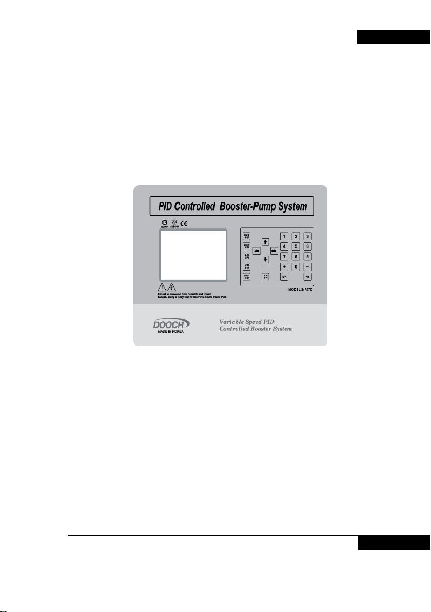
User’s Manual For Booster Pump
N747D Controller
DOOCH CO., LTD
BOOSTER PUMP SYSTEM N747D
BOOSTER PUMP SYSTEM 1
Page 2

BOOSTER PUMP SYSTEM N747D
Chapter #1 The composition and features of controller
1. Features of controller …………………… 5
2. Major Functions of controller ………… 6
Chapter #2 Key operation of user
Chapter #3 Key operation of installer
Chapter #4 Key Operation of pump operation history
3. Composition of controller ……………… 7
1. Key operation of user setting …….. 10
2. Display of user setting ……….. 10
3. Change of user setting(1) ……….. 11
4. Change of user setting(2) ……………… 15
5. Change of user setting(3) …………….. 19
1. Key operation of installer setting ……… 26
2. Display of user setting ….…….. 26
3. Change of installer setting(1) ………….. 27
4. Change of installer setting(2) ………….. 32
5. Change of installer setting(3) ……….. 36
1. Confirmation of pump operation history ….. 42
2. Confirmation of alarm history ……..…….. 43
Contents
2 BOOSTER PUMP SYSTEM
Page 3

Chapter #5 Key operation of test operation
1. Test operation key .…………………….. 46
Chapter #6 Other Keys
1. Inverter reset Key …….…………………….. 49
2. Key of Initial display ….…………………….. 49
3. Alarm display and Reaction…………………. 49
Chapter #7 Appendix
1. Control Board Arrangement and Description…. 52
2. Check items ………..……………………… 55
3. Pump Test operation …………….….……. 57
4. Emergency Operation......……………………… 58
5. RS-485 Communication .………………… 60
BOOSTER PUMP SYSTEM N747D
BOOSTER PUMP SYSTEM 3
Page 4

BOOSTER PUMP SYSTEM N747D
Chapter #1
The composition and features of controller
1. Features of controller
Functions of controller
2.
Composition of controller
3.
1. Features of controller
4 BOOSTER PUMP SYSTEM
Page 5
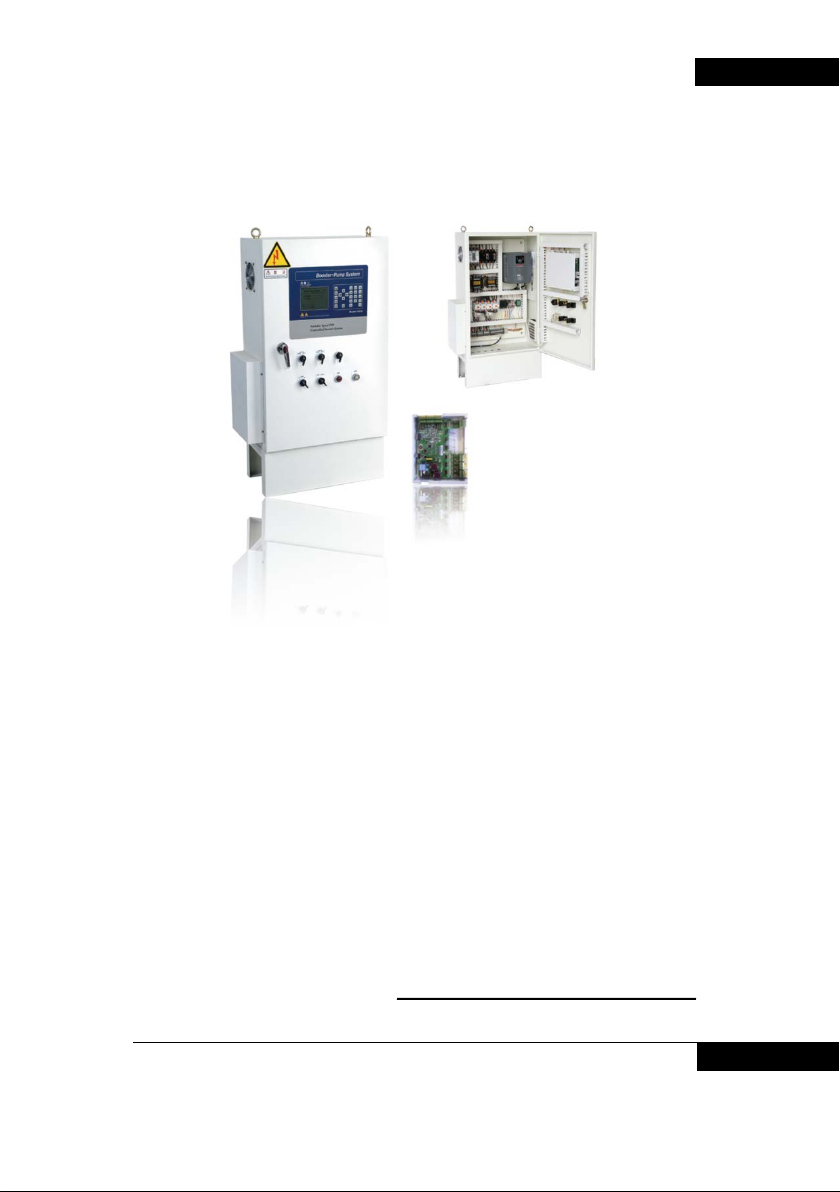
This advanced computer control device has been achieved its controlling of
pump’s RPM by inverter through the newest electronic technology, and
equipped with presumptive terminal pressure control technology and various
intelligent functions which can determine and control the pressure of water
supply according to the amount of supplied water and usage.
Up to 6 pumps can be controlled with functions generally such as; stopping
low flow using pressure tank, control, scheduled operation, warning
abnormal state, full automated sequential operation, interval shift operation,
skipping failed pump automatically, displaying operation data and data
storing
Remote controlling and monitoring functions by remote modem
communication, and easy operating for anyone by displaying of all screen
view in Korean./ English / Chinese.
2. Major functions of controller
BOOSTER PUMP SYSTEM 5
BOOSTER PUMP SYSTEM N747D
Page 6

BOOSTER PUMP SYSTEM N747D
Major function
Description
LCD Display in Korean
Easy operation and control for anyone by Korean menu.
Select display language
Select Korean(default) / English/ Chinese/ Spanish from
Control latest PID
Latest PID Control by micro processor.
Alarming high pressure
When specified pressure/time is exceeded, pump stops and
Alarming low pressure
When every pump s are operated under specified pressure
Inverter options
Operating with two inverters simultaneously
Inverter-fix type Select inverter-fix type from menu.
LCD Monitor Displaying variety information through large LCD screen.
menu.
sequential operation Operating and stopping motor sequentially.
Preventing idling In case of no water in suction piping, operating stop and
Skipping failed pump If any pump is failed, the next pump is operated skipping the
Preventing excessive
current to motor
Prevention of abnormal
high voltage
Scheduled operation. Available to vary operating conditions by time/day/month.
Self-access operation Optimized operation through self-assessment
Correction of sensor
value
Record operation data
and save
Display alarmed
description and save
Emergent operation Emergent operation by pressure switch in case controller
Shift operation After certain period of operation, main pump function is
Spare sensor Spare pressure sensor is connected, so that when one
Contact terminals by
pump
Input external analog
data
CAN communication
485 communication
alarming
failed one.
Automatic-trip in case operating current of motor is
abnormal.
Preventing abnormal high voltage by pressure switch against
to any problems in pressure sensor.
alarm is given.
even during the continuous operating, then alarm is given
( preventing low pressure).
Correcting when sensor value does not match with analog
gauge.
Record various operation data and save.
Displays various alarmed descriptions and save.
and pressure transmitter are in failure.
shifted so that pumps can be operated equally.
pressure sensor is failed, other sensor is employed
automatically to replace the function.
Outputs operation and error by pump to external contact
terminal.
Input of multi-functio nal e xt ern al analog data
Supporting CAN and RS485 communication
3. Composition of controller
6 BOOSTER PUMP SYSTEM
Page 7
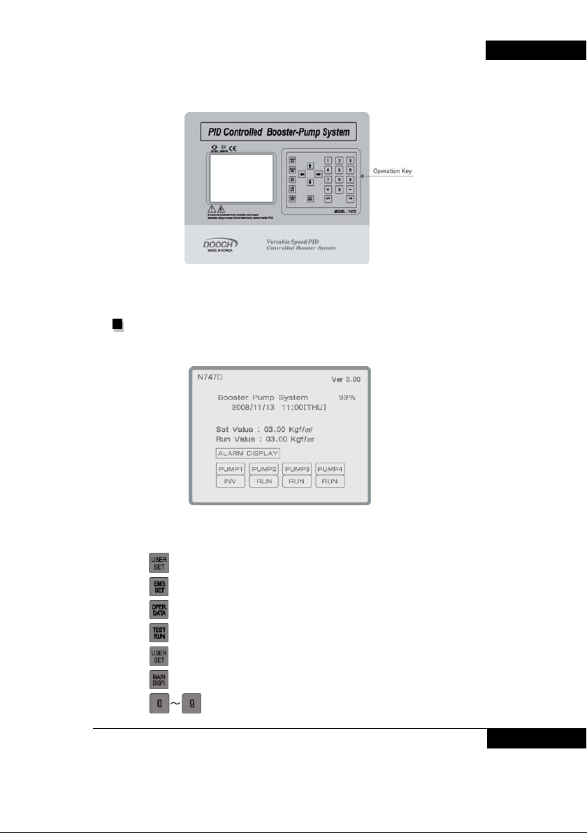
< Controller External >
Controller is consisted of LCD play and operation Keys.
- LCD Display : It displays system information.
BOOSTER PUMP SYSTEM N747D
- Operation Key : It is for data setting and checkup data.
: It is for booster system user.
: It is for booster system installer.
: It is for checking operation data.
: It is for checking motor rotation direction.
: In case of inverter fault, it is for reset inverter.
: It is for recovery to the main display.
: Setting value.
BOOSTER PUMP SYSTEM 7
Page 8

BOOSTER PUMP SYSTEM N747D
: + , - Setting value.
: It is for saving setting value and checking operation history/
alarm history
: It is for deleting operation history/alarm history
: It is for moving cursor to the menu.
8 BOOSTER PUMP SYSTEM
Page 9

BOOSTER PUMP SYSTEM N747D
Chapter #2
Key operation of user
Key operation of user setting
1.
Display of user setting
2.
3. Change of user setting(1)
Change of user setting(2)
4.
5.
Change of user setting(3)
BOOSTER PUMP SYSTEM 9
Page 10
BOOSTER PUMP SYSTEM N747D
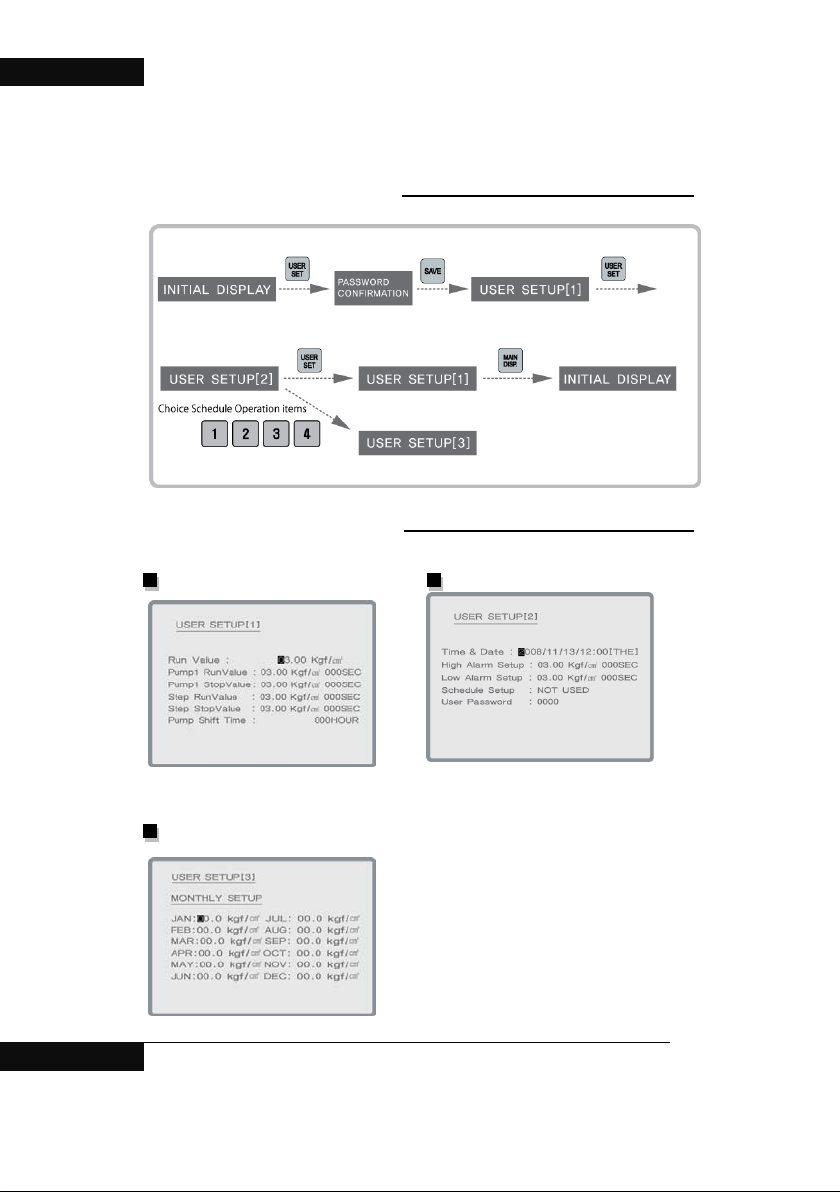
1. Key operation of user setting
2. Display of user setting
User setup display [1] User setup display [2]
User setup display [3]
- The display of User setup [3] is related with User setup [2]
10 BOOSTER PUMP SYSTEM
.
Page 11
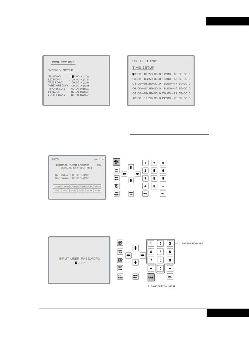
< Display of Monthly operation>
< Display of weekly operation> < Display of timely operation >
3. The change of user setup[1]
1. Press installer setup on main display
BOOSTER PUMP SYSTEM N747D
2. Input password and save (initial password is “0000”)
BOOSTER PUMP SYSTEM 11
Page 12
BOOSTER PUMP SYSTEM N747D
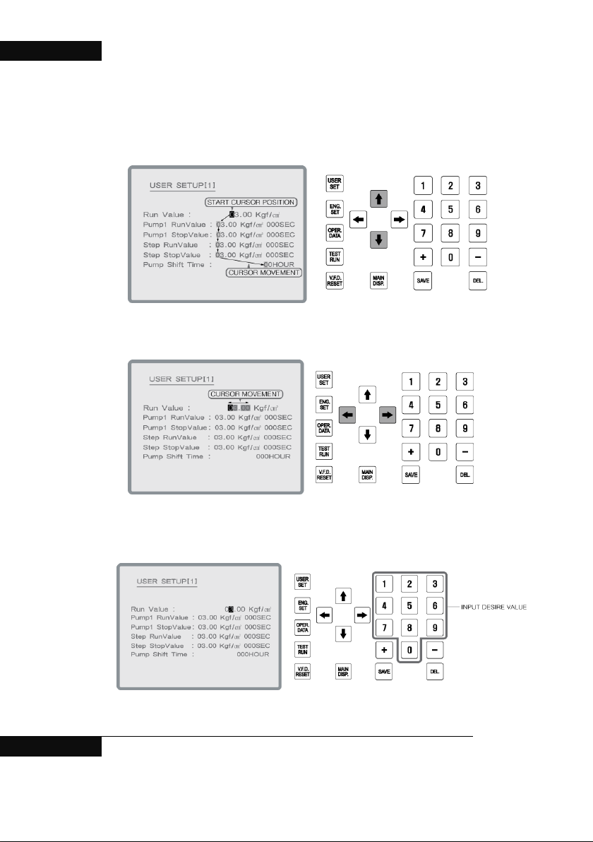
3. In user setup [1], move to desire display with cursor.
4.Move to desire display with cursor
※ Cursor can be moved to left / right.
5. Setting value can be changed by figure Keys.
12 BOOSTER PUMP SYSTEM
Page 13
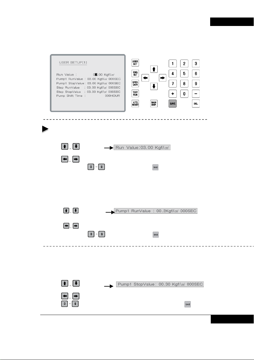
6. After setting, press “save” .
The adjustable items in the user setting [1] are as below.
- Setting pressure: Target water pressure to operate.
Change of predetermined pressure.
(Example: In case current set value is 03.00 kgf/cm² )
1. Using
2. Initially the first ‘0’ of the ’03.00’ blinks.
3. Using
4. After change using
※ Set value is not changed until input key is pressed.
※ When predetermined pressure is changed, the high pressure value becomes
setting pressure +2k gf/cm ² aut omatically.
………………………………………………………………………………………………………-
-The change of a uxi liary stop pressure
(Example: In case current set value is 00.2 kgf/cm²)
1. Using
2. Initially the first ‘0’ of the ’00.20’ blinks.
3. Using
4. After change using
- Auxiliary stop pressure : it means the pressure to stop the auxiliary pump.
When current pressure decreases hoigher than “setting pressure + auxiliary operation
pressure”, then auxiliary pump will stop. If setting pressure is 03.00 kgf/cm² and auxiliary
pressure is 00.50kgf/cm², 005 second, and current pressure is higher than 3.5kgf/cm²,
then auxiliary pump will stop after 5 seconds.
Change of auxiliary stop pre ss u re.
(Example: In case current set value is 00.30 kgf/cm² )
1. Using
2. Initially the first ‘0’ of the ’03.00’ blinks.
3. Using
4. Using
※ Set value is not changed until input key is pressed.
Key, select .
Key, select position to be changed in ‘03.00 kgf/cm² ‘.
Key, make sure to press Key.
Key, select
Key, select position to be changed in ‘00.20 kgf/cm².
Key, make sure to press Key
Key select .
Key, select the position to be changed in ’00.30 kgf/cm²’.
Key, change to required value, then make sure to press Key.
BOOSTER PUMP SYSTEM 13
BOOSTER PUMP SYSTEM N747D
Page 14
BOOSTER PUMP SYSTEM N747D
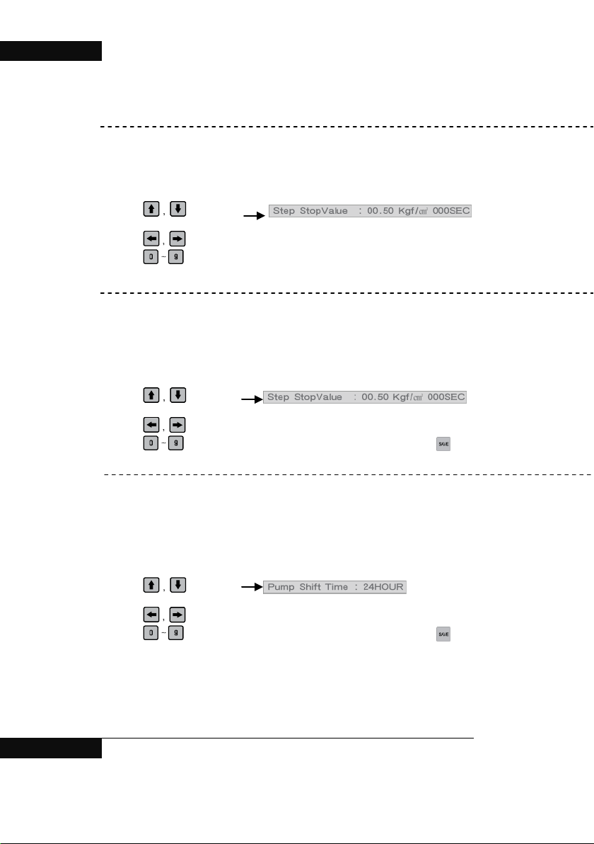
- Step operational pr es sure (E m erg en t oper a ti on al pres s ur e) :
When “step operation 1” has been set by user or inverter error occurs, pump runs if
“setting pressure-current pressure” is lower than specified emergent operating pres sure.
Change of step operational pressure.
(Example: In case current set value is 00.50 kgf/cm² )
1. Using
2. Initially the first ‘0’ of the ’00.50’ blinks.
3. Using
4. Using
※ Setting value will not be changed until input key is not pressed.
step stop pressure (emergent stop pressure) :
When “step operation 1” has been set by user or inverter error occurs, pump runs if
“setting pressure-current pressure” is lower than specified emergent operating pres s u re.
Change of stepl stop pressure.
(Example: In case current set value is 00.50 kgf/cm² )
1. Using
2. Initially the first ‘0’ of the ’00.50’ blinks.
3. Using
4. Using
※ Set value is not changed until input key is pressed.
- Shift time of main pump :
When the specified time as the shift time of main pump is over, the main pump is
changed. However, while the pump is in operating, it s operating mode is maintained until
2:00am then shifted forcibly. Setting is available up to ‘99’, and when setting is in ‘00’, the
main pump is shifted whenever inverter stops.
Change of main pump shift time
(Example: In case current set value is 24 hours.)
1. Using
2. Initially the first ‘2’ of the ’24’ blinks.
3. Using
4. Using
※ Set value is not changed until input key is pressed.
※ In case of forced shift, all pump stops for a while.
Key, select .
Key, select the position to be changed in ’00.50 kgf/cm²’.
Key, change to required value, then make sure to press Key.
Key, select .
Key, select the position to be changed in ’00.50 kgf/cm²’.
Key, change to required value, then make sure to press Key.
Key, select .
Key, select the position to be changed in ’24’.
Key, change to required value, then make sure to press Key.
14 BOOSTER PUMP SYSTEM
Page 15
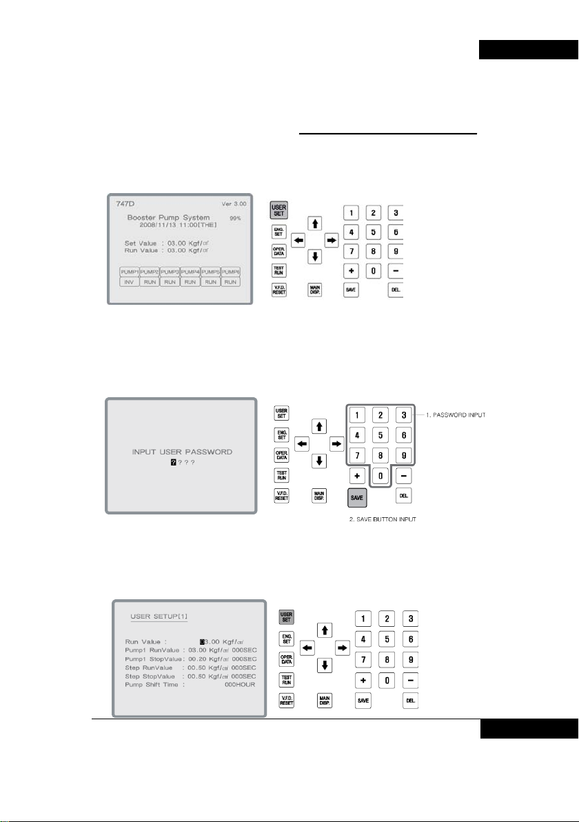
4. The change of user setup[2]
1. . Press user setup on main display.
2. . Input password and save (initial password is “0000”)
BOOSTER PUMP SYSTEM N747D
3. Press user setup key on user setting [1].
BOOSTER PUMP SYSTEM 15
Page 16
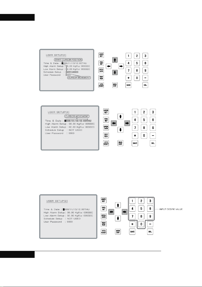
BOOSTER PUMP SYSTEM N747D
4. In user setup [2], move to desire display with cursor.
5. Setting value can be changed by figure Keys.
16 BOOSTER PUMP SYSTEM
Page 17
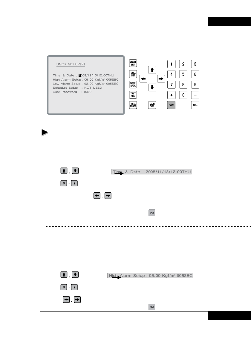
6. After setting, press “save”.
Changeable items in user setting [2] are as below.
- Time setting : 2008/11/13 12:20 Thursday
It displays in the order of year/month/day time :minute days, and if it does not
matched with present time then adjust it.
Adjust of time settings
( Example: In case of change “2008/11/13 12:00 Thursday” to “2008/11/13 24:00
Thursday”)
1. Using
2. The first ‘2’ of the ‘2008/11/13 12:00 Thursday’ blinks.
3. Using
When no change is required or in case of wrong input, it’s available to move to
required position using
The last number means day of the week as below;
1 : Mon 2 : Tue 3 : Wed 4 : Thurs 5 : Fri 6 : Sat 7 : Sun
4. After changing to required value, make sure to press
※ Set value is not changed until input key is pressed.
- Setting high pressure alarm : OO.OOkgf/cm² OOOsecond
When water pressure sustains at above than specified pressure (OO.OO) for more
than OOO seconds, alarm is to be given.
Change settings of high pressure alarm
(Example: in case of to change 05.00 kgf/cm² 005 seconds to 04.00 kgf/cm²
003seconds)
1. Using
2. Initially the first ‘0’ of the ’05.00 kgf/cm² 005 second’ blinks.
3. Using
In case no change is required or wrong input, moving to desired position is available
by using
4. After changing to required value, make sure to press
Key, select .
Key, enter in the order of 2,0,0,8,1,1,1,3,1,2,0 and 0 (Thurs).
Key.
Key.
Key, select .
Key, enter in the order of 0, 4, 0, 0, 0, 0 and 3.
Key.
Key.
BOOSTER PUMP SYSTEM 17
BOOSTER PUMP SYSTEM N747D
Page 18
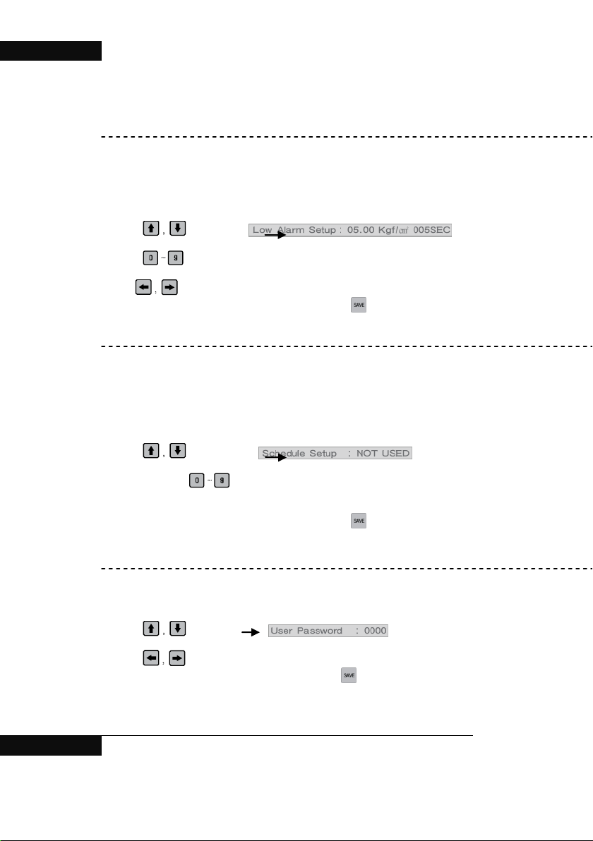
BOOSTER PUMP SYSTEM N747D
※ Set value is not changed until input key is pressed.
※ When setting pressure of user setting [1] is changed, setting pressure of the high
pressure alarm settings is automatically set as +2kgf/cm².
- Setting of low pressure alarm : OO.OOkgf/cm² OO Oseconds .
When water pressure sustains at lower than specified pressure (OO.OO) for more
than OOO seconds, alarm is to be given.
Change of lower pressure alarm setting
(Example: in case of to change 00.00 kgf/cm² 005seconds to 00.20 kgf/cm² 005seconds)
1. Using
2. Initially the first ‘0’ of the ’ 00.00 kgf/cm² 005 seconds’ blinks.
3. Using
In case no change is required or wrong input, moving to desired position is available by
using Key.
4. After changing to required value, make sure to press
※ Set value is not changed until input key is pressed.
- Setting of scheduled operation : Available to select among No use / Monthly
operation / Weekly operation / Operation by time frame. Initial setting is ‘No use’, and
operation method can be selected with 0~3 number keys. Each number stands for;
0 : No use 1 : Monthly operation 2 : Weekly operation 3: operation by time frame
Change setting of scheduled operation.
(Example: To change “scheduled operation : no use” to “ scheduled operation : operation
by time frame”)
1. Using
2. “No use” blinks.
3. Enter “3” among
(0 : No use 1 : Monthly operation 2 : Weekly operation 3: operation by time
frame )
4. After changing to required value, make sure to press
※ Set value is not changed until input key is pressed.
5. To use scheduled operation, the settings shall be changed in “ user operation [3].
Refer to the changes in “user operation [3]” for detail information.
- Change of user password : N747D is designed to set password in order to preven t
others from tampering settin gs wi tho ut aut horization. Initial password is set as 0000.
Change of user password
(Example: To change “use password : 0000” to “ ser password : 1234”)
1. Using
2. User password : Initially the first ‘0’ of the ’0000’ blinks.
3. Using
4. After changing to required value, make sure to press
※ Set value is not changed until input key is pressed.
Key, select .
Key, enter in the order of 0, 0, 2, 0, 0, 0 and 5 .
Key.
Key, select .
Keys.
Key.
Key, select .
Key, enter 1, 2, 3, 4.
Key.
18 BOOSTER PUMP SYSTEM
Page 19
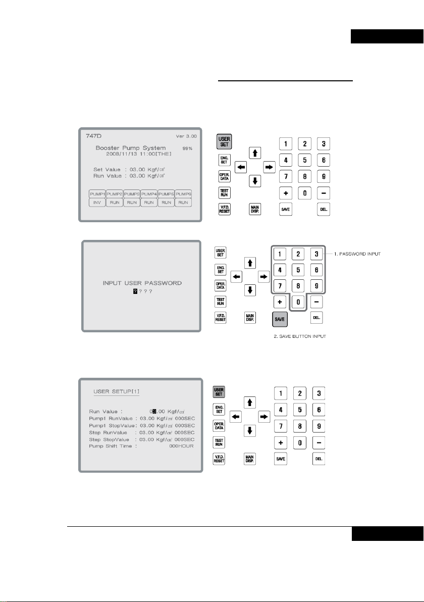
5. The change of user setup[3]
1. Press user setup on main display.
Input password and save (initial password is “0000”)
BOOSTER PUMP SYSTEM N747D
2. .
3. Press user setup key on user setting [1].
BOOSTER PUMP SYSTEM 19
Page 20
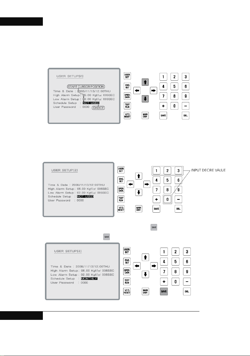
BOOSTER PUMP SYSTEM N747D
4. In user setup [2], move to schedule setup with cursor.
5. Choose desire figure from “0” to “3”.
0 : Not used 1 : Monthly operation 2 : Weekly operation 3 : Timely operation
6. After changing to operation setup, make sure to press
Set value is not changed until
20 BOOSTER PUMP SYSTEM
Key.
input key is pressed.
Page 21
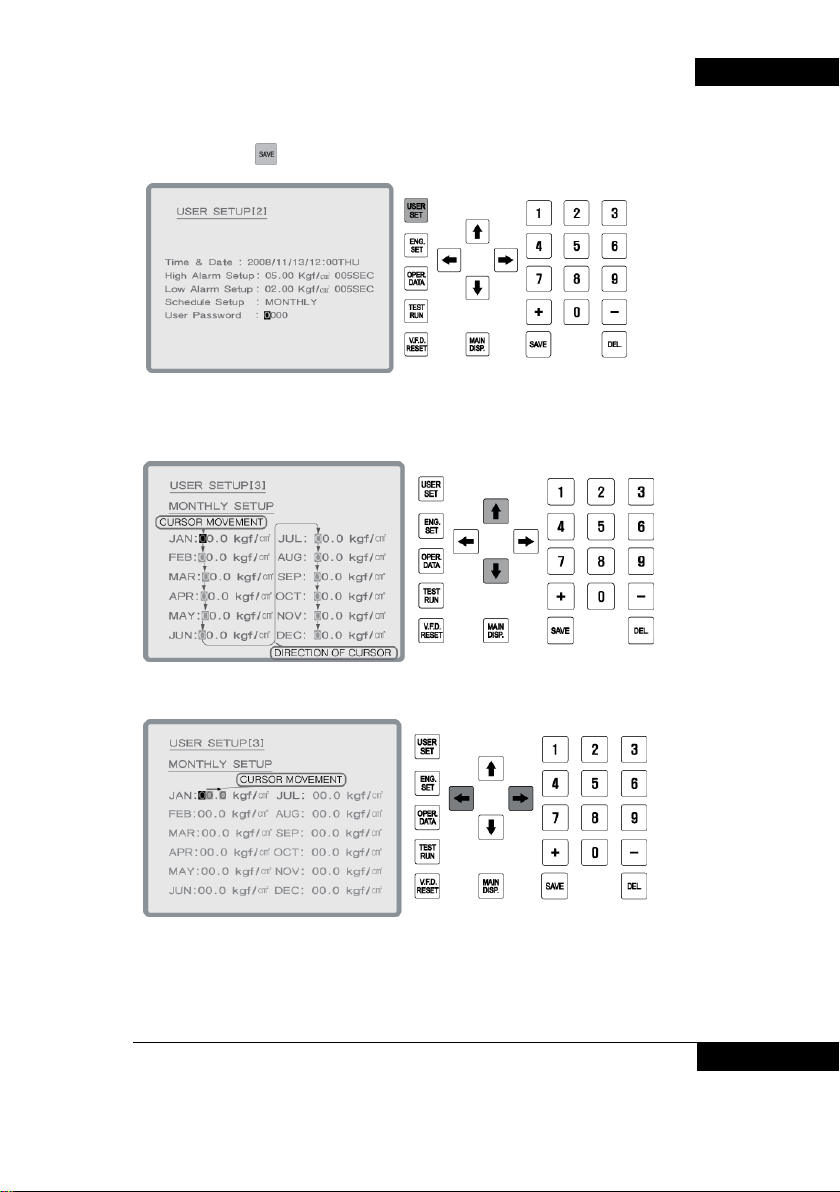
7. After pressing Key, press user setup to move user setup [3].
8. In user setup[3], choose desire menu with cursor..
BOOSTER PUMP SYSTEM N747D
9.
BOOSTER PUMP SYSTEM 21
Page 22
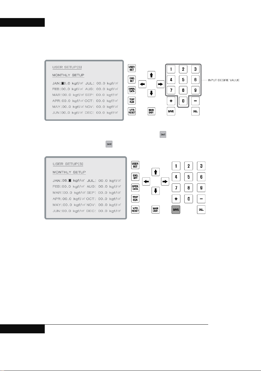
BOOSTER PUMP SYSTEM N747D
10. Change the desire value with figure Keys.
11. After changing to o pe ration setup, make sure to press Key.
Set value is not changed until
.
input key i s pressed.
22 BOOSTER PUMP SYSTEM
Page 23
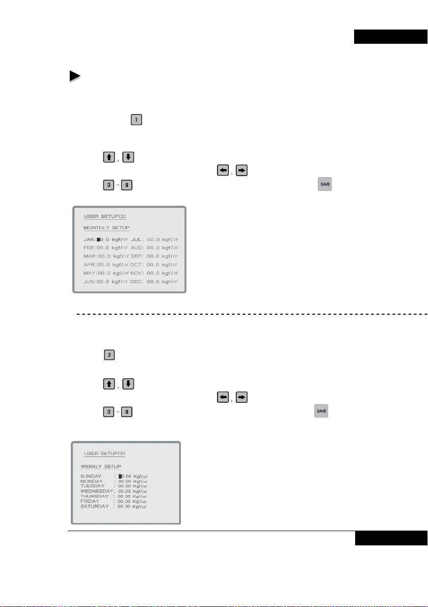
Changeable items in user settings [3] as below.
- Monthly scheduled operation. : Any operation by monthly can be scheduled and
executed.
To change settings, select monthly operation from the scheduled operation in “user
setting [2] using
and change it.
Monthly scheduled operation.
1. Using
2. Select required positi o n in the item s usi ng
3. Using
※ Set value is not changed until input key is pressed.
<Screen configuration of monthly operation>
- Weekly scheduled operation. : Any operation by weekly can be scheduled and
executed.
To change settings, select weekly operation from the scheduled operation in “user setting
[2] using
it.
Weekly scheduled operation.
1. Using
2. Select required positi o n in the item s usi ng
3. Using
※ Set value is not changed until input key is pressed.
Key, then press ‘user setting button’ to move to “user setting [3]
Key, select item to be set.
Key.
Key, change to required value, then make sure to press Key.
Key, then press ‘user setting button’ to move to “user setting [3] and change
Key, select item to be set.
Key.
Key, change to required value, then make sure to press Key.
< Screen configuration by day operation >
BOOSTER PUMP SYSTEM 23
BOOSTER PUMP SYSTEM N747D
Page 24
BOOSTER PUMP SYSTEM N747D
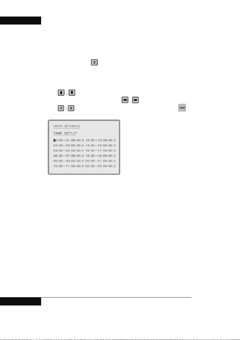
Scheduled oper ation by time frame. : Any operation by time frame can be
scheduled and executed.
To change settings, select by-time frame operation from the scheduled operation in
“user setting [2] using
setting [3] and change it.
Scheduled oper ation by time frame.
1. Using
2. Select required position in the items using
3. Using
※ Set value is not changed until input key is pressed.
< Screen configuration by time frame operation >
Key, select item to be set.
Key, change to required value, then make sure to press Key.
Key, then press ‘user setting button’ to move to “user
Key.
24 BOOSTER PUMP SYSTEM
Page 25

Chapter #3
Key operation of installer
1. Key operation of installer setting
2. Display of user setting
3. Change of installer setting(1)
4. Change of installer setting(2)
5. Change of installer setting(3)
BOOSTER PUMP SYSTEM N747D
BOOSTER PUMP SYSTEM 25
Page 26
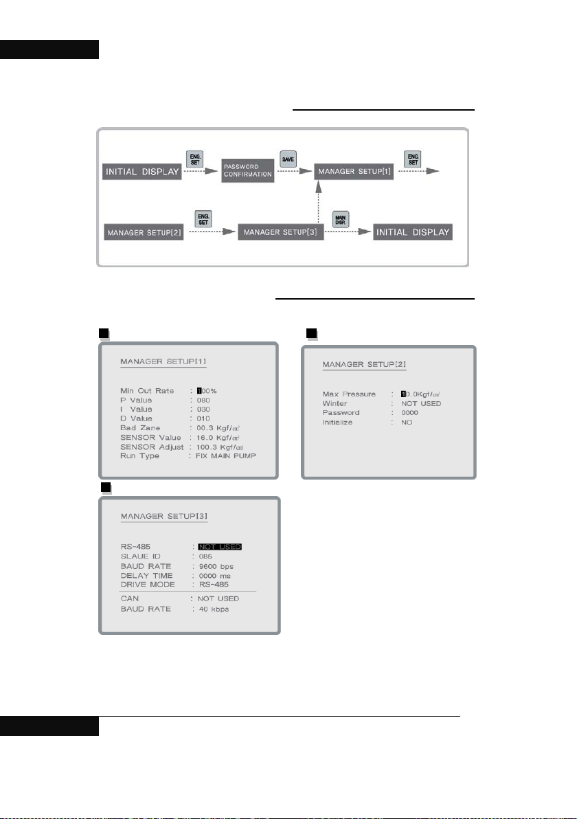
BOOSTER PUMP SYSTEM N747D
1. Installer Setup Key
2. Display of Installer setup
Display of installer setup[1] Display of installer setup[2]
Display of installer setup[[3]
26 BOOSTER PUMP SYSTEM
Page 27
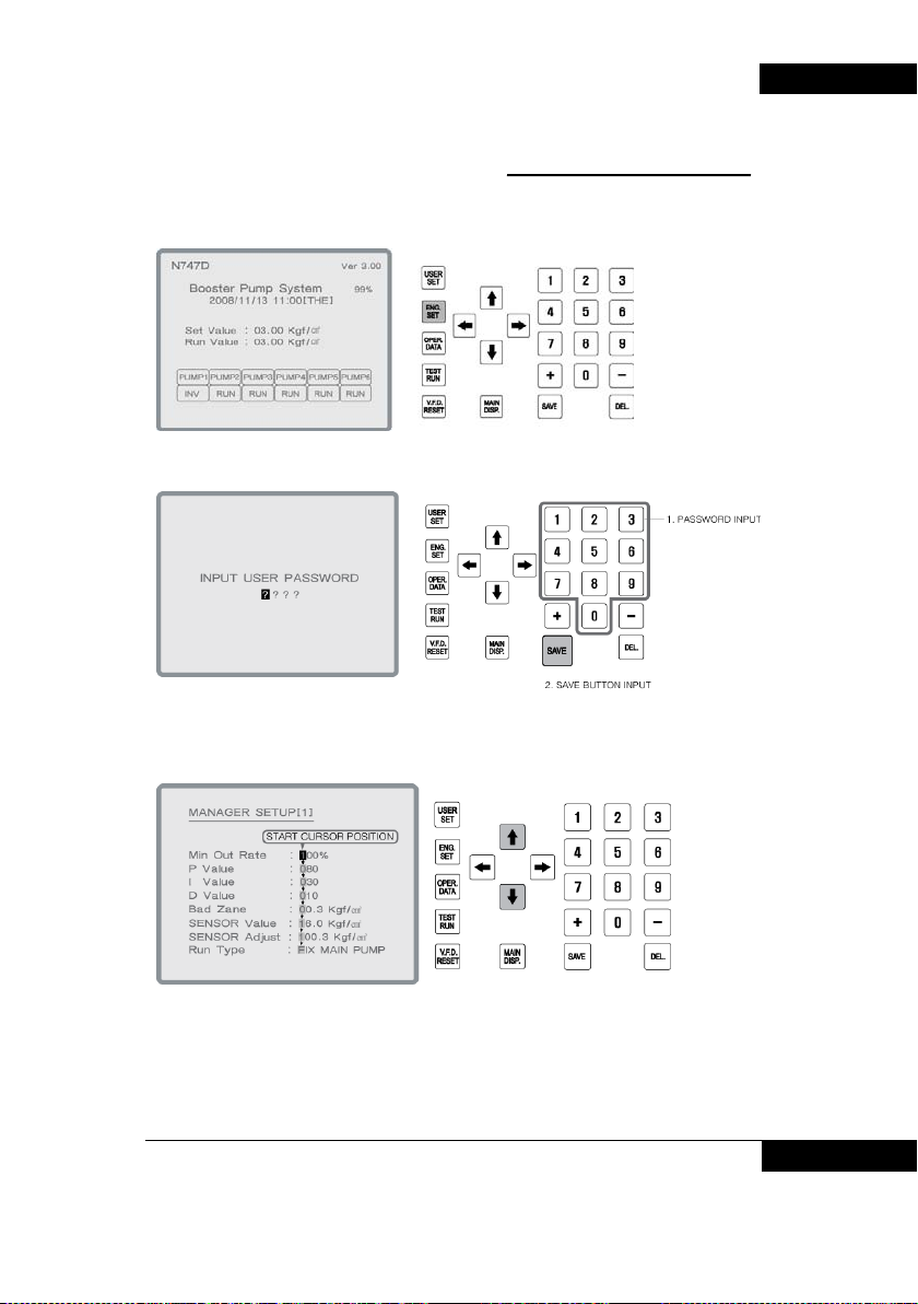
3. The change of installer setup[1]
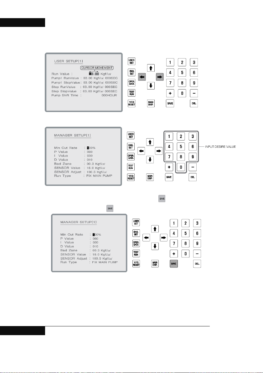
1. Press ENG SET key on main display.
2. . Input password and save (initial password is “0000”))
3. In installer setup [2], move to desire item with cursor.
BOOSTER PUMP SYSTEM N747D
BOOSTER PUMP SYSTEM 27
Page 28
BOOSTER PUMP SYSTEM N747D
4.
5. Setting value can be changed by figure Keys.
6. After changing to operation setup, make sure to press Key.
Set value is not changed until
input key i s pressed.
28 BOOSTER PUMP SYSTEM
Page 29
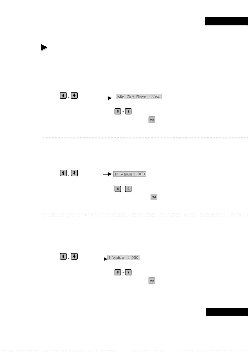
Changeable items in user settings [1] as below.
- The minimum operation rate of inverter
Set the minimum inverter output in %. When inverter operates, set 60Hz at
100%, or set value is 50% then operate from 30Hz.
Change of the minimum operation rate if inverter.
(Example: To change 50% to 60%)
1. Using
2. Initially the first ‘0’ of the ’050’ blinks.
3. Enter in order of 0, 6 and 0 using
4. After changing to required value, make sure to press
※ Set value is not changed until input key is pressed.
- Proportional factor ( P ) : It is a proportional factor in PID control variables.
Range : 1 ~ 100
Change of proportional factor (P) settings.
(Example: In case of to change 80 to 90)
1. Using
2. Initially the first ‘0’ of the ’080’ blinks.
3. Enter in order of 0, 9 and 0 using
4. After changing to required value, make sure to press
※ Set value is not changed until input key is pressed.
- Constant of integration ( I ) : It is a constant of integration in PID control
variables.
Range : 1 ~ 100
Change of constant of integration ( I ) settings.
(Example: In case of to change 30 to 40)
1. Using
2. Initially the first ‘0’ of the ’030’ blinks.
3. Enter in order of 0, 4 and 0 using
4. After changing to required value, make sure to press
※ Set value is not changed until input key is pressed.
Key, select .
Key.
Key.
Key, select .
Key.
Key.
Key, select .
Key.
Key.
BOOSTER PUMP SYSTEM N747D
BOOSTER PUMP SYSTEM 29
Page 30
BOOSTER PUMP SYSTEM N747D
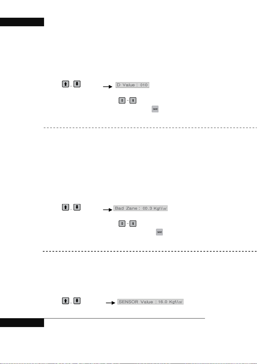
- Constant of differential ( D ) : : It is a constant of differential in PID control
variables.
Range : 1 ~ 100
Change of constant of differential ( I ) settings. (Example: In case of to change 10 to
20)
1. Using
2. Initially the first ‘0’ of the ’010’ blinks.
3. Enter in order of 0, 2 and 0 using
4. After changing to required value, make sure to press
※ Set value is not changed until input key is pressed.
- Dead zone : It’s the detection range of non-flow. It works when only one
inverter operates.
I.e., if only one pump operates and current state of that current pressure >
( setting pressure – Dead zone) is sustained for more than 20 seconds, inverter
decelerates in order to inspect the state of non-flow. Even if it decelerates, when
current pressure > (settins pressure – Dead zone), it stops.
Range : 0.0 ~ 2.0
Change of dead zone settings
(Example: In case of to change 0.3kgf/cm² to 0.4kgf/cm²)
1. Using
2. Initially the first ‘0’ of the ’003’ blinks.
3. Enter in order of 0, 0 and 4 using
4. After changing to required value, make sure to press
※ Set value is not changed until input key is pressed.
- Maximum sensor value : Enter the maximum value as far as pressure sensor
measures.
Range : 1.0 ~ 25.0
Change of maximum sensor value.
(Example: in case of to change 16.0kgf/cm² to 20.0kgf/cm²)
1. Using
2. Initially the first ‘1’ of the ’16.0’ blinks.
Key, select
Key.
Key.
Key, select .
Key.
Key.
Key, select .
30 BOOSTER PUMP SYSTEM
Page 31
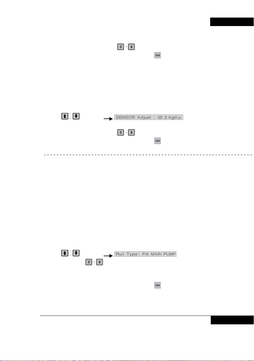
3. Enter in order of 2, 0 and 0 using Key.
4. After changing to required value, make sure to press
※ Set value is not changed until input key is pressed.
- Corrected value of sensor : This function corrects the deviation between the
analog or digital pressure gauge in the piping and current pressure indicated in
panel LCD
Range : 1.0 ~ -1.0
Change of sensor maximum value settings.
(Example: in case of to change 16.0kgf/cm² to 20.0kgf/cm²)
1. Using
2. Initially the first ‘0’ of the ’00.3” blinks.
3. Enter in order of 0, 0 and 4 using
4. After changing to required value, make sure to press
※ Set value is not changed until input key is pressed.
- Operating method : To set operation method of pump.
1 : Operating by fixed-inverter
2 : sequential 1 operation
3 : sequential 2 operation
Change of operation method settings.
(Operating method: Example – In case of change main pump fixed method to
sequential 2 operation)
1. Using
2. Enter 3 with using
(1: Operating by fixed-inverter 2: Sequential 1 operation 3: Sequential 2
operation)
3. After changing to required value, make sure to press
※ Set value is not changed until input key is pressed.
Key, select .
Key.
Inverter is fixed for one pump operation, and when all pumps stop,
move the inverter .
Sequential operation by pressure sensor without inverter( Automatically
switched when inverter failure. )
Sequential operation by pressure switch without inverter or pressure sensor
(manually switched).
Key, select .
Key .
Key.
Key.
Key.
BOOSTER PUMP SYSTEM N747D
BOOSTER PUMP SYSTEM 31
Page 32
BOOSTER PUMP SYSTEM N747D
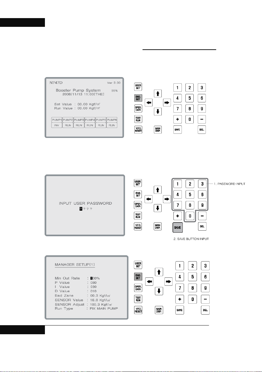
4. The change of installer setup[2]
1. Press ENG SET key on main display.
.
2. Input password and save (initial password is “0000”)
3. Press ENG SET on installer setup[1].
32 BOOSTER PUMP SYSTEM
Page 33
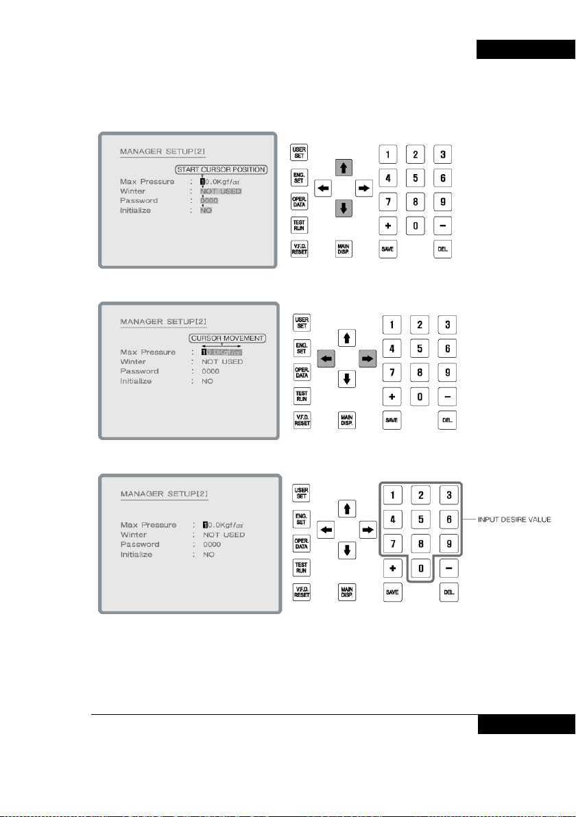
4. In installer setup [2], move to desire item with.
BOOSTER PUMP SYSTEM N747D
5.
6. Setting value can be changed by figure Keys.
BOOSTER PUMP SYSTEM 33
Page 34
BOOSTER PUMP SYSTEM N747D
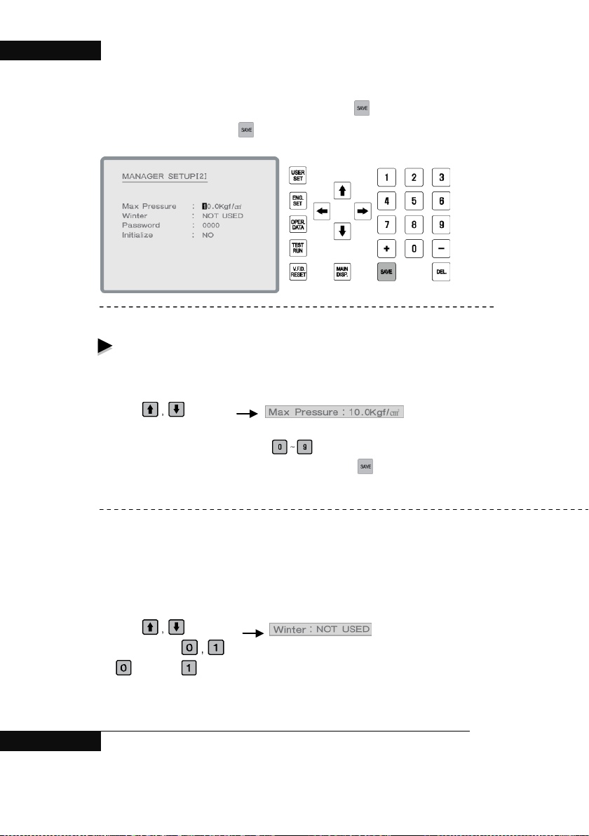
7. After changing to operation setup, make sure to press Key.
Set value is not changed until
input key i s pressed.
The changeable items in installer setting [2] are as below;
- Pump maximum pressure : Entering the maximum pressure of pump.
Changing of pump maximum pressure settings.
(Example: In case of to change 10.0 to 20.0)
1. Using
2. Initially the first ‘1’ of the ’10.0’ blinks.
3. Enter in order of 2, 0 and 0 using
4. After changing to required value, make sure to press
※ Set value is not changed until input key is pressed.
- Preventing frozen rupture : In order to prevent frozen rupture in cold season, if
all pumps does not operate for one minute at below -1°C, main pump operates in
15Hz for 15 seconds then stops. After stopping, the main pump is transferred to
next pump and operates as same condition in turns.
Change prevention of frozen rupture setting.
(Example: In case of change “No use” to “Use”. )
1. Using
2. Enter by using
: No use, : Use
3. After changing to required value, make sure to press c Ke y.
※ Set value is not changed until input key is pressed.
Key, select .
Key.
Key.
Key, select .
Key.
34 BOOSTER PUMP SYSTEM
Page 35
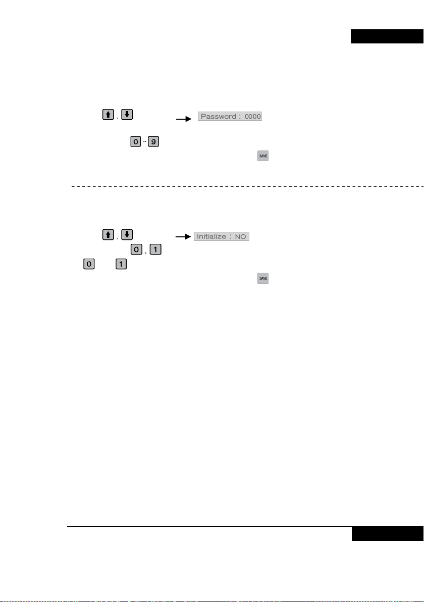
- Setting of installer’s password : Changing installer ’s password.
Change of installer’s password
(Example: To change “Installer ’s password : 0000" to “User ’s password:1234”)
1. Using
2. User’s password : Initially the first ‘0’ of the ’000’ blinks.
3. Enter by using
4. After changing to required value, make sure to press
※ Set value is not changed until input key is pressed.
- System initializing : Initialize setting values to ex-factory value.
Change setting of system initialization.
(Example: In case to change “No” to “Yes ”.)
1. Using
2. Enter by using
: No : Yes
3. After changing to required value, make sure to press
※ Set value is not changed until input key is pressed.
Key, select .
Key.
Key.
Key, select .
Key.
Key.
BOOSTER PUMP SYSTEM N747D
BOOSTER PUMP SYSTEM 35
Page 36
BOOSTER PUMP SYSTEM N747D
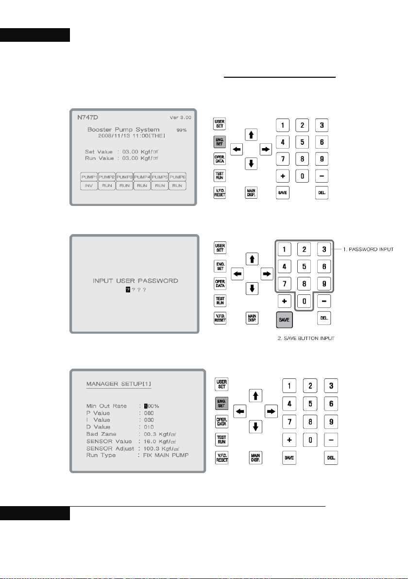
5. The change of installer setup[3]
1. Press ENG SET key on main display .
2. . Input password and save (initial password is “0000”).
3. Press ENG SET on installer setup[1].
36 BOOSTER PUMP SYSTEM
Page 37
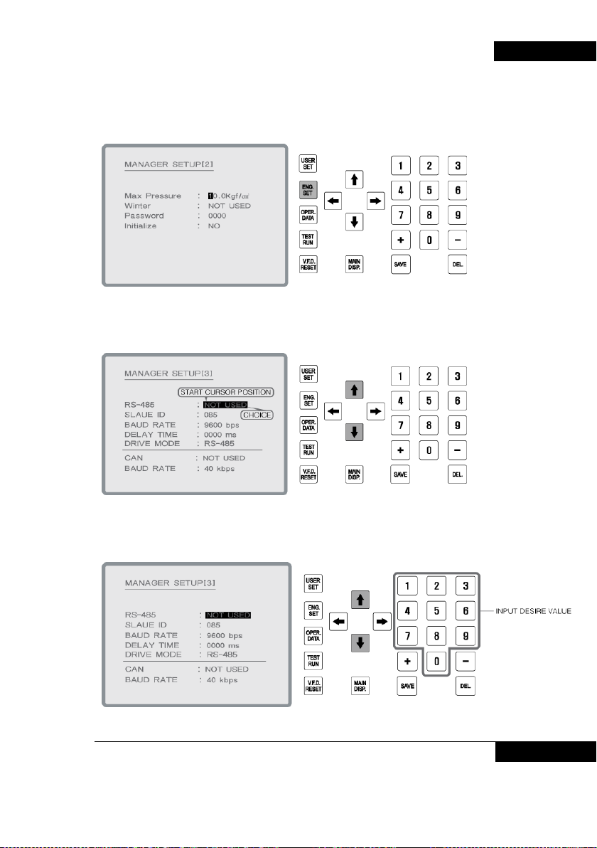
4. Press ENG SET on installer setup[2].
5. In installer setup [3], move to desire item with cursor..
BOOSTER PUMP SYSTEM N747D
6. Setting value can be changed by figure Keys.
BOOSTER PUMP SYSTEM 37
Page 38
BOOSTER PUMP SYSTEM N747D
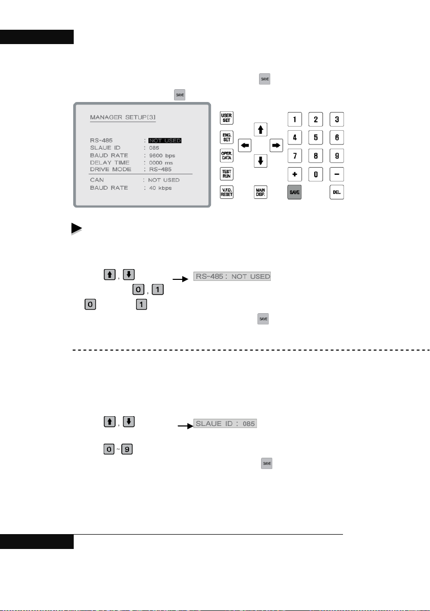
7. After changing to operation setup, make sure to press Key.
Set value is not changed until
input key i s pressed.
The changeable items in user setting [3] are as below;
- RS485 : Select whether to use RS485communication or not.
Change of RS485 setting.
(Example: In case to change “No use” to “Use”.)
1. Using
2. Enter by using
: No use, : Use
4. After changing to required value, make sure to press
※ Set value is not changed until input key is pressed.
- Slave ID : Set Slave ID.
Range : 1 ~ 255
Change setting of Slave ID.
(Example: In case of to change 85 to 96)
1. Using
2. Initially the first ‘0’ of the ’085’ blinks.
3. Using
4. After changing to required value, make sure to press
※ Set value is not changed until input key is pressed.
- BAUD RATE : Select communication speed.
(0: 1200bps 1: 2400bps 2: 4800bps 3: 9600bps 4: 19200bps)
Key, select .
Key.
Key.
Key, select .
Key, enter by the order of 0, 9 and 6.
Key.
38 BOOSTER PUMP SYSTEM
Page 39
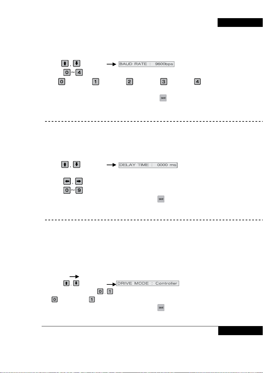
Change setting of BAUD RATE
(Example: In case of to change 9600bps to 1200bps)
1. Using
2. Using
19200bps
3. After changing to required value, make sure to press
※ Set value is not changed until input key is pressed.
- DELAY TIME : Set delay time of communication responding.
Range : 0 ~ 9999
Change DELAT TIME settings
(Example: In case of to change 0 to 20)
1. Using
2. Initially the first ‘0’ of the ’0000ms’ blinks.
3. Using
4. Using
5. After changing to required value, make sure to press
※ Set value is not changed until input key is pressed.
- DRIVE MODE: Setting for operation order .
Controller : It is operated by Start/Stop switch on panel.
RS-485 : It is operated by 485 communication
※ RS485 can be used by setting in DRIVE MODE.
※ In case of RS-485, It can’t operated by Start/Stop switch on panel.
The change of DRIVE MODE setting
(Controller RS-485)
1. Using
2. Input setting mode with
: Controller, : RS-485
5. After changing to required value, make sure to press
※ Set value is not changed until input key is pressed
Key, select .
Key, select communication speed to be changed..
: 1200bps, : 2400bps, : 4800bps, : 9600bps, :
Key.
Key, select .
Key, select the position to be changed in ‘0000 ms’.
Key, enter by order of 0, 0 and 2.
Key.
Key, select .
Key.
Key.
BOOSTER PUMP SYSTEM N747D
BOOSTER PUMP SYSTEM 39
Page 40
BOOSTER PUMP SYSTEM N747D
- CAN : Select whether to use CAN communication or not.
Change CAN setting CAN .
(Example: To change “No use” to “Use” )
1. Using
2. Enter using
: No use, : Use
3. After changing to required value, make sure to press
※ Set value is not changed until input key is pressed.
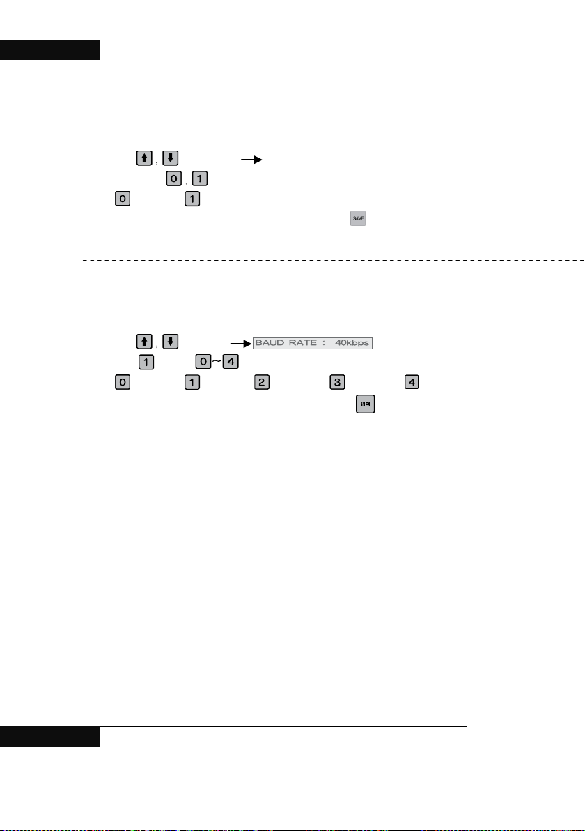
- BAUD RATE : Select communication speed.
( 0 : 40kbps 1 : 50kbps 2 : 100kbps 3 : 200kbps 4: 250kbps )
Change setting of BAUD RATE.
(Example: In case of to change 40kbps to 50kbps)
1. Using
2. Enter
: 40kbps, : 50kbps, : 100kbps, : 200kbps, : 250kbps
Key, select. CAN : NOT USED
Key.
Key.
Key, select .
among Keys.
3. After changing to required value, make sure to press
※ Set value is not changed until input key is pressed.
40 BOOSTER PUMP SYSTEM
Key.
Page 41

BOOSTER PUMP SYSTEM N747D
Chapter #4
Operation History Key
1. Confirmation of pump operation history
2. Confirmation of alarm history
BOOSTER PUMP SYSTEM 41
Page 42
BOOSTER PUMP SYSTEM N747D
1. Confirmation of pump operation history
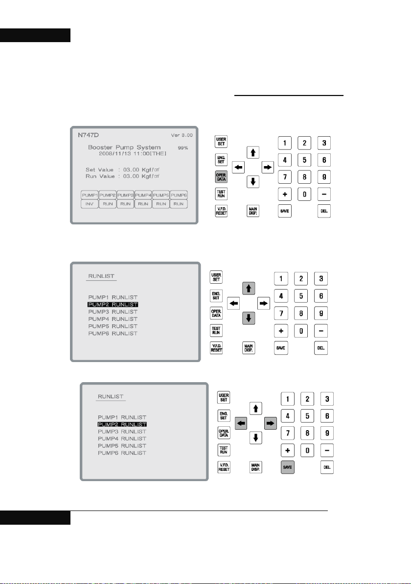
1. Press operation Data key on main display.
2. In operation data, move to desire menu with cursor.
42 BOOSTER PUMP SYSTEM
Page 43
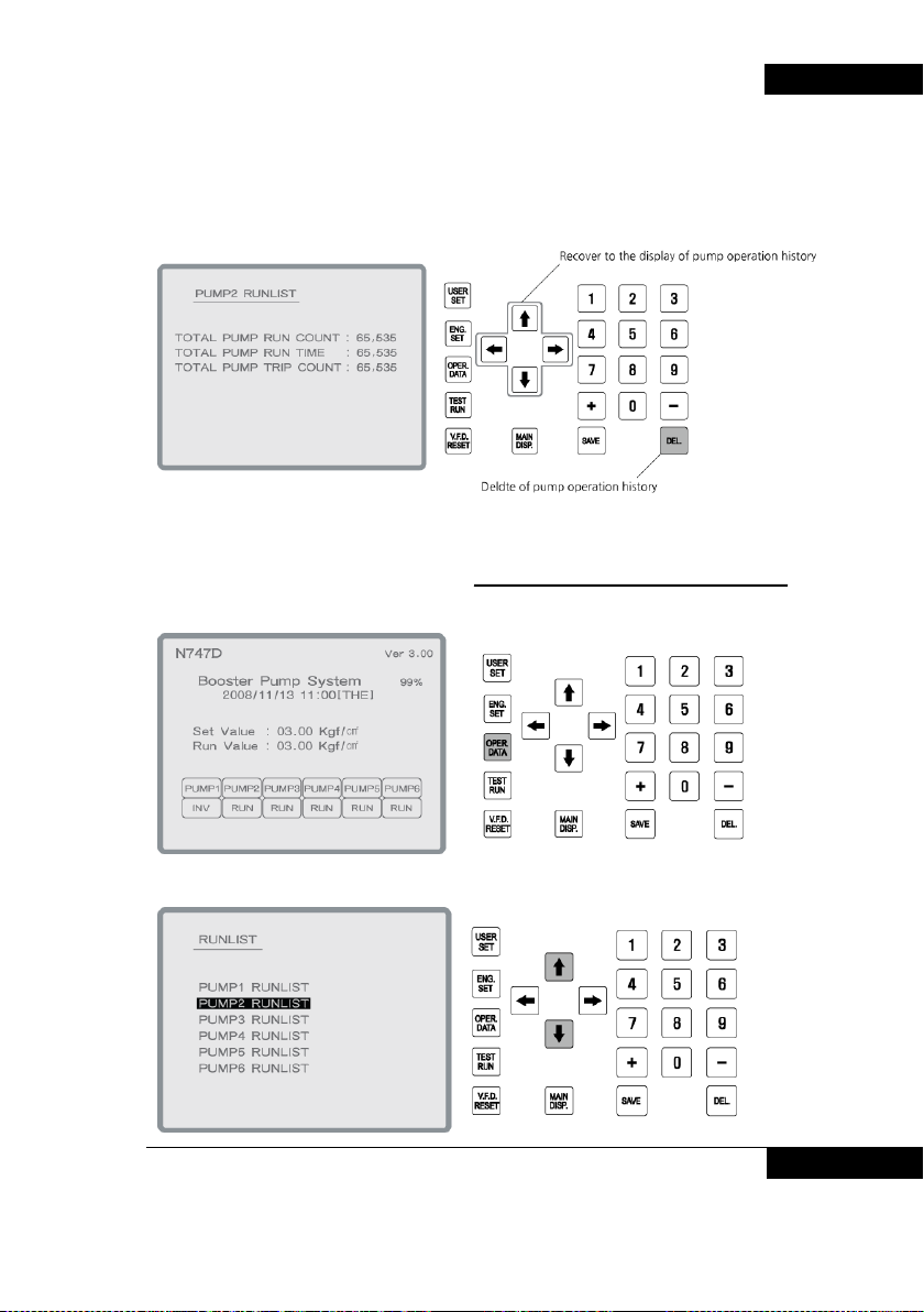
3. It shows pump operation history.
If you want to delete all pump operation history, press Del key.
2. Confirmaton of alarm history
1. Press operation Data key on main display
BOOSTER PUMP SYSTEM N747D
2. Press operation data key on operation data display.
BOOSTER PUMP SYSTEM 43
Page 44
BOOSTER PUMP SYSTEM N747D
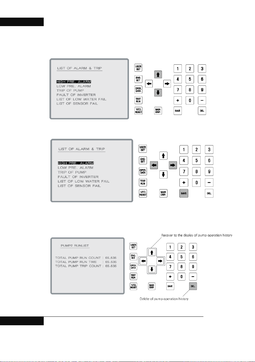
3. In alarm history display, move to desire menu with cursor
4.
5. It display alarm history.
- It shows latest 10 alarm history..
- If you want to delete all alarm history, press DEL key.
44 BOOSTER PUMP SYSTEM
Page 45

Test Operation Keys of test operation
BOOSTER PUMP SYSTEM N747D
Chapter #5
BOOSTER PUMP SYSTEM 45
Page 46
BOOSTER PUMP SYSTEM N747D
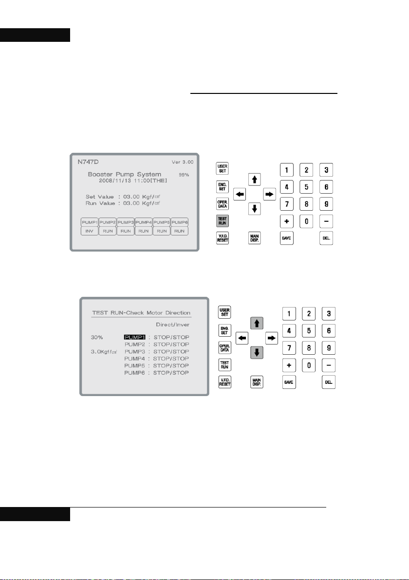
Test Operation Key
It is used for checking direction of motor rotation.
After turning off the STOP/START switch on panel, please operate this function.
1. Press Test Run key on main display..
2. In the test run display, Choose desire pump with cursors.
46 BOOSTER PUMP SYSTEM
Page 47
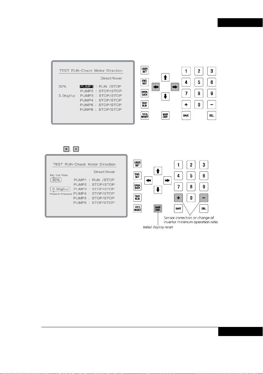
3. Use left/right cursor to select pump operation method.
4. Using Key, change the sensor correction value and Min operation ratio.
BOOSTER PUMP SYSTEM N747D
BOOSTER PUMP SYSTEM 47
Page 48

BOOSTER PUMP SYSTEM N747D
Chapter #6
Other Keys
48 BOOSTER PUMP SYSTEM
Page 49
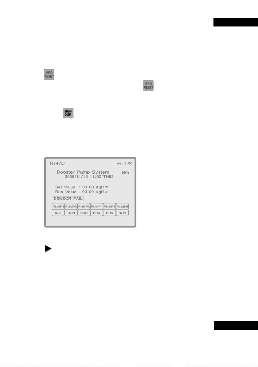
1. Inverter reset Key
Key is used to re-start inverter in inverter error state.
BOOSTER PUMP SYSTEM N747D
Up to 2 sets of inverters can be used, and pressing
trouble among two inverters (Two inverters are optional)
Key resets the inverter in
2. Main screen Key
Pressing Key enables to move to initial screen.
3. Alarm display and reaction
When alarm is given, buzzer sounds and lamp blinks. At the same time, the alarm notes
are displayed on LCD screen. To stop the buzzer, just press any key of the controller
keys. Lamp keeps blinking until the root cause of alarming is fully cleared.
Displaying items on LCD screen when alarm is given;
1. No water in the pipe line - Alarming low level
2. Motor overheating P1 TRIP - Motor overloaded
3. Sensor is abnormal - Sensor trouble
4. Inverter is abnormal (In emergent operating) - Inverter trouble.
5. Pressure is too high - High pressure alarm
6. Pressure is too low - Low pressure alarm
BOOSTER PUMP SYSTEM 49
Page 50

BOOSTER PUMP SYSTEM N747D
If automatic operation is not available under low pressure
alarming, please take one of below means.
1. Set one of the front panel switch of pump 1, pump 2, pump 3, pump 4, pump
5 and pump 6( if there are 6 pumps) as MANU, so that one pump can be
started and increases the pressure up to the low alarm setting pressure.
2. Press “In Test Operating” key among the front switches, so that one pump
can be started and increases the pressure up to the low alarm setting
pressure.
3. Press “Stop/Start” switch of the front panel to make stop, then press again to
start.
50 BOOSTER PUMP SYSTEM
Page 51

BOOSTER PUMP SYSTEM N747D
Chapter #7
Appendix
1. Control board arrangement and description
2. Check items
Procedure and manual for pump test operation
3.
4.
Emergent operation
5. R
S-485 communication
BOOSTER PUMP SYSTEM 51
Page 52
BOOSTER PUMP SYSTEM N747D
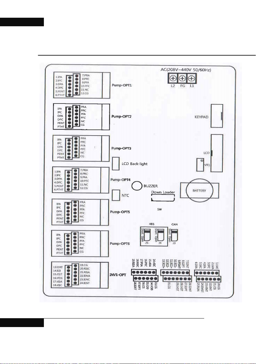
1.Control board arrangement and description.
52 BOOSTER PUMP SYSTEM
Page 53
BOOSTER PUMP SYSTEM N747D
1:
contact
contact
input terminal
RS485 signal earthing
common terminal
Inverter 0 initializing relay C
contact
Inverter 1 initializing relay A
contact
Inverter 1 operation relay A
Externally incoming signal
current(4~20mA)
voltage(0~10V)
Main Board
LMC Error lamp relay C contact 24: EMST System emergency operation signal terminal
2: LMA Error lamp relay A contact 25: RUN System start/stop signal terminal
3: SFC Sysetm error relay C contact 26: S1NT Pressure sensor1 (-) terminal
4: SFA Sysetm error relay A contact 27: S1PT Pressure sensor1 (+) terminal
5: SRC
6: SRA
7: S2NT Pressure sensor2 (-) terminal 30: CAN- CAN signal low terminal
8: S2PT Pressure sensor2 (+) terminal 31: CG CAN signal earthing common terminal
9: CG Earthing common termin al 32: CAN+ CAN signal high terminal
10: PSWT
11: 485- RS 485 sig nal Lo w te rm inal 34: VO0 inverter 0 frequeancy setup voltage(0~10V)
12: CG
13: 485+ RS485 signal High terminal 36: CG Earthing common termin al
14: RI0C
15: RI0A
16: PC Mulifunction relay C contact J1 CAN terminating resistence SW(used when short)
17: PA Mulifunction relay A contact J2 RS485 terminating resistence SW(used when short)
18: RI0C
19: RI0A
20: CG Earthing common termin al
21: CG Earthing common termin al (Vout: voltage, lout: current)
22: iINT
23: VINT
Sysetm operation Relay C
Sysetm operation Relay A
Emergency pressure siwtch
Inverter 0 operation relay C
contact
contact
Externally incoming signal
28: LV2T Low level sensor 2 input terminal
29: LV1T Low level sensor 1 input terminal
33: CG Earthing common terminal
35: iO0 inverter 0 frequeancy setup current(0~11V)
37: IOFT Inverter 0 error recognition terminal
38: IORT Inverter 1operation recognition terminal
Inverter 0 frequency setup: current/voltage adjusting SW
J3
(
Vout: voltage, lout: current)
Inverter 1 frequency setup: current/voltage adjusting SW
J4
VR1 LCD display setup
Battery TIME IC backup ba tt e r y
BOOSTER PUMP SYSTEM 53
Page 54
BOOSTER PUMP SYSTEM N747D
terminal
Pump option board
1: IPA Inverter pump relacy A contact 13: I1RT Inverter 1 opertation recognition terminal
2: IPC Inverter pump relacy C contact 14: i01 Inverter 1 frequency setup current(4~20mA)
3: DPA pump relay A contact 15: IENA Inverter 1 pump relay A contact
4: DPC pump relay C contact 16: IENC Inverter 2 pump relay C contact
5: PENT Pump recognition terminal 17: rI1A Inverter 2 initializing relay A contact
6: PTHT Pump overload terminal 18: rI2C Inverter 3 initializing relay C contact
7: PRA Pump operation relay A contact 19: CG Earthing common terminal
8: PRC Pump operation relay C contact 20: VO1 Inverter 1 frequency setup voltage(0~10V)
9: PFA Pump operation Error A contact 21: FI1T Inverter 1 error recognition terminal
10: PFC Pump operation Error C contact 22: RI1A Inverter 1 operation relay A contact
11: NC Not in use 23: RI1C Inverter 1 operation relay C contact
12: CG
Common terminal of input
Inverter option board
24: IENT Inverter 1 operation status recognition terminal
54 BOOSTER PUMP SYSTEM
Page 55

2. Check items
1. No operation is started when powered ON;
⑴ Check power voltage (208V~440V).
⑵ Check power, wire short and contact terminals.
2. When powered ON, only LCD Back Light is turned on;
⑴ Turn VR counterclockwise with PIN driver.
⑵ Check cables connected to LCD.
3. No front Key works;
⑴ Check cables connected to control board Key.
4. After set front panel switches for pump #1, Pump #2 and Pump #3
at AUTO position, no pump is not identified on the LCD screen;
⑴ Check switch contact points.
⑵ Verify the shortages of 5. PENT and 12. CG wire of Pump-OPT
board.
⑶ Check the contact point of 5. PENT and 12. CG wire of Pump-
OPT board.
(Verify LED ON state of Pump-OPT board.)
5. “Start/Stop” switch of the front panel does not work;
⑴ Check switch contact points.
⑵ Verify the shortages of 20.CG and 25. Run wire of main board.
⑶ Verify the contact points of 20.CG of main board and 25. Run
wire. (Verify LED ON state of main board.)
6. The output of inverter is not sufficient;
(EX. While front LCD shows 100%, internal inverter operates in
50Hz.)
⑴ Adjust DAC value in installer’s settings.
7. While the inverter is displayed on front LCD, pump does not work;
⑴ Check wire shortage and contact points of 18.RI0C and
19.RI0A of main boar d.
⑵ Verify if any short raises in 18. RI0C and 19. RI0A wire. ( RUN
signal work when short)
⑶ Verify the shortages and contact points of 35.VO0 and
36.CGwire.
⑷ Check DC voltage of 35. VO0 and 36. CG wire in main board.
(EX. DC 5V = 30Hz, DC10V = 60Hz)
BOOSTER PUMP SYSTEM 55
BOOSTER PUMP SYSTEM N747D
Page 56

BOOSTER PUMP SYSTEM N747D
8. MC does not work in each pump;.
⑴ Check if each MC power is 220 V.
⑵ Verify shortages and contact points of 1. IPA, 2. IPC, 3. DPA
and 4. DPC wire in Pump-OPT.
9. There is big gap between analog pressure gauge and the current
pressure of LCD screen;
⑴ Check the maximum pressure sensor value in use.
⑵ Adjust the maximum pressure sensor value in the installer’s
setting screen.
10. Analog pressure gauge is very close to the current pressure of
LCD screen;
⑴ Adjust sensor correction value in the installer’s setting screen.
11. Main pump and auxiliary pump operate continuously ;
⑴ Check the rotation direction of the pump ( it’s possible in test
operating).
⑵ Re-set the operating pressure and time of the auxiliary pump.
12. Auxiliary pump operates frequently;
⑴ In the user setting screen, re-set the operating pressure and
time of auxiliary, sequential stop pressure and time.
13. Only main pump operates.
⑴ In the user setting screen, re-set the shift time of main pump.
⑵ Shift the pump by operator with the front switch.
14. Frequent starting phenomenon happens in emergent operation
due to the inverter trouble;
⑴ In the user setting screen, re-set the sequential operation
pressure and time, sequential stop pressur e and time.
15. It is changed to “sequential operation 2” by user;
⑴ Adjust the deviation of pressure switch.
16. Various alarms raise (Buzzer, Lamp operates);
⑴ Enter front numeric Key and initial screen Key once. (Buzzer
OFF, Lamp OFF)
⑵ Check the caused troubles and take corrections.
56 BOOSTER PUMP SYSTEM
Page 57
17. Auto-operation is not available in low pressure alarming;
⑴ Set the pressure time of low pressure alarm more than 10
seconds, then stop the front panel “START/STOP” switch and re-start.
⑵ Set one of the front panel switch of pump 1, pump 2, pump 3
and pump 4 as MANU, so that one pump can be started and
increases the pressure up to the low alarm setting pressure.
18. Control of inverter is not available;
⑴ Check the inverter control method - voltage method, or current
control method;
⑵ If inverter control method is by current, check whether the J3
switch of main board is Iout direction. If the control method is by
voltage, it should be opposite direction ( Ex-factory default setting
is voltage control method).
3. Pump test operation
Thank you for your selection of our boost pump system.
In this section, check items, procedures and manuals for test
operation are summarized for our boost pump users.
The least items to be entered essentially for test operation
must be entered.
1. Check items before test operation
- Check site circumstance
1) Is water sufficient in water tank?
2) Is power connected?
3) Is the piping connection well?
2. Procedure of pump test operation
Before the site test operation, make sure to confirm below
items.
1) Has water been supplied to the site?
2) Is the wiring of panel and motor well connected.
3) Is the power supplied?
3. Manual for boost pump system test operation
1) Check if water is sufficient in the water tank.
2) Check if power cables of motor and panel are connected.
3) Open the water tank valve and inlet/outlet valves of pump.
BOOSTER PUMP SYSTEM N747D
BOOSTER PUMP SYSTEM 57
Page 58
BOOSTER PUMP SYSTEM N747D
4) Remove all air by opening air cocks of inlet and pump, until
water is dispensed only.
5) Close air cocks .
6) Turn on all internal NFB (breaker) of panel.
7) Turn on the power switch of the panel front.
8) If it is 3 pump system, then set switches of PUMP#1, PUMP#2
and PUMP#3 at AUTO position.
9) Press test operation Key on the controller ( the rotation
direction of the motor fan is counterclockwise). Press
once then direct-input operation starts, press twice then stops.
Again press
then stops. If the motor rotation direction is wrong, re-connect
of the direct-input starting in RST or RTS order. In case of
inverter starting, change the inv erter output termi nal fr om UVW
to UWV.
10) Once rotation direction is confirmed, then verify if the set
pressure of controller LCD screen is the desired input value ( in
case of change set pressure, correct the date · set pres sure
according to this manual printed inside of the panel).
11) When all steps are completed, set “START / STOP” switch at
“START” and start the operation.
Key once then inverter starts, press twice
Key
1. Emergency operation
Types of emergent operation
Emergent operation system is required against to any emergency
of water supply pump for its special requirement.
- In case of inverter failure, automatic emergent operation /
sequential 1 operation / sequential 2 operation
1. Automatic emergent operation in inverter failure
Reason : In case of inverter failure
Starting method :
If inverter is in failure, RPM of main pump is out of control.
Even in such situation, as water shall be supplied until A/S team
arrives, therefore, automatic emergent operation ( pressure method)
is carried out.
Its operating principle is ; pipe pressure can be detected by pressure
transmitter then normal operation is sustained by program control of
controller in all functions such as shift operation excluding RPM
control.
58 BOOSTER PUMP SYSTEM
Page 59

Set starting deviation pressure value becomes the condition of pump
starting when operation mode is switched to emergent automatic
operation. Setting of starting deviation pressure is available, however
its initial value is set as 0.5bar.
In this case, if set pressure is 4.0 bar, then sequential auxiliary pump
starts if it’s not above 3.5bar.
As the condition to stop is depend on the set value of auxiliary stop
deviation pressure, if auxiliary stop deviation value is 0.5bar, then it
shall be 4.5bar to stop the pump sequentially.
In this process, after all pumps stop and then if it’s 3.5bar or less
then it operates again.
The stating deviation pressure can be corrected through sequential
operation pressure and sequential stop pressure items of “User
setting [1]”. Please note that if the value is too small, the frequency of
starting/stop increases. Please call our A/S team to get support while
the pump operates under emergent automatic operation mode.
Indications :
In case of inverter failure, auto emergent operation is carried out
automatically and the failure notice is indicated in main screen. In the
bottom of present pressure of initial screen, the notice of “Inverter is
abnormal” is indicated, so please make sure to check it in daily
check.
2. sequential 1 operation
Reason : When replacing of abnormal inv erter
Starting method :
Star ting met hod is same as the principle of automatic emergent
operation in case of inverter failure. In “sequential 1 operation”,
emergent operation is carried out forcib ly as because w ater can be
supplied only by pump when inverter shall be replaced due to
inverter failure. sequential 1 o perati on can be carr i ed out through
“Installer’s setting”. “Inst al ler’s setting” is only for auth oriz ed
engineers, but not disclosed to general consumers due to the
possibilities including serious failure or accident by unauthorized
change of settings.
Caution : User’s setting mode shall be accessed only by authorized
engineers.
3. sequential 2 operation
Reason : In case inverter and pressure transmitter failed at the
same time.
Starting method:
BOOSTER PUMP SYSTEM 59
BOOSTER PUMP SYSTEM N747D
Page 60

BOOSTER PUMP SYSTEM N747D
Item
Specification
Operation of ON-OFF control method is carried on by Max/Min set
value of pressure switch. A s it is under cont rol of controller, gener al
functions such as shift operation can be carried out. Also water is
supplied continuously, however, the pipe pressure is little bit unstable
than RPM control due to the characteristics of ON/O FF of pr essur e
switch. Therefore, in case of sequential 2 operation, please call our
A/S team immediately to get support.
3. sequential 3 operation
Reason :
This is the last emergent operation method to be carried when
normal operation is unavailable due to the failure of most of core
components such as inverter, pressure tran smitt er, pressure sw itch,
controller and etc.
Starting method:
Minimal water can be supplied through operation with #1 pump only
by pressure switch, if the “operation select” switch of the panel is set
at emergency position manually. In this case, please call our A/S
team immediately to get support.
Occurrence frequency : It is very rare to operate by the emergency
switch.
5. RS-485
Communication specification
Com Speed 1200/2400/4800/9600/19200 bps
Control procedure Async communication
Communication system Half duplex system
Bit 8 bit
Stop bit 1 bit
Error Check(CRC16) 2 byte
Parity check None
60 BOOSTER PUMP SYSTEM
Page 61
Code
Name
READ
Single Write
Setting for communication
Communication Protocol
ModBus- RTU Protocol
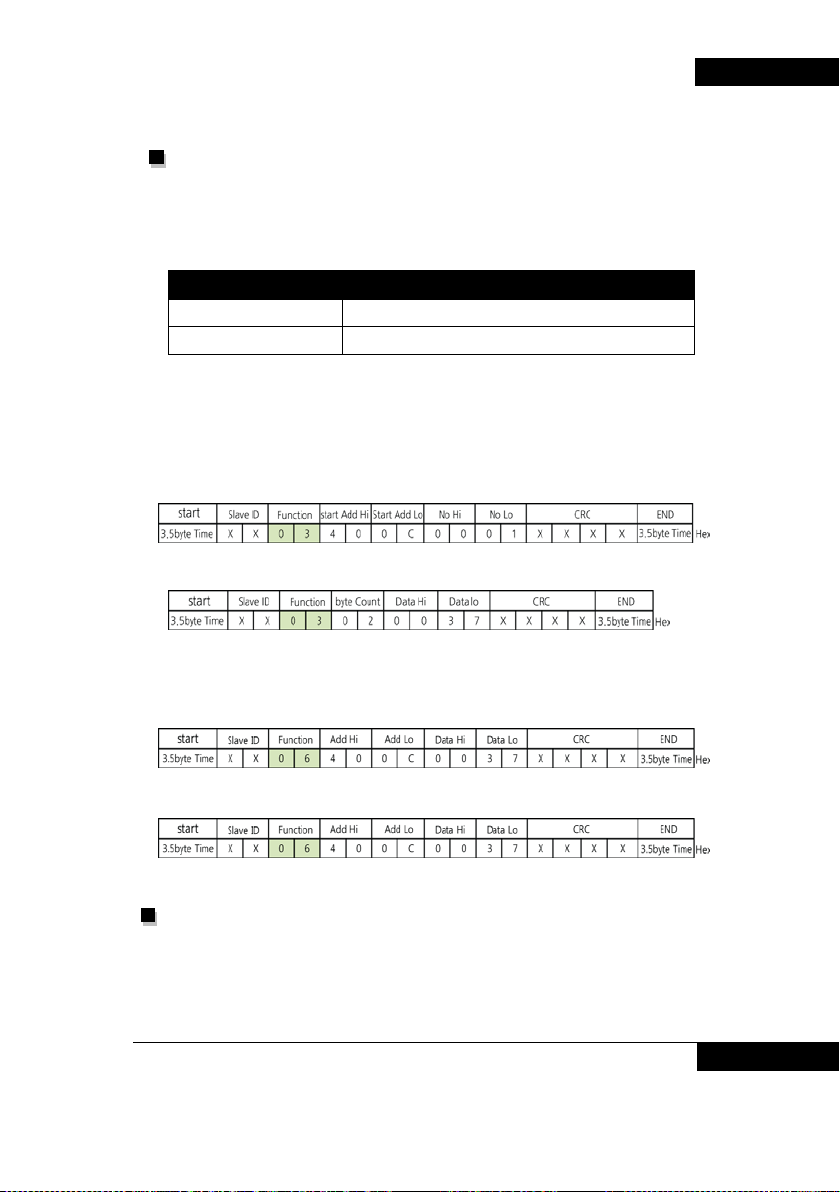
Function code
0x03 Read Hold Register
0x06 Preset Single Register
- Query (example)
- response
BOOSTER PUMP SYSTEM N747D
- Query (example - Pressure 5.5bar)
- response
Installer setting [3] (Refer Page 38 ~ Page 40 )
-RS-485
-Slave ID
BOOSTER PUMP SYSTEM 61
Page 62

BOOSTER PUMP SYSTEM N747D
Diagnosis
Check Points
Remark
Address
Parameter
Scale
Unit
R/W
내용
-BAUD RATE
-DELAY TIME
-DRIVE MODE
Refer Page 53
Main board
Check connection of N747D and equipment
Check whether RS485 is use or not Refer Page 38
Check communication Refer Page 38
Check N747D Slave ID
Check the start of master
11.485- 485 signal low
12.GND 485 Ground
13.485+ 485 signal high
Protocol Slave ID should be
Same with N747D Slave
(Refer Page 38 )
Installer program (Format)
Parameter ADDRESS
0x4000 Program version 0.01 R 0~65535
0x4001 Operation mode R 0 : Controller key 1: RS-485
0x4002 System operation R/W 0: Stop 1: RUN
62 BOOSTER PUMP SYSTEM
 Loading...