

Page 1
USER MANUAL
MODEL: XF124
COMMERCIAL FROZEN DRINK MACHINE
Page 2
SAFETY PRECAUTIONS
It is important to comply with all of the following safety precautions or severe personal injury or damage to the machine
may occur.
1. Prior to operating the machine, every operator must read and understand the operating instructions in this
manual. If any potential operator does not understand any instruction in this manual, they should not operate
the machine. Please call Donper USA’s tech support line for any questions on the content of this manual.
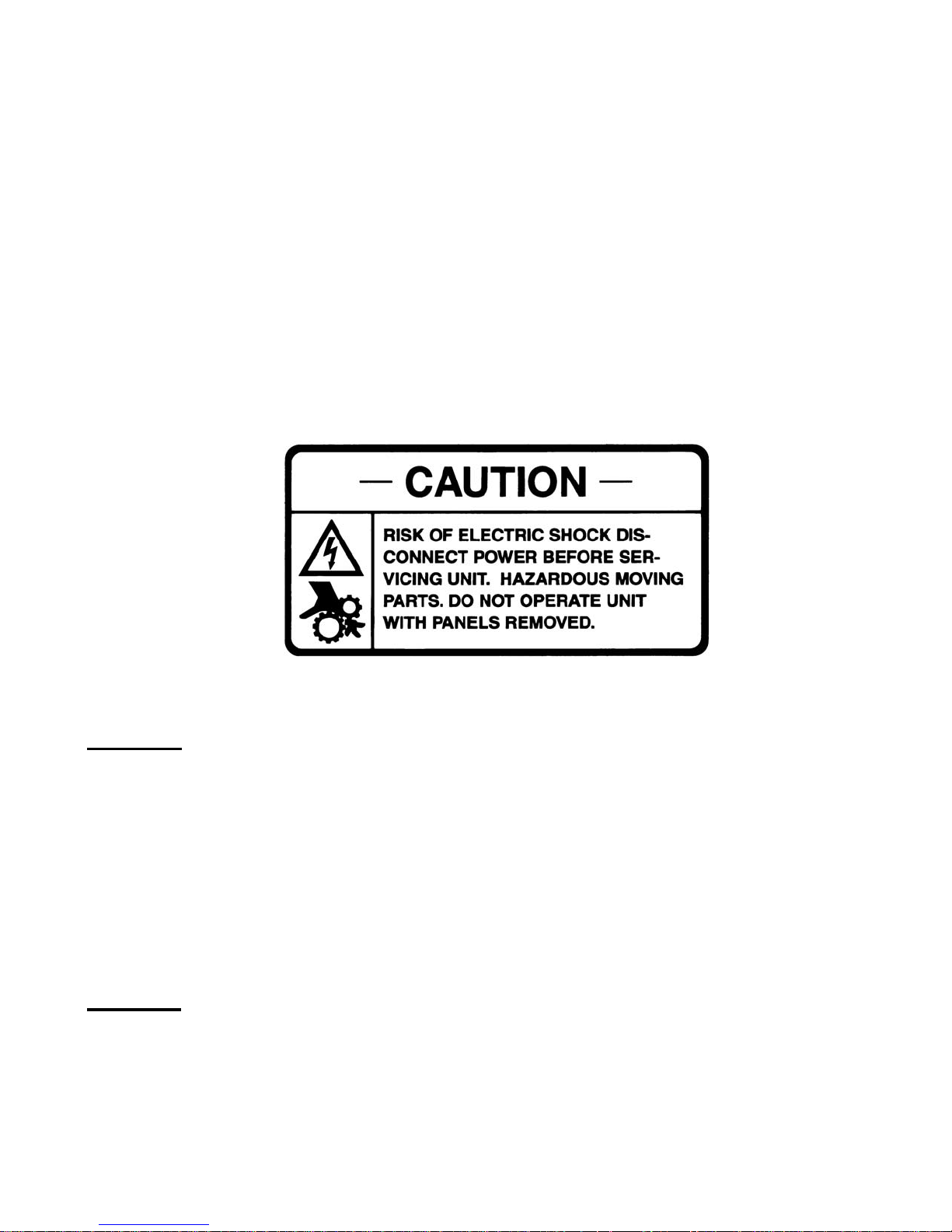
2. It is important to observe all warning labels on the machine. If any warning labels are missing or damaged, replace
them immediately.
3. Do not wear loose fitting garments or jewelry when operating or servicing the machine as these items may become
attached to m oving com pone nts of t he m achine a nd m a y cause seri ous bod il y injury.
4. Stay alert at all times during operation of the machine.
5. Keep operating area near the m ac hine cle an an d dr y to avoid ac c idents and possi ble b odil y injur y.
6. Do not attempt any repairs or service unt il the main power supply to the machine has been unplugged.
7. Do not put objects or fingers in the dispense valve aperture as serious bodily injury may occur.
8. Do not operate machine if any excessive noise or vibration occurs. Contact your authorized service agent when any
unusual noise or vibration begins and do not operate the machine until the service agent has repaired the machine.
9. Be certain the machine is installed with adequate space for proper air circul ation, as failure to provide sufficient
ventilation will reduce machine performance and void the machine warranty.
MACHINE APPLICATION AND SPECIFICATIONS
Model XF124
The machine consists of a freezing cylinder with a rotating internal auger or beater bar that is belt-driven by an electric
motor. The auger has p lastic sc raper blades that scrape frozen product off of the inside of the refrigerated cylinder
walls. The consistency or thickness control in the XF124 is a very reliable mechanical control system, whe reby a torque sensing
assembly on the drive motor determines when the cooling compressor should be turn ed off to maintain desired
product consistency. A self-closing dispensing valve is attached to the front of the freezing cylinder and this valve
assembl y is tr ansp ar ent to al lo w the us er t o vi ew th e pr od uct in the free zin g c ylin der . The unit has an adjustable consistency
control insid e the ri ght s ide panel of the m ac hine ( which sho uld not be adj uste d with the m ac hine on or plugg e d
in) and a mix low indicator light on the front of the m achine to alert the user when m ore mix should be add ed to the
hopper machine. The hop per of the machine is refrigerate d to precool the product before it g oes into the freezing
cylinder so that your freeze and recovery times will be shortened. When properly maintained and operated, the XF124
will provide many years of service. Proper care includes regular cleaning and maintenance. To minimize the amount
of maintenance necessary, follow the operat ing proc ed ures outlined in this manual.
Product Tips
The XF124 was designed to dispense a wide variety of frozen beverages including frozen margaritas, daiq uiris, fruit
juice, lemonade, slushes, and other frozen cocktails. These products can be served in consistencies ranging from thin
to fairly thick. A red spring is used on the drive motor to adjust product consistenc y to serve thin to medium products.
The yellow spring is used for thicker products. The spring is located next to the drive motor behind the right side panel.
Over an extended period of time, some products, such as frozen cocktails that contain alcohol, have a tendency to
separate or stratify in the machine hopper . Separation of product in the hopper can result in frozen product quality
inconsistency, so it is advised to stir the mix in the hopper occasionally to eliminate product separation.
Page 3
Dimensions
(H
26-1/2”H x 13”W x 29”D
Electrical
115V / 60Hz / 1 PH
Circuit NEMA #
5-15R
Drive Motor
1/2 hp,
Compressor
3/4 hp
Cooling
Air-cooled
Actual Weight
175 lbs (79.4 kg)
Mix Hopper Capacity
5 gallons (18.9 liters)
Freezing Cylinder Capacity
1-1/2 gallons (5.7 liters)
Refrigerant
R404a
Contact your local health department regarding its regulations for proper mix handling and storage.
Feed Tube
The XF124 uses a metering device, known as a feed tube, to feed a ratio of liquid mix and air into the freezing cylinder,
and to reduce the frozen product rising out of the freezing cylinder back into the hopper.
Product Mix
Freezing characteristics are affected by the amount of sweeteners, solids, and alcohol in the mix. The amount of
sweeteners and solids is called BRIX and can be measured with a refractometer. A BRIX reading of bet ween 11 and
16 will provide optimum machine operation. Mixes with this BRIX level will freeze down to a smooth, uniform
consistency. Mixes with a BRIX measurement above 16 m ay take longer to freeze and may be soft and/or wet in
consistency when dispensed. Mixes with a BRIX level below 11 may have larger ice crystals and may dispense slower
than usual. Alcohol content also affects product freezing characteristics, as a higher alcohol content lowers the freezing
temperature of the mix and may prevent the machine from cooling the mix to the temperature where the mix will be at
the proper thickness. For maximum output capacity, pre-chill mix before adding it to the machine. Pre-chilled mix
reduces the cooling s ystem workload and speeds the initial freeze time. It is normal for output capacity to decrease
when warm mix is added or when the machine is operated in a warm or humid location.
Machine Specifications
XF124
x W x D)
67 cm x 33 cm x 74 cm
Dedicated 15 Amp circuit
INSTALLATION
1. Place the XF124 on a level counter that is stable and strong enough to safely support the machine’s full weight with
mix in it (typically 250 lbs).
2. Make sure machine is to be placed in a location that is within 6’ of a properly grounded c ircuit and allows adequate
space (at least 6 inc hes) o n each of the lef t, right , an d b ack sides of the machine for proper air circulation.
NOTE: Failure to allow adequate ventilation will substantially reduce the machine’s performance, may
cause damage to the machine, and may void the warranty due to improper operation of the machine.
NOTE: Locating the unit in high ambient temperatures (over 90°F) will reduce the performance of the machine.
3. Reverse the position of t he dis pense va lve h andle . Dur ing shipm ent th e hand le is pos iti oned c lose to th e unit to
prevent damage. R emove the pin on the d ispens e v al ve and rotate the handle in the dispense valve half a t u rn.
This will position th e end of the handle awa y from the m achine abo ut 4 inches . Repl ace th e pin in the d ispens e
valve and the valve is ready for use.
4. Be sure ON-OFF-CLEAN switch (toggle switch located underneath the lighted sign on the left front side of the machine)
is in the “OFF” position.
5. Connect the power cord directly to a properly grounded 120V/60Hz, 20 Amp DEDICATED circuit. No other
equipment should be on the same circuit as the XF124.
Page 4
Page 4
Model 3311
Do not use an extension cord to power the XF124 or damage to th e machine m ay occur due to the voltage drop in the
extension cord.
DO NOT MODIFY THE POWER CORD OR PLUG IN ANY WAY OR SEVERE BODILY INJURY CAN OCCUR.
ONLY OPERATE THE MACHINE ON A 3 PRONG GROUNDED PLUG OR SERIOUS BODILY INJURY MAY OCCUR.
Running the XF124 on an inadequate power supply or otherwise not complying with the requirements of this section will
cause damage to the machine and will void the warran ty.
6. Pour liquid mix into the hopper.
7. Insert the feed tube in the hopper hole (if desired).
8. Turn the power switch to the ON position to begin freezing the mix.
OPERATION AND ADJUSTMENTS
How to Operate
1. Sanitize unit before use.
2. Fill the mix storage hopper and
3. Turn power switch to “ON” position.
4. Allow product to freeze in barrel. Compressor will turn off when product reaches pre-set consistency.
5. To dispense product pull down valve handle and release when done.
6. If product consistency is not as desired, adjust per the instructions herein.
7. Refill mix storage hopper when “mix out” light is ON.
8. Clean the unit regularly following local health codes.
9. Perform maintenance when necessary to increase the life of the unit. See the chart in this manual for regular
maintenance schedule.
Mix Low Function
1. The XF124 senses when mix is low in hopper. When the mix level in the hopper is low, the RED mix low light
located in the front of the machine next to the valve block will illuminate red.
NOTE: Do not run the unit under mix low conditions for long periods of time. This can affect machine performance or
damage components of the machine.
Consistency Adjustment
From time to time, it may become necessary to readjust the consistency or thickness of the XF124 to
compensate for variation between different mixes or to switch from one type of product to another. This
adjustment is made as follows:
1.
Disconnect electrical power to the machine
WARNING: Do not attempt to adjust the machine until electrical power has been
disconnected.
2. Remove right side panel (facing the front of the machine, the right side panel)
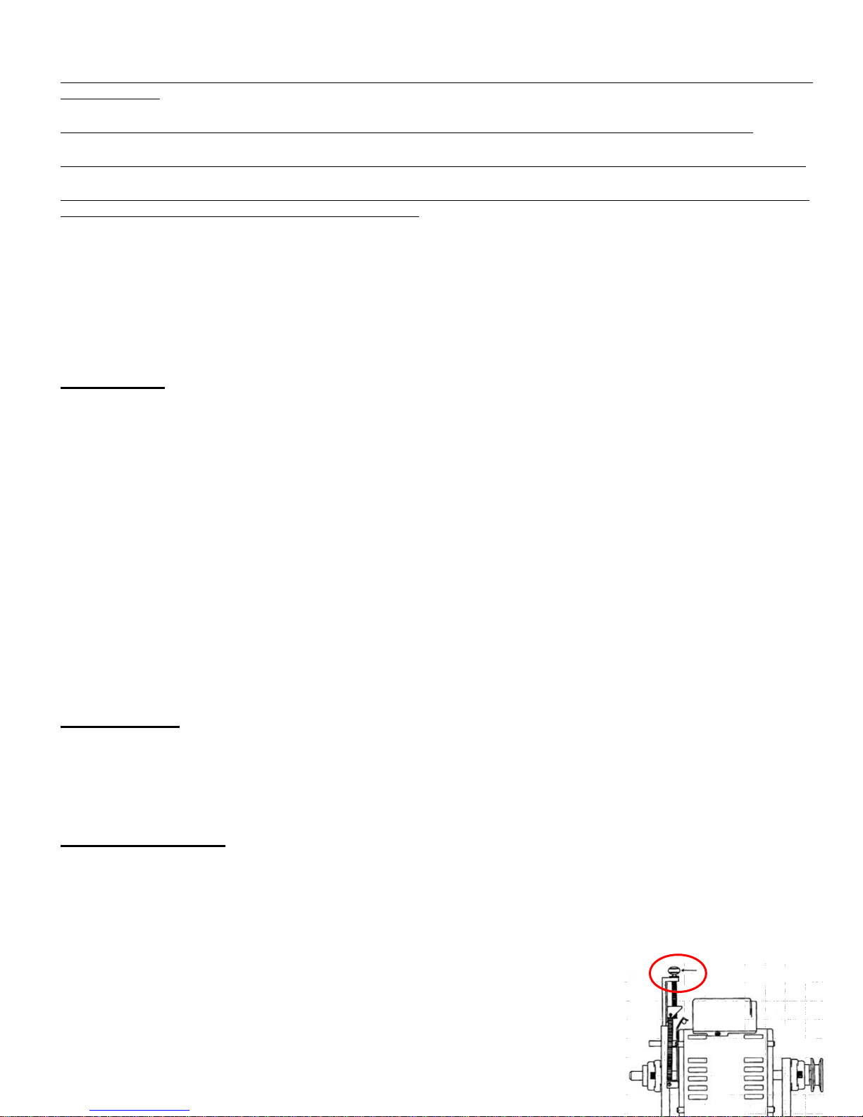
3. Use the adjustment screw, situated on the front of the drive motor mounting bracket
.
Page 5

to change product thickness. Turn the thumbscrew (3 full turns for red spring, 1 turn for
yellow spring) to make a noticeable change in consistency.
NOTE: Clockwise (when look ing do wn at the t op of the adjustm ent s cre w) is for thicker product consistency
and counter clockwise is for thinner product consistency.
4. Reinstall the side panel, reconnect power.
5. Turn machine to “ON” and allow it to freeze to desired consistency.
6. Check product. Repeat process until desired consistency is achieved.
NOTE: When making changes to a thicker setting, recheck consistency again after the compressor has stopped
cooling and has cycled off. When adjusting (counter-clockwise) to a thinner consistency, a large portion of product
must be drawn from the dispense valve to reduce the product thickness below the new set point, a nd then allow the
machine to refreeze product to the new setting, which may again be checked once the compressor has stopped
cooling and the machine has cycled off.
CARE AND CLEANING
Cleaning and sanitizing frequency must be followed according to state and local health department regulations.
NOTE: Each time the machine is fully disassembled, all food zone machine components (all p arts of the mac hine
that come in contact with the product being dispensed) must be thoroughly washed and sanitized using procedures
recommended by the local health department. In lieu of local health department recommendations, use a three
compartment sink; one compartment to wash parts in detergent, one compartment to rinse, and one to sanitize.
Drain and Rinse
1. If the machine is empty, proceed to the Disassembly and Cleaning section below. If there is product in the
machine, turn the front panel switch to “CLEAN” and drain the remaining mix from the machine by dispensing the
product into a bucket from the dispensing nozzle.
2. Close the dispensing valve and turn machine to “OFF”.
3. Remove the feed tube and pour water into the storage hopper. Allow the water to fill the freezing cylinder.
4. Turn the panel switch to “CLEAN” for 5 minutes.
5. Open the dispensing valve and drain the water from the machine.
6. Turn the machine “OFF”.
7. Repeat steps 3-5 until the water drained from the machine is clear.
Disassembly and Cleaning
1. Disassemble the dispensing valve assembly.
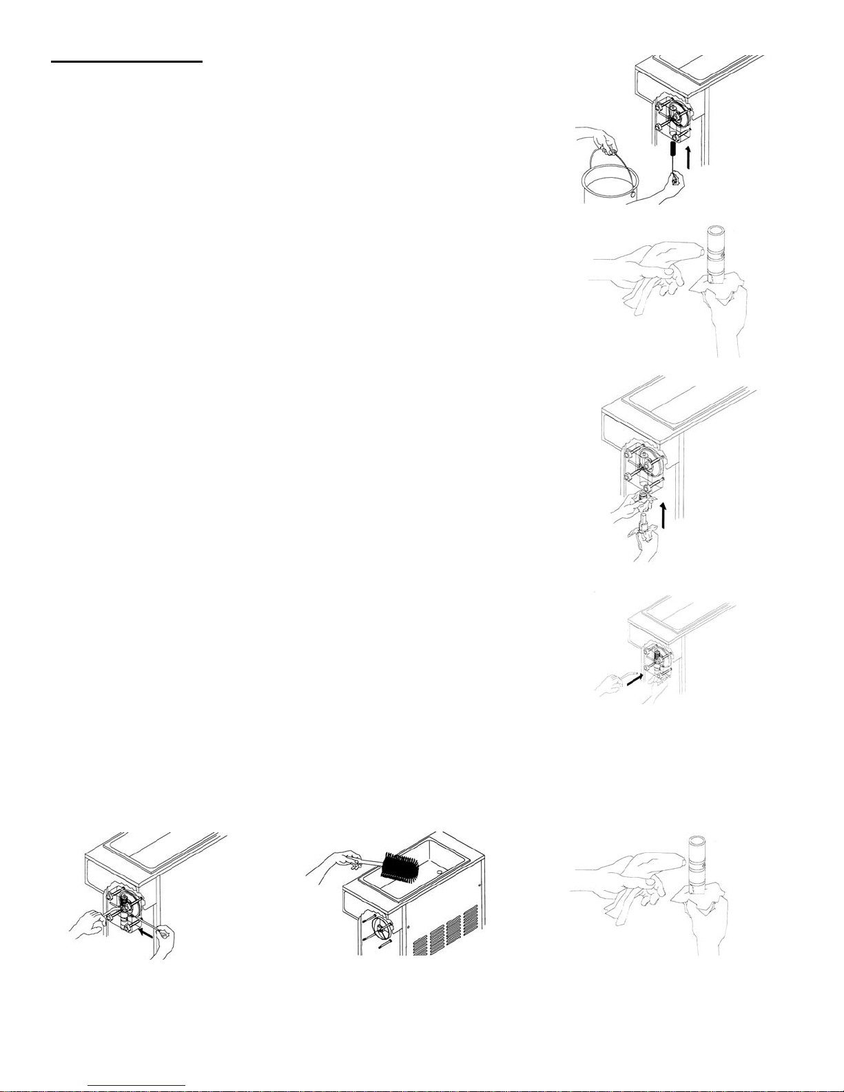
a. Pull out valve handle retaining pin while supporting the valve plunger from the bottom. Picture
b. Push up on the valve plunger and remove the stainless handle. Picture
c. Slide the valve plunger and spring downward to remove. Picture
2. Remove knobs and carefully remove the front dispensing valve assembly, leaving the beater bar assembly in
the cylinder.
3. Remove the o-rings from the plunger assembly and back of the dispensing valve body.
NOTE: To remove an o-ring first wipe off all of the lubricant using a clean paper towel. Pinch the o-ring upward with a
dry paper towel between your index finger and thumb. When a loop is formed in the o-ring, roll it out of the groove
with your other thumb. Always remove the o-ring farthest from the end of the plunger first. Carefully inspect t he orings and replace if necessary.
4. Remove the beater bar assembly from inside the freezing cylinder taking care to avoid damaging the rear seal
assembly at the back of the freezing cylinder. Disassemble the beater bar assembly by removing the stator rod
and front and rear stator rod bearings.
5. Slide the shaft seal off the beater bar shaft and inspect for damage.
6. Remove feed tube from bottom of hopper and remove o-rings.
7. Remove drip tray and empty contents.
8. Take all components to the cleaning area.
Page 6

Page 6
Model 3311
9. Prepare 1 gallon solution of hot tap water and a good grade of dishwashing detergent.
10. Thoroughly wash all components in a warm, mild detergent solution including the inside of the freezing
cylinder and the mix storage hopper. DO NOT WASH COMPONENTS IN A DISHWASHER.
11. Use a medium sized brush to clean the bottom of the valve body and the inside of the plunger bore with mild
detergent solution taking care to remove only remaining lubricant.
12. The exterior of the machine should be cleaned as needed with a mild food safe cleaner and cloth. Do not use
abrasive cleaners, such as cleansers or steel wool to clean the machine or damage may occur.
Reassembly
NOTE: Allow all parts to dry completely before reassembly.
1. Reassemble drip tray and re-install on front of unit.
2. Wet the inner rubber lip of the rotary half of the seal and the back end of
the beater bar shaft with water. Slide rotary half of assembly onto the b eater bar shaft, RUBBER FIRST, with the
smooth sealing surface facing the back of the beater bar. (S ee Figure U). Be sure the rotary half is fully seated
against the shoulder of
the shaft.
3. Insert the stationary half of the seal into the ribbed rubber boot with the polished surface facing out
(forward).
4. Lightly lubricate the ribbed rubber boot of the stationary ceramic seal (taking care not to get any lubricant on the
polished surface) and insert it straight back into the recess at the back of the freezing cylinder, RUBBER FIRST.
(See Figure V)
NOTE: The stationary half of the seal must be completely dry before reassembling. If the circular half of the seal is
white, make sure that the grooved side is toward the rubber. If the circular half is black, be sure the glossy side is
facing out.
5. Reassemble the beat er bar assembly, as shown in Figure W. Insert the larger front and smaller rear white
plastic bearings into beater bar, then slip in the stator rod.
6. Carefully and slowly guide the beater bar into the freezing cylinder, taking care not to damage the
seal assembly. Turn beater bar shaft until it engages the s quar e dri ve coupling. Slide the beater bar back
into the cylinder so that the two smooth sealing surfaces meet. (See Figure X)
7. Inspect and lightly lubricate the large square o-ring and refit it into the back of
the valve block assembly. Install the valve assembly on the front studs and
tighten the knobs until they are finger tight. Do not use tools to tighten
knobs.
NOTE: Failure to lightly lubricate the large o-ring can result in product leakage.
Page 7
Sanitizing and Refilling
1. Reassemble feeduretor by installing the two o-rings at the bottom of the feed tube.
2. Place the feeduretor assembly in the bottom of the hopper.
3. Install the o-rings on valve plunger and lay plunger assembly on a clean piece
of paper towel.
4. Prepare a minimum of 2.5 gallons (9.5 liters) of sanitizing solution (Kay-5
Sanitizer/Cleaner or equivalent) following the manufacturer’s instructions.
NOTE: Add 1 ounce of Kay-5 to 2.5 gallons (9.5 liters) of 120°F (50°C) water to
achieve a concentration of 100 parts per million.
5. Dip a medium sized brush into the sanitizing solution and sanitize the inside bore
of the dispensing valve. (Figure Y)
6. Place a small amount of lubricant onto a piece of clean paper toweling. Use a clean
piece of paper toweling to pick up the small end of the valve plunger assembly.
Apply a thin film of lubricant from the other piece of paper toweling. (Figure Z)
7. Slide the valve plunger spring over the small end of the valve plunger and, using
another clean piece of paper toweling, pick up the valve plunger at the outlet end
and insert plunger and spring into the valve body. (Figure AA)
8. Push up on the valve plunger and insert the stainless steel handle. (Figure BB)
9. Holding the handle down slightly so that the hole in the handle and valve block are
aligned, insert the dispensing valve handle retaining pin. (Figure CC)
10. Pour sanitizing solution into the mix storage hopper and allow the solution to fill
freezing cylinder. Use a large brush to sanitize all hopper surfaces. (Figure DD)
11. Turn panel switch to “CLEAN” and allow machine to run for 5 minutes.
12. Open dispensing valve and drain solution. Allow the beater bar to push
remaining sanitizer out of the freezing cylinder. Once the sanitizing solution is
drained, turn panel switch to “OFF”.
13. Place a small amount of sanitary lubricant onto another piece of clean paper
toweling. Use a clean piece of paper toweling to pick up the large end
of the feeduretor from the bottom of the hopper taking care not to touch the
sanitized feeduretor with your bare hand (Figure EE). Apply the lubricant on the
other piece of paper toweling to the two o-rings on the bottom of the feeduretor
assembly (Figure EE).
14. Place the lubricated feeduretor assembly on a clean piece of paper
Figure AA Installing Plunger and Spring
toweling.
15. Prepare fresh product according to manufacturer’s instructions.
16. Hold open the dispensing valve and pour product (approx. 10 oz.) into the
Figure Y Sanitize Valve Body
Figure Z Lubricate Plunger
hopper to allow this product to chase out any remaining sanitizer. Watch the
product flowing out of the dispensing valve and close the valve when the new
mix has purged the sanitizer remaining in the cylinder.
17. Use a clean piece of paper toweling to insert the sanitized feeduretor assembly
into the inlet hole in the hopper.
Figure BB Insert Valve Handle
18. Fill mix storage hopper with fresh product. Cover hopper with hopper lid.
19. Turn front panel switch to “ON”. Allow the machine to reach proper consistency.
Figure CC Insert Retaining Pin Figure DD Sanitize Hopper Figure EE Lubricate Feed Tube
Page 8
Model 3311
Page 11
&
Clean-In-Place Procedure (Daily Cleaning)
Part
Every 3
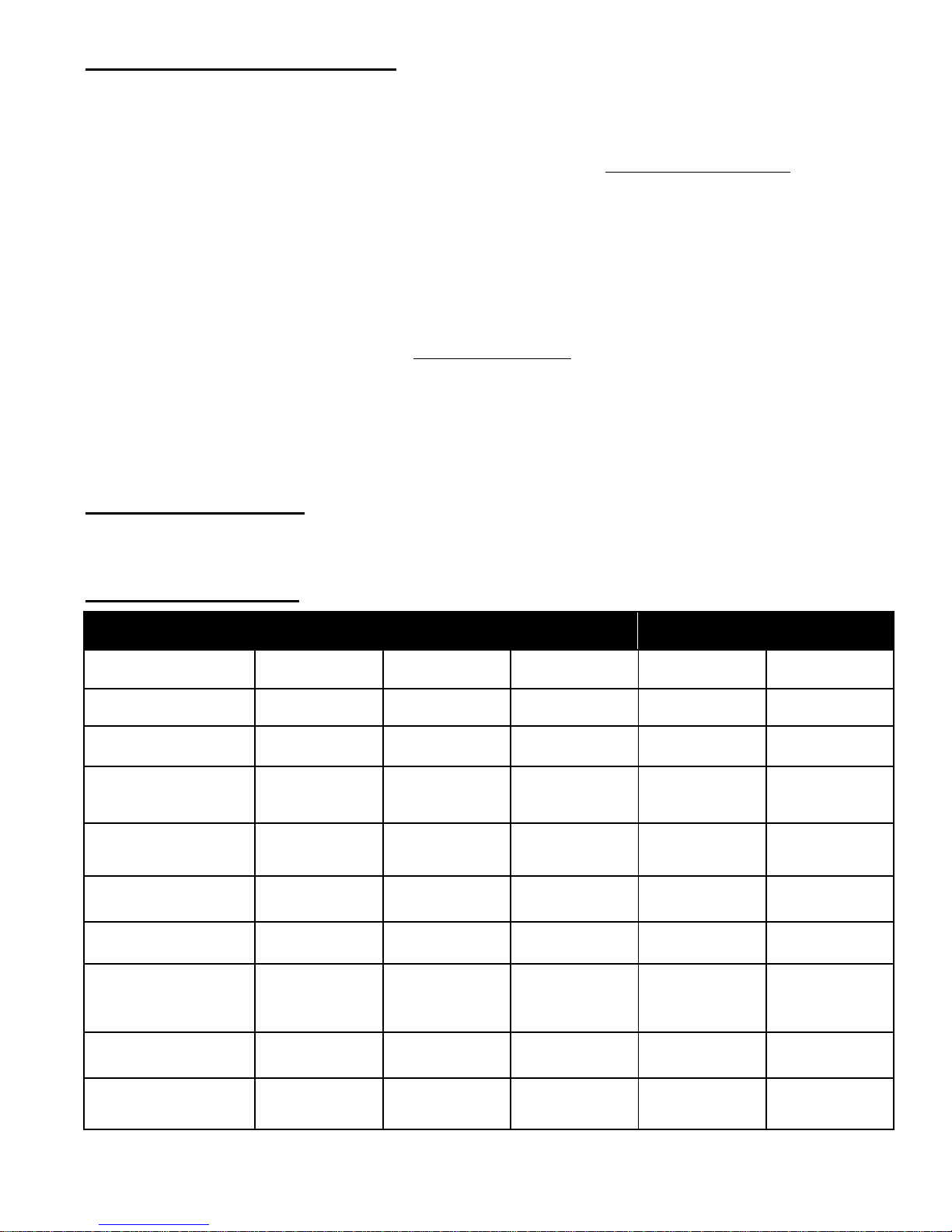
Every 6
Quantities to
Shaft Seal
Drive Shaft
Inspect & replace if
Drive Belts
Inspect & replace if
Scraper blades on beater
Square cut o-ring on valve
if
Thick Product
Plunger: 3
Inspect & clean
(Air-cooled units only)
This equipment has been approved for a Clean-In-Place procedure that does not require complete disassembly on a
daily basis. The unit still requires regular complete disassembly for cleaning and sanitizing. To perform the C-I-P
procedure follow the instruction below:
1. Empty any product in the machine and turn to OFF.
2. Disassemble the dispensing valve assembly following the instructions in Disassembly and Cleaning.
NOTE: Leave the valve block in place. Only disassemble the plunger, handle, spring, o-rings and pin.
3. Remove feeduretor assembly from hopper and remove o-rings.
4. Take all components to the cleaning area.
5. Carefully inspect the o-rings for cracks, chips or cuts and replace if necessary.
6. Prepare 1 gallon solution of hot tap water and a good grade of dishwashing detergent.
7. Thoroughly wash all parts including handle, pin, valve plunger, spring, feeduretor assembly and all o-rings in
detergent solution.
8. Use a medium sized brush to clean the bottom of the valve body and the inside of the plunger bore with detergent
solution taking care to remove any remaining lubricant.
9. Reassemble following the instructions under Sanitizing and Refilling.
NOTE: Run the unit with sanitizer on “CLEAN” for 20 minutes before draining and refilling.
MAINTENANCE
WARNING: Disconnect power for maintenance. Do not attempt to perform maintenance on the
Suggested Daily Maintenance
1. Clean, lubricate and sanitize the machine following guidelines.
2. Clean the exterior of the machine using a soft wet cloth. (Wipe down spinner if attached)
3. Empty drip tray.
Parts Replacement Schedule
machine until electrical power has been disconnected.
Description
Monthly
Months
Months
Annually
be Replaced
(W0340201 or W0340210)
(W0451067)
(W0450209)
bar
(if equipped)
body/face plate
(W0340055)
Front stator flange bearing
(W0430032)
Rear stator flange bearing
(W0430024)
Dispense valve o-rings
(W0340022)
Feed tube o-rings
(W0340011)
Condenser
if necessary
Replace
Replace
Replace
Replace
necessary
necessary
Inspect & replace
necessary
Replace
Replace
1
1
1
2
1
1
1
Plunger: 2
Standard Product
2 or 3
1
Refer to the Crathco Parts Price List when ordering the above parts
Page 9

Page 12
Model 3311
Preventative Maintenance Procedure (Every 6 to 12 Months)
A preventative maintenance visit should be performed every 6 to 12 months depending on the usage and environment where the unit is placed. (Ex. seasonal machines - once before season, year round machines - twice per year).
The following procedures should be performed during a preventative maintenance visit. This does not take the place
of daily care and cleaning procedures as described by local health codes and the manual. PM kit #W0890157 contains the standard replacement parts needed for preventative maintenance including o-rings, standard seal kit stator
bearings and drive belt. Units with a coconut oil product seal should order all parts separately. Units with scraper
blade beater bar will require the scraper blades be ordered separately.
• Verify ventilation is adequate (Air-cooled units: 6” minimum on both sides, open at top, and as far as possible from
dust sources; Water-cooled units: 0” on both sides, 3 - 6” at rear of unit and open at top).
• Verify adequate water flow and drain connections on water-cooled versions.
• Check product temperature and consistency for proper setting (refer to product manufacturer’s recommendation) adjust if necessary. Where equipped be sure to check the temperature in both the hopper and cylinder.
• Ensure product is being mixed properly and is within specification (check brix - most products should be around
13% - refer to product manufacturer’s recommendations for exact recommended brix).
• Check for any leaks.
• Empt y product from the unit. Disassemble unit completely (as if for cleaning).
• Clean and sanitize all disassembled parts following the cleaning instructions in the manual.
• Clean and sanitize hopper, freezing cylinder and splash zones on the machine.
• Check condition of all panels and lids - replace if necessary.
• Check beater bar scraper blades for wear if equipped - replace once per year minimum.
• Check beater bar for signs of wear - replace if necessary. Verify alignment when replacing.
• Check valve body gasket for wear - replace once per year minimum.
• Check valve body knobs (used to hold valve body in place) - replace if necessary.
• Check condition of shaft seals and stator bearings - replace once per year minimum.
• Inspect drip cup at back end of freezing cylinder for signs of seal leakage.
• Replace o-rings on hopper float (where necessary), dispense valves and feed tubes (lubricate).
• Lubricate parts where appropriate (dispense valve o-rings, feed tube o-rings, rubber boot of stationary shaft seal).
• Re-assemble unit and sanitize hopper and freezing cylinder by running CLEAN cycle.
• Clean and sanitize spinner if equipped.
• Check operation of merchandiser and mode lights - replace light bulbs if necessary.
• Clean reusable filter if equipped. Check condition of filter and replace if necessary.
• Clean condenser.
• Inspect the drive shaft and motor shaft bearings for excessive wear (drive shaft hole rounding out) - replace if
necessary. Verify alignment when replacing.
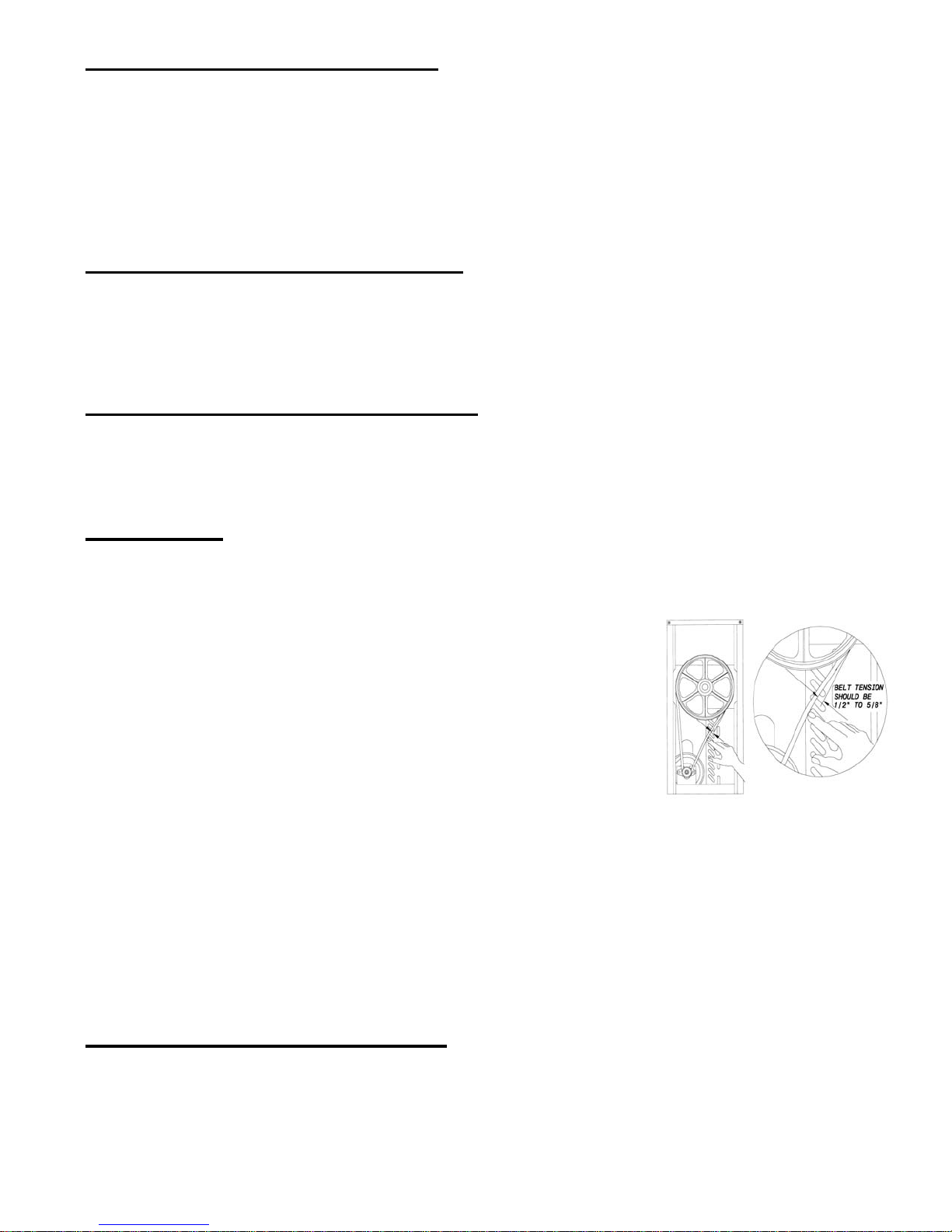
• Check V-belt tension (should be 1/2” - 5/8”) and verify all set screws are tightened - adjust if out of range. Replace
belt once per year minimum.
• Verify compressor operation and machine controller operation.
• Check electrical connections (outlet should be properly grounded with amperage capacity equal to or over the
amperage specified on the serial tag).
• Check fan operation (condenser fan) and clean fan blades if necessary.
• Review proper periodic care and cleaning instructions (disassembly, cleaning, sanitizing, lubrication, and
re-assembly) with store personnel. Train store personnel to follow proper procedures (stress importance of store
level maintenance ie. lubrication, filter cleaning, etc.).
• Make sure store personnel have appropriate supplies (lubricant, cleaning brushes and sanitizer) to care for
machine.
Page 10
Model 3311
Page 13
&
How to Clean Condenser (Air-Cooled Unit Only)
NOTE: Loss of refrigeration efficiency will result if condenser is allowed to become dirty. Excessive compressor run
time or loss of capacity are a good indication that the condenser needs to be cleaned.
1. Disconnect electrical power.
2. Remove side panels.
3. Place a damp towel over the side of the condenser opposite the fan motor.
4. Use compressed air or CO
use a condenser brush and vacuum cleaner.
2 blow out dirt from the fan side of the condenser. An alternate cleaning method is to
&
How to Clean Exposed Filter (Air-Cooled Unit Only)
1. Slide exposed filter out of the rails by pulling forward on the filter. It is recommended to remove the filter by using
2. Clean filter with liquid soap and water.
3. Soak filter for 15 minutes.
4. Rinse filter with heavy stream of water, opposite the direction of air flow. Allow filter to dry.
5. Slide the filter into the rails until the filter contacts the stop on the top rail.
How to Clean Concealed Filter (Air-Cooled Unit Only)
1. For concealed filters lift lid and pull up on filter tab to remove filter.
2. Clean filter with liquid soap and water.
3. Soak filter for 15 minutes.
4. Rinse filter with heavy stream of water, opposite the direction of air flow. Allow filter to dry.
5. Slide filter into top of filter cover with removal clip up and the air flow arrows facing the existing panel.
How to Adjust Belt
CAUTION: Procedure can create a loud noise.
the palm of your hand and applying even pressure to the face of the filter.
CAUTION: Unplug the machine before performing any adjustments. This procedure must be done by
Check the belt tension. The proper belt deflection is 1/2” over all. If the deflection
is more than 1/2” the motor will need to be lowered. If the deflection is less than
1/2”, the motor will need to be raised. Follow this procedure to adjust the motor to
achieve proper belt tension. (See Figure FF)
1. Unplug the machine and remove both side and rear panels.
2. Locate the motor flange bearings. These are the side mounted bearings that
3. Loosen the allen bolts on each bearing. Do not loosen the setscrews that hold
4. Lower the motor or raise the motor as needed. The motor must be kept level
from front to back. Do not lower or
5. Tighten all four allen bolts down. Align the motor pulley with the top pulley if needed.
6. The motor pulley should be in alignment with the large (driven) top pulley. Use a straight edge along the
7. If the pulleys are not in alignment, loosen the setscrew on the motor pulley and move either in or out as needed.
8. Tighten the setscrew back down on the motor shaft (use of non-permanent loc-tite is recommended). Please be
9. Return the unit back to service.
How to Change Back Lit Sign Merchandiser Bulb
1. Remove the two screws located on the top of either side of the sign.
2. Lower the metal enclosure that frames the merchandiser insert.
3. Pull merchandiser enclosure down and out.
4. Replace bulb inside by pulling bulb straight out of the socket. Firmly insert the new bulb into the socket.
5. Reassemble. For ease of assembly, put merchandiser and plastic lenses in light box before placing metal
a qualified technician.
hold the motor to the cradle. The motor is double shafted and the shaft
extends through a bearing on each end. The bearing is held to the motor
cradle by two allen bolts on each bearing.
the bearing collar to the motor shaft.
raise only one end of the motor. This will result in excessive belt wear and belt noise.
top pulley.
sure the setscrew is tightened down on the flat surface of the motor shaft.
enclosure back on.
Figure FF
Page 11

Page 14
Model 3311
GENERAL TROUBLESHOOTING
PROBLEM
PROBABLE CAUSE
REMEDY
Machine will not run or freeze down
• Machine not plugged in
• Plug machine in
Product too soft
• Consistency setting too loose
• Readjust consistency control
Product too stiff
• Consistency adjuster set too firm
• Readjust consistency setting or change
Product will not dispense
• Power switch OFF
• Turn power switch ON
Leakage from drain tube, front of
• Worn or defective shaft seal
• Replace seal and then lubricate at
Excessive Dispensing Valve Leaks
• Worn or defective o-ring(s)
• Replace and lubricate
Clicking sound from inside machine
• Low voltage
• Use dedicated circuit with proper
Thumping sound from inside machine
• Worn belt
• Replace belt
Scraping sound during freeze down
• Frozen product scraping off of
• Sound should go away when product
Premature seal wear
• Incorrect installation of beater bar
• Advise careful installation
Merchandiser light flickers when
• Low voltage
• Connect machine to dedicated
Machine problems originate from three sources - improper operation, mix problems or mechanical malfunction.
Always check for improper operation and mix problems first, as they are the most common cause of most equipment
problems.
&
Only a
CAUTION: Always disconnect power before attempting any maintenance procedures.
qualified
service
technician
should perform
• Circuit breaker tripped or fuse blown
• Machine in CLEAN or OFF position
• Obstructed condenser air flow
(Air-cooled units)
• Compressor not operating
• Beater bar not installed
• Low refrigerant charge
• Consistency setting at maximum
(red spring)
• Product BRIX level too high
• Too much alcohol in mix
electrical
and
• Product BRIX level too low
• Inadequate mix in hopper. Red MIX
LOW light on
• Consistency adjuster set too firm
• Feeduretor inlet hole clogged
• Drive belt broken or off pulley
• Drive shaft worn
• Drive motor failure
mechanical adjustments
• Reset breaker or replace fuse
• Switch to ON position
• Clean condenser. Allow 6” (15 cm)
on both sides
• Check for cause and correct
• Install beater bar (auger)
• Check for leaks, repair and recharge
• Change to yellow consistency spring
• Lower liquid product BRIX level
• Lower alcohol content
to red spring
• Increase product BRIX level
• Refill hopper
• Readjust consistency setting
• Unclog feeduretor inlet hole
• Repair or replace
• Inspect square drive shaft pocket for
excessive wear, replace
• Replace motor
or
repairs.
machine above drip tray
machine cycles
If you still need help, call our Service Department at (800) 695-4500 (Monday through Friday 8am - 8pm EST) o r an authorized service
center in your area. Please have the model and serial number ready so that accurate information may be given. Prior authorization
must be obtained from Grindmaster’s Technical Services Department for all warranty claims.
• Seal installed incorrectly
• Extension cord is used
cylinder walls
• No product in machine
• Improper drive shaft clearance
• Incorrect shaft alignment
each cleaning
• Remove and install seal
rating
• Connect directly to power source or
use power cord of proper size
is frozen to proper consistency
• Fill with product
• Adjust to proper
• Align shaft
circuit with proper rating
Page 12
Model 3311
Page 15
CHECK LIST
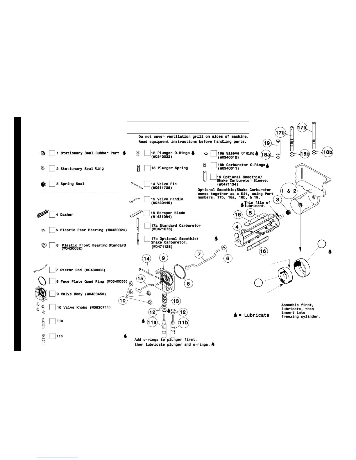
PARTS IDENTIFICATION
(W0631230)
Coconut Oil Seal (W0340210) and Standard Seal
(W0340201) include 1,2, & 3.
(W0430026)
Scraper Blade Beater bar
(W0430089)
Use with scraper blade beater bar
1
Rough Side
of Ceramic
2
Smooth
Shiney
Side
Slush Plunger (W0480438)
Thick Product Plunger
(W0480451)
Page 13
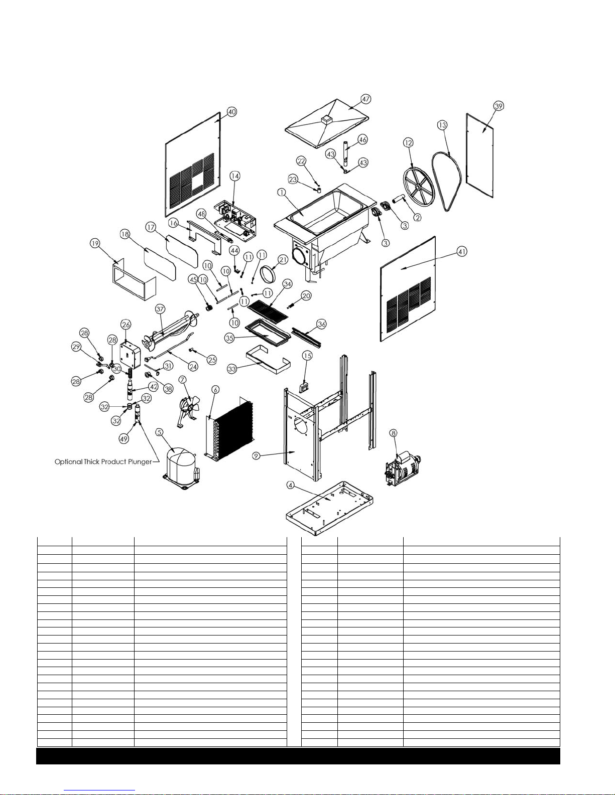
Exploded View
XF124
115V Air-Cooled Model
ITEM PART NO. DESCRIPTION ITEM NO. PART NO. DESCRIPTION
1 W0201272 Cylinder Assembly 26 W0480450 Valve Body
2 W0451067 Driveshaft, Slush 27 W0340055 Valve Square Cut O-Ring
3 W0380025 Bearing, 1” Bore 28 W0630711 Valve Knob
4 W0210106 Base Pan Assembly 29 W0480445 Valve Handle
5 W0200123 Compressor, #AKA171AT032A4, 115V, 3PH, 60HZ 30 W0631230 Valve Spring
6 W0200256 Condenser Coil, Air, CFB 31 W0611728 FasPin, Valve
7 W0321029 Fan Assembly 32 W0340022 Plunger O-Rings
8 W0321026 Drive Motor Assembly 33 W0472062 Pan, Drip Form X-LG
9 W0210083 Frame Assembly 34 W0472063-2 Insert, Drip Pan X-LG
10 W0110013 Valve Studs 35 W0631632 Drip Tray
11 W0611085 Nut, 5/18-18 S.S. Hex Nut 36 W0472064 Drip Pan Bracket
12 W0450053 Pulley, 10” 37 W0430026 Beater bar, Standard
13 W0450209 Belt, V 38 W0430032 Stator Flange Bearing
14 W0572202 Electrical Box Assembly 39 W0520063 Rear Machine Panel
15 W0570045 Ballast 40 W0520107 Left Side Panel
16 W0572290 Light Reflector 41 W0520065 Right Side Panel
17 W0631610 Front Display Lens 42 W0480438 Slush Plunger, Standard
18 W0631614 Acrylic Lens 43 W0340011 O-Ring, -115 Buna-N Feed Tube
19 W0572452 Electrical Box Cover 44 W0570018 Light, Indicator LT Red 12V
20 W0211112 Drain Tube Fitting 45 W0340201 Shaft Seal Set
21 W0340058 Barrell Gasket 46 W0471075 Feed Tube, Slush/Cocktail
22 W0340007 #108 Float O-Ring 47 W0520094 Hopper Cover
23 W0570941 Mix Low Indicator Float 48 W0570043 Bulb Fluorescent
24 W0430029 Stator Rod 49 W0480451 Thick Product Plunger
25 W0430024 Rear Stator Bearing
Page 16 XF124
Page 14
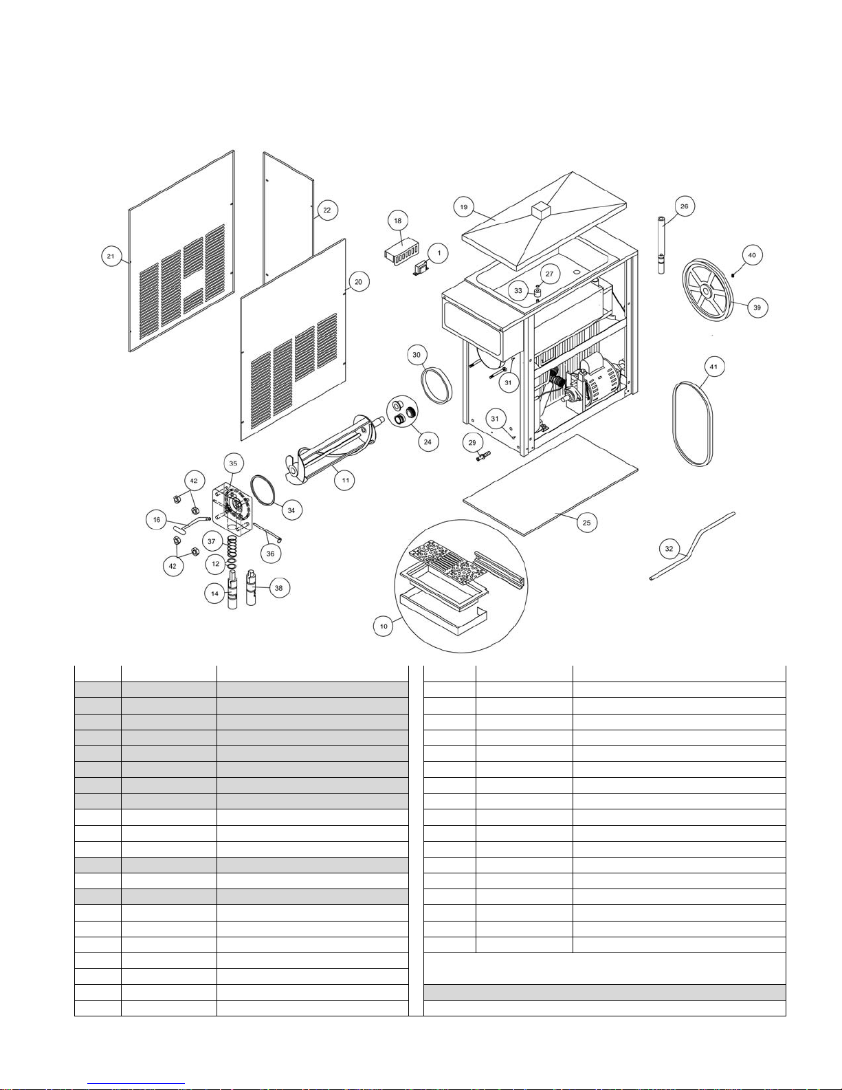
Model 3311
Page 17
Exploded View
XF124
220V Air-Cooled Model
ITEM PART NUMBER DESCRIPTION ITEM PART NUMBER DESCRIPTION
1 W0570045 BALLAST 25 W0470010 PAD, NEOPRENE RUBBER
2 W0600110 OWNERS MANUAL 26 W0471076 FEED TUBE ASSY, SLUSH/COCKTAIL
4 W0660060 PLASTIC SHIPPING BAG 27 W0340007 O-RING, #108 FLOAT
5 W0600121 HEADER INSTALL INSTR SHEET 29 W0211112 DRAIN TUBE FITTING
6 W0600073 CAUTION RUBBER MAT 30 W0340058 BARREL GASKET
7 W0631903 SANITIZER PACKETS 31 W0630518 RICHCO HOLE PLUG
8 W0600159 WARRANTY CARD 32 W0641027 DRAIN TUBE HOSE
9 W0801023 PACKAGING ASSEMBLY 33 W0570941 MIX LOW IND FLOAT
10 W0890218 DRIP PAN KIT 34 W0340055 SQUARE CUT O-RING
11 W0430026 STANDARD BEATER BAR 35 W0480450 VALVE BODY
12 W0340022 O-RING, #213 36 W0611728 FASPIN
13 WO470076 LUBRICANT, LUBRIFILM SANITARY 37 W0631205 COMPRESSION SPRING
14 W0480438 PLUNGER, STANDARD PRODUCT 38 WO480451 PLUNGER, THICK P RO DUCT
15 WO610127 PANEL SCREWS 39 W0450053 10” PULLEY
16 WO480455 HANDLE, VALVE 40 W0610646 SCREW, SET, 5/16-18 X 3/8
18 WO211086 BALLAST COVER 41 W0450209 V-BELT
19 W0520094 HOPPER COVER 42 W0630711 VALVE KNOB
20 W0520065 R.H. SIDE PANEL
21 W0520107 L.H. SIDE PANEL
22 WO520063 REAR PANEL ITEM NOT SHOWN IN DRAWING
24 W0890187 STANDARD SEAL KIT
Page 15
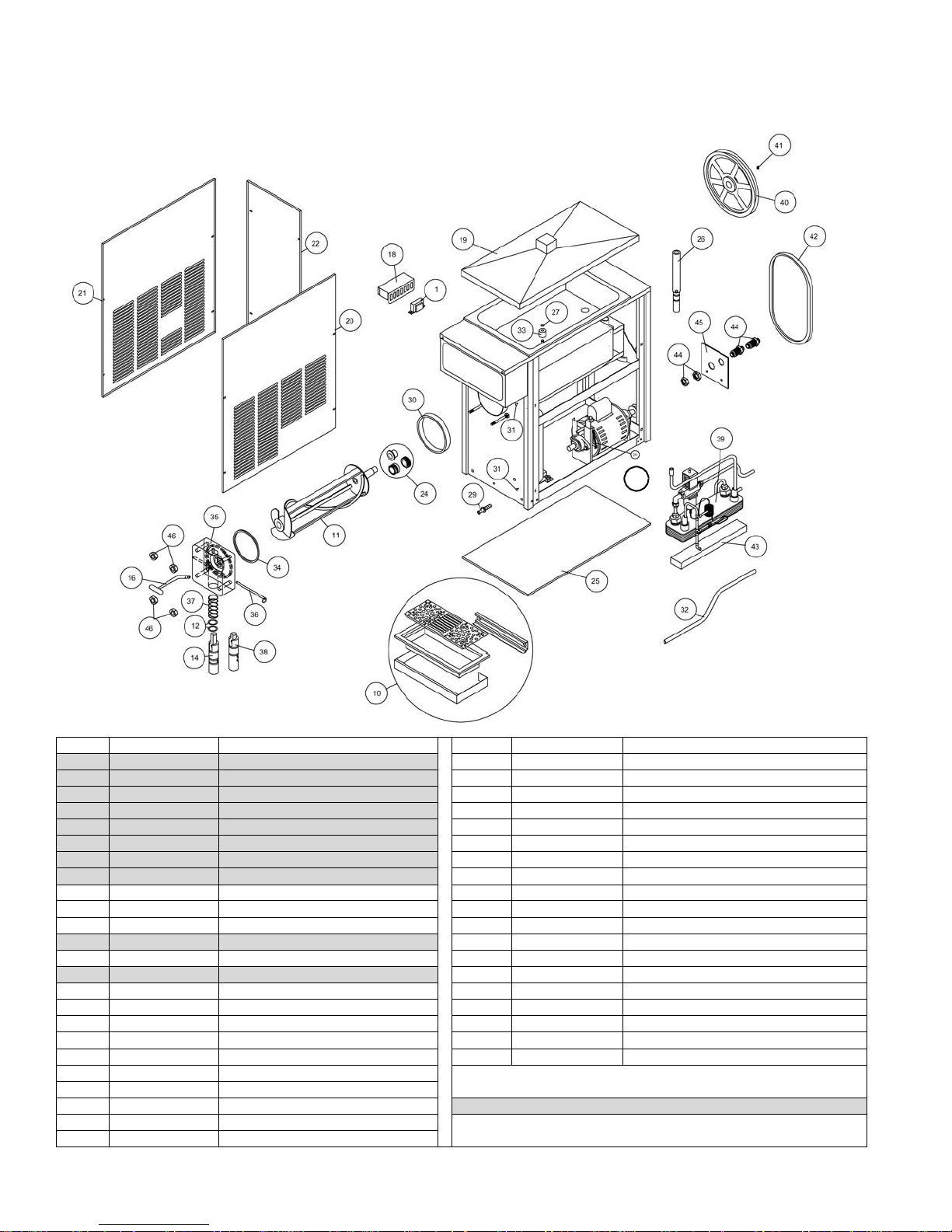
Page 18
Model 3311
Exploded View
ITEM
PART NUMBER
DESCRIPTION
ITEM
PART NUMBER
DESCRIPTION
1
W0570045
BALLAST
27
W0340007
O-RING, #108 FLOAT
2
W0600110
OWNERS MANUAL
29
W0211112
DRAIN TUBE FITTING
4
W0660060
PLASTIC SHIPPING BAG
30
W0340058
BARREL GASKET
5
W0600121
HEADER INSTALL INSTR SHEET
31
W0630518
RICHCO HOLE PLUG
6
W0600073
CAUTION RUBBER MAT
32
W0641027
DRAIN TUBE HOSE
7
W0631903
SANITIZER PACKETS
33
W0570941
MIX LOW IND FLOAT
8
W0600159
WARRANTY CARD
34
W0340055
SQUARE CUT O-RING
9
W0801023
PACKAGING ASSEMBLY
35
W0480450
VALVE BODY
10
W0890218
DRIP PAN KIT
36
W0611728
FASPIN
11
W0430026
STANDARD BEATER BAR
37
W0631205
COMPRESSION SPRING
12
W0340022
O-RING, #213
38
W0480451
PLUNGER, THICK PRODUCT
13
W0470076
LUBRICANT, LUBRIFILM SANITARY
39
W0200180
CONDENSER ASSEMBLY
14
W0480438
PLUNGER, STANDARD PRODUCT
40
W0450053
10” PULLEY
15
W0610127
PANEL SCREWS
41
W0610646
SCREW, SET, 5/16-18 X 3/8
16
W0480455
HANDLE, VALVE
42
W0450209
V-BELT
17
W0631239
SPRING, CONSISTENCY (RED)
43
W0210062
CONDENSER PAD
18
W0211086
BALLAST COVER
44
W0620036
BULKHEAD FITTING WITH JAM NUT
19
W0520094
HOPPER COVER
45
W0210051
WATER LINE SUPPORT BRACKET
20
W0520065
R.H. SIDE PANEL
46
W0630711
VALVE KNOB
21
W0520107
L.H. SIDE PANEL
22
W0520058
REAR PANEL W/C
24
W0890187
STANDARD SEAL KIT
ITEM NOT SHOWN IN DRAWING
25
W0470010
PAD, NEOPRENE RUBBER
26
W0471076
FEED TUBE ASSY, SLUSH/COCKTAIL
XF124
115V Water-Cooled Model
17
Page 16
Model 3311
Page 19
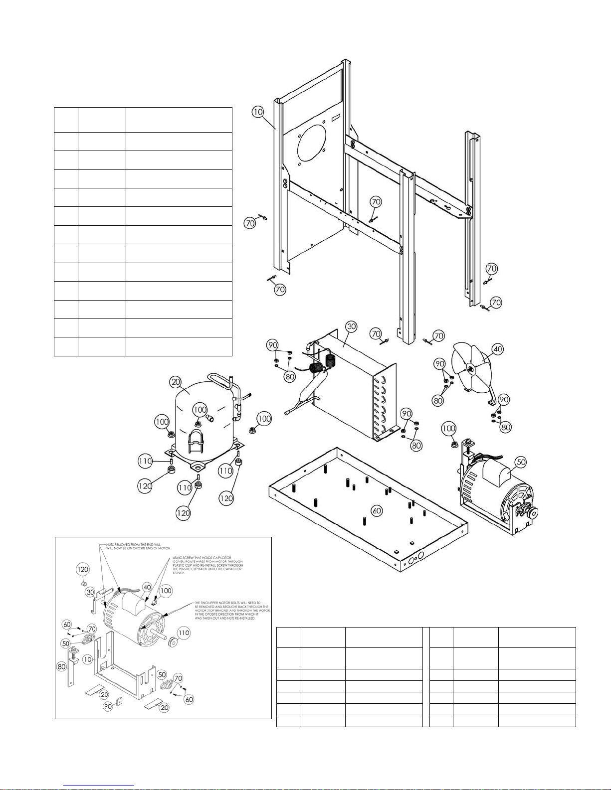
XF124
PART
PART
1/4 Split Lock
20
W0671022
Motor Sound Insul.
80
W0170014
Consistency Control
30
W0321025
Motor Stop Bracket
90
W0321013
Motor Adj. Nut
40
W0320020
Drive Motor
100
W0630421
Plastic Clamp
50
W0380009
Flange Bearing
110
W0450016
Pulley
60
W0610559
1/4-20 Socket HD
120
W0321027
Pin Sleeve
Base Assembly
115V Air-Cooled Model
ITEM
10 W0210083 FRAME ASS EMBLY
20 W0201001 COMPRESSOR ASSEMBLY
30 W0201002 CONDENSER ASSEMBLY
40 W0321029 FAN SUB-ASSEMBLY
50 W0321026 DRIVE MOTOR ASSEMBLY
60 W0210106 BASE PAN ASSEMBLY
70 W0611410 RIVET, MAGNA-LOK
80 W0611247 1/4 INT. TOOTH LK. WSHR.
90 W0611074 1/4-20 HEX NUTS
100 W0611082 5/16-18 FLANGE NUT
110 W0200412 COMPRESSOR SPACER
120 W0200413 COMPRESSOR GROMMET
PART
NUMBER
DESCRIPTION
Drive Motor Assembly (See figure on left)
ITEM
NUMBER
10 W0210169 Motor Cradle
DESCRIPTION
ITEM
70 W0611249
NUMBER
DESCRIPTION
Washer S.S.
Page 17
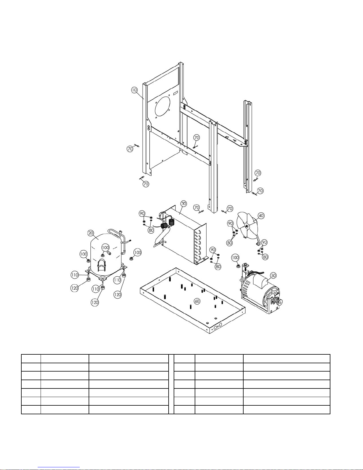
Page 20
Model 3311
XF124
ITEM
PART NUMBER
DESCRIPTION
ITEM
PART NUMBER
DESCRIPTION
10
W0210083
FRAME ASSEMBLY
70
W0611410
RIVET, MAGNA LOCK
20
W0201007
COMPRESSOR ASSEMBLY
80
W0611247
1/4 INT. TOOTH LK. WSHR.
30
W0201002
CONDENSER ASSEMBLY
90
W0611074
1/4-20 HEX NUTS
40
W0321040
FAN SUB-ASSEMBLY
100
W0611082
5/16-18 FLANGE NUT
50
W0321041
DRIVE MOTOR ASSEMBLY
110
W0200412
COMPRESSOR SPACER
60
W0210106
BASE PAN ASSEMBLY
120
W0200413
COMPRESSOR GROMMET
Base Assembly
220V Air-Cooled Model
Page 18
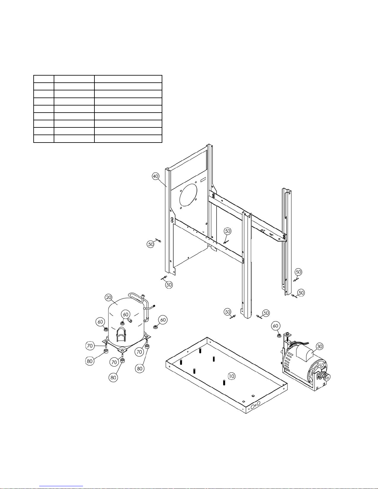
Model 3311
Page 21
XF124
Base Assembly
115V Water-Cooled Model
ITEM PART NUMBER DESCRIPTION
10 W0210068 BASE PAN
20 W0201001 COMPRESSOR ASSEMBLY
30 W0321026 DRIVE MOTOR ASSEMBLY
40
50
60 W0611082 5/16-18 FLANGE NUT
70 W0200412 COMPRESSOR SPACER
80 W0200413 COMPRESSOR GROMMET
* See condenser assembly on page 34.
W0210083 FRAME ASSEMBLY
W0611410 RIVET, MAGNA LOCK
Page 19
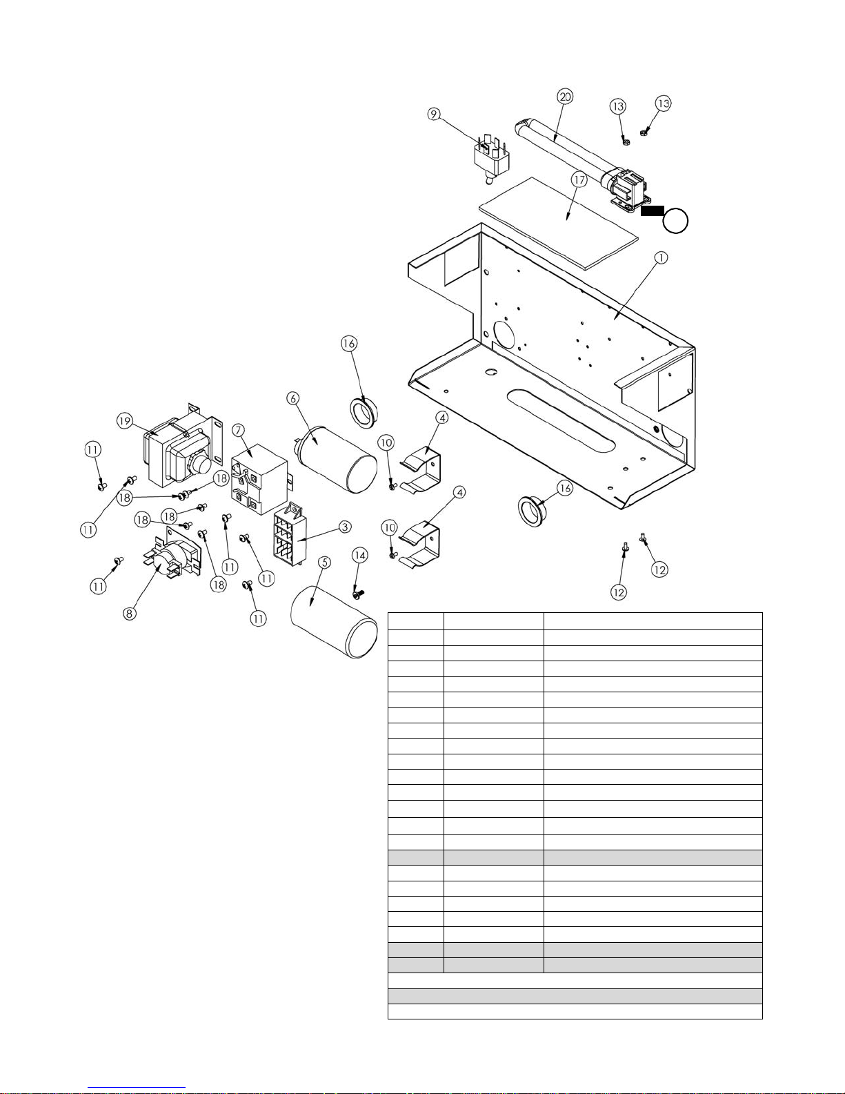
Page 22
Model 3311
XF124
Electrical Box Assembly
115V Model (AC/WC Units)
ITEM PART NUMBER DESCRIPTION
1 W0572287
2 W0570044
3 W0570235
4 W0630811
5 W0570603
6 W0570617
7 W0570638
8 W0570651
9 W0570924
10 83248
11 W0610131
12 W0610015
13 W086827
14 61272
15 83151
16 W0630006
17 W0631606
18 W0610132
19 W0572032
20 W0570043
22 W0572192
23 W0571000
ITEM NOT SHOWN IN DRAWING
ELECTRICAL BOX
SOCKET, LIGHT-LEVITON
BLOCK, TERMINAL 4
CLIP, CAPACITOR - SMALL
START CAPACITOR
RUN CAPACITOR
RELAY, COMPRESSOR
HEAT SEQUENCER
SWITCH, TOGGLE-SPST
6-32 X 1/4” SCREW
8-32 X 1/4” SCREW
6-32 X 1/4” SCREW
6-32 HEX NUT
SCRW, #8 X 3/8 PH PN T/B ZNC/GN
WASHER, LOCK, #8, EXT. TOOTH
HEYCO SNAP BUSHING
ELECTRICAL BOX LENS
8-32 X 1/4” SCREW
TRANSFORMER SUB-ASSY
BULB, FLUORESCENT
SUB-ASSY, MIX LOW INDICATOR, WIR E
HARNESS, WIRE, 3311
2
Page 20
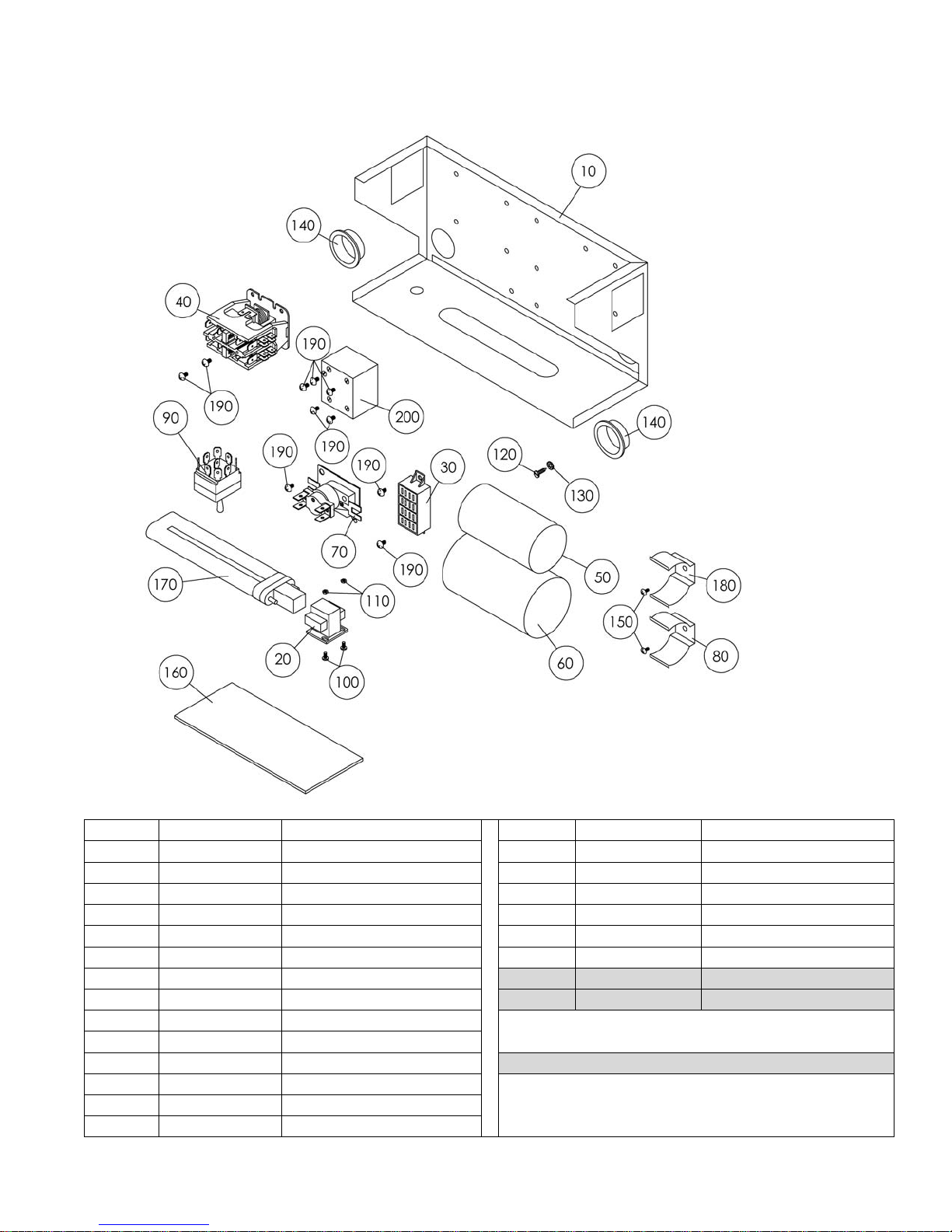
Model 3311
Page 23
XF124
ITEM
PART NUMBER
DESCRIPTION
ITEM
PART NUMBER
DESCRIPTION
10
W0572287
ELECTRICAL BOX
150
83248
6-32 X 1/4 TRUSS HEAD
20
W0570054
LIGHT SOCKET
160
W0631606
LIGHTED ELEC. BOX LENS
30
W0570235
TERMINAL BLOCK
170
W0570055
BULB
40
W0570635
CONTACTOR
180
W0630811
CLIP, CAPACITOR (SMALL)
50
W0570667
RUN CAPACITOR
190
W0610131
8-32 X 1/4 SCREW
60
W0570666
START CAPACITOR
200
W0570876
COMPRESSOR RELAY
70
W0570651
HEAT SEQUENCER
210
W0572192
MIX LOW W IRE SUB-ASSY
80
WO630812
CLIP, CAPACITOR
230
W0571000
WIRE HARNESS 3311
90
W0570940
TOGGLE SWITCH
100
W0610015
6-32 X 1/4 SLOTTED SCREW
110
86827
6-32 HEX NUT Z/P
ITEM NOT SHOWN IN DRAWING
120
61272
#8 GROUND SCREW
130
W0611224
#8 EXTERNAL STAR WASHER
140
W0630006
HEYCO BUSHING
Electrical Box Assembly
220V Air-Cooled Model
Page 21
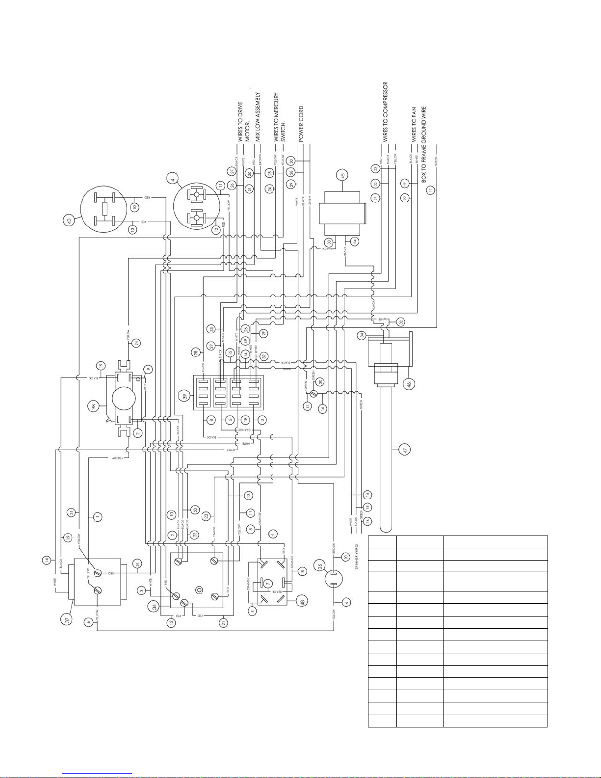
Model 3311
Page 24
XF124
Wiring Diagram
115V Air-Cooled Model
ITEM PART NO. DESCRIPTION
35 W0570018 INDICATOR LIGHT
36 W0570638 COMPRESSOR RELAY
37 W0572032
38 W0570651 TIME DELAY RELAY
39 W0570235 TERMINAL BLOCK
40 W0570603 START CAPACITOR
41 W0570617 RUN CAPACITOR
42 W0572192 MIX LOW SUB-ASSY.
43 W0572068 POWER CORD
44 W0630801 TIE WRAPS
45 W0570045 BALLAST
46 W0570044 LIGHT SOCKET
47 W0570043 LIGHT BULB
48 W0570924 SWITCH
TRANSFORMER
SUB-ASSY
Page 22
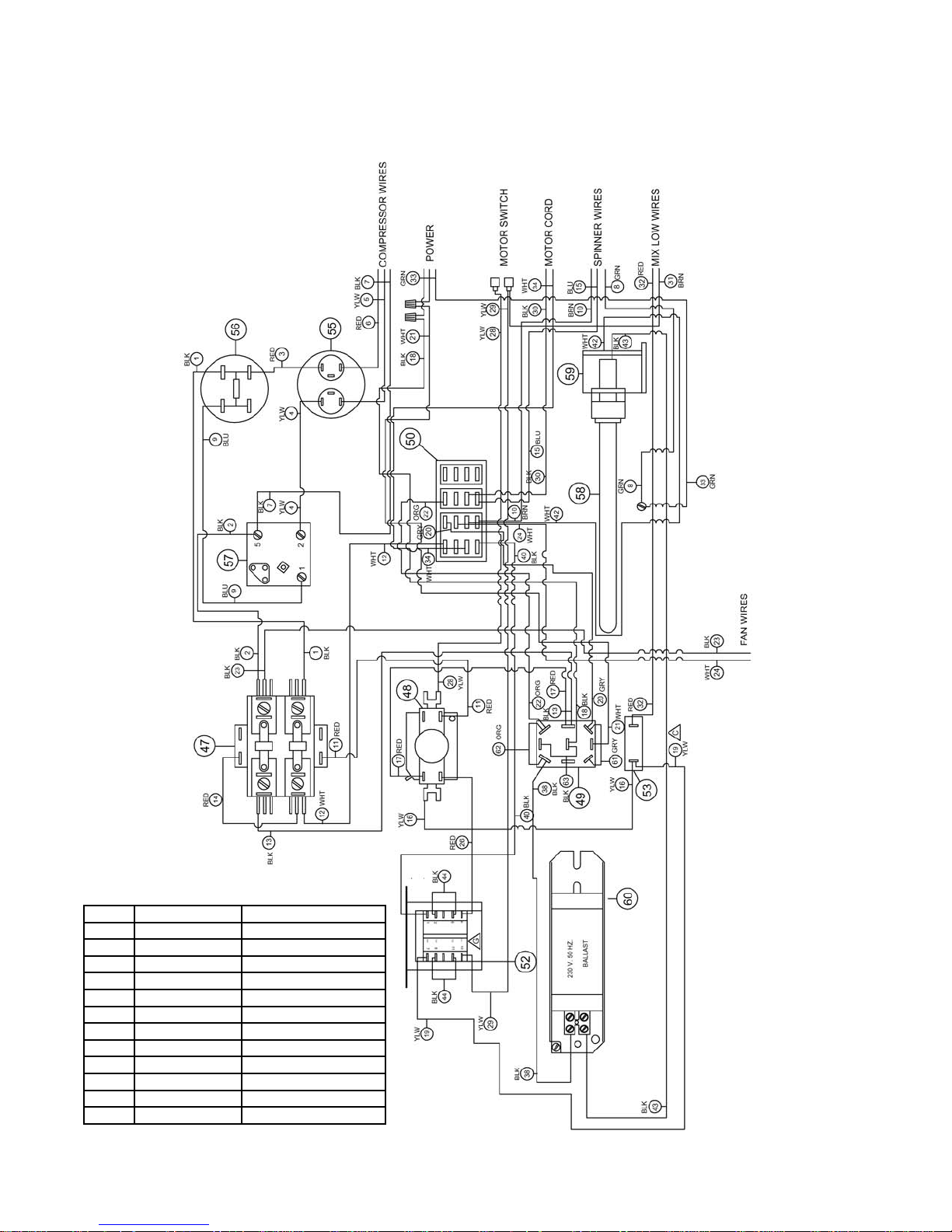
Page 24
Model 3311
XF124
ITEM
PART NUMBER
DESCRIPTION
47
W0570872
CONTACTOR RELAY
48
W0570651
TIME DELAY RELAY
49
W0570940
TOGGLE SWITCH
50
W0570235
TERMINAL BLOCK
52
W0570871
TRANSFORMER
53
W0570018
INDICATOR LIGHT
55
W0570667
RUN CAPACITOR
56
W0570666
START CAPACITOR
57
W0570559
COMPRESSOR RELAY
58
W0570055
LIGHT BULB
59
W0570054
LIGHT SOCKET
60
W0570053
50 HZ BALLAST
Wiring Diagram
220V Air-Cooled Model
Page 23
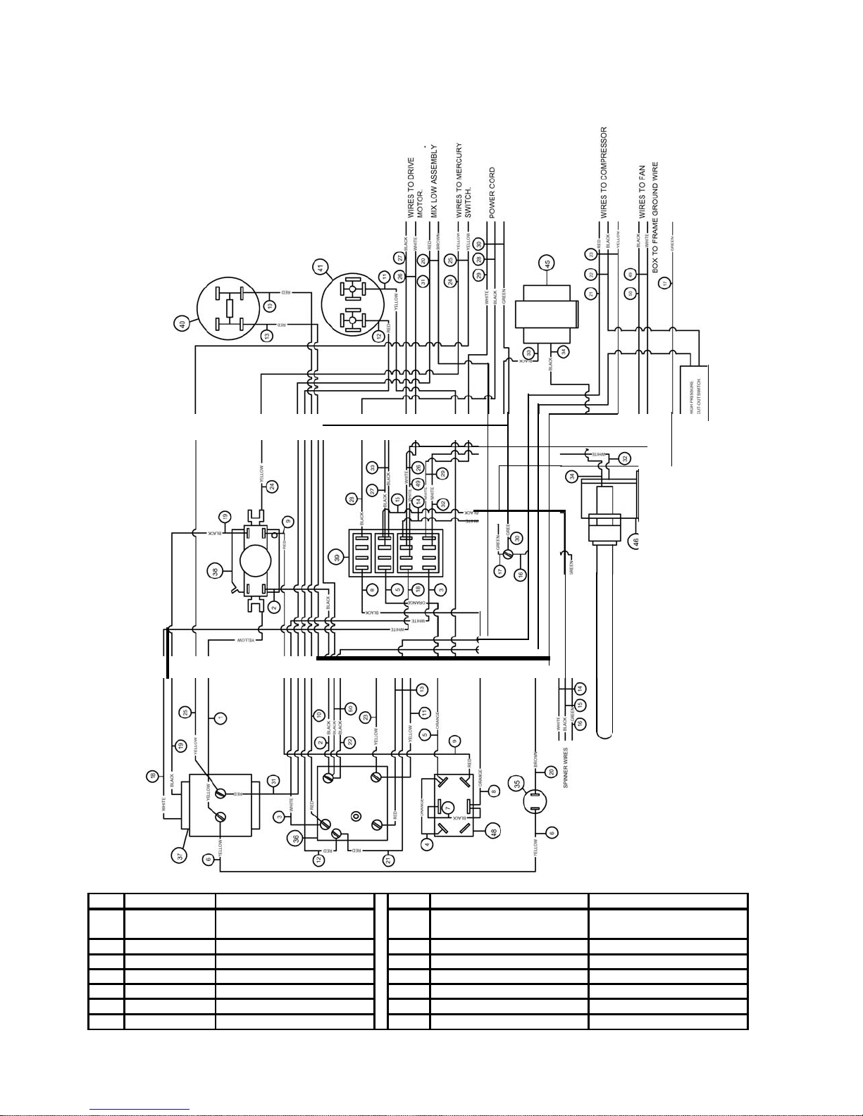
Model 3311
Page 26
-
XF124
ITEM PART
NUMBER
DESCRIPTION
ITEM PART
NUMBER
DESCRIPTION
49
HIGH
PRESSURE
48 W0570924
SWITCH
40 W0570603
START
CAPACITOR
47 W0570043
FLORESCENT
LIGHT
BULB
39 W0570235
TERMINAL
BLOCK
46 W0570044
LIGHT
SOCKET
38 W0570651
TIME DELAY
RELAY
45 W0570045
CORE & COIL
BALLAST
37 W0572032
TRANSFORMER SUB-ASSY
43 W0572068
POWER
CORD
36 W0570638
COMPRESSOR
RELAY
42 W0572192
LOW MIX
SUB-ASSY
35 W0570007
INDICATOR
LIGHT
Wiring
Water-Cooled
Diagram
Model
l
W0650428
CUT-OUT
SWITCH
41
W0570604
RUN
CAPACITOR
Page 24
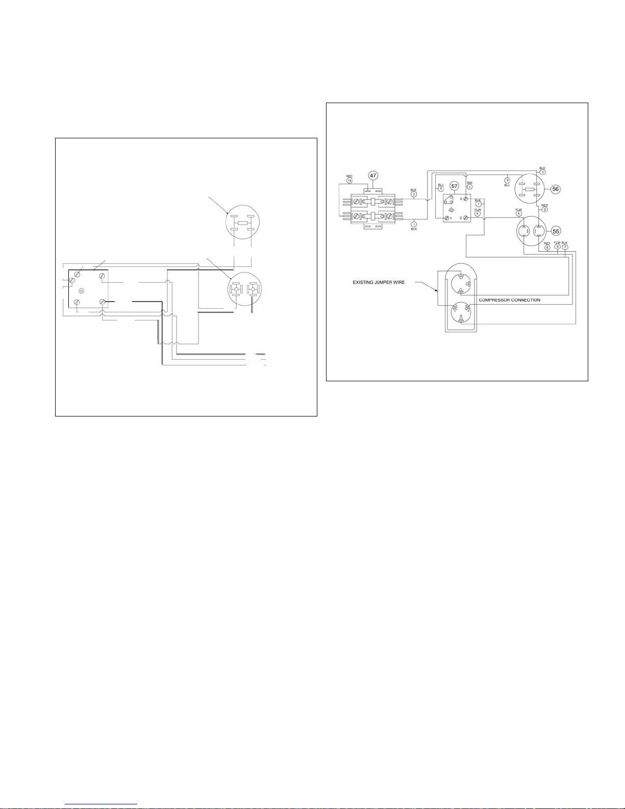
RED
RED
RED
RED
XF124
Compressor Wiring
START CAPACITOR
COMPRESSOR RELAY
RED
BLACK
YELLOW
RED
YELLOW
115V Air-Cooled Model 220V Air-Cooled Model
RUN CAPACITOR
RED
YELLOW
RED
BLACK
YELLOW
WIRES TO
COMPRESSOR
Page 25
Page 28
Model 3311
XF124
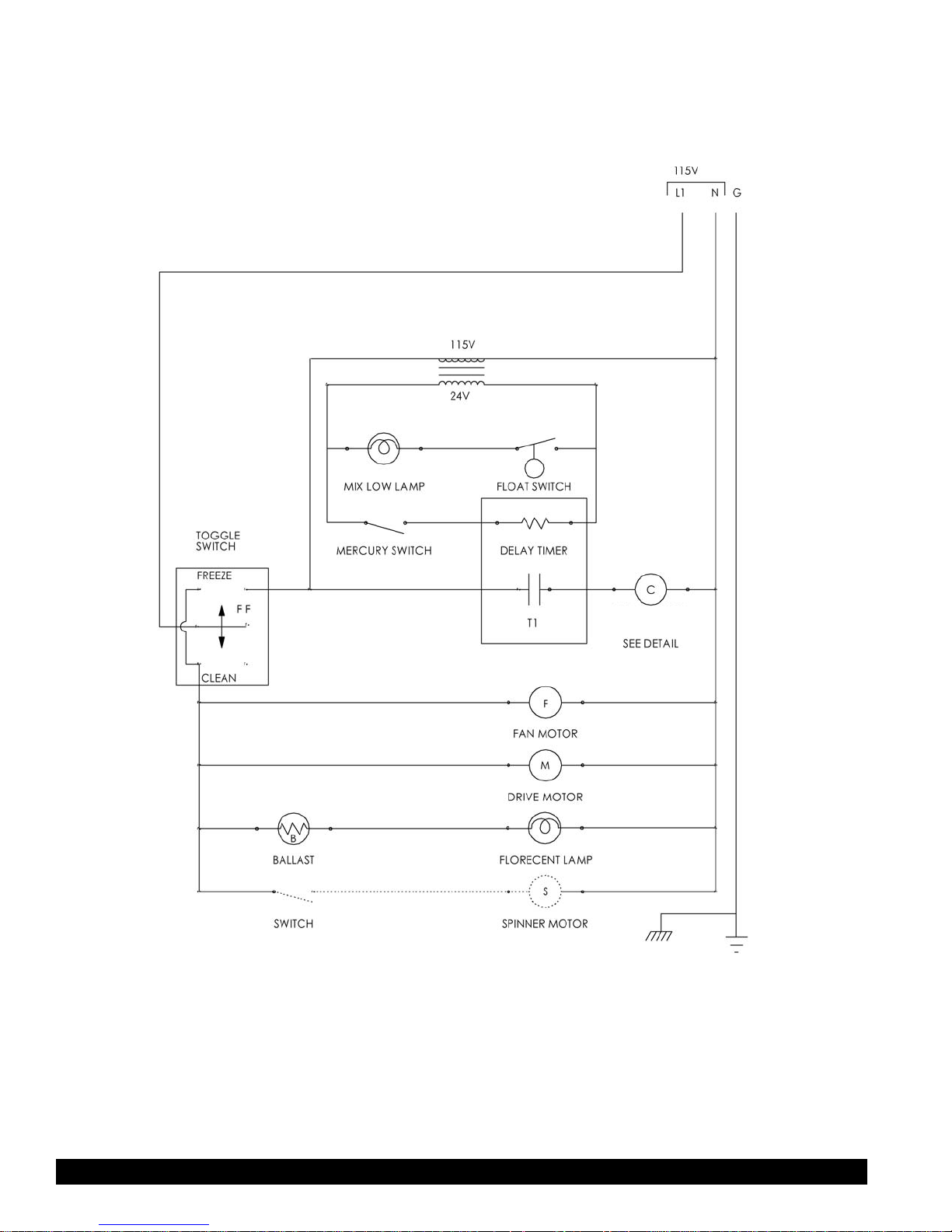
Ladder Diagram
115V Air-Cooled Model
COMPRESSOR
CONTACT
Page 26
XF124
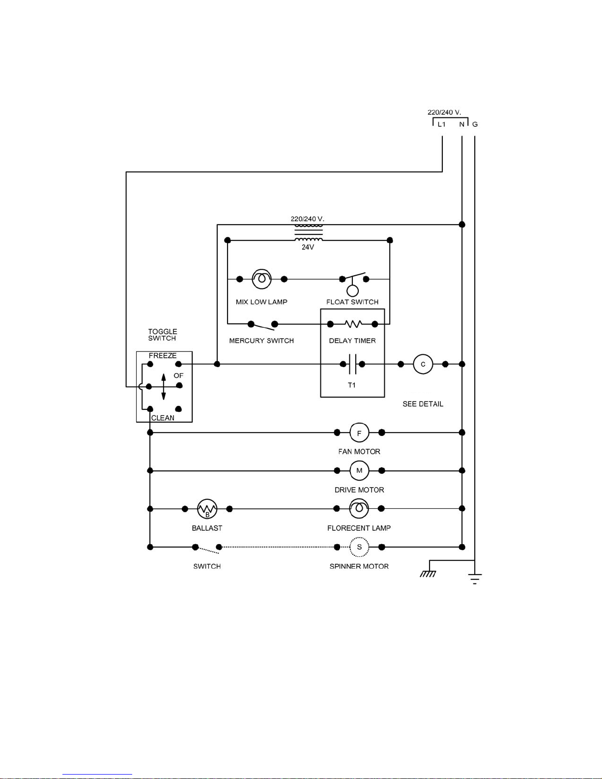
Ladder Diagram
220V Air-Cooled Model
COMPRESSOR
CONTACT
Page 27
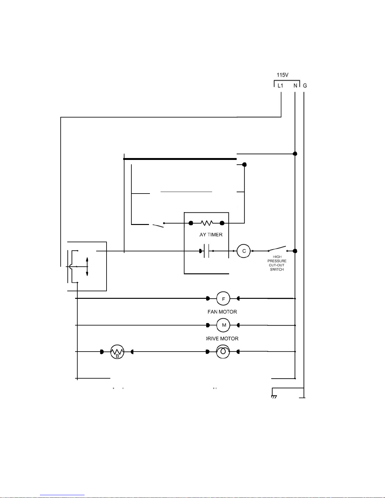
T1
XF124
Ladder
115V Water-Cooled
Diagram
TOGGLE
SWITCH
FRE
EZE
Model
MIX
LOW LAMP FLOAT SWITCH
MERCURY SWITCH DELAY TI
1
15V
2
4V
MER
0
F
CLEAN
DRIVE
MOTO
COMPRESSOR
CONTACT
SEE
DETAIL
R
BALLAST
.....
....
..................
SWITCH
........
....................
.................... ...{.
FLORECENT LAMP
···
...
....·:;.·-
----------4
SPINNER MOTOR
Page 28
Page 31
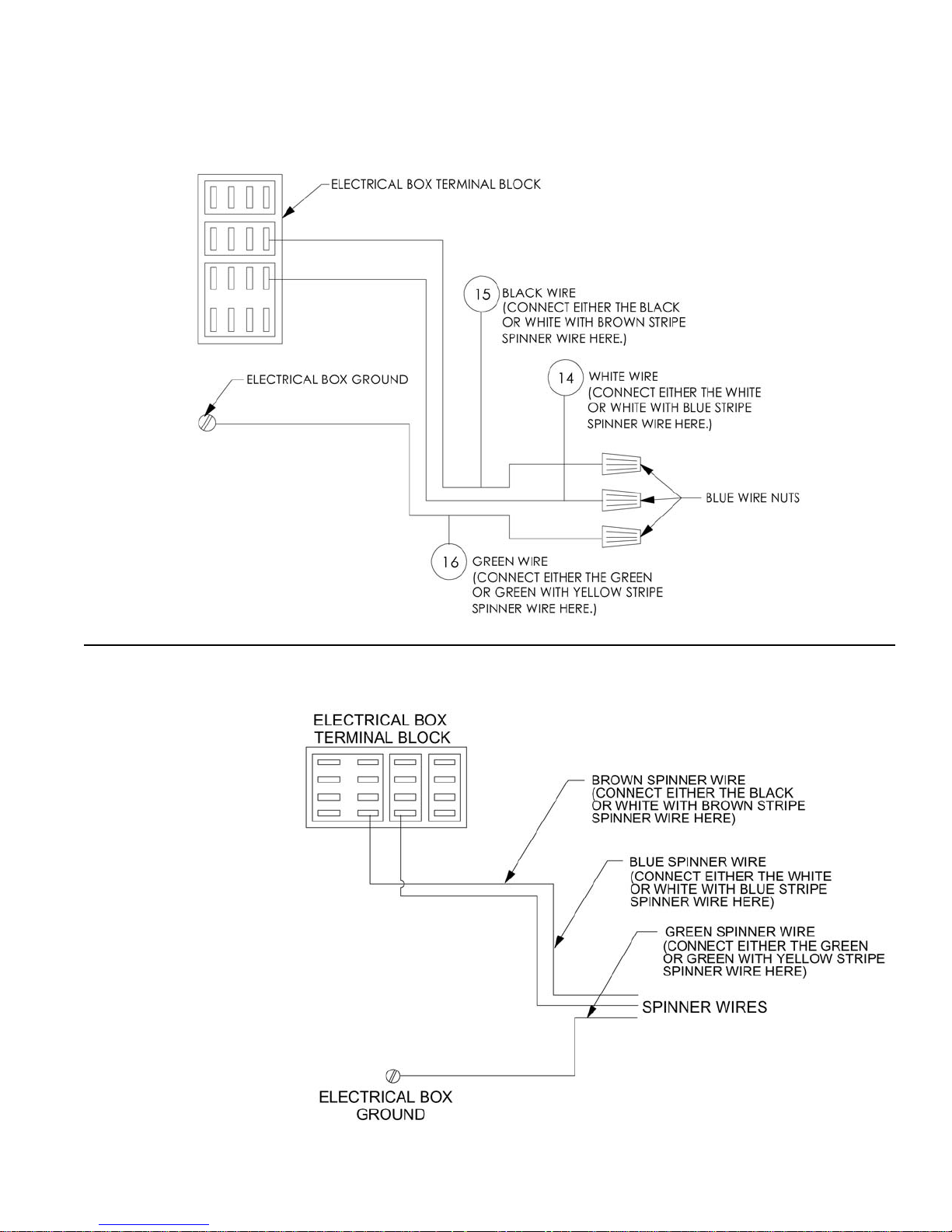
XF124 (AC/WC Units)
Spinner Hook-Up
115V Model
XF124
Spinner Hook-Up
220V Model
Page 29
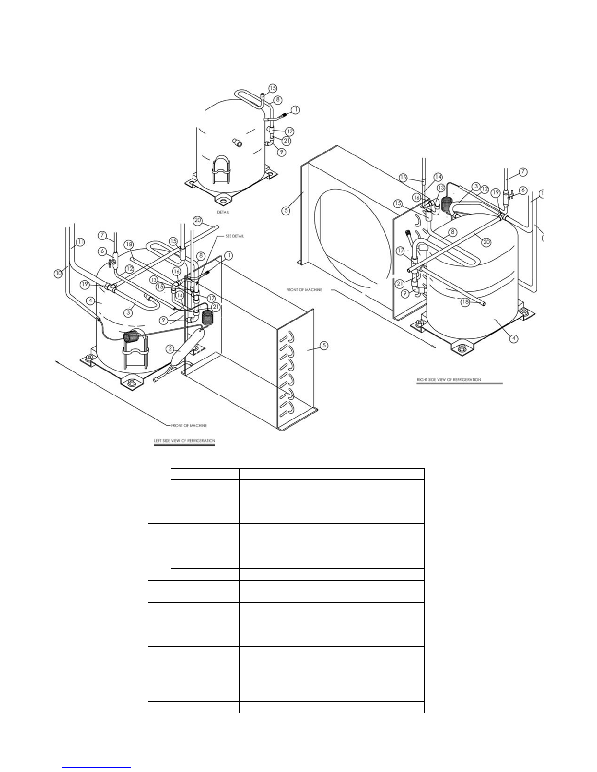
XF124
ITEM
PART
NUMBER
DESCRIPTION
1
W0650501
ACCESS VALVE
2
W020031 1
DRIER/CAP
TUBE
ASSEMBLY
3
W0201191
SUCTION LINE
4
W02001 23
COMPRESSOR
5 W0200256
CONDENSER
6
W06504 1
6
NEEDLE
VALVE
7
----
HOPPER
COOLANT
LINE
8
W0201009
HOT GAS LINE
9
W06201 1 2
3/8"
COPPER ELBOW
10
-----
EVAPOR ATOR LINE
11
----
SUCTION LINE
12
W0201133
COOLANT
LINE
13 W0620l07
90 DEG.
STREET
ELBOW
14
W020115
1
3/8"
COND. CONNECTION
15
W0620103
3/8"
COPPER COUPLE
16
W0201152
5/ 1 6 X 3/8
RED. COUPL
E
17
W0620114
3/8"
COPPER TEE
18
W0201006
HIGH
SIDE PROCESS
TUBE
19
W0620l06
1
/2
X 3/8 X 3/8 COPPER TEE
20
W0201008
LOW
SIDE PROCESS TUBE
21
W0201004
HOT GAS EXTENSION
Refrigeration
115V Air-Cooled
Model
SHEEJ20F2
Page 30
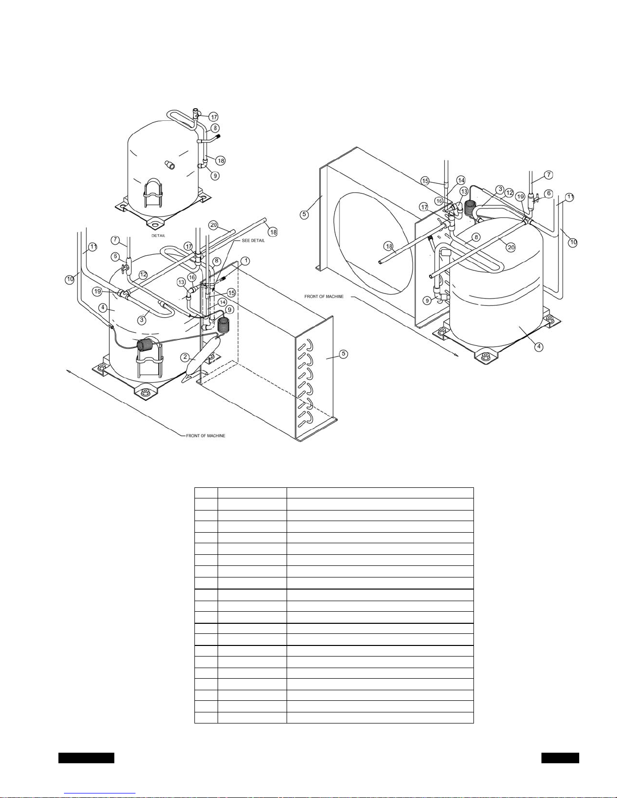
Model 3311
Page 33
XF124
ITEM
1 W0650501
ACCESS VALVE
2 W0200310
DRIER/CAP TUBE ASSEMBLY
3
W0201191
SUCTION LINE
4 W0200132
COMPRESSOR
5 W0200256
CONDENSER
6 W0650416
NEEDLE VALVE
7
................
HOPPER COOLANT LINE
8 W0201009
HOT GAS LINE
9
W0620112
3/8" COPPER ELBOW
10
-------
EVAPORATOR LINE
11
................
SUCTION LINE
12 W0201133
COOLANT LINE
13 W0620107
90
DEG. STREET ELBOW
14 W0201151
3/8" COND. CONNECTION
15
W0620103
3/8" COPPER COUPLE
16
W0201152
5/16 X 3/8 RED. COUPLE
17 W0620114
3/8" COPPER
TEE
18 W0201006
HIGH SIDE PROCESS
TUBE
19
W0620106
1/2 X 3/8 X 3/8 COPPER TEE
20
W0201008
LOW SIDE PROCESS TUBE
Refrigeration
220V Air-Cooled
Model
lEFT
SlOE
VIEW OF
REtAIGEAATION
PART
NUMBER
DESCRIPTION
RIGHT SIJE
VIEW
Of REfRKlERATION
Page 31
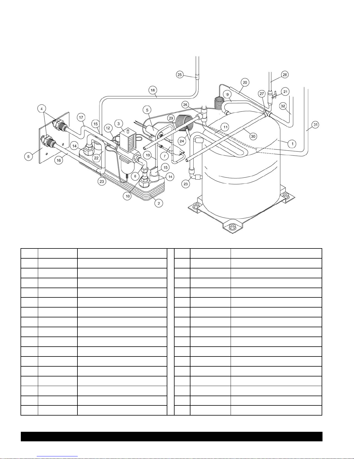
Page 34
Model 3311
XF124
ITEM
PART NUMBER
DESCRIPTION
ITEM
PART NUMBER
DESCRIPTION
1
W0200123
COMPRESSOR
17
W0201166
WATER LINE
2
W0200250
CONDENSER, WATER COOLED
18
W0201167
COOLANT LINE
3
W0650602
WATER VALVE, 3/8 V-46 AA-1C
19
W0201162
COOLANT LINE ASSEMBLY
4
W0620031
BULKHEAD FITTING WITH JAM NUT
20
W0201133
COOLANT LINE
5
W1650401
HIGH PRESSURE CUT OUT
21
W0650416
NEEDLE VALVE
6
W0210051
WATER LINE SUPPORT BRACKET
22
W0201164
WATER LINE
7
W0200311
DRIER CAPILLARY TUBE ASSEMBLY
23
W0620112
3/8 X 3/8 COPPER SWEAT ELBOW
8
W0620031
90 DEG. ELBOW X 3/8 NPT & 3/8 FLARE
24
W0650501
ACCESS VALVE
9
W0201191
SUCTION LINE
25
W0620103
3/8” COPPER COUPLE
10
W0201169
WATER LINE
26
W0620114
3/8” COPPER TEE
11
W0201009
HOT GAS LINE
27
W0620106
1/2 X 3/8 X 3/8 COPPER TEE
12
W0620033
FITTING, 3/8 FLARE X 3/8 NPT
28
--------------
HOPPER COOLANT LINE
13
W0620101
1/4 COPPER SWEAT COUPLING
29
W0201006
HIGH SIDE PROCESS TUBE
14
W0620053
3/4 NPT X 38 FLARE FITTING
30
W0210008
LOW SIDE PROCESS TUBE
15
W0201250
CONDENSER CONNECTION
31
---------------
EVAPORATOR LINE
16
W0201165
WATER LINE
32
---------------
SUCTION LINE
Refrigeration
115V Water-Cooled Model
Page 32
Model 3311
Page 35
- >
;;
z
-
0
z
w
z
1
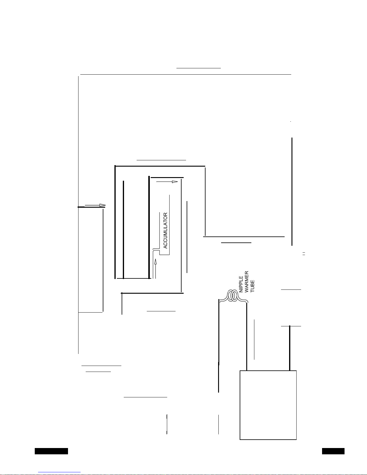
XF124
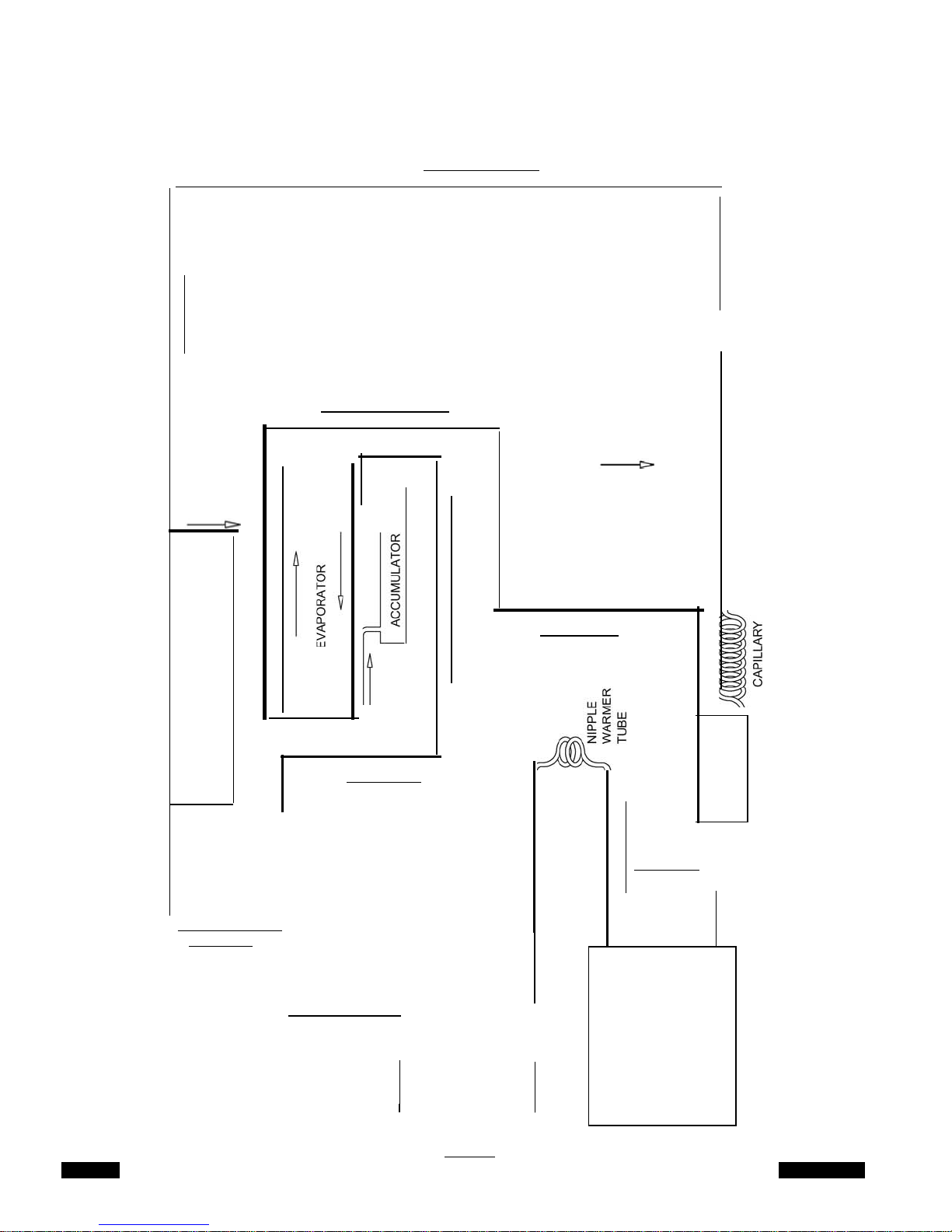
Refrigeration Schematic (AC
115V & 220V
r-
I
I
Models
-----------------------------------------------------------------,
j
0
o._
UJ
Units)
w w
'
0
-'
w<
w
>
z
A
lll
d'<t::l
1
>-
0:::
<{
J
J
0:::
UJ
o._
o._
0
I
0::
UJ
cr
0
<{
(.)
-------- -
_.....J
r:::-
0
i=
(.)
z::J
(/)
0:::
(/)
(/)
I
0:::
o._
::2
0
(.)
UJ
(.9
0:::
<{
I
(.)
I-
(/)
::J
0
0
0:::
w
(/)
w
0
I
0
(.)
1
Page 33
Page 36
Model 3311
I
I
z
1
0
1
()
-
0
XF124
Refrigeration
Water-Cooled
r- -----------------------------------------------------------------,
Schematic
Model
a::
UJ
(L
(L
0
I
WUJ
...J>
O
..J
w.<
w>
z
I
I
I
I
I
I
I
I
I
I I
I
I
I
I
I
I
I
I
I
I
I
I
I
I
I
I
A
-
\nlld\7'::>
I
I
I
I
I
I
I
I
I
I
I
I
I
I
I
I
I
I
I
I
I
I
I
I
I
I
I
I
I
I
I
--'
1
a::
w
cr.
0
,_
-
----- - -------------------------------
c::-
C>-
1
UJ
0::
::>
0
<(
I
t-
(/)
z
0
i=
()
z::>
(/)
0::
0
(/)
(/)
w
0::
(L
:2
0
()
H !IMS
3MnSS3Md
a::
UJ
(/)
UJ
0
z
0
()
 Loading...