

Page 1

DNC(Dmax Network Camera) User's Manual Part1
DNC 1 Dongyang Unitech Co., Ltd
DNC(Dmax Network Camera) User’s Manual
Part 1
(Product Overview)
Version 4.0
Dongyang Unitech Co., Ltd
www.d-max.co.kr
www.cctvhome.net
Page 2

DNC(Dmax Network Camera) User's Manual Part1
DNC 2 Dongyang Unitech Co., Ltd
Contents
1. Product Overview ............................................................................................................................... 3
1.1. DNC IP Camera .............................................................................................................................. 3
1.2. Key Features .................................................................................................................................. 4
1.3. Technical Specification of DNC IP Camera .................................................................................... 5
1.4. DNC IP Camera Packing List ......................................................................................................... 7
2. Hardware Description ......................................................................................................................... 8
2.1. DNC IP Camera .............................................................................................................................. 8
3. DNC IP Camera HW installation and basic setup .............................................................................. 8
3.1. Before installation ........................................................................................................................... 8
3.2. Factory Default Condition ............................................................................................................... 8
3.3. Hardware installation ...................................................................................................................... 9
Page 3
DNC(Dmax Network Camera) User's Manual Part1
DNC 3 Dongyang Unitech Co., Ltd
1. Product Overview
1.1. DNC IP Camera
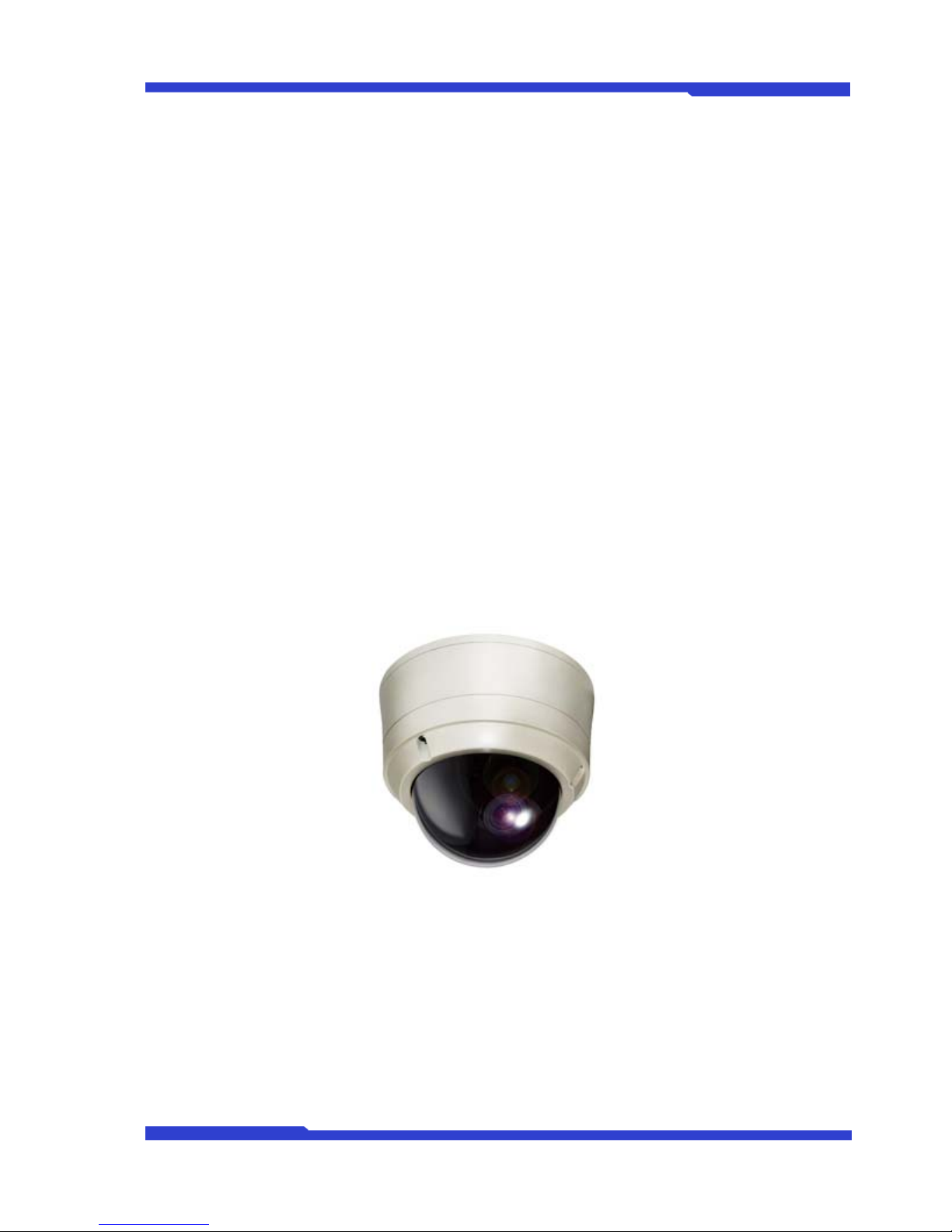
DNC® IP Camera is a standalone network camera that has a built-in PTZ Analog Camera and is capable
of transmitting the video over the IP Network. IP Camera has built-in web server, so it can transmit the
video at the rate of up to 30fps (NTSC@4CIF) over the network such as LAN, leased line, DSL or Cable
modem. Users can monitor the video transmitted from IP Camera on web browser such as Internet
Explorer or Firefox.
DNC IP Camera supports video compression format of both Motion-JPEG and H.264, and it can encode
the video signal into the two different video formats and transmit them over the network at the same time.
This way, users have the choice which video format to use for their intention. DNC IP Camera supports
both NTSC and PAL standards, and users can select from 5 different video resolutions and 6 levels of
video qualities.
Picture 1 : FW-1177-DE
Page 4

DNC(Dmax Network Camera) User's Manual Part1
DNC 4 Dongyang Unitech Co., Ltd
1.2. Key Features
• Standalone device with built-in web server
• 10/100Base-T Auto-Sensing Ethernet
• Configuring and controlling through Web browser
• Up to 30 fps transmission rate on TCP/IP network
• Effective Bandwidth & Bit-rate Control (VBR/CBR) by H.264
• Dual Streaming in Motion JPEG and H.264
• 1-channel Voice Encoding / 1-channel Voice Decoding
• Built-in 2 way Audio transmission (1ch A-in, 1 A-out)
• Support Dynamic-IP users by IPCCTVDNS server
• Support PTZ (Pan/Tilt/Zoom) functions
• Support Sensor Input, Digital Output
• Support transparent mode
• Encryption on user authentication level
• Support dialup modem (Dial-in, Dial-out)
• Image transmission via FTP and Email
Page 5

DNC(Dmax Network Camera) User's Manual Part1
DNC 5 Dongyang Unitech Co., Ltd
1.3. Technical Specification of DNC IP Camera
Hardware
32bit Embedded CPU
Flash 8Mbytes / SDRAM: 128Mbytes
Linux version 2.6.xx operating system
Battery backed-up real-time clock
Image Sensor
1/4”Sony 410K Super HAD CCD
Resolution: 520 TV Lines
[Detail]
S/N ratio: 50dB or more (AGC OFF)
Electronic shutter speed:
1/60 ~ 1/100,000 sec (NTSC)
1/50 ~ 1/100,000 sec (PAL)
White Balance: ATW (indoor: 3,000K~6,500K / outdoor:
1,800K~10,500K), AWC, MWB
Lens
IRIS control: Auto & Manual
F1.4-30, f=3.3 mm wide to 99.0 mm tele
Angle of view: 2.3~62.0 horizontal
Shutter speed: Auto or 1/120~1/60,000 sec
Minimum Illumination
Color: 0.4 Lux (F1.6)
B/W: 0.1 Lux (F1.6)
DSS( Digital Slow Shutter) : 0.0007 Lux (F1.6)
Video Related
Features
DIS (Digital Image Stabilizer) - protection from variation
AGC (Auto Gain Control)
DSS (Digital Slow Shutter)
BLC (Back Light Compensation)
ICR (Day & Night)
SSNR (Noise Reduction at Low Light)
Video Compression Motion JPEG / H.264
Resolution
NTSC: 720x480, 704x480, 704x240, 352x240,176x112
PAL: 720x576, 704x576, 704x288, 352x288,176x144
Frame Rate
(each channel)
Motion JPEG: Up to 30/25 fps @4CIF (Secondary Stream at QCIF)
H.264: Up to 30/25 fps @4CIF (Primary Stream at QCIF)
Video Streaming
Motion JPEG and H.264 Dual Streaming (Simultaneously)
Controllable frame rate and bandwidth
Image Setting
Compression levels: 6 (Motion JPEG) / 6 (H.264)
Color: color, black & white
Zoom
33x optical zoom, 10x digital zoom
Smart Zoom (Speed control by zoom ratio)
Pan / Tilt
Max Speed: Pan 360°/sec, Tilt 200°/sec@preset mode
Rotation Angle: Pan 360°(endless), Tilt: 92° (auto flip)
32 Preset Positions
Swing, Group, tour, 16 privacy zone
Voice
4 bit ADPCM, Sampling rates 8KHz, Mono Audio
1ch in & 1ch out
Bandwidth: 2KByte/sec (per channel)
Min/Max Audio Freq.: 300Hz ~ 3.4KHz
LAN Interface 10/100Base-T Ethernet auto-sensing
Alarm I/O Interface 1 Photo-coupled inputs and 1 Relay output
Page 6
DNC(Dmax Network Camera) User's Manual Part1
DNC 6 Dongyang Unitech Co., Ltd
Audio Input (MIC)
Input Impedance : 4 KΩ
Phantom Power : 5 Volt
Gain : 20 dB
Jack : 3.5mm Mono
Audio Output (SPK)
Output Impedance : 160 Ω
Output Power : 50 mW
Output Voltage : 1 Volt (peak-to--peak)
Jack : 3.5mm Stereo
Power Over Ethernet Optional
Serial Interface
Two serial ports for console, modem(PSTN & GSM), serial
input/output device, PTZ
COM Port is RS-232,
AUX port connected to Built-In PTZ
Max Baud Rate: 115200 bit/s
Security Features Multi-user level protection for camera access, PTZ, Alarm I/O
Advanced Service
Up to 15.5M memory for Pre/Post alarm buffer
e-mail, FTP, alarm Buffer by event or schedule
IP notification, Alarm Notification to e-mail,
CGI Call by event or schedule
Built-in Motion
Detections
Accuracy: 12x12=144 blocks
Motion Sensitivity: -100 ~ 100 (100 is hypersensitive)
PTZ & UART Control
Support
Built-in PTZ device is controlled through AUX
UART control X10 device
Dial in/out via PSTN or GSM modem
Others
Transmit Serial input data transfer with Video
IP notification by e-mail
Management
Configurable by serial, web or telnet
Remote system update via telnet, FTP OR web browser.
Developer Support
Provides HTTP CGI API
ActiveX control development kit
Power Supply
Power Adaptor included
Input: 100/240 VAC, 1A
Output: AC 24 Volt, 1.5A
Power Consumption AC 24Volt, 1A
Operating
Environment
Temperature: 32° ~ 122°F (0° ~ 50°C)
Humidity: 20 ~ 80% RH (non-condensing)
Miscellaneous
Free version NDVR Software
Works with IP-Manager( NDVR S/W)
Dynamic IP support through CCTVHOMEDNS Server
Simultaneous Users Live-cast for up to 16 clients
Installation,
Management and
Maintenance
Installation CD and web-based configuration
Firmware upgrades over HTTP or FTP, firmware available at
http://www.d-max.co.kr
Video Access from
Web Browser
Supported on Microsoft Internet Explorer or Firefox
Minimum Web
Browsing
Requirements
Pentium III CPU 500 MHz or higher
Windows XP, 2000, NT4.0*,
Internet Explorer 6.x or later
Page 7
DNC(Dmax Network Camera) User's Manual Part1
DNC 7 Dongyang Unitech Co., Ltd
System Integration
Support
Powerful API for software integration available at http://www.dmax.co.kr, including Simple Viewer API, DNC Control SDK, event
trigger data in video stream, embedded scripting and access to
serial port peripherals over HTTP/TCP
User can be installed user program daemon for event notification or
sending image.
Embedded operating system: Linux 2.6
Supported Protocols
HTTP, TCP/IP, FTP, Telnet, RARP, PPP, PAP, CHAP, DHCP,
SMTP client(e- mail), NTP, RTP/RTSP
Applications
(not included)
IP-Camera Manager 16/25/32/64/128/256
Included Accessories
Power Adaptor 24 V AC / Power cord
Mounting brackets
Connector kit
Installation Guide (Hard copy)
CD (Installation wizard, user's manual, quick install guide &
software),
Approvals
KCC
FCC : Class A
CE : Class A
IP66
RoHS
Dimensions and
Weight
216.8mm (Diameter) X 289.2mm (Height) (8.53” x 11.38”)
5.5 Kg (12.1lbs) without power supply.
Table 1 : DNC IP Camera Specification
1.4. DNC IP Camera Packing List
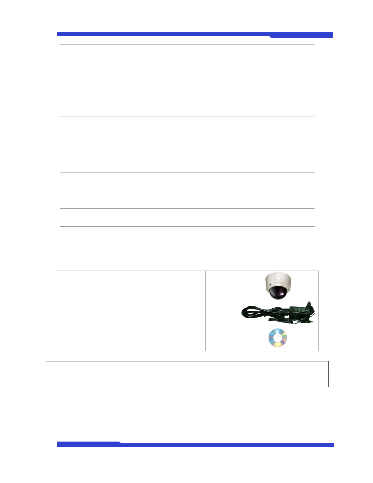
DNC IP Camera’s packing box includes the following items
IP Camera 1ea
Power Adaptor Unit
(Power Cable & DC12V, 3A Adapter)
1ea
CD (User’s Manual, installation wizard and Pictures) 1ea
Table 2 : DNC IP Camera Packing List
) Please make sure all the listed items are included in the package. For any missing items, please
contact your local distributor.
Page 8
DNC(Dmax Network Camera) User's Manual Part1
DNC 8 Dongyang Unitech Co., Ltd
2. Hardware Description
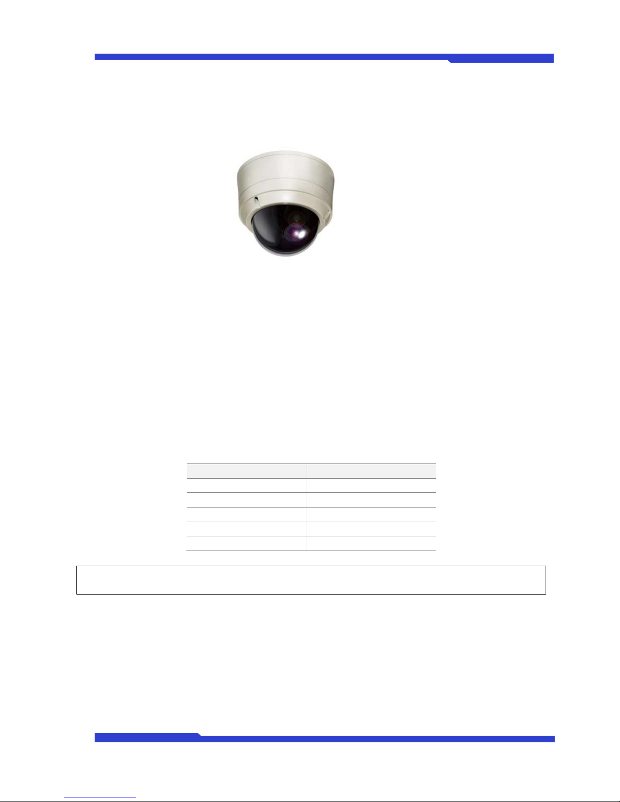
2.1. DNC IP Camera
Picture 2. DNC IP Camera with Wall Mount Bracket
3. DNC IP Camera HW installation and basic setup
3.1. Before installation
• Read User's Manual carefully
• Check User’s Network (IP Address, Network Mask and default gateway)
• Secure IP address for IP Camera.
3.2. Factory Default Condition
The table below shows the factory default conditions. Please refer to this when you need to change the
values on admin menu.
Item Factory Default
Admin ID root
Admin password root
IP address 10.20.30.40
Network mask 255.255.255.0
Gateway 10.20.30.1
Table 3 : Factory Default Condition
) Admin ID and Password are case sensitive.
Page 9

DNC(Dmax Network Camera) User's Manual Part1
DNC 9 Dongyang Unitech Co., Ltd
3.3. Hardware installation
Following pictures show the installation steps for DNC IP Camera.
1.
Next, you need to follow the steps below.
1. Network Configuration on IP-installer.
2. Camera Configuration on IP-installer or admin-menu.
3. Service Configuration on IP-installer or admin-menu.
For further details, please refer to the related part in the User’s Manual. Configuring IP Camera is mostly
done on a web browser, so users should set up the network first.
Page 10

DNC(Dmax Network Camera) User Manual Part 2
DNC 1 Dongyang Unitech Co., Ltd
DNC(Dmax Network Camera) User Manual
Part 2
(Network Configuration and DNC Setting)
Version 4.03
July 15, 2009
Dongyang Unitech Co., Ltd
www.d-max.co.kr
www.cctvhome.net
Page 11

DNC(Dmax Network Camera) User Manual Part 2
DNC 2 Dongyang Unitech Co., Ltd
TABLE
1. Network Configuration ...................................................................................................... 6
1.1. Private Network ........................................................................................................ 6
1.2. Leased Line Network ................................................................................................ 6
1.3. Cable/xDSL Modem Network with Static IP ............................................................. 7
1.4. Cable/xDSL Modem Network with Dynamic IP ........................................................ 7
1.5. PSTN Modem with Dial-out ...................................................................................... 8
1.6. PSTN Modem with Dial-in ......................................................................................... 8
2. Network Configuration ...................................................................................................... 9
2.1. Through IP Installer .................................................................................................. 9
2.1.1. What is IP Installer? .......................................................................................... 9
2.1.2. Installation of IP Installer ................................................................................. 10
2.2. How to Use IP Installer ........................................................................................... 12
2.2.1. How to Run IP Installer ................................................................................... 12
2.2.2. Program Menu Description ............................................................................. 13
2.2.3. Right Mouse Button Menu .............................................................................. 14
2.3. IP Assignment ......................................................................................................... 15
2.3.1. Diagram between DNC and PC ...................................................................... 15
2.3.2. Static IP assignment ....................................................................................... 16
2.3.3. IP Assignment through DHCP ........................................................................ 19
2.3.4.
IP Assignment by PPPoE ............................................................................... 21
2.4. Network configuration through Hyper Terminal mode ............................................ 23
2.4.1. Hyper Terminal Installation Wizard Program .................................................. 23
2.4.2. System Login and Network Configuration by Hyper Terminal ........................ 25
Page 12

DNC(Dmax Network Camera) User Manual Part 2
DNC 3 Dongyang Unitech Co., Ltd
2.4.3. RS232 Console Cable .................................................................................... 27
2.4.4. Confirmation of setup & Access to Home Page .............................................. 28
2.5. Automatic installation with UPnP ............................................................................ 29
2.5.1. Indication of installation status with Status LED ............................................. 29
2.5.2. UPnP Admin Page setup ................................................................................ 30
2.5.3. Setup following network configuration ............................................................ 32
2.6. “Home” screen server through the web browser on the PC shown as below. ..... 36
2.7. “Live View” Menu .................................................................................................... 36
2.8. “Player” Menu (NVR only) ....................................................................................... 38
2.9. “Sample” Menu ....................................................................................................... 38
2.10. “Admin” Menu ......................................................................................................... 39
Page 13

DNC(Dmax Network Camera) User Manual Part 2
DNC 4 Dongyang Unitech Co., Ltd
FIGURE CONTENTS
Figure 1 Private Network Diagram ............................................................................................ 6
Figure 2 Leased Static IP Diagram ........................................................................................... 7
Figure 3 ADSL/Cable Modem (Static IP) Diagram ................................................................... 7
Figure 4 ADSL/Cable Modem (dynamic IP) Diagram ............................................................... 8
Figure 5 Dial Out Connection (Modem) Diagram ..................................................................... 8
Figure 6 Dial in Connection (Modem) Diagram ........................................................................ 9
Figure 7 IP Installer First Installation Screen .......................................................................... 10
Figure 8 IP Installer Folder Selection ...................................................................................... 11
Figure 9 IP Installer Installation Completion ........................................................................... 12
Figure 10 IP-Installer How to Run ........................................................................................... 12
Figure 11 IP Installer Menu ..................................................................................................... 14
Figure 12 Connection through a HUB ..................................................................................... 15
Figure 13 Connection DNC to PC ........................................................................................... 15
Figure 14 In case of selecting 1 server for Static IP Assignment ........................................... 16
Figure 15 In case of selecting 2 or more servers for Static IP Assignment ............................ 17
Figure 16 In case of selecting 1 server for Automatic Static IP Assignment .......................... 19
Figure 17 In case of selecting 1 server for DHCP IP Assignment .......................................... 20
Figure 18 In case of selecting 2 or more servers for DHCP IP Assignment ........................... 21
Figure 19 In case of selecting 1 server for PPPoE IP Assignment ......................................... 22
Figure 20 Hyper Terminal Program Location .......................................................................... 23
Figure 21 COM Port Connection Description ......................................................................... 24
Figure 22 COM Port Connect To Information ......................................................................... 24
Page 14

DNC(Dmax Network Camera) User Manual Part 2
DNC 5 Dongyang Unitech Co., Ltd
Figure 23 COM Port Settings .................................................................................................. 25
Figure 24 RS232 Cross Cable ................................................................................................ 27
Figure 25 RS232 Converter Cable .......................................................................................... 28
Figure 26 Main page of DNC .................................................................................................. 36
Figure 27 Screen of DNC Live View ....................................................................................... 37
Figure 28 Player ...................................................................................................................... 38
Figure 29 Sample .................................................................................................................... 39
Page 15
DNC(Dmax Network Camera) User Manual Part 2
DNC 6 Dongyang Unitech Co., Ltd
1. Network Configuration
DNC® products work under IP network such as leased line, cable model, xDSL modem, PSTN
modem. DNC can also work under public network or private network. The network environment will
vary with users’ goals and needs; however, basic applications with DNC® products can be followings.
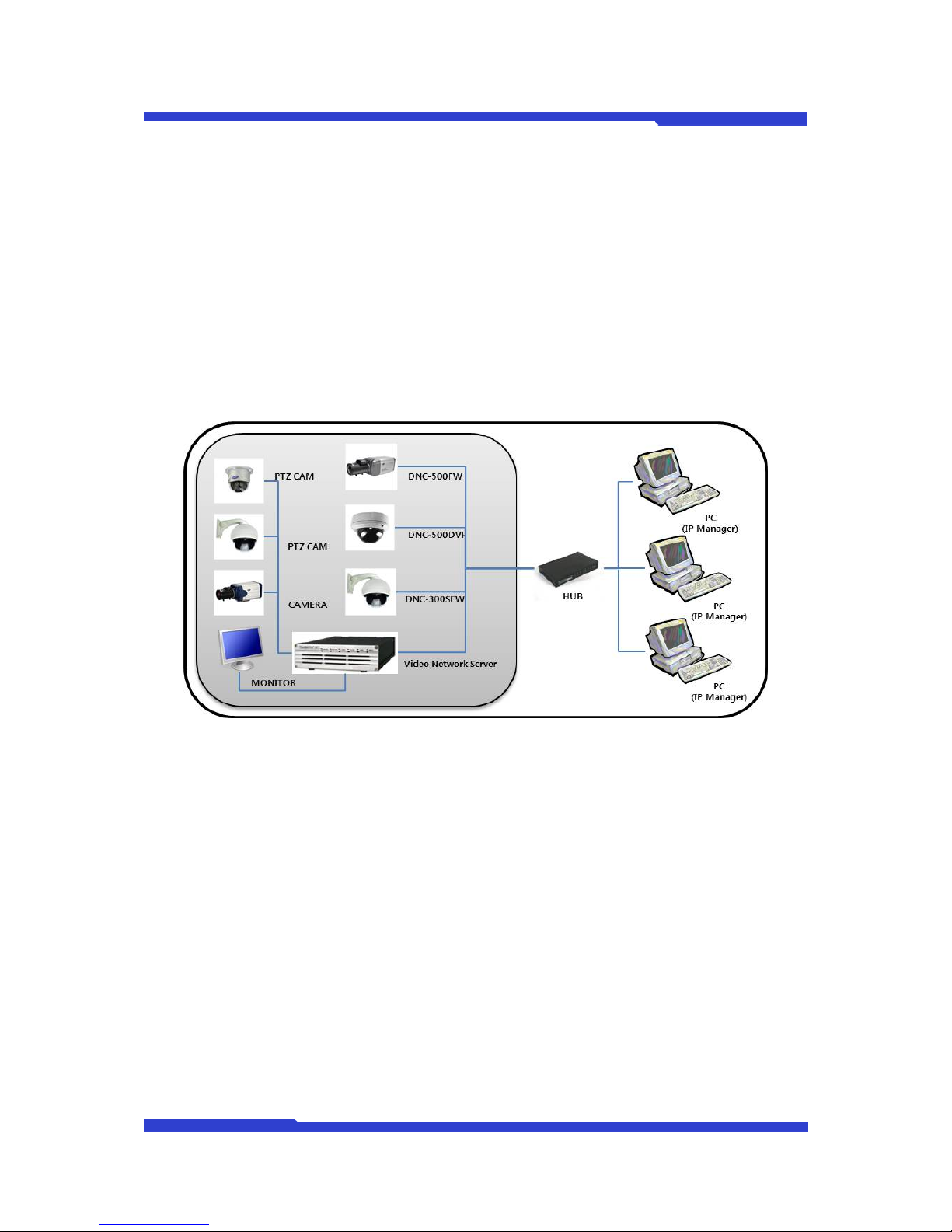
1.1. Private Network
Private network without Internet connection.
Figure 1 Private Network Diagram
1.2. Leased Line Network
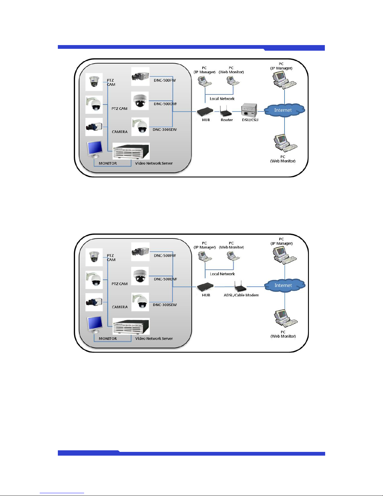
In case of leased line, most users use Public static IP, they assign public static IP to DNC server
and they can view the images from DNC locally or remotely via Internet.
Page 16
DNC(Dmax Network Camera) User Manual Part 2
DNC 7 Dongyang Unitech Co., Ltd
Figure 2 Leased Static IP Diagram
1.3. Cable/xDSL Modem Network with Static IP
You can use Static IP through cable/xDSL modem to view the images from DNC.
Figure 3 ADSL/Cable Modem (Static IP) Diagram
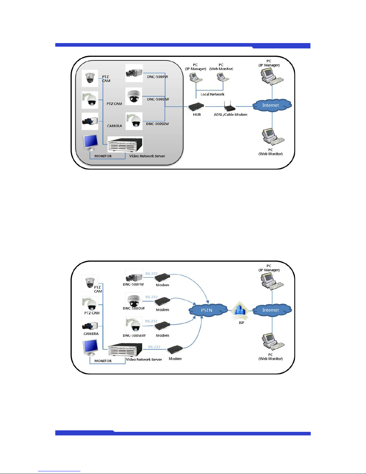
1.4. Cable/xDSL Modem Network with Dynamic IP
You can use Dynamic IP through cable/xDSL modem to view the images from DNC. In this case,
you need to register for AOIP service provided by Dongyang Unitech.
Page 17
DNC(Dmax Network Camera) User Manual Part 2
DNC 8 Dongyang Unitech Co., Ltd
Figure 4 ADSL/Cable Modem (dynamic IP) Diagram
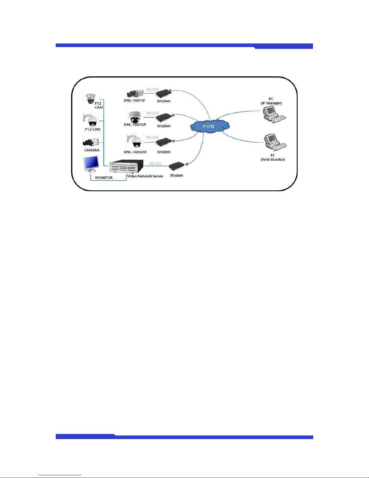
1.5. PSTN Modem with Dial-out
You can use PSTN modem to have DNC server connected to the Internet. DNC makes a call to
ISP (Dial-out) and gets connected to the Internet. In this case, the assigned IP by ISP is Public
Dynamic IP. Thus, you can view the images from DNC servers by AOIP service provided by
Dongyang Unitech.
Figure 5 Dial Out Connection (Modem) Diagram
1.6. PSTN Modem with Dial-in
You have DNC server connected to PSTN modem and remote PC can connect to this PSTN
Page 18
DNC(Dmax Network Camera) User Manual Part 2
DNC 9 Dongyang Unitech Co., Ltd
modem. Then, DNC accepts the call from remote PC (Dial-in).
Figure 6 Dial in Connection (Modem) Diagram
2. Network Configuration
The very first thing you need to do for using DNC is proper IP assignment for your DNC servers.
After this, you can go on to the next steps. There are two methods can be used. The first method is to
use DNC Installer included in CD and the other method is to use terminal emulation program (ex.
Microsoft Windows’s Hyper Terminal).
2.1. Through IP Installer
2.1.1. What is IP Installer?
IP Installer is a program which enables you to simply configure the DNC Products such as IP
setting, server and camera setting, firmware update, and so on. Please refer to IP Installer manual
included in CD-ROM provided with the product you purchased and you may want to refer to latest
available documents on our website (http://www.d-max.co.kr).
IP Installer manual has been written on the assumption that you are familiar with basic network
knowledge such as IP address, LAN, HUB, Router, and so on. For the basic network knowledge,
please refer to the related books, or you may ask your network service provider or network
administrator.
IP Installer can be used for DNC Linux series products; however, there may be some
differences based on models.
Page 19
DNC(Dmax Network Camera) User Manual Part 2
DNC 10 Dongyang Unitech Co., Ltd
2.1.2. Installation of IP Installer
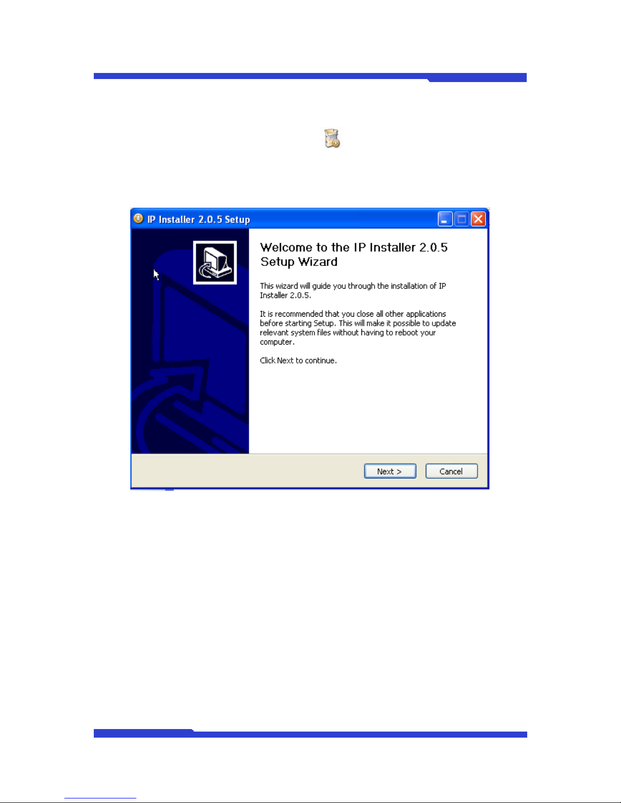
1. Please double click on the IP Installer Icon.
2. Click Next.
3. Please Check the version of IP Installer and if you want to install it, please click Next.
Figure 7 IP Installer First Installation Screen
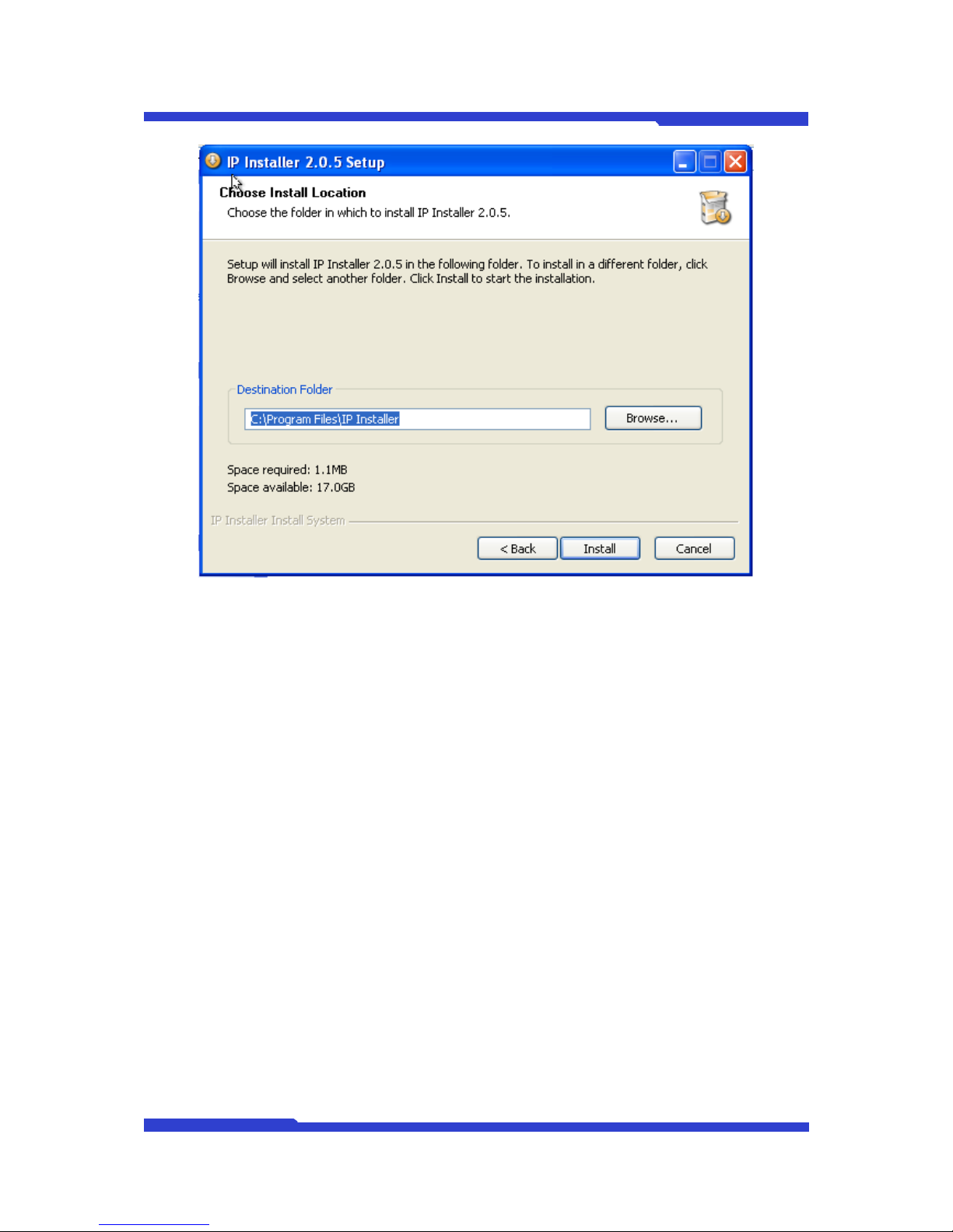
4. Select the installation location, please click Install.
The default location is C:\Program Files\IP Installer\IP Installer, and if you want to change the
location, you may click Browse and select the desired folder.
Page 20
DNC(Dmax Network Camera) User Manual Part 2
DNC 11 Dongyang Unitech Co., Ltd
Figure 8 IP Installer Folder Selection
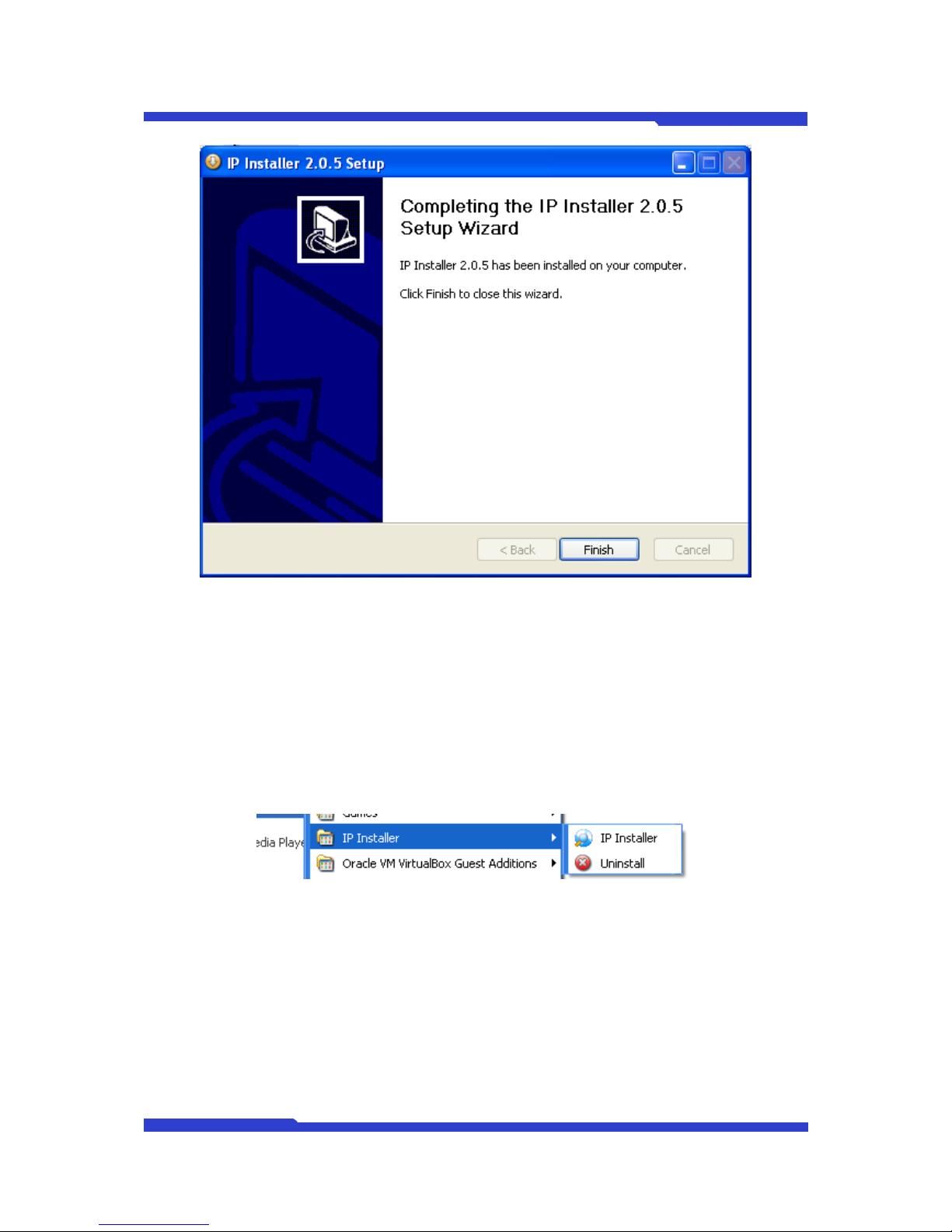
1. Click Finish (Installation Completion)
All the required files will be installed and the installation will be done by clicking Finish.
If users don’t want to use IP Installer anymore, delete the file, referring to the next chapter,
‘Deleting IP Installer’
Page 21
DNC(Dmax Network Camera) User Manual Part 2
DNC 12 Dongyang Unitech Co., Ltd
Figure 9 IP Installer Installation Completion
2.2. How to Use IP Installer
2.2.1. How to Run IP Installer
To run IP Installer, please double-click IP Installer icon in desktop screen or click the icon
located in Programs shown as below.
Figure 10 IP-Installer How to Run
Page 22
DNC(Dmax Network Camera) User Manual Part 2
DNC 13 Dongyang Unitech Co., Ltd
2.2.2. Program Menu Description
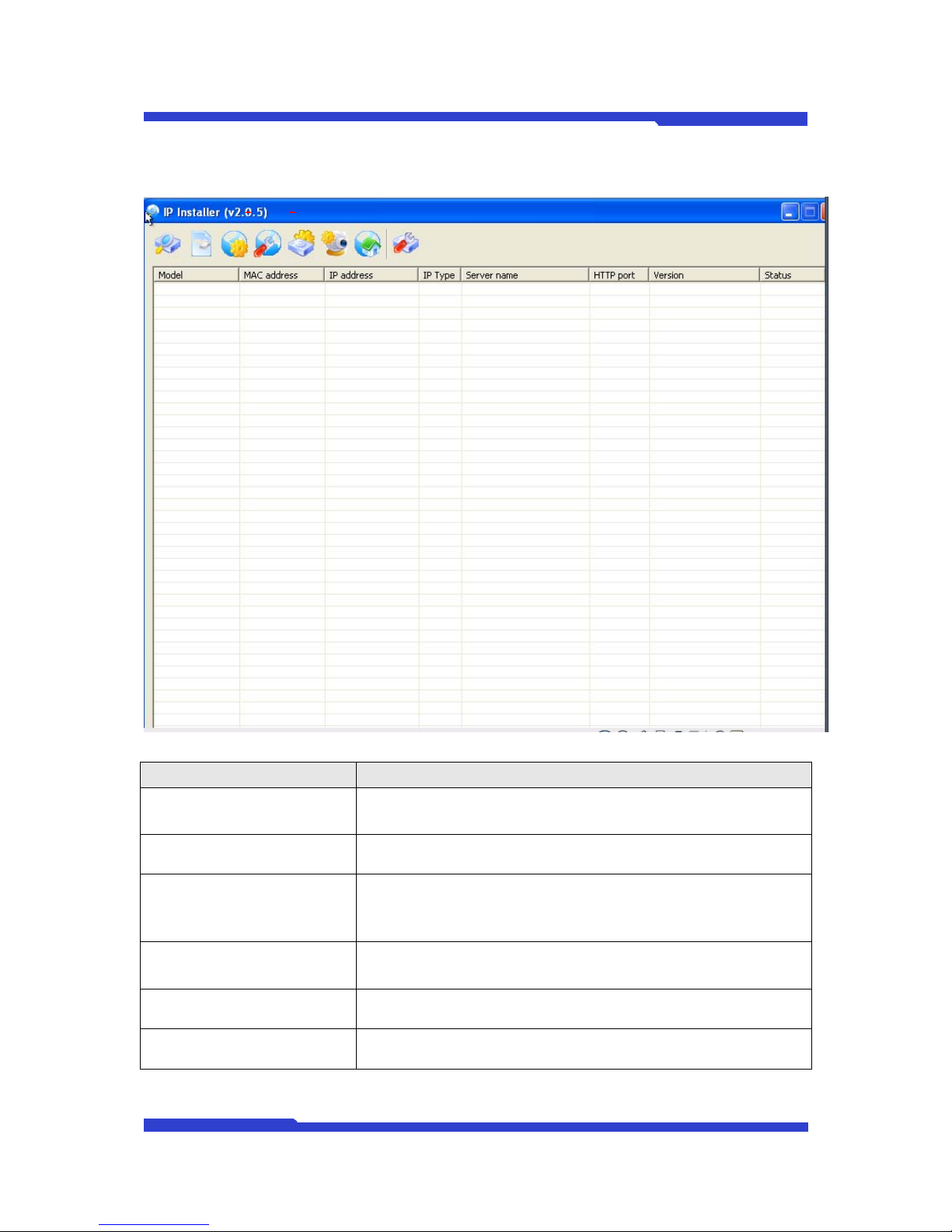
Figure 11 IP Installer’s main screen
Menu Description
Search Product
Search and show the list of DNC Linux series installed in the same
LAN of your PC.
Clear Product list Clear all the list of DNC products
Automatic IP setup
IP Installer will check the network information and you can set up IP
automatically.
TIP) IP address will be assigned automatically in descending order
after IP information is retrieved from PC.
Manual IP setup You can set up IP manually.
Server Setup Configure the DNC server.
Camera Setup Configure the DNC camera
Page 23
DNC(Dmax Network Camera) User Manual Part 2
DNC 14 Dongyang Unitech Co., Ltd
Connect Product
Connect to Homepage of selected Product
Notice) Class of IP address should be the same between PC and
DNC server.
Update firmware Update the firmware of Product.
Searched Result List Shows searched list of DNC
Total Shows the total number of searched DNC servers.
Found
Shows the total number of searched DNC servers with normal
respond
* For second try, ‘Found’ means the number of devices available for
searching normally.
Timeout
Shows the total number of DNC servers with no response on
search again.
* For second try, ‘Timeout’ means the number of normally ‘notresponding’ devices.
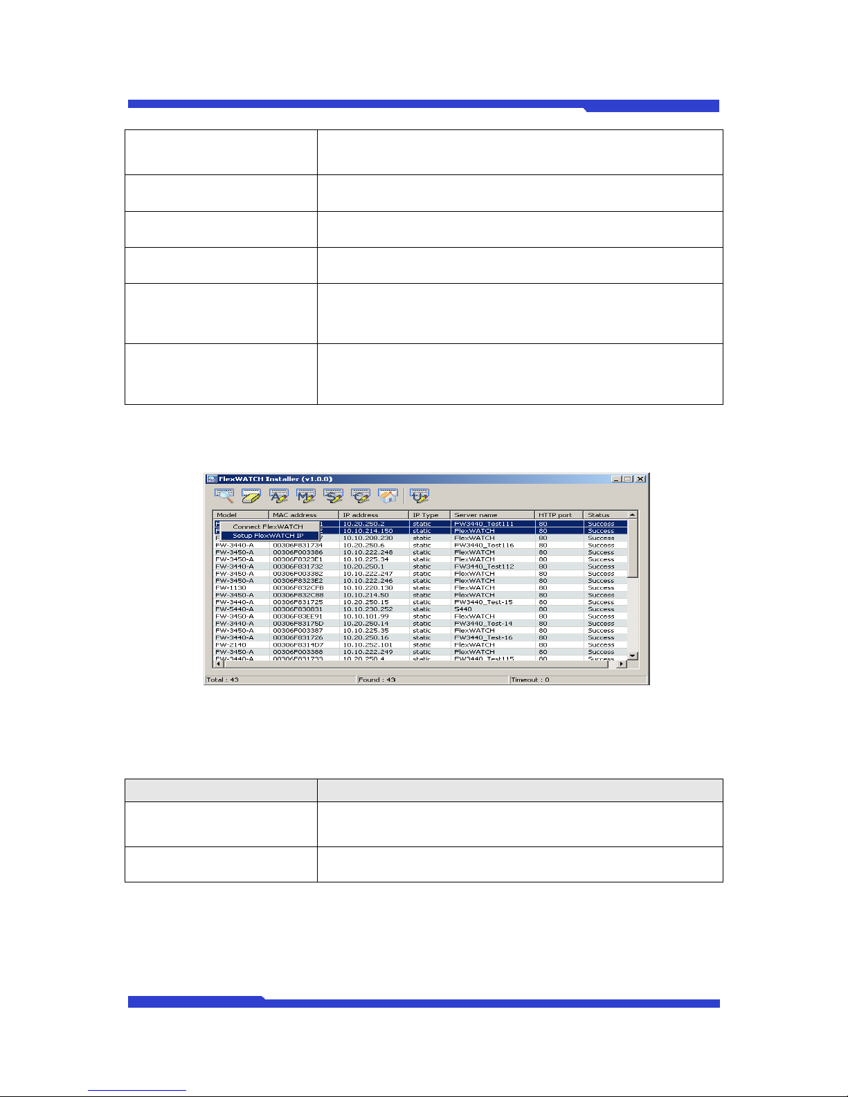
2.2.3. Right Mouse Button Menu
Figure 11 IP Installer Menu
Select one of the searched products and right click of Mouse Button for menu.
Menu Description
Connect Product
Connect to the Homepage of selected DNC server.
Notice) Class of IP address should be the same between PC and
DNC.
Setup Product IP Configure the network setting of the selected DNC server.
TIP) More information on IP setting will be further discussed in 2.3 IP assignment.
Page 24
DNC(Dmax Network Camera) User Manual Part 2
DNC 15 Dongyang Unitech Co., Ltd
2.3. IP Assignment
There are three different ways of IP setup for the network connection of your DNC server.
1. Static IP Assignment
General IP assignment method, to setup public or private static IP address.
2. IP Assignment by DHCP
IP assignment method, using DHCP to connect DNC by cable modem or VDSL.
3. IP Assignment by PPPoE
IP assignment method using PPPoE to connect DNC by xDSL.
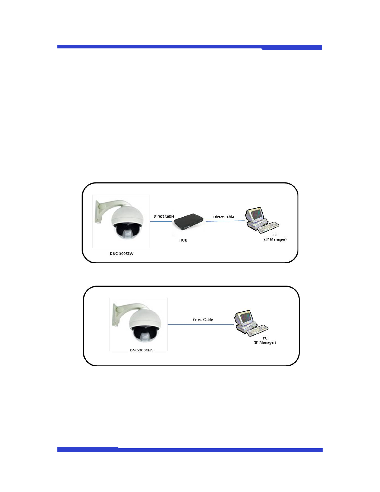
2.3.1. Diagram between DNC and PC
Figure 12 Connection through a HUB
Figure 13 Connection DNC to PC
Please use Direct Cable when you use a Hub while you use Cross-Over Cable for direct
connection between DNC and PC.
Page 25
DNC(Dmax Network Camera) User Manual Part 2
DNC 16 Dongyang Unitech Co., Ltd
2.3.2. Static IP assignment
2.3.2.1. Manual IP Assignment
There are two types of static IP including public IP or private IP in LAN with an IP sharer or a
router.
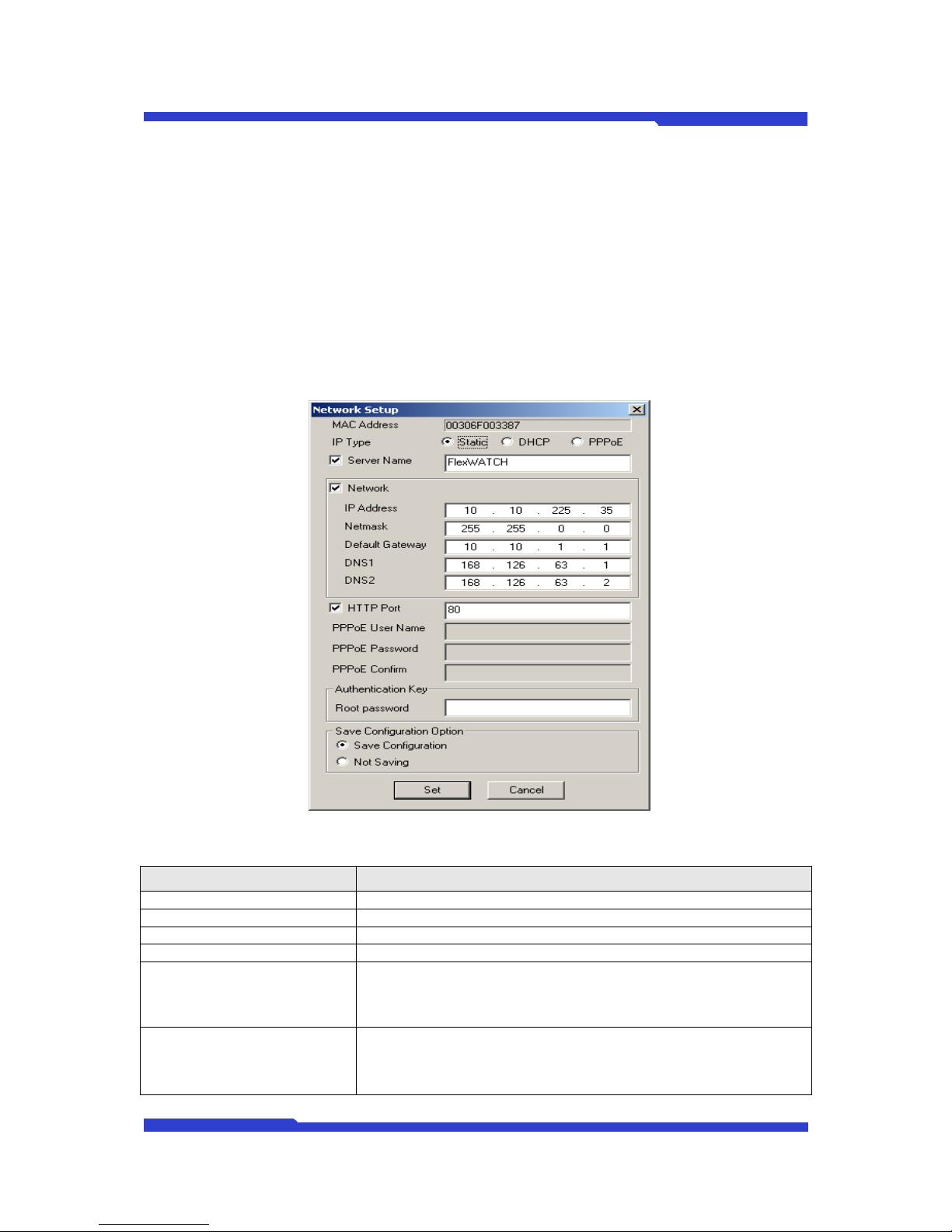
1. Please run IP Installer, and search to see available DNC servers on the list. Then,
please select the server from the list and click on IP Setup button or IP Setup from the
right mouse button menu.
z In case of selecting 1 server from the list
Figure 14 In case of selecting 1 server for Static IP Assignment
Menu Description
MAC Address MAC address of selected DNC
IP Type Please select Static for Static IP Assignment
Server Name Assign a name to selected DNC
Network Setting for the general Network Information
IP Address Enter IP address for DNC server.
Netmask
Netmask is for dividing IP classes. Please ask the network
administrator before setting.
Page 26
DNC(Dmax Network Camera) User Manual Part 2
DNC 17 Dongyang Unitech Co., Ltd
Default Gateway Default gate way will be automatically searched by IP Installer.
DNS1, DNS2
Domain Name Service is a service to transfer Text address into IP
address, KT uses ‘’168.126.63.1’ and Drunet uses ‘210.117.65.1’.
HTTP Port Default web port for DNC. Default value is 80.
Root password
Password for DNC server to authenticate a valid user. The default
password for DNC is root.
Save Configuration Option It makes set items save.
Save Configuration All the changes will be stored in Flash Memory.
Not Saving
All the changes will not be stored in Flash Memory.
Notice) If you choose “Not Saving”, all the adjusted settings will not
be saved, Therefore, after rebooting, new change won’t be applied.
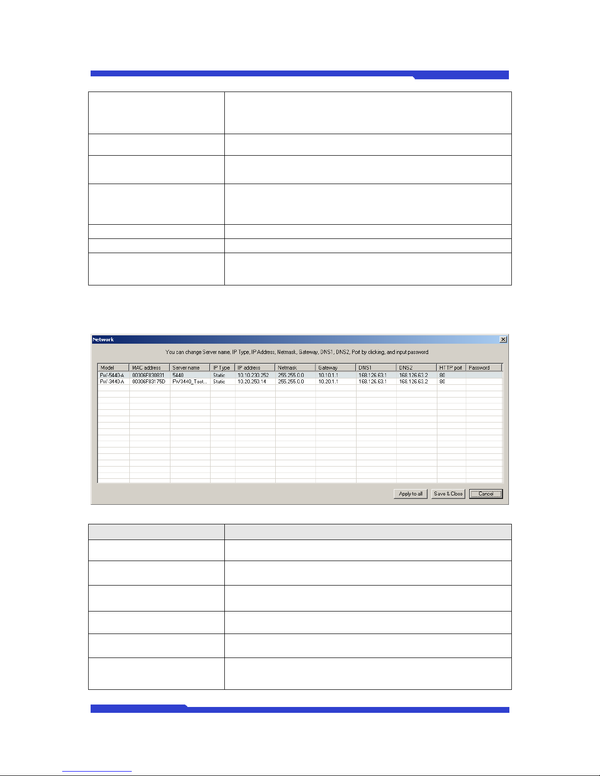
z In case of selecting 2 or more servers from the list
Figure 15 In case of selecting 2 or more servers for Static IP Assignment
Menu Description
Model Model name of selected DNC.
MAC address MAC address of selected DNC
Server name Assign a name to selected DNC
IP Type Please select Static for Static IP Assignment
IP address Enter proper IP address for DNC server
Netmask
A Netmask is used to divide an IP address into subnets and specify
the network available hosts. Contact your network administrator for
more details.
Page 27

DNC(Dmax Network Camera) User Manual Part 2
DNC 18 Dongyang Unitech Co., Ltd
Gateway Default gateway will be automatically searched by IP Installer.
DNS1, DNS2
Domain Name Service is a service to transfer Text address into IP
address, KT uses ‘’168.126.63.1’ and Drunet uses ‘210.117.65.1’.
HTTP port Default web port for DNC. Default value is 80.
Password
Password for DNC server to authenticate a valid user. The default
password for DNC is root.
Apply to all
Please use this button when you enter the same values for multiple
servers. Please click one of the listed servers and make changes
as you wish. The values of rest of FW servers will be changed
accordingly. However, server names will be in the format of “your
chosen server name”+ascending number. And IP address will be
also assigned automatically by adding 1.
Save & Close
Will save all the changes to DNC servers and close network setting
window. (All the adjusted settings will be stored in Flash Memory)
Cancel
Cancel the all the adjusted setting and close the network setting
window.
2. After IP configuration, click “Connect” icon to access DNC. See live view of DNC or
specify system configuration on admin menu. Please refer to chapter 3.2 Live View and
“User Manual for DNC” for more details of system configuration and live view.
2.3.2.2. Automatic IP Assignment
IP Installer can automatically find available IP address from the network in which IP Installer is
being used. You can use the IP address searched by IP Installer or you may change the IP by yourself.
Notice) Since IP devices online is searched only, any of the auto-assigned IP may cause a
network collision and problem if the status of IP devices offline turns into online (in case of Power-On
or new IP configuration) in the same network., so Auto-assigned IP is assigned based on C-Class or
its Subnet.
1. Please run IP Installer, and search to see available DNC servers on the list. Then,
please select the server from the list and click on Automatic IP Setup button.
z In case of selecting 1 server from the list
Page 28
DNC(Dmax Network Camera) User Manual Part 2
DNC 19 Dongyang Unitech Co., Ltd
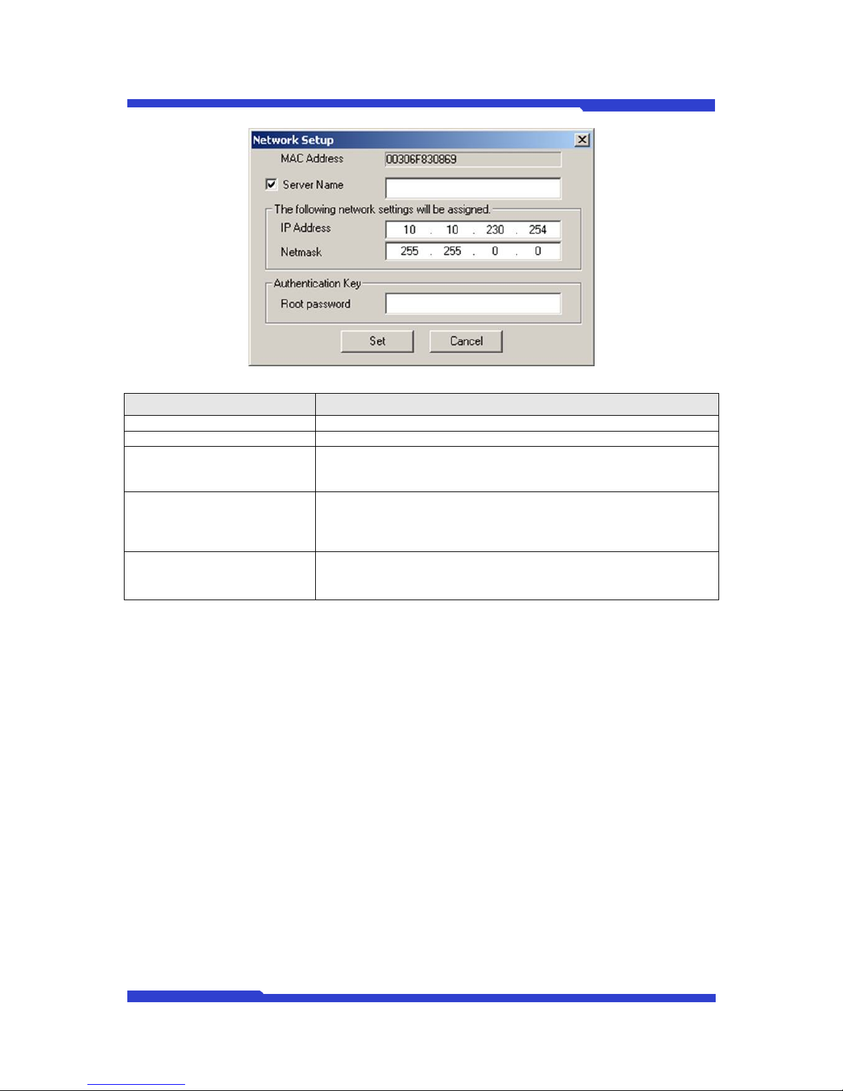
Figure 16 In case of selecting 1 server for Automatic Static IP Assignment
Menu Description
Server Name Assign a name to selected DNC
Network Setting for the general Network Information
IP Address
Automatic assigned IP will be shown. You may use or change it.
Notice) In case of IP conflict, you shall assign proper IP to DNC
server.
Netmask
Automatic assigned Netmask will be shown. You may use or
change it.
Netmask is for dividing IP classes. Please ask the network
administrator for more info.
Root password
Password for DNC server to authenticate a valid user. The default
password for DNC is root.
z In case of selecting 2 or more servers from the list
TIP) Please refer to 2.3.2.1 Manual IP Assignment
2.3.3. IP Assignment through DHCP
When your local network is managed by DHCP server, cable modem, or VDSL, DHCP IP
Assignment is used. xDSL with auto-dial up also needs DHCP IP Assignment.
1. Connect your PC and DNC server in the network. Setup a static IP address according
to the steps in chapter ‘2.2. How to use IP Installer’.
2. Click ‘Connect’ icon to access to DNC after IP setup is completed.
Set up systems either by looking at videos of DNC or using Admin Menu.
To know ‘looking at videos’, refer to ‘2.6. How to see DNC video’ and to know how to
set up systems, refer to DNC user manual.
TIP) To access to DNC remotely, be sure to st up AOIP in Admin Menu.
3. Choose the device to set up after searching with IP Installer. Then, click ‘IP Setup’
menu through IP setup button or right click and change setup to DHCP.
Page 29
DNC(Dmax Network Camera) User Manual Part 2
DNC 20 Dongyang Unitech Co., Ltd
z In case of selecting 1 server from the list
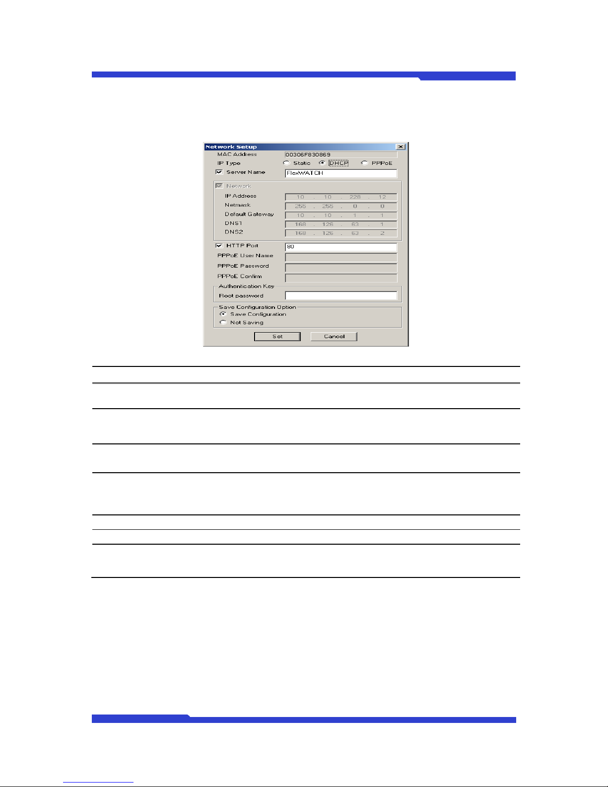
Figure 17 In case of selecting 1 server for DHCP IP Assignment
Menu Description
IP Type Select ‘DHCP’
Server Name Assign a name to selected DNC
HTTP Port Default web port for DNC. Default value is 80.
Root password
Password for DNC server to authenticate a valid user. The default
password for DNC is root.
Save Configuration Option Menu to save set items.
Save Configuration All the changes will be stored in Flash Memory..
Not Saving
All the changes will not be stored in Flash Memory.
Notice) If you choose “Not Saving”, all the adjusted settings will not
be saved, Therefore, after rebooting, new change won’t be applied.
z In case of selecting 2 or more servers for DHCP IP Assignment
Page 30
DNC(Dmax Network Camera) User Manual Part 2
DNC 21 Dongyang Unitech Co., Ltd
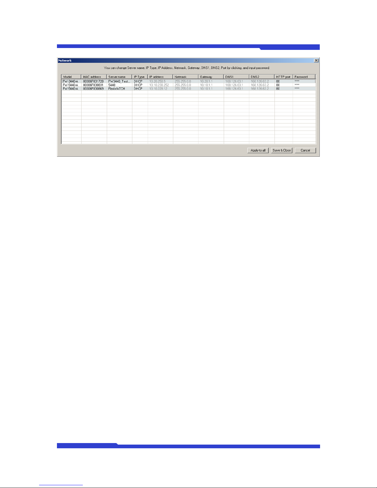
Figure 18 In case of selecting 2 or more servers for DHCP IP Assignment
TIP) In case of multiple DHCP settings, you can’t set IP address, Netmask, Gateway, DNS1, 2.
Please refer to Static Manual IP Assignment.
4. Check out if your DHCP setup is correctly applied; please connect DNC to VDSL or
Cable Modem. If your server is under Local network, please connect DNC to a HUB in
Local Network.
2.3.4. IP Assignment by PPPoE
1. Assign static IP of DNC in same the class with PC. Or it’s easy to setup IP assignment
in reference to ‘2.2. How to use IP Installer’.
2. After IP setup, check out if you can access to the homepage of DNC server by clicking
“Connect” icon. Set up systems by looking at videos of DNC or using Admin Menu.
Refer to ‘2.6. Admin Page of DNC in relation to looking at videos, DNC user manual for
system configuration.
Notice) Make sure to set up AOIP to remotely access to DNC.
3. Run IP Installer again, and select DNC on the search list, Click IP Setup button and
specify PPPoE option.
Page 31
DNC(Dmax Network Camera) User Manual Part 2
DNC 22 Dongyang Unitech Co., Ltd
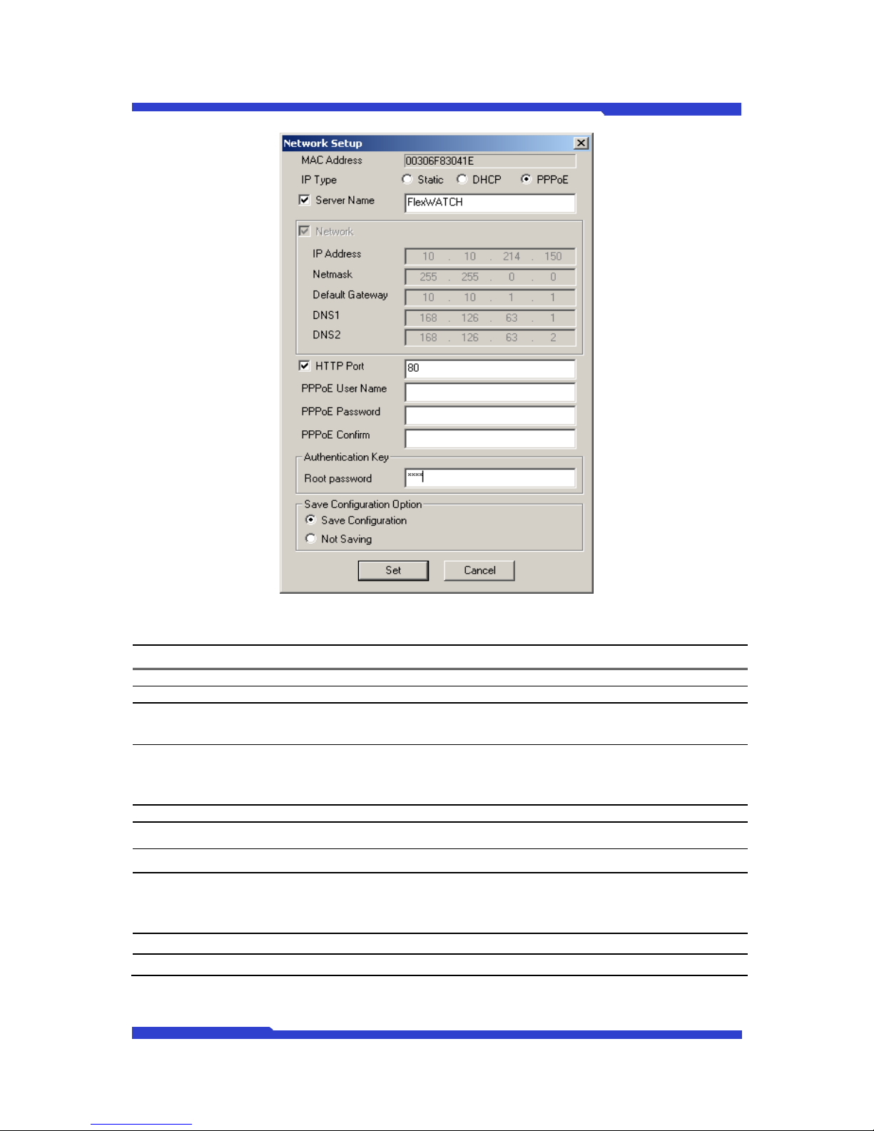
Figure 19 In case of selecting 1 server for PPPoE IP Assignment
Menu Description
IP Type Select ‘PPPoE’
Server Name Assign a name to selected DNC
HTTP Port Default web port for DNC. Default value is 80.
PPPoE setup
Type ID/Password through PPPoE.
Notice) You can check out the correct ID/Password from your ISP.
PPPoE User Name Enter PPPoE ID
PPPoE Password Enter PPPoE Password
PPPoE Confirm Enter PPPoE Confirmed Password
Password
Password for DNC server to authenticate a valid user. The default
password for DNC is root.
Save Configuration Option Save set items.
Save Configuration All the changes will be stored in Flash Memory.
Page 32
DNC(Dmax Network Camera) User Manual Part 2
DNC 23 Dongyang Unitech Co., Ltd
Not Saving
All the changes will not be stored in Flash Memory.
Notice) If you choose “Not Saving”, all the adjusted settings will not
be saved, Therefore, after rebooting, new change won’t be applied.
4. Check out if your PPPoE setup is correctly applied; please connect DNC directly to
xDSL modem.
Notice) Choose one device only for PPPoE setup. In case of selection more than 2 devices,
PPPoE setup is not supported.
2.4. Network configuration through Hyper Terminal mode
Microsoft Windows provides Terminal emulation program, named Hyper Terminal.
It is a method to set up network with console after login. For doing that, to connect COM port of
DNC® with Serial port (COM1 or COM2) of user’s PC with serial cable provided.
You can continue below configuration after Network setting, and the next process will be same
as using Installation Wizard Program.
2.4.1. Hyper Terminal Installation Wizard Program
1. Link up with the provided serial cable between COM port at DNC server and COM1 or
COM2 at user’s PC.
2. Run Hyper Terminal Program on user’s PC.
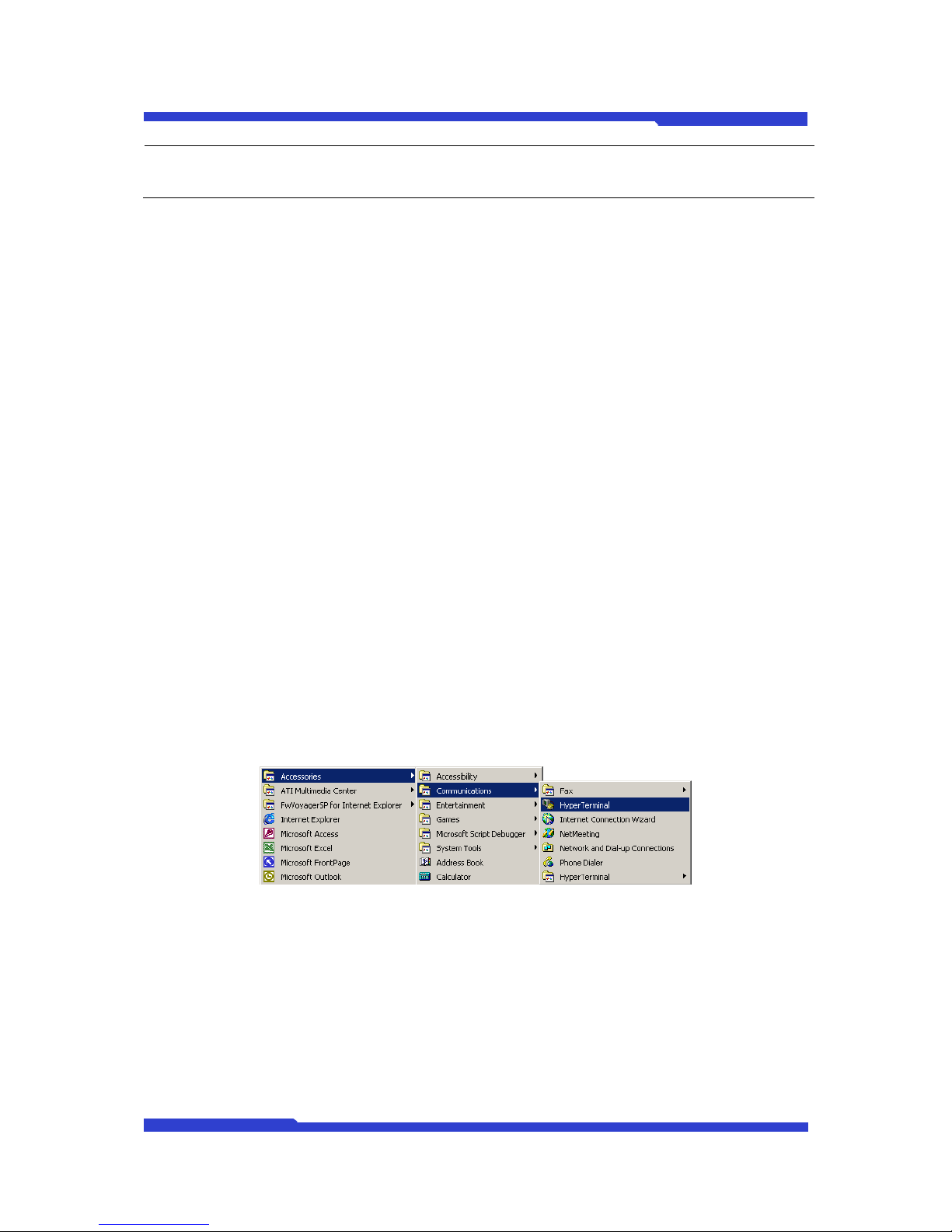
Window start
Æ
All ProgramsÆ Accessories Æ Communications Æ Hyper
Terminal
Figure 20 Hyper Terminal Program Location
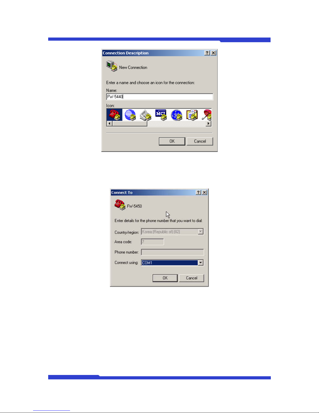
3. If Hyper Terminal window come up as below, input HyperTerminal name (ex. dmax)
and press ‘OK’ button.
Page 33
DNC(Dmax Network Camera) User Manual Part 2
DNC 24 Dongyang Unitech Co., Ltd
Figure 21 COM Port Connection Description
4. Select the connected COM port with serial cable and press OK button.
Figure 22 COM Port Connect To Information
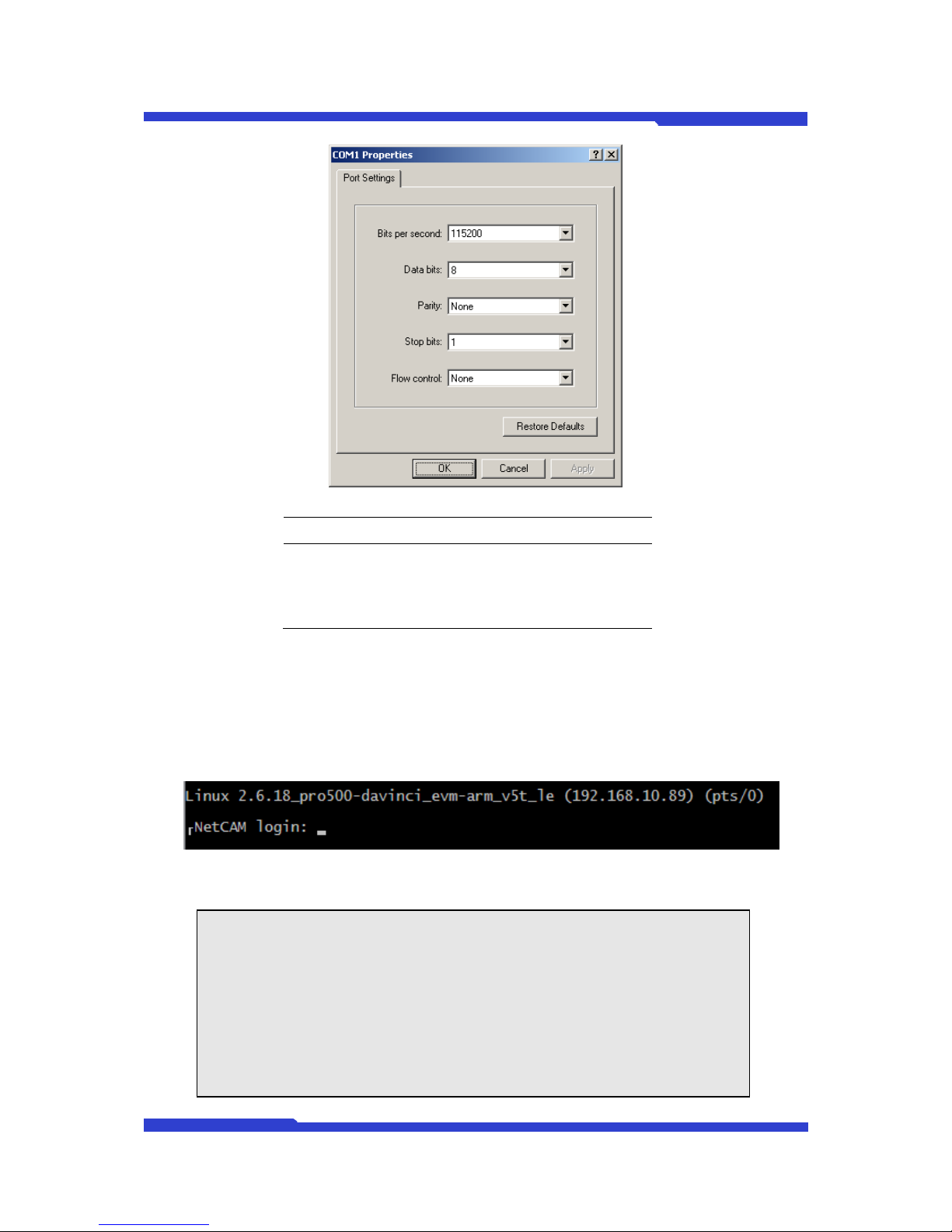
5. When ‘Port Settings’ window shows up, input each values from the table below.
Page 34
DNC(Dmax Network Camera) User Manual Part 2
DNC 25 Dongyang Unitech Co., Ltd
Figure 23 COM Port Settings
Serial Port Settings Value
Bits per Second 115200
Data bits 8
Parity None
Stop bits 1
Flow control None
2.4.2. System Login and Network Configuration by Hyper Terminal
1. After setting Hyper Terminal, press Enter key several times and then you can see
messages below. Enter Login ID and Password. (Factory defaults for Admin ID and
Password is root/root.)
2. If you correctly enter ID and Password, ‘bash#’ prompt will show up as below.
NetCAM login: root
Password: root
----------------------------------------------------------VERSION : 3.0.070327-mpeg
MODEL : DNC-500DVF
-----------------------------------------------------------
login[504]: root login on `ttyS0'
bash#
Page 35

DNC(Dmax Network Camera) User Manual Part 2
DNC 26 Dongyang Unitech Co., Ltd
3. ‘Input ‘netconfig eth1 IP, SubnetMask, Gateway’, and press Enter key as below.
e.g.) bash# netconfig eth1 192.168.0.253 255.255.255.0 192.168.0.1
bash# netconfig eth0 192.168.0.253
255.255.255.0 192.168.0.1
Your network configuration was changed.
Shutting down interface ppp2 [ OK ]
Shutting down interface ppp1 [ OK ]
Shutting down interface eth1 [ OK ]
Shutting down interface eth0 [ OK ]
Disabling IPv4 packet forwarding [ OK ]
Setting network parameters [ OK ]
Bringing up interface lo [ OK ]
Bringing up interface eth0 [ OK ]
Bringing up interface eth1 [ OK ]
Bringing up interface ppp1 [ OK ]
Your new network configuration was applied.
bash#
1. IP setup will not be completed until IP, subnet mask, gateway is saved to flash memory
when bash# prompt is displayed.
2. Type ‘savecfg’ and click ‘Enter’. Then, below message shows and figures can be
changed. Check ‘[OK] message below.
3. Type ‘reboot’ and click ‘Enter’ once changed setup is saved, bash# prompt is displayed.
bash#
bash# savecfg
Saving a current config to flash memory
[ OK ]
Updated flash
bash#
bash#
bash# reboot
Broadcast message from root (ttyp0) Mon Sep 6 19:28:51 2004...
The system is going down for reboot NOW!!
bash#
4. To check whether your Network configuration is correctly applied or not, press ‘ifconfig’
command, then following messages will show up. On the second line of the ‘eth1’
message, if the values are different from what you want to set-up, try again the
Network configuration from step H.
Page 36
DNC(Dmax Network Camera) User Manual Part 2
DNC 27 Dongyang Unitech Co., Ltd
Bash# ifconfig
eth0 Link encap:Ethernet HWaddr 00:30:6F:48:64:86
inet addr:10.20.30.40 Bcast:10.20.30.255
Mask:255.255.255.0
UP BROADCAST RUNNING MULTICAST MTU:1500 Metric:1
RX packets:0 errors:0 dropped:0 overruns:0 frame:0
TX packets:0 errors:0 dropped:0 overruns:0 carrier:0
collisions:0 txqueuelen:100
Interrupt:9
eth1 Link encap:Ethernet HWaddr 00:30:6F:48:E4:86
inet addr:192.168.0.253 Bcast:10.255.255.255
Mask:255.255.255.0
UP BROADCAST RUNNING MULTICAST MTU:1500 Metric:1
RX packets:1453 errors:0 dropped:0 overruns:0 frame:0
TX packets:62 errors:0 dropped:0 overruns:0 carrier:0
collisions:0 txqueuelen:100
Interrupt:10 Base address:0x2100
lo Link encap:Local Loopback
inet addr:127.0.0.1 Mask:255.0.0.0
UP LOOPBACK RUNNING MTU:16436 Metric:1
RX packets:309 errors:0 dropped:0 overruns:0 frame:0
TX packets:309 errors:0 dropped:0 overruns:0 carrier:0
collisions:0 txqueuelen:0
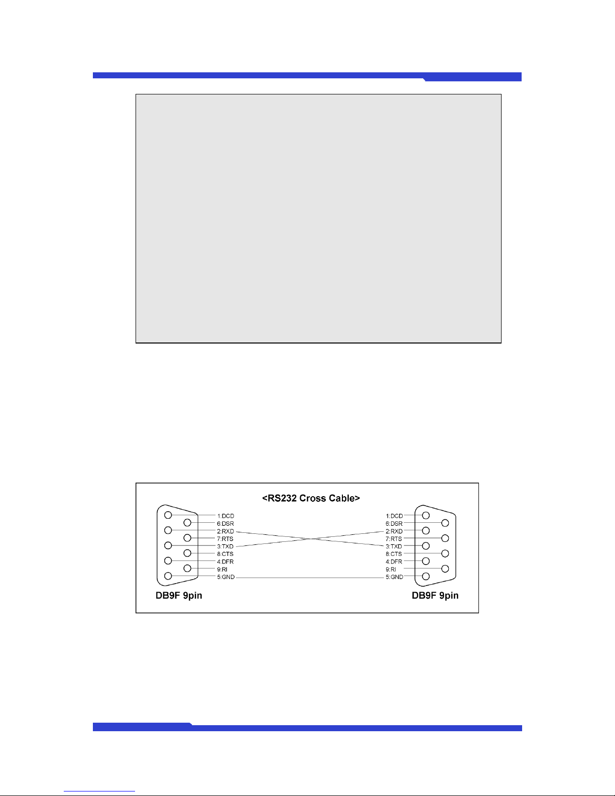
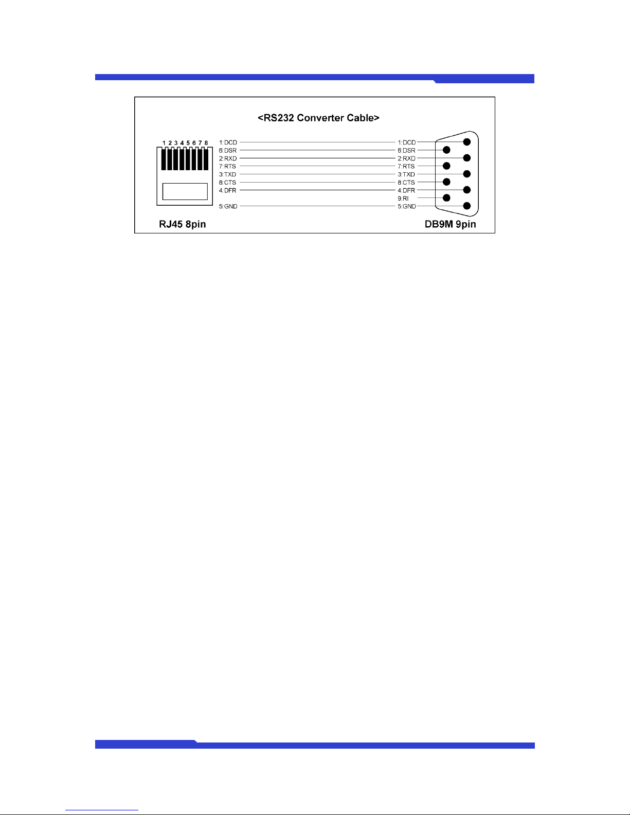
2.4.3. RS232 Console Cable
Cable used for RS232 Console Cable can be made with a combination of RS232 Cross Cable
and RS232 Converter Cable
2.4.3.1. RS232 Cross Cable
RS232 Console Cable is DNC’s Console Cable made of DB9 Connecto r, it can be used
properly.
Figure 24 RS232 Cross Cable
2.4.3.2. RS232 Converter Cable
RS232 Converter Cable can be used as DNC’s Console Cable made of RJ45 Connector after
linking with RS232 Console Cable.
Page 37
DNC(Dmax Network Camera) User Manual Part 2
DNC 28 Dongyang Unitech Co., Ltd
Figure 25 RS232 Converter Cable
In connection to Modem, RS232 Converter Cable can be linked to Modem Cable.
2.4.4. Confirmation of setup & Access to Home Page
Open Internet Explorer, type IP address to access to DNC.
Page 38

DNC(Dmax Network Camera) User Manual Part 2
DNC 29 Dongyang Unitech Co., Ltd
2.5. Automatic installation with UPnP
UPnP (Universal Plug and Play) has been developed to provide easy, convenient
communication method between separated devices & services such as information / wireless
communication / PC devices.
UPnP is standardized method without user work in network environment where administrator is
not available such as home or small office, provides communication between devices or devices and
internet.
UPnP function of DNC is for providing easy installation environment for users by executing port
mapping after searching for router to support UPnP.
Users can configure network so that access to DNC would be possible without port mapping of
router, IP installed can be used liking to (Always On IP) Service.
2.5.1. Indication of installation status with Status LED
DNC notifies users of current status of installation with Status LED.
Users need to take actions depending on installation status by Status LED.
1. OFF: IP unconfirmed
2. Repetitive ON/OFF every 1 sec: IP confirmed, internet unconfirmed.
3. Repetitive ON/OFF every 1/4 sec: internet confirmed, Port mapping unconfirmed.
4. Repetitive ON/OFF every 1/16 sec: Port mapping completed, no response from AOIP
server AOIP
5. ON: test completed in AOIP server, integrity of DNC checked every 1 hour.
In case access to DNC fails, take installation steps, going back to 1 stage.
Page 39
DNC(Dmax Network Camera) User Manual Part 2
DNC 30 Dongyang Unitech Co., Ltd
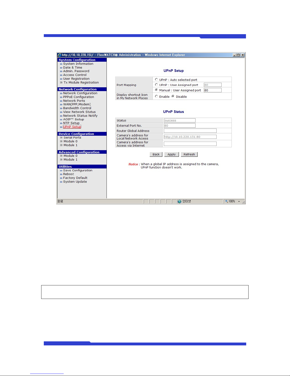
2.5.2. UPnP Admin Page setup
z Port mapping -> UPnP Auto Selected Port
Router to support UPnP function executes port mapping automatically by request, result is
displayed in UPnP status. External Port number is automatically assigned.
z Port mapping -> UPnP User Assigned Port
Router to support UPnP fuction executes Port mapping with the assigned Port Number,
result is displayed in UPnP Status.
In case other device uses same Port Number, result is shown as ‘Fail’.
) Be sure to type port number.
z Port mapping -> Manual User Assigned Port
UPnP Port mapping is not executed. It is used when port mapping is not necessary or users
Page 40

DNC(Dmax Network Camera) User Manual Part 2
DNC 31 Dongyang Unitech Co., Ltd
tries to do port mapping of router manually.
) Be sure to type port number.
z Display Shortcut Icon in My Network Places
DNC is displayed in users’ network places.
It is required to activate this function with additional OS setup in Windows XP.
) How to activate UPnP function in Windows XP
1. Control Panel -> Click ‘Add/Remove programs’
2. Click ‘Add/Remove Windows Components in the left.
3. Click ‘Networking service’ in pop-up.
4. Make UPnP user interface ‘Enable’ and click ‘OK’.
5. Pop-up disappears, click ‘Next’.
6. This function is ‘Enable’ as default in Windows Vista.
) IP class of PC should correspond to that of DNC.
) Windows setting in Windows XP is needed although DNC is displayed in ‘My Network Places’.
) DNC is not shown in other applications not Windows VISTA, Windows XP.
z UPnP Status
Overall operation status of UPnP such as external IP of router, Port Number of Port
mapping, internal IP address is displayed
z Refresh Button
UPnP Status is refreshed. Use this button when status is not refreshed after some cases
like ‘Apply’.
z Apply
Setup is applied. Current Installation steps are checked and are displayed with LED after
Status LED is turned off.
One hour takes for DNC to sense this when network environment is changed.
Page 41
DNC(Dmax Network Camera) User Manual Part 2
DNC 32 Dongyang Unitech Co., Ltd
So users can use this when users want to proceed with the all the operation tests without
waiting for the time needed.
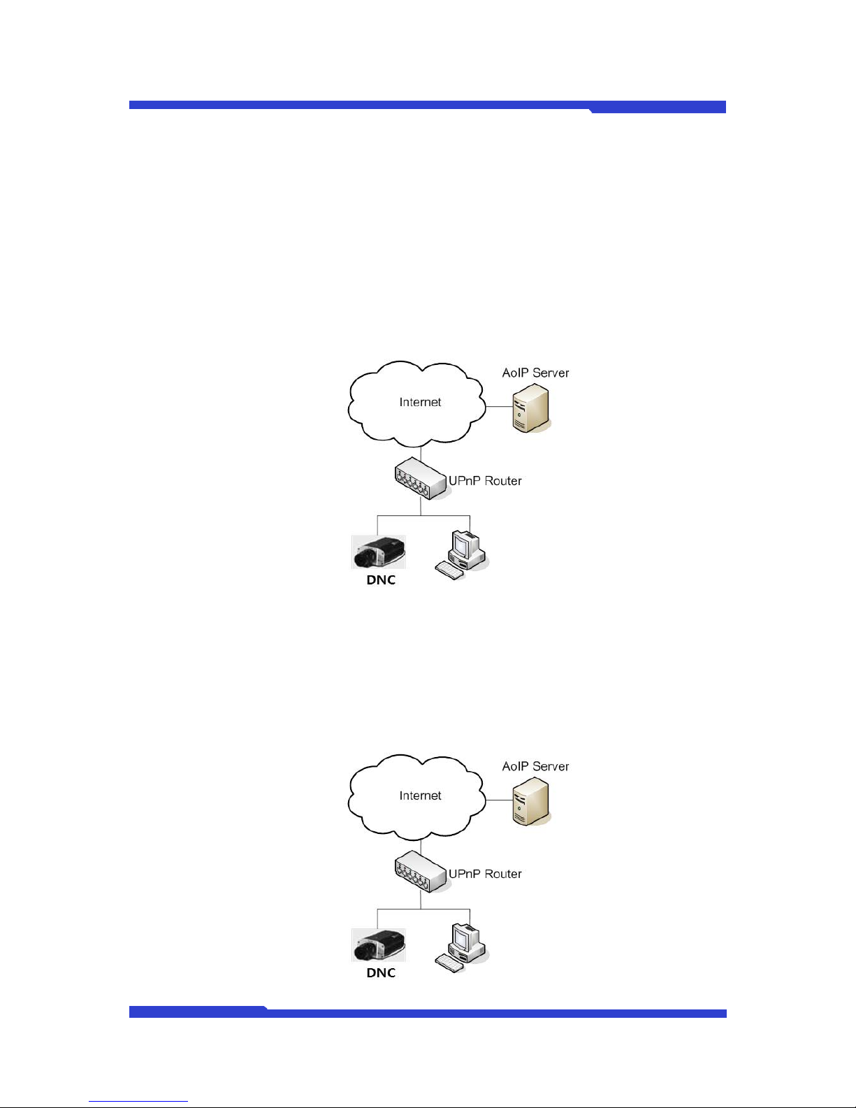
2.5.3. Setup following network configuration
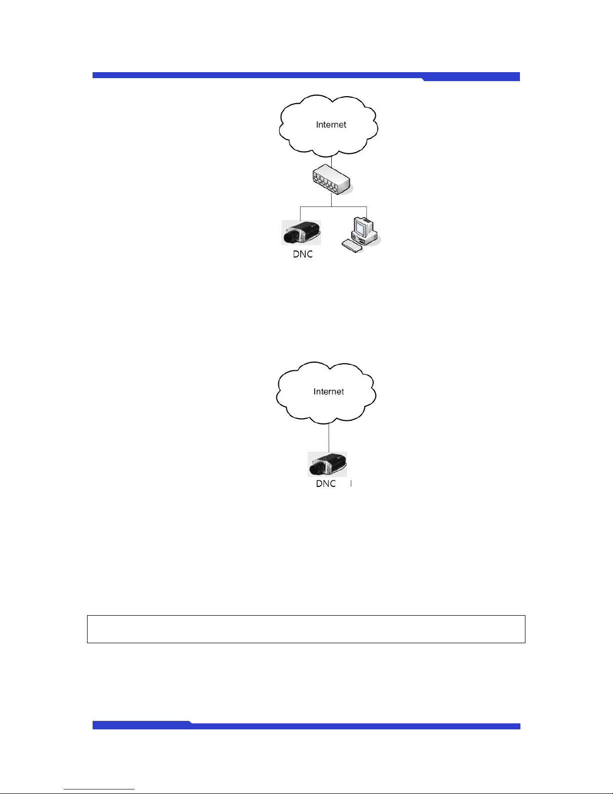
2.5.3.1. When IP sharer to support UPnP Port mapping is installed in DNC and
registration to AOIP server is needed
A. UPnP Port mapping : UPnP-Auto or UPnP-User Assigned
B. AOIP Setting: Enable.
2.5.3.2. When IP sharer to support UPnP Port mapping is installed in DNC and
registration to AOIP server is NOT needed
2.5.3.3.
C. UPnP Port mapping : UPnP-Auto or UPnP-User Assigned
D. AOIP Setting: Disable.
Page 42
DNC(Dmax Network Camera) User Manual Part 2
DNC 33 Dongyang Unitech Co., Ltd
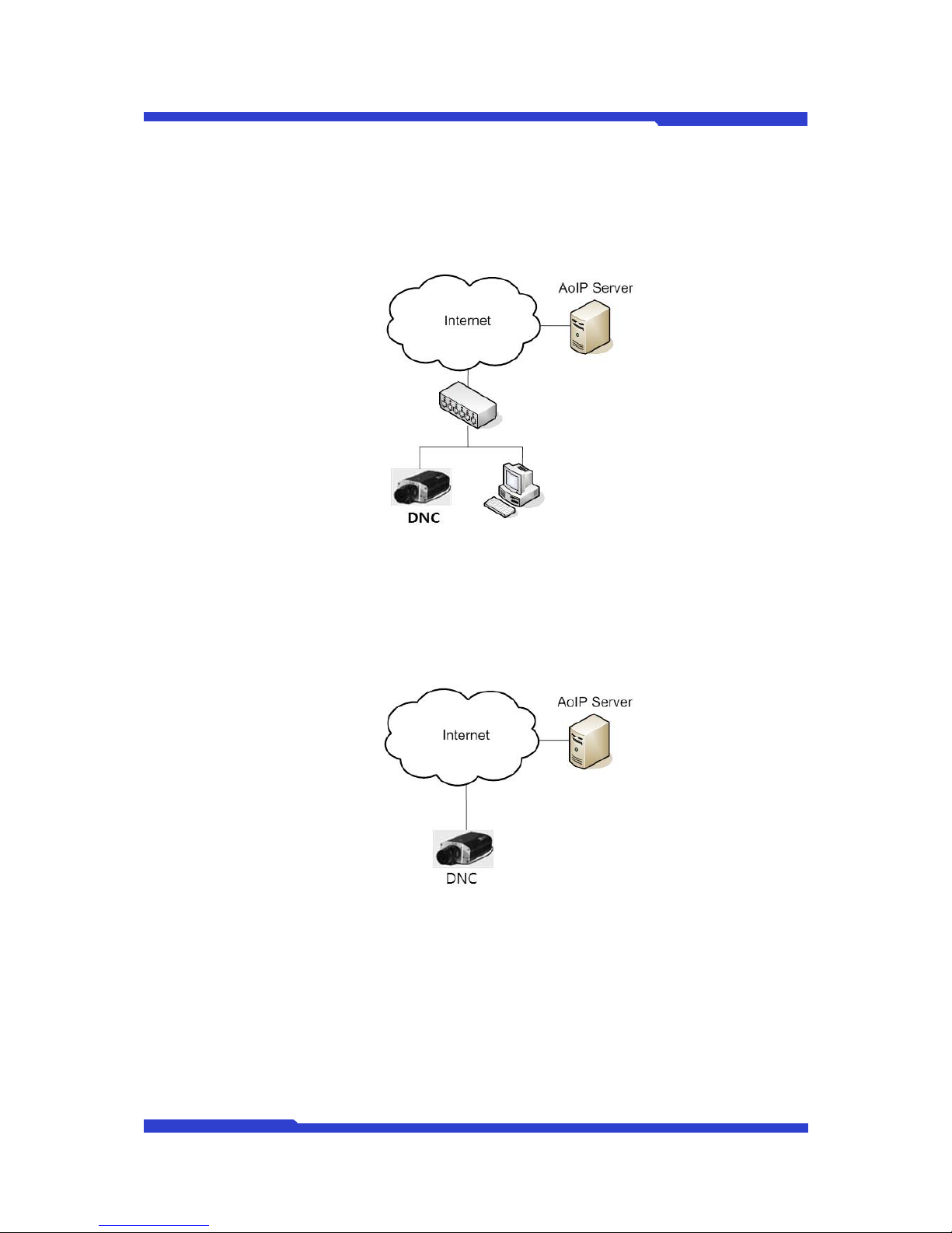
2.5.3.4. When IP sharer not to support UPnP Port mapping is installed in DNC and users
want to register DNC to AOIP server by manually do port mapping in sharer.
E. UPnP Port mapping : Manual Assigned (Port : NAT Port assigned by users)
F. AOIP Setting: Enable.
2.5.3.5. When DNC is accessible to internet and users want to register DNC to AOIP
server
G. UPnP Port mapping : Manual Assigned (Port : Default Web Port)
H. AOIP Setting : Enable
2.5.3.6. When IP sharer not to support UPnP port mapping is installed in DNC, users did
port mapping in IP sharer manually and registration of AOIP server to DNC is not
needed
I. UPnP Port mapping : Manual Assigned (Port : NAT Port assigned by users)
J. AOIP Setting: Disable.
Page 43
DNC(Dmax Network Camera) User Manual Part 2
DNC 34 Dongyang Unitech Co., Ltd
2.5.3.7. When DNC is accessible to Internet directly and registration of DNC to AOIP
server is not needed
K. UPnP Port mapping : Manual Assigned (Port : Default Web Port)
L. AOIP Setting: Disable.
2.5.3.8. DNC is installed in local network, registration of AOIP server is needed
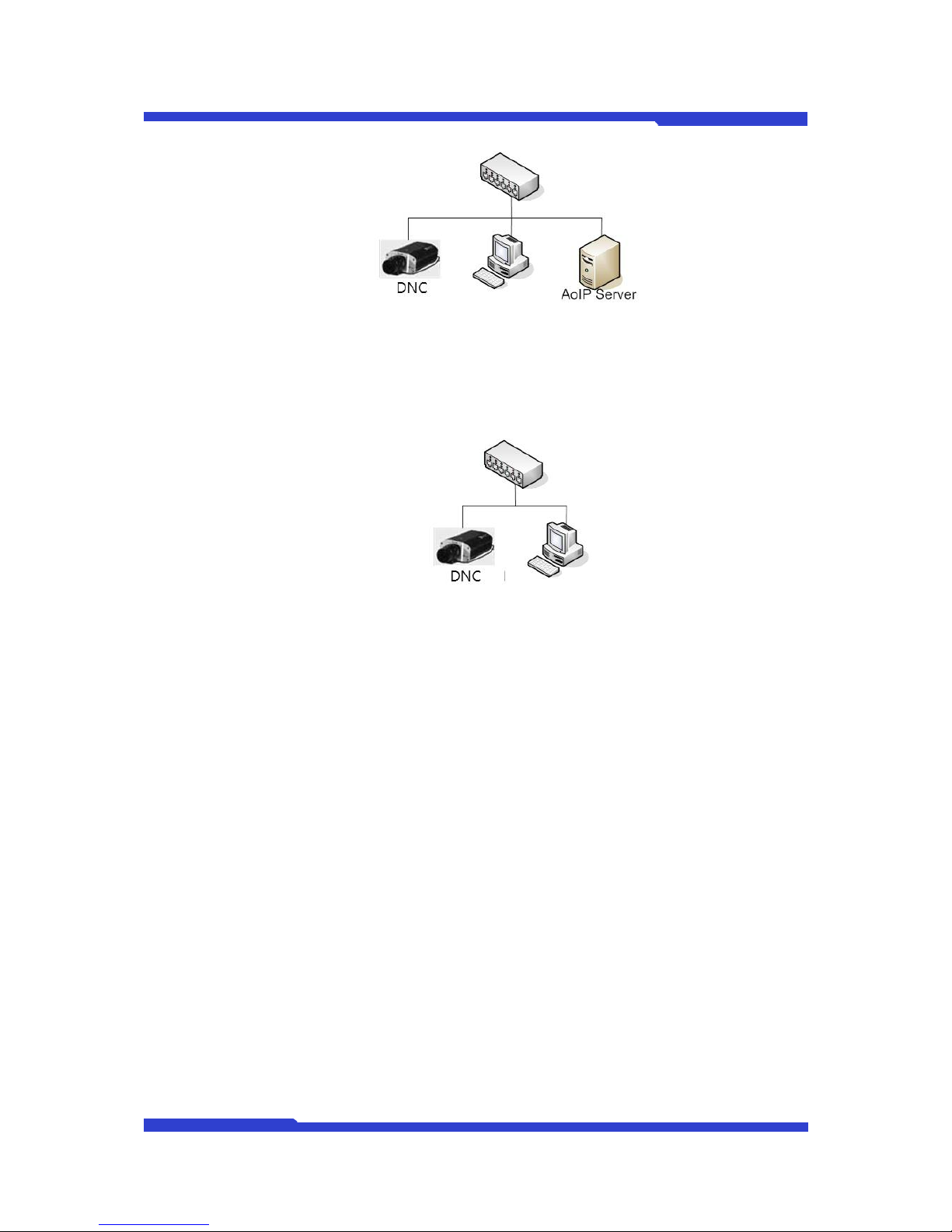
M. UPnP Port mapping : Manual Assigned (Port : Default Web Port)
N. AOIP Setting: Enable.
) AOIP server should exist in local network.
Page 44
DNC(Dmax Network Camera) User Manual Part 2
DNC 35 Dongyang Unitech Co., Ltd
2.5.3.9. DNC is installed in local network, registration of AOIP server is not needed
O. UPnP Port mapping : Manual Assigned (Port : Default Web Port)
P. AOIP Setting: Disable.
Page 45
DNC(Dmax Network Camera) User Manual Part 2
DNC 36 Dongyang Unitech Co., Ltd
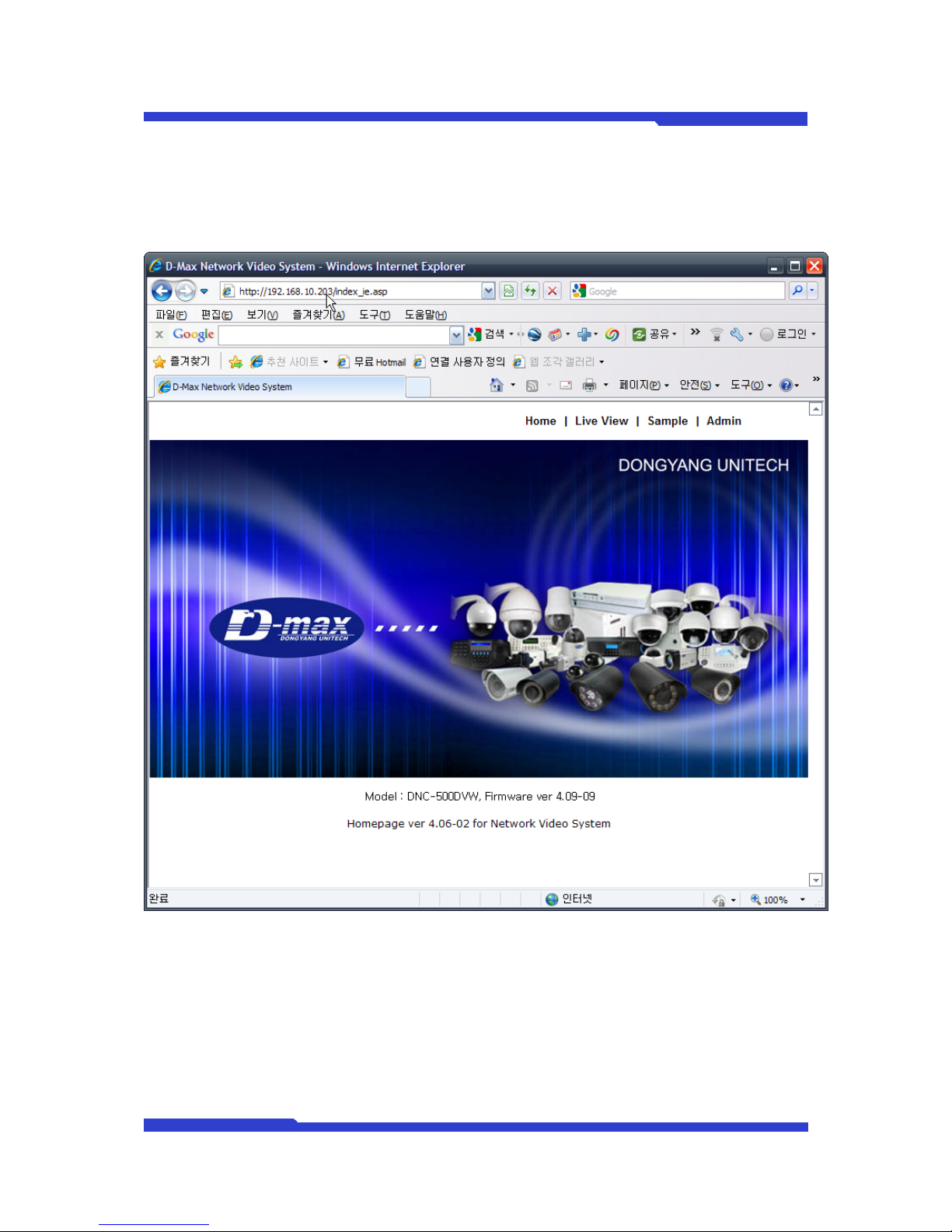
2.6. “Home” screen server through the web browser on the PC shown as
below.
Figure 26 Main page of DNC
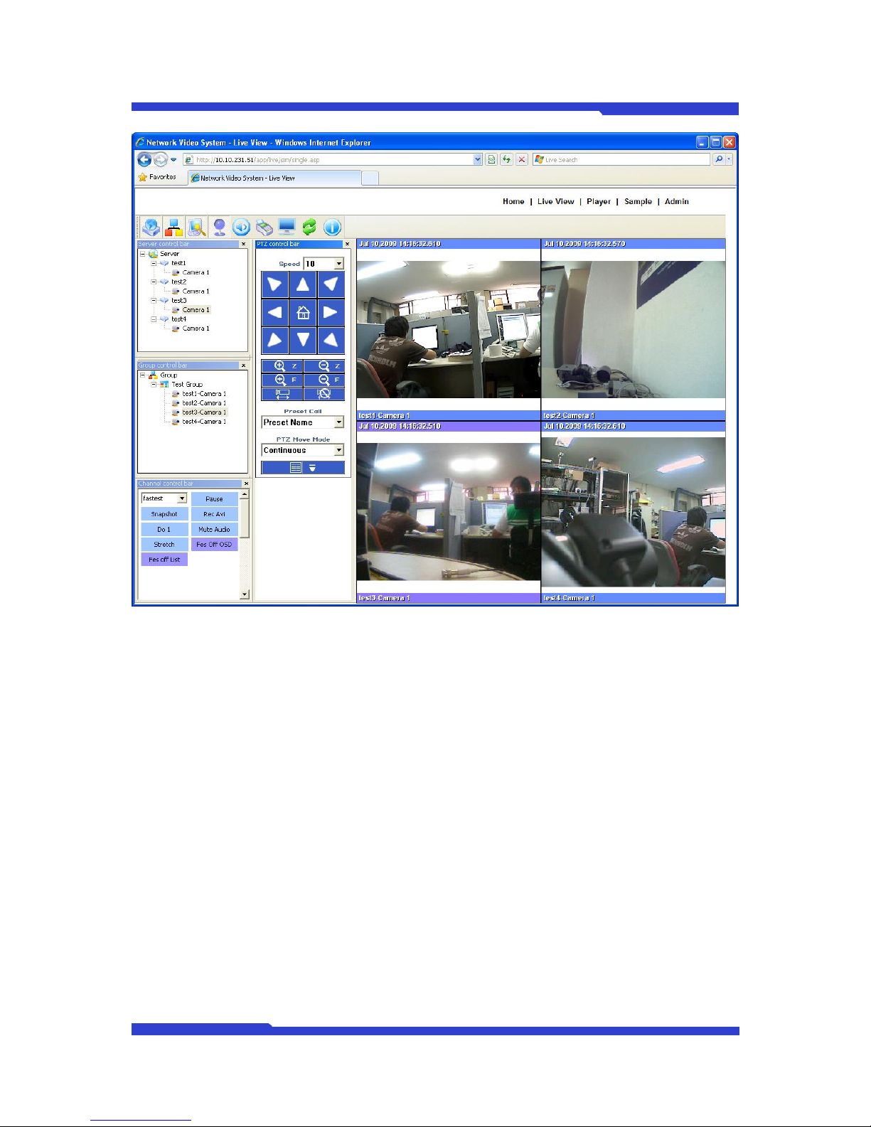
2.7. “Live View” Menu
Once users click ‘Live View’ in the upper right, SW “Smart Viewer” is installed automatically (or
manually) in PC, then real-time video of server is displayed.
Refer to Smart Viewer manual for further information.
Page 46
DNC(Dmax Network Camera) User Manual Part 2
DNC 37 Dongyang Unitech Co., Ltd
Figure 27 Screen of DNC Live View
Page 47
DNC(Dmax Network Camera) User Manual Part 2
DNC 38 Dongyang Unitech Co., Ltd
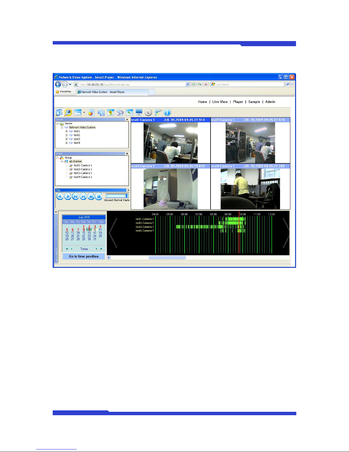
2.8. “Player” Menu (NVR only)
Figure 28 Player
This menu is for searching for videos recorded, SW “Smart Player” is installed automatically (or
manually) and users can search for videos by the condition in need after accessing to NVR.
Refer to Smart Player manual for further information.
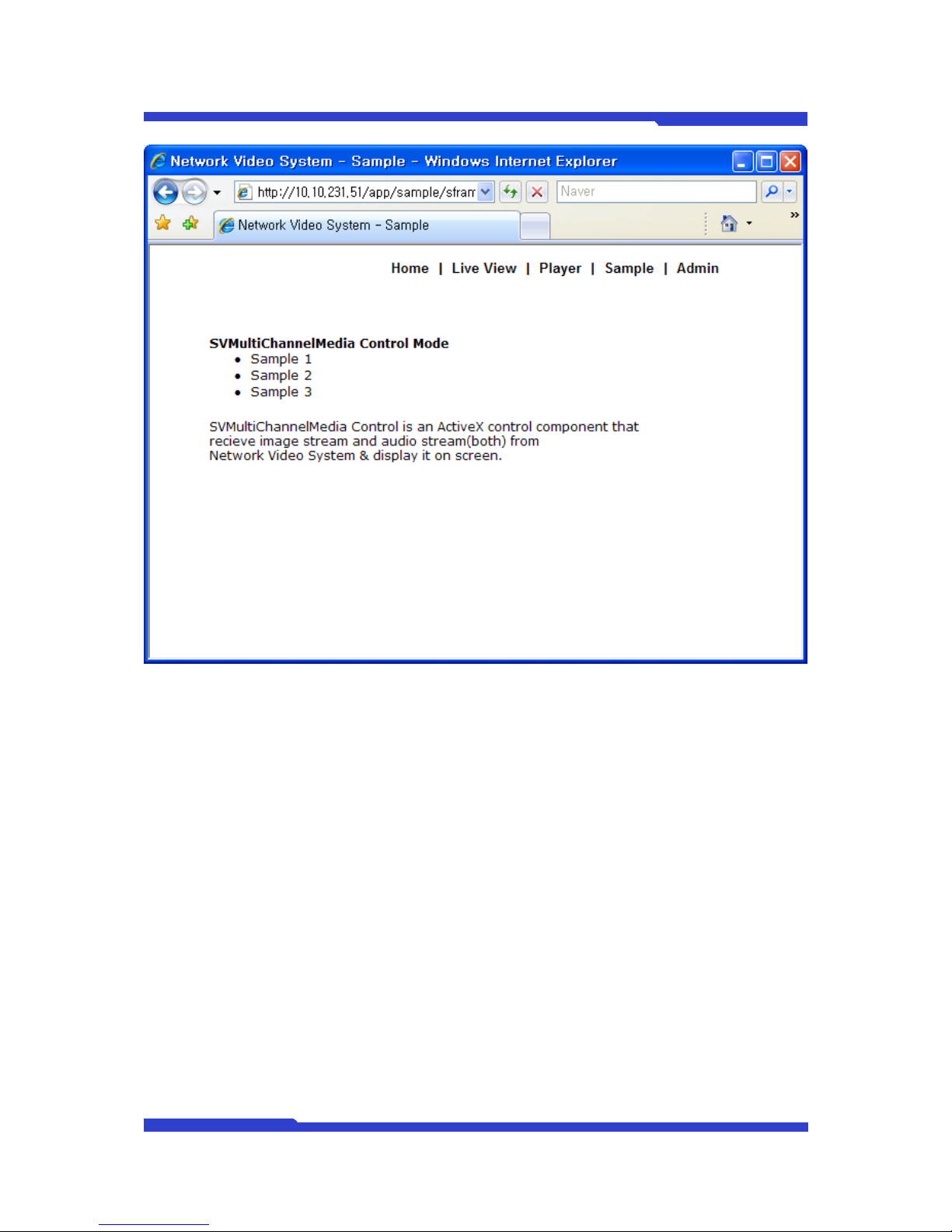
2.9. “Sample” Menu
In this menu, Sample using SDK is provided.
Sample 1 is for displaying Single stream, Sample 2 is for Single stream & PTZ control and
Sample 3 is for snapshot. Sample 2 is usable as MJPEG only. Refer to SDK for further information.
Page 48
DNC(Dmax Network Camera) User Manual Part 2
DNC 39 Dongyang Unitech Co., Ltd
Figure 29 Sample
2.10. “Admin” Menu
This menu is the administration menu for a user to manage all the functions of DNC and you
need the administrator ID and Password for this menu.
Factory default Admin ID is “root” and Password is “root” and you can change the Password in
Admin Menu. (Admin ID can’t be changed.)
Please refer to DNC User Manual Part III for more detailed information.
Page 49

DNC(Dmax Network Camera) User’s Manual Part 3
DNC 1 Dongyang Unitech Co., Ltd
DNC(Dongyang Network Camera)
User’s Manual
Part 3
(Admin Menu)
Version 4.06
December 10, 2009
Dongyang Unitech Co., Ltd
www.d-max.co.kr
www.cctvhome.net
Page 50

DNC(Dmax Network Camera) User’s Manual Part 3
DNC 2 Dongyang Unitech Co., Ltd
Index
1. Admin Menu.......................................................................................................................... 4
1.1. Entering Admin Menu ................................................................................................... 4
1.2. Admin Menu Structure .................................................................................................. 5
2. Quick Configuration .............................................................................................................. 6
2.1. Step 1: Changing Server Name .................................................................................... 6
2.2. Step 2: Time Setup ....................................................................................................... 7
2.3. Step 3: Network Setup .................................................................................................. 8
2.3.1. Static IP Configuration .......................................................................................... 8
2.3.2. DHCP Client Configuration ................................................................................... 9
2.4. Step 4: CCTVHOME DNS ............................................................................................ 9
2.5. Finish .......................................................................................................................... 10
3. System Configuration Menu ............................................................................................... 11
3.1. Server Name Setup .................................................................................................... 11
3.2. Date & Time ................................................................................................................ 12
3.3. Admin Password Configuration .................................................................................. 13
3.4. Access Control ............................................................................................................ 14
3.5. User Registration ........................................................................................................ 15
3.5.1. Add ...................................................................................................................... 15
3.5.2. Edit ...................................................................................................................... 16
3.5.3. Delete .................................................................................................................. 17
3.6. IP Devices Registration............................................................................................... 17
3.6.1. Adding VS Module ID (IP Devices) ..................................................................... 18
4. Network Configuration ........................................................................................................ 21
4.1. Network Configuration ................................................................................................ 21
4.1.1. Static IP Configuration ........................................................................................ 21
4.1.2. DHCP Client Configuration ................................................................................. 22
4.2. Network Ports ............................................................................................................. 22
4.2.1. HTTP Port ........................................................................................................... 22
4.2.2. Network Ports Configuration ............................................................................... 23
4.3. WAN (PPP, Modem) ................................................................................................... 23
4.4. Bandwidth Control Configuration ................................................................................ 23
4.5. View Network Status ................................................................................................... 24
4.6. Network Status Notify ................................................................................................. 24
4.7. CCTVHOME DNS™ ................................................................................................... 26
4.8. Port Forwarding & UPnP ............................................................................................ 27
4.9. RTP/RTSP Setup ........................................................................................................ 28
5. Device Configuration .......................................................................................................... 30
5.1. Serial Ports ................................................................................................................. 30
5.1.1. Serial Input Mode ................................................................................................ 30
Page 51

DNC(Dmax Network Camera) User’s Manual Part 3
DNC 3 Dongyang Unitech Co., Ltd
5.1.2. Serial Output Mode ............................................................................................. 32
5.1.3. Transparent Mode ............................................................................................... 32
5.1.4. PTZ Mode ............................................................................................................ 33
5.1.5. PTZ Mode ............................................................................................................ 35
5.2. Camera & Motion ........................................................................................................ 42
5.2.1. Camera & Motion ................................................................................................ 43
Camera Configuration ...................................................................................................... 44
5.3. DI (Sensor Input) / DO (Alarm Output) ....................................................................... 46
5.3.1. DI (Sensor Input) / DO (Alarm Output) ................................................................ 46
5.4. DI Status/DO Control .................................................................................................. 47
5.4.1. DI (Sensor Input) Status/DO (Alarm Output) Control .......................................... 47
6. Advanced Configuration ..................................................................................................... 47
6.1. Advanced Services ..................................................................................................... 48
6.1.1. E-mail Service Configuration ............................................................................... 49
6.1.2. FTP (Buffered) Service Configuration ................................................................. 53
6.1.3. FTP (Periodic) Service Configuration ................................................................. 56
6.1.4. Sensor Notification Service Configuration .......................................................... 59
6.1.5. Alarm Output Service Configuration ................................................................... 61
7. Utilities ................................................................................................................................ 63
7.1. System Log ................................................................................................................. 63
7.2. Save Configuration ..................................................................................................... 63
7.3. Reboot ........................................................................................................................ 64
7.4. Factory Default ............................................................................................................ 64
7.5. System Update ........................................................................................................... 65
7.5.1. All (Kernel, RAM disk, System, Web) Update ..................................................... 66
7.5.2. System and Web Update .................................................................................... 69
7.5.3. Web Only Update ................................................................................................ 70
7.5.4. PTZ Device Driver Update .................................................................................. 70
7.5.5. Sensor Device Driver Update .............................................................................. 72
7.5.6. Flexible Extra system .......................................................................................... 73
Page 52
DNC(Dmax Network Camera) User’s Manual Part 3
DNC 4 Dongyang Unitech Co., Ltd
1. Admin Menu
Admin Menu is where you can set up the most of features in DNC Servers. User ID and password
for administrator are required to log in. The factory default is root for both ID and password. Once logged
in, you can change the password to a new one.
1.1. Entering Admin Menu
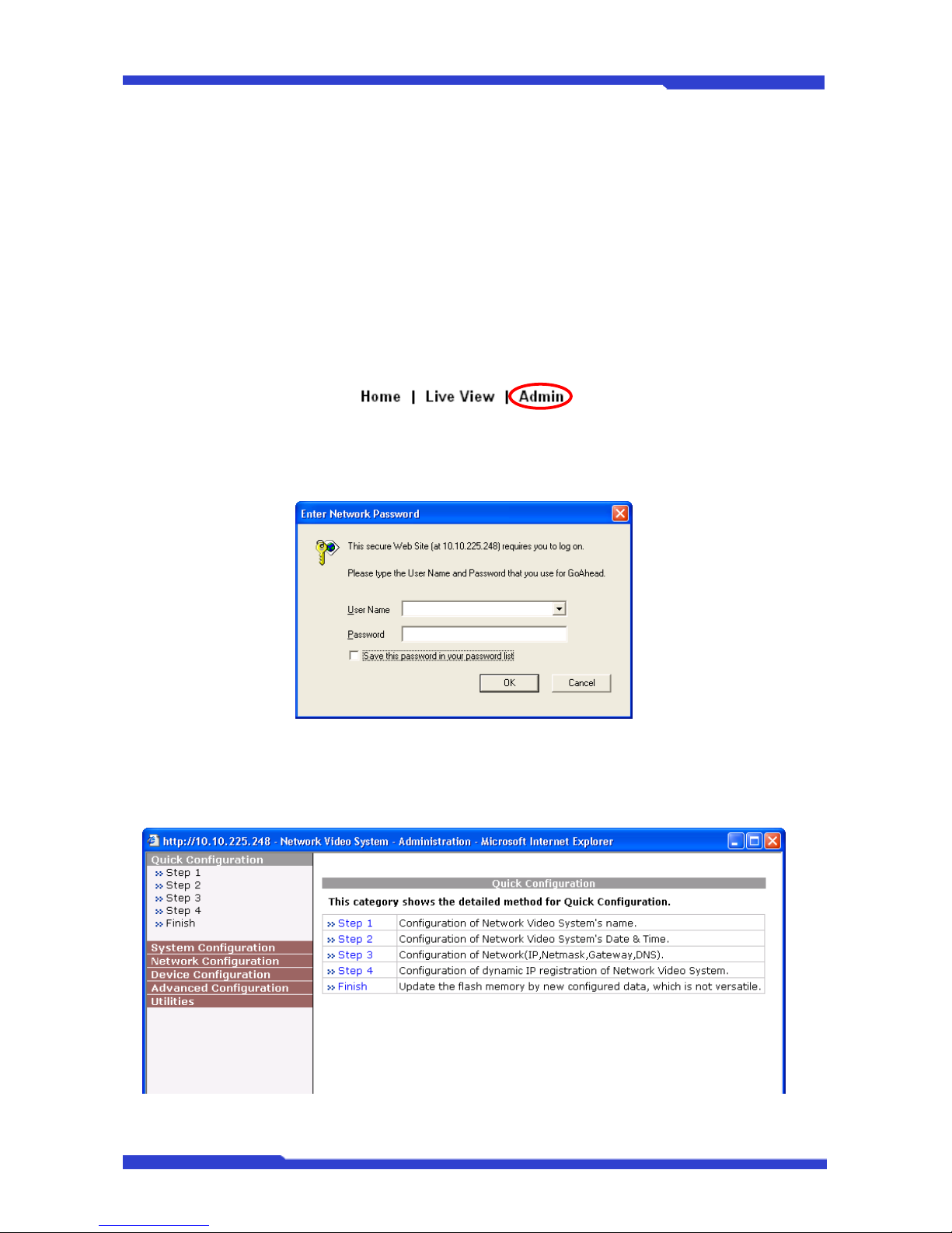
To enter Admin Menu, first connect to the DNC server. The initial menu will be displayed on the
top right part of the window. Click Admin to see a login window.
In the login window, enter root for both ID and password as they are the factory defaults. Press
Enter key or click OK button.
Now the Admin Menu will be displayed as shown below. This will guide you to the top level menu
items, which are Quick, System, Network, Device, Advanced, Recording, and Utilities. Clicking any of
these top level menu items will display submenu items and the brief descriptions.
Page 53

DNC(Dmax Network Camera) User’s Manual Part 3
DNC 5 Dongyang Unitech Co., Ltd
1.2. Admin Menu Structure
Category Main Menu Level 1 Sub-Menu Level 2 Sub-Menu
Quick configuration
Step 1
n/a n/a
Step 2
Step 3
Step 4
Step 5
Step 6
Finish
System Configuration
Server Name Setup
n/a n/a
Date & Time
Admin. Password
Access Control
User Registration
IP Devices Registration
Network
Configuration
Network Configuration
n/a n/a
PPPoE Configuration
Network Ports
WAN (PPP, Modem)
Bandwidth Control
View Network Status
Network Status Notify
CCTVHOME DNS™
Port Forwarding & UPnP
RTP/RTSP Setup Built-in Module 0 n/a
Device Configuration
Serial Ports
Serial Input Mode
Serial Output Mode
Transparent Mode
PTZ Mode
n/a
Camera & Motion
Camera 1
Camera 2
Camera 3
Camera 4
n/a
DI/DO n/a n/a
DI Status/DO Control n/a n/a
Advanced
Configuration
Advanced Services
E-mail
FTP(Buffed)
FTP(Periodic)
Sensor Notification
Alarm Output
Camera 1
Camera 2
Camera 3
Camera 4
ISENSE n/a n/a
Utilities
Save Configuration
Reboot
Factory Default
System Update
Page 54
DNC(Dmax Network Camera) User’s Manual Part 3
DNC 6 Dongyang Unitech Co., Ltd
2. Quick Configuration
2.1. Step 1: Changing Server Name
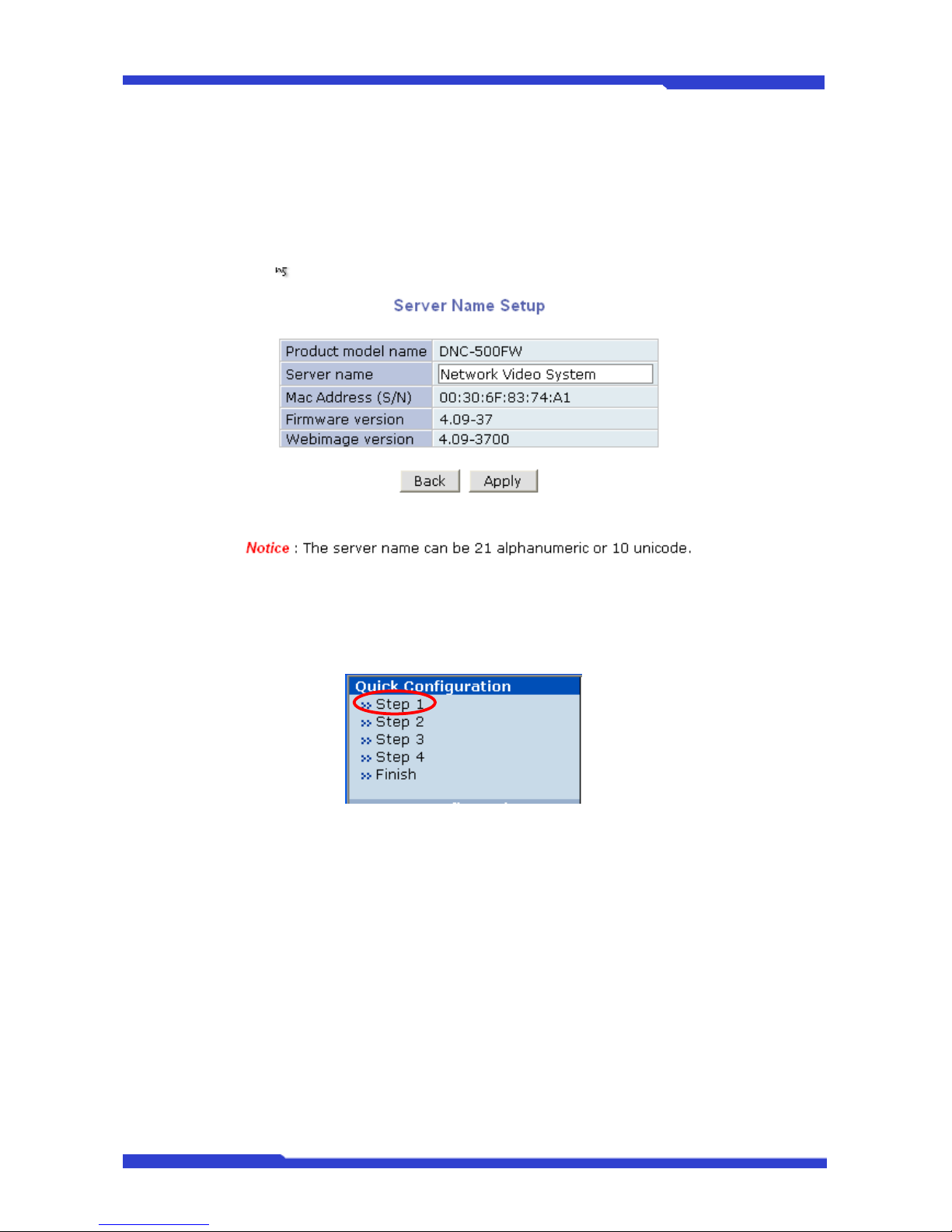
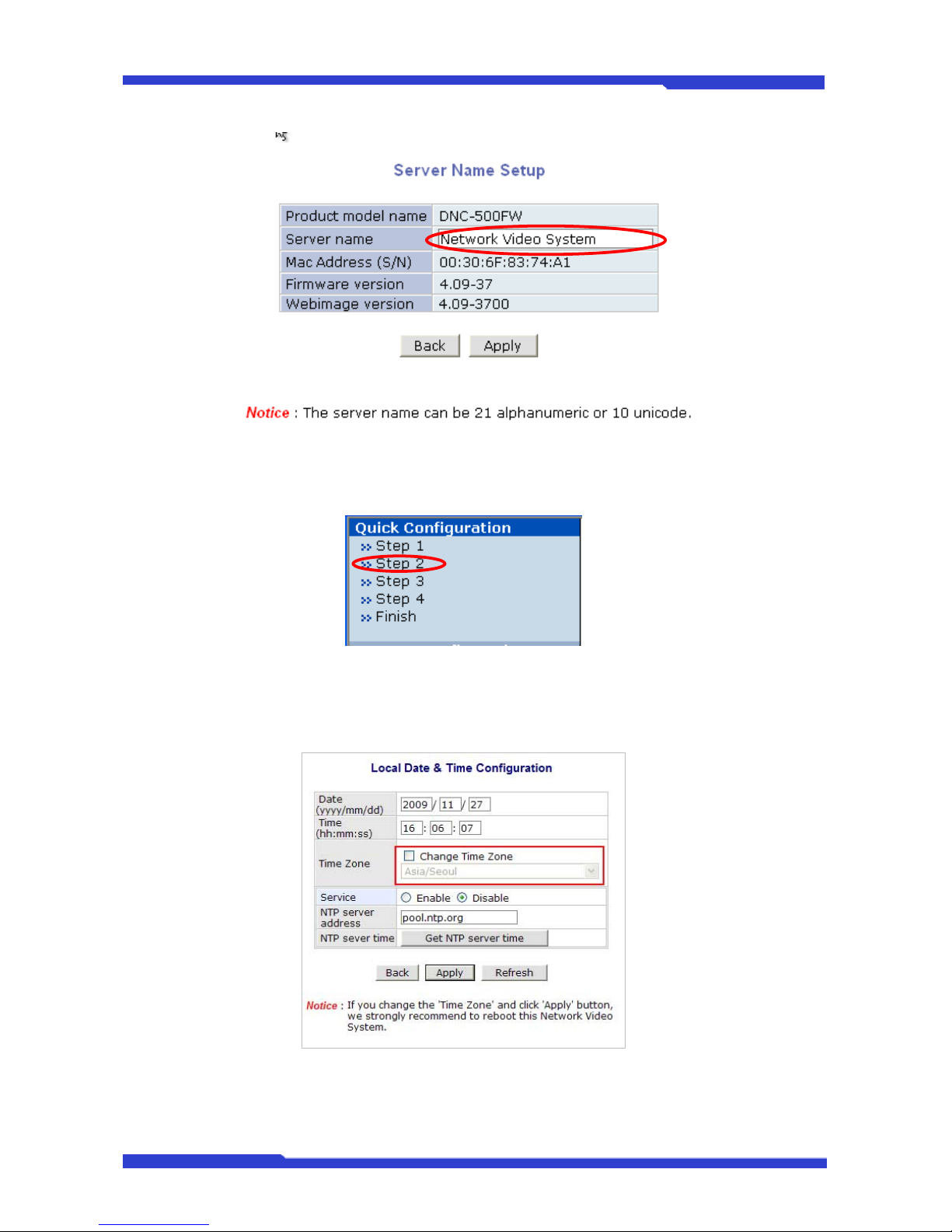
In step 1, you can find out the system information as model number of the DNC Server, server
name, MAC address (serial number), firmware version, and webimage version.
As an administrator, you can change the name of the server name here, but other values are not
allowed to change. If you want to change the server name to a new one, click Step 1 on Quick
Configuration.
Now enter a new server name. You may use up to 21 alphanumeric or up to 10 Unicode
characters. Tab or any other special characters are not allowed. Product model name, Mac Address
(S/N), Firmware version, Webimage version are not allowed to change.
After entering the new server name, click Apply button to save the setting and it will take effect
immediately.
Page 55
DNC(Dmax Network Camera) User’s Manual Part 3
DNC 7 Dongyang Unitech Co., Ltd
2.2. Step 2: Time Setup
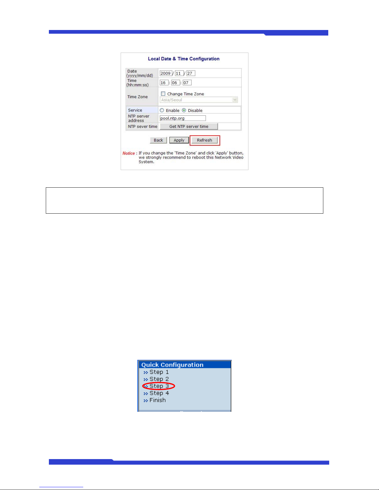
You can set up time and date here. First, click Step 2 on Quick Configuration.
Fill the Date and Time fields with your local time and date information. If you're in a different time
zone, put a checkmark on Change Time Zone, then select the correct region from the list box. To take
the time zone change in effect, you need to click Apply button and reboot the system.
If you only changed Date and Time setting, you simply click Apply button to take it into effect
immediately. If you want to retrieve the exact current time from NTP server on the network, click Get NTP
Server Time button. Clicking Refresh button will display the date and time retrieved from DNC® Server.
Page 56
DNC(Dmax Network Camera) User’s Manual Part 3
DNC 8 Dongyang Unitech Co., Ltd
) In order to retrieve Time and Date information from a NTP server, you need to put NTP server
address in advance of setting up, such as pool.ntp.org.
2.3. Step 3: Network Setup
To make a connection to the Internet, it is required to figure out the type of the Internet service
you’re using. Depending on the service type, the network configuration can be in any of Static IP, DHCP
Client, or PPPoE. You need to set up the DNC Server according to your network type.
• Static IP: The DNC Server is assigned a permanent fixed IP address.
• DHCP Client: In this case, ISP or network gateway is running a DHCP server. Most of ISP
services such as cable modem or DSL are providing this type of service. DNC server needs to
be configured to be DHCP Client so that it can be assigned a dynamic IP address.
• PPPoE: Many of DSL services over phone line are providing this type of Internet connection. It
can be used in password-based authentication environment.
2.3.1. Static IP Configuration
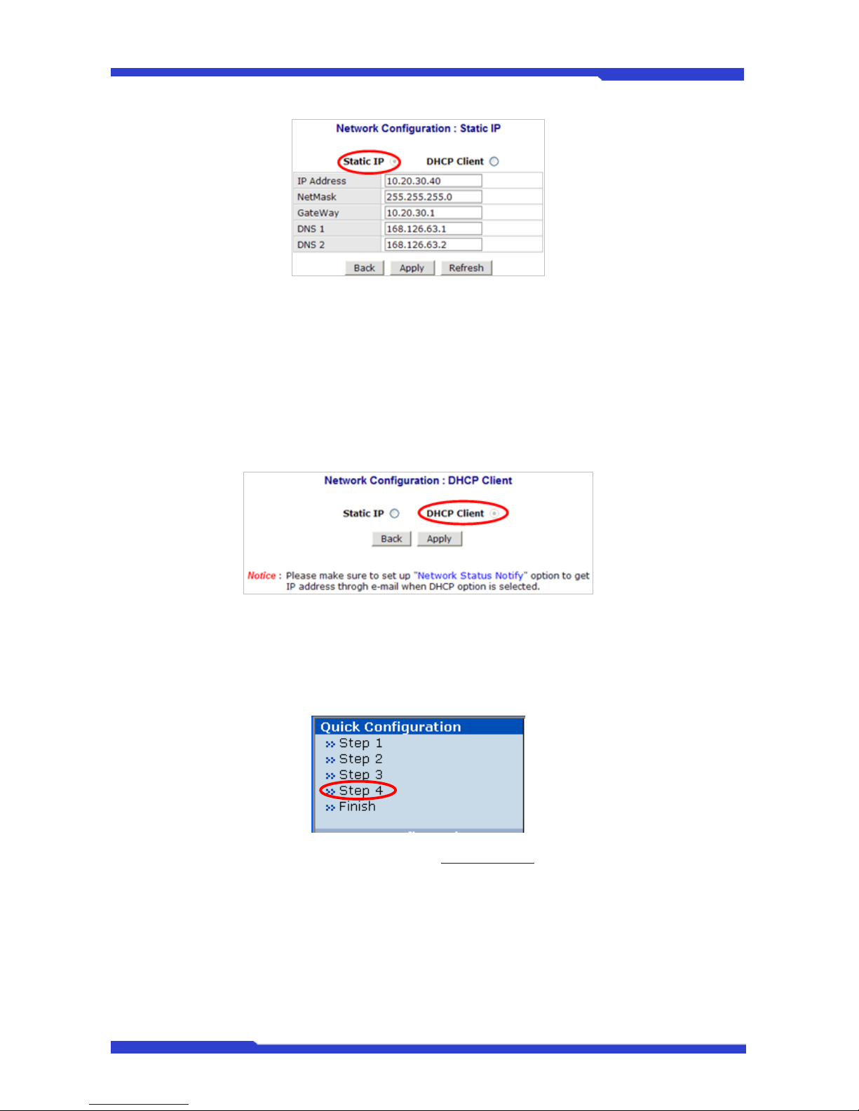
Click on Step 3, then the network configuration window will be displayed.
Select Static IP, and you will be able to change IP Address, NetMask, Gateway, DNS1, and
DNS2 fields.
Page 57
DNC(Dmax Network Camera) User’s Manual Part 3
DNC 9 Dongyang Unitech Co., Ltd
Enter the pre-assigned IP Address, NetMask, Gateway, DNS1, and DNS2 values respectively.
Click Apply button to save the settings. If you don’t want to save it, click Back button. Clicking
Refresh button will restore the condition back to the original before clicking Apply.
2.3.2. DHCP Client Configuration
The default network type is set to DHCP Client and default DNS is set to KT DNS in DNC Servers.
Selecting DHCP Client on the Network Configuration will show the window shown below. Click Apply
button to save the setting. Otherwise, click Back button.
2.4. Step 4: CCTVHOME DNS
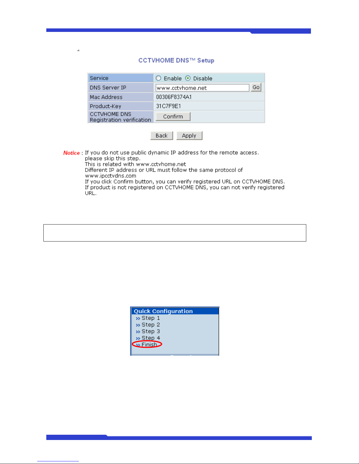
When DNC Server is used in a Dynamic IP environment, it is required to utilize CCTVHOME DNS
feature. In Step 4 of Quick Configuration menu, you set DNC server to inform the CCTVHONME DNS
of the IP address being used.
First, you need to register in CCTVHOME DNS at http://cctvhome.
net to have a user account. Next,
enter the MAC address and the product key, and configure CCTVHOME DNS accordingly, then DNC
Server becomes accessible from you all the time even in Dynamic IP environment.
To start using CCTVHOME DNS feature, select the Enable on the service field. Enter the address
of the CCTVHOME DNS Server that the system is registered in. Click Apply button to save the setting.
Page 58
DNC(Dmax Network Camera) User’s Manual Part 3
DNC 10 Dongyang Unitech Co., Ltd
9 The address of IP-CCTV DNS™ Server is http://www.cctvhome.net.
) Refer to CCTVHOME DNS
™
User’s Manual for further details of the configuration.
9 After the DNC server is successfully registered in CCTVHOME DNS™, you can
check the Internet URL by clicking Confirm button.
2.5. Finish
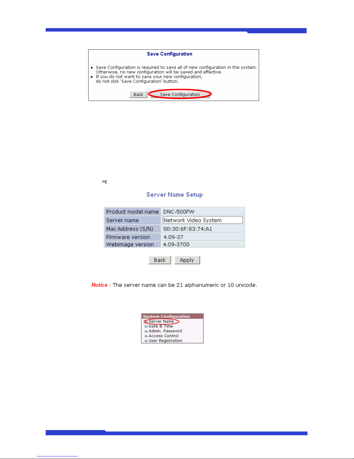
You need to save all the changes to the Flash Memory after finishing the configuration. The
changes made to DNC Server will be permanent by this step. Click Finish on Quick Configuration
menu.
Click Save Configuration button. This will write the new settings to the system’s flash memory. If
you don’t want to save them, click Back button.
Page 59
DNC(Dmax Network Camera) User’s Manual Part 3
DNC 11 Dongyang Unitech Co., Ltd
3. System Configuration Menu
3.1. Server Name Setup
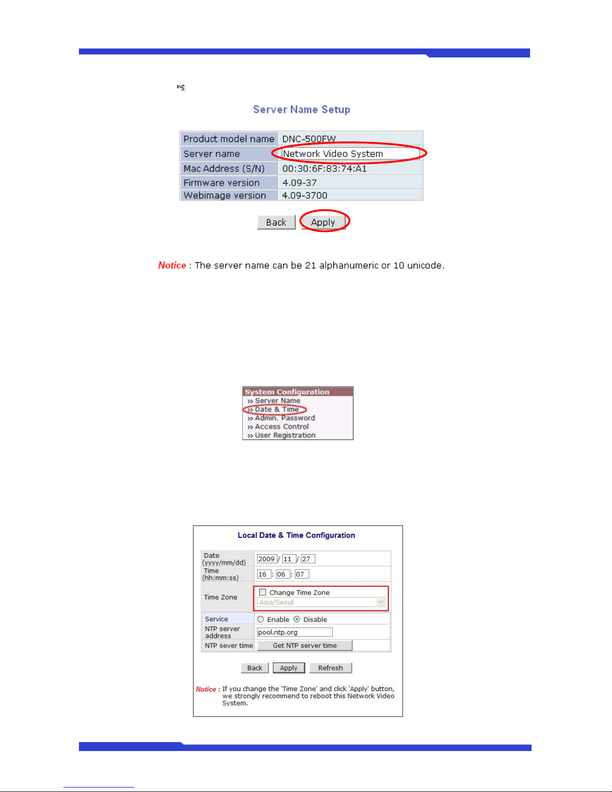
You can find the system information such as the model number of DNC Server, server name, MAC
address (serial number), firmware version, and webimage version. As an administrator, you can change
the name of the server name here, but other values are not allowed to be changed.
Click Server Name on the System Configuration menu.
For a new Server Name, you may use up to 21 alphanumeric or up to 10 Unicode characters. Tab
or any other special characters are not allowed. You are not allowed to change Product model name,
MAC Address (Serial Number), Firmware version, and Webimage version. They are all remained in
original condition.
Page 60
DNC(Dmax Network Camera) User’s Manual Part 3
DNC 12 Dongyang Unitech Co., Ltd
After entering the new server name, click Apply button to save the setting. In this case, the new
server name takes effect immediately.
3.2. Date & Time
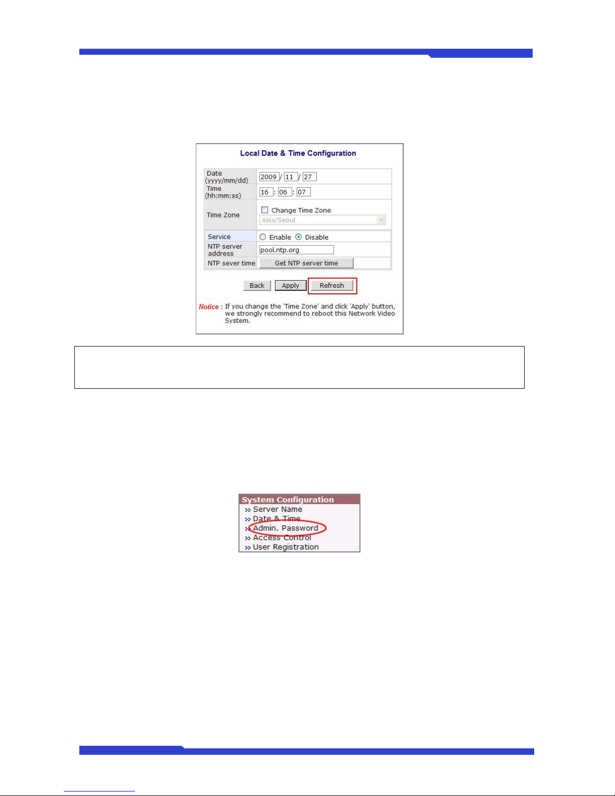
Click Date & Time on System Configuration menu. Local Date & Time Configuration window will
be displayed.
Fill the Date and Time fields with your current local time and date information. If you're in a
different time zone, put a checkmark on Change Time Zone checkbox, then select a correct region from
the list box. To put the time zone change in effect, you need to click Apply button and reboot the system.
Page 61
DNC(Dmax Network Camera) User’s Manual Part 3
DNC 13 Dongyang Unitech Co., Ltd
When you changed only Date and Time, you simply click Apply button to take it into effect
immediately. If you want to retrieve the exact current time from NTP server over the network, click Get
NTP server time button. Clicking Refresh button will display the date and time from DNC® Server.
) In order to retrieve Time and Date information from a NTP server, you need to put NTP server
address in advance, such as pool.ntp.org.
3.3. Admin Password Configuration
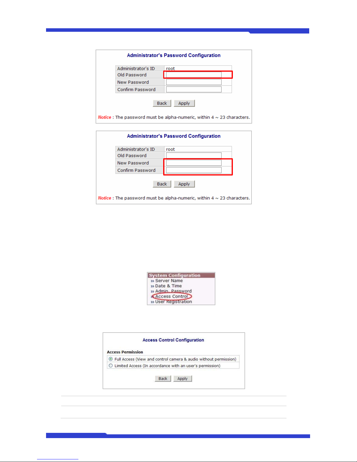
In this menu, you can change the password for admin account. Default ID for admin account is
fixed as “root” and not allowed to change. To change the password for admin, click Admin Password on
System Configuration menu.
In Old Password field, enter the current password. In both New Password and Confirm
Password fields, enter the same new password. The password must be between 4 and 23 alphanumeric
characters.
Page 62
DNC(Dmax Network Camera) User’s Manual Part 3
DNC 14 Dongyang Unitech Co., Ltd
Click Apply button to put it into effect. Because you have replaced the password with a new one,
the existing network connection made with old password to DNC Server is lost now. In this case, you
have to reconnect to the DNC server using new password.
3.4. Access Control
In this menu, you can define the accessibility and privileges of users. To start to configure, click
Access Control on System Configuration menu.
From the Access Permission window, select either one you would like to use. Click Apply button
to save the change.
Full Access Any user can access the server and use all the features without limit.
Limited Access Only registered users can access the server and have limited privileges.
Page 63
DNC(Dmax Network Camera) User’s Manual Part 3
DNC 15 Dongyang Unitech Co., Ltd
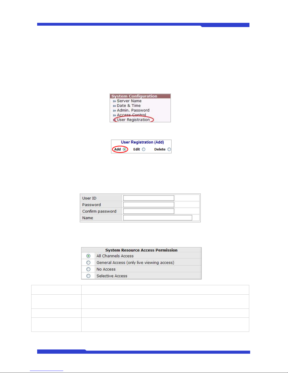
3.5. User Registration
You can add, modify, or delete users for your DNC® Server in User Registration. Once registered
as Limited Access setting, the user can access the DNC Server with limited privileges.
3.5.1. Add
When Add is selected, you can add users and define their passwords, names, and access
permission levels respectively. To add a user, click User Registration on System Configuration menu.
Next, select Add, then the User Registration (Add) selection screen will be displayed.
Enter a user ID, which must consist of up to 23 alphanumeric characters. In both Password and
Confirm Password fields, enter the identical password respectively. The password must be between 4
and 23 alphanumeric characters. In Name filed, enter the user’s name that must be up to 31
alphanumeric or 15 Unicode characters.
Now select one of the four items from System Resource Access Permission, which defines the
permission level for registered users to the DNC server.
All Channels Access User can use all the features except for Configuration in Admin Page.
General Access (only
live viewing access)
User can use only Live View, but not PTZ, Audio, or DI/DO control.
No Access User is not allowed for any of the features.
Selective Access
User is allowed to use only the selected features. With this item selected, user can
now configure the details under the menu.
Page 64
DNC(Dmax Network Camera) User’s Manual Part 3
DNC 16 Dongyang Unitech Co., Ltd
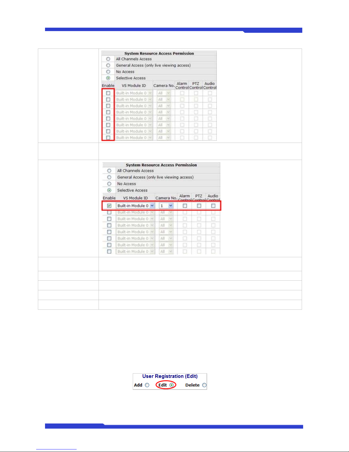
Enable
DNC Server can have multiple VS modules registered in it. When user ticks on any
of Enable checkboxes, other fields in that row are enabled to select.
VS Module ID
The registered user can select VS Modules that are available.
(VS Module is a network device that has been registered in DNC® Server)
Camera No. Among the cameras of VS Module, select one to set up. (between 1 and 4)
Alarm Control Determine if Alarm is to be used.
PTZ Control Determine if PTZ Control is to be used.
Voice Control Determine if Audio Control is to be used.
After finishing the registration process, click Apply button to add the user.
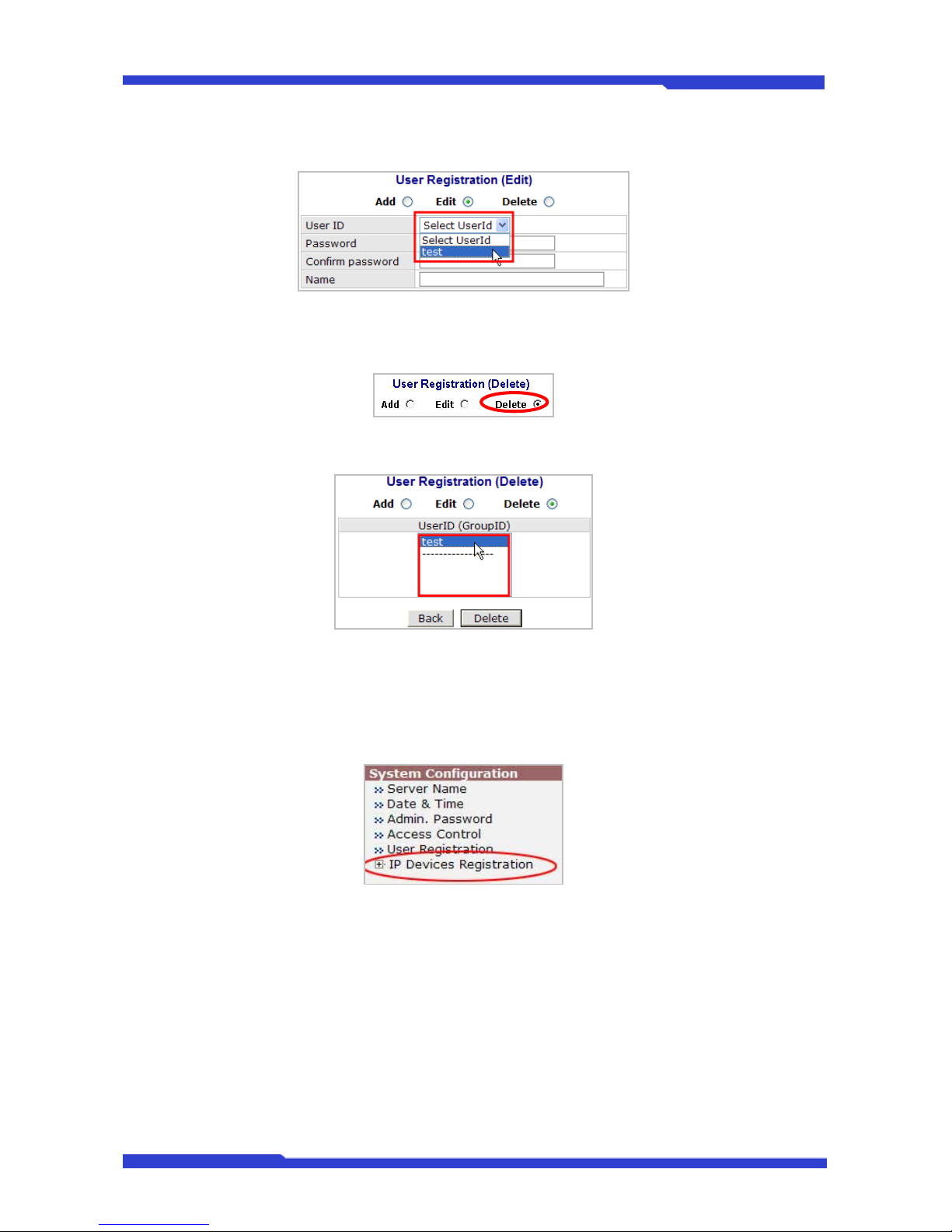
3.5.2. Edit
When Edit is selected, you can modify the existing user’s name, password, and access permission.
User ID is not allowed to change. Once selecting a user ID for edit, the usage is the same as in Add
section.
To edit a user account, select Edit.
To see existing users, click Select UserId, and select a user to be edited. Then change the
password, name, or access permission, and click Apply button to save the setting. Setup of Access
Page 65
DNC(Dmax Network Camera) User’s Manual Part 3
DNC 17 Dongyang Unitech Co., Ltd
Permission can be done the same way as in Add section.
3.5.3. Delete
To delete an existing user, select Delete.
From the list of the users, select a user to delete. Click Delete button to confirm the deletion.
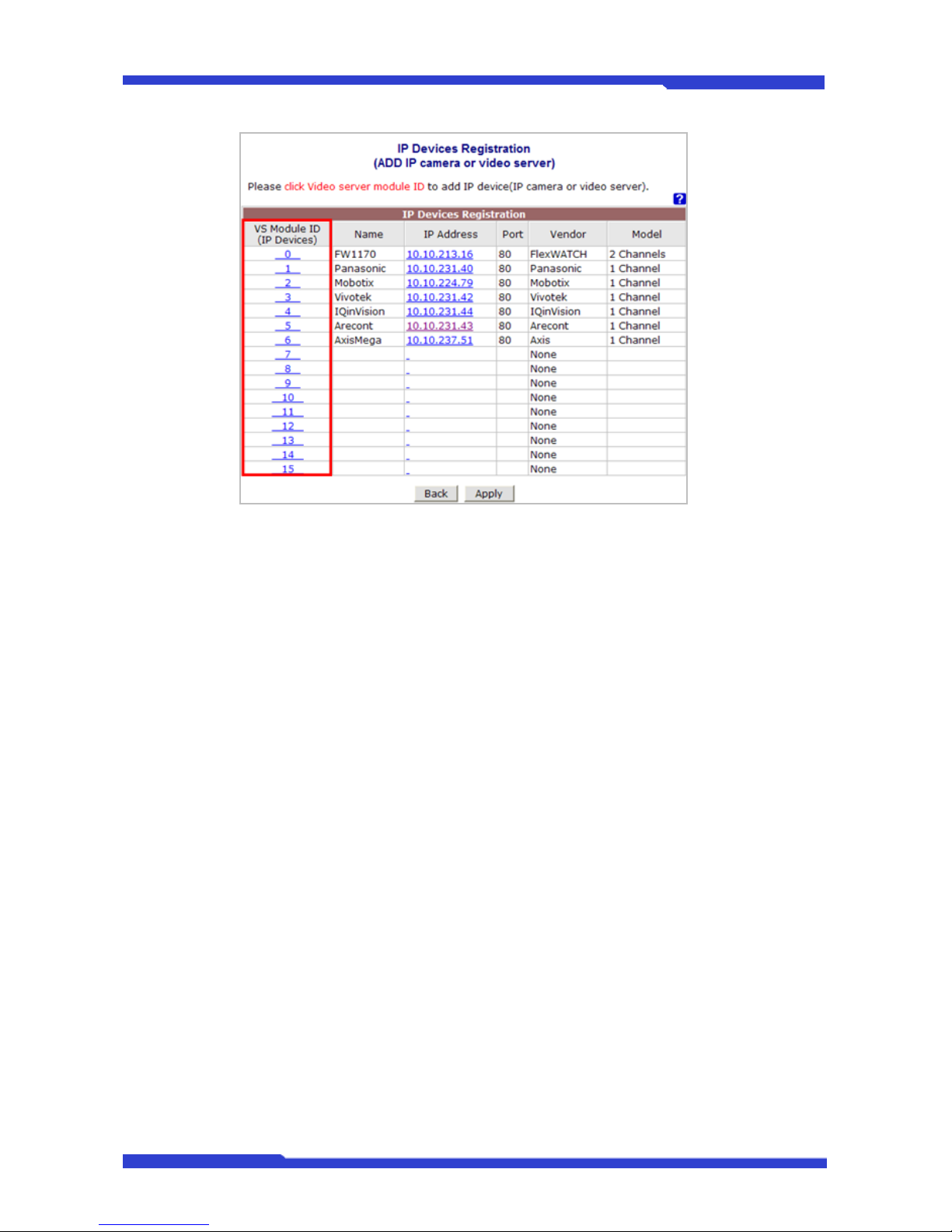
3.6. IP Devices Registration
In this section, you can add NVS (Network Video Server) and NCS (Network Camera Server) to
the NVR (Network Video Recorder) as remote server devices. Click IP Devices Registration on System
Configuration menu.
Select one of the VS Module ID (IP Devices) from the list to add as a remote server. DNC Server
supports vendors such as Axis, Panasonic, Vivotek and more than 10 others as well as DNC products.
When multiple servers are added, the maximum number of total channels from the servers can’t exceed
16.
Page 66
DNC(Dmax Network Camera) User’s Manual Part 3
DNC 18 Dongyang Unitech Co., Ltd
Each IP NVR model has different number of supported channels which can be added.
9 FW-5050: Up to 8 channels including other vend or’s model (3M pixel supported)
9 FW-5071: Up to 16 channels including other vendor’s model (3M pixel supported)
9 FW-5450: Up to 16 channels including other vendor’s model and analog (D1 supported)
9 FW-5850: Up to 16 channels including other vendor’s model and analog (D1 supported)
After addition VS Module ID (IP Devices), click Apply button to store the setting.
3.6.1. Adding VS Module ID (IP Devices)
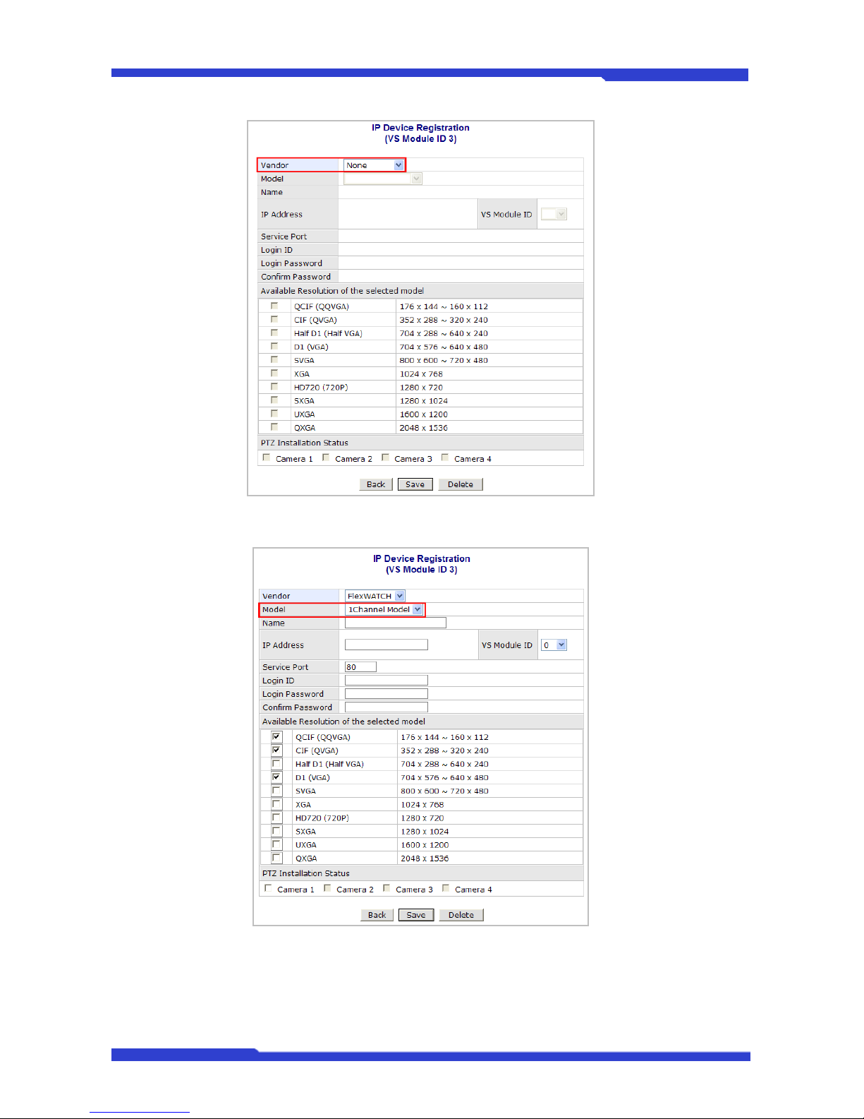
Select an item from VS Module ID (ID Devices), and choose the vendor name of the server.
Page 67
DNC(Dmax Network Camera) User’s Manual Part 3
DNC 19 Dongyang Unitech Co., Ltd
Select the number of channels to add.
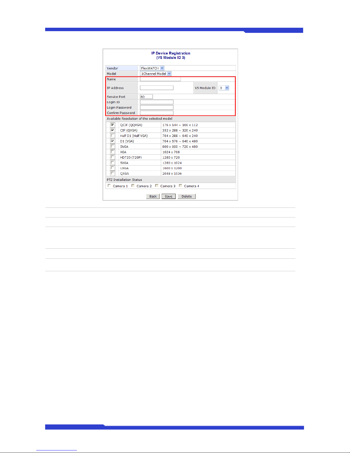
Now enter the name of the server, IP Address, VS Module ID (for DNC only), Server Port, Login
ID/Password
Page 68
DNC(Dmax Network Camera) User’s Manual Part 3
DNC 20 Dongyang Unitech Co., Ltd
Name Name of the server to add
IP Address IP Address of the server to add
VS Module ID Applicable to DNC only. Enter 0 for other vendor’s models.
Service Port Web port number of the server
Login ID / Password
/ Confirm Password
User ID and Password of the server
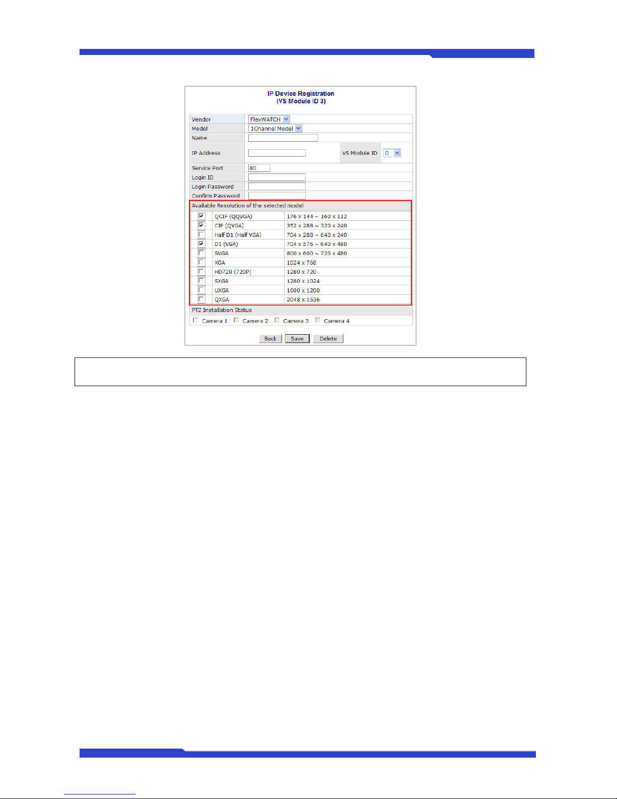
Select the video resolution of the server to add. Put check marks on the resolutions supported by
the server you’re adding here.
Page 69
DNC(Dmax Network Camera) User’s Manual Part 3
DNC 21 Dongyang Unitech Co., Ltd
) Please refer to the User’s Manual of each product to find out the supported resolutions.
If PTZ functionality is provided by the server, put check marks on Camera 1 to 4 on PTZ
Installation Status. Then you will be able to control each camera’s PTZ in Live Viewer.
After setup is finished, click Save button to add the server, and later click Apply button in IP
Device Registration to take the changes into effect. If Delete button is pressed, the added server is
removed from the setup and Live Viewer doesn’t provide you the video.
4. Network Configuration
4.1. Network Configuration
To make a connection to the Internet, it is required to figure out the type of the Internet service
you’re using. Depending on the service type, the network configuration can be in any of Static IP, DHCP
Client, or PPPoE. You need to set up the DNC Server according to your network type.
• Static IP: The DNC Server is assigned a permanent fixed IP address.
• DHCP Client: In this case, ISP or network gateway is running a DHCP server. Most of ISP
services such as cable modem or DSL are providing this type of service. DNC server needs to
be configured to be DHCP Client so that it can be assigned a dynamic IP address.
• PPPoE: Many of DSL services over phone line are providing this type of Internet connection. It
can be used in password-based authentication environment.
4.1.1. Static IP Configuration
Click Network Configuration on Network Configuration menu.
Page 70
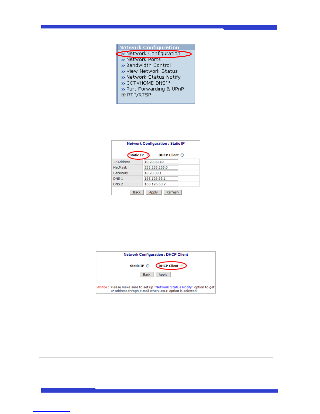
DNC(Dmax Network Camera) User’s Manual Part 3
DNC 22 Dongyang Unitech Co., Ltd
When you select Static IP, the Static IP configuration screen will be displayed. You can change IP
Address, NetMask, Gateway, DNS1, and DNS2 here. If you’re given new values for those fields, enter
them in each input box.
Click Apply button to save the change. If you don’t want to save it, click Back button. Clicking
Refresh button will restore the original condition.
4.1.2. DHCP Client Configuration
The default condition of Network Configuration is DHCP Client. With DHCP Client selected, click
Apply button to save the change. If you don’t want to save it, click Back button.
4.2. Network Ports
In this configuration, you set up the HTTP port for DNC® Server to communicate with the Client PC.
4.2.1. HTTP Port
This is the network port that is used when a Client PC connects to the DNC® Server’s Web page.
It can be assigned between 80 and 65535 and the default value is 80.
) If the HTTP port number is changed to other value than default (80), make sure the new HTTP
port number goes together with the DNC Server's Internet address. For example, when DNC’s IP
address is 192.168.1.00 and set the HTTP port to 8080, you will have to enter
Page 71
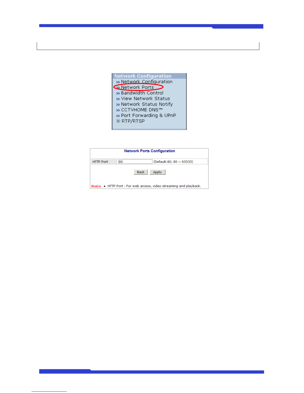
DNC(Dmax Network Camera) User’s Manual Part 3
DNC 23 Dongyang Unitech Co., Ltd
http://192.168.1.100:8080 to connect to the server.
4.2.2. Network Ports Configuration
Click Network Ports on Network Configuration menu.
Enter an HTTP port number you want to use, and click Apply button to save the change.
4.3. WAN (PPP, Modem)
If the DNC Server has a PSTN modem, this section needs to be configured to make a PPP
connection through the modem.
9 PSTN: Dialup telephone line provided telecommunication companies
9 PPP: Asynchronous network protocol mostly used to provide TCP/IP on telephone lines
4.4. Bandwidth Control Configuration
With this feature, you can set the maximum network traffic on DNC® Server. If there occurs more
network traffic than you set up here, DNC® server randomly drops any of the data packets to limit the
total bandwidth.
To configure, click Bandwidth Control on the menu, and the configuration window will be
displayed. If bandwidth control feature is to be used, select Enable. Enter the maximum bandwidth you
desire in Bandwidth Limit box. The maximum bandwidth is total sum of all the packet data which
includes M-JPEG, MPEG-4, and H.264. Click Apply to save the change.
Page 72
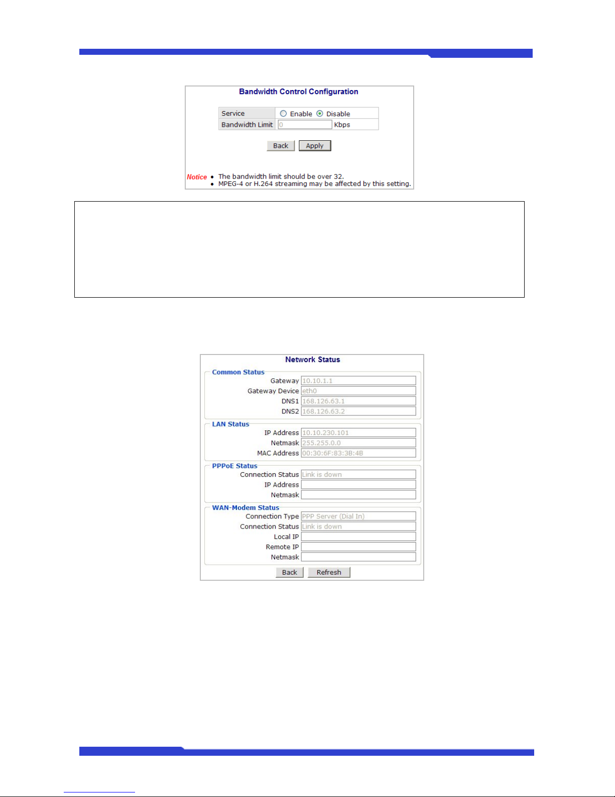
DNC(Dmax Network Camera) User’s Manual Part 3
DNC 24 Dongyang Unitech Co., Ltd
) This bandwidth control feature works fairly well in M-JPEG video transmission. But, for MPEG-4
and H.264, dropping data packets may cause low quality of video, so it is recommended to utilize
CBR and frame rate control instead of bandwidth control for MPEG-4 and H.264 video.
) Network Bandwidth control is managed by DNC® Server and it drops any data packets if
required, thus you may experience slow connection to the server when the feature is enabled.
4.5. View Network Status
You can see the status of the DNC® Server with this feature. Click Refresh button to reload the
updated information from the server.
4.6. Network Status Notify
If Network Status Notify is set to Enable, DNC Server’s network status will be emailed to a
specific person in case of the following events:
• When it is set to Dynamic IP on Network Configuration menu, and the DNC server has
been given a new dynamic IP address and connected to the network.
Or,
• When it is set to PPP Client on WAN-Modem menu, and the DNC server has been
connected to the network with ISP or PPP server.
To configure, click Network Status Notify on Network Configuration.
Page 73
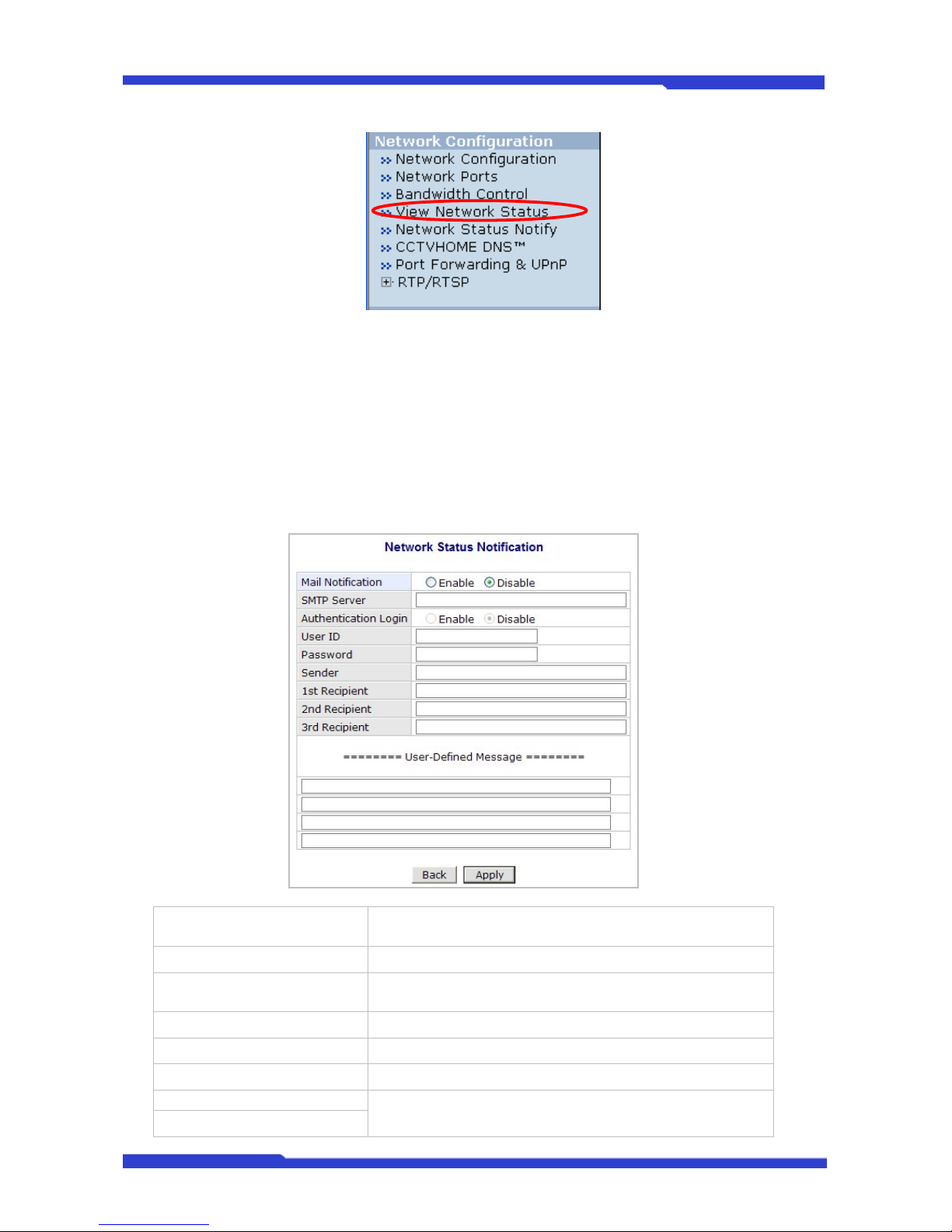
DNC(Dmax Network Camera) User’s Manual Part 3
DNC 25 Dongyang Unitech Co., Ltd
Network Status Notification window will be displayed. First, select Enable to use the feature.
Then enter the address of the SMTP server which is needed for email service. If your SMTP server
requires a user ID and a password for authentication, you will have to get them from ISP or network
admin. Enter the ID and password.
In Sender field, enter your email address or other meaningful words that will show the message
was sent from the DNC server as a notification. Now enter the email addresses of the recipients in the
three Recipient fields, up to 3 persons. In the User-Defined Message box, you may want to put the
message to explain why the message was sent. After finishing the setup, click Apply to save the setting.
Mail Notification
Enable: Send email
Disable: Do not send email
SMTP Server SMTP Server address for email service
Authentication Login
Enable: user ID and password is required for SMTP server
Disable: user ID and password not required
User ID User ID for SMTP server
Password Password for SMTP server
Sender Email address of Sender
1st Recipient
Email Addresses of the Recipients (up to 3 persons)
2nd Recipient
Page 74
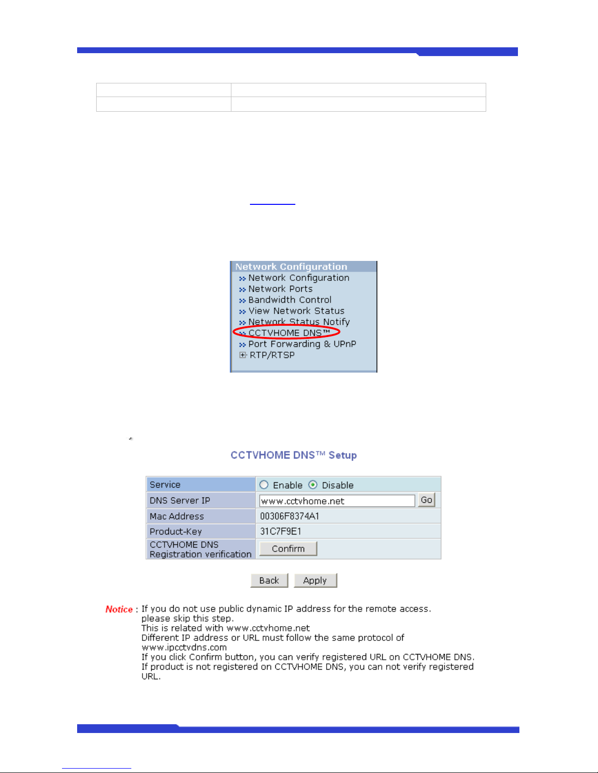
DNC(Dmax Network Camera) User’s Manual Part 3
DNC 26 Dongyang Unitech Co., Ltd
3rd Recipient
User Defined Message Message to be included in the Notification email
4.7. CCTVHOME DNS™
If a DNC® Server is operating in a dynamic IP environment, then CCTVHOME DNS™ service
should be used in order to make a connection to it. Before configure the server, you first need to get a
user account from CCTVHO ME DNS™ (http://www.
cctvhome.net), and register the MAC address and
the product-Key of your DNC® Server.
To set up the usage of CCTVHOME DNS™ in the DNC® Server, click CCTVHOME DNS™ on
Network Configuration menu.
Select Enable on Service field, then enter the address of CCTVHOME DNS™ Server that your
DNC server is registered in. (you can use www.cctvhome.net for the CCTVHOME DNS™ Server
address) Now click Apply to save the setting.
Page 75
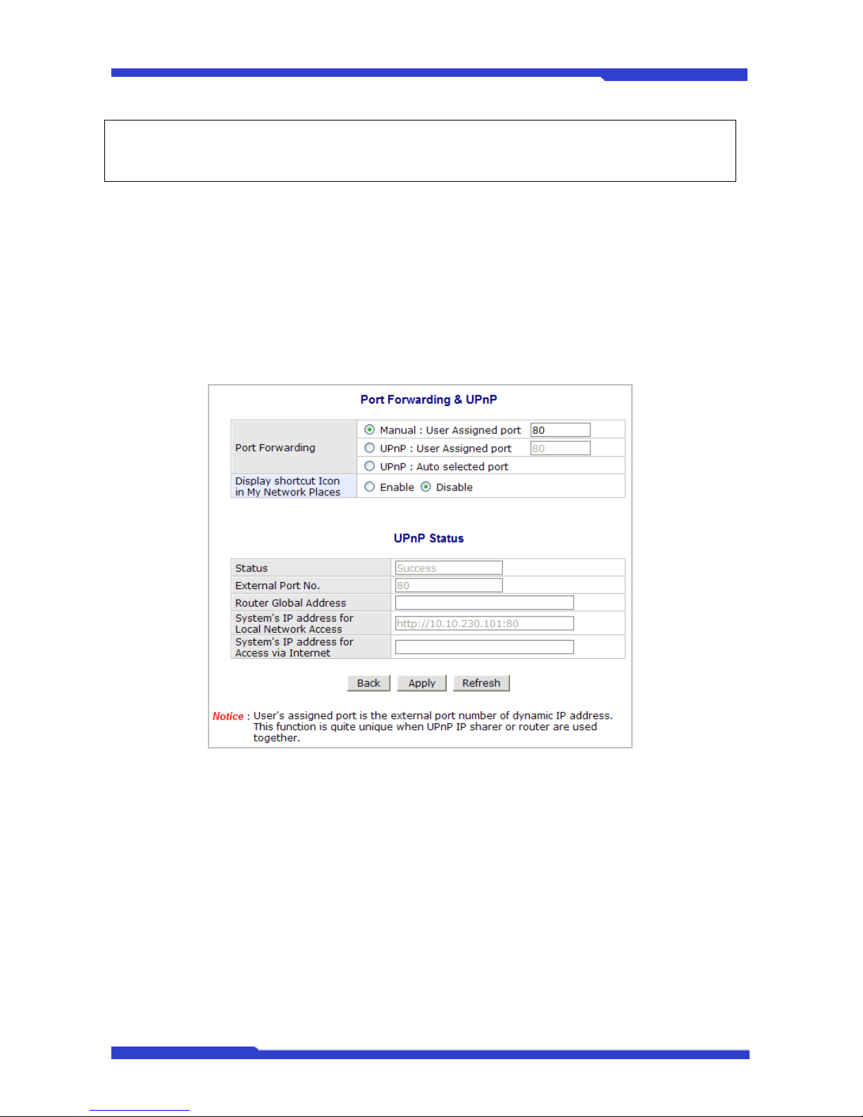
DNC(Dmax Network Camera) User’s Manual Part 3
DNC 27 Dongyang Unitech Co., Ltd
) Refer to CCTVHOME DNS
™
user’s manual for further details of CCTVHOME DNS™
Configuration.
9 Click Confirm button to check if your server is successfully registered in
CCTVHOME DNS™. You will find the URL address of your DNC server.
4.8. Port Forwarding & UPnP
UPnP (Universal Plug and Play) is a set of network protocols that enables discovering and
configuring local devices automatically. In terms of functionality, UPnP is divided into CP and Device
functions; Device function is for informing a network environment of its location as NVS, while CP is for
requesting a router for Port Forwarding service. (The router is also another UPnP device present in the
local network)
In the picture shown above, “Display shortcut Icon in My Network Places” part in the upper
table is for the Device function, and “Port Forwarding” part is for CP function.
Device function can be enabled regardless of the neighboring network devices (such as PC or
routers). For Microsoft Windows, this function has been supported since XP version and CP function can
be automatically enabled to use Port Forwarding service if the router supports UPnP device functionality.
In case of the router not following the standard or UPnP function unsupported, users have to
access the router to manually configure Port Forwarding and register a port. You can select the manual
mode by selecting Manual: User Assigned Port.
If the router supports UPnP Device function and you want to allocate a specific port for Port
Forwarding function, you are to select UPnP: User Assigned Port. On the contrary, if you’d like to
configure UPnP in a fully automatic manner, you can select UPnP: Auto Selected Port.
Page 76
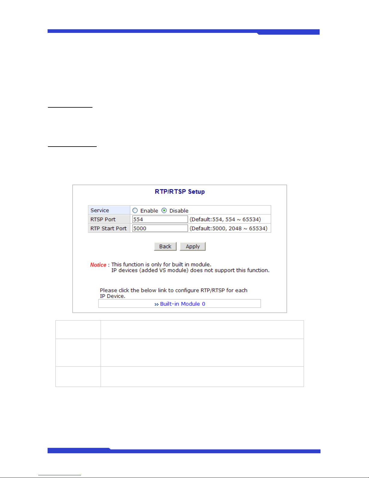
DNC(Dmax Network Camera) User’s Manual Part 3
DNC 28 Dongyang Unitech Co., Ltd
4.9. RTP/RTSP Setup
RTSP (Real-Time Streaming Protocol) is a protocol to transfer video and audio stream over the
network. Any application supporting Standard RTSP can be used for DNC server. Quick Time Player or
VLC program can be used for this, but it may not be supported in the environment within firewall. There
are two types of usage, one for Unicast address condition and the other for Multicast address condition.
Unicast Address
:
For Unicast address, use “rtsp://network video server ip address/cam0_0”. If there are multiple
channels, use cam0_x, x (0~3) with each number applied. If there are multiple modules, use camx_0 x (0
~ 3) with each module number applied.
Multicast Address
:
For Multicast address, use “rtsp://network video server ip address/mcam0_0”. If there are multiple
channels, use mcam0_x, x (0~3) with each channel number applied. If there are multiple modules, use
mcamx_0 x (0 ~ 3) with each module number applied.
Service
Enable: Start RTSP service
Disable: Stop RTSP service
RTSP Port
In normal case, use default port number 554 to connect to RTSP service. If
not using port 554, enter the port number you want to use.
e.g.) port number 445==> rtsp:// network video server ip address:445/cam0_0
RTP Start Port
The starting number of the port for video transfer. Each time video transfer
connection is made, the port number also increases.
Page 77
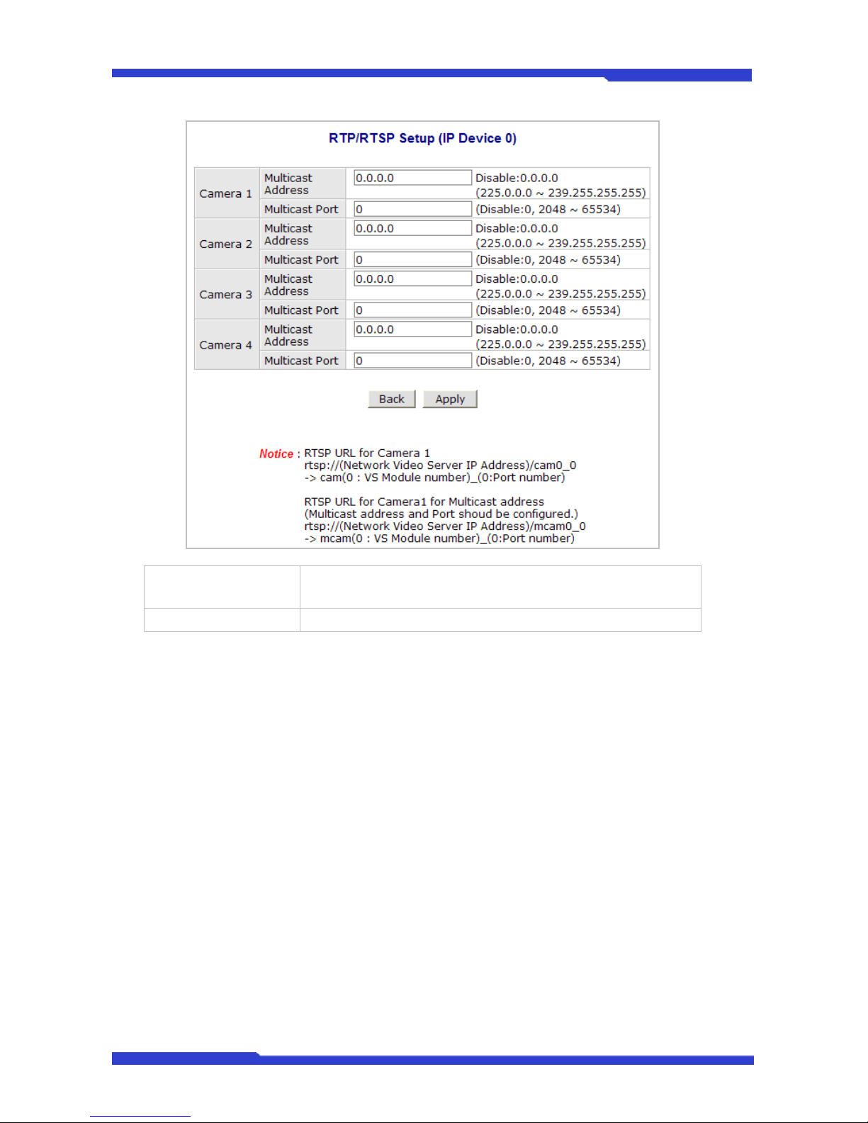
DNC(Dmax Network Camera) User’s Manual Part 3
DNC 29 Dongyang Unitech Co., Ltd
Multicast Address
Address for multicast video transfer
The multicast address 0.0.0.0 is for stopping multicast.
Multicast Port Port number for viewing the video with a multicast address
Page 78
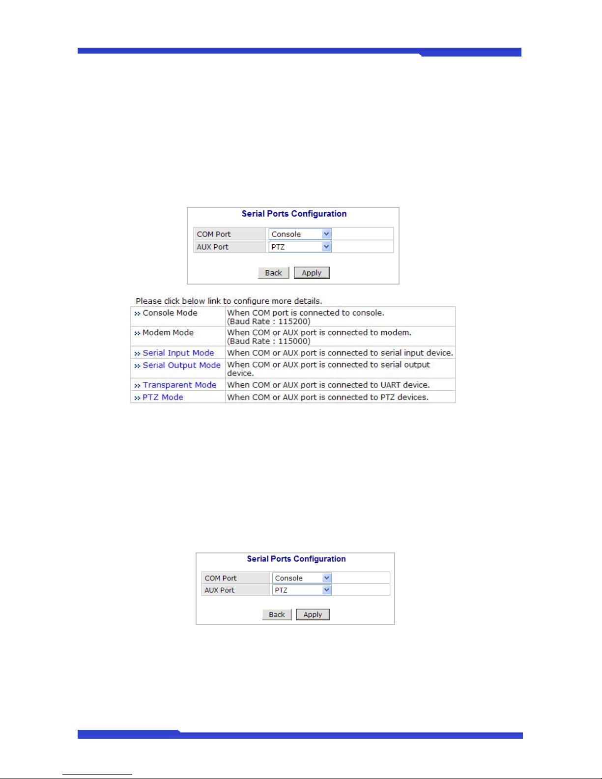
DNC(Dmax Network Camera) User’s Manual Part 3
DNC 30 Dongyang Unitech Co., Ltd
5. Device Configuration
You set up the connection between DNC® Server and the camera in this part of configuration. That
includes Video data, external devices, Input / Output, Alarm control, and etc.
5.1. Serial Ports
There are two serial ports configurable in the system, COM and AUX. COM port is primarily used
for console, and AUX is for PTZ control, but they both can be used for other purposes when necessary.
5.1.1. Serial Input Mode
When serial ports are in Serial Input Mode, DNC® Server can be triggered by the external
sensors to send images from the camera by email, or FTP. It can also activate Alarm Output by input
from sensors inputs. For example in a real life, if a dam’s water level comes to a pre-defined value, the
server can send the images of the dam’s water level meter from cameras. Another example is, when a
car running on highway exceed the speed limit, it can send the picture of the car.
To configure, click Serial Ports on Device Configuration. In COM Port or AUX Port, select Serial
Input and click Apply button to apply the change. The system will reboot then.
After rebooting is done, open the Serial Ports window in Device Configuration menu again.
Select the Serial Input Mode, then the Serial Input Mode Configuration windows will be displayed as
shown below.
Page 79
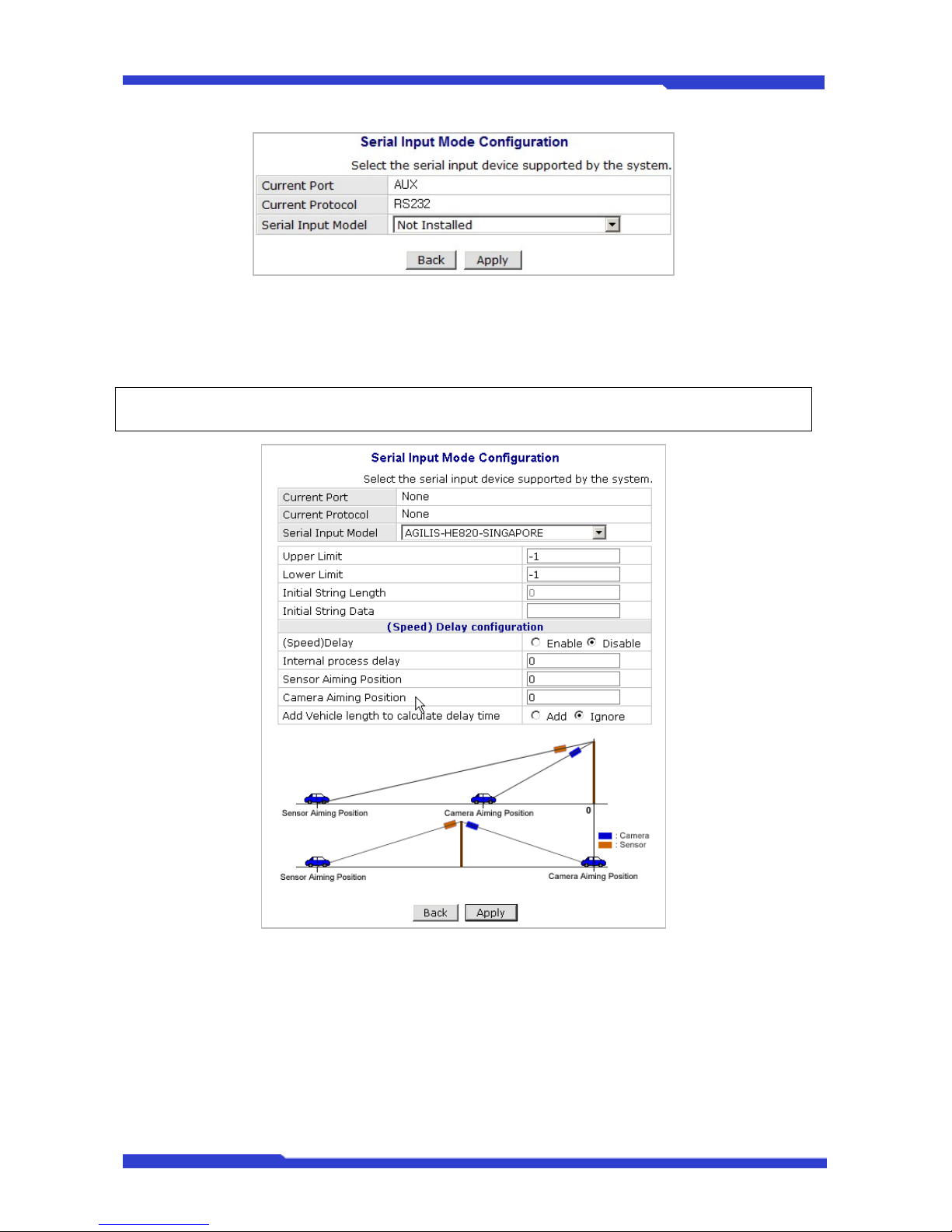
DNC(Dmax Network Camera) User’s Manual Part 3
DNC 31 Dongyang Unitech Co., Ltd
• Current Port: This shows the name of the port currently configured.
• Current Protocol: This shows the protocol being used. (only RS-232 can be displayed)
• Serial Input Model: You can select the sensor’s model number to use for Serial Input
The following example is when a speed sensor, AGILIS-HE820-SINGAPORE, is selected.
) If additional sensors need to be added, it will require installation of the device drivers.
• Upper Limit: The highest value in the range to assign
• Lower Limit: The lowest value in the range to assign
• Initial String Length: The length of initial string from sensor
• Initial String Data: The initial string from sensor
• (Speed) Delay: select Enable if sensor input needs delay
• Internal process delay: The amount of delay for sensor input
• Sensor Aiming Position: The position for sensor to aim
• Camera Aiming Position: The position for camera to aim
• Add Vehicle length to calculate delay time: The length of vehicle for applying delay time
Page 80
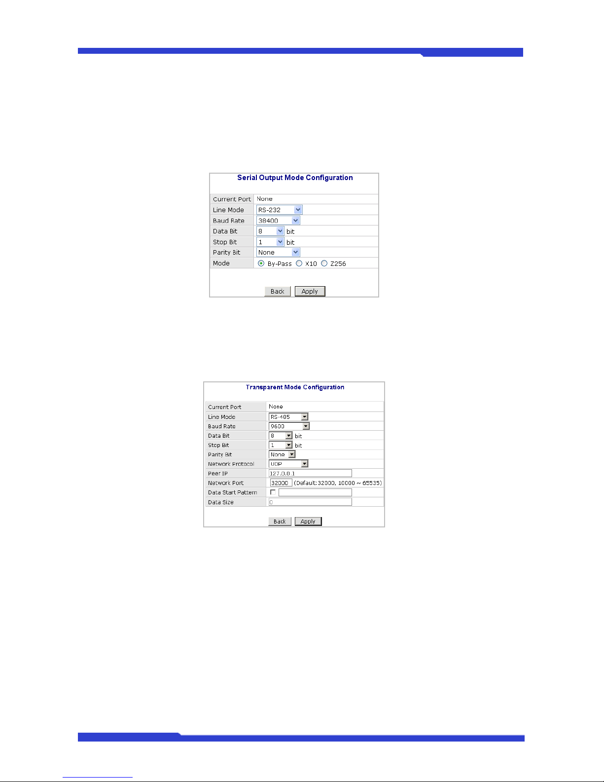
DNC(Dmax Network Camera) User’s Manual Part 3
DNC 32 Dongyang Unitech Co., Ltd
5.1.2. Serial Output Mode
Using Serial Output Mode, you can send UART device commands to DNC® Server in order to
control PTZ devices, Multiplexer, Access control box, X10 Protocol, z256 protocol by RS-232 or RS485/422 communication. In the picture below, serial output mode can be selected among By-Pass, X10,
or Z256.
5.1.3. Transparent Mode
When there are two DNC Servers present on the network, they can act like a transparent interface
between two different UART devices so that the communication between the UART devices can be
made transparently without a flaw.
• Line Mode: The type of communication protocol
• Baud Rate: Data transfer rate
• Data Bit: The number of bits in data
• Stop Bit: The number of stop bit
• Parity Bit: Parity bit characteristic
• Network Protocol: The type of protocol used to send data
• Peer IP: IP address of other DNC server
• Network Port: Network port number of the server
• Data Start Pattern: Data start pattern (Not used if unchecked)
• Data Size: Data size in single transfer (Not used if unchecked)
Page 81
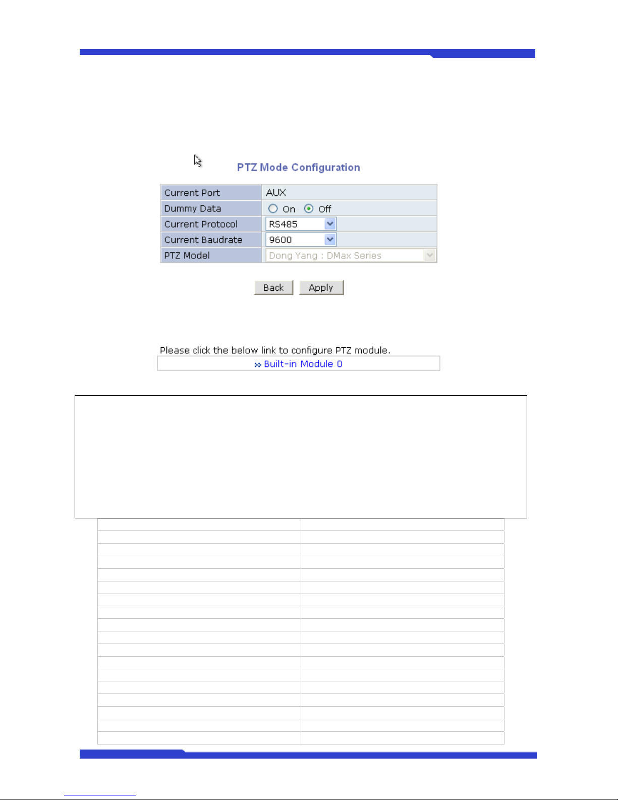
DNC(Dmax Network Camera) User’s Manual Part 3
DNC 33 Dongyang Unitech Co., Ltd
5.1.4. PTZ Mode
With the PTZ camera’s RS-485 cable wired to DNC® Server’s COM or AUX port, select the proper
PTZ model in PTZ Mode Configuration screen, then click Apply button to save the change.
) Before purchasing receivers or PTZ cameras, please contact Dongyang Unitech or distributor to
find out if the product’s protocol is supported by DNC server.
) When a PTZ model is selected from the list, Current Protocol and Current Baud rate will be set to
the default values. You can change them if required.
) The table below shows the PTZ protocols supported by DNC. (Currently 43 types of PTZ models
are supported and subject to change in the future.)
Dong Yang : DMax Series Dongyang Unitech Cameras
Pelco-D : Spectra Dome RNK : RNK-DOME
Pelco-P : Spectra Dome ERNITEC : BDR-510
Seyeon Tech : SRX-500/SPT-102 Inter-M : VSD-640/625L
Seyeon Tech : FSD-230/270 KODICOM : KRE-301
Seyeon Tech : FSD-301 FINE : CRR-1600I
ELMO : ELDOME Dongyang : DY-XXXX
SANTEC : Santec Dome Bosch : Auto Dome
Honeywell : HSDN-230/251(H) Sungjin : SJ2000/3000RX
Honeywell : HSDN-251(P) Honeywell : HRX-2000
SAMSUNG : SCC641/643A Inter-M : VRX-2201
SAMSUNG : SCC641/643A(RS422) LG : Speed Dome
SAMSUNG : MRX-1000 Lilin PIH-7000 Dome
VICON : V-1311RB Yujin YRX-5000S(Pelco-D)
VICON : Surveyor-1000/2000 INTPLUS : Pelco-P PTZ 1
SAMSUNG Techwin : SPD1600 VICON : V-1311RB-600
SAMSUNG Techwin : SRX-100B Pelco-D : SK-D106
SAMSUNG Techwin : SRX-100R Pelco-D : YuJin
Page 82
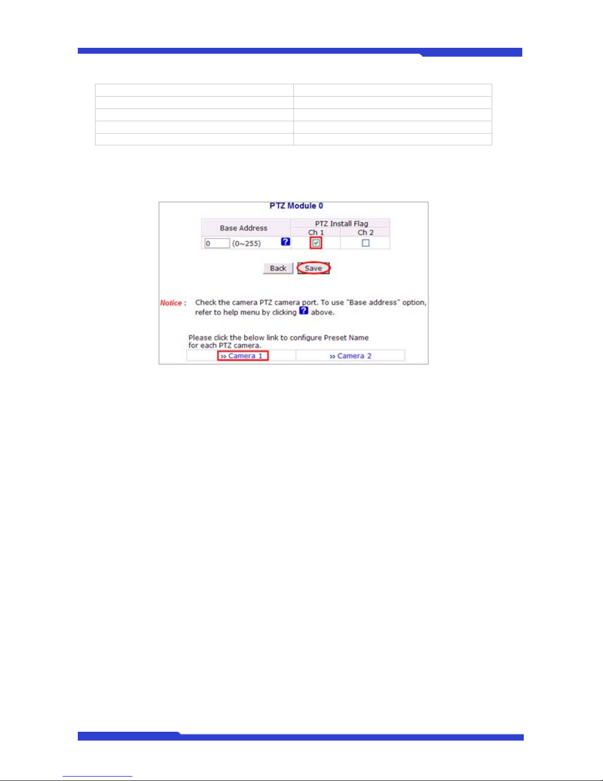
DNC(Dmax Network Camera) User’s Manual Part 3
DNC 34 Dongyang Unitech Co., Ltd
American Dynamics : DELTA DOME Pelco -D-AUX : HUVIRON
KALATEL : CYBER DOME(KTA-xxxx) Pelco-P-AUX : ONE KING
Panasonic : WV-CS854 Pelco-D-AUX : Probe
SONY : EVI-D30 Honeywell : HSDN-P 251(H)
CANON : VC-C4
1. After selecting the proper PTZ model, click Module 0 to activate the camera channel.
2. Base Address should be matched to the address of the PTZ camera or the receiver used
here. (Base Address = PTZ Camera’s Base Address – 1). For example, if PTZ camera’s
address is 1, then the base address becomes 0. You can find out the PTZ camera’s
address from its user’s manual.
3. After put a checkmark on the channel that is connected to PTZ camera or receiver, click
Save button to apply the change. The picture above is the example of PTZ camera wired
to Channel 1 only.
4. If the PTZ camera or receiver has a Preset function, click Camera 1 to configure the
Preset Name and the camera location. With Preset function, you can move the camera
directly to previously configured position promptly.
Page 83
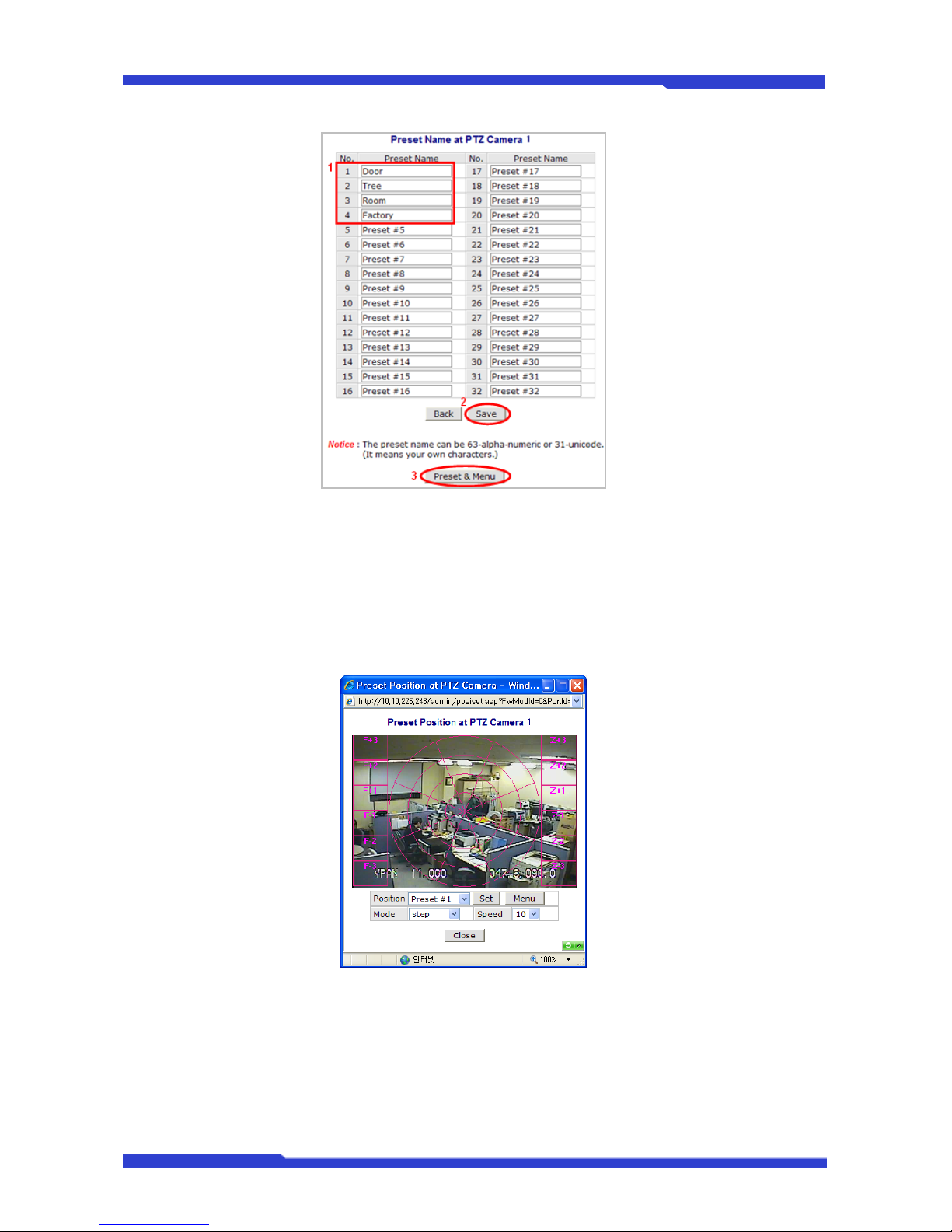
DNC(Dmax Network Camera) User’s Manual Part 3
DNC 35 Dongyang Unitech Co., Ltd
5. Up to 32 different Preset can be configured and saved. The picture above shows the
example of four different Presets made. After configuring Preset is done, click Save
button to take effect.
6. To preset the camera position, click Preset & Menu, then the video monitoring screen will
appear as shown below. Control the camera’s position as you desire, and click Set button.
7. After all the Preset items are set up, click Close button to exit the configuration.
5.1.5. PTZ Mode
These DNC Servers are Speed Dome models, which are all-in-one type network cameras and
don’t have PTZ configuration part. It’s possible to set Preset, Swing, Group, and Tour functionalities in
those servers and further detailed parts can be configured by use of OSD. Below is the steps for
configuration.
1. Click Devices Configuration > Serial Ports > PTZ Mode > Built-in Module 0 > Camera 1
Page 84
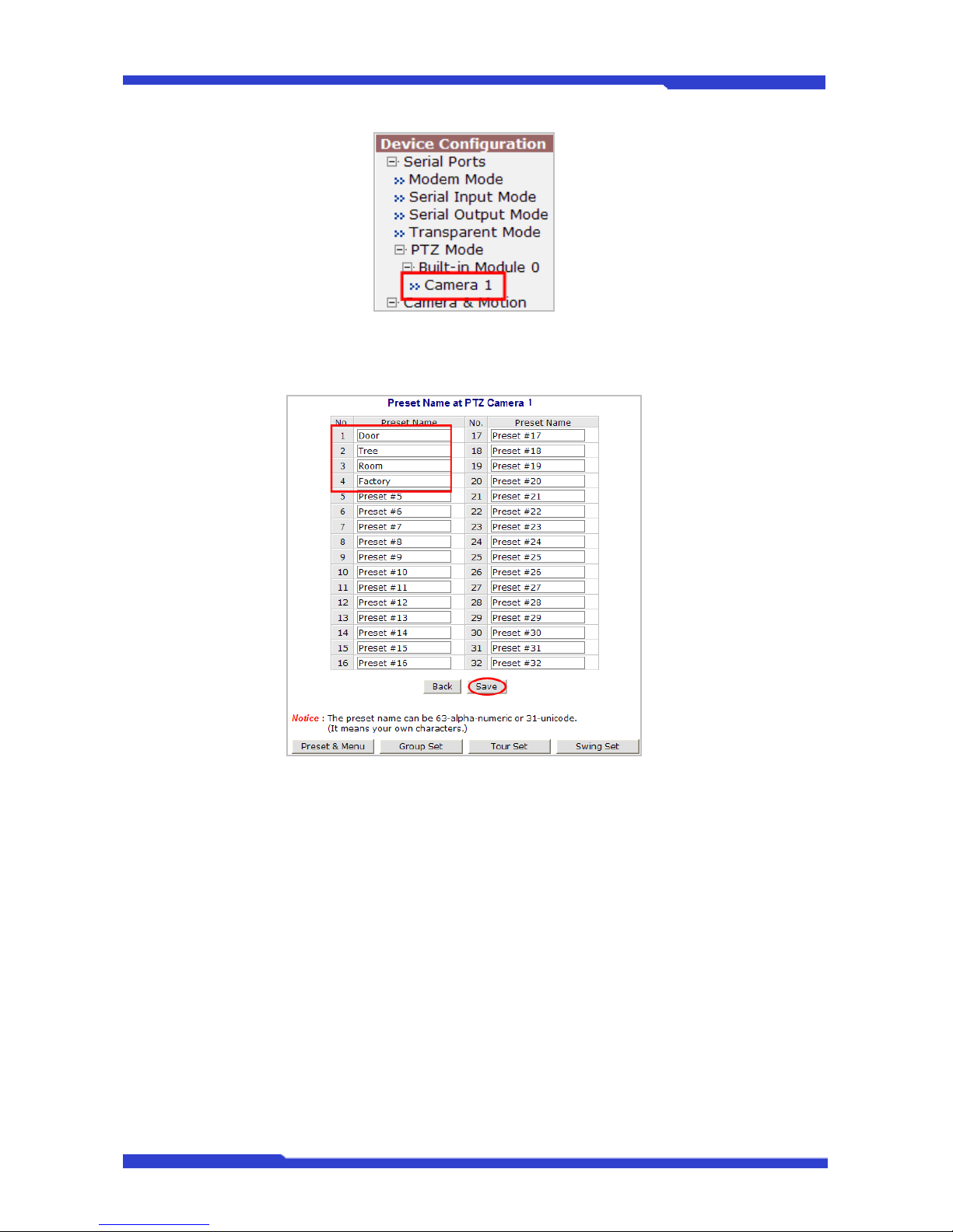
DNC(Dmax Network Camera) User’s Manual Part 3
DNC 36 Dongyang Unitech Co., Ltd
2. Enter the Preset names as required. You can make up to 32 Preset names. Below is the
example of entering 4 different room names.
3. Use the buttons to configure Preset, OSD, Swing, Group, and Tour. (Swing, Group, and
Tour)
Page 85
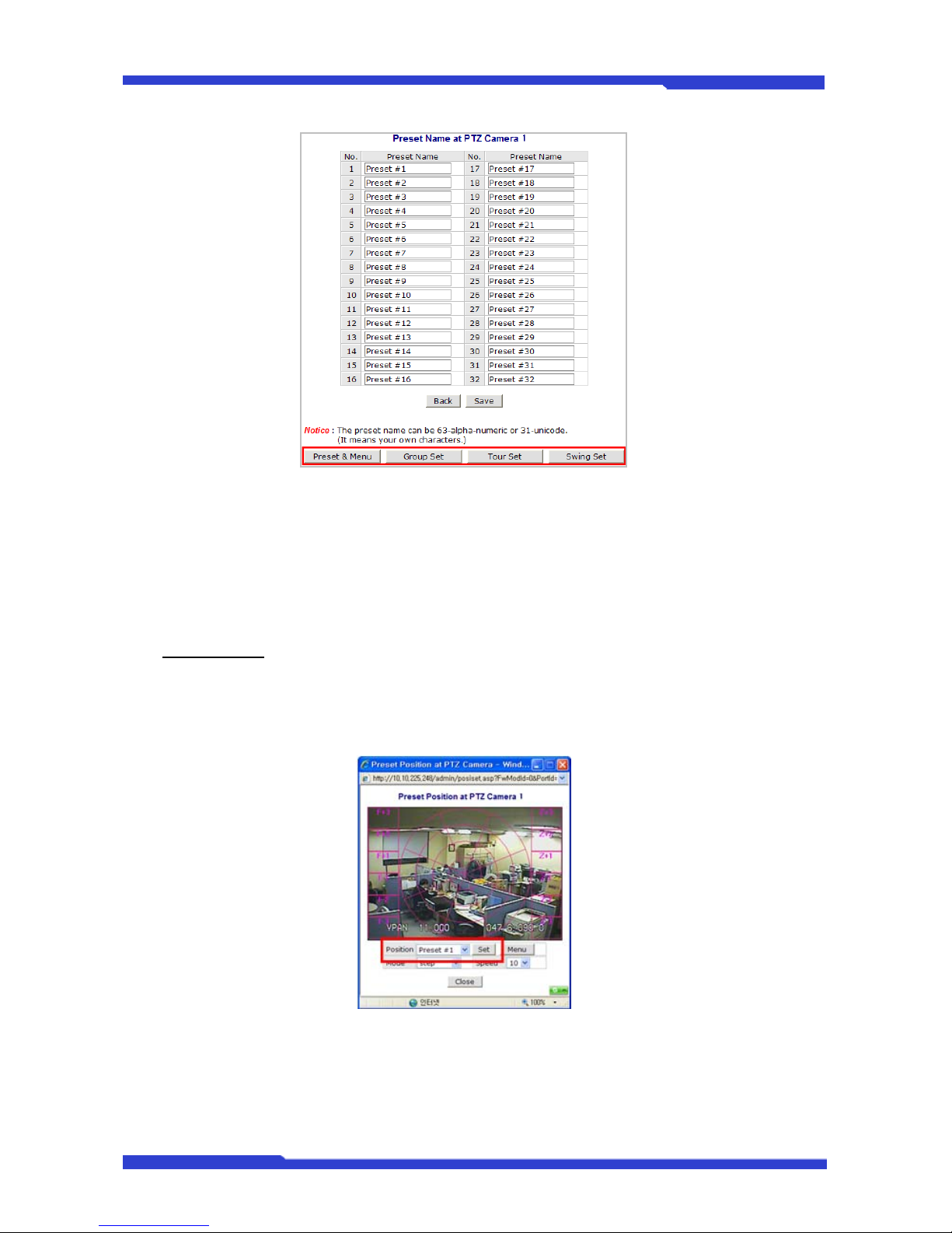
DNC(Dmax Network Camera) User’s Manual Part 3
DNC 37 Dongyang Unitech Co., Ltd
• Preset & Menu: You can pre-define the spot you want to see. Up to 32 settings can be
stored. Click Menu button to configure the camera’s attributes.
• Swing: Repeat moving between two positions in certain period.
• Group: Each group moves around up to 6 pre-defined positions in certain period.
• Tour: Move around up to 6 different groups in certain period.
Preset & Menu
Click on the button and it will display the video window as shown below. Use PTZ to control the
camera to show the desired spot. Select the Preset number you’d like to assign to it. Click Set
button to save the preset values in the Preset number.
• Mode: When Step is selected, it will move as much as pre-defined distance. When
Continuous is selected, it will keep moving as long as the button is being pressed.
• Speed: In Step mode, different Speed value is different Step size. In Continuous mode, it
is different moving speed.
Click on Menu button, and it will display an OSD window for adjusting camera attributes. OSD
Page 86
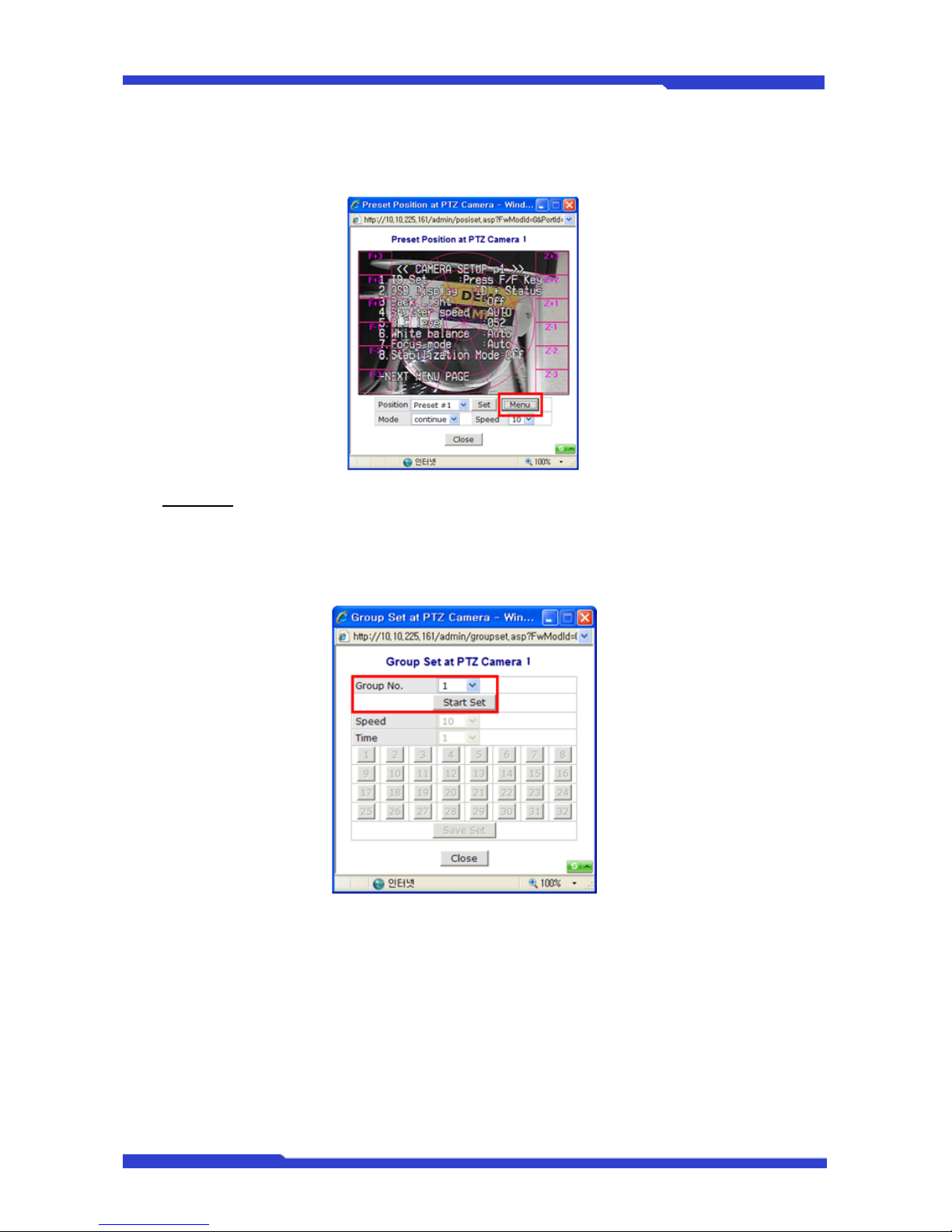
DNC(Dmax Network Camera) User’s Manual Part 3
DNC 38 Dongyang Unitech Co., Ltd
setting can be made by Up, Down, Left, Right arrow keys. After setting is finished, click Menu
button.
Group Set
Click the button and it will display the Group setting window as shown below. Select a group
number as you’d like, and click Start Set button. Preset numbers from 1 to 32 will become active
for the group.
Speed: How fast it will move between Preset items when Group function is executed.
Time: How long it will stay at the Preset. Each Group can have up to 6 Presets.
Page 87
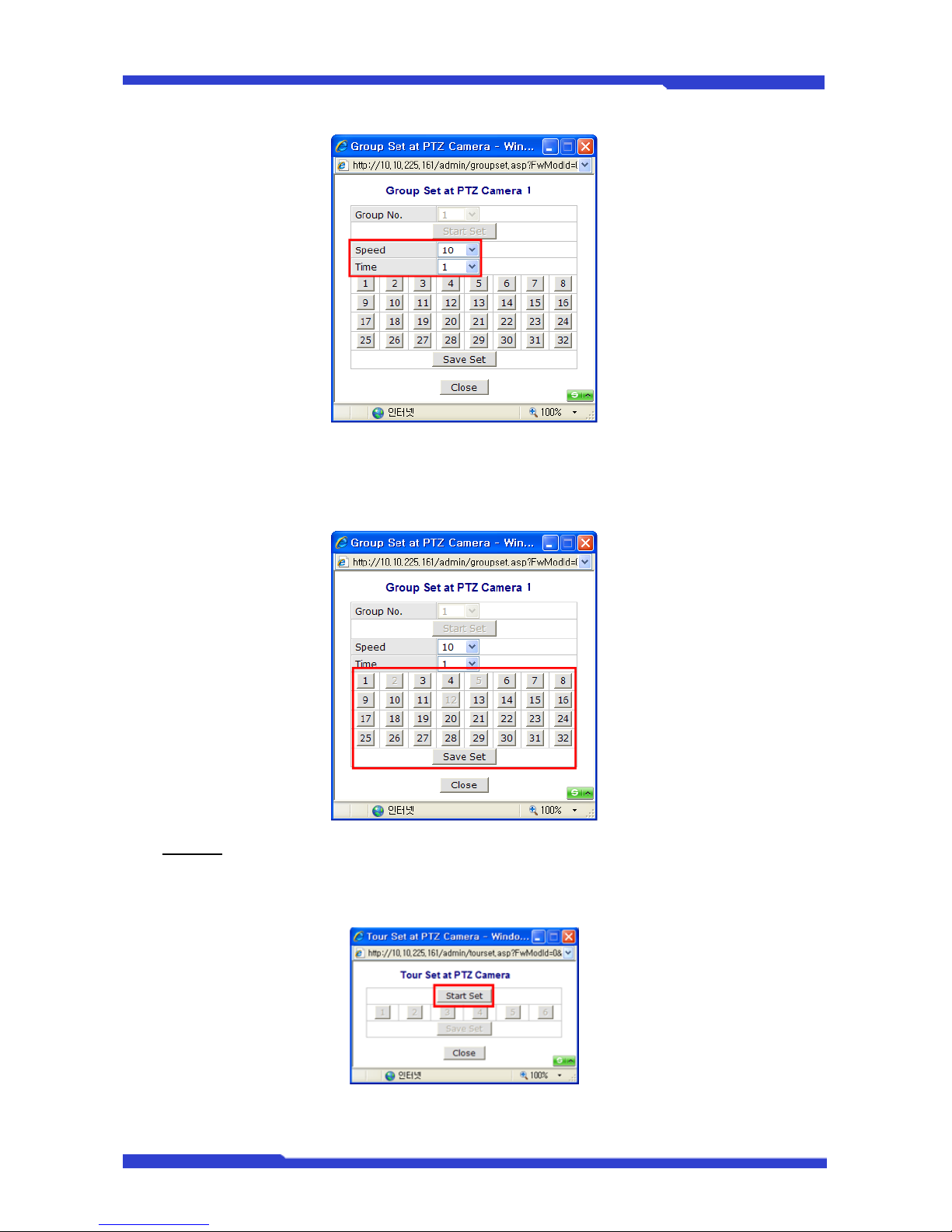
DNC(Dmax Network Camera) User’s Manual Part 3
DNC 39 Dongyang Unitech Co., Ltd
After Preset is configured, click Save Set button. Group setup window will be displayed. You can
configure up to 6 groups. The usage of Group can be controlled at PTZ Control window in Smart
Viewer.
Tour Set
Click the button and it will display the Tour Set window. Up to 6 groups can be combined to run in
Tour mode.
Select a Group number as desired, then click Save Set button to finish setup. The usage of Tour
can be controlled at PTZ Control window in Smart Viewer.
Page 88
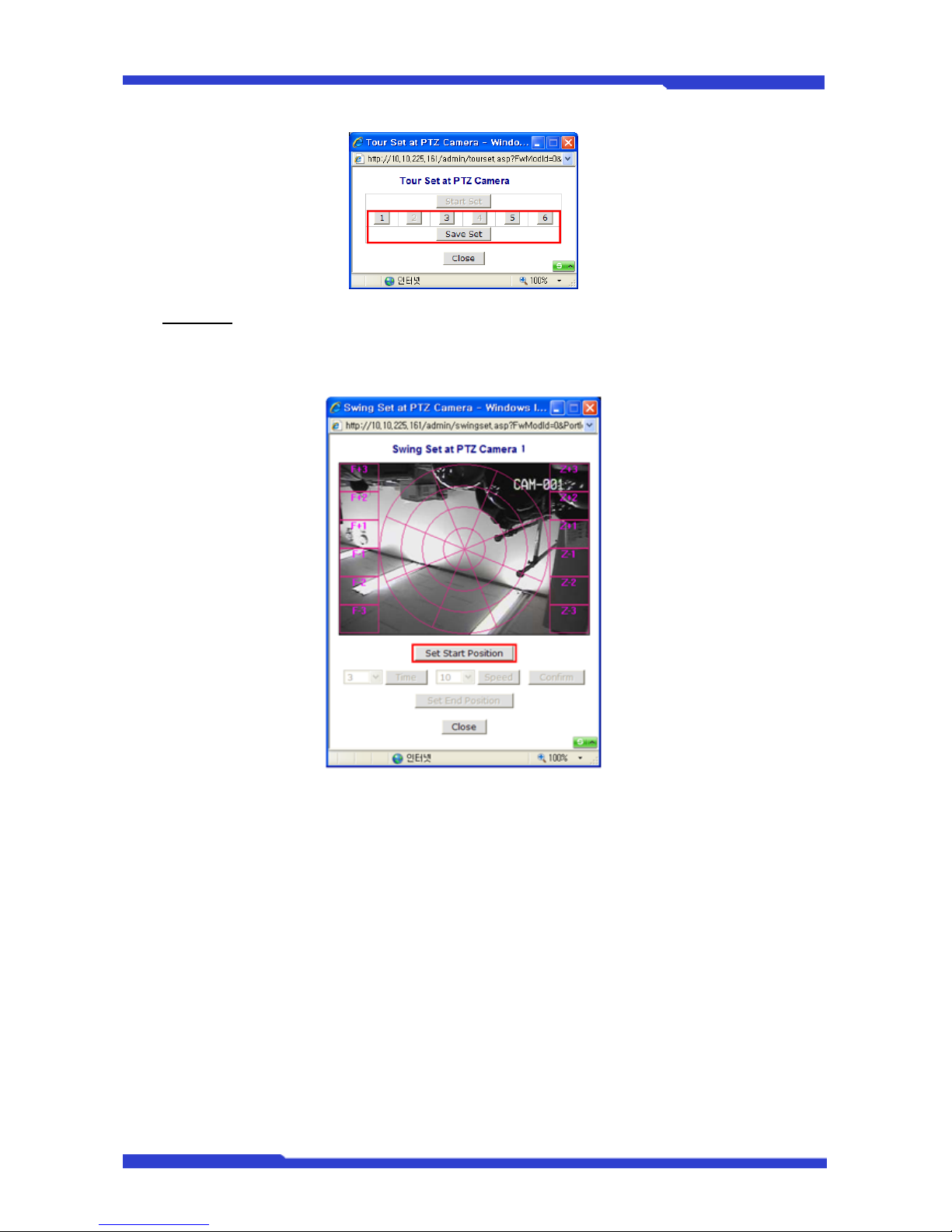
DNC(Dmax Network Camera) User’s Manual Part 3
DNC 40 Dongyang Unitech Co., Ltd
Swing Set
Click the button and it will display the Swing Set window. Use PTZ to direct the camera to put the
desired spot on the center of the camera viewing area, then click Set Start Position button.
Select the start position and the waiting period, then click Time button.
Page 89
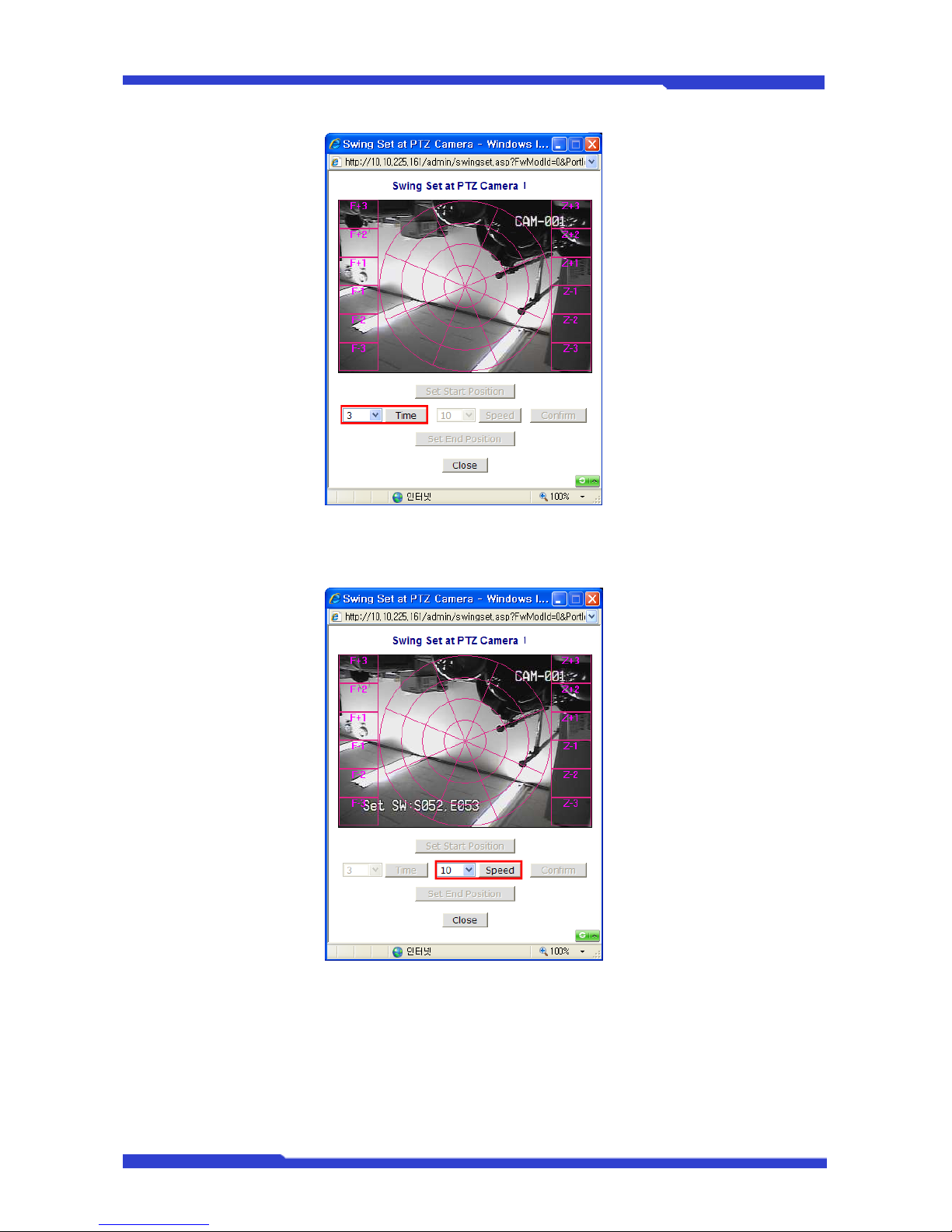
DNC(Dmax Network Camera) User’s Manual Part 3
DNC 41 Dongyang Unitech Co., Ltd
Select the moving speed between the starting position and the ending position, then click Speed
button.
Click Confirm button.
Page 90
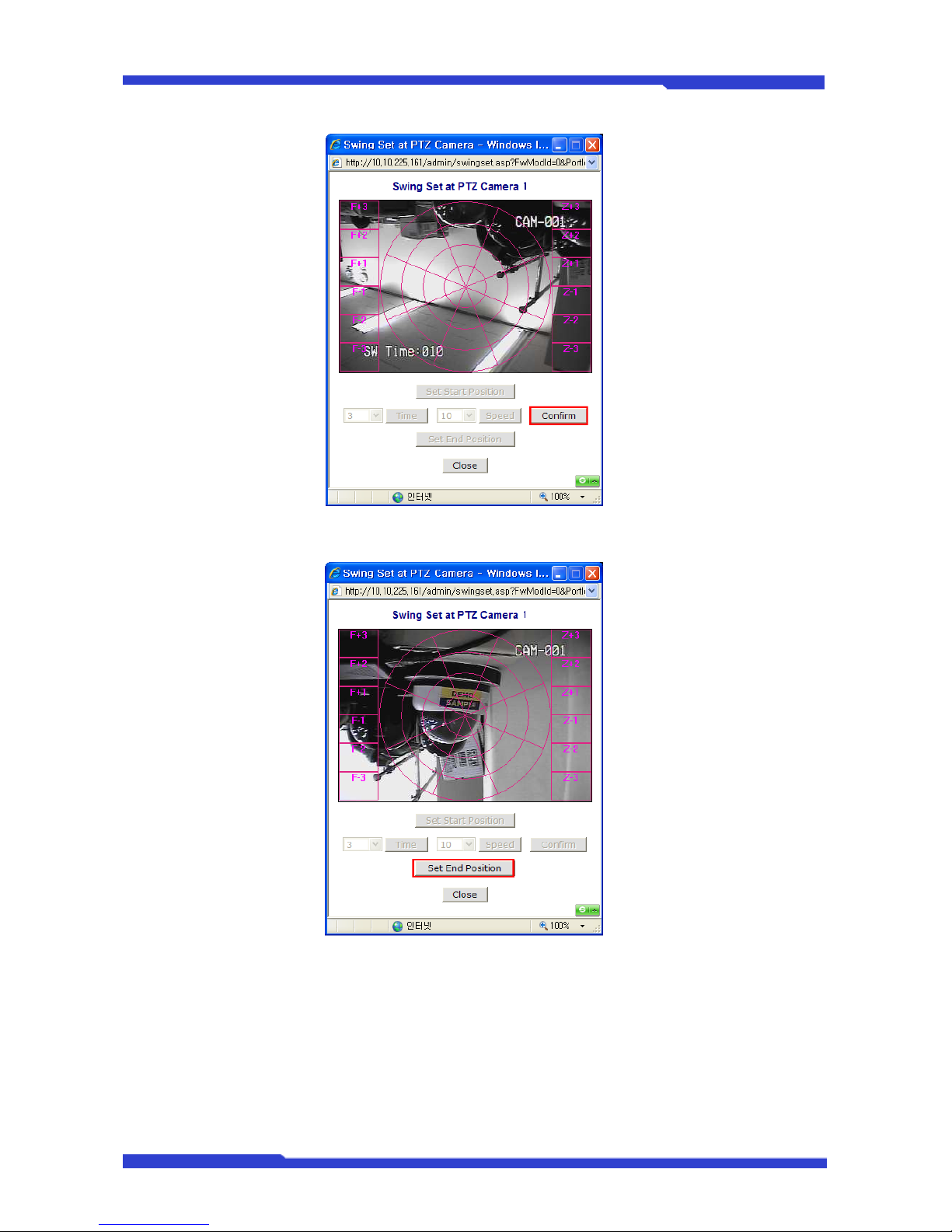
DNC(Dmax Network Camera) User’s Manual Part 3
DNC 42 Dongyang Unitech Co., Ltd
Now use PTZ to move to the ending position, and then click Set End Position.
The control of Swing function can be made at PTZ Control window in Smart Viewer.
5.2. Camera & Motion
You are to configure what data will be combined with video data, and set up specific operating
environment for each channel. (A Channel means a camera which is directly wired to DNC® Server
Cameras or remotely connected over the network)
Page 91
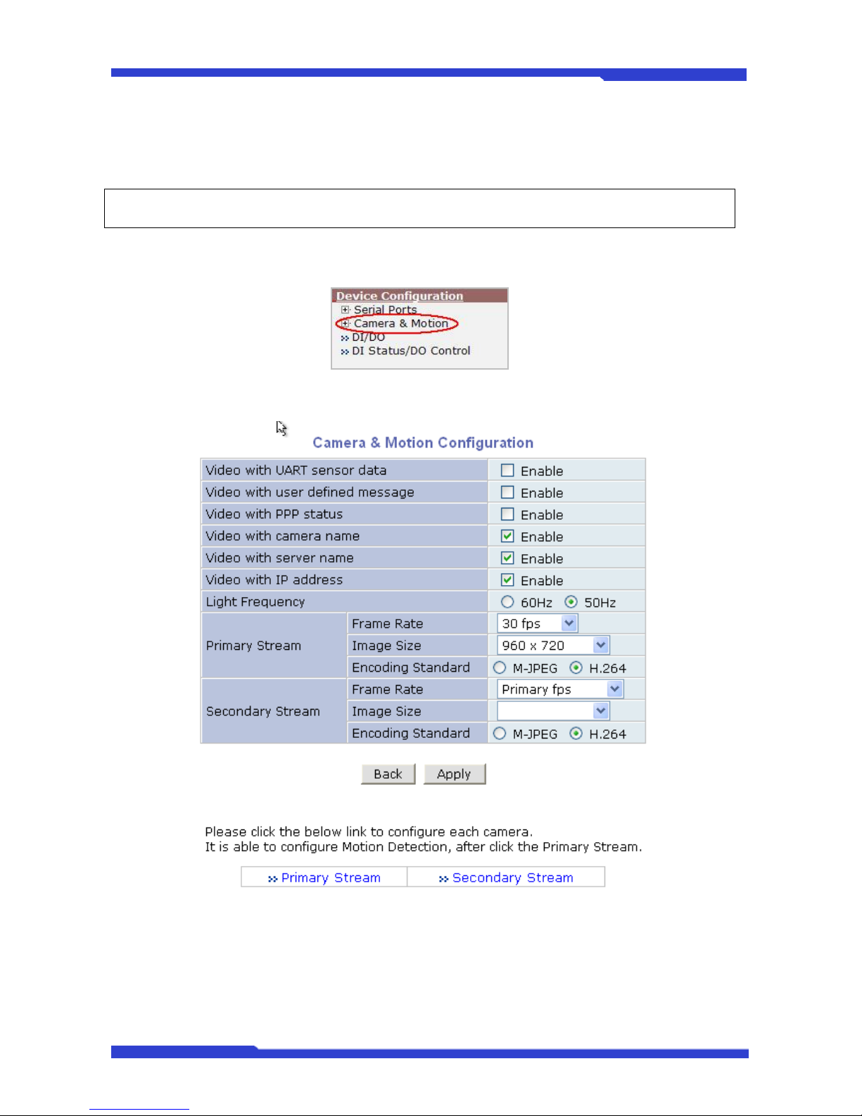
DNC(Dmax Network Camera) User’s Manual Part 3
DNC 43 Dongyang Unitech Co., Ltd
5.2.1. Camera & Motion
This menu is used to set up the selection of video format, data added to video data, encoding
speed, audio control, image resolution, video quality, motion detection, and etc.
) For Dual Stream products, the most of parameters are dependent on primary stream value.
1. Click Device Camera & Motion on Device Configuration menu.
2. Configure the video data format and other information to be contained in it.
• Default Video Format: Video transmitting format of the camera attached to DNC Server. Select
from NTSC or PAL.
• Video with UART sensor Data: If Enabled, video data will contain UART sensor data from
COM port.
• Video with user defined message: If Enabled, video data will contain the user-defined data.
(Reserved Field)
Page 92
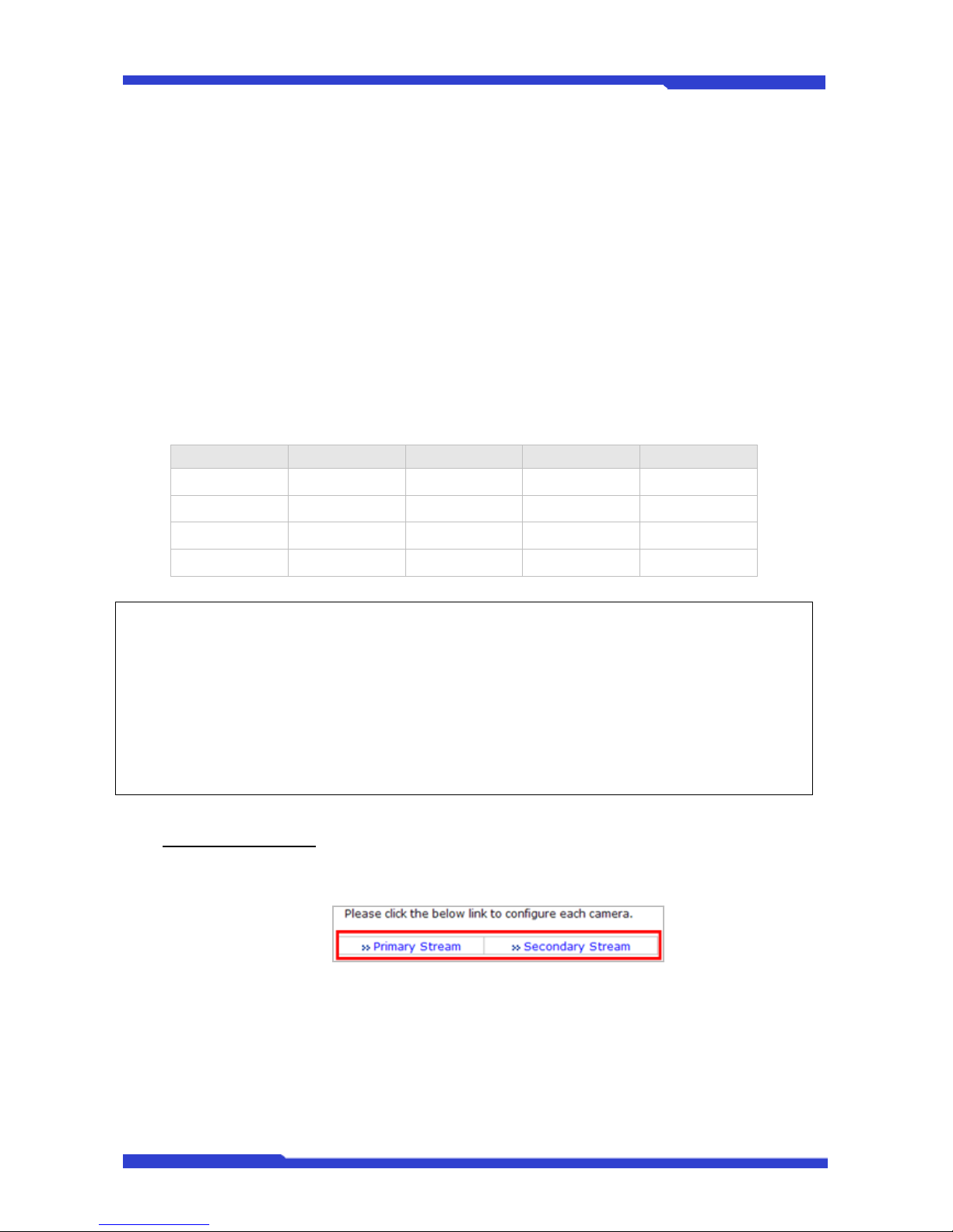
DNC(Dmax Network Camera) User’s Manual Part 3
DNC 44 Dongyang Unitech Co., Ltd
• Video with PPP status: If Enabled, video data will contain PPP connection status.
• Video with camera name: If Enabled, video data will contain the camera name.
• Video with server name: If Enabled, video data will contain the server name that you defined.
• Video with IP address: If Enabled, video data will contain the IP address of the video server.
• Light Frequency: Used for Flickering Rejection. Select the electric power frequency used in the
region, either 50 or 60Hz.
• Frame Rate: For Primary Stream, this is the number of frames compressed in every second.
You can control the network traffic with this parameter. For Secondary Stream, it can be set to
manner of 1/2, 1/4, 1/8... of the primary stream.
• Image Size: Select the resolution of each channel’s video
• Encoding Standard: Select the compression method of each video, either M-JPEG or H.264
format. It is not allowed to set both channels to M-JPEG.
Below is the table of images sizes.
Video Format SXGA D1 CIF QCIF
NTSC - 704 x 480 352 x 240 160 x 112
PAL - 704 x 576 352 x 288 160 x 144
VGA - 640 x 480 320 x 240 160 x 112
1.3M Pixel 1280 x 1024 640 x 480 320 x 240 160 x 112
) M-JPEG: This format requires much higher network bandwidth than H.264 compression. But
because of its higher quality of still image, it is adequate for detailed reviewing of stored video.
) H.264: In this format, each frame data is related to other nearby frames. For this reason, it
provides much higher compression ratio than M-JPEG and is adequate for video transfer. However,
if network condition is not very good and having dropped frames in video data, the video quality can
be relatively low. With DNC server, you can set the number of P-frames in the video which is
independent still images between I-frames.
3. To save the setting, click Apply button.
Camera Configuration
On the lower part of Camera & Motion Configuration menu, select a channel you want to
configure.
In the example shown below, Primary Stream is set to M-JPEG, and Secondary Stream set to
H.264 for compression format. Enter detailed parameters of the camera selected here.
Page 93
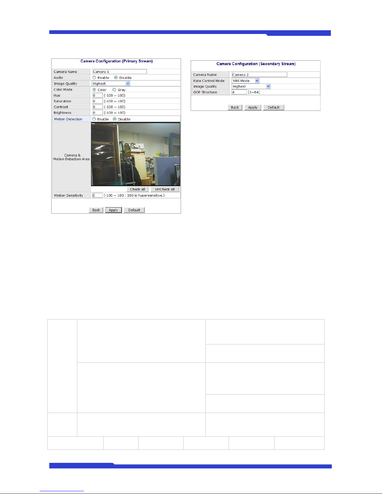
DNC(Dmax Network Camera) User’s Manual Part 3
DNC 45 Dongyang Unitech Co., Ltd
Primary Stream (M-JPEG)
Secondary Stream (H.264)
• When the image sensor is VGA CMOS/CCD or 1.3M CMOS/CCD, there will be no Hue,
Saturation, Contrast, or Brightness setting items shown. Only with NTSC or PAL will those
parameters be configured.
• Camera Name: Enter the name of the channel in up to 21 alphanumeric or up to 10 Unicode
characters.
• Audio: Select if Audio function is to be used (applies to Primary Stream only)
9 DNC® Server provides 2-way audio streaming by combining microphone input with video data.
Users can listen to the streamed audio on PC speakers.
• Image Quality Setup
MPEG-4
/ H.264
Rate Control Mode: VBR (Variable Bit Rate)
Video frames are encoded with selected image
quality and GOP. Encoded frames have
different data size from each other.
Image Quality: one of 6 quality levels
(Low Compression / Highest / High
Normal / Low / Lowest)
GOP Structure: Distance between IFrames. That is filled with P-frames.
Rate Control Mode: CBR (Constant Bit Rate)
Video frames are encoded with selected image
quality and GOP. Encoded frames have the
same data size as other frames. Due to the
constant bit rate, it has better stable
transmission performance.
Bit Rate Control: Total number of Bits
encoded per second. The higher Bit Rate,
the better image quality. Can be set
between 32kbps and 2Mbps.
GOP: Distance between I-Frames. That is
filled with P-frames.
M-JPEG -
Image Quality: one of 6 quality levels
(Low Compression / Highest / High
Normal / Low / Lowest)
Low Compression Highest High Normal Low Lowest
9 In Image quality level setup, selecting the left results in higher image quality, but requires higher
Page 94
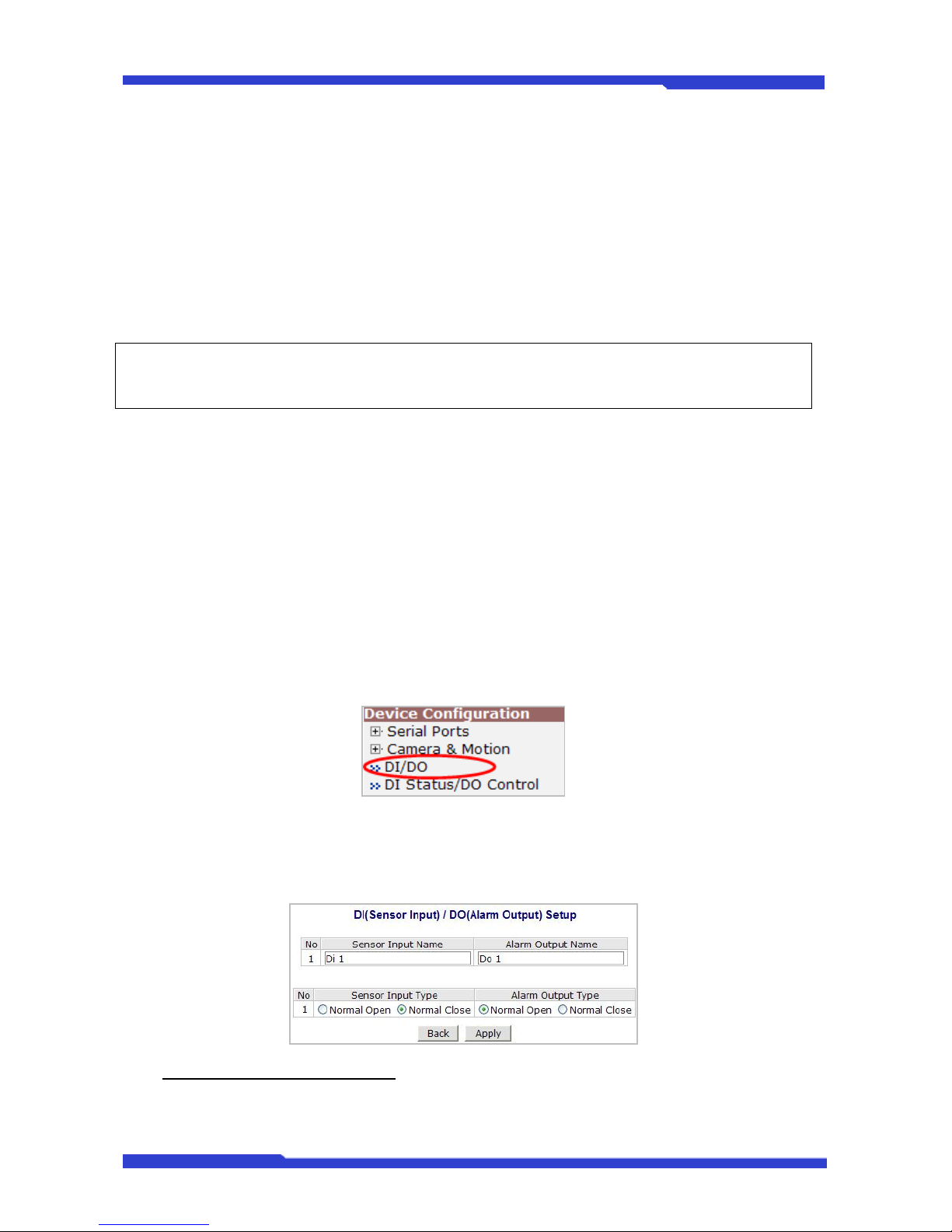
DNC(Dmax Network Camera) User’s Manual Part 3
DNC 46 Dongyang Unitech Co., Ltd
network bandwidth. Selecting the right requires lower network bandwidth, but gives decreased image
quality.
• Color Mode: Select either Color or Gray (applicable to Primary Stream only)
• Hue: Set the color of image between -100 and 100 (applicable to Primary Stream only)
• Saturation: Set the intensity of the image between -100 and 100 (applicable to Primary
Stream only)
• Contrast: Set the contrast of the image between -100 and 100 (applicable to Primary
Stream only)
• Brightness: Set the brightness of the image between -100 and 100 (applicable to Primary
Stream only)
) Color Mode, Hue, Saturation, Contrast, Brightness items are displayed only when the input video
signal is NTSC or PAL.
• Motion Sensitivity: This value sets how sensitively the motion detection works for the
motion detection functionality. It can be between –100 and 100 while 100 is the most
sensitive.
• Motion Detection: This decided whether the Motion Detection is to be used. If Enable is
selected, you can set which part of the camera image the Motion Detection does
functioning. This only works in Primary Stream mode.
After configuration is finished, click Apply button to save the setting. If you click Default button, the
entire configuration will be reset to the original values.
5.3. DI (Sensor Input) / DO (Alarm Output)
Select DI/DO from Device Configuration menu to configure Sensor Input and Alarm Output.
5.3.1. DI (Sensor Input) / DO (Alarm Output)
You can define Sensor Input Name and Alarm Output Name as you want, which should be up to
31 alphanumeric or up to 15 Unicode characters.
Sensor Input / Alarm Output Type
• Normal Open Type: Normal condition of this type is OPEN, and goes CLOSED when
triggered by an event.
Page 95
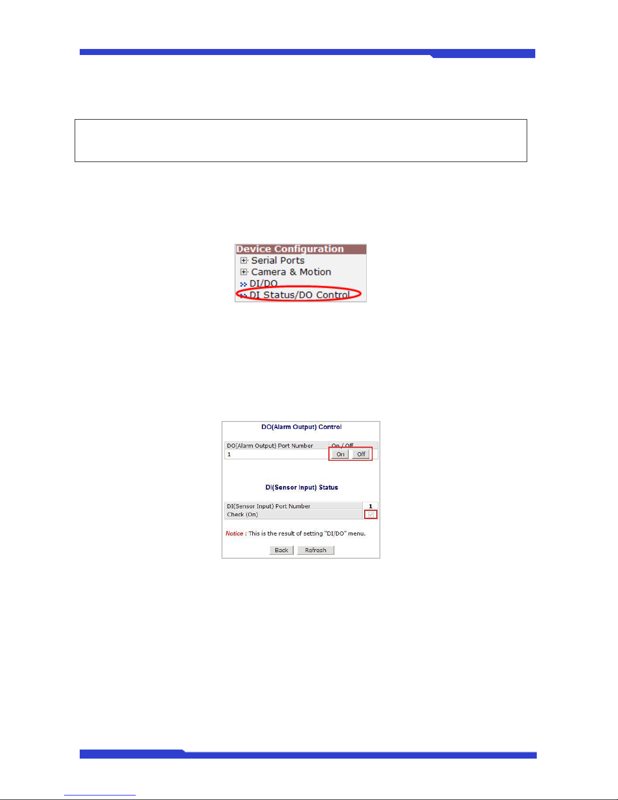
DNC(Dmax Network Camera) User’s Manual Part 3
DNC 47 Dongyang Unitech Co., Ltd
• Normal Close Type: Normal condition of this type is CLOSED, and goes OPEN when
triggered by an event.
) Make sure the type of the sensor and use it correctly to the type. If a Sensor Input is not used, it
must be set to Normal Open Type to avoid a false input.
5.4. DI Status/DO Control
Select DI Status/DO Control on Device Configuration menu to configure the behavior of those
Input and Output ports.
5.4.1. DI (Sensor Input) Status/DO (Alarm Output) Control
These DNC models have 1 Alarm output port and they act like a push button. When you click On
button, it is essentially like the push button pressed. When you click Off button, it is like the push button
not pressed.
The status of Sensor Input can be monitored through DI. When the checkbox is marked, that
means the Alarm is activated. When it’s not marked, then the Alarm is not activated.
6. Advanced Configuration
DNC can be configured to start and stop certain pre-defined services by scheduling, event, or
conditions. It also has the ISENS feature, which is a way of integrating DNC with CMS software. You can
set up the advanced services in Advanced Configuration menu.
There are two types of advanced service, one is Buffered Service and the other is Periodic
Service. In Buffering Service, a series of images continue to be stored in buffer memory of server for a
certain period amount of time. When the server is triggered by an event or schedule, the images or alarm
status right before and after the event/schedule are reported to you by email or buffered FTP services.
Page 96
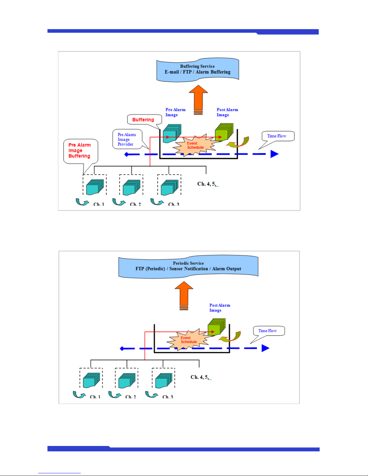
DNC(Dmax Network Camera) User’s Manual Part 3
DNC 48 Dongyang Unitech Co., Ltd
In Periodic Service, only the image, alarm/sensor status after an event/schedule is reported to you
upon the server is triggered.
6.1. Advanced Services
Pre-Alarm buffer size and buffering speed can be defined here.
Page 97
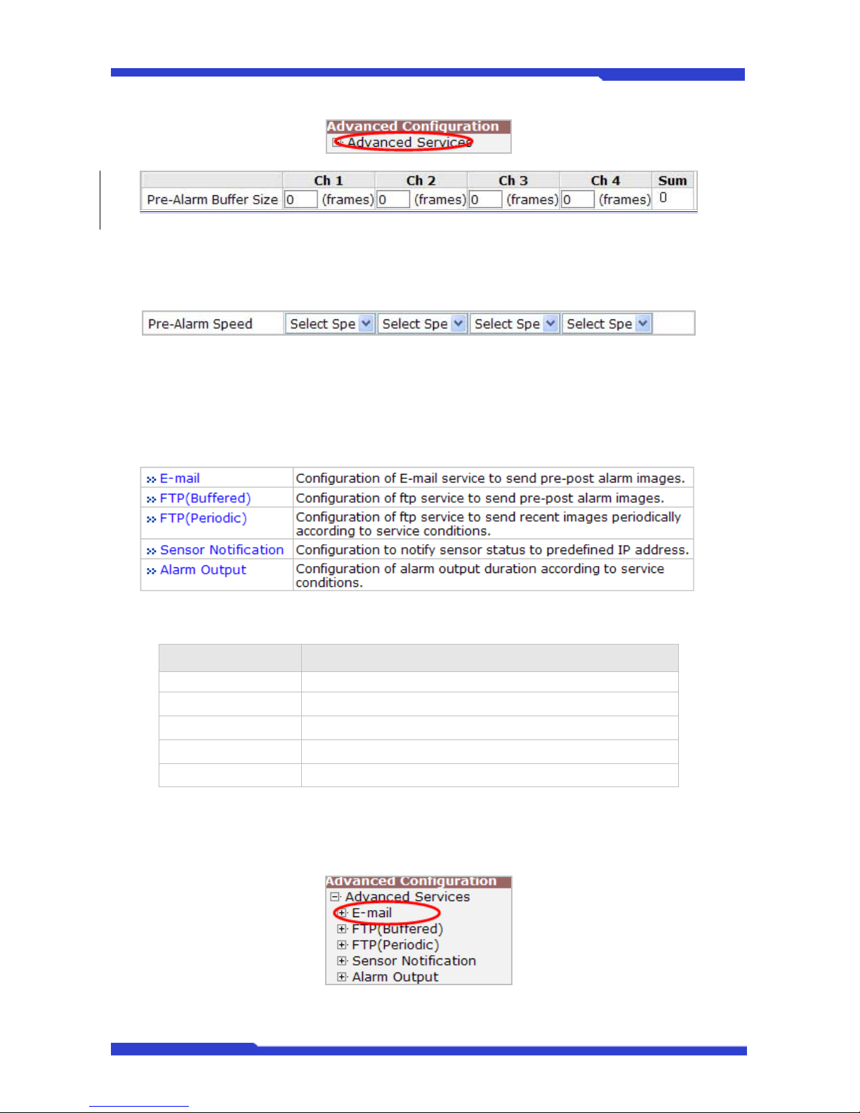
DNC(Dmax Network Camera) User’s Manual Part 3
DNC 49 Dongyang Unitech Co., Ltd
Pre-Alarm Buffer Size: You can set the buffer size which will store the images before event. The
unit is in frame, and each channel can be set with different values. The total number of frames for PreAlarm Buffer and Post-Alarm Buffer is limited to 10 frames.
Pre-Alarm Speed: You can set the buffering speed. If it’s set to Fastest, the server will store
images as fast as it can. Each cannel can be set with different values.
This configuration applies to E-mail and FTP (Buffered), and click Save button to apply the change.
Item Description
E-mail Set up Email Service configuration
FTP (Buffered) Set up FTP (Buffered) Service configuration
FTP (Periodic) Set up FTP (Periodic) Service configuration
Sensor Notification Set up configuration such as CGI by notification
Alarm Output Set up Alarm Output (DO Control) configuration
6.1.1. E-mail Service Configuration
Email configuration is set up here for Alarm in case any event occurs.
Page 98
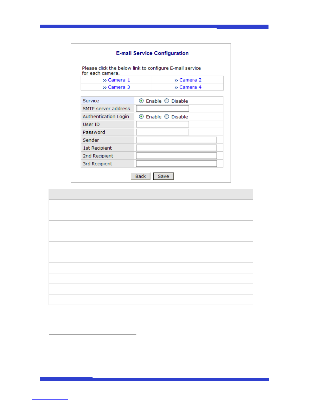
DNC(Dmax Network Camera) User’s Manual Part 3
DNC 50 Dongyang Unitech Co., Ltd
Item Description
Camera 1 – Camera 4 Select a channel to be configured for email notification
Service Select Enable in order to use this service
SMTP server address Enter SMTP server’s address for sending email.
Authentication Login Select Enable if SMTP server requires ID and p assword
User ID Enter User ID to log in to SMTP server
Password Enter Password to log in to SMTP server
Sender Enter email address of the sender
1st Recipient Enter the email address of the first recipient
2nd Recipient Enter the email address of the second recipient
3rd Recipient Enter the email address of the third recipient
Click Save button to apply the change. If you don’t want to change, click Back button.
E-mail Service Setup for Each Channel
For each channel, the following items can be configured for email service: Condition, Post-Alarm
Buffer Size, and Post-Alarm speed. The content of text message and display style of DI value can be
configured as well.
Page 99
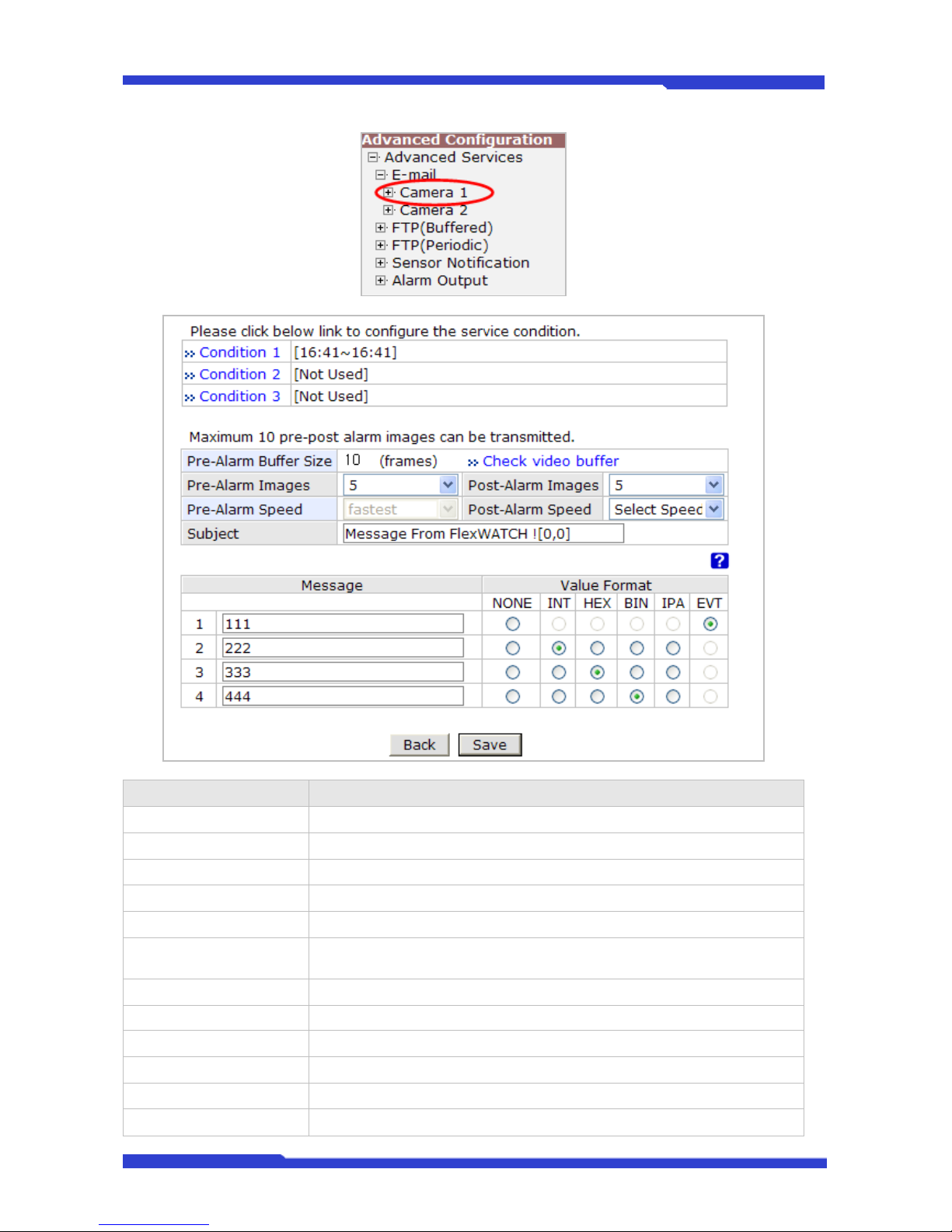
DNC(Dmax Network Camera) User’s Manual Part 3
DNC 51 Dongyang Unitech Co., Ltd
Item Description
Condition 1 ~ Condition 3 Select a condition for Email service to be activated.
Pre-Alarm Buffer Size The Buffer size assigned for Pre-Alarm.
Check Video buffer Click this link to go to Advanced Services for buffer setup.
Pre-Alarm Images The number of image frames to store before Alarm
Post-Alarm Images The number of image frames to store after Alarm
Pre-Alarm Speed
This field shows the speed of Pre-Alarm. Configuration can be done in
Advances Services page.
Post-Alarm Speed Select the speed of Post-Alarm. Fastest is the highest value.
Subject Subject of the E-mail message to send.
1 Content of the first line in the email message.
2 Content of the second line in the email message.
3 Content of the third line in the email message.
4 Content of the fourth line in the email message
Page 100
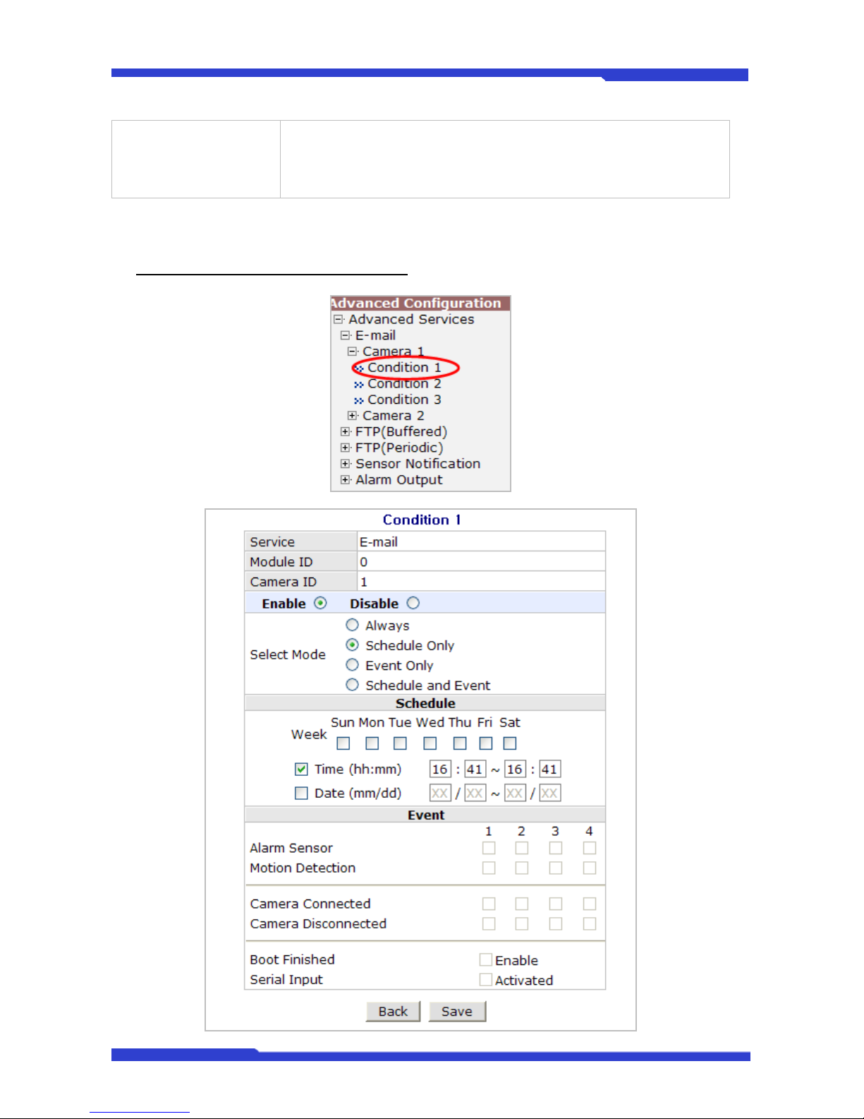
DNC(Dmax Network Camera) User’s Manual Part 3
DNC 52 Dongyang Unitech Co., Ltd
Value Format
Select the format for the Event or DI data to email.
NONE: Don’t Send, INT: Decimal
HEX: Hexadecimal, BIN: Binary
IPA: IP Address, EVT: Name of Event
After finishing setup, click Save button to apply. If you don’t want to change, click Back button.
Condition, Schedule & Event Configuration
 Loading...