

Page 1
Super Wide Dynamic Range
Color Camera
사용 설명서
MANUAL
용 서
DWC-540F
Page 2
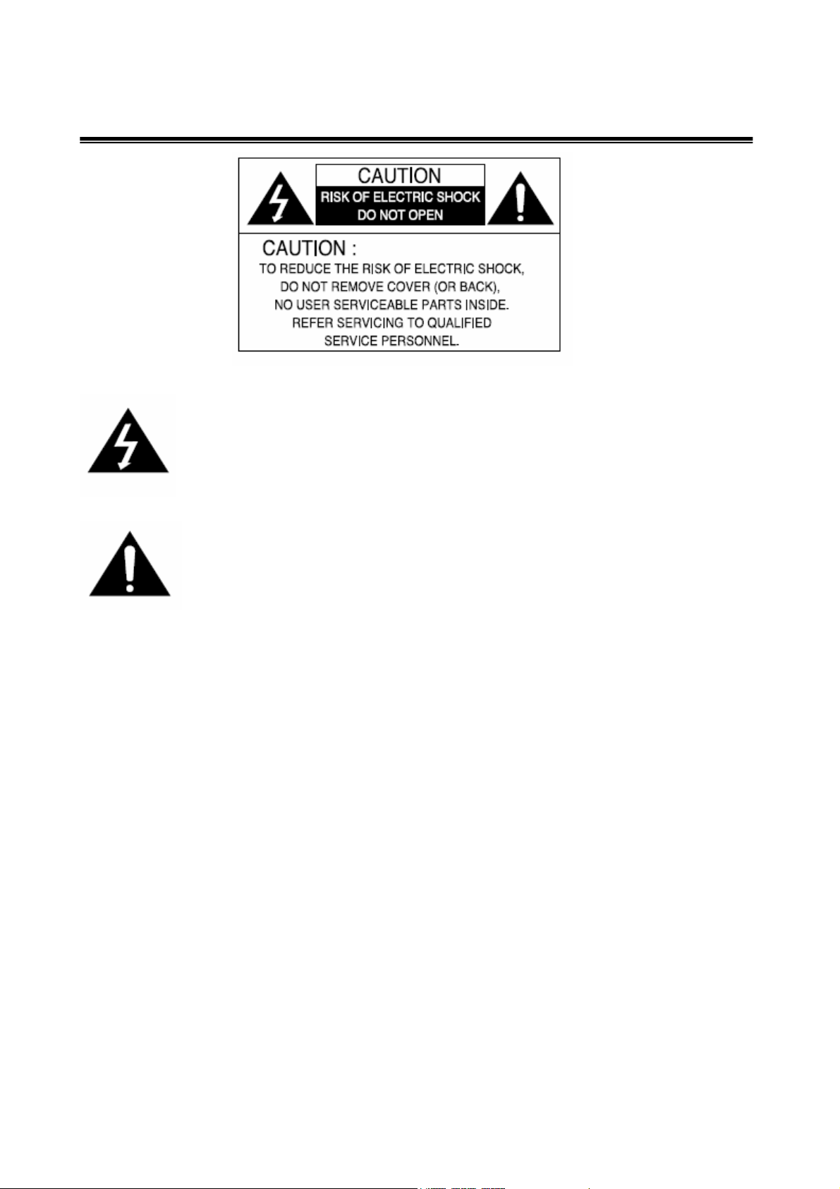
The lightning flash with an arrowhead symbol, within an equilateral
triangle is intended to alert the user to the presence of uninsulated
dangerous voltage within the product's enclosure that may be of
sufficient magnitude to constitute a risk of electric shock to persons.
The exclamation point within an equilateral triangle is intended to alert
the user to the presence of important operating and maintenance
(servicing) instructions in the literature accompanying the appliance.
INFORMATION - This equipment has been tested and found to comply with limits for a
Class A digital device, pursuant to part 15 of the FCC Rules.
These limits are designed to provide reasonable protection against harmful interference
when the equipment is operated in a commercial environment.
This equipment generates, uses, and can radiate radio frequency energy and, if not
installed and used in accordance with the instruction manual, may cause
harmful interference to radio communications.
Operation of this equipment in a residential area is likely to cause harmful interference in
which case the user will be required to correct the interference at his own expense.
WARNING - Changes or modifications not expressly approved by the manufacturer could
void the user’s authority to operate the equipment.
CAUTION : To prevent electric shock and risk of fire hazards:
Do NOT use power sources other than that specified.
Do NOT expose this appliance to rain or moisture.
This installation should be made by a qualified service person and should conform
to all local codes
2
Page 3

■ Warning
The camera needs periodic inspection.
Contact an authorized technician for inspection.
Stop using your camera when you find a malfunction.
If you use your camera around smoke or unusual heat for a long time,
fire may be caused.
Do not install the camera on a surface that can not support it.
Unless the surface is suitable, it could cause falling or other hazards.
Do not hold plug with wet hands.
It could cause an electric shock.
Do not disassemble the camera.
It may result in fire, electric shock or other hazards.
Do not use the camera close to a gas or oil leak.
It may result in fire or other hazards.
3
Page 4

■ Contents
1. Features
2. Components & Cable Connection
3. Names and functions of parts
4. Installation
5. Setup Menu flow
6. Setup page menu
7. Special page 1 menu
8. Special page 2 menu
--------------------------------
---------------------------------
---------------------------------
---------------------------------
--------------------------------
---------------------------------
---------------------------------
---------------------------------
9. Troubleshooting
10. Specifications
---------------------------------
---------------------------------
4
Page 5

1. Features
☺ High resolution color for crisp, clear video
▪ Progressive image capture
▪ 540 HTVL equivalent
☺ High sensitivity for low-light images
▪ Advanced noise reduction technology
☺ Wide Dynamic Range provides excellent quality in high-contrast
environments
▪ 120dB maximum dynamic range
☺ Optimum Exposure Mode presets
▪ Best pictures in a variety of applications
☺ EDNR (Electronic Digital Noise Reduction)
▪ The amount of low illuminance noise has been significantly reduced,
and the signal-to-noise ratio (S/N ratio) as well as horizontal resolution have
been improved, resulting in a clear and sharp image display even in the dark.
☺Controlled by OSD Menu
▪ The camera can be controlled by selecting text displayed on the monitor screen.
☺Additional Functions
▪ Automatic White Balance
▪ Backlight compensation
▪ Automatic Gain Control
▪ Activity / motion detection
▪ Digital Pan / Tilt / Zoom
▪ Day / Night
5
Page 6
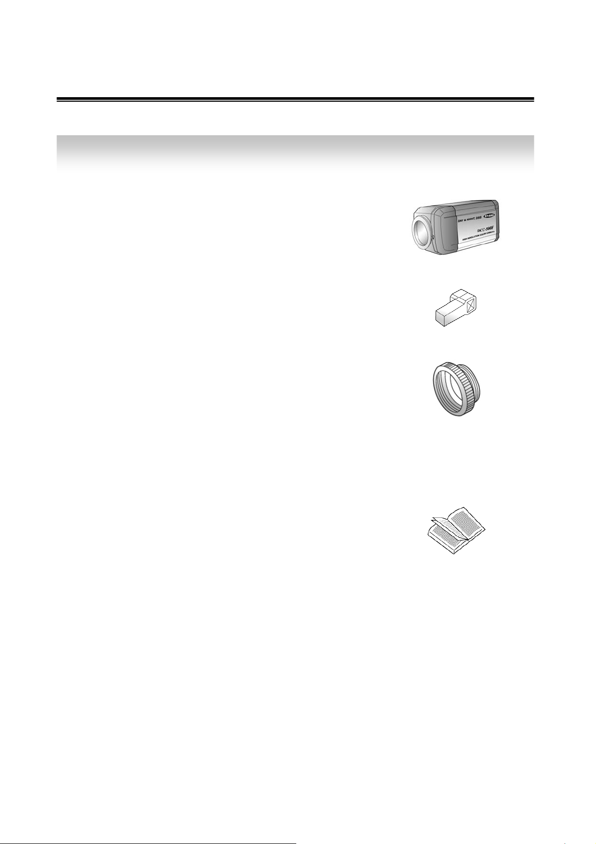
2. Components
1)
2)
3)
4)
COLOR CAMERA
AUTO IRIS LENS CONNECTION
PLUG
C-MOUNT ADAPTOR
L-WRENCH
-------------
-------------
-------------
-------------
5)
MANUAL
-------------
6
Page 7
3. Names and Functions of Parts
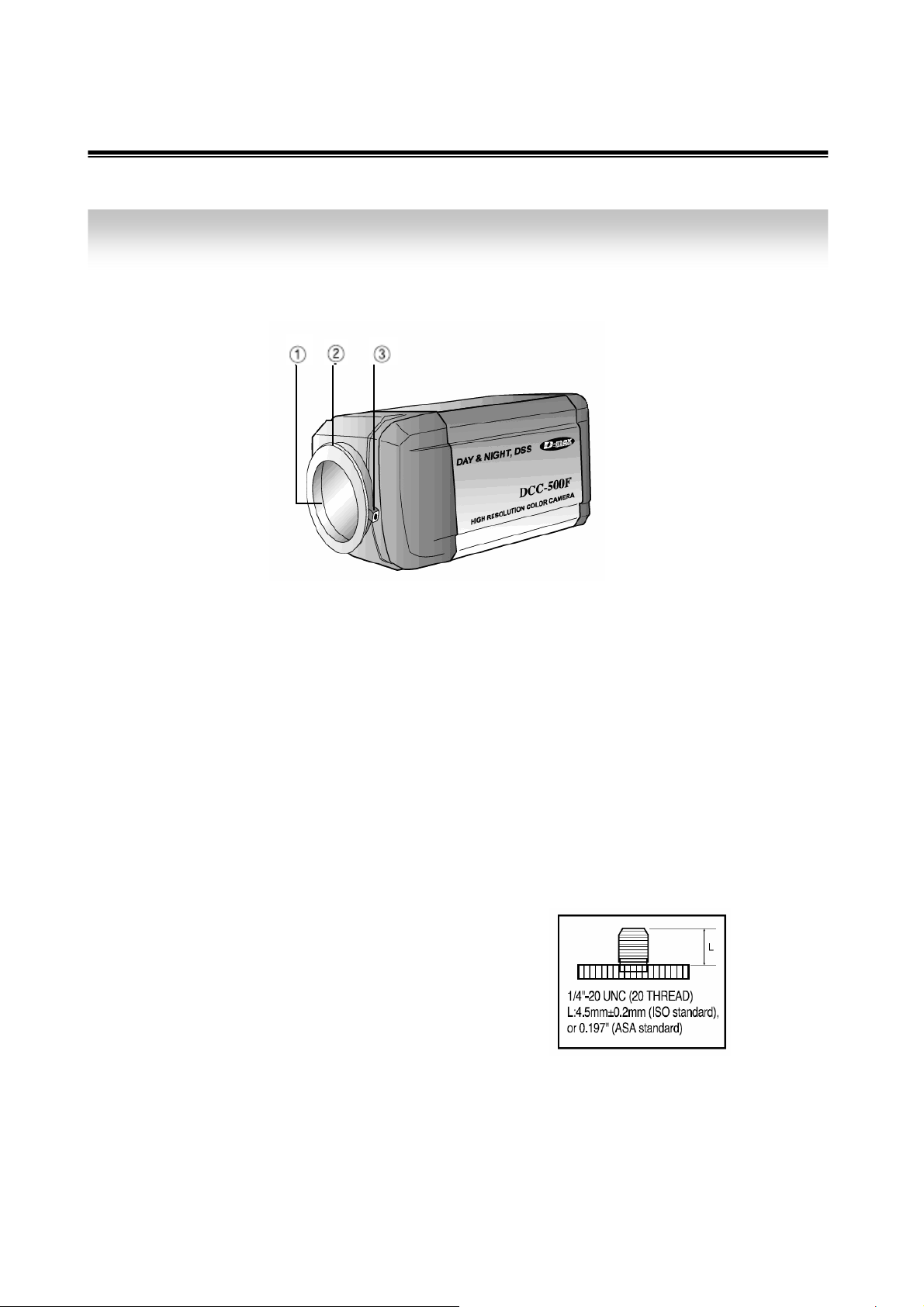
1) Front
① Lens protection cap
Please cover the lens when it is not in use.
② CS-Mount lens adaptor
Please attach the CS-Mount lens here.
③ Back Focus clamp screw
Please loosen the clamp screw with a screwdriver before adjusting the Back focal
length.
☞ Mounting bracket screw hole
Please use the screw hole when fixing the
camera onto the mounting bracket. Please use
the clamp screw as specified in the picture.
7
Page 8
☞ The mounting bracket can be separated and attached to the top of the camera.
In this instance please do not tighten the screw to a depth of more than 5mm,
otherwise serious damage can occur to the inner parts of the camera.
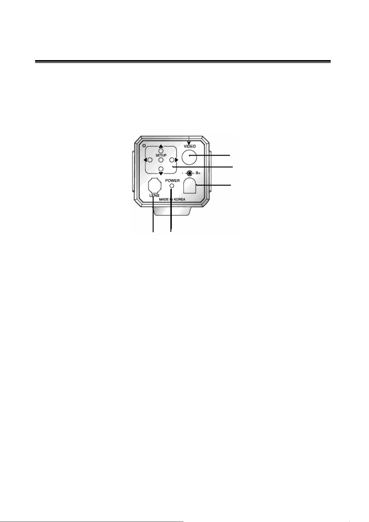
2) Back
②
④
⑤
① ③
① Auto iris lens connector
This is the connection terminal for the auto iris lens.
② Video output terminal
Sends video signals and connects to the video input terminal of the monitor.
③ Power lamp
Lights up when the correct power is supplied to the camera.
④ Setting button
SETUP button : Used for the menu display. This button can be used to confirm
settings after changing the value of the selected function or current conditions.
UP & DOWN buttons : Used for selecting items by moving the cursor up
Or down on the menu screen.
LEFT & RIGHT buttons : Used when changing item values, by moving
the cursor to the left or right on the menu screen.
⑤ Power input terminal
Connects to the power appropriate to each power requirement.
8
Page 9
4. Installation
1) Lens
Lenses are sold separately. Lenses such as auto iris lens, CS-Mount lens and C-Mount
lens can be used.
Note)
• Use of the DC auto iris lens is recommended to achieve the best results for operating this
product effectively.
• Please keep the lens clean.
• Any foreign objects and finger marks on the lens can cause inferior image quality in low
light level conditions.
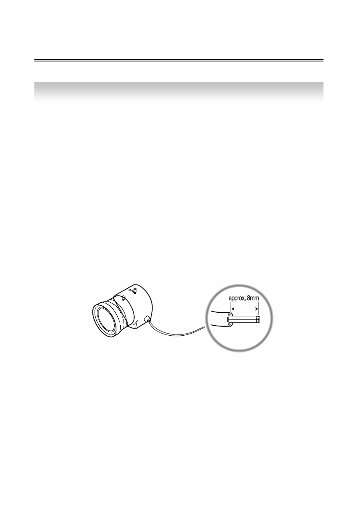
① When using an auto iris lens
- Please peel off about 8mm of the outer skin of the auto iris lens cable.
- Please peel off about 2mm of the outer skin of the insulated conductor inside the
lens cable
9
Page 10
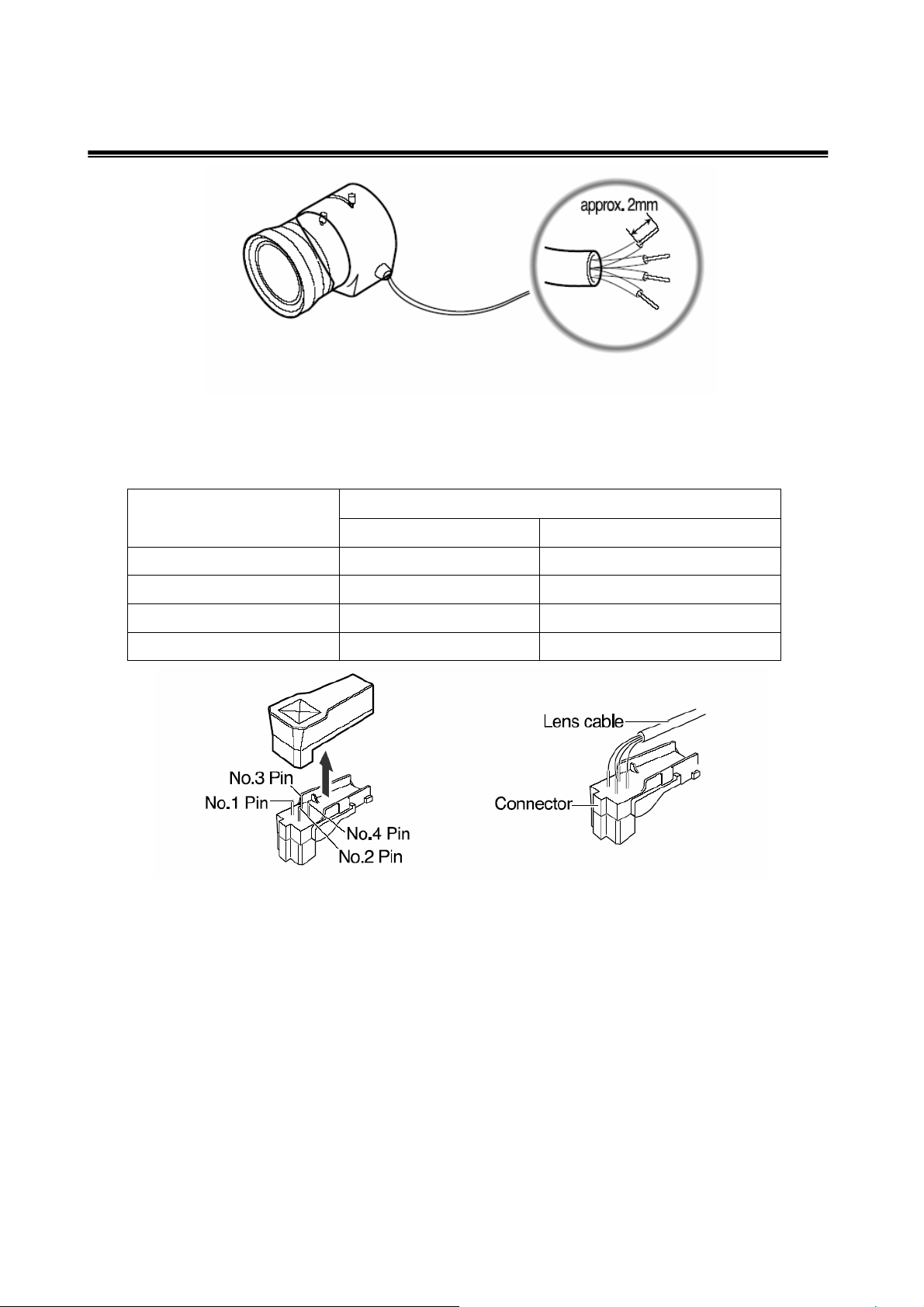
- Please remove the cover of the auto iris lens connection plug and solder the lens
cable to the connector pin in the plug.
Pin No.
LENS
DC VIDEO
No.1 Pin Damping- Red(power)
No.2 Pin Damping+ NC
No.3 Pin Drive+ White(video signal)
No.4 Pin Drive- Black(GND)
- Please replace the auto iris lens connection plug cover and take off the lens
protection cap, and then attach the auto iris lens to the camera by screwing it in
clockwise.
- Please insert the connection plug that is connected to the auto iris lens cable into
the auto lens connector, which is located on the back of the camera
10
Page 11
- Please set the lens selection switch, located on the back of the camera, to DC or
VIDEO depending on the type of auto iris lens which is being used.
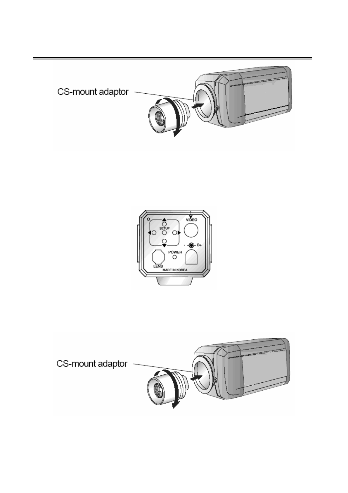
② When using a CS-Mount lens
Please take off the lens protection cap and attach the CS-Mount lens to the camera by
screwing it in clockwise.
11
Page 12
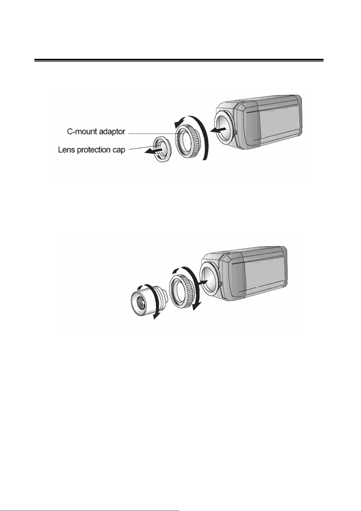
③ When using a C-Mount lens
Please take off the lens protection cap and attach the C-mount adaptor.
- Please attach the C-Mount lens to the
camera by screwing it in clockwise.
Note)
• Please use the specified lens connection parts as shown in the picture below.
The use of the wrong sized parts may cause damage to the inside of the camera or result
in poor fitting.
• Use of a lens which is too heavy affects the balance of the camera and may cause a
malfunction. Please use a lens that weighs less than 450g.
• Please select Av mode if possible when adjusting the automatic light control (ALC) of an
auto lens.
12
Page 13
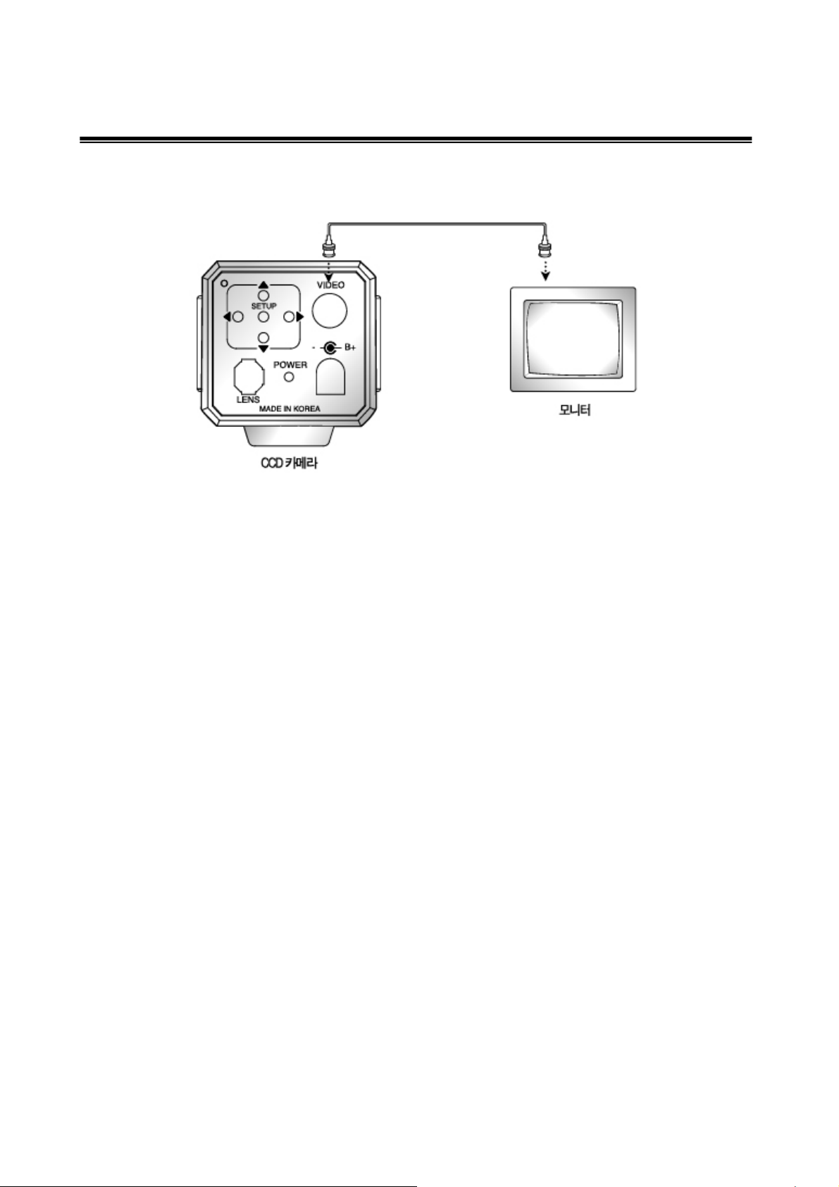
2) Connecting to a monitor
Please connect the video output terminal located on the back of the camera to the monitor.
• The connection method varies depending on the type of monitor and accessories.
Please refer to the user's manual for each instrument.
• Please turn off the power when connecting.
3) Connecting to power
DC Power Type (DC 12V, 300mA)
13
Page 14

5. Menu Flow
1) Setup Page Menu
LENS & VIDEO I/O SETUP LENS DC
VIDEO
MANUAL
VIDEO NTSC
PAL
RESOLUTION HIGH
NORMAL
WDR AUTO
HIGH
CUSTOM
LOW
WB CONTROL AUTO
ATWDes
AWC SAVE AWC & ALL CHNGS
MANUAL ADJ MODE KELVIN
AGC AUTO
OFF
LOW
HIGH
HIGHER
HI’EST
DNR AUTO
OFF
SENS & MOTION-UP DSS CONTROL 2FIELDS~32FIELDS
WHITE BALANCE SPEED
EXPOSURE SPEED
DYNAMIC RANGE SPEED
SPECIAL PAGE
EXIT
SETUP PAGE
14
Page 15

2) Special Page 1 Menu
CAMERA ID OFF
ON CAMERA ID
POSITION UP-DOWN
UP-CENTER
UP-RIGHT
DOWN-LEFT
DOWN-CENTER
DOWN-RIGHT
DAY&NIGHT OFF
AUTO
ON + Bur
ON
SYNC INT
EXT
MOTION OFF
ON
ZOOM PT OFF
ON
BACKLIGHT OFF
ON
AE PREFERENCE LIGHTS
SHADOW
SAVE & RETURN
PAGE 2
SPECIAL PAGE 1
3) Special Page 2 Menu
SPECIAL PAGE 2
MIRROR OFF
ON
FREEZE OFF
15 Frm
SET
FREEZE
SHARPNESS - 8 -------▪-------- 8
FLICKERNESS OFF
ON
FLUORESCENT LIGHT ON
OFF
FACTORY RESET
SYSTEM INFORMATION FW Rev
SAVE & RETURN
PAGE 1
15
Page 16

6. SETUP PAGE MENU
1. LENS & VIDEO I/O SET
1) Lens
Choose the lens type DC, Video and manual lens by using the selector button.
2) Video I/O
Choose video system between PAL and NTSC by moving the selector.
▶LENS & VIDEO I/O SETUP LENS DC
VIDEO
MANUAL
VIDEO NTSC
PAL
RESOLUTION HIGH
WDR AUTO
WB CONTROL AUTO
AGC AUTO
DNR AUTO
SENS & MOTION-UP DSS CONTROL
EXIT
SETUP PAGE
2. RESOLUTION
Choose resolution between high and normal with the selector (right/left).
The high resolution supports Progressive Rate video up to 540 TV Line and the normal
resolution supports 480 TV Line.
SETUP PAGE
LENS & VIDEO I/O SETUP
▶RESOLUTION HIGH
NORMAL
WDR AUTO
WB CONTROL AUTO
AGC AUTO
DNR AUTO
SENS & MOTION-UP DSS CONTROL
EXIT
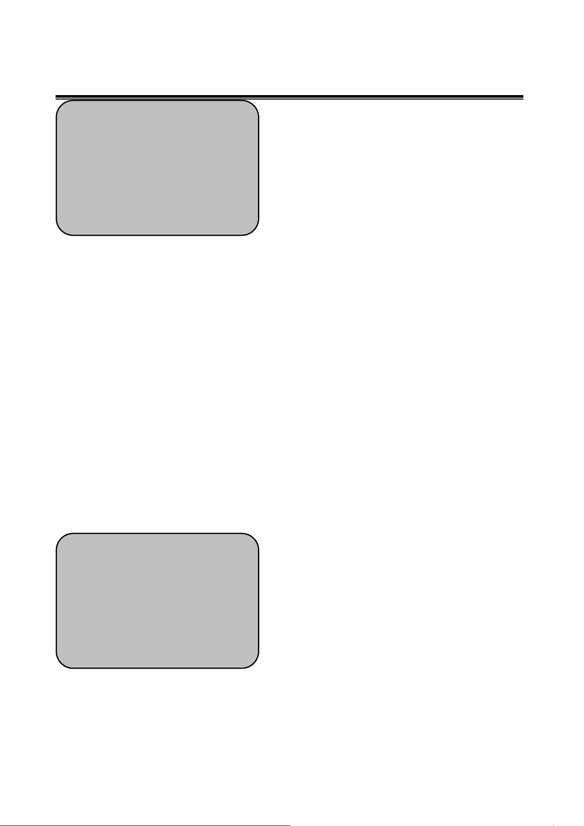
3. WDR
Wide Dynamic Range is essential for capturing the images at all light levels.
The main function of the WDR is to accumulate the scope of contrast between the
brightest and darkest points in the picture. With the AUTO option, the distribution of
brightness values is automatically adapted to the recording scenario.
User can select the desired level HIGH, CUSTOM & LOW , in addition to automatic
adaptation (Auto), by moving the selector button.
16
Page 17
SETUP PAGE
LENS & VIDEO I/O SETUP
RESOLUTION HIGH
▶WDR AUTO
HIGH
CUSTOM
LOW
WB CONTROL AUTO
AGC AUTO
DNR AUTO
SENS & MOTION-UP DSS CONTROL
4. WB CONTROL (White Balance Modes)
White Balance is a function which compensates different colors of light being emitted from
different light Sources.
Users can select the above levels as they desire or according to the Environment.
1) Auto Tracking White Balance (ATW)
The Auto Tracking White Balance (ATW) mode continuously monitors color temperature..
With WB Control set to ATW, Color temperature & White balance can be automatically
adjusted accordingly.
2) AWC (Auto White Balance)
When set to AWC, Color temperature of the Light is automatically adjusted.
3) Manual ( Manual White Balance )
Manual White Balance (MWB) Mode is used when other White Balance Options are failed.
4) ATWDesat ( ATW Desaturating )
When WB is set to ATWDesat, the Extended Color temperature is desaturated i.e when
there is a excess of Light temperature , ATWDesat Function is used as well as it reduces
the Noise. The limits of the color temperature setting remain 2000K and 11,000K.
SETUP PAGE
LENS & VIDEO I/O SETUP
RESOLUTION HIGH
WDR AUTO
▶WB CONTROL AUTO
ATWDes
AWC
MANUAL
AGC AUTO
DNR AUTO
SENS & MOTION-UP DSS CONTROL
5. AGC
Automatic Gain Control ( AGC) is a feature which adjust automatically according to the
incoming Signal.
By positioning the arrow to 'AGC' on the SETUP menu with the help of UP and DOWN
17
Page 18

buttons ,you can select the Mode you wish to go
1) AGC AUTO: The Sensitivity increases automatically When the light is Low.
2) AGC OFF : A Low Noise Picture is obtained under a low light.
As the level of gain increases, the screen gets brighter and the level of noise also
increases.
SETUP PAGE
LENS & VIDEO I/O SETUP
RESOLUTION HIGH
WDR AUTO
WB CONTROL AUTO
▶AGC AUTO
OFF
LOW
HIGH
HLGHER
HI’EST
6. DNR AUTO/OFF
DNR is Digital Noise Reduction System with a maximum gain of 24 DB.
By Setting it to AUTO Mode, Noise Will be Little & Vice versa in OFF mode.
SETUP PAGE
LENS & VIDEO I/O SETUP
RESOLUTION HIGH
WDR AUTO
WB CONTROL AUTO
AGC AUTO
▶DNR AUTO
OFF
SENS & MOTION-UP DSS CONTROL
EXIT
7. SENS & MOTION-UP
You can control DSS levels and speed levels of the camera to optimize the camera
condition as given below.
SETUP PAGE
LENS & VIDEO I/O SETUP
RESOLUTION HIGH
WDR AUTO
WB CONTROL AUTO
AGC AUTO
DNR AUTO
▶SENS & MOTION-UP DSS CONTROL
WHITE BLANCE SPEED
EXPOSURE SPEED
DYNAMIC RANGE SPEED
EXIT
18
Page 19

1) DSS CONTROL ( DIGITAL SLOW SHUTTER )
The Levels of Fields are ranged from 2X ~32X.
User can set slow shutter limit from 2x ~ 32x and select COLOR or B/W image when slow
shutter is operation by setting SS PROTERTY.
When DSS is set OFF, it operates with AGC in low light condition to keep the color image.
When DSS is set “ON” ,the camera will merge into the slow shutter mode in low light
condition.
The default SLOW SHUTTER setting is OFF.
2) WHITE BALANCE SPEED
① ATW Slew
ATW slew Controls the rate of change when transitioning from one color thmperature to
another,
An example of this would be panning the camera from an indoor fluorescent scene of
4000K out a window to a daylight scene of 6500K.
The slew property tells the camera how fast to make the adjustment from 4000K to 6500K.
The property itself is a value from 1 to 100, with I being the fastest slew and 100 being the
slowest.
② HYST
White balance auto hysteresis sets a threshold around the current color temperature
reading.
The measured color temperature must exceed this threshold before the current white
balance setting will change.
The purpose of hysteresis is to ensure that the camera does not dither back and forth
between two different modes of operation, when the meter reading are near a boundary
between the two mode.
However making the hysteresis threshold too high will make the camera appear
unresponsive.
3) EXPOSURE & Dynamic range speed
① Filter
The first step in processing camera response and transition rates is to apply a low-pass
filter to incoming exposure readings. This filter can be set to prevent the camera from
responding to very fast transient changes in meter readings.
The typical use of the filter is to keep the camera output stable when monitoring a high
activity scene.
19
Page 20

② HYST
The filter block is followed by the hysteresis block. It requires the filtered exposure
readings to exceed a programmable threshold before the camera will respond.
This can prevent the camera from dithering back and forth between two different modes of
operation when the meter readings are near a boundary between the two modes.
However setting the hysteresis parameters too high can make the camera appear
unresponsive..
The filter and hysteresis blocks effectively control what scene changes the camera will
respond to. They can be set to make the camera effectively ignore changes that are too
fast or too small. If a change in meter reading is substantial enough to pass through these
two blocks, the camera will respond. Then it’s a question of how quickly the camera
will respond—which is the purpose of the next block.
③ Trans
The role of the transition block is to control the rate of the transition from old to new
camera settings.
They control how big a transition can be made from the current setting to the target setting
at each step.
Set to their maximum values, the camera can make the transition from old to new setting
in one step.
Though the transition is as fast as possible, it can appear very rough.
Smaller values for the transition properties make the transitions smoother but slower.
20
Page 21

7. SPECIAL PAGE 1 MENU
1. CAMERA ID
User can enter a unique name for the respective camera.
The maximum length of the ID is eight characters.
1) ID Position.
Select the desired position with the selector (right/left).
2) ID Display.
We can choose the ON and OFF with the selector (right/left). If you select ON, the entered
camera ID is displayed at the selected position in the video picture (normal operation).
SPECIAL PAGE 1
▶CAMERA ID OFF
ON
DAY&NIGHT OFF
SYNC INT
MOTION OFF
ZOOM PT OFF
BACKLIGHT OFF
AE PREFERENCE LIGHTS
SAVE & RETURN
2. DAY&NIGHT
Day/Night mode helps to increase the camera sensitivity in very dark situations
1) When Day&Night is OFF, Day& Night is inactivated.
2) When Day& Night is ON , it comes into affect.
3) When Day & Night is AUTO, it produces monochrome light automatically .
4) When Day& Night is ON + BUR, it produces monochrome light i.e Black &white With
color Burst.
SPECIAL PAGE 1
CAMERA ID OFF
▶DAY&NIGHT OFF
AUTO
ON+Bur
SYNC INT
MOTION OFF
ZOOM PT OFF
BACKLIGHT OFF
AE PREFERENCE LIGHTS
3. SYNC
“ Sync “ mode is fixed to INT in DC12V input power
21
Page 22
4. MOTION
This setting has a maximum gain of 24dB. This setting does not use DNR at high gain.
The images are sharper than DNR but the visible gain in the image is greater.
SPECIAL PAGE 1
CAMERA ID OFF
DAY&NIGHT OFF
SYNC INT
▶MOTION OFF
ON
ZOOM PT OFF
BACKLIGHT OFF
AE PREFERENCE LIGHTS
SAVE & RETURN
5. ZOOM PT ON/OFF
Digital P/T/Z are used to create a zoom lens effect. Factor Zoom Factor (1x to 4x)
Pan (±100%, center of image can be moved to left and right edges of screen)
Tilt (±100%, center of image can be moved to top and bottom edges of screen)
1) By Selecting ON, Zoom PT is enabled.
2) By Selecting OFF, Zoom PT is disabled.
SPECIAL PAGE 1
CAMERA ID OFF
DAY&NIGHT OFF
SYNC INT
MOTION OFF
▶ZOOM PT OFF
ON
BACKLIGHT OFF
AE PREFERENCE LIGHTS
SAVE & RETURN
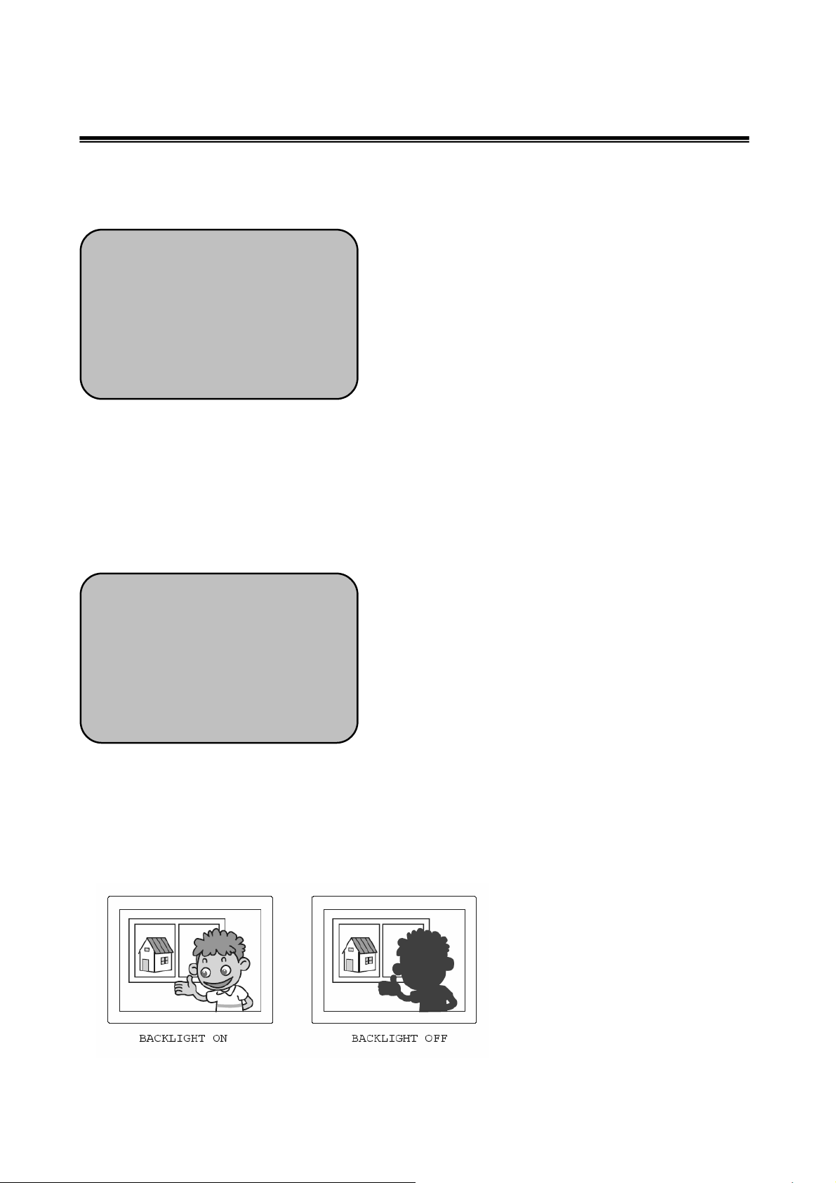
6. BACKLIGHT ON/OFF
Backlight is feature of a Camera which compensates when there is a large amount of
Background light.
1) When Backlight is ON, Back Light gets activated.
2) When Backlight is OFF, it is inactivated.
22
Page 23

SPECIAL PAGE 1
CAMERA ID OFF
DAY&NIGHT OFF
SYNC INT
MOTION OFF
ZOOM PT OFF
▶BACKLIGHT OFF
ON
AE PREFERENCE LIGHTS
SAVE & RETURN
7. AE PREFERENCE
The camera user has a choice to optimize the scene when high dynamic range lighting is
detected by setting the Automatic Exposure Preference.
1) SHADOW
When AE Preference is set to shadow, the camera will adjust the exposure so that dark
parts of the image are most visible; bright parts of the image may saturate.
2) LIGHTS
When AE Preference is set to highlights, the camera will adjust the exposure so that bright
parts of the image are most visible; dark parts of the image may go to black.
SPECIAL PAGE 1
CAMERA ID OFF
DAY&NIGHT OFF
SYNC INT
MOTION OFF
ZOOM PT OFF
BACKLIGHT OFF
▶AE PREFERENCE LIGHTS
SHADOW
SAVE & RETURN
23
Page 24
8. SPECIAL PAGE 2 MENU
1. MIRROR
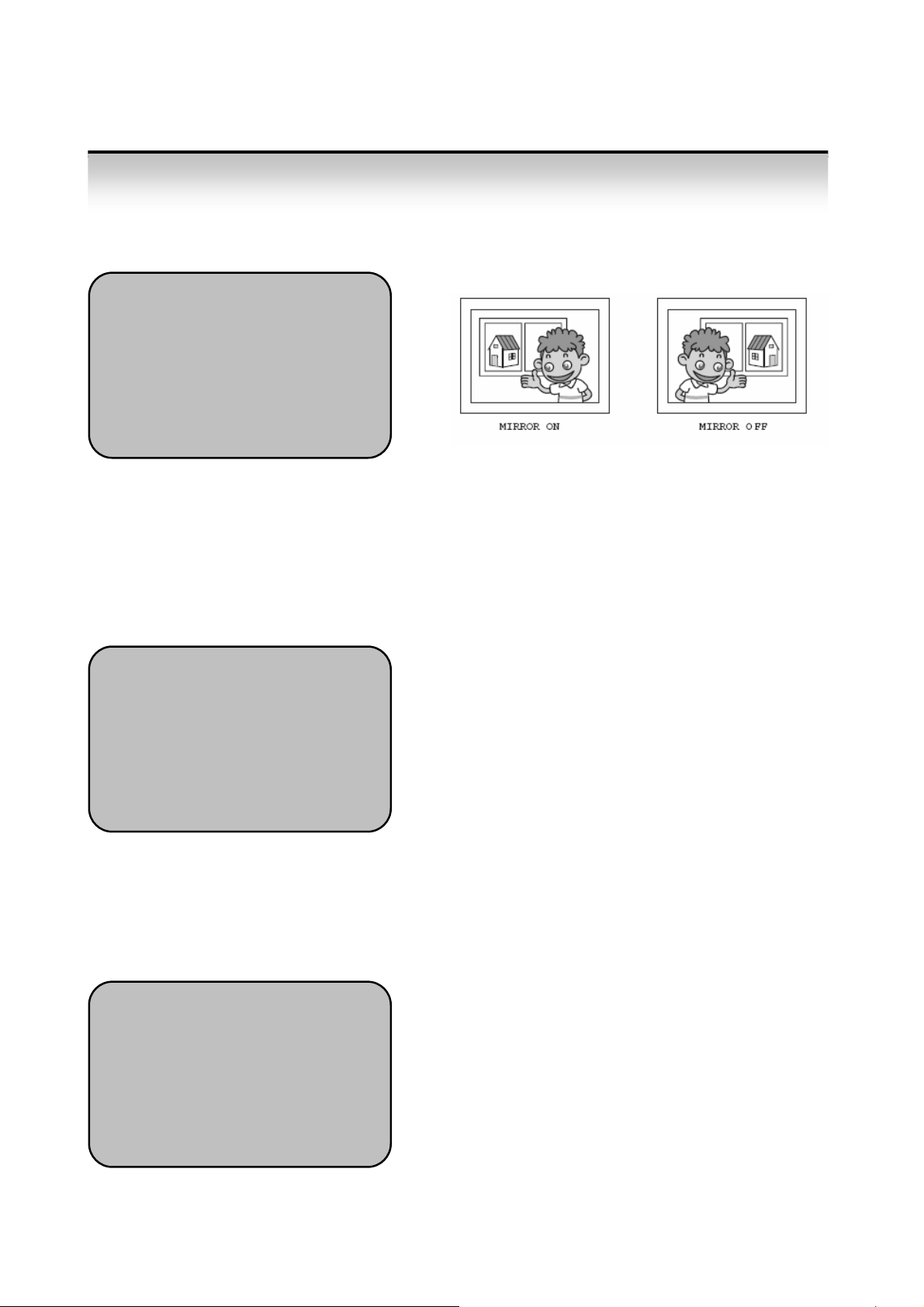
Select “OFF” to show the image as normal. Select “ON” to reflect image horizontally.
SPECIAL PAGE 2
▶MIRROR OFF
ON
FREEZE OFF
SHARPNESS - 8 --▪-- 8
FLICKERNESS OFF
FLUORESCENT LIGHT ON
FACTORY RESET
SYSTEM INFORMATION FW Rev
2. FREEZE
When frame repeat count is set to 0, the same image continues to repeat until the property
value is changed. This has the effect of a “freeze frame.”
Note: If frame repeat count is set to 0 (Freeze), the user should NOT be allowed to do a
save user settings, as this will cause an inconsistent state with no loaded image at
boot/reset.
SPECIAL PAGE 2
MIRROR OFF
ON
▶FREEZE OFF
15 Frm
SET
SHARPNESS - 8 --▪-- 8
FLICKERNESS OFF
FLUORESCENT LIGHT ON
3. SHARPNESS
Adjust the SHARPNESS level of full screen by setting the “GAIN” level from -8 ~8.
Select “ HORIZONTAL” for adjusting H. SHARPNESS only.
The larger the SHARPNESS parameter, the sharper the images.
SPECIAL PAGE 2
MIRROR OFF
ON
FREEZE OFF
▶SHARPNESS - 8 --▪-- 8
FLICKERNESS OFF
FLUORESCENT LIGHT ON
FACTORY RESET
SYSTEM INFORMATION FW Rev
24
Page 25

4. FLICKERNESS ON/OFF
The slow shutter mode can be used manually to reduce flicker caused from fluorescent
lights when linelock
synchronization is not available.
When Flickerness set to OFF, trembleming is reduced ( Default).
When Flickerness set to ON,
SPECIAL PAGE 2
MIRROR OFF
ON
FREEZE OFF
SHARPNESS - 8 --▪-- 8
▶FLICKERNESS OFF
ON
FLUORESCENT LIGHT ON
FACTORY RESET
5. FLUORESCENT LIGHT
1) On
Reduces color rolling that may occur under some types of fluorescent lighting.
For best results, line lock synchronisation is recommended. If line lock synchronisation is
not possible, an auto-iris lens should be used.
2) Off (default)
The default setting maximises dynamic range
SPECIAL PAGE 2
MIRROR OFF
ON
FREEZE OFF
SHARPNESS - 8 --▪-- 8
FLICKERNESS OFF
ON
▶FLUORESCENT LIGHT ON
FACTORY RESET
6. FACTORY RESET
Restores the camera to the factory defaults.
6. SYSTEM INFORMATION
Displays the camera firmware version - This may be required during any call to Dongyang
Unitech Technical Support.
25
Page 26
9. Troubleshooting
If there are problems in operation, please refer to the items below. If the problem persists,
please contact the agent you purchased this product from.
Problems Troubleshooting
Nothing appears on the screen.
The video image is not clear.
The screen is dark.
There is a problem with the
camera operation.
The MOTION DETECTION function
is not working.
• Please check the power connection.
• Please check the video signal line connection.
• Please check if the lens is clean.
Please clean the lens with a clean cloth or brush.
• Please adjust the contrast feature of the monitor.
• Please readjust the back focus of the camera.
• Please adjust the contrast feature of the monitor.
• If you have an intermediate device, set the 75 / Hi-z
properly, and check the terminals.
• Please check if an auto iris lens is being used and adjust
the brightness level.
• Please check if an appropriate power source to the
camera complies with the manufacturer's
standard requirement, or if the voltage keeps changing.
• Please check if 'MOTION DETECTION' mode is turned
on.
Colors are not quite right.
The screen is flickering.
COLOR mode is not working.
• Please check the setting of the MD AREA.
• Please check the 'WHITE BAL' setting
• Please check if the camera is facing directly into sunlight
or fluorescent light.
• Please check if an auto iris lens is being used.
• Please check the connection of the lens connector cable.
• Please check if the AGC menu is set to the OFF
position.
26
Page 27

10. SPECIFICATIONS
GENERAL
Imaging Device 1/3-inch DPS ORCA CHIPSET
Dynamic Range 95 dB typical/120 dB maximum
Picture Elements Sensor resolution: 742 (H) x 552 (V)
Scanning System 525 (NTSC)/625 (PAL) lines, 2:1 interlace
Horizontal Resolution More than 540 TV lines (Normal 480TV Line)
Iris Control Automatic/manual
Auto Iris Lens Type DC-drive
Minimum Illumination 0.4 lux, F1.2, 40 IRE, AGC on
Signal-to-Noise Ratio >50 dB
Automatic Gain Control On-screen menu, adjustable to 21 dB
Backlight Compensation On-screen menu
Signal Processing SIMD digital signal processing (DSP)
Video Output 1.0 to 1.2 Vp-p, 75 ohms
Auto White Balance Range 2,000° to 11,000°K
ELECTRICAL
Power Requirements 12 VDC ±10% or 24 VAC ±10%, 50/60 Hz;
Power Consumption 4.5 watts maximum
Video Connector BNC
Analog composite video
Auto Iris Connector 4-pin connector (miniature square)
Lens Mount C/CS mount
Camera Mount 1/4-inch UNC-20 screw, top or bottom of camera housing
ENVIRONMENTAL
Operating Temperature -10° to 50°C
Storage Temperature -40° to 60°C
Humidity 20% to 80%,
PHYSICAL
Dimensions 104( D) x 61 (W) x 55( H) mm
Weight (without lens) about 800g
(Design and product specifications subject to change without notice.)
27
Page 28

28
Page 29

29
Page 30

30
Page 31

31
 Loading...