

Page 1
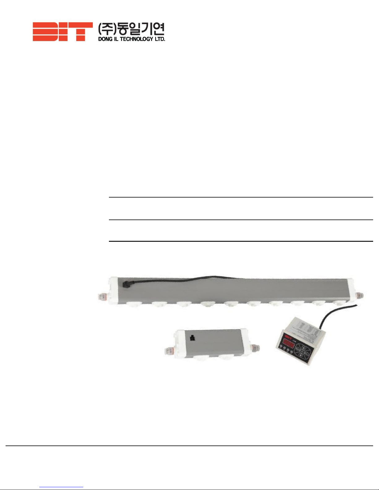
Instruction Manual
ION BAR ASM-P Series
Controller ASM-C
Read this instruction manual before using the product in order to achieve maximum performance.
Keep this instruction manual within your reach after reading so that it can be used at any time.
ASM controller can be used for both ASM and ASR series.
28, Namyang-ro 930beon-gil, Hwaseong-si, Gyeonggi-do, Korea
Tel 031-299-5453 Fax 031-357-2610
Page 2

CONTENTS
1. Product Introduction 03Page
1.1 Features 1.2 Specification
1.3 Dimensions 1.4. Performance
1.5 Package contents 1.6 Part names
1.7 Cautions and warranty
2. Installation & Connection 10Page
2.1 Installation location 2.2 Purging and moving into CR
2.3 Wiring diagram 2.4 Installing and connecting main body
2.5 Connecting multi bars 2.6 Check list after installation
3. Settings 18Page
3.1 Setting values using an ASM controller
4. Maintenance 20Page
4.1 Necessity of the maintenance 4.2 How to clean and replace an emitter
APPENDIX 22Page
1. Trouble shooting
2
DONG IL TECHNOLOGY LTD
Before installation, be sure to read carefully at least
1.7 Cautions & Warranty (P.9)
2. Installation & Connection parts (P.10 ~ P.17)
Page 3
ASM-P Series is,
Bar and controller can be installed separately.
(Up to 4 bars can be connected to 1 controller)
More suitable for medium-short distance static elimination.
For long distance static elimination, we recommend our ASM-A Series.
Safe from fire by using own piezo-ceramic for HVPS(High Voltage Power Supply).
Able to keep stable Ion Balance due to its high-frequency method.
1.1 Features
3
Welcome to become a customer of DIT!
ASM-P series is a slim bar ionizer designed to be more convenient to monitor and
control the product by separating its controller, while succeeding the outstanding
performance of ASG-P series.
1. Product Introduction
1.1 SG-A Series 제품 특징
1. 2 Specifications
※ Specification can be changed without notice for performance improvement.
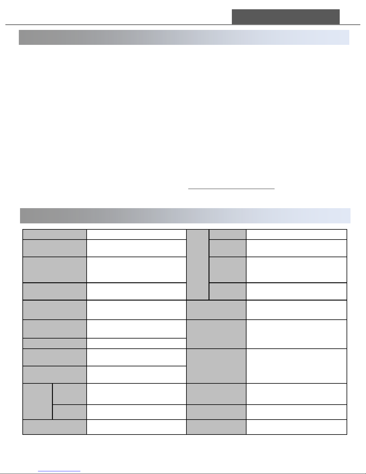
Series name ASM – P
Air
Type CDA, N2
Length
Min 150 ~ Max 3000 mm
(increasing by 50mm)
Pressure 0 ~ 0.5Mpa(Usually under 0.3Mpa)
Ion generating method Corona discharge Flow
2.0L/min(±10%) per 1 emitter
(under 0.1Mpa)
Voltage application
method
High Frequency AC
Air tube
diameter
6 pi (outside)
Input Voltage DC24V±10% Material
Main body: ABS /
Emitter pin: Tungsten
Input Current
MAX. 2.4A (Controller )
MAX. 600mA (1Bar=3000mm)
Display
(ASM-C)
Alarm LED(Green/Red) 4ea,
Output Voltage
±
4.7 kVp-p 3-Digit(Error and Status display)
Output Frequency 29 KHz
Controllable factors
(ASM-C)
Ion on/off, Address,
Communication speed
Password, Resetting,
Tip cleaning period setting
Ion Balance Under average ±30V
Weight(g)
BAR
Min : 175g(ASM-P150),
Max :3Kg(ASM-P300)
Power consumption
MAX.17W (1BAR )
MAX.57W (4BAR)
Controller Max : 100g Ambient temperature 0℃~ +50℃(32~113℉)
Ozone generation Under 0.05ppm Relative humidity 35~85%RH(No dewing)
DONG IL TECHNOLOGY LTD
Page 4
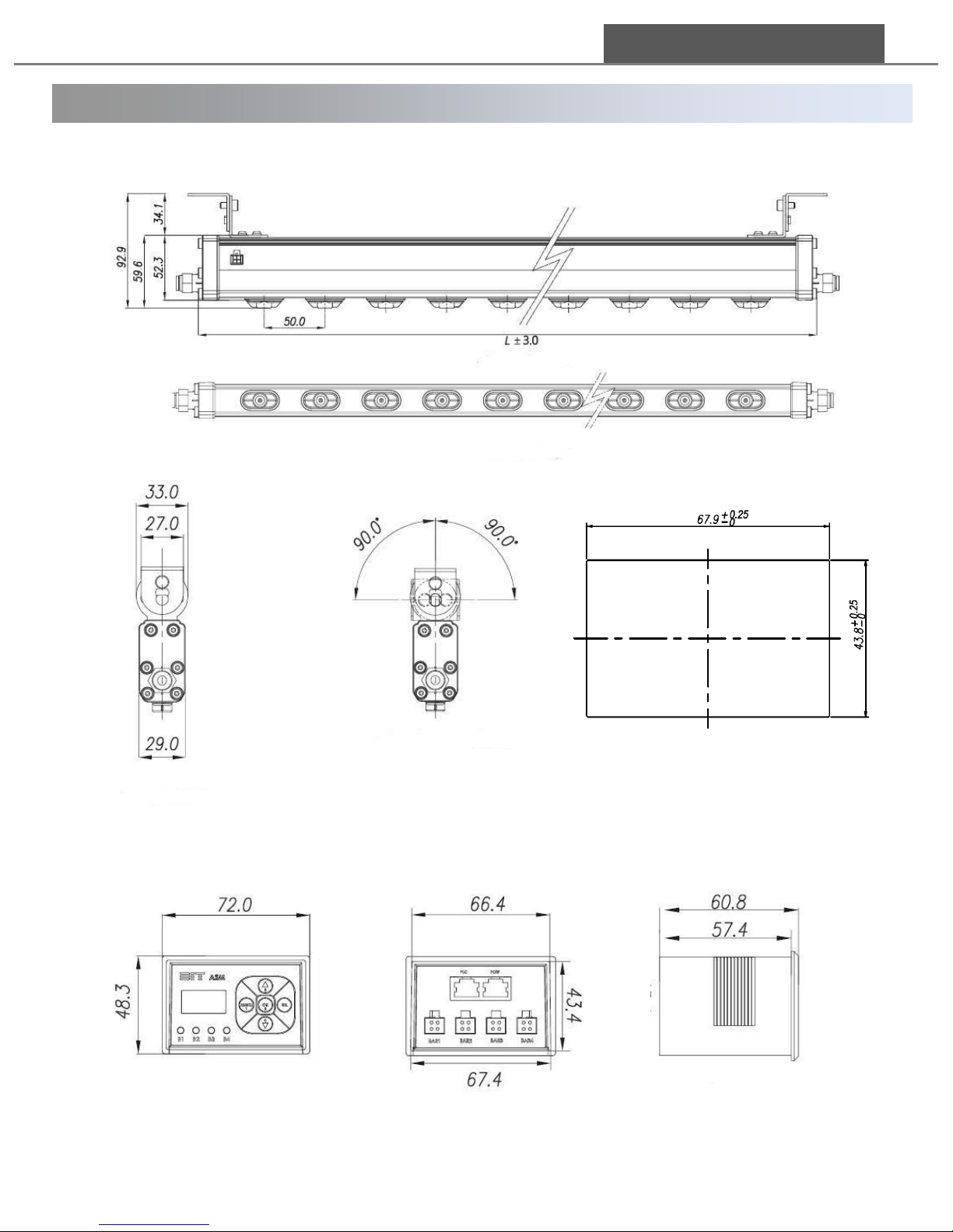
1. 3 Dimensions
4
<Bar>
DONG IL TECHNOLOGY LTD
<Front view>
<Bottom view>
<Side view> <Bracket rotation>
<Controller>
<Controller Front view>
<Controller Rear view> <Controller Side view>
<Panel cut-out>
Page 5
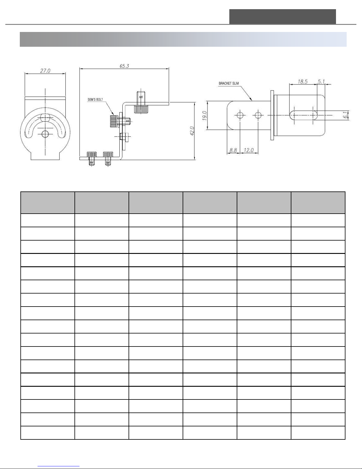
1. 3 Dimensions
Model
Number of
emitters(EA)
Length(mm)
Model
Number of
emitters(EA)
Length(mm)
ASM-P015
2
146
ASM-P140
27
1396
ASM-P020
3
196
ASM-P150
29
1496
ASM-P025
4
246
ASM-P160
31
1596
ASM-P030
5
296
ASM-P170
33
1696
ASM-P035
6
346
ASM-P180
35
1796
ASM-P040
7
396
ASM-P190
37
1896
ASM-P045
8
446
ASM-P200
39
1996
ASM-P050
9
496
ASM-P210
41
2096
ASM-P055
10
546
ASM-P220
43
2196
ASM-P060
11
596
ASM-P230
45
2296
ASM-P070
13
696
ASM-P240
47
2396
ASM-P080
15
796
ASM-P250
49
2496
ASM-P090
17
896
ASM-P260
51
2596
ASM-P100
19
996
ASM-P270
53
2696
ASM-P110
21
1096
ASM-P280
55
2796
ASM-P120
23
1196
ASM-P290
57
2896
ASM-P130
25
1296
ASM-P300
59
2996
5
DONG IL TECHNOLOGY LTD
<Bracket>
<Number of emitters & Length by Model>
Page 6
300
600
900
1,200
-300 -200 -100 0 100 200 300
Height Direction [mm]
Deepth Direction [mm]
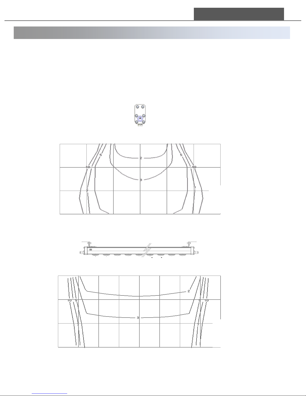
Relation Between Depth Direction and Decay Time
300
600
900
1,200
-100 0 100 200 300 400 500 600 700
Height Direction [mm]
Width Direction [mm]
Relation Between Width Direction and Decay Time
1.4 Performance
Measurement Condition
Air purge : 0.3 Mpa
Charged plate dimensions : 150 x 150mm
Capacity : 20pF
Decay time condition : 1kV -> 0.1 kV
DONG IL TECHNOLOGY LTD
Measurement Condition
Air purge : 0.3 Mpa
Charged plate dimensions : 150 x 150mm
Capacity : 20pF
Decay time condition : 1kV -> 0.1 kV
Relation between discharge time and distance(Distance: mm, discharge Time: sec) :
shows discharge time according to the distance measured in product’s side and
front perspective. (Product: ASM-P060W/Place: DIT Test-Room)
※ Discharge time: the time necessary for static elimination
Page 7
Trade name
Order code
Image
Notes
Ion Emitter Kit for Replacement
ASU-P01
10pcs / 1 set
RJ45 Cable( 8pin)
[Connecting Controller and Power/PLC]
ASU-R018A
1m
ASU-R028A
2m
ASU-R038A
3m
ASU-R048A
4m
ASU-R058A
5m
ASU-R108A
10m
4PIN CONNECTOR CABLE
[Connecting Bar and Controller]
ASU-C01
1m
ASU-C02
2m
ASU-C03
3m
ASU-C04
4m
ASU-C05
5m
ASU-C10
10m
ASU-C15
15m
Brackets
ASU-BA
Ceiling mount
ASU-BB
Floor mount
7
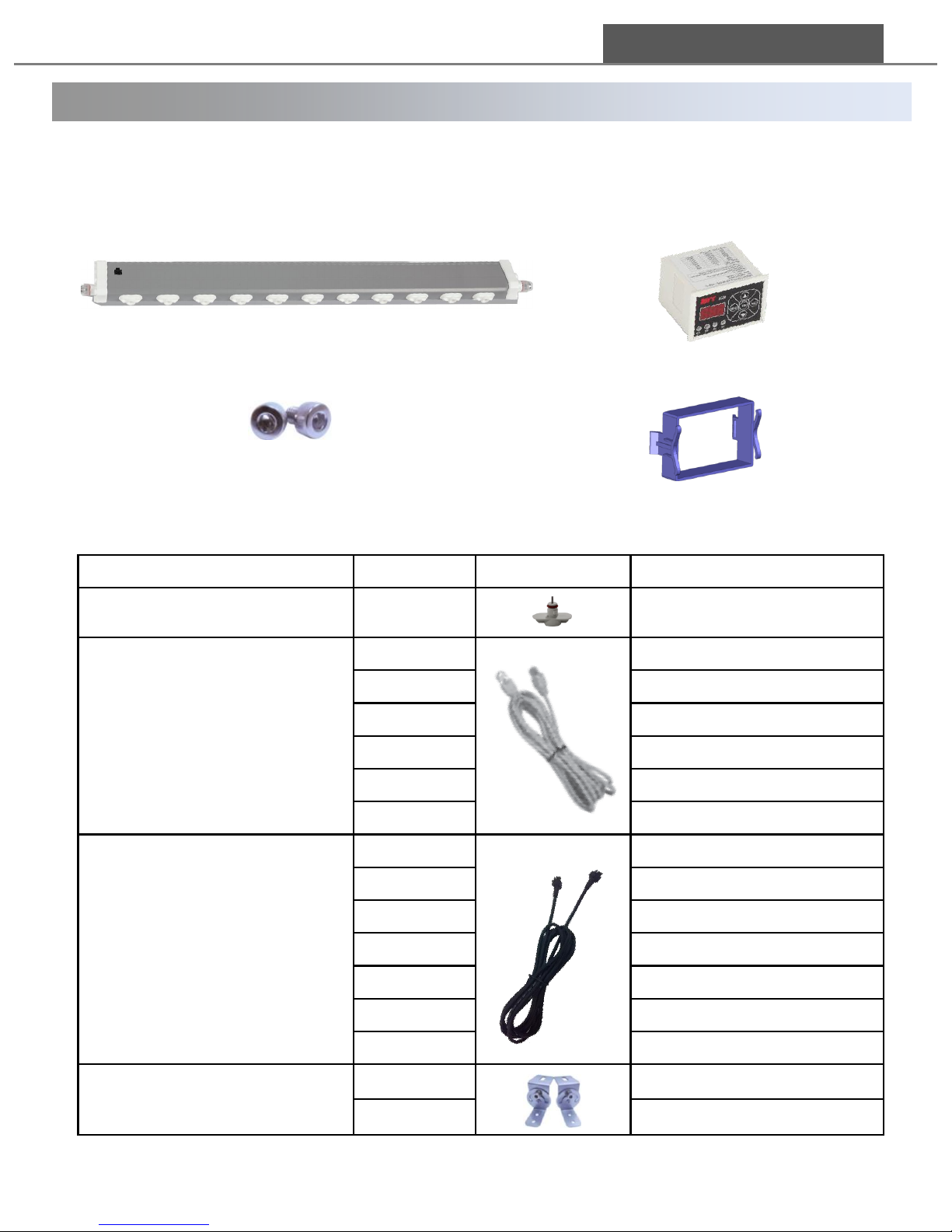
① Main body(power supply embedded)
② Fixing screws
※ Contact to the seller for customizing
(Basic hexagon head bolt M4X6mm)
Package
Options
1.5 Package Contents
DONG IL TECHNOLOGY LTD
(2) Controller Package
ASM-P Bar사진 삽입
② Controller Bracket
(1) BAR Package
① Controller
Page 8
1. 3 Part Names
8
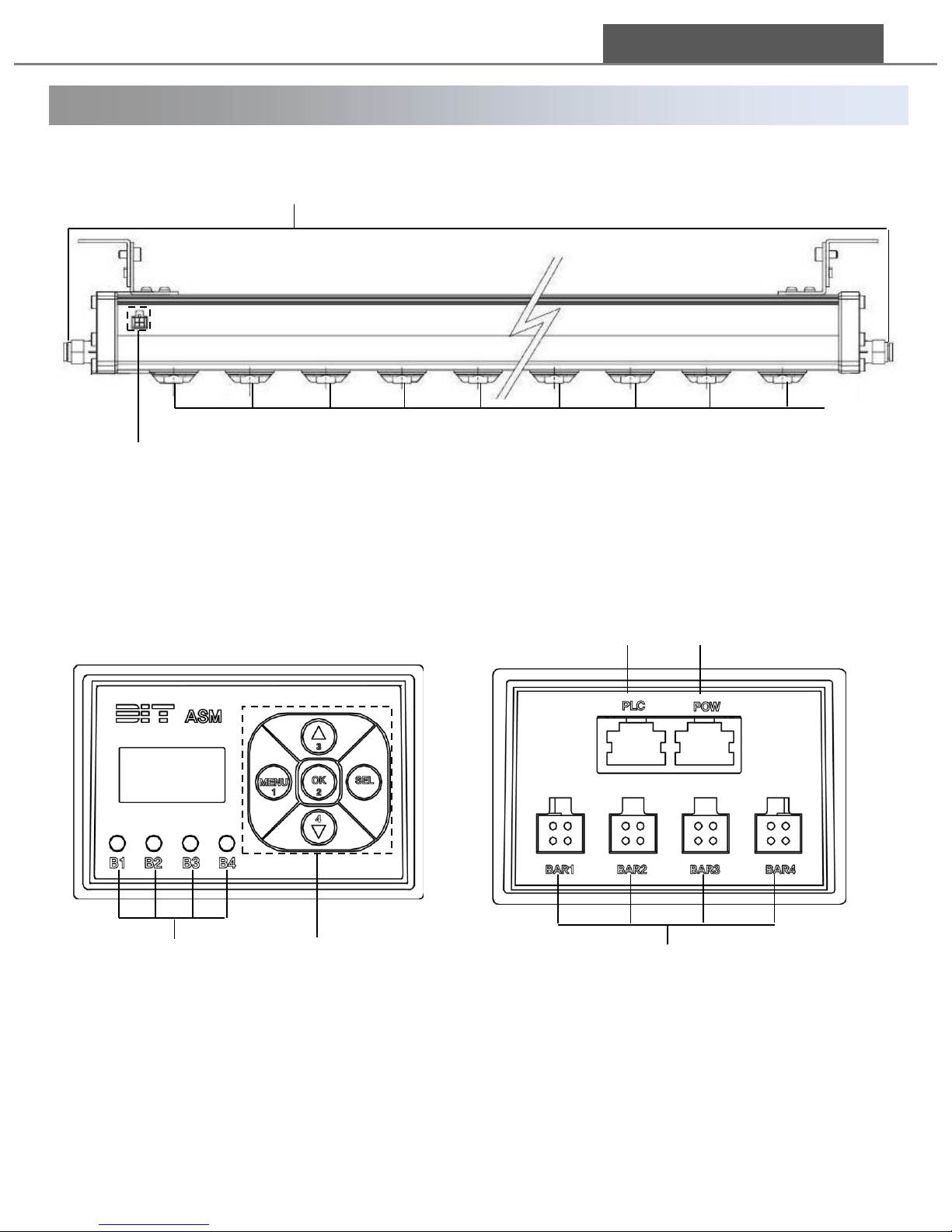
1.6 Part Names
DONG IL TECHNOLOGY LTD
① Air feeding entrance
② Ion emitters
③ Controller Connector (4pin)
①
②
③
<BAR>
① DISPLAY
② Status Display LED of Ion Bars
③ Menu Buttons
④ Bar Connectors (4pin)
⑤ PLC Connector [RJ45(8pin)]
⑥ Power Connector [RJ45(8pin)]
①
②
③
④
⑤
⑥
<Controller>
Page 9

3. 2 설치 상 주의사항
Please be well informed of the cautions below before installation.
Safety
. To avoid the risk of electric shock or product malfunction, keep fingers and metallic
objects away from the unit during operation.
. Make sure that there is adequate ventilation when using the Unit in an enclosed space
because static elimination using Corona Discharge method generally generate a small
quantity of ozone.
. To avoid the risk of electric shock, be sure to turn the power off during the maintenance.
. To avoid the risk of injury, do not touch the emitter pin directly with your hands.
. Disconnect from power supply and remove all the air in the unit before installing or moving.
. To avoid explosion, do not install the Unit in a place surrounded with volatile material or a
lot of particles.
Power supply
. Use a DC power supply at voltage of 24V+-10%
. Be sure to use a stabilized DC power supply.
Installation
. Don’t use any other parts not enclosed in the package.
. Do not install in regions affected by strong electric magnetic fields.
. Keep appropriate distance between two units to avoid mutual interference (refer 10page)
. Do not connect power cable to PLC connector.
. Be careful not to apply excessive force on air feeding entrance or side cover, especially
when installing the Unit vertically.
Air
. Remove impurities like water or oil from the air in compressor by using filters or
air dryers before use.
. Install the unit after making sure that there is no foreign material in the air passage.
Non-observance of the above and in this manual may lead to injury or product
malfunction. DIT doesn’t take any responsibility for the damage if the Unit is used in a manner
that differs from the specification in this manual or if the Unit is modified by yourself
9
1.7 Cautions
Warning!!
DONG IL TECHNOLOGY LTD
Page 10
3. 1 설치 위치 선정시 고려사항
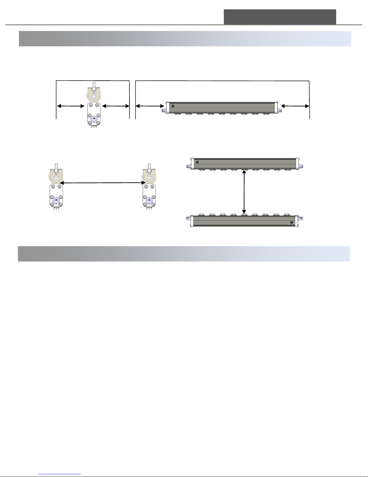
Provide enough space between the static elimination bar and surrounding walls as
shown in the figures below.
If two ASM-P units are used, refer to the following illustration and separate the static
elimination bars properly.
Keep at least 20cm distance between the Unit and the static charged object.
400mm
<unit1> <unit2>
10
2.1 Installation Location
2. 2 Purging and moving into CR(Clean Room)
Moving the Unit into clean room
We recommend doing the below process before moving the Unit into a clean room.
1) Remove the wrapping paper outside the clean room.
2) Clean the outside of the plastic wrap with cleansing solution.
3) Moving the Unit into clean room using a pass box.
4) Remove the plastic wrap before installation.
※ If you have your own process for Clean Class, you can apply it.
400mm
200 200 200 200
<unit1>
<unit2>
2. Installation
Purging
ASM-P series is packaged after purging in our clean room to remove dust. However, if
needed, execute purging process according to the below.
1) Install the unit.
2) Feed the Unit CDA or N2 gas at about pressure of 3Bar(0.3Mpa)
3) After purging for a period of time, check the particle level with a counter to make
sure that it is suitable for Clean Class.
DONG IL TECHNOLOGY LTD
Page 11
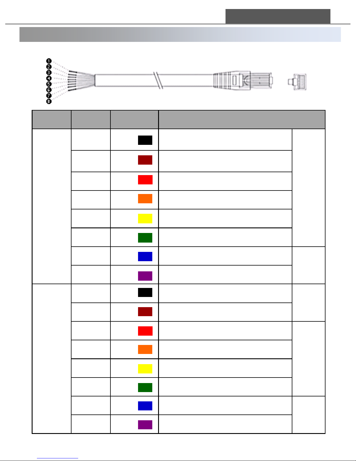
1111
Usage
PIN No.
Color
Connection & Usage
Power
cable
①
Black
Power Supply Ground, Field Ground
For
power
supply
②
Brown
Power Supply Ground, Field Ground
③
Red
Power Supply Ground, Field Ground
④
Orange
+24 DC Power Supply
⑤
Yellow
+24 DC Power Supply
⑥
Green
+24 DC Power Supply
⑦
Blue
Communication TX(-) Signal
RS485
Commun
ication
⑧
Violet
Communication TX(+) Signal
PLC
cable
①
Black
PLC Circuit BAR1 Ion On/Off
PLC
On/Off
②
Brown
PLC Circuit BAR2 Ion On/Off
③
Red
PLC Circuit BAR1 Ion Alarm Signal
PLC
Alarm
Signal
④
Orange
PLC Circuit BAR2 Ion Alarm Signal
⑤
Yellow
PLC Circuit BAR3 Ion Alarm Signal
⑥
Green
PLC Circuit BAR4 Ion Alarm Signal
⑦
Blue
PLC Circuit BAR3 Ion On/Off
PLC
On/Off
⑧
Violet
PLC Circuit BAR4 Ion On/Off
< Wiring Diagram>
DONG IL TECHNOLOGY LTD
2. 3 Wiring diagram
Page 12
12
2. 3 Wiring Diagram
Connection when not using PLC and RS-485
1) Connect the black, brown and red cables to a power and field ground.
2) Connect the orange, yellow and green cables to DC 24V.
3) To avoid short, cut the blue and violet cables shortly and tapping them with deliberation
DONG IL TECHNOLOGY LTD
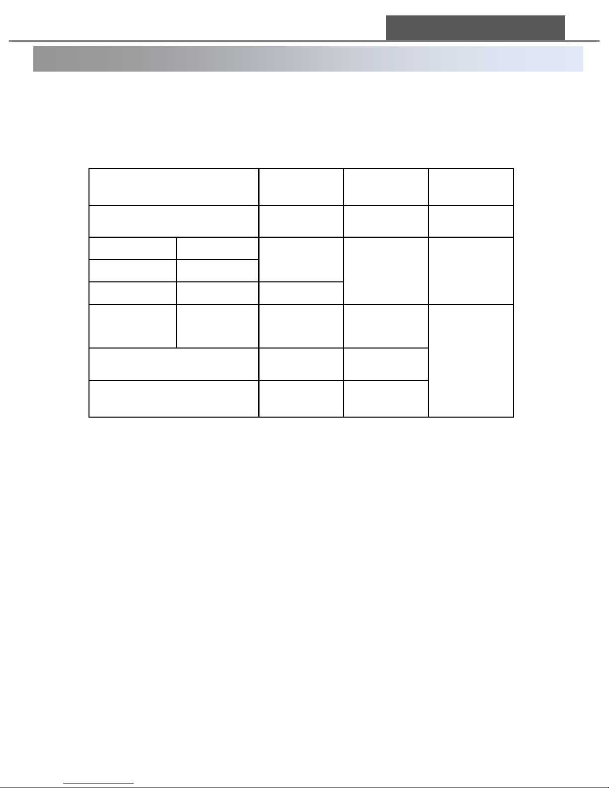
Operation status
Display
sign
LED
lighting
PLC Alarm
Disconnection to Ionizer
nc#
Lights-out
High
Ion On
PLC On
Io#
Green light
Low
Ion On
PLC off
Ion off
PLC On
Po#
Ion off
PLC off
IF#
Green light
blinking
High
HVPS failure/malfunction
Er#
Red light
Alarm for Emitter Tip
Cleaning Period
tc#
Green light
‘#’ sign means each port from B1 to B4.
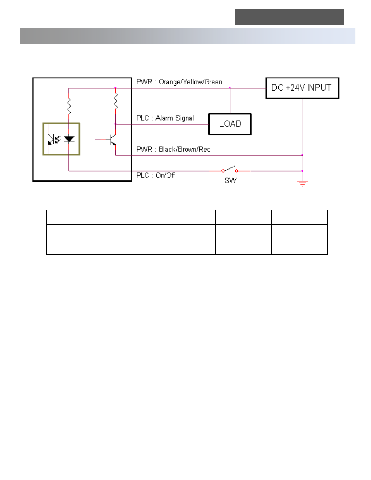
Connection when using PLC
1. Connect the power cable in the same way as described above (Connection when not using
PLC and RS-485) .
2. Distinguish each alarm cable and on/off cable per bar number when using PLC
(Please refer to <PLC cable according to the number of connected bars> in the next page).
1) Connect the on/off cable to the ground, the same point of the black, brown and violet
cables, which makes PLC work.
2) If you open the on/off cable, PLC doesn’t work.
(Please refer to the <ASM-P Series PLC Circuit Diagram> in the next page)
3) The alarm signal cable is for an alarm signal.
- Normal condition: 0V output
- Abnormal condition: 24V(4.2mA) output
- Setting Load: Set the output current under 100mA
Page 13
13
2. 3 Wiring Diagram
Connection when using an adaptor
1) Connect the black, brown and red cables to the adaptor (-)
Make sure that either one of the lines should be connected to an earthed part of
the machine.
2) Connect the orange, yellow and green cables to the adopter (+)
3) To avoid short, cut the other 2 cables shortly and tapping them with deliberation.
DONG IL TECHNOLOGY LTD
<ASM- P Series PLC Circuit Diagram>
* Refer to the above color list for wiring when connecting
bars.
BAR
BAR 1
BAR 2
BAR 3
BAR 4
On / Off
① Black
② Brown
⑦ Blue
⑧ Violet
Alarm Signal
③ Red
④ Orange
⑤ Yellow
⑥ Green
<PLC cable according to the number of connected bars>
Page 14
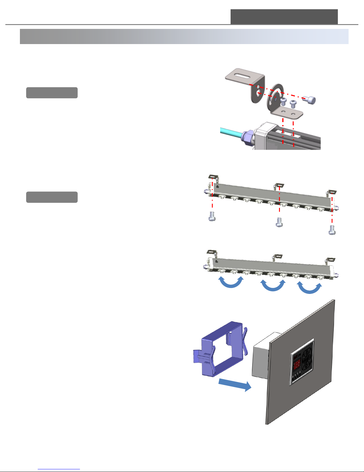
② Fix the main body with M5 screws.
Before fixing the main body,
make sure that you comply
all the precautions (p9.) and location guide(p.10)
2.4 Installing and connecting main body
Installation order
① Assemble the brackets firmly into a main body
If you fix the Unit without using the brackets in package,
be careful the weight not to be applied on the side
cover, which can result in air leakage.
14
③ You can change main body angle up to 180
degree.
DONG IL TECHNOLOGY LTD
④ Fix the controller on the external panel of
equipments or flat spot.
Warning!!
Warning!!
Page 15
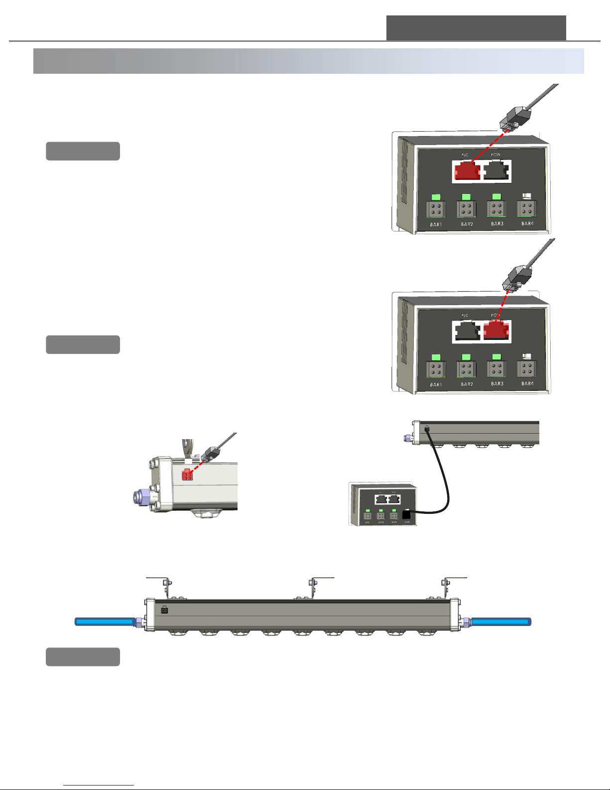
15
2.4 Installing and connecting main body
⑧ Feed the air
6 mm diameter tube is used in ASM-P. Connect tube by pushing it through
air fitting until you hear ‘click’ sound.
DONG IL TECHNOLOGY LTD
⑦ Connect a bar and a controller using 4pin
connector cable.
⑤ Connect RJ-45 power cable (A or B types) to
power connector of the controller by pushing the
cable until you hear ‘tic’ sound.
∙ Make sure that you understand the connection
diagram(P.11) and make connections
accordingly.
∙ If the power cable is connected to PLC
connector, the device can be damaged.
∙ For guaranteed performance, make sure that
GND line of the power cable should be earthed.
Warning!!
⑥ Connect the PLC cable to PLC connector of
controller by pushing the cable until you hear ‘click’
sound.
∙ Make sure that you understand the connection
diagram(P.11) and make connections accordingly.
Warning!!
∙ Make sure that air pressure should be lower that 0.5 Mpa.
∙ Air pressure lower than 0.3 Mpa is recommended.
∙ Flow rate and cleanness of supplied air is crucial for performance and
cleaning cycle of the device.
Warning!!
Page 16
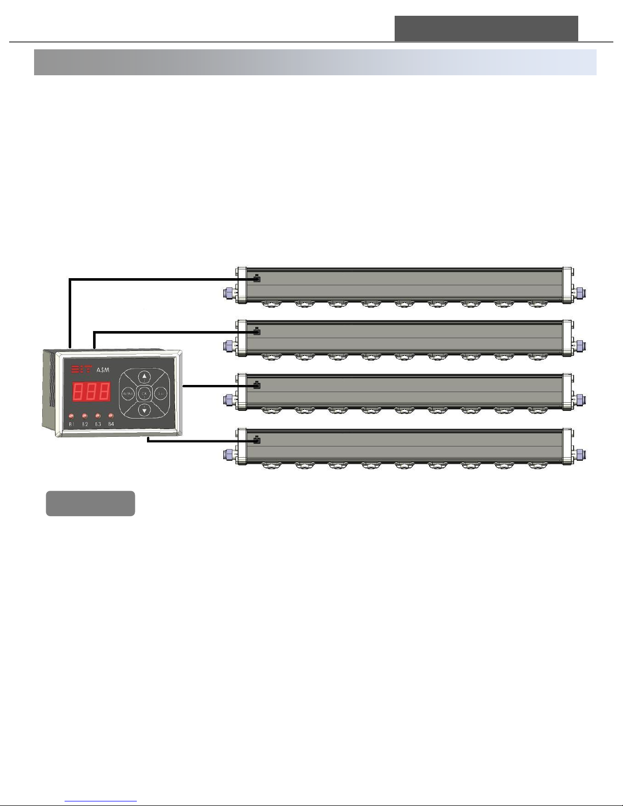
2. 5 Connecting multi bars
16
Up to 4 bars can be connected to 1 controller in ASM-P Series.
∙ Electric power: Electric power(DC24V) is transferred to bar via controller.
HVPS of Ion bar supplies high voltage to the emitter pin.
∙ Telecomm: Controller collects the status of bars and transfers it through RS-485.
[Telecomm Information: status of alarm and tip-cleaning]
[Telecomm Control Item: Ion on/off, Ion output frequency, Ion balance]
∙ If the power cable is connected to PLC connector, the device can be damaged.
∙ If you are to use cables other than ones provided by DIT, please consult us or
our agency.
∙ When connecting multiple bars, make sure that sufficient air and power are
supplied.
∙ Do not contact 4pin connector cable with a bar except for the connected point.
∙ Do not disconnect 4 pin connector cable from controller when it is powered.
It causes the product malfunction.
DONG IL TECHNOLOGY LTD
Warning!!
Page 17

2. 6 Check list after installation
17
Recheck the below list before operating the Unit.
(1) Make sure that power and air supply are properly connected. Check if proper
amount of air flow and power are supplied to the unit. Excessive or deficient
amount of air and power may cause damages to the device.
(2) Check operation environment that may cause malfunction, failure or shorting the
life of the device, such as strong magnetic or heat sources.
(3) Check if there are any metallic objects in the vicinity of the device,(<5 cm), or
within the operating distance. Metallic objects nearby hinder ion generation;
metallic objects within the operating distance block ion moving toward targets for
static control.
(4) Check if emitter is installed correctly. Operation without the emitter may seriously
damage the device or cause malfunction of the device.
(5) Check if the device is loaded with excessive weight or subject to shock. Excessive
load or shock to the device may cause serious damage such as malfunction or air
leakage from broken/bent air duct.
Our ASM-P Series are ionization devices using Corona Discharge method. Ion
emission and ion balance are subject to operation environment, please make
yourself familiar to the device, instruction, and cautions before using the device.
DONG IL TECHNOLOGY LTD
Page 18
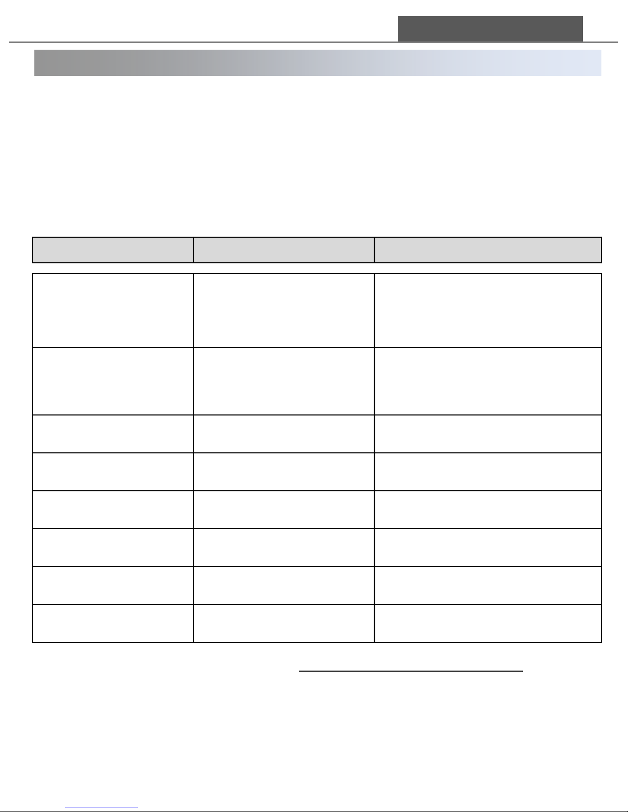
3. Settings
3. 1 How to set values
18
Operation
How to control
Controllable items
Entering Concurrent
Control Menu
Press “Menu” at a standby
screen
Ion / FrE* / bAL**/ tiP/ PAS
Com
Int
Adr
Entering Individual
Control Menu
1. Press “SEL”
2. Press a button of the
bar to control.
3. Press “OK”
Ion
tiP
bAL*
FrE **
Selecting control items /
Changing setting values
Press “▲” or “▼”
Entering a control item
list
Press “OK”
Setting and saving a
value
Press “OK”
Returning to the initial
screen
Press “Menu” on the Menu
mode
Moving a cursor to
upper digit
Holding “▼” and press “▲”
Adr, bAL, FrE, PAS
Moving a cursor to lower
digit
Holding “▲” and press “▼”
Adr, bAL, FrE, PAS
DONG IL TECHNOLOGY LTD
Concurrent Control Menu – Use to control all the bars connected to a controller
concurrently.
Individual Control Menu – Use to control an specific bar connected to a controller.
Saved values on the Individual Control Menu mode is not affected even if the values are
changed on Concurrent Control Menu mode later.
•*, ** Menu is activated only when ASM-A/ASR-A(AC Pulsed ionizers) is
connected.
• * Set the output frequency under 30Hz when using ASR-A Series.
Page 19
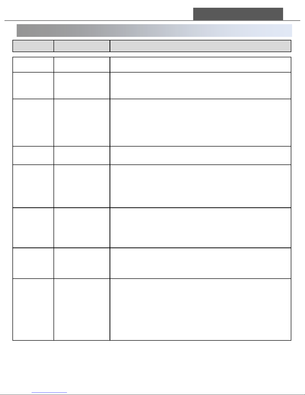
3. Settings
3. 2 Explanation on menu options
19
Menu
Explanation
Notes
Adr
Setting Address
Assigning “A01” – “A10” is allowed (up to 10 units).
Ion
Ion On/Off
When ion output is “oFF”, alarm LED changes to green and.
“IF#” is displayed on FND.
FrE*:
Setting
Frequency
This menu is not activated for ASM-P.
Frequency output may range from 1.0 to 60.0.
“1.0 ~ 10.0”: adjustment possible by 1.0
(increase/decrease)
“10.0 ~ 60.0”: adjustment possible by 5.0
(increase/decrease)
Bal**
Setting Ion
Balance
This menu is not activated for ASM-P.
Ion balance may range from 35.0 to 65.0.
tIP
Setting Emitter
Pin Cleaning
Period
If “Yes” is chosen to start cleaning cycle, “tc#” is displayed,
when the end of cleaning cycle is reached.
Once the pins are cleaned, reset the cleaning cycle.
Cleaning cycle can be increase by week (one week as a unit;
up to five weeks); t01~t52
PAS
Setting
Password
When the password is on, you need to enter the old
password to enter the main “Menu” for a new password
setup.
Password can be a three digit number, any number between
000 and 999.
Com
Setting
Communication
Speed
Communication Speed is measured in BPS(bit per second)
Selection can be made among seven speeds shown below.
2.4k /4.8k / 9.6k / 19.2k / 38.4k / 57.6k / 115k
Int:
Restoring initial
factory settings
Factory setup is as follows.
Adr : “A01”
Ion : “ on”
FrE : “30.0”
bAL : “50.0”
PAS : “oFF”
Com : “ 9.6”
tIP : “no“
DONG IL TECHNOLOGY LTD
Page 20

4. 1 Necessity of maintenance
20
4. Maintenance
DONG IL TECHNOLOGY LTD
Necessity of emitter pin cleaning and emitter replacement
In general, when static controllers are continuously in operation for a long period,
dust and dirt are accumulated around the emitter pin, called “fuzzy-ball’.
Depending on operating environment, ‘fuzzy-ball’ grows to block normal operation
and results in deterioration in performance of static controller.
An emitter pin (inside a emitter) is a sharp, pin-shaped object, made from tungsten.
ASG-P series produces ions using Corona Discharge method . Thus, during an
operation, high voltage is applied on its emitter pin, which rounds the sharp pin
away as the time goes on. A rounded emitter pin cannot produce ion as well as the
sharp one.
For these reasons, emitter and emitter pin should be cleaned and replaced
periodically.
If not cleaned, and replaced properly, worn-out emitter pin with fuzzy-balls, may
deteriorate the quality and performance of your production. Make sure that emitter
(and emitter pin) should be cleaned and replaced on a regular basis.
Recommended cleaning cycle under the circumstance below : Every 6 months
∙ Temperature : 22 ℃[a higher temperature may lengthen the cycle]
∙ Humidity : 50%[a higher humidity may lengthen the cycle]
∙ Clean Class : 10,000 Class [a lower Class index may lengthen the cycle]
∙ Quality of Supplied Air : CDA[purer air may lengthen the cycle]
※ The conditions listed above are for general environment, Actual result may slightly
vary depending on the user’s working environment.
Six months cleaning cycle is based on test conditions used by DIT. Please compare
DIT’s conditions and your working environment and adjust it and set up cleaning cycle
accordingly.
Page 21
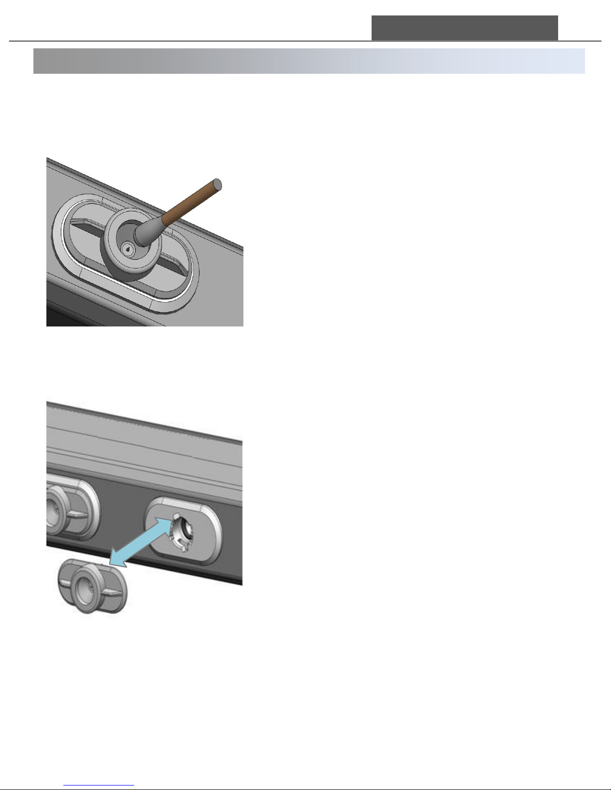
4. 2 How to clean and replace emitters
How to clean an emitter
How to replace an emitter
① Prepare soft brush or cotton swab with alcohol.
(No acetone)
② Power off the device and stop the air input.
③ Wipe out the white ‘Fuzzy ball’ on the end of the
emitter pin softly enough not to damage
or scratch it.
④ Power on the device and feed the air
⑤ After 5 ~ 10 minutes, check the device
performance with and measuring instrument.
21
① Prepare a new emitter for replacement.
② Power off the device and stop the air input.
③ Rotate the emitter assembled in the Unit
counterclockwise
④ Pull the emitter to separate it from the Unit
⑤ Insert a new emitter and rotate it clockwise to
fix it firmly.
⑥ Power on the device and feed the air
⑦ After 5 ~ 10 minutes, check the device
performance with and measuring instrument.
DONG IL TECHNOLOGY LTD
Page 22
Trouble Shooting
22
※ If you cannot solve the problem with the direction above or have other problems
not described above, please call the manufacturer or leave a message on our
website(www.dit-ind.com).
Quality assurance team : 82.31.299.5466
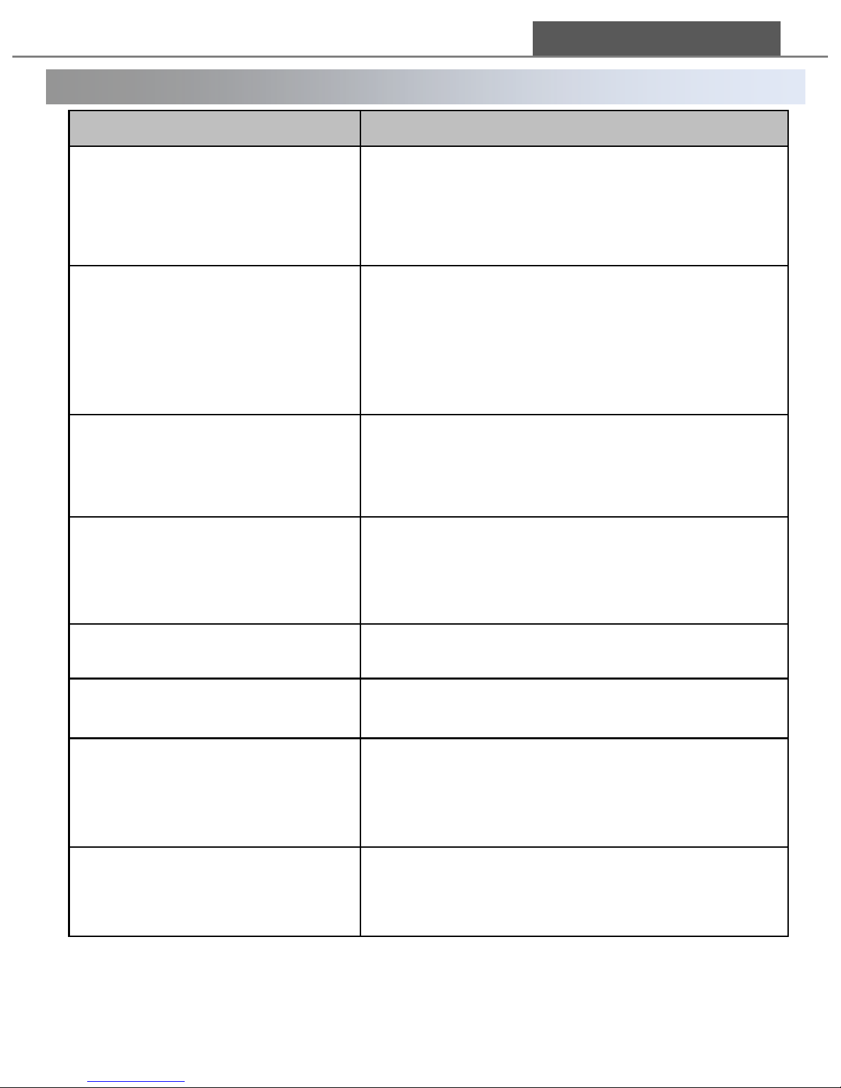
Problems
Check Points
FND is not displayed
1) Check that the power cable is connected
correctly.
2) When it dose not work even though the
cable connection is correct, contact to
our sales agent..
Alarm LED is blinking in red/
Er1/2/3/4 is shown on
standby screen
(Error message is displayed on
FND)
HVPS/Circuit error or an error due to Protection
circuit operation.
If it is the same even after re-booting, contact
to our sales agent.
Alarm LED is blinking in green
Ion off.
Check the status of ion generation on a menu.
Ion balance is swing between
+ and -
1) Some swing is natural because of Auto
Balancing function
2) Clean the emitter pin or replace the emitter
Slight unknown smell during
operation
Normal state caused by high voltage discharge
Smell of burning during
operation
1) Turn off the power immediately.
2) Contact to our sales agent.
“TC” is displayed on FND
It alarms for tip cleaning period.
Change the settings of tip cleaning on the
menu mode or the specific menu option.
“NC” is displayed on FND
NC1,2,3,4: Ion Bar connection error.
Check that the connection is correct.
DONG IL TECHNOLOGY LTD
Page 23

Warranty
We, Dong Il Technology Ltd. Manufactured this product under a strict
quality control system and warrants it for1 year of period from the
shipment date.
However, we don’t have any responsibility for
1) Any damage if the product is used in a way different from that is
explained in this manual or remade by users arbitrarily.
2) Any damage led by improper usage. We recommend the installation
circumstances in this manual, but that is just a recommendation
and users are responsible for understanding the product’s
specification and judgment of suitability of usage.
3) Direct or indirect damage led by the product malfunction.
DONG IL TECHNOLOGY LTD
28, Namyang-ro 930beon-gil, Hwaseong-si, Gyeonggi-do, Korea
Tel 031-299-5453 Fax 031-357-2610
 Loading...