

Page 1
Instruction Manual
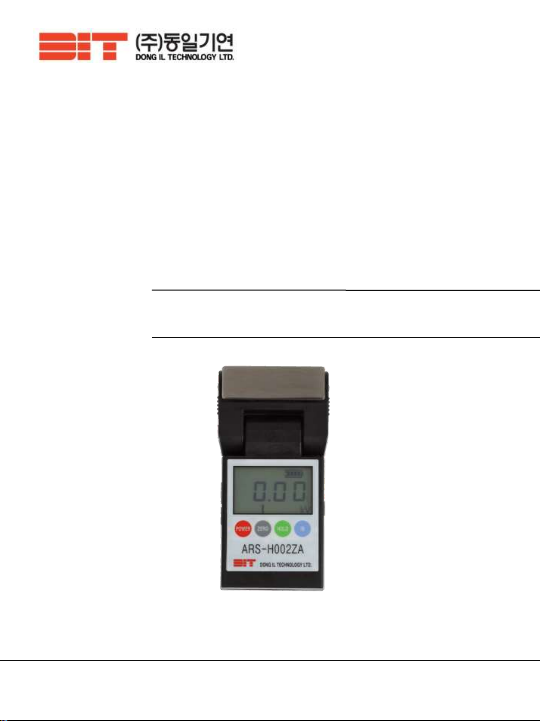
HAND-HELD ELECTROSTATIC VOLTMETER
ARS-H002ZA
※ Read this instruction manual before using the product in order to achieve maximum
performance.
※ Keep this instruction manual within your reach after reading so that it can be used at any time.
※ Warranty is on the last page of this manual. Please read the contents and keep it carefully.
28, Namyang-ro 930 beon-gil, Hwaseong-si, Gyeonggi-do, Korea
Tel 82.31.299.5453 Fax 82.31.357.2610
Page 2

DONG IL TECHNOLOGY LTD
CONTENTS
1. Features …………………………………………………………………………3 Page
2. Specification ……………………………………………………………………4 Page
3. Package contents………………………………………………………………5 Page
4. Parts name and functions……………………………………………………6 Page
5. Dimension ………………………………………………………………………8 Page
6. Performance ……………………………………………………………………9 Page
7. Operating Instruction ………………………………………………………10 Page
7.1 Power supply[Battery use]
7.2 Measuring set-up
7.3 Setting zero point adjustment
7.4 Electrostatic mode
8. Remote monitoring system by a software ……………………………15 Page
8.1 Installation and connection of monitoring program
8.2 Monitoring program method
8.3 Case of disconnecting to monitoring program
9. Attention………………………………………………………………………16 Page
10. Trouble shooting ……………………………………………………………17 Page
11. Warranty………………………………………………………………………18 Page
7.5 Ion Balance mode
7.6 HOLD function
7.7 Automatic Power OFF function
2
Page 3
1. Feature
DONG IL TECHNOLOGY LTD
Welcome to become a customer of DIT.
Static electricity can cause lower production efficiency, such as
damage on circuit pattern of products, particle deposition and etc.
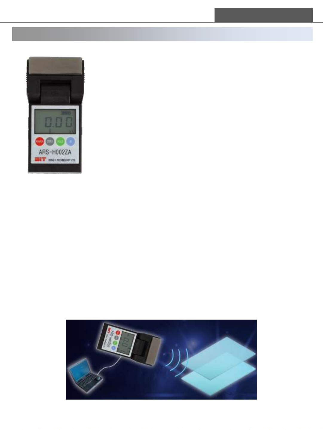
“ARS-H002ZA” is the portable voltmeter, which can monitor and
manage static electricity easily on production lines.
1) Detection of the electrostatic spot
2) Selecting the place for ionizer installation
3) Checking the Ion balance of ionizer and measuring static
charge
▶ Precision mode and Expansion mode
Precision mode detects static electricity from 0V to±2.00kV, and Expansion mode detects it
from ±2.00kV to ±20.0kV. Both modes are changed automatically during usage.
Resolution is 10V from 0V to ±9.99kV. When static electricity is under -10.0kV or +10.0kV,
the resolution is 100V. In case of Ion Balance mode, it is able to be displayed in unit of 1V.
▶ Rotary sensor head
ARS-H002ZA has a rotary head which makes convenient measurement in narrow space.
Also a sensing plate for ion balance is designed with rotary integrated structure,
so it is more convenient for use and storage of the product.
▶ Real time Monitoring System by PC
It is able to check the measured data in real time and save the data via USB port.
[Monitoring program is provided free of charge]
3
Page 4
DONG IL TECHNOLOGY LTD
2. Specification
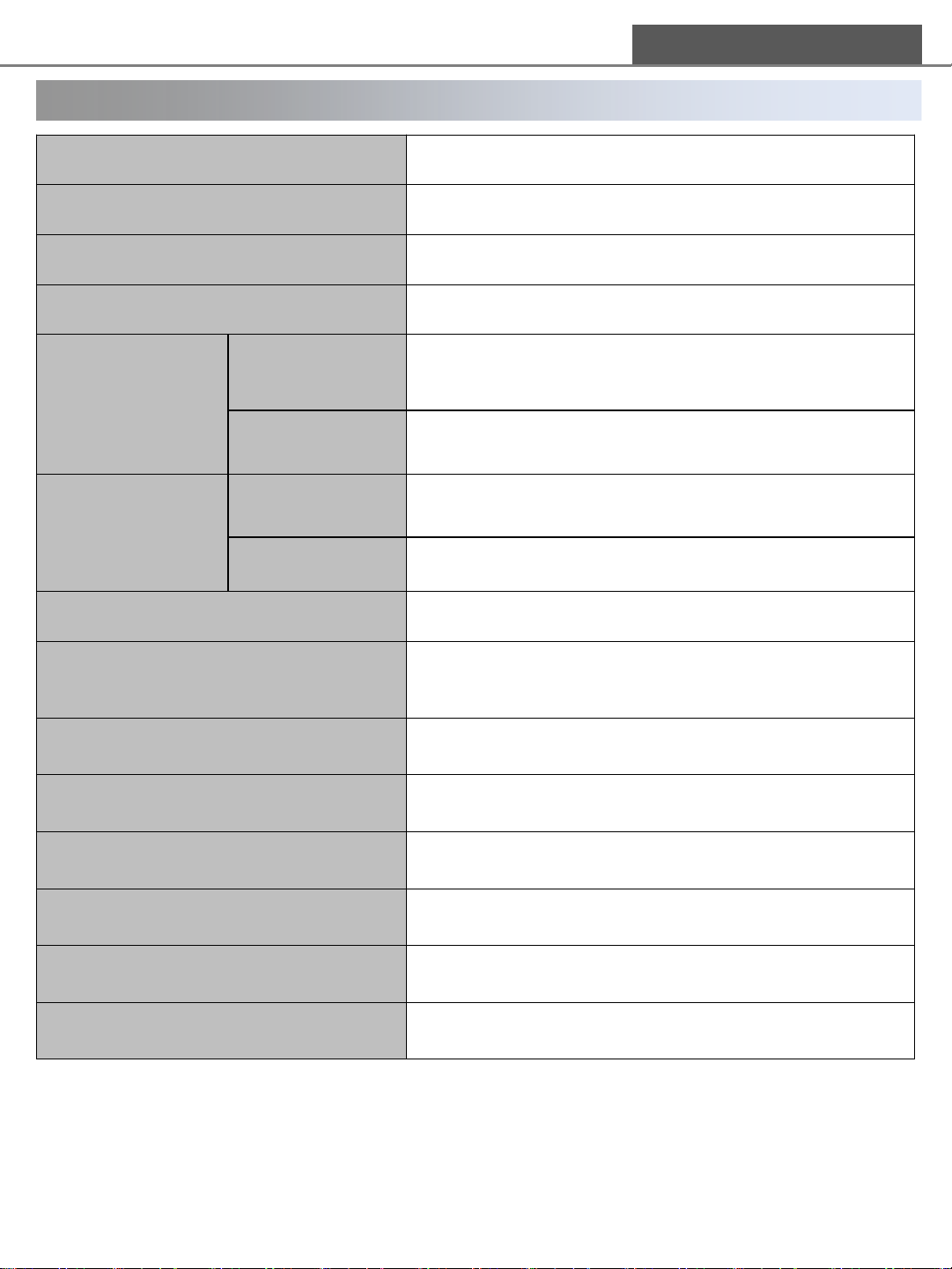
Dimension(Size) 134.0mm(L) x 68.6mm(W) x 26.0mm(H)
Input Voltage +9VDC ±10%(Alkaline battery use)
Sensor Oscillating Chopper Type (DIT)
Measurement Distance 25mm (±0.5mm) Fixed
Precision mode : ±2kV (±10%)
Electrostatic mode
Measurement
Range
Ion Balance mode ±300V (±10%)
Expansion mode : ±20kV (±10%)
(Auto change)
Electrostatic mode
Resolution
Ion Balance mode 1V
Response Time < 1sec.
Function
Display HTN-LCD[Digit and Gradation display]
Material Conductive ABS
Operating time Max approx. 30hours
Communication USB Communication
Ambient Temperature 10℃ ~ 40℃ (50~104℉)
-9.99 ~ +9.99 kV : 10V
-under 10.0kV or over +10.0kV : 100V
Automatic power OFF, Alarm for power OFF,
Zero setting, Electrostatic/Ion Balance mode,
HOLD function
Ambient Humidity 0~60%RH (Non-Condensing)
※ Specification can be changed without notice for performance improvement.
※ This product is only designed for 25mm(±0.5mm) distance detection. It is available to detect
for other distance, however performance is not guaranteed.
4
Page 5
DONG IL TECHNOLOGY LTD
3. Package contents
Please check the package contents before use.
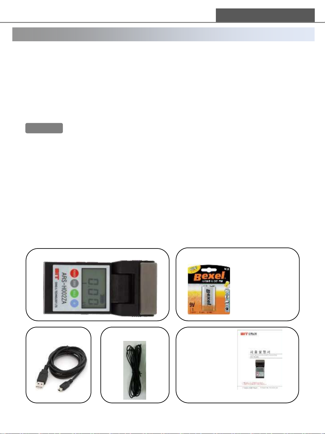
① ARS-H002ZA ------------------------------------------------------------------------------------------------1ea
Main body to detect static electricity/Ion Balance. LED of its head must be headed to the
object.
② Battery(6LF22, 6LR61 9.0V Alkaline battery) ---------------------------------------------------------1ea
The product is operated after a battery is put in the back of main body.
Warning!!
③ USB CABLE---------------------------------------------------------------------------------------------------1ea
1.2m USB cable is provided.
④ Earth CABLE--------------------------------------------------------------------------------------------------1ea
3m Earth cable is provided.
⑤ Instruction Manual -----------------------------------------------------------------------------------------1ea
Please read this instruction manual before using the product.
(1) Battery socket is disconnected to prevent battery consumption during distribution.
Please open the rear of the product and connect a battery to its socket.
(2) In case of long-time storage, power could not be supplied by discharged battery.
Please change a battery in this case.
(3) Please check the specification when to change a battery.
① ARS-H002ZA main body
③ USB CABLE
④ EARTH CABLE
② Battery
(6LF22 or 6LR61)
※ Battery is provided
in main body
※ This image could
not be matched for
real battery.
⑤ Instruction
Manual
※ Download instruction manual on web site.
5
Page 6
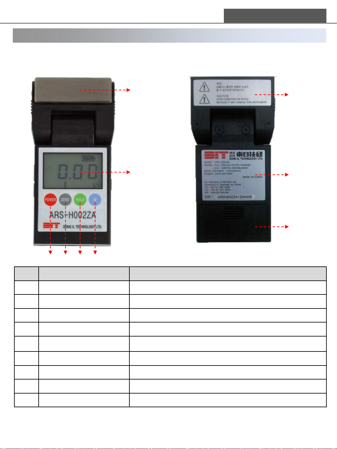
4. Parts name and functions
< Main body name and functions >
DONG IL TECHNOLOGY LTD
< Main body (front) >
①
②
< Main body(rear)>
⑦
⑧
⑨
⑤
⑥
④
③
NO Name Description
① SENSING PLATE Use for measuring ION BALANCE
② LCD PANEL Display measured value/Menu status/Power status/etc.
③ POWER BUTTON Turn power ON/OFF
④ ZERO BUTTON Set up to zero adjustment
⑤ HOLD BUTTON Hold the measured value
⑥ IB BUTTON Choose the Electrostatic mode or Ion Balance mode
⑦ LABEL 1 Caution
⑧ LABEL 2 Information of product and company
⑨ BATTERY BOX COVER Cover of the battery slot
6
Page 7
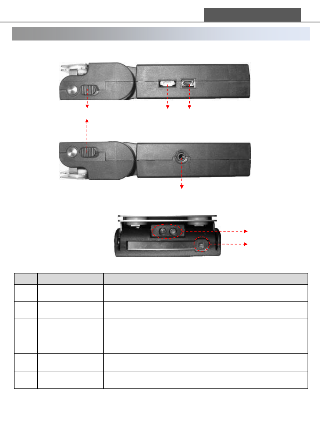
4. Parts name and functions
< Main body(left) >
DONG IL TECHNOLOGY LTD
④
① ②
< Main body(right) >
③
< Main body(upper) >
NO Name Description
⑤
⑥
① U.A.R.T External FIRMWARE terminal
② USB Terminal USB terminal for real time monitoring with PC
③ Ground Terminal Earth Cable terminal
④ Plate rotary button
⑤ LED for focusing
⑥ Sensing Hole Sensor for static electricity
Both buttons should be pulled down when rotating the plate for
measuring ion balance.
Two LED guide lights help position the voltmeter at 25mm distance
from a charged test object.
7
Page 8
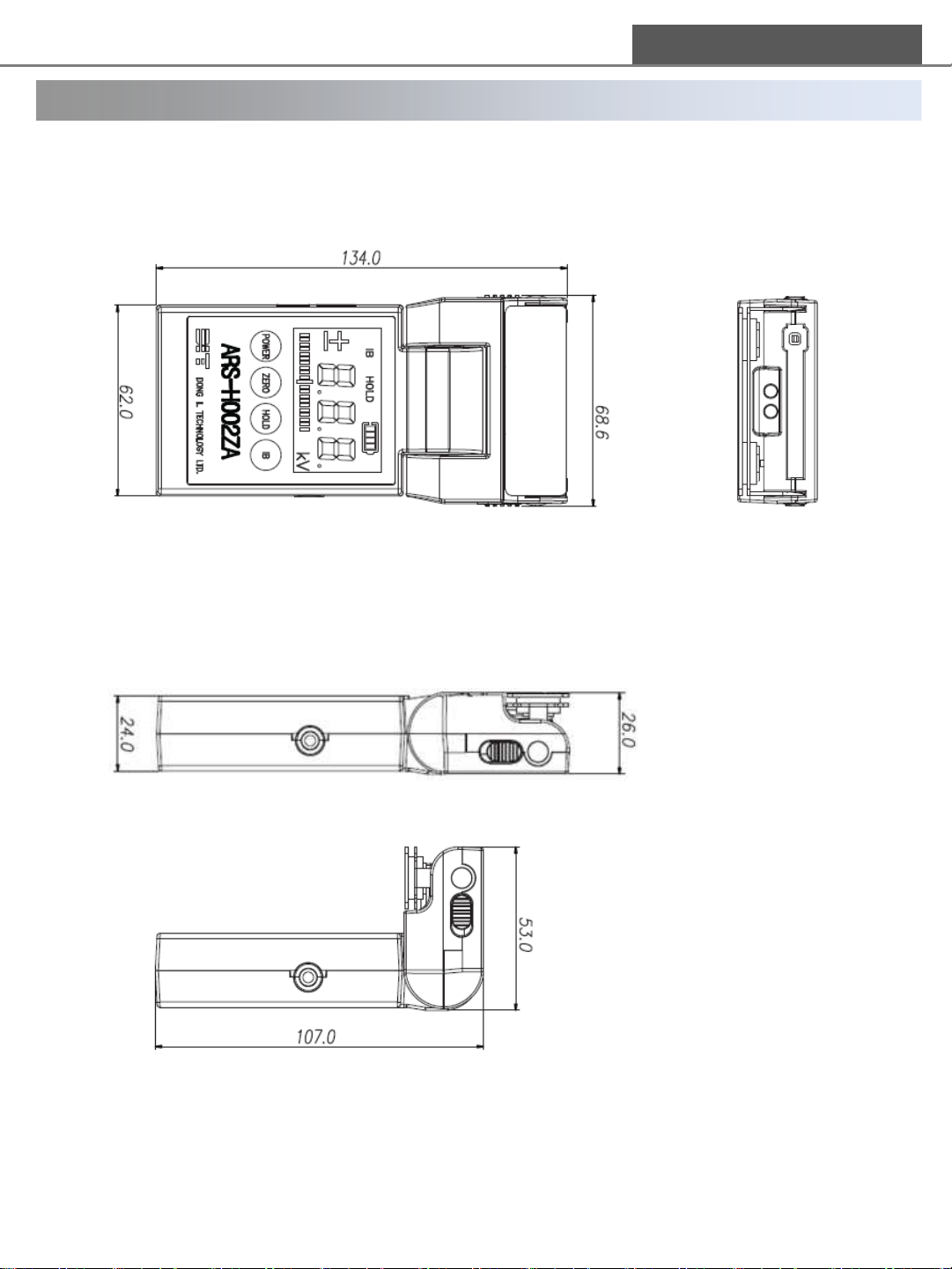
5. Dimension
< Front View > < Top View >
DONG IL TECHNOLOGY LTD
< Side View >
8
Page 9
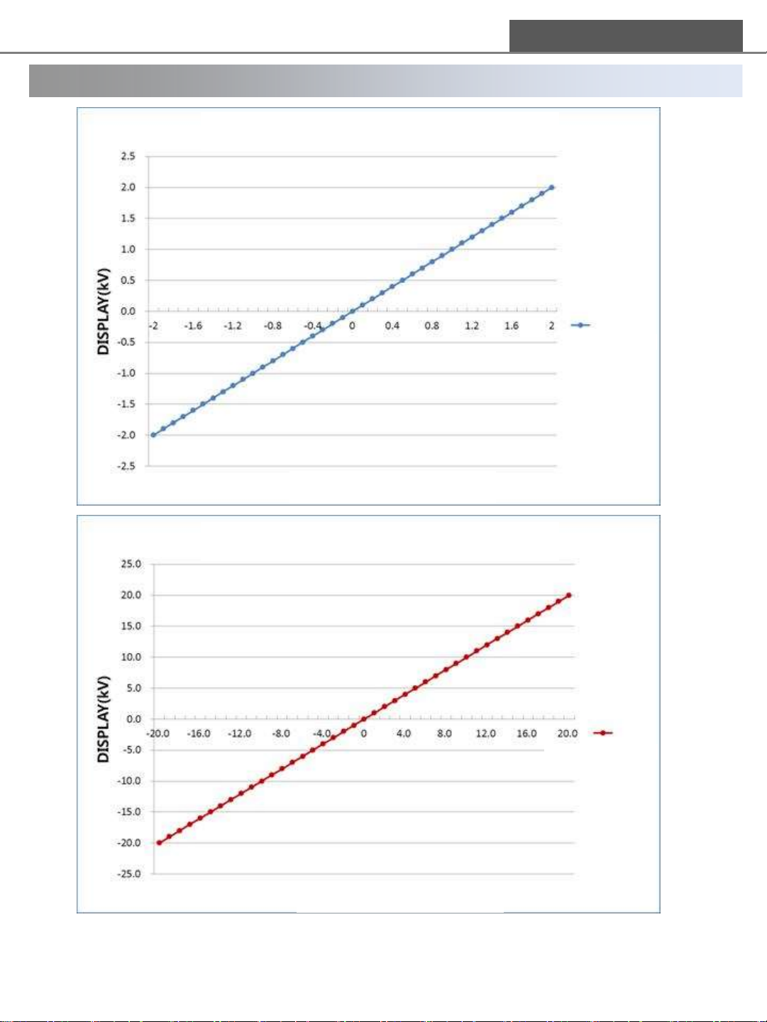
6. Performance
DONG IL TECHNOLOGY LTD
Display data according to charged voltage
Precision mode
Charged Voltage(kV)
Display data according to charged voltage
Charged Voltage(kV)
Expansion mode
9
Page 10
DONG IL TECHNOLOGY LTD
7. Operating Instruction
ARS-H002ZA is a portable electrostatic voltmeter, which is affected by environment.
Please read carefully the operating instruction below for an exact measurement.
7.1 Power supply[Battery use]
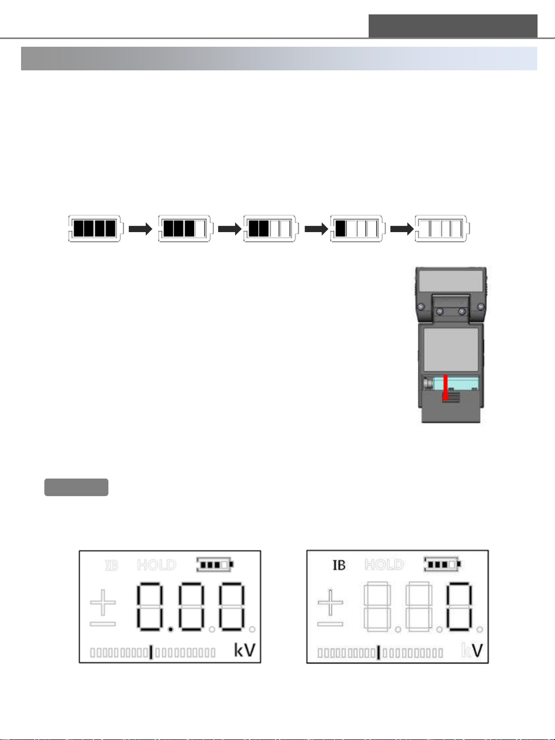
1) Battery socket is disconnected to prevent battery consumption during distribution.
Please open the cover of battery slot and connect battery to its socket before use.
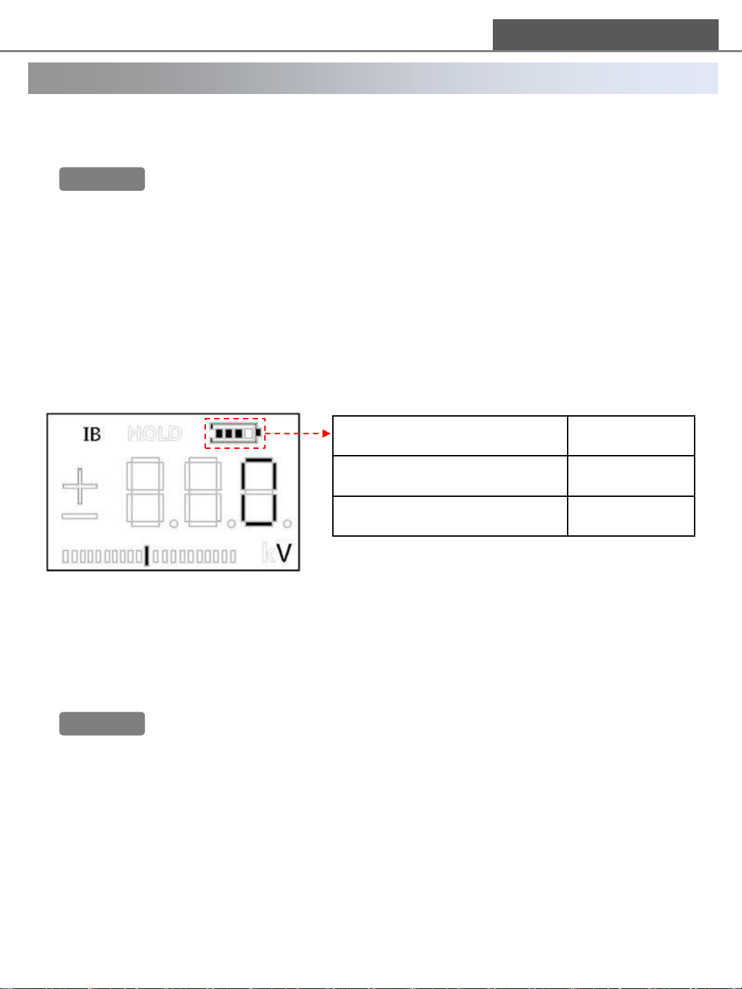
2) (Battery check)Power status is displayed on LCD as below. Please check the
power status periodically and change a battery when the battery is out.
3) The procedure for changing battery is as below.
① a cover of battery slot is on the back of main body. Pushing
the cover, pull it down. Then it opens.
② After taking a battery out of main body, disconnect the battery
to its socket.
③ Connect a new battery to the battery socket.
④ Put the battery in main body. At this time, arrange wires of the
socket inside the battery slot.
⑤ Close the cover of the battery slot.
Change a new battery
7.2 Measuring set-up
1) Connect main body to earthed objects with an ground cable.
2) It is recommended to wear Earth-Ring or ESD gloves to avoid a static electricity
from human body.
Warning!!
3) Press [POWER] button to operate the product apart from a charged test objet or ionizer.
4) Check the display is same as below after power on.
[Initial DISPLAY on Electrostatic mode] [Initial DISPLAY on Ion Balance mode]
If Earth cable is not connected, inexact values could be measured. Please use the
product after checking the product earthed.
10
Page 11
DONG IL TECHNOLOGY LTD
7. Operating Instruction
7.3 Setting zero point adjustment
In case that the initial value is not “0” though following the measuring set-up(7.2),
Please set zero point adjustment as below.
1) Setting zero point adjustment on Electrostatic mode
① Position a sensing hole toward non-electrostatic area.
② After pressing [ZERO] button, check if the value is changed to “0” on display.
2) Setting zero point adjustment on Ion Balance mode`
① Ion balance plate of head should be faced to the object.
② Touch an earthed wire on the plate, or remove remaining electric charge by finger
touch.
③ After pressing [ZERO] button, check if the value is changed to “0” on display.
Warning!!
1) If users set zero point adjustment during measurement, the measured value is not
accurate by distortion of reference zero point.
2) Setting zero point adjustment is not worked in below cases.([Zero] button is not
available) ① Out of range : over ±0.80kV[Electrostatic mode] / over ±100V[Ion
balance mode) ② During HOLD function
7.4 Electrostatic mode
This product measures the voltage or electrostatic level on objects with an integral sensor on
Electrostatic mode.
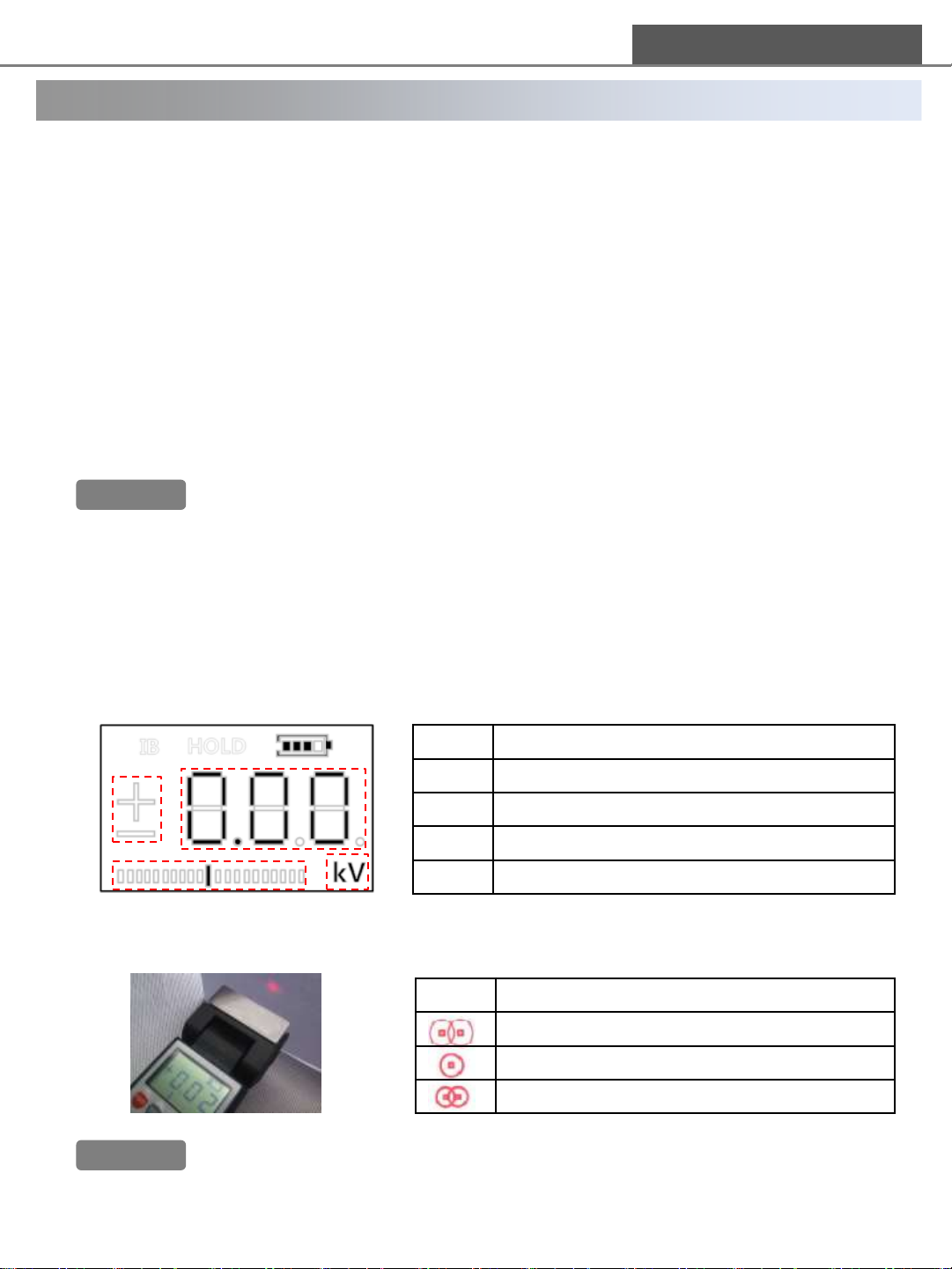
1) Check to set the electrostatic mode as below.
①
②
① Polarity of voltage
③
④
② Digit [-2kV~+2kV, -20kV~+20kV]
③ Bar graph [approx. 2kV/1 bar] [L(-)/R(+)]
④ Unit of measure [kV]
2) Place the device at right angle to test object as picture below.
Adjust the distance until two LED light marks become the one on the target.
Description
Warning!!
LED Measurement distance
Distance over 25mm
Right distance around 25mm
Distance under 25mm
An error of focusing LED could occur according to measuring angle and material of
the objects. Recommend to use aids such as ruler for exact measurement from
25mm distance.
11
Page 12
DONG IL TECHNOLOGY LTD
7. Operating Instruction
3) Check the measured value and polarity of voltage on DISPLAY.
Warning!!
7.5 Ion Balance mode
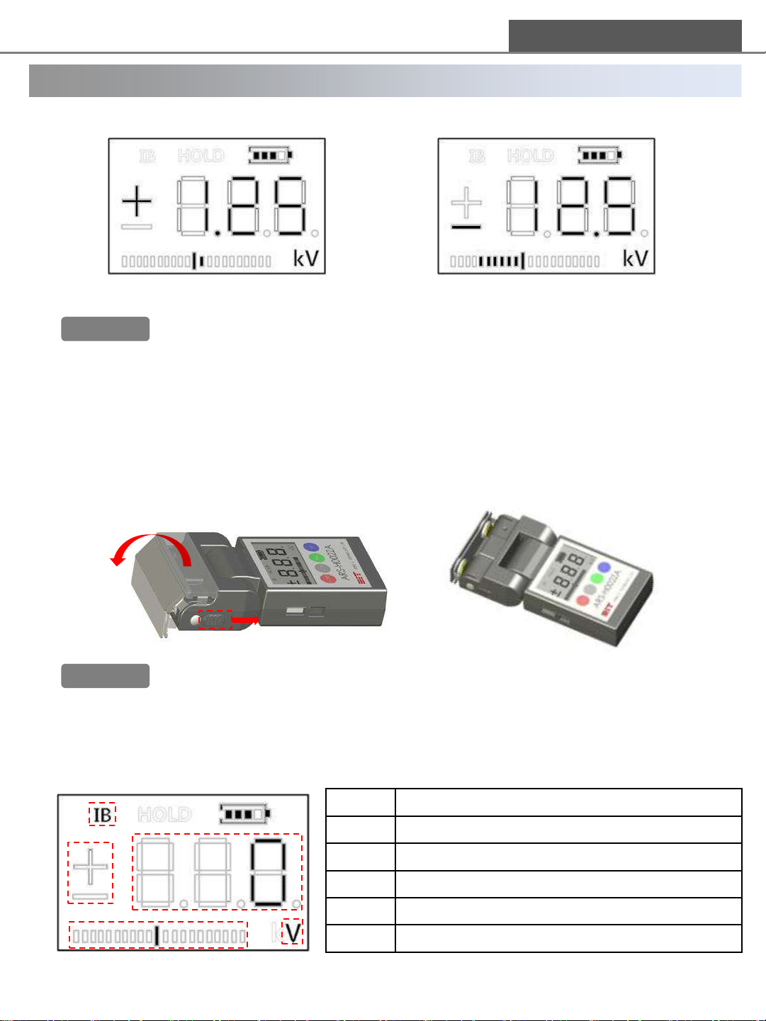
This product measures ion balance with sensing plate and an integral sensor in Ion Balance
mode.
1) After pulling down the plate rotary button(①) on both sides of head, move the
sensing plate(②) until above the sensing hole.
Warning!!
2) Check the setting for ion balance mode as below.
[ex1. measuring +1.25kV] [ex2. measuring -12.5kV]
When “HHH” or “LLL” is displayed, the level of static electricity is over measurable range.
In this case please stop measuring because integral sensor can be damaged.
※ HHH : over (+)voltage measurable range[+20kV], LLL : over (-)voltage measurable
range[-20kV]
②
①
1) Make sure to pull down the plate rotary button on both sides of head when moving
the sensing plate. Otherwise, fixing part for the sensing plate can be damaged.
2) Before measuring, the sensing plate should be moved to above the sensing hole.
Otherwise, the measured value could not be accurate.
①
②
④
③
Description
① Ion balance mode
② Polarity of voltage
③ Digit [-300V~+300V]
④ Bar graph [approx. 30V/1 bar], [L(-)/R(+)]
⑤
⑤ Unit of measure [V]
12
Page 13
DONG IL TECHNOLOGY LTD
7. Operating Instruction
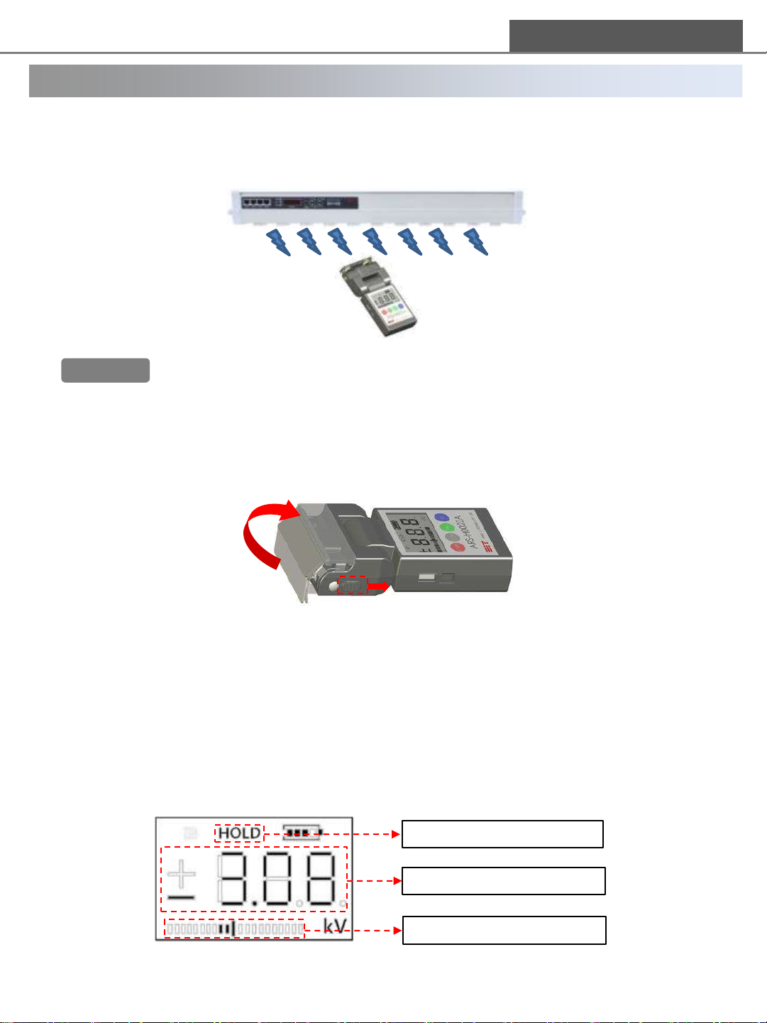
3) Position the sensing plate at ionizer to measure ion balance. Please approach the sensing
plate on ionizer to measure ion balance as much as distance between ionizer and object.
Ion balance value could be different according to the distance.
Warning!!
4) When measuring on Electrostatic mode, pull down the plate rotary button(①) on both
side of head. Please fold the sensing plate(②) up for exposing the sensing hole.
When “HHH” or “LLL” is displayed, the level of static electricity is over measurable
range.Please stop measuring. Otherwise, integral sensor can be damaged.
※ HHH : over (+)voltage measurable range[+300V], LLL : over (-)voltage measurable
range[-300V]
②
①
7.6 HOLD function [Electrostatic mode/Ion balance mode]
When the value on DISPLAY is hard to be checked, this function holds the value on DISPLAY.
So it is convenient to check the value even after changing the position.
1) Follow the operating instruction for measurement.
2) Press [HOLD] button on main body once when to measure the value.
3) When positioning the product with measurable distance, the value is fixed and “HOLD” is
displayed on LCD.
HOLD function status
Fixed value
Fixed bar graph
13
Page 14
DONG IL TECHNOLOGY LTD
7. Operating Instruction
4) After checking the fixed value, press [HOLD] button once again. Then, “HOLD” is
disappeared and the value and bar graph are changed in real time.
Warning!!
1) When the product is turned off on HOLD status, the fixed value is not saved.
2) If measure other objects on HOLD status, the value is not displayed on LCD. Please
measure after releasing HOLD status certainly.
7.7 Automatic Power OFF function [Electrostatic mode/Ion balance mode]
Power is turned off automatically with beep sound if not use for 5 minutes after measuring.
This function can be set by [HOLD] button on main body.
1) This function is the default setting for extension of battery life.
2) If user want to turn off this function, press [HOLD] button over 3 seconds.
Then, Automatic Power OFF function is turned off and it is displayed on LCD as below.
“Automatic Power OFF” on Not Blinking
“Automatic Power OFF” off Blinking
3) If not to use this function, the product keep continuously power-on until user turns off
power. Please note the battery charge status.
Status Display
4) If user want to reactivate this function, press [HOLD] button over 3 seconds.
Then, blinking of the battery charge status stops and Automatic Power OFF function is
reactivated.
Warning!!
1) In case of deactivating Automatic Power OFF function, check the battery charge
status because the product keep power on until user turns off by POWER button.
Battery could be discharged.
2) When turning on the product with deactivating Automatic Power OFF function,
this function is reactivated. If user want to deactivate it, repeat the steps above.
14
Page 15
DONG IL TECHNOLOGY LTD
8. Remote monitoring system by a software
8.1 Installation and connection of monitoring program
1) Please download the USB driver and monitoring program on our web site.
2) Install the USB driver(FT232RL) to PC.
3) Connect ARS-H002ZA and PC with a provided USB cable.
4) Check the port number of driver. [available on Microsoft Management Console]
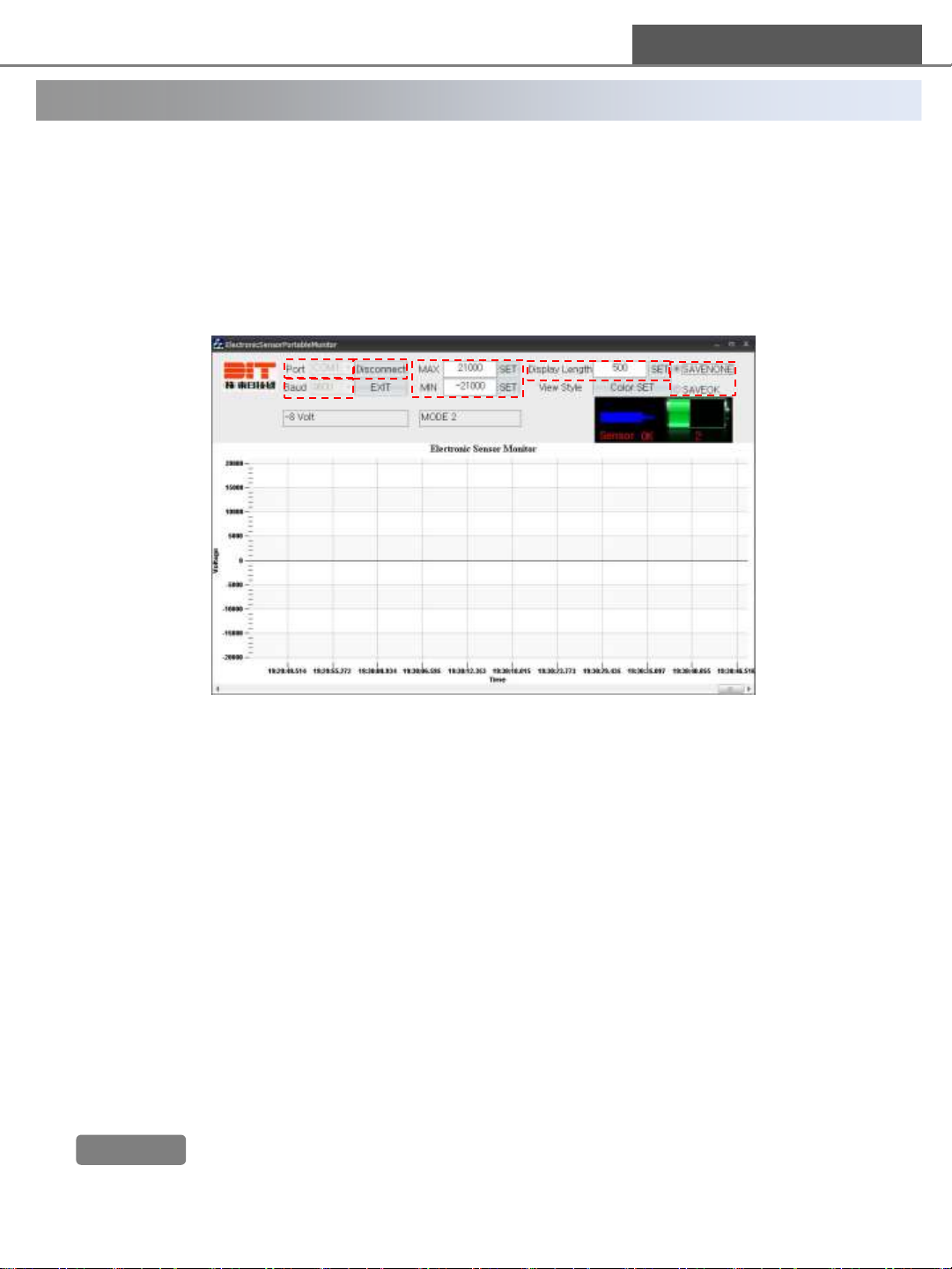
8.2 How to use monitoring program
⑥
③
④
⑤
①
②
1) Specify the same port as the port connecting PC and USB.
2) Set the communication speed. [Fixed value : 9600]
3) Set range of the MAX, MIN voltage value on the Y-axis of the graph.
4) Set the display time on the X-axis of the graph.
5) Select whether to save measured value or not. When selecting save option, the graph
output is not available.
※ The measured value and time is saved continuously in excel file format.
6) After completing the settings, click “connect” button. Then the program starts.
8.3 Case of disconnecting to monitoring program
1) Check the status of USB cable connecting ARS-H002ZA and PC.
2) Check that the port number of USB driver is same as the port number of software.
3) Check to set 9600 baud on monitoring program settings.
4) Check to set 9600 baud on PC port settings.
5) Make sure if the measured value is over the range of the graph(Y: voltage/ X: time)
6) If problem is not solved, contact to the manufacturer or sales agents.
Warning!!
Monitoring program is provided for free. DIT dose not have any responsibility for
damage by user, and customizing this program is not allowed.
15
Page 16

DONG IL TECHNOLOGY LTD
9. Attention
ARS-H002ZA is a portable electrostatic voltmeter, which includes susceptible parts.
Please read carefully the attention below before use.
1) After Reading the instruction manual, use the product according to instruction manual.
2) Make sure to keep the product away from water/oil/solvent/power/etc.
3) Do not use the product in place with corrosive gas such as acid/alkali/etc.
4) Do not give strong impact or vibration to the product. Sensor could be damaged.
5) Make sure to avoid a loaded heavy weight on the LCD panel.
6) Do not use the product in place with strong electromagnetic noise. It may cause
malfunction of integral micro-chip.
7) Make sure to ground the product with a provided earthed cable before use.
8) The Sensing hole part should be avoided condensation.
9) Make sure that the sensing hole is not polluted by water and dust.
10) Do not touch or put sharp objects to the sensing hole.
11) When measuring ion balance, do not face the sensing hole to the object without the
sensing plate.
12) Do not press buttons on main body with excessive force.
13) Keep the sensing plate at a humidity under 60%RH because of its high insulation.
[recommended to use desiccator or plastic bag and desiccant]
14) The sensing plate should maintain its insulation. Otherwise, the measured value is not
guaranteed. Please check the degree of insulation regularly as below.
<How to check the degree of insulation for the sensing plate>
① After charging 100V to the sensing plate, check the decreasing speed. It means that the
insulation resistance is lower as much as the decreasing speed is faster.
② Measure the insulation resistance on the bridge of under the sensing plate. The insulation
resistance should be over 10TΩ (10¹³Ω).
15) Do not break or assembly the product. It may cause malfunction of the product.
Also it is subject to restriction for exchanging or repairing the products.
16
Page 17
10. Trouble shooting
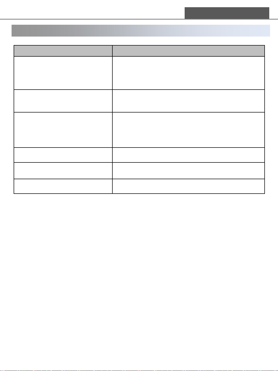
Problems Check points
Power is not supplied
DONG IL TECHNOLOGY LTD
1) Check the battery connection
2) Check the battery charge status
3) If there is no problems above, contact to
manufacturer or sales agents.
Unusual value on DISPLAY
Error is bigger than real electrostatic
value
LED light is OFF 1) Contact to manufacturer or sales agents
Burning smell during operation
ETC. 1) Contact to manufacturer or sales agents
1) Check that ground cable is connected properly
2) Check the settings for measurement mode
1) Check the measurement distance [25mm(±0.5mm)]
2) Check the any other object affecting its performance.
3) If there is no problems above, contact to
manufacturer or sales agents.
1) Remove the battery and contact to manufacturer or
sales agents
※ If you cannot solve the problem with the above solution or if you have other problems
not described above, please call manufacturer or leave a message on our website.
☞ DIT Quality Assurance Team TEL) +82-31-299-5464
17
Page 18
DONG IL TECHNOLOGY LTD
Technology Market Solution
DIT Technology Application Experts are focused on delivering solutions for the
Semiconductor, Electronic Assembly, Photovoltaic, Flat Panel Display, Disk Drive,
Cleanroom. You can be sure of receiving maximum performance and reliability.
We provide cost effective, innovative products best suited to your application
needs.
Warranty
We, Dong Il Technology Ltd. Manufactured this product under a strict quality
control system and warrants it for1 year of period from the shipment date
However, we don’t have any responsibility for
1) Any damage if the product is used in a way different from that is explained in
this
manual or remade by users arbitrarily.
2) Any damage led by improper usage. We recommend the installation
circumstances
in this manual, but that is just a recommendation and users are responsible for
understanding the product’s specification and judgment of suitability of usage.
3) Direct or indirect damage led by the product malfunction.
28, Namyang-ro 930beon-gil, Hwaseong-si, Gyeonggi-do, Korea
Tel 031-299-5453 Fax 031-357-2610
 Loading...