

Page 1
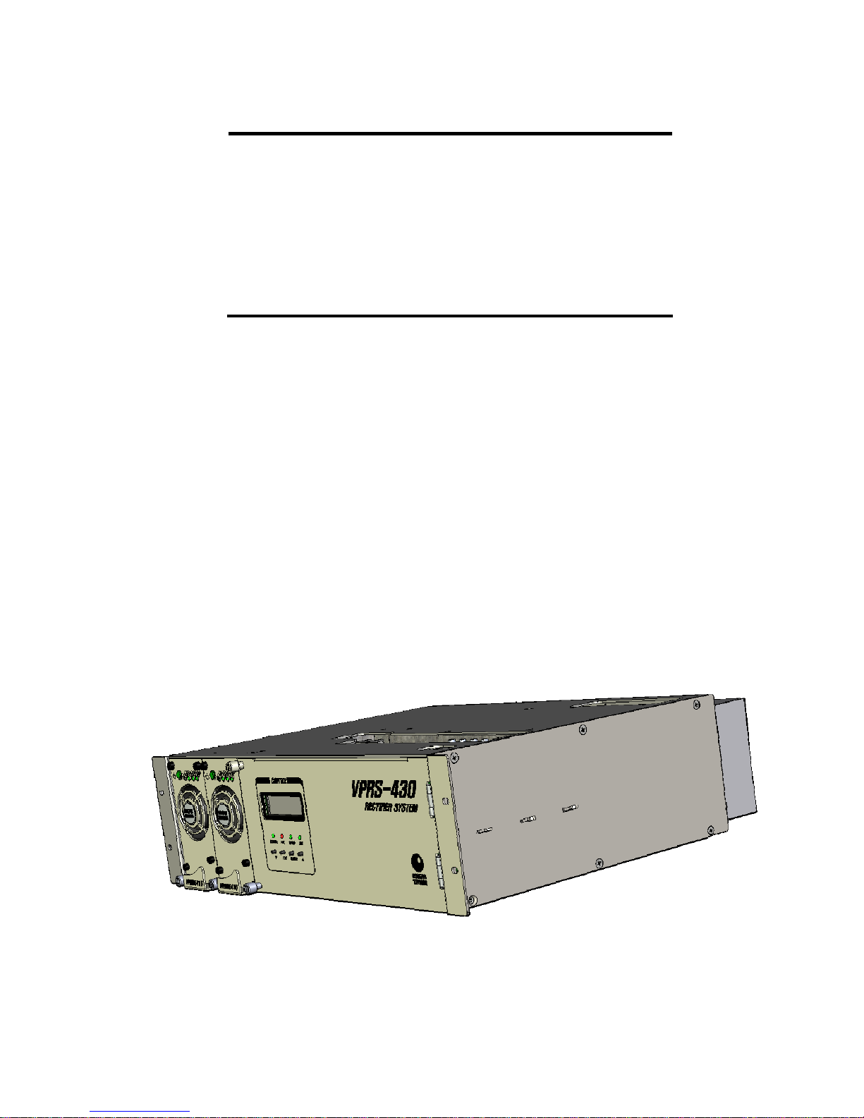
VPRS-430
POWER SUPPLY SYSTEM
OPERATION MANUAL
220V AC 1Phase Input
-54.5VDC Output
30Amps per Shelf
15Amps per Module
Page 2

VPRS-430 OPERATION MANUAL
Issue : 2009.03
ED : 1
- CONTENTS -
1. SYSTEM SPECIFICATIONS.....................................................................................................10
1.1 ELECTRIC CHARACTERISTICS ...............................................................................................10
1.1.1 Input Characteristics ...................................................................................................10
1.1.2 Output Characteristics................................................................................................10
1.2 SAFETY SPECIFICATIONS ......................................................................................................11
1.2.1 Electro Magnetic Interference (EMI).........................................................................11
1.2.2 Surge Voltage of Power Cable..................................................................................11
1.2.3 Leaked Current............................................................................................................11
1.3 ENVIRONMENTAL CHARACTERISTICS ...................................................................................11
1.3.1 Operating Temperature & Humidity..........................................................................11
1.3.2
1.4 PHYSICAL SPECIFICATIONS...................................................................................................11
1.4.1 Dimension.....................................................................................................................11
1.4.2 Weight ...........................................................................................................................11
2 RECTIFIER SYSTEM CONFIGURATION..............................................................................12
2.1 CONFIGURATION ....................................................................................................................12
2.2 FRONT VIEW ..........................................................................................................................12
2.3 FUNCTIONS ............................................................................................................................12
2.4 RECTIFIER SYSTEM BLOCK DIAGRAM ..................................................................................14
Storage Temperature & Humidity
..............................................................................11
3 INITIALIZATION & CHECK POINTS.......................................................................................15
3.1 INSTALLATION CHECK LIST ...................................................................................................15
3.2 RECTIFIER MODULE INSERTION & DELETION ......................................................................15
VPRS-430 OPERATION MANUAL 2 /30
Page 3

VPRS-430 OPERATION MANUAL
Issue : 2009.03
ED : 1
3.2.1 Rectifier Module Insertion...........................................................................................16
3.2.2 Rectifier Module Deletion...........................................................................................16
3.3 NORMAL OPERATION.............................................................................................................16
3.4 ABNORMAL ACTIONS/CORRECTIVE MEASURES ..................................................................17
4 RECTIFIER MODULE CONFIGURATION..............................................................................18
4.1 STANDBY/OPERATING SWITCH.............................................................................................18
4.2 POWER ON LED .................................................................................................................18
4.3 STB LED ...............................................................................................................................18
4.4 ALARM LED .........................................................................................................................19
4.5 ADJUSTMENT VR...............................................................................................................19
5 CONTROL PANEL OPERATION .............................................................................................20
5.1 DISPLAY...............................................................................................................................20
5.2 CONTROL PANEL FUNCTIONS...............................................................................................20
5.3 CONTROL PANEL OPERATION...............................................................................................21
6 MANUAL BATTERY DISCONNECT........................................................................................21
7 RECTIFIER SYSTEM OPERATION & STOP OPERATION................................................22
7.1 RECTIFIER SYSTEM OPERATION...........................................................................................22
7.2 RECTIFIER SYSTEM STOPPING (LOCAL) ............................................................................22
7.3 BATTERY TEMPERATURE COMPENSATION (BTC MODE IN TEMP ON) .............................22
7.4 OUTPUT VOLTAGE FL CHAGE MODE SELECT (TEMP OFF)..............................................23
7.5 OUTPUT VOLTAGE EQ CHARGE MODE SELECT (TEMP OFF) ..........................................24
7.6 RECTIFIER MODULE RESTART..............................................................................................24
7.6.1 When Module is Shut Down by Over Voltage.........................................................25
7.6.2 Rectifier Unit Thermal Shut Down.............................................................................25
VPRS-430 OPERATION MANUAL 3 /30
Page 4

VPRS-430 OPERATION MANUAL
Issue : 2009.03
ED : 1
7.7 BATTERY CHARGE CURRENT LIMITATION............................................................................25
7.8 CONTROL PANEL POWER DROP...........................................................................................25
8 CONTROL PANEL SETUP & MEASUREMENT...................................................................25
8.1 CONTROL PANEL SETUP & FUNCTIONS ...............................................................................25
8.1.1 Float voltage setting....................................................................................................26
8.1.2 Equalize voltage setting..............................................................................................26
8.1.3 Output OV alarm setting.............................................................................................26
8.1.4 Output UV alarm setting.............................................................................................26
8.1.5 New password setting.................................................................................................26
8.1.6 Battery charge current limitation setting...................................................................26
8.1.7 Battery charge end current setting............................................................................26
8.1.8 Battery charge start current setting...........................................................................26
8.1.9 Temp ON/OFF setting.................................................................................................26
8.1.10 Battery charge mode setting......................................................................................26
8.1.11 Battery emergency voltage setting............................................................................26
8.1.12 Alarm History Clerar....................................................................................................26
8.1.13 Alarm Sound Setting..................................................................................................26
8.2 CONTROL PANEL MEASUREMENT ........................................................................................26
8.2.1 Input voltage measurement .......................................................................................26
8.2.2 Output voltage/current measurement.......................................................................26
8.2.3 Battery charge/discharge current measurement ....................................................26
8.2.4 Current measurement per unit...................................................................................26
8.2.5 Rectifier system alarm monitoring.............................................................................26
9 RECTIFIER TEST & MAINTENANCE .....................................................................................26
9.1 OVERVIEW..............................................................................................................................26
9.2 PERIODIC INSPECTION ..........................................................................................................27
9.3 ADDING RECTIFIER MODULE ................................................................................................27
10 PROBLEM SOLVING & FAULT FIXING ............................................................................28
10.1 PROBLEM SOLVING ...............................................................................................................29
10.2 REPLACING PARTS ................................................................................................................29
10.3 ORDER OF REPLACEMENT ....................................................................................................29
VPRS-430 OPERATION MANUAL 4 /30
Page 5

VPRS-430 OPERATION MANUAL
Issue : 2009.03
ED : 1
10.3.1 Replacement of Rectifier Module (VPRM5415)......................................................29
10.3.2 FAN Replacement of Rectifier Module.....................................................................29
10.3.3 Replacement of Surge Protector...............................................................................31
11 ACRONYMS.............................................................................................................................31
Safety Tips
For Your Safe Operation…
- Before starting the installation, operation, test and repair work, please read carefully al of
the directions specified in this manual for your safe operation of the system.
- This product has been manufactured under strict quality management. If there are any
potential damages to human life or assets, please contact Dongahelecomm.
- This document deals with safety directions with the following symbols.
VPRS-430 OPERATION MANUAL 5 /30
Page 6
VPRS-430 OPERATION MANUAL
Issue : 2009.03
ED : 1
If you deal with this system without observing this symbol, it may cause an injury or damage
to assets.
If you deal with this system without observing this symbol, it may cause
death or critical injury.
《Check of Contained Materials》
● Make sure that the delivered product is the same one that you
ordered.
● Check first the quantity of the delivered articles as specified in the
enclosed sheet. Thene, make sure that there are any missing parts,
deformation, damage, peeled out paints, unscrews or damage of
cables.
《Directions in Storage》
● Do not put this product package in a place where water or rain
drops, there are any harmful gas or liquids or direct lay of light
reaches.
● Do not store this product under high temperature and humidity
conditions.
VPRS-430 OPERATION MANUAL 6 /30
Page 7

VPRS-430 OPERATION MANUAL
《Directions in Operation》
Injury, Electric Shock, Fire
Issue : 2009.03
ED : 1
● Do not run this system in a place with flammable or corrosive gases,
dewdrops or humidity. (It may cause an electric shock or fire.)
● Do not try to modify this product. (It may cause an electric burn or
fire.)
● Operate this system under the environmental conditions specified in
this manual. Take particular attention to voltage, frequency,
temperature, humidity and vibrations. (Violating the environmental
requirements may cause an electric shock or fire.)
● Before connecting the battery wire, load and gronding wire, pay
attention not to reverse the polarity of them. (Polarity reversal may
cause fire.)
● While the system is on, do not touch the battery wire, load or
grounding wire ports. It may cause an electric shock or short circuit.
● Pay attention not to reverse polarity of signaling cables and detection
cables when connected. (It may cause a fire.)
● Do not leave alien materials such as sheathes of electric wires,
screws and so on inside the product. (It may cause an electric shock
or fire.)
● DC output is connected to the battery before the system starts to be
VPRS-430 OPERATION MANUAL 7 /30
driven. Pay close attention not to cause an electric shock or short
circuit.
● When the rectifier units are added, pay close attention as AC input
voltage is fed to the Connector in the Shelf side. (It may cause an
electric shock.)
● When you take apart or insert a rectifier unit from/to the Shelf, pay
close attention not to have a burn as the part has been heated. (It
may cause an injury.)
● Do not put your finger or other things to the ractifier unit fan. (It may
cause an injury.)
● When you extend units, pay close attention not to arise an accident
of short circuit. (It may cause an electric shock.)
Page 8

VPRS-430 OPERATION MANUAL
Issue : 2009.03
ED : 1
● When cables are connected, battery should be separated from the
rectifier system except one point of the conductor at each cell.
● Start operation after the connections of battery wire, load, and
grounding wire are taken apart from NFB and fuses.
● Connect the battery wire, load and grounding wire while the load side
has been unloaded.
● External transmission signal should be used at 60V or lower of input
voltage and 0.5A or lower of circuit current.
● Before you take apart or insert the RS232C and RS485 ports of the
control module, turn off the control module switch.
● When you take apart or insert the rectifier unit from/to the rectifier
system, turn off the rectifier unit switch.
● Rectifier unit should be inserted and taken apart in line with the guide
rail of the rectifier system.
● Tightly join the unit fixing screws, and then, turn on the input switch
of the rectifier unit.
● As AC input may be fed to turned on system while power is failed,
special care should be paid to check and maintain the AC input.
VPRS-430 OPERATION MANUAL 8 /30
Page 9
《Test & Repair》
Electric Shock, Fire
VPRS-430 OPERATION MANUAL
● Qualified labor should perform test and repair work periodically with
designated methods. (Violating this direction may cause an electric
shock or fire.)
● Only qualified labor with due knowledge and experience should
repair this product. (Violating this direction may cause an electrtic
shock or fire.)
● As AC input and DC voltage are applied, take particular attention
not to have electric shock or short circuit when the system is tested
or repaired.
Issue : 2009.03
ED : 1
《Disposal》
● Even when the system is turned on while commercial power is
failed, AC input may be fed to the system. Take particular attention
to test and repair work of the AC input.
●This product should be disposed under the ordinary industrial
wastes disposition procedure.
VPRS-430 OPERATION MANUAL 9 /30
Page 10

VPRS-430 OPERATION MANUAL
1. System Specifications
1.1 Electric Characteristics
1.1.1 Input Characteristics
1) Rated input voltage : 1Φ 3W 220Vac
2) Input voltage : 90V ~ 280V
3) Input frequency : 45Hz ~ 65Hz
4) Input rush current : 15Apeak or less (per rectifier module)
5) Efficiency : 90% or greater (at 10% ∼ 100% load)
Issue : 2009.03
ED : 1
6) Power factor : 98% or greater (at 10% ∼ 100% load)
1.1.2 Output Characteristics
1) Rated output voltage : -54.5V ±0.545V
2) Operating voltage : -40.0V ∼ -59.0V
3) Output current : max. 10A (15A × 2 Modules:N+1)
4) Output distribution circuit : Refer to Table 1)
Table 1) Output Distribution
NO Output Port Class Cap. Volt. Description
1 L1~2 DC 10A : 2PORT -54.5V
2 L3~4 DC 6A : 2PORT -54.5V
3 BATTERY#1 DC 20A : 1PORT #1 Battery power supply
-48V
4 BATTERY#2 DC 20A : 1PORT
Load voltage supply
#1 ~#2
Load voltage supply
#3 ~#4
#2 Battery power supply
5)Stability of input and load : ±0.5% (± 0.27V) or less
6)Output current limitation : at 105% ∼ 130% (40% during derating)
VPRS-430 OPERATION MANUAL 10 /30
Page 11

VPRS-430 OPERATION MANUAL
7)Output over voltage protection : Suspend rectifier module at 59.0V ∼
60.0V.
8)Battery over discharge protection : Suspend battery at 42.0V ±0.2V.
9)Output Ripple / Noise : 100mV or less at peat point
1.2 Safety Specifications
1.2.1 Electro Magnetic Interference (EMI)
Î FCC PART 15 SUBPART B, CLASS A
- 450kHz≤ f≤ 1.6MHz : 1mV (60dB ㎶) or lower
- 1.6MHz≤ f≤ 30MHz : 3mV (69.5dB ㎶) or lower
1.2.2 Surge Voltage of Power Cable
Issue : 2009.03
ED : 1
Î Voltage → 6kV (1.2 ×50 ㎲), Current → 3kA (8 × 20 ㎲)
1.2.3 Leaked Current
Î 10mA or lower
1.3 Environmental Characteristics
1.3.1 Operating Temperature & Humidity
-10℃ ∼ +55℃, 10% ∼ 95%
1.3.2 Storage Temperature & Humidity
-40℃ ∼ +80℃, 5% ∼ 95%
1.4 Physical Specifications
1.4.1 Dimension
VPRS-430 Rectifier Shelf ⇒ 132.5(H) X 482.6(W) X 396.2(D) ( mm )
VPRM5415 Rectifier Module ⇒ 130(H) X 65(W) X 331(D) ( mm )
1.4.2 Weight
VPRS-430 Shelf ⇒ 11 Kg (w/o 2 rectifier modules)
VPRS-430 OPERATION MANUAL 11 /30
Page 12

VPRS-430 OPERATION MANUAL
Issue : 2009.03
ED : 1
VPRM5415 Rectifier Module ⇒ 2.6 Kg
2 Rectifier System Configuration
2.1 Configuration
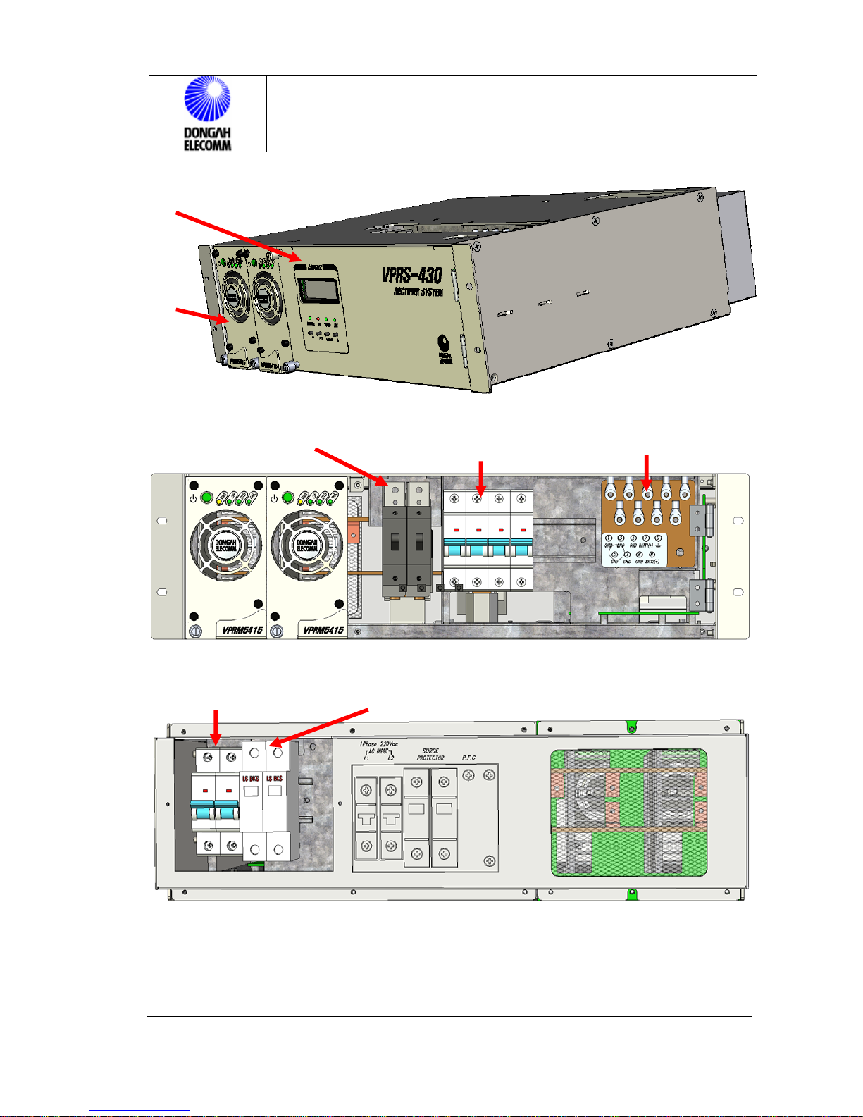
The VPRS-430 rectifier system accommodates max. 2 rectifier units
(VPRM5415). The rectifier system contains control panel (VPRC-30E) and DC
distribution panel. (See Figure 1 Exterior View). The control panel is located at
the front panel of the distribution frame at the rectifier Shelf top. DC distribution
frame contains 4 circuits for load supply and 2 circuit for battery connection.
This rectifier has been designed to charge the battery with positive ground, and
can be used for the system without any battery installed or connected. Rectifier
capacity can easily be built up by adding modules.
2.2 Front View
Figures 1 shows the exterior view of the rectifier.
2.3 Functions
VPRS-430 OPERATION MANUAL 12 /30
Table 2) Rectifier System Functions
Classification
Rectifier Module
[VPRM5415]
Control Panel
[VPRC-30E]
AC distribution
frame
DC distribution
frame
No. of
Modules
2
1
1
1
Receives AC 110V/220VAC, and feeds
DC-48V to load and charges the battery.
Controls up to 2 rectifiers, sends out
alarms.
Receives 1Φ 3W 220Vac.
Distributes output power, and connects
battery.
Function Remark
Page 13
Rectifier
Controler Part
Rectifier
Module Part
VPRS-430 OPERATION MANUAL
Issue : 2009.03
ED : 1
(Front Panel Closed View)
Battery C/B(#1,#2)
AC INPUT C/B9(16A)
Output +27V C/B(L1~L4) Output GND
(Front Panel Open View)
SURGE PROTECTOR
VPRS-430 OPERATION MANUAL 13 /30
(Rear Panel Open View)
Figure 1. Exterior View of VPRS-430
Page 14
VPRS-430 OPERATION MANUAL
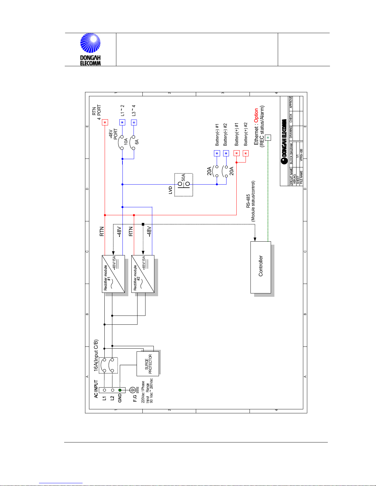
2.4 Rectifier System Block Diagram
Issue : 2009.03
ED : 1
VPRS-430 OPERATION MANUAL 14 /30
Figure 2. VPRS-430 Block Diagram
Page 15

VPRS-430 OPERATION MANUAL
Issue : 2009.03
ED : 1
3 Initialization & Check Points
3.1 Installation Check List
To check installation of the system, take the following procedure:
1) Check if the Shelf has been fixed to the floor.
2) Check if the battery charge temperature compensation probe has been fixed.
3) Check if NFB has been installed in the DC distribution frame.
4) Check if the battery has been correctly connected.
If the battery polarity is reversed, relay will not work when power is fed.
5) Check if the battery C/B is in the ON Position.
6) Check if the Shelf frame ground has been connected to the main ground
busbar.
7) Check if the AC input ground has been connected to the main ground busbar.
8) Check if the I/O cable has been correctly connected.
9) Check if the rectifier modules have been fully inserted.
Once all of the cabling and installation procedures are finished, initialize the system
and carry out the function test in the following order.
1) Check if all of the power switches have been turned off, and check polarity and
cable connection status of batteries using DVM.
2) Check if the input power has been correctly connected and check the input
voltage using DVM.
3) Check if the output cables have been correctly connected, and check polarity.
4) Turn on the AC power switch at the right side of each shelf.
5) Check if the STB LED at the rectifier module is turned to yellow. Then, turn on
the module switch.
6) Check if the POWER LED at the rectifier module is green. Then, turn on the
power switch of the control panel, and check error status on the display window.
3.2 Rectifier Module Insertion & Deletion
VPRS-430 OPERATION MANUAL 15 /30
Page 16

VPRS-430 OPERATION MANUAL
Issue : 2009.03
ED : 1
3.2.1 Rectifier Module Insertion
Rectifier module should be inserted from the left top side of the Shelf. So
insertion should made from left to right and from top to bottom. Turn off the
power switch of each module. Then, insert it until it reaches the end of the Shelf.
Then, tighten the captive screws at the front panel and turn on the power switch.
Keep the switch ON while the rectifier is in operation.
3.2.2 Rectifier Module Deletion
Turn off the power switch of the module. Then, loosen the captive screws on it.
Pull out the module seizing the handle on it.
Before starting the action, wait for about 1 minute until the LED is turned off.
Caution : Turn off power switch when taking apart a module.
3.3 Normal Operation
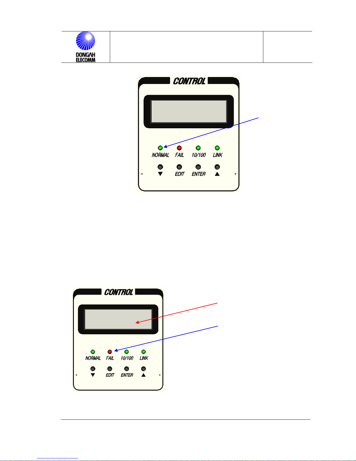
Default setting of the output voltage of this rectifier is BTC-FL MODE. NORMAL
LED and DCV LED at the control panel are turned on. The LCD window provides
information on the rectifier. Using the push button switches [F1(▼), F2(EDIT),
F3(ENT), F4(▲)] at the LCD window, user may query or modify setup values. (See
Figure 3.)
VPRS-430 OPERATION MANUAL 16 /30
Page 17
VPRS-430 OPERATION MANUAL
Issue : 2009.03
ED : 1
Figure 3. Control Panel Front Status Indication (Normal)
3.4 Abnormal Actions/Corrective Measures
If FAIL LED is turned on while the rectifier system is driven, that means the
rectifier system is abnormal in operation. Alarm status is displayed on the LCD
window of the control panel. Check the alarm status and take proper actions.
Error Message Display
Figure 4. Control Panel Front Status Indication (Error)
VPRS-430 OPERATION MANUAL 17 /30
Page 18

VPRS-430 OPERATION MANUAL
Issue : 2009.03
ED : 1
Table 4) Corrective Actions per Alarm
Alarm Corrective Actions
If rectifier unit communication is failed,
⇒
Insert the module to the rectifier system until it reaches the end.
MF
If rectifier unit is off,
⇒ Turn on the power switch of the unit.
DCOV, DCUV
ACUV, ACOV
LVD
B-NFB Check if battery(#1,#2) C/B OFF Position.
OCA
☞
If the listed problem is not solved after the recommended actions are taken,
Check default setting of output voltage.
Check output UV and OV alarm settings.
Measure actual input voltage using DVM.
Check if the battery disconnector switch is in Normal.
Check if the battery has been normally connected.
Check the input voltage, and check if the output is open.
(See How to Operate Control Unit.)
or if other problems occur, contact A/S center.
4 Rectifier Module Configuration
4.1 Standby/Operating Switch
During the operation, the module should be in Operating Mode.
If the switch is in Standby mode, output is not fed.
Caution : Even though the switch is in Standby mode, AC power will be fed to the
module, and the STB LED on the rectifier module will be turned on..
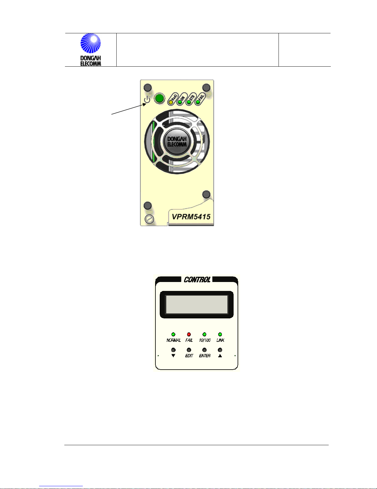
4.2 POWER ON LED
This LED is turned on (green) when the module is normal.
4.3 STB LED
The rectifier module is in standby mode, and does not feed output.
VPRS-430 OPERATION MANUAL 18 /30
Page 19

VPRS-430 OPERATION MANUAL
Issue : 2009.03
ED : 1
Caution: Even though the STB LED is turned on (yellow), AC power will be fed to
the module.
☞While AC power is input, rectifier unit turns on POWER ON LED. When
communication with the control panel is failed or when rectifier module output OC
alarm (OCA) is driven, STB LED (yellow) and POWER ON LED are turned on
simultaneously.
4.4 ALARM LED
In one of the following conditions, ALARM LED(RED) will be turned on:
* When AC power excceds UV/OV limits (UV limit : 90V, OV limit: 290V);
* When the module is shut down due to output OV protection circuit driving;
* When the module is shut down due to internal high temperature protection circuit
driving;
* When the voltage falls below UV limit due to current limit circuit driving;
* When internal fan is failed;
* When the module is shut down due to an external signal (Green, yellow and red
LEDs are blinking.)
* When output is not made due to other problems, or when the voltage falls below
UV limit.
4.5 ADJUSTMENT VR
This function enables to calibrate output voltage of the rectifier module. Turn the
VR to the right to add voltage. Turn it to the left to decrease voltage. Output voltage
has been set to 54.5V. It is recommended not to touch the setting. Load sharing
Voltage Adjustment Resistor
deviation among units may be adjusted.
Power on LED
Standby LED
Alarm LED
VPRS-430 OPERATION MANUAL 19 /30
Page 20
Standby/Operate
Button
VPRS-430 OPERATION MANUAL
Issue : 2009.03
ED : 1
Figure 5. Front View of Rectifier Module
5 Control Panel Operation
5.1 DISPLAY
Figure 6. Control Panel Front View
5.2 Control Panel Functions
See Control Panel Operation Manual.
Table 5) Adjustments Menu Defaults
VPRS-430 OPERATION MANUAL 20 /30
Page 21

VPRS-430 OPERATION MANUAL
Issue : 2009.03
ED : 1
CLASSIFICATION AVAILABLE RANGE DEFAULT
FL Voltage -44.0 ~ -59.0V -54.5V
EQ Voltage -44.0 ~ -59.0V -56.0V
AC INPUT OV/UV ALARM Fixed Value 291Vac / 89Vac
AC INPUT OV/UV S/D Fixed Value 296Vac / 84Vac
DC OUTPUT OV/UV -48.0 ~ -59.0V , -42.0 ~ -52.0V -57.0V / -43.0V
Output Current Limit
Battery Charge Current Limit OFF/ 10A ~ 200A 60A
Battery Charge Current 10A ~ 200A 50A
Battery Charge End Current 2A ~ 100A 5A
Temp Mode ON/OFF ON
Battery Charge Slect
Battery Emergency Voltage -42.0V ~ -48.0V -44.0V
40% (when input voltage is 180V or less)
105% (when input voltage is 190V or higher)
Auto
Manual (FL MODE/EQ MODE)
40% or 105%
Auto
5.3 Control Panel Operation
See Control Panel Operation Manual.
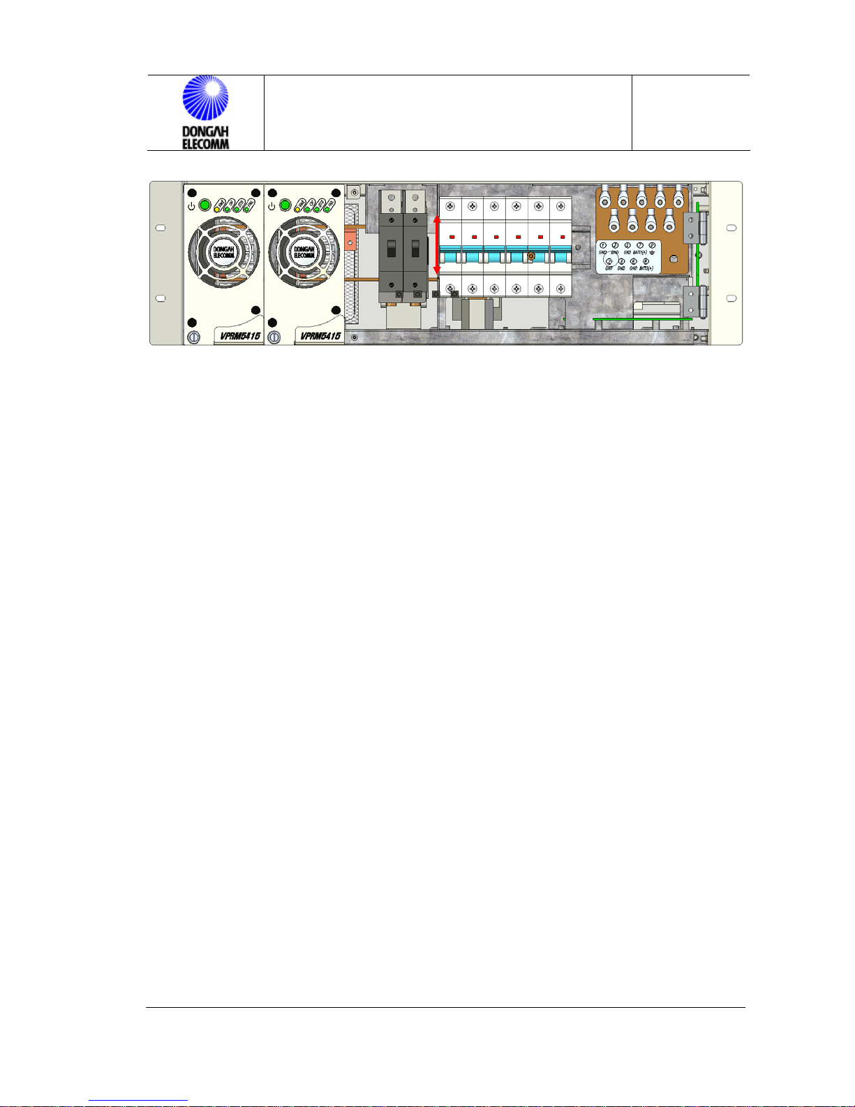
6 Manual Battery Disconnect
Manual BATTERY DISCONNECT switch : C/B(Circuit Breker) type located at the
rear side of the front panel. When the C/B is in ON position, it connects the battery to
the rectifier and the system. (Rectifier is normal and output voltage is 46V or higher.)
Normal operation state.
When it is in OFF position, it separates the battery from the rectifier and the system.
(When battery is repaired or replaced.)
VPRS-430 OPERATION MANUAL 21 /30
Page 22
VPRS-430 OPERATION MANUAL
Figure 7. Battery Disconnect(Front panel Open View)
7 Rectifier System Operation & Stop Operation
7.1 Rectifier System Operation
Issue : 2009.03
ED : 1
① Turn on the AC power switches at the rectifier unit top.
② Yellow LED on each rectifier unit will be turned on.
③ Turn on the switch of each rectifier unit.
④ Turn on the power switch of the control unit.
⑤ Check if the rectifier system name displayed at the LCD of the control unit
matches the actual rectifier Shelf installed.
⑥ Check if the STATUS LED indicates normal.
7.2 Rectifier System Stopping (LOCAL)
① Turn off the switch of each rectifier unit.
② Yellow LED on each rectifier unit is turned on.
③ Turn off the main breaker at the distribution panel.
④ Turn off the power switch of the control unit.
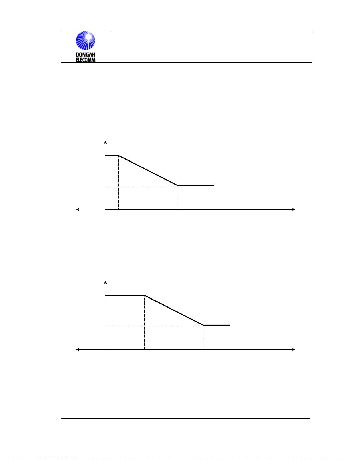
7.3 Battery Temperature Compensation (BTC mode in TEMP ON)
As shown in the Rectifier Installation Manual, install the Battery Temperature
Compensating Probe near the battery Shelf.
Once the temperature probe is connected, and set to BTC mode, the system will
VPRS-430 OPERATION MANUAL 22 /30
Page 23
VPRS-430 OPERATION MANUAL
ED : 1
operate in temperature compensation mode. If the Temp saner probe is taken out,
TEMP OUT is displayed and temperature compensation will not operate. Then, the
system will return to the operator defined mode (FL/EQ).
* FL Charge Mode
Issue : 2009.03
Vout
56.4V
52.8V
-10℃
0℃ 5℃
* EQ Charge Mode
Vout
56.4V
Ac tual Tem perature Corrected Voltage
32℃(90F) or above
25℃(77F)
15℃(59F)
5℃(40F) or below
32℃
Figure 8. BTC-FL MODE
Ac tu al Tem perature C o rrec te d Vo ltag e
52℃(126F) or above
45℃(113F)
35℃(95F)
25℃(77F) or below
2.20V/Cell
2.24V/Cell
2.30V/Cell
2.35V/Cell
Tem p
2.20V/Cell
2.24V/Cell
2.30V/Cell
2.35V/Cell
52.8V
-10℃
0℃
7.4 Output Voltage FL Chage Mode Select (TEMP OFF)
VPRS-430 OPERATION MANUAL 23 /30
25℃ 52℃
Figure 9. BTC-EQ MODE
Tem p
Page 24

VPRS-430 OPERATION MANUAL
Issue : 2009.03
ED : 1
☞ Default is AUTO FLOAT MODE.
1) Manual – FL
Output voltage is maintained constantly at –54.5V.
2) Auto - FL
Auto-FL mode is maintained while the Auto-EQ Mode condition is not met.
7.5 Output Voltage EQ Charge Mode Select (TEMP OFF)
☞ Do not charge the battery too much in EQ mode. Due to high charge voltage,
battery cell may be over-charged shortening the life of the battery.
1) Manual - EQ
Output voltage is maintained at –56.0V.
2) Auto - EQ (Time, Cycle, etc)
• When the rectifier is initialized, it will operate up to 32 hours at AUTO-EQ
mode automatically. That is because the battery may have been discharged in
the storage process.
• If AUTO-EQ is selected, EQ charge is started, and auto-EQ mode is
maintained until 10 minutes pass after current falls below battery end current
limit.
• EQ state is maintained for up to 32 hours after EQ charge gets started.
• If EQ charge period exceeds 90 days, the mode will automatically be changed
to Auto-EQ mode.
* In TEMP ON mode, the system will operate at BTC-EQ and BTC-FL mode.
Output voltage will change depending on the temperature in the battery
Shelf. (For output voltage depending on temperature change, see 7.4 or
Control Panel Operation Manual.)
7.6 Rectifier Module Restart
VPRS-430 OPERATION MANUAL 24 /30
Page 25

VPRS-430 OPERATION MANUAL
Issue : 2009.03
ED : 1
7.6.1 When Module is Shut Down by Over Voltage
If output voltage is suspended due to OV, and then fully shut down due to
regeneration in 5 minutes, manually set off the switch on the front panel to
standby location, and then set on the switch to ON location.
7.6.2 Rectifier Unit Thermal Shut Down
If internal temperature of the unit hikes, the unit will be shut down by its
protection circuit. To restore the module, push the switch at the rectifier unit front
to OFF and then push the switch again to ON manually.
7.7 Battery Charge Current Limitation
This function enables user to set ON or OFF. Default is OFF. In that case, the
maximum value of charge current equals the output current limit of rectifier, which
means max current limit of the installed rectifier modules. (See Table 5.)
7.8 Control Panel Power Drop
If power of the rectifier system falls below 42.0V due to commercial power failure,
all of the control panel functions will be suspended. However, all of set values will
be maintained.
8 Control Panel Setup & Measurement
8.1 Control Panel Setup & Functions
User may edit the alarm and operating voltage of the control panel using the
FUNCTION keys. If any further information is provided, every value should be set
with default value.
VPRS-430 OPERATION MANUAL 25 /30
Page 26

VPRS-430 OPERATION MANUAL
8.1.1 Float voltage setting
8.1.2 Equalize voltage setting
8.1.3 Output OV alarm setting
8.1.4 Output UV alarm setting
8.1.5 New password setting
8.1.6 Battery charge current limitation setting
8.1.7 Battery charge end current setting
8.1.8 Battery charge start current setting
8.1.9 Temp ON/OFF setting
8.1.10 Battery charge mode setting
8.1.11 Battery emergency voltage setting
8.1.12 Alarm History Clerar
8.1.13 Alarm Sound Setting
Issue : 2009.03
ED : 1
⇒ See Control Panel Operation Manual.
8.2 Control Panel Measurement
Control panel displays various measurements related with the operation of the
rectifier system at the front LCD window and the meter window, and displays alarm
and operation status indications.
8.2.1 Input voltage measurement
8.2.2 Output voltage/current measurement
8.2.3 Battery charge/discharge current measurement
8.2.4 Current measurement per unit
8.2.5 Rectifier system alarm monitoring
⇒
See Control Panel Operation Manual.
9 Rectifier Test & Maintenance
9.1 Overview
VPRS-430 OPERATION MANUAL 26 /30
Page 27

VPRS-430 OPERATION MANUAL
Issue : 2009.03
ED : 1
The purpose of this document is to provide guidelines to test the system, setup
measures to restore the system within a shortest possible time when any fault
occurs to the system. In addition, this manual enables to restore any problem in
the system in a short time to normal state. Enough amounts of spare parts must
be prepared to repair fault units. Even though the fault location and reason are
detected under the guidelines of this Manual, if field repair work is not possible, or
long period of time is needed for repair, the fault units should be replaced with
spare ones reserved. Then, the fault units can be repaired with enough amount of
time.
Note : As this rectifier uses AC voltage, it may cause electric shock. As battery
voltage is fed to the system, safety measures should be taken to repair and
maintain the system. As the battery generate a large amount of DC current,
worker should take off watch, ring or other metallic accessories.
9.2 Periodic Inspection
To guarantee effective operation of the system, periodic inspection is required.
Periodic inspection should be carried out one time per 6 months.
1) Take care not to block the air ventilation holes with dusts or other alien
materials.
2) Check the connection and tightening state of cables.
3) Check if internal temperature of the site is maintained in rated level.
4) Check rectifier operation state and alarm state with naked eye.
5) Check fixing on the floor and water leakage on the installation site for the
rectifier system.
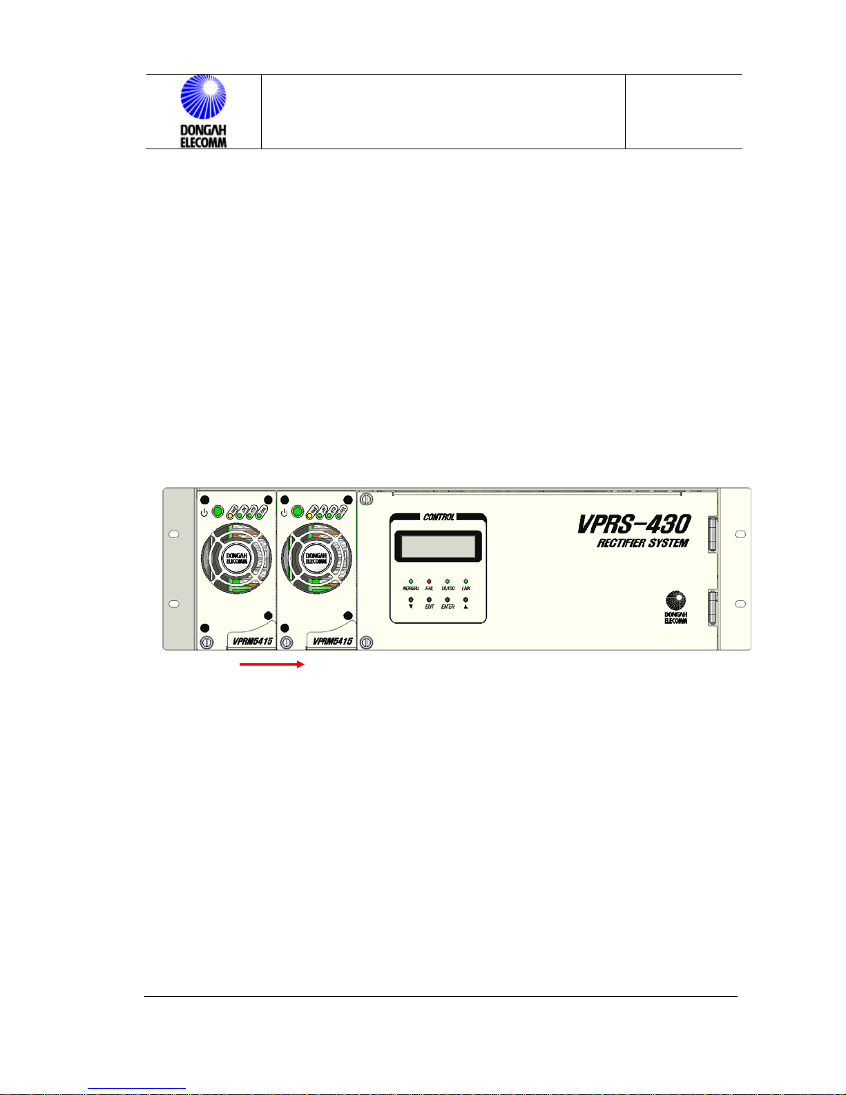
9.3 Adding Rectifier Module
To expand the system capacity, rectifier modules may be inserted to vacant slots.
1) Check if the Standby/Operate switch of the module is set to ‘Standby’.
VPRS-430 OPERATION MANUAL 27 /30
Page 28
VPRS-430 OPERATION MANUAL
Issue : 2009.03
ED : 1
2) Insert a rectifier module to a corresponding slot, and tighten the captive screw
on it.
3) Set Standby/Operate switch of the module to ‘Operate’.
4) Control panel will automatically set current limit of rectifier.
As current limit is set to 50% or 110%, current limitation is made considering
the number of rectifier modules within this range.
5) Verify the voltage and current set on the LCD screen.
* Check load share of each rectifier unit. For details, see Control Panel Operation
Manual.
6) If total current does not increase after a new module is inserted, check if the
module has any problem on it, and check the ID setting of the rectifier module.
7) Check if the rectififer generates any alarm or has any errors on it.
Figure 10. Rectifier Module Insert
10 Problem Solving & Fault Fixing
Repairing or problem fixing of the rectifier should be necessarily carried
out by experienced workers observing safety directions.
* Jobs should be carried out in due order.
* Workers should not wear rings, watches or metallic accessories.
* If non-insulated conductors are used, check using DVM if voltage is fed to
them.
VPRS-430 OPERATION MANUAL 28 /30
Page 29

VPRS-430 OPERATION MANUAL
Issue : 2009.03
ED : 1
- Battery capacity may not be enough to complete the maintenance work of
the system.
- Circuits and boards should be protected from EMI.
10.1 Problem Solving
This rectifier has been designed for users to solve problems easily. The LCD
window of the control panel displays details of faults.
10.2 Replacing Parts
If a fault is suspected on a particular point, circuit board of that point should be
replaced. Replacing or replacement of individual circuits should not be made in
fields. Field replaceable units are limited to fan on a rectifier module, distribution
panel fuse and NFB.
10.3 Order of Replacement
10.3.1 Replacement of Rectifier Module (VPRM5415)
1) When a rectifier module is replaced, alarm will be driven. Turn off the rectifier
module from the control panel, or notify this fact to the person in charge.
2) Set the switch of the rectifier module to ‘STB’.
3) Turn the captive screw of the module counter clockwise. Then, take out the
module from the shelf seizing the handle on it.
4) Check if the switch of the new module is set to ‘STB’. Then, push it to the
end of the shelf along the slide.
5) Turn the captive screw of the module clockwise. Then, fix it to the shelf.
6) Set the switch of the rectifier to ON position.
7) Check if the module operates normally, and if any alarm is driven on it.
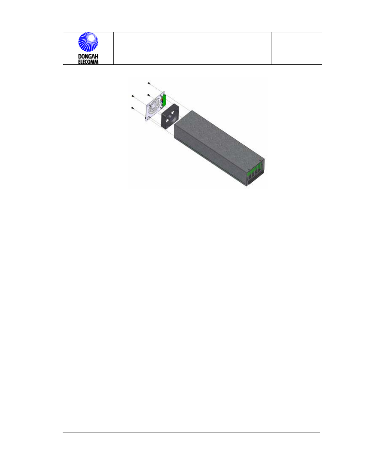
10.3.2 FAN Replacement of Rectifier Module
FAN should be replaced in the following order:
VPRS-430 OPERATION MANUAL 29 /30
Page 30

VPRS-430 OPERATION MANUAL
Issue : 2009.03
1) When a rectifier module is replaced, alarm will be driven. Turn off the
rectifier module from the control panel, or notify this fact to the person
in charge.
2) Set the switch of the rectifier module to ‘STB’.
3) Turn the captive screw of the module counter clockwise. Then, take out
the module fromt the shelf seizing the handle on it.
4) Loosen the 4 screws at the both sides of the rectifier module, and
separate them from the module.
5) Take apart the FAN connector of the separated front panel and power
switch connector from the rectifier module.
6) Loosen the 4 nuts fixing the front panel to the fan.
7) Separate the fan, front panel and fan grill.
8) Replace the fan, and then take the opposite direction from 7) to 4). For
fan assembly, make the arrow mark on the fan facing inner side of the
ED : 1
module. Fan connector cable should face downward, and then
assemble it.
9) Check if the switch of the module to be replace is set to “o” position
(STB state), and then push it to the shelf along the slide until it reaches
the end.
10) Turn the captive screw of the module clockwise to fix it.
11) Operate the module pushing down the switch.
12) Check if the module operates normally, and if there are any alarms on
it.
VPRS-430 OPERATION MANUAL 30 /30
Page 31
VPRS-430 OPERATION MANUAL
Figure 11. Rectifier Module FAN Replacement
10.3.3 Replacement of Surge Protector
Issue : 2009.03
ED : 1
① Get rid of the rear cover from the rectifier system rear.
② Pull out with a hand the part to be replaced from the SURGE PROTECTOR
at the rear.
③ Insert the new part in the opposite order.
Caution : As power is directly applied to the surge protector while input
power is fed, particular care must be paid.
11 Acronyms
GSM : Global Standard [System] for Mobile
NFB : No Fuse Breaker
C/B : Circuit Breaker
S/W : Switch
RMS : Root Mean Square
LVD : LOW VOLTAGE DISCONNECT
VPRS-430 OPERATION MANUAL 31 /30
Page 32

VPRS-430 OPERATION MANUAL
Issue : 2009.03
ED : 1
VPRS-430 OPERATION MANUAL 32 /30
Page 33

VPRS-430 OPERATION MANUAL
ED : 1
Issue : 2009.03
VPRS-430 RECTIFIER
OPERATION MANUAL
©2009 Dongahelecomm Corp.
All rights reserved
Information in this document is proprietary to dongahelecomm
No information contained here may be copied, translated,
transcribed or duplicated by any form without the prior written
consent of Dongahelecomm.
http://www. Dongahelecomm.co.kr
VPRS-430 OPERATION MANUAL 33 /30
 Loading...