

Page 1

208VAC 3Phase Input
-48VDC Output
1400Amps per Rack
200Amps per Module,
60Port per Rack
CPRS-1400,1400DD
INSTALLATION MANUAL
Page 2

CPRS-1400,1400D INSTALLATION MANUAL
Issue : 2004.07
ED : 0
CPRS-1400,1400D INSTALLATION MANUAL 2 /47
- CONTENTS -
1. System Specifications 8
1.1 Electric Characteristics...................................... 8
1.1.1 Input Characteristics........................................ 8
1.1.2 Output Characteristics ...................................... 8
1.2 Safety Specifications ....................................... 9
1.2.1 Electro Magnetic Interference (EMI) .......................... 9
1.2.2 Surge Voltage of Power Cable ............................... 9
1.2.3 Leaked Current ............................................ 9
1.3 Environmental Characteristics ............................... 9
1.3.1 Operating Temperature & Humidity ........................... 9
1.3.2 Storage Temperature & Humidity............................. 9
1.4 Physical Specifications...................................... 9
1.4.1 Dimension ................................................ 9
1.4.2 Weight.................................................... 10
2 Package 10
2.1 Packing State.............................................. 10
2.2 Transportation ............................................. 10
2.3 Unpacking ................................................ 10
2.3.1 Tools ..................................................... 10
3 Installation & Cabling 12
3.1
Exterior View of Rectifier System ............................. 12
3.1.1 Front View ................................................ 14
3.2 Preparation for Rack Installation ............................. 16
3.2.1 Rack Connection........................................... 16
3.2.2 Fixing Anchor.............................................. 17
3.3 Cabling ................................................... 18
3.3.1 Chassis Ground............................................ 18
3.3.2 GND Connection ........................................... 19
3.3.3 Surge Observer Ground..................................... 20
3.3.4 AC Input Connection ....................................... 20
3.3.5 BATTERY LVD Switch ...................................... 22
3.3.6 Installation of BATT Monitoring Module ....................... 22
3.3.7 BATT Cell Check Sensor Connection ......................... 23
3.3.8 Temperature Sensor Connection ............................. 25
3.3.9 Current Sensor per Battery Bank ............................. 25
3.3.10 Comm Cable Connection between Batt Cell Check Module &
Control Panel ......................................................... 25
3.3.11 Comm Cable and Alarm Cable Connection in Control Panel ..... 26
3.3.12 DC Output Connection ...................................... 32
3.3.13 Battery Cable Connection & Fuse Location .................... 34
3.3.14 BAT FUSE ALARM......................................... 36
Page 3

CPRS-1400,1400D INSTALLATION MANUAL
Issue : 2004.07
ED : 0
CPRS-1400,1400D INSTALLATION MANUAL 3 /47
3.4 Installation of Output NFB ................................... 37
3.5 Check Settings ............................................ 39
3.5.1 Rectifier Module ID Setting .................................. 39
4 Initialization & Check Points 40
4.1 INSTALLATION CHECK LIST ............................... 40
4.2 Rectifier Module Insertion & Deletion ......................... 41
4.2.1 Rectifier Module Installation ................................. 41
4.2.2 Rectifier Module Deletion.................................... 41
4.3 Normal Operation .......................................... 42
4.3.1 Initial Operation Status Check ............................... 42
Note that this manual has been written for both rectifier (CPRS-1400) and
distribution panel (CPRS-1400DD). The descriptions on the distribution panel
are specified separately. All of the other ones are descriptions on rectifier.
Page 4
CPRS-1400,1400D INSTALLATION MANUAL
Issue : 2004.07
ED : 0
CPRS-1400,1400D INSTALLATION MANUAL 4 /47
Safety Tips
For Your Safe Operation…
- Before starting the installation, operation, test and repair work, please read carefully al of
the directions specified in this manual for your safe operation of the system.
- This product has been manufactured under strict quality management. If there are any
potential damages to human life or assets, please contact Dongahelecomm.
- This document deals with safety directions with the following symbols.
《Check of Contained Materials》
●Make sure that the delivered product is the same one that you
ordered.
●Check first the quantity of the delivered articles as specified in the
enclosed sheet. Thene, make sure that there are any missing parts,
deformation, damage, peeled out paints, unscrews or damage of
cables.
《Directions in Storage》
●Do not put this product package in a place where water or rain
drops, there are any harmful gas or liquids or direct lay of light
reaches.
●Do not store this product under high temperature and humidity
conditions.
Page 5
CPRS-1400,1400D INSTALLATION MANUAL
Issue : 2004.07
ED : 0
CPRS-1400,1400D INSTALLATION MANUAL 5 /47
《Directions in Operation》
Injury, Electric Shock, Fire
●Do not run this system in a place with flammable or corrosive gases,
dewdrops or humidity. (It may cause an electric shock or fire.)
●Do not try to modify this product. (It may cause an electric burn or
fire.)
●Operate this system under the environmental conditions specified in
this manual. Take particular attention to voltage, frequency,
temperature, humidity and vibrations. (Violating the environmental
requirements may cause an electric shock or fire.)
●Before connecting the battery wire, load and gronding wire, pay
attention not to reverse the polarity of them. (Polarity reversal may
cause fire.)
●While the system is on, do not touch the battery wire, load or
grounding wire ports. It may cause an electric shock or short circuit.
●Pay attention not to reverse polarity of signaling cables and detection
cables when connected. (It may cause a fire.)
●Do not leave alien materials such as sheathes of electric wires,
screws and so on inside the product. (It may cause an electric shock
or fire.)
●DC output is connected to the battery before the system starts to be
driven. Pay close attention not to cause an electric shock or short
circuit.
●When the rectifier units are added, pay close attention as AC input
voltage is fed to the Connector in the rack side. (It may cause an
electric shock.)
●When you take apart or insert a rectifier unit from/to the rack, pay
close attention not to have a burn as the part has been heated. (It
may cause an injury.)
●Do not put your finger or other things to the ractifier unit fan. (It may
cause an injury.)
●When you extend units, pay close attention not to arise an accident
of short circuit. (It may cause an electric shock.)
Page 6

CPRS-1400,1400D INSTALLATION MANUAL
Issue : 2004.07
ED : 0
CPRS-1400,1400D INSTALLATION MANUAL 6 /47
●When cables are connected, battery should be separated from the
rectifier system except one point of the conductor at each cell.
●Start operation after the connections of battery wire, load, and
grounding wire are taken apart from NFB and fuses.
●Connect the battery wire, load and grounding wire while the load side
has been unloaded.
●External transmission signal should be used at 60V or lower of input
voltage and 0.5A or lower of circuit current.
●Before you take apart or insert the RS232C and RS485 ports of the
control module, turn off the control module switch.
●When you take apart or insert the rectifier unit from/to the rectifier
system, turn off the rectifier unit switch.
●Rectifier unit should be inserted and taken apart in line with the guide
rail of the rectifier system.
●Tightly join the unit fixing screws, and then, turn on the input switch
of the rectifier unit.
●As AC input may be fed to turned on system while power is failed,
special care should be paid to check and maintain the AC input.
Page 7
CPRS-1400,1400D INSTALLATION MANUAL
Issue : 2004.07
ED : 0
CPRS-1400,1400D INSTALLATION MANUAL 7 /47
《Test & Repair》
Electric Shock, Fire
●Qualified labor should perform test and repair work periodically with
designated methods. (Violating this direction may cause an electric
shock or fire.)
●Only qualified labor with due knowledge and experience should
repair this product. (Violating this direction may cause an electrtic
shock or fire.)
●As AC input and DC voltage are applied, take particular attention
not to have electric shock or short circuit when the system is tested
or repaired.
●Even when the system is turned on while commercial power is
failed, AC input may be fed to the system. Take particular attention
to test and repair work of the AC input.
《Disposal》
●This product should be disposed under the ordinary industrial
wastes disposition procedure.
Page 8

CPRS-1400,1400D INSTALLATION MANUAL
Issue : 2004.07
ED : 0
CPRS-1400,1400D INSTALLATION MANUAL 8 /47
1. System Specifications
1.1 Electric Characteristics
1.1.1 Input Characteristics
1) Rated input voltage : 3Φ3W(delta connection) 208V
2) Input voltage : 177V ~ 239V
3) Input frequency : 47Hz ~ 63Hz
4) Input rush current : 100Apeak or less (per rectifier module)
5) Throughput : 88% or greater (at 25% ∼ 100% load)
6) Power factor : 96% or greater (at 25% ∼ 100% load)
1.1.2 Output Characteristics
1) Rated output voltage : -54.5V ±0.2V(at 50% load)
2) Operating voltage : -44.0V ∼ -59.0V
3) Output current : max. 1400A (200A ×7 Modules)
4) Output distribution circuit : 60 ports in an independent rack (CPRS-
1400DD).
Table 1) Output Distribution
NO
OUTPUT
PORT
DC/AC CAPACITY VOLTAGE DETAIL
300Amax L1: Power supply to inverter.
200Amax L2~L5: Power supply to load.
1 L1~L60 DC
100Amax
-48V
L6~L60: Power supply to load.
2 BATT.1 DC
800A×2EA
-48V Power supply to BATT.BANK 1.
3 BATT.2 DC
800A×2EA
-48V Power supply to BATT.BANK 2.
4 BATT.3 DC
800A×2EA
-48V Power supply to BATT.BANK 3.
5 BATT.4 DC
800A×2EA
-48V Power supply to BATT.BANK 4.
6 BATT.5 DC
800A×2EA
-48V Power supply to BATT.BANK 5.
7 BATT.6 DC
800A×2EA
-48V Power supply to BATT.BANK 6.
Page 9

CPRS-1400,1400D INSTALLATION MANUAL
Issue : 2004.07
ED : 0
CPRS-1400,1400D INSTALLATION MANUAL 9 /47
• Battery Fuse : 800A×2EA
5)Stability of input and load : ±1.0%(0.54V)
6)Output current limitation : at 40% ∼ 110%
7)Output over voltage protection : Suspend rectifier module at 59.0V ∼
60V.
8)Battery over discharge protection : Suspend battery at 42.0V ±0.2V.
9)Output Ripple / Noise : - 250mV or less at peat point
1.2 Safety Specifications
1.2.1 Electro Magnetic Interference (EMI)
Î FCC PART 15 SUBPART B, CLASS A
- 450kHz≤f≤1.6MHz : 1mV (60dB ㎶) or lower
- 1.6MHz≤f≤30MHz : 3mV (69.5dB ㎶) or lower
1.2.2 Surge Voltage of Power Cable
Î Voltage →6kV (1.2 ×50 ㎲), Current →3kA (8 × 20 ㎲)
1.2.3 Leaked Current
Î 100mA or lower
1.3 Environmental Characteristics
1.3.1 Operating Temperature & Humidity
-20℃ ∼ +50℃, 10% ∼ 90%
1.3.2 Storage Temperature & Humidity
-40℃ ∼ +80℃, 5% ∼ 95%
1.4 Physical Specifications
1.4.1 Dimension
: 1800(H) X 750(W) X 700(D) ( mm )
Page 10

CPRS-1400,1400D INSTALLATION MANUAL
Issue : 2004.07
ED : 0
CPRS-1400,1400D INSTALLATION MANUAL 10 /47
1.4.2 Weight
CPRS-1400 ⇒ 500 Kg or less (rectifier module : 35 Kg)
CPRS-1400DD ⇒ 280 Kg or less
2 Package
2.1 Packing State
This power supply system is shipped with packages of individual rectifier
modules.
2.2 Transportation
Special care should be paid to handle this power supply system as severe shock
or vibrations may cause damages to the system. Transportation of the system
should be made using a container vehicle. If truck or other vehicles are used,
measures to protect from rains should be provided.
2.3 Unpacking
Unpacking should be carried out at a place near installation place. Then, check
exterior of the package if there are any damages caused in the process of
transportation.
2.3.1 Tools
1) Portable computer equipped with a monitoring program.
2) 4-1/2 Digital voltmeter
3) PLUS(+) screw driver
4) MINUS(-) screw driver
5) (-) screw driver for adjustment
6) (+) screw driver for adjustment
7) Cutters, wire stripers(#10 to #22 AWG)
Page 11
CPRS-1400,1400D INSTALLATION MANUAL
Issue : 2004.07
ED : 0
CPRS-1400,1400D INSTALLATION MANUAL 11 /47
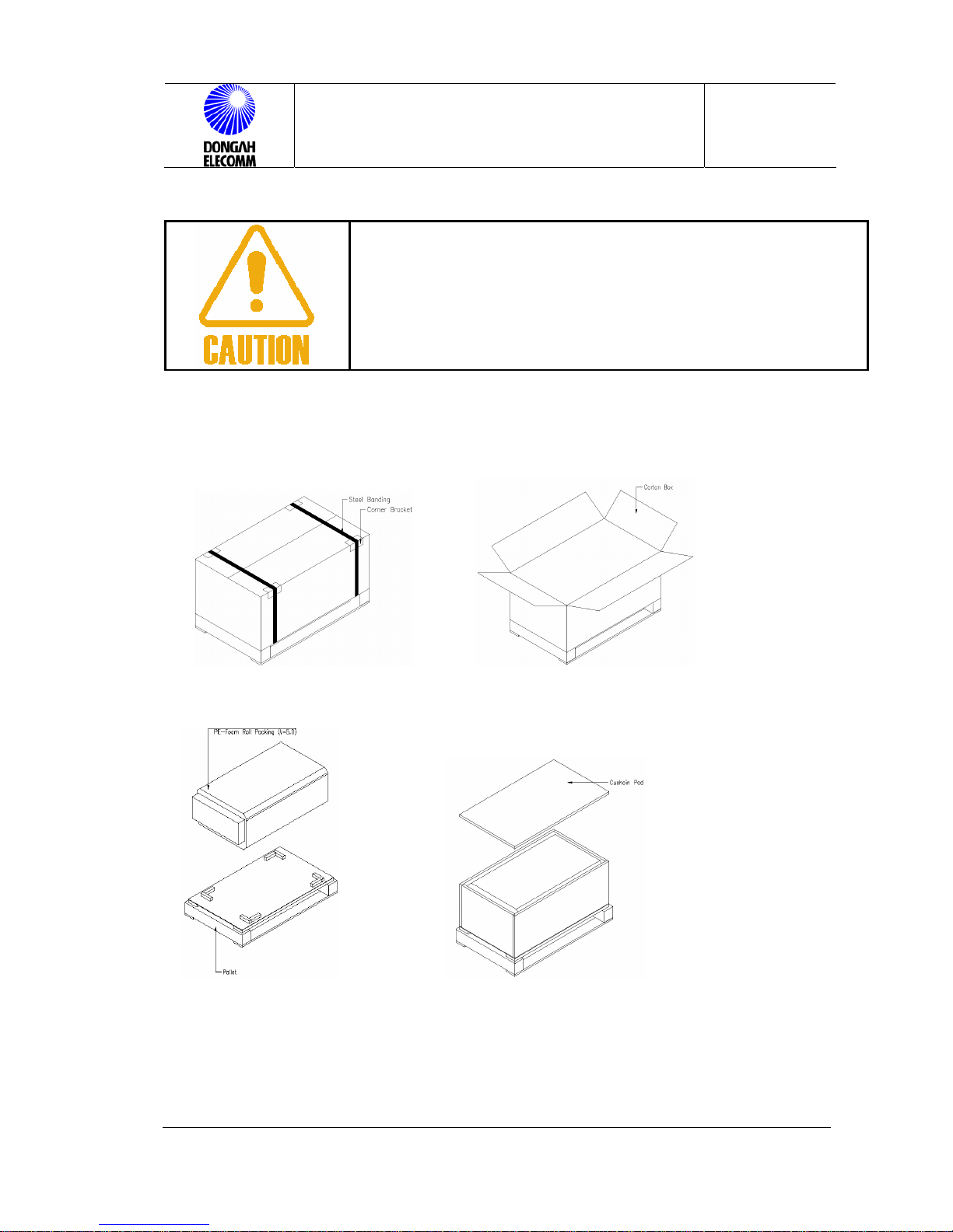
●Before unpacking the system, read carefully the listed directions.
●Pay special attention not to be injured when handling sharp articles
(steel bank, conner bracket etc.)
●Unpack the system in due order so that the system will not be
broken out.
1) Get rid of the steel bands. 3) Take apart the carton box
2) Get rid of the conner brackets
5) Separate the pallet from the enclosure.
4) Take out the cushion pad 6) Get rid of the inner package
Figure 1. Unpacking
Page 12

CPRS-1400,1400D INSTALLATION MANUAL
Issue : 2004.07
ED : 0
CPRS-1400,1400D INSTALLATION MANUAL 12 /47
3 Installation & Cabling
3.1 Exterior View of Rectifier System
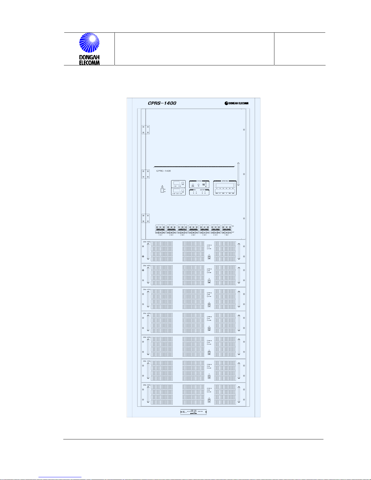
Figure 2. Exterior View of CPRS-1400
Page 13

CPRS-1400,1400D INSTALLATION MANUAL
Issue : 2004.07
ED : 0
CPRS-1400,1400D INSTALLATION MANUAL 13 /47
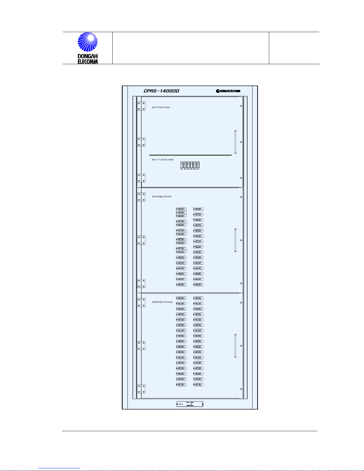
Figure 3. Exterior View of CPRS-1400DD
Page 14
CPRS-1400,1400D INSTALLATION MANUAL
Issue : 2004.07
ED : 0
CPRS-1400,1400D INSTALLATION MANUAL 14 /47
3.1.1 Front View
Figure 4. Front View of CPRS-1400
Page 15
CPRS-1400,1400D INSTALLATION MANUAL
Issue : 2004.07
ED : 0
CPRS-1400,1400D INSTALLATION MANUAL 15 /47
Figure 5. Front View of CPRS-1400D
Page 16

CPRS-1400,1400D INSTALLATION MANUAL
Issue : 2004.07
ED : 0
CPRS-1400,1400D INSTALLATION MANUAL 16 /47
3.2 Preparation for Rack Installation
This rectifier has been designed with 23 inch rack, and fixed with anchor bolts. The
installation place should be clean and dry, and provide minimum of 50cm of space
at the front and rear side of the rack. Front side of the rack should be easy to
ventilate air. All other parts than rectifier modules have been fully installed.
(Options are not the case.)
* Options
NFB to be added for output
Spare battery fuse and fuse holder
3.2.1 Rack Connection
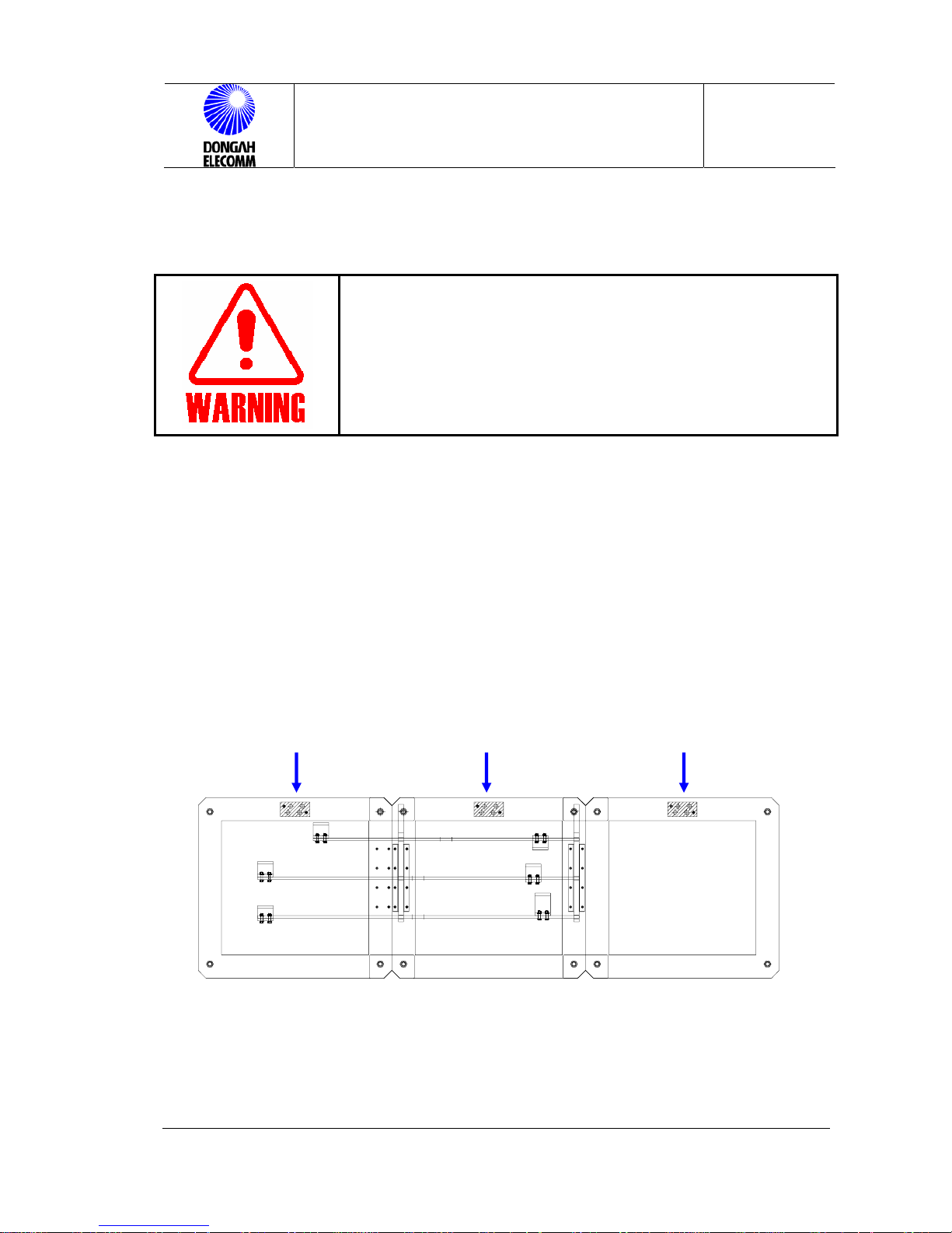
M16 X 14
A
A
CPRS-1400 CPRS-1400DD CPIS-3K/6K
M12 NUT
M12 X 40mm
BUS-BAR
M6 X 20mm
M6 NUT
Figure 6. Fixing Racks Side by Side
Page 17
CPRS-1400,1400D INSTALLATION MANUAL
Issue : 2004.07
ED : 0
CPRS-1400,1400D INSTALLATION MANUAL 17 /47
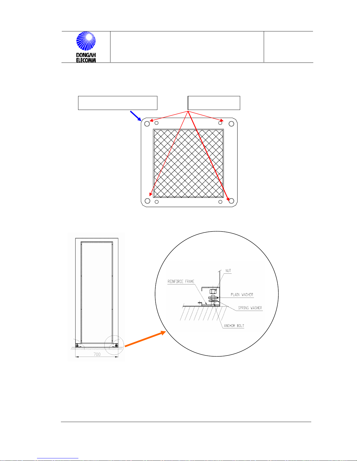
3.2.2 Fixing Anchor
Figure 7. Anchor Fixing Point (Bottom View)
Figure 8 . Anchor Fixing Method
SIDE VIEW
8-M16 TAP Nut Welding ANCHOR Hole
Page 18
CPRS-1400,1400D INSTALLATION MANUAL
Issue : 2004.07
ED : 0
CPRS-1400,1400D INSTALLATION MANUAL 18 /47
3.3 Cabling
●Pay particular attention to keep safety in installing rectifiers.
●Before starting the operation check if AC/DC voltage has been
suspended using DVM.
●Before starting the operation read carefully the following
directions.
●Weight of the chassis is maximum 500kg.
In/output of the CPRS-1400,1400DD rectifier is connected through the terminal
block and bus bar.
AC input and output connection should be made paying attention to input voltage
and polarity orientation of it.
3.3.1 Chassis Ground
The rectifier chassis should be connected using the green wire (14SQ) to the
main ground busbar for safety. The chassis ground should be connected either to
the right side of the input port or to the rack top.
CPRS-1400 CPRS-1400DD CPIS-3K/6K
Figure 9. Chassis GND Connection Point
Page 19

CPRS-1400,1400D INSTALLATION MANUAL
Issue : 2004.07
ED : 0
CPRS-1400,1400D INSTALLATION MANUAL 19 /47
3.3.2 GND Connection
Output GND of the rectifier (RETURN) should be connected to the main ground
busbar over 100SQ cable for safety reason.
BATTERY GND(Return BUSBAR)
BOLT :M12/40mm
LUG : 45mm PITCH 2 HOLE
CPRS-1400 CPRS-1400DD CPIS-3K/6K
GND Bus-bar
-48V Bus-bar
BATT.(-) Bus-bar
Figure 10. GND Connection
Page 20
CPRS-1400,1400D INSTALLATION MANUAL
Issue : 2004.07
ED : 0
CPRS-1400,1400D INSTALLATION MANUAL 20 /47
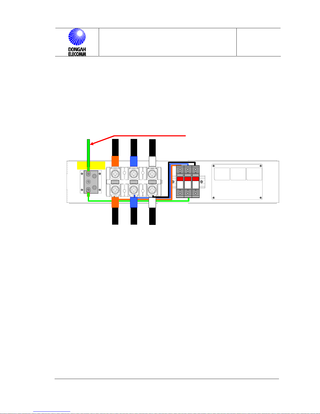
3.3.3 Surge Observer Ground
Surge observer ground should be connected to the main ground busbar using a
green wire (14SQ) for safety.
R S T
R
S
T
SR
T
VAL-
MS
-320
VAL-
MS
-320
VAL-
MS
-320
AC INPUT RATIG
3Q3W, 310A,47~63Hz
AC INPUT WIRE : 150S.Q or greater
Figure 11. Surge Absorbor Ground Connection
3.3.4 AC Input Connection
AC input cable should be separated from DC output as much as possible to
minimize EMI.
.
☞
As AC 3ϕ3W 208V input is used, cable should be connected after voltage
of it is checked.
☞
Thickness of the input cable should be minimum of 150SQ(300 MCM).
☞
Screw should be M12. 1 hole lug should be used.
☞
For cabling see above Figure 11.
SURGE Absorbor Ground
Page 21

CPRS-1400,1400D INSTALLATION MANUAL
Issue : 2004.07
ED : 0
CPRS-1400,1400D INSTALLATION MANUAL 21 /47
Table 2) In/Output Cable Connection & Lugs
Classification Connection Point Wire Size Remark
AC Input AC DIST. ÍÎ INPUT T/B 300 MCM (150SQ) 3ϕ,3W
Chassis Ground RECTIFIER ÍÎ MGB 6 MCM (14SQ) MGB
Ground GND BUSBAR ÍÎ MGB 4/0 MCM(100SQ) MGB
Absorbor Ground Absorbor ÍÎ MGB 6 MCM (14SQ) MGB
BATT #1 cable
DC DIST. ÍÎ
BATT. BANK #1
500MCM(250SQ) X 2P
BATT #2 cable
DC DIST. ÍÎ
BATT. BANK #2
500MCM(250SQ) X 2P
BATT #3 cable
DC DIST. ÍÎ
BATT. BANK
#3
500MCM(250SQ) X 2P
BATT #4 cable
DC DIST. ÍÎ
BATT. BANK
#4
500MCM(250SQ) X 2P
BATT #5 cable
DC DIST. ÍÎ
BATT. BANK
#5
500MCM(250SQ) X 2P
RESER
VED
BATT #6 cable
DC DIST. ÍÎ
BATT. BANK
#6
500MCM(250SQ) X 2P
RESER
VED
Output Cable
(L1 ~ L60)
DC DIST. ÍÎ SYSTEM
300A Î4/0 MCM
200A Î1/0 MCM
100A Î2 MCM
70A Î 4 MCM
50A Î 6 MCM
30A Î 10 MCM
Output
Power
Each lug should be compressed using a proper tool.
Page 22
CPRS-1400,1400D INSTALLATION MANUAL
Issue : 2004.07
ED : 0
CPRS-1400,1400D INSTALLATION MANUAL 22 /47
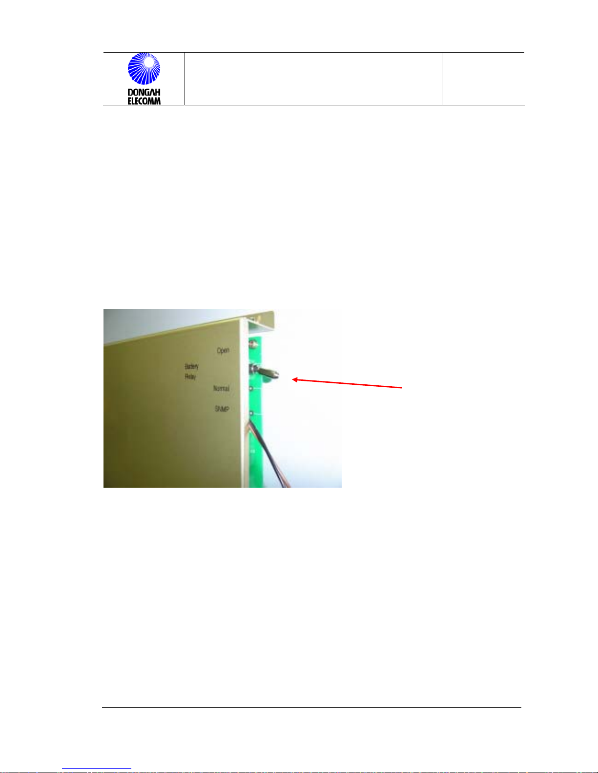
3.3.5 BATTERY LVD Switch
This switch enables to open the LVD(Low Voltage Disconnect). It is used to open
the connection between battery and rectifier by force. For installation or
extension of the battery, pull out the switch to the OPEN side. For normal
operation, the switch should be placed at the NORMAL position to receive
battery backup.
Figure 12. LVD Switch
3.3.6 Installation of BATT Monitoring Module
The BATT monitoring module measures output current, temperature of each
battery bank, and the voltage of battery cell, and informs the result to control
panel. Each battery can accommodate max. 6 banks.
LVD SWTICH
Page 23

CPRS-1400,1400D INSTALLATION MANUAL
Issue : 2004.07
ED : 0
CPRS-1400,1400D INSTALLATION MANUAL 23 /47
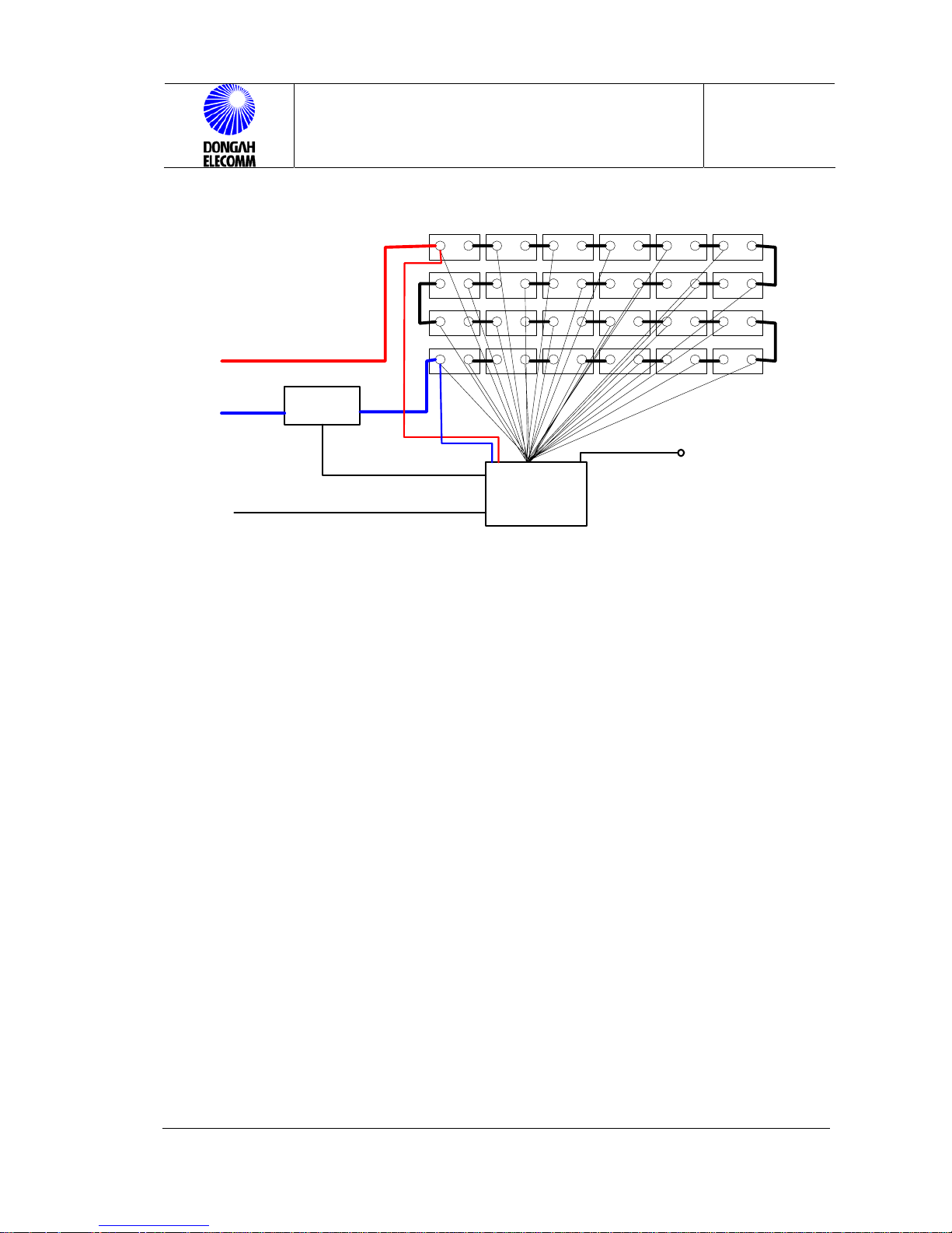
3.3.7 BATT Cell Check Sensor Connection
In order to check any fault on the battery, connect a sensor to each of the battery
cells and measure voltage of each cell. Sensor connection starts with the first (+)
port cell #1, and then continues to cell #24 in parallel. In the same way, connect
the sensor to all cells. (See Fig. 14)
Connect the sensor to the battery. Then, connect the sensor connector to (2)
Batt Cell connector of the BATT monitoring module. (See Fig. 13)
Page 24

CPRS-1400,1400D INSTALLATION MANUAL
Issue : 2004.07
ED : 0
CPRS-1400,1400D INSTALLATION MANUAL 24 /47
(1) : Power Input (2) : Battery cell check (3) : RS 485
(4) : Temp Probe : (5) : Current Sensor
Figure 13. BATT Monitoring Module
(1) (2) (4) (3)
(5)
(1) (2) (3) (4)
(5)
Page 25
CPRS-1400,1400D INSTALLATION MANUAL
Issue : 2004.07
ED : 0
CPRS-1400,1400D INSTALLATION MANUAL 25 /47
+-
1
+- +- +- +-6+-
+-
12
+- +- +- +-
7
+-
+-13+- +- +- +- +-
18
+-
24
+- +- +- +- +-
19
GND
-48V
Hall CT Box
Battey Cell
Check Module
(4) Temp. PROBE
(2)Cell Check
SENSOR
(3)RS 485
(5)Current Sensor
(1)Power In
Figure14. BATTERY CELL CHECK SENSOR CONNECTION
3.3.8 Temperature Sensor Connection
Connect the batt cell check sensor. Then, connect the temperature probe to the
(4) connector in the batt cell check module to measure temperature of the battery
bank. Then, fix it to the middle of the battery bank. (See Fig. 13, 14)
3.3.9 Current Sensor per Battery Bank
To measure current per battery bank, connect the final output (-) busbar of the
battery to current measurement sensor. (See Fig. 14)
3.3.10 Comm Cable Connection between Batt Cell Check Module & Control
Panel
Connect the comm. cable to the CPRC-B of the control panel for RS485
communication.
Page 26
CPRS-1400,1400D INSTALLATION MANUAL
Issue : 2004.07
ED : 0
CPRS-1400,1400D INSTALLATION MANUAL 26 /47
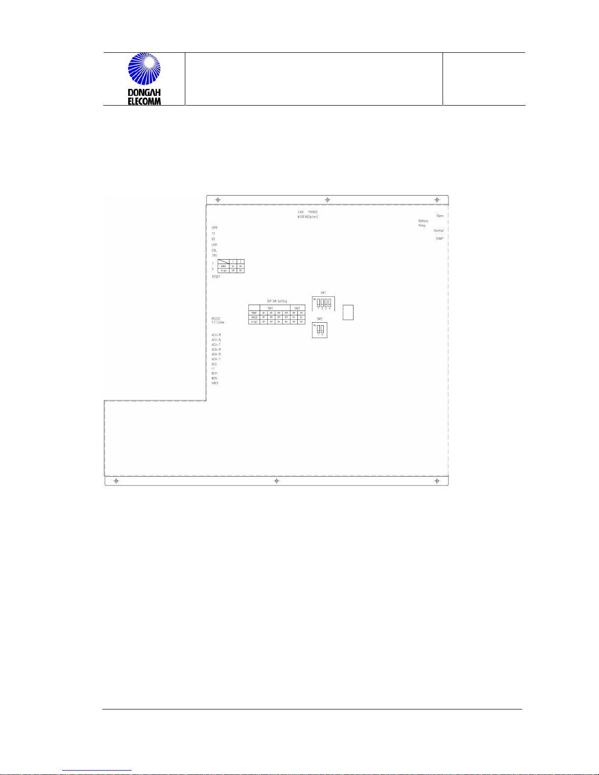
3.3.11 Comm Cable and Alarm Cable Connection in Control Panel
(1) : IPSet DIP SW (2) : IPSet DIP SW (3) : Lan cable
Figure 15 Rear View of Control Panel(With Cover)
1) Remote Controlling LAN Cable Connection & IP Address Setting (When PMS
is Used.)
a. LAN Cable Connection
As shown below, connect the LAN cable to the connector.
(1)
(2)
(3)
Page 27

CPRS-1400,1400D INSTALLATION MANUAL
Issue : 2004.07
ED : 0
CPRS-1400,1400D INSTALLATION MANUAL 27 /47
Figure 16. CPRC-B at the Control Panel Rear(Without Cover)
b. IP Address Setting
① How to Set IP Set DIP Switch in Fig. 15
SW1 SW2
SNMP ON ON OFF OFF OFF OFF
RS232 OFF OFF OFF OFF ON ON
IP SET OFF OFF ON ON OFF OFF
② How to Set IP Set DIP Switch in Fig. 15
1 2
SNMP OFF OFF
IP SET OFF ON
(3) Lan cable
Page 28
CPRS-1400,1400D INSTALLATION MANUAL
Issue : 2004.07
ED : 0
CPRS-1400,1400D INSTALLATION MANUAL 28 /47
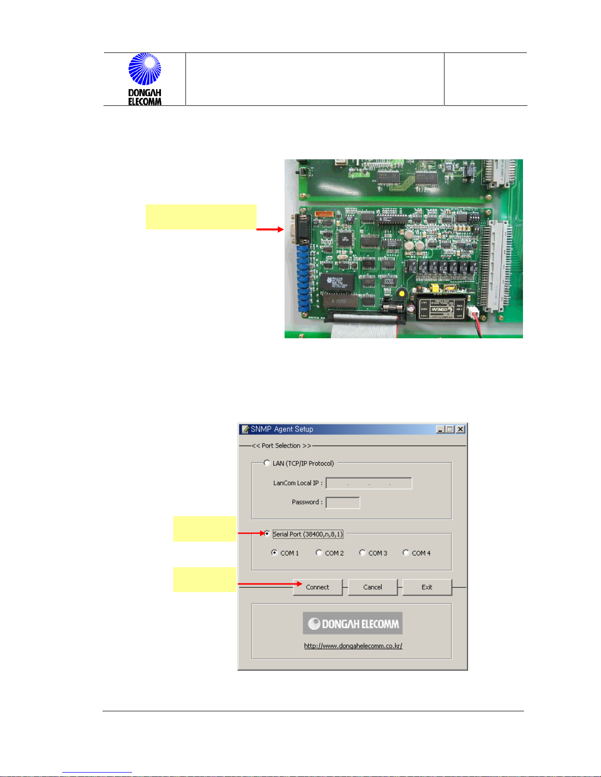
③ IP Setup RS232 Cable Connection
Figure 17. CPRC-M at the Rear of Control Panel (Without Cover)
④ How to Operate the IP Setup Program
Execute Dongah.exe in the furnished program. Then, the following screen
will be displayed.
Figure 18 IP Setup
As shown in above Figure, select a serial port , and click Connect. Then, the
RS232 1:1cable
Select
Click
Page 29

CPRS-1400,1400D INSTALLATION MANUAL
Issue : 2004.07
ED : 0
CPRS-1400,1400D INSTALLATION MANUAL 29 /47
following screen will be displayed, which means that the IP Setup program has
been normally launched.
Figure 18-1 IP Setup
In above Figure, select 1.
Local IP Setup. Then, the
following screen will be
displayed.
Figure 18-2 IP Setup
Key in local IP, gateway and netmask
numbers and click OK. Then, you
escape to X button.
Then, select 2. Server IP Setup to
display the following screen.
1. Local IP setup
2.Server IP setup
Page 30

CPRS-1400,1400D INSTALLATION MANUAL
Issue : 2004.07
ED : 0
CPRS-1400,1400D INSTALLATION MANUAL 30 /47
Figure 18-3 IP Setup
In this screen, up to 4 IPs can be input.
That is, max. 4 servers can operate.
For a server to be used, give a mark to
the box at the left, and keyin
corresponding server IP. Then click OK
to return to X button.
2) Comm Cable Connection in Battery Monitoring Module
.
In the right view, connect the
comm. cable of the Batt monitor
module to one of J20~J25
connectors.
Figure 19. Comm Cable
Connection
3) Inverter Comm Cable Connection
Read out the input voltage, output voltage, battery voltage, output current,
frequency and alarm status of the inverter in operation. In above Figure 19,
connect the inverter comm. cable to J19.
Page 31

CPRS-1400,1400D INSTALLATION MANUAL
Issue : 2004.07
ED : 0
CPRS-1400,1400D INSTALLATION MANUAL 31 /47
4) ALARM Cable Connection
Connect the ALARM cable to the J3~J5 connectors in Figure 20. Alarm status
of the rectifier will be sent out over contacts. Pin assignment is as shown in
Table 3. J3 and 4 are A contact and B contact. J5 is common port. User may
select an alarm port, or use J3/J5 or J4/J5. MOLEX 51067-0500 will be used
for connector. PIN alarm indications are as follows:
RECF Î Rectifier alarm
DCF Î Output voltage alarm (OV,UV)
BF Î Battery alarm
INVF Î Inverter alarm
CTRLF Î Control panel alarm
Figure 20. ALARM Cable Connection
Page 32

CPRS-1400,1400D INSTALLATION MANUAL
Issue : 2004.07
ED : 0
CPRS-1400,1400D INSTALLATION MANUAL 32 /47
<Table 2>. Alarm Pin TABLE (J3,J4,J5)
No J5 J3 J4 ALARM
1 COMMON NORMAL OPEN NORMAL
SHORT
RECF
2 COMMON NORMAL OPEN NORMAL
SHORT
DCF
3 COMMON NORMAL OPEN NORMAL
SHORT
ACF
4 COMMON NORMAL OPEN NORMAL
SHORT
BF
5 COMMON NORMAL OPEN NORMAL
SHORT
INVF
6 COMMON NORMAL OPEN NORMAL
SHORT
CTRLF
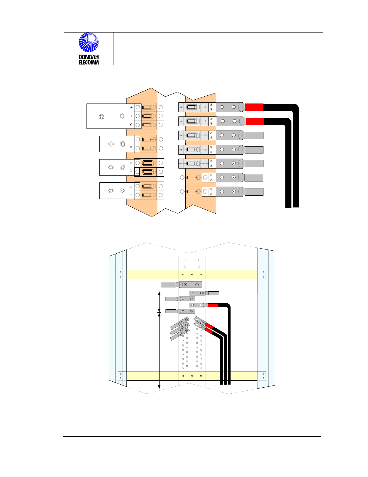
3.3.12 DC Output Connection
DC output connection should be made referring to Table 4), Figures 21 and 22. To
connect the LOAD(-) output cable, open the front door of CPRS-1400DD, unscrew
the distribution panel, and then connect the output cable to corresponding port. To
connect LOAD(+) RETURN(GND), open the rear door as shown in Figure 22,
unscres the panel and connect the output cable to corresponding port.
Page 33
CPRS-1400,1400D INSTALLATION MANUAL
Issue : 2004.07
ED : 0
CPRS-1400,1400D INSTALLATION MANUAL 33 /47
Load 300Amax
Load 200Amax
Load 100Amax
Figure 21. Output Cable Connection (LOAD (-) CONNECTIONS)
Load 300Amax
Load 200Amax
Load 100Amax
Figure 22. Output Cable Connection(
LOAD (+)RETURN(GND)
CONNECTIONS)
Page 34
CPRS-1400,1400D INSTALLATION MANUAL
Issue : 2004.07
ED : 0
CPRS-1400,1400D INSTALLATION MANUAL 34 /47
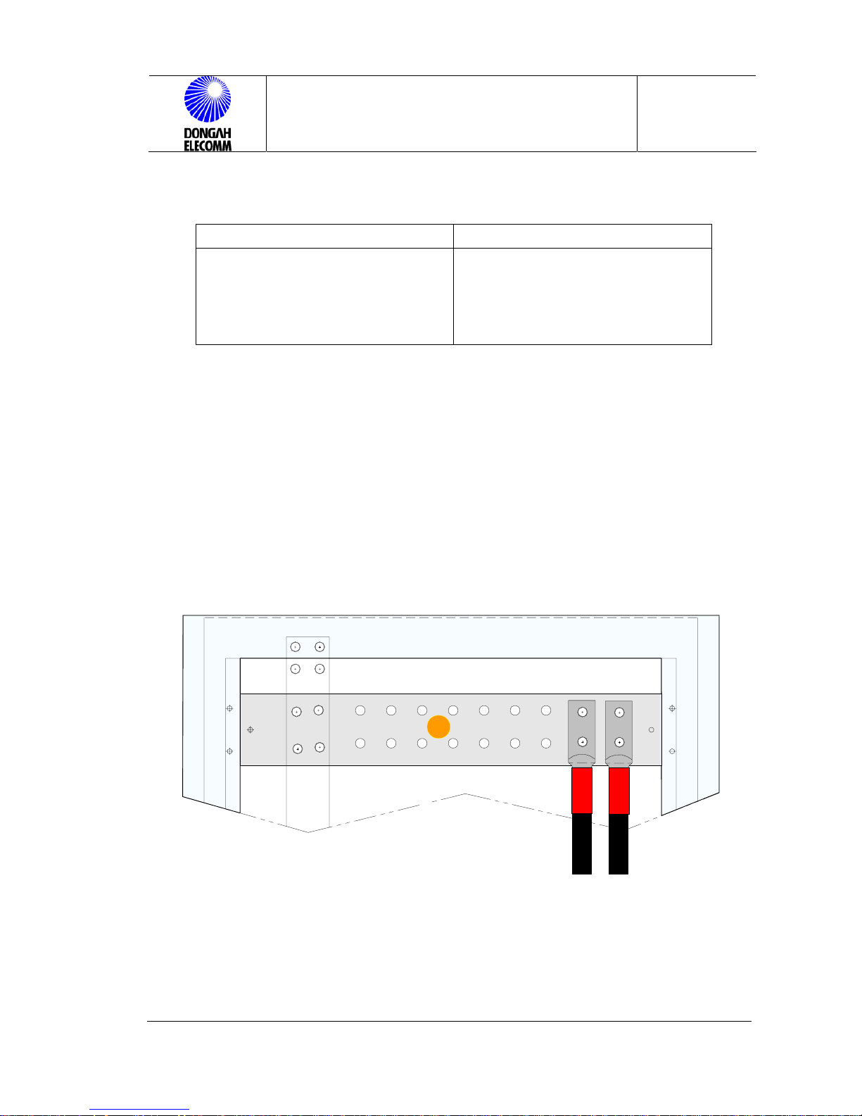
Table 4. Output Cable Connection Bolts & Nuts
LOAD GND (RETURN)
45mm, 2HOLE LUG Î
BOLT : M8, hexa BOLT, 25mm
22mm, 2HOLE LUG Î
OLT : M8. 20mm
45mm, 2HOLE LUG Î
BOLT : M8, hexa BOLT, 25mm
22mm, 2HOLE LUG Î
BOLT : M8. 20mm
3.3.13 Battery Cable Connection & Fuse Location
Caution : Battery should be connected when all other cables have been
connected.
Before connecting the battery, fuse and the alarm fuse should be taken apart. And
set open the LVD OPEN/NORMAL switch of the control panel. Once the cabling is
completed, put the fuse to the original place, and then insert the alarm fuse.
Battery fuse should be rated (800Ax2EA) TPH type.
B+
BATTERY(+) (RETURN BUSBAR)
Page 35

CPRS-1400,1400D INSTALLATION MANUAL
Issue : 2004.07
ED : 0
CPRS-1400,1400D INSTALLATION MANUAL 35 /47
M12 NUT
M12 X 40mm
BATT(-) BUS-BAR
TERMINAL
BATTERY (-) SIDE BUSBAR
BOLT SIZE : M12, 30mm
Figure 23 Battery Connection
Figure 24. Battery Fuse Layout and Installation(CPRS-1400DD)
Page 36

CPRS-1400,1400D INSTALLATION MANUAL
Issue : 2004.07
ED : 0
CPRS-1400,1400D INSTALLATION MANUAL 36 /47
TPHCS FUSE HOLDER
BASE & PULLOUT
TPH TYPE FUSE(800A)
Figure 25. Battery Fuse Type
3.3.14 BAT FUSE ALARM
Fuse for internal battery fuse open alarm (0.5A). When the battery fuse is
opened, visible fuse open alarm will be turned on (HOLE turns to white.) to
indicate the fault.
NOMAL FUSE OPEN
ALARM FUSE
Figure 26. Battery Fuse Alarm
Page 37

CPRS-1400,1400D INSTALLATION MANUAL
Issue : 2004.07
ED : 0
CPRS-1400,1400D INSTALLATION MANUAL 37 /47
3.4 Installation of Output NFB
DC distribution frame of the rectifier accommodates 60 circuits. The rectifier
contains 1 300A port, 4 200A ports and 55 100A ports.
Load 300Amax
Load 200Amax
Load 100Amax
Switch
S/W가 OFF된 상태에서
화살푶 방향으로 밀어 넣는다
Insert to the arrow direction when the switch has been off.
Figure 27 Output NFB Installation
Page 38
CPRS-1400,1400D INSTALLATION MANUAL
Issue : 2004.07
ED : 0
CPRS-1400,1400D INSTALLATION MANUAL 38 /47
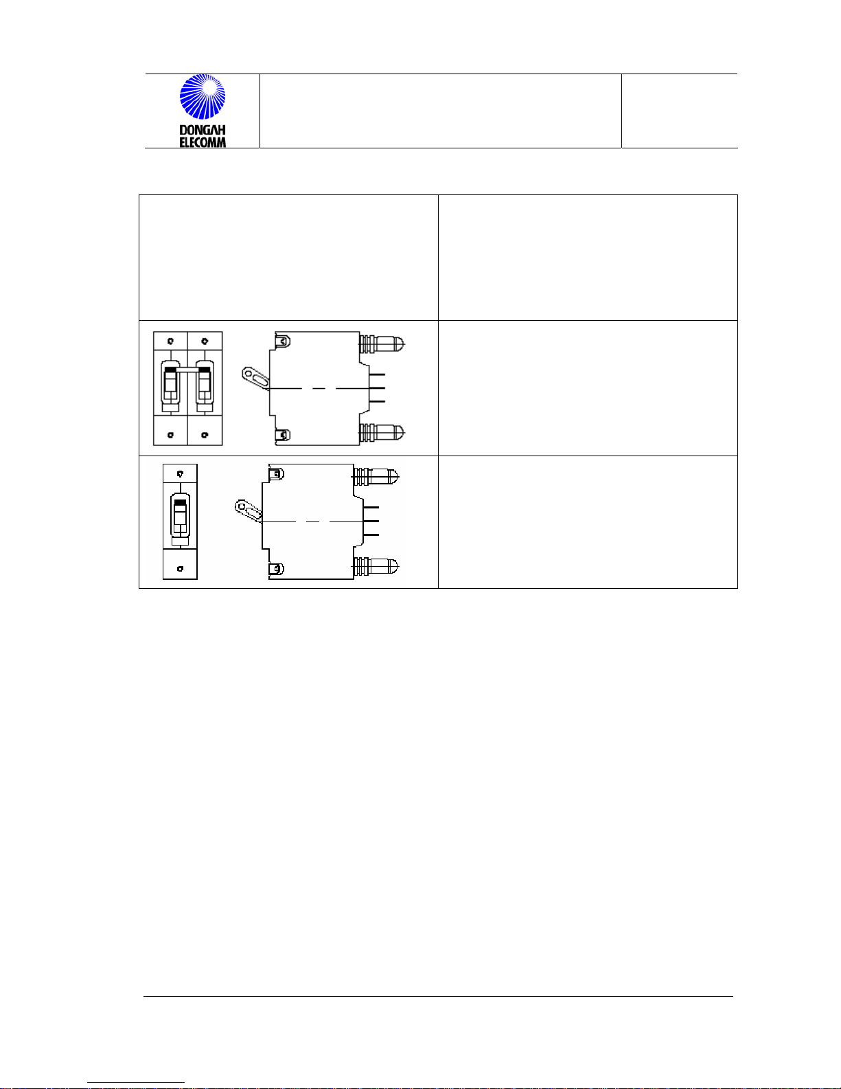
BULLET Nose TYPE
2POLE 150A DC CIRCUIT PROTECTOR
(CARLINGSWITCH)
BULLET Nose TYPE
1POLE 5A ~ 70A DC CIRCUIT
PROTECTOR
(CARLINGSWITCH)
Figure 28. Installation Direction & NFB Type
1
Page 39

CPRS-1400,1400D INSTALLATION MANUAL
Issue : 2004.07
ED : 0
CPRS-1400,1400D INSTALLATION MANUAL 39 /47
3.5 Check Settings
3.5.1 Rectifier Module ID Setting
The order of installing the rectifier module and setting ID are as listed below:
* When shipped, the ID setting DIP switch at the rectifier rear has been set.
* Rectifier module ID should be set from top to bottom from 1 to 7.
Depending on the rectifier moduel installed, check module setup in the LCD of the
control panel.
Î For how to set, refer to 3.2.1, Operation Manual.
ON
1
23
DIP SWITCH
Figure 29. Rectifier Module ID Setup DIP Switch
Page 40

CPRS-1400,1400D INSTALLATION MANUAL
Issue : 2004.07
ED : 0
CPRS-1400,1400D INSTALLATION MANUAL 40 /47
4 Initialization & Check Points
Once all of the cabling and installation procedures are finished, initialize the
system and carry out the function test in the following order. Check carefully if
there are any service failure or alarm in the middle of the test.
1) Check if all of the power switches have been turned off, and check polarity and
cable connection status using DVM. (Check the battery and the LOAD cable.)
2) Check if the input power has been correctly connected using DVM.
3) Check if the output cables have been correctly connected, and check polarity.
4) Turn on the NFB of each rectifier module.
5) Check if the rectifier module LED is all green, and check output voltage.
4.1 INSTALLATION CHECK LIST
To check installation of the system, take the following procedure:
1) Check if the rack has been fixed to the floor.
2) Check if the battery charge temperature compensation probe has been fixed.
3) Check if the RS485 interface of the control panel has been installed and
connected.
4) Check if the SNMP interface of the control panel has been installed and
connected.
5) Check if NFB has been installed in the DC distribution frame.
6) Check if the manual battery LVD switch is in the NORMAL mode.
7) Check if audible alarm switch of the control panel is ON.
8) Check if the rack frame ground has been connected to the main ground
busbar.
9) Check if the AC power ground is connected to the main ground busbar.
10) Check if the I/O cable has been correctly connected.
11) Check if the rectifier modules have been fully inserted.
Page 41
CPRS-1400,1400D INSTALLATION MANUAL
Issue : 2004.07
ED : 0
CPRS-1400,1400D INSTALLATION MANUAL 41 /47
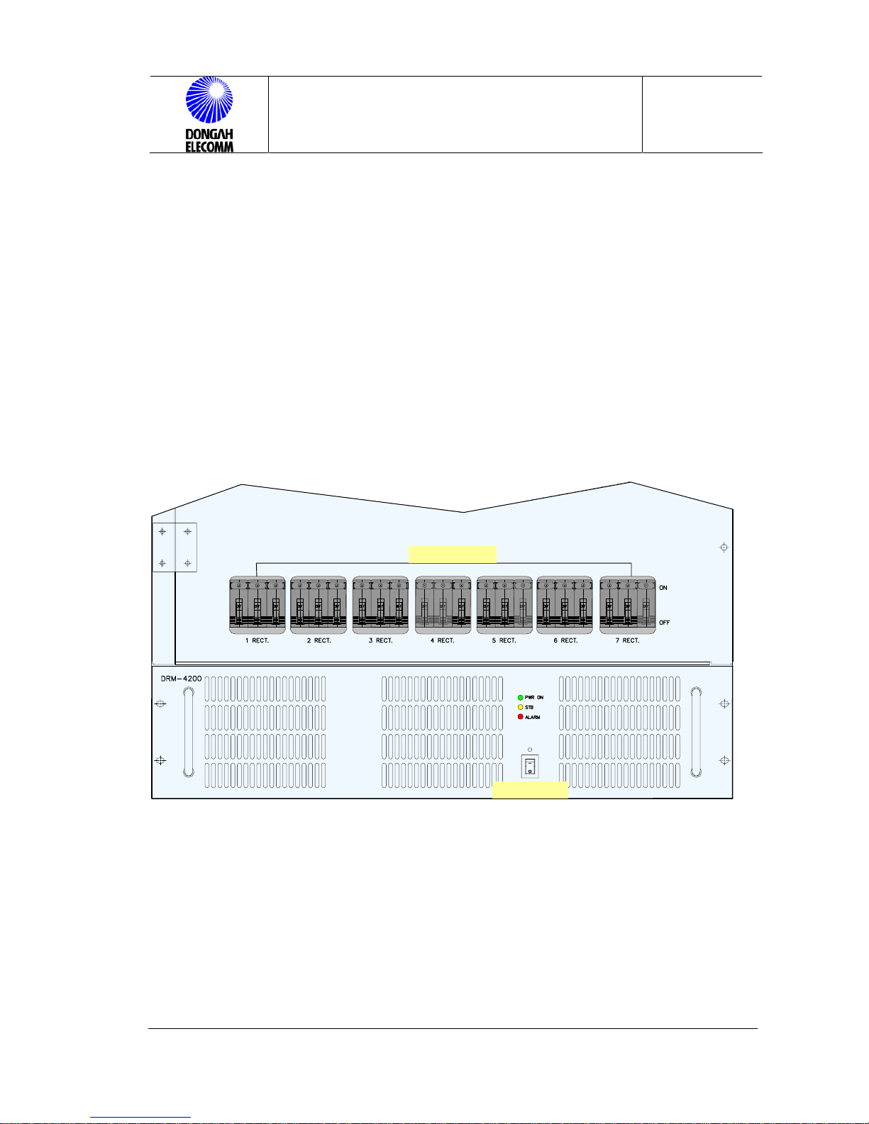
4.2 Rectifier Module Insertion & Deletion
Caution : Before deleting a module make sure that the NFB and switch of each
unit is turned off.
4.2.1 Rectifier Module Installation
Each rectifier module should be inserted to the rack from the top. Then, insert
each module until it reaches the contact. Then, tighten the screen at the panel
front. Turn on the NFB at the top, and turn on the power switch.
MODULE NFB
POWER S/W
Figure 30. Front View
4.2.2 Rectifier Module Deletion
Turn off the NFB and the power switch of the rectifier module. Then, unscrew the
module, and pull it off seizing the handle. Then, wait for 1 minute until the LEDs are
turned off before starting an operation.
Page 42

CPRS-1400,1400D INSTALLATION MANUAL
Issue : 2004.07
ED : 0
CPRS-1400,1400D INSTALLATION MANUAL 42 /47
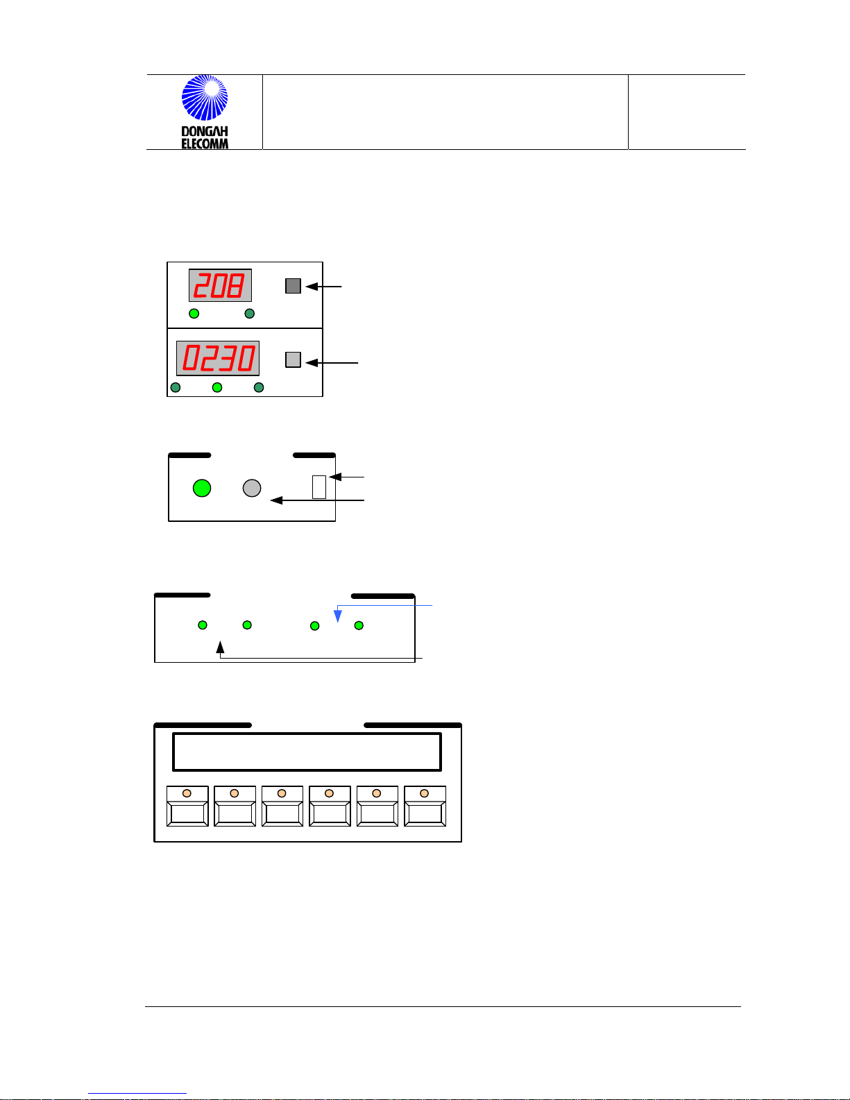
4.3 Normal Operation
Default setting of the rectifier is FLOAT mode. NORMAL LED and AC LED at the
control panel will be turned on. The LCD window shows various information of the
rectifier (See the Figure). User may check change or status of setup using the
PUSH BUTTON switch at the window.
4.3.1 Initial Operation Status Check
1) Rectifier Module(DRM-4200)
Î Check if the ON LED is turned on.
Î Check if STB and ALARM LEDs are turned off.
If the STB LED is ON, communication with the control panel is failed or not
connected. Check the initialization checkpoints again.
Î Check if fan operates normally.
2) Control Panel(CPRC)
Î Check if the status indication LED turns the NORMAL(Green) on.
Î Check if output voltage is correctly displayed on the VOLT METER window.
Î Check if output current is correctly displayed on the AMPERE METER
window. (Depending on load, displayed values may vary. )
Î Check if the REC TX/RX (Green) is blinking on the RS 232 status indicating
LED window.
Î Check if there is no alarm signs on the LCD window, and current status is
correctly displayed on the window.
※ Depending on the number of rectifier modules, max current displayed on the
LCD window may be different. (EX: 3 modulesÎ 3 X 200A X 110% =
660Amax)
See Figure 31.
Page 43
CPRS-1400,1400D INSTALLATION MANUAL
Issue : 2004.07
ED : 0
CPRS-1400,1400D INSTALLATION MANUAL 43 /47
①
Voltage/Current Display
V
A
ACV DCV
ACA LDA BDA
Make choice of input voltage or output voltage
Make choice of currrnt, input currrent,
output currrent, battery currrent.
②
Alarm Display
NORMAL
STATUS
ON
OFF
SOUND
ALARM
FAIL
Make choice of audio alarm switch.
Green LED: NORMAL Red LED : FAIL
③
Comm Status Display
RX
REC
TX
MONITOR
RX
TX
In communication with Rectifier unit
In communication with SNMP
④
LCD Display
Operating display menu
OPERATING
F1 F2 F3 F4 F5 F6
DISPLAY EDIT ENTER UP DOWN ALARM
V 1. 0 Temp : OFF 880Amax
MANUAL - FL MODE 54.5Vadj
3) How to Charge Battery (EQ Charge Start)
Î Initial EQ charge is necessary to compensate the natural discharge in
storage state since the battery was installed.
Î
To set initial EQ charge:
Page 44
CPRS-1400,1400D INSTALLATION MANUAL
Issue : 2004.07
ED : 0
CPRS-1400,1400D INSTALLATION MANUAL 44 /47
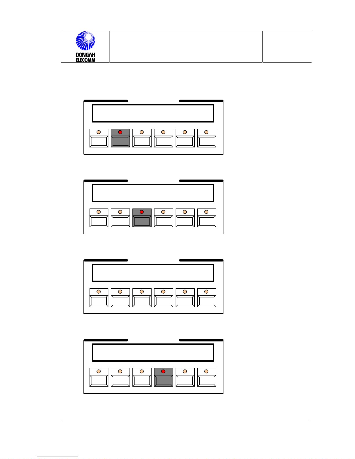
①
Press F2 in the following display:
OPERATING
F1 F2 F3 F4 F5 F6
DISPLAY EDIT ENTER UP DOWN ALARM
V 1. 0 Temp : OFF 880Amax
MANUAL - FL MODE 54.5Vadj
②
Default password is ‘000000’. Press F3.
OPERATING
F1 F2 F3 F4 F5 F6
DISPLAY EDIT ENTER UP DOWN ALARM
E n t e r P a s s N u m b e r ?
< - - : F 1 0 0 0 0 0 0 F 6 : - - >
③
Keep pressing F2 until the following view is displayed:
OPERATING
F1 F2 F3 F4 F5 F6
DISPLAY EDIT ENTER UP DOWN ALARM
B a t t e r y E Q C h a r g i n g
S t a r t ? N O
④
Press F4 to set to ‘YES’.
OPERATING
F1 F2 F3 F4 F5 F6
DISPLAY EDIT ENTER UP DOWN ALARM
B a t t e r y E Q C h a r g i n g
S t a r t ? Y E S
Page 45
CPRS-1400,1400D INSTALLATION MANUAL
Issue : 2004.07
ED : 0
CPRS-1400,1400D INSTALLATION MANUAL 45 /47
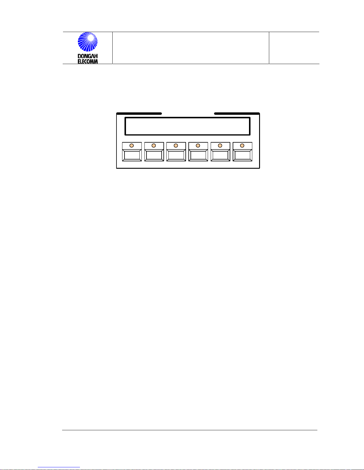
⑤
Press F5 to confirm. Then, the EQ charge (default : 56.0V) will be started.
OPERATING
F1 F2 F3 F4 F5 F6
DISPLAY EDIT ENTER UP DOWN ALARM
V 1. 0 Temp : OFF 880Amax
AUTO - EQ MODE 56.0Vadj
Figure 31.Control Panel LCD Display
Page 46

CPRS-1400,1400D INSTALLATION MANUAL
Issue : 2004.07
ED : 0
CPRS-1400,1400D INSTALLATION MANUAL 46 /47
This page intentionally left blank
Page 47

CPRS-1400,1400D INSTALLATION MANUAL
Issue : 2004.07
ED : 0
CPRS-1400,1400D INSTALLATION MANUAL 47 /47
CPRS-400,800 RECTIFIER
INSTALLATION MANUAL
©2004 Dongahelecomm Corp.
All rights reserved
Information in this document is proprietary to dongahelecomm
No information contained here may be copied, translated,
transcribed or duplicated by any form without the prior written
consent of Dongahelecomm.
http://www. Dongahelecomm.co.kr
 Loading...