

Page 1
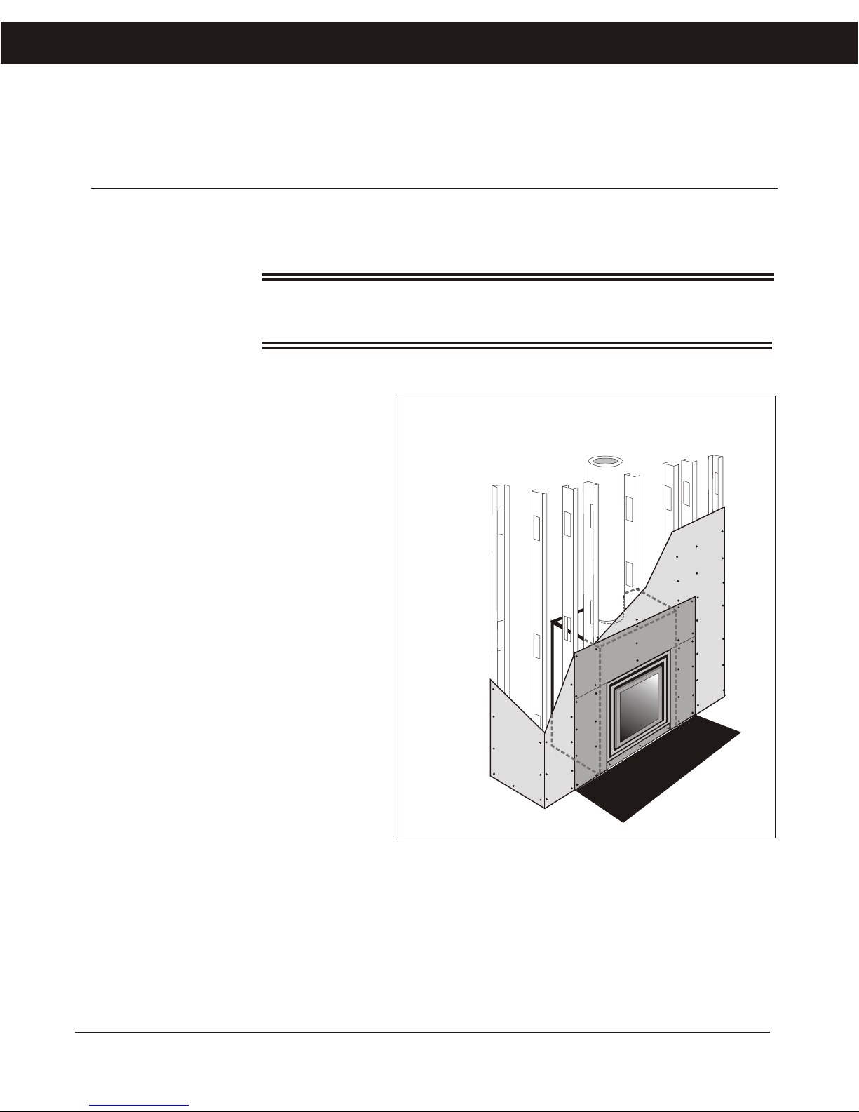
Keep these instructions for future use
Installation, Operation
and Maintenance Manual
LES FOYERS
DON-BAR
FIREPLACES
ZERO CLEARANCE
REV. 2016-01
FIREPLACES (ZC)
Les foyers DON-BAR Fireplaces, inc.
Shop and Showroom: 741, St-Vallier Ouest, Quebec (Quebec) G1N 1E2
Phone: (418) 686-9114 - Fax: (418) 686-9117
Website: www.don-bar.com - Email: [email protected]
Page 2

LES FOYERS
DON-BAR
FIREPLACES
Installation, Operation,
and Maintenance Manual
The manual is divided into 5 parts:
PART 1: Installation ................................................
PART 2: Security, Operation and Maintenance ...
PART 3: Parts List .................................................
PART 4: Chimney Fires ..........................................
PART 5: Warranty ...................................................
This document in its entirety is the intellectual property of Les Foyers Don-Bar inc.
Any unauthorized use will expose its author or authors to legal and financial penalties.
Copyright © 2014 - Les Foyers Don-Bar inc.
THE ZC SERIES FIREPLACES MEET THE REQUIREMENTS OF:
ULC S627 in Canada, UL 1482 in the USA
EPA: Certified EPA Exempt
Page 3
Page 16
Page 22
Page 23
Page 25
REV. 2016-01
Page 1
Page 3

PART 1: INSTALLATION
1. Warnings and cautions 9. Heating ducts installation (optional)
1.1. Modifications
1.2 Installation instructions
1.3 Applicable Codes
1.4 Professional installation
1.5 Before your first fire
1.6 Installation prohibited
2. Typical interior installation
3. Typical exterior installation
4. Before beginning the
installation
4.1 Choosing the best location
4.1.1 Chimney
4.1.2 Chimney minimum height
4.1.3 Minimum clearances from combustible materials
5. Factory-built chimney installation
5.1 Listed parts
5.2 Maximum allowed offsets
5.3 Radiation shield/firestop
5.4 Chimney weight
6. Anchor plate installation
6.1 Fixing the anchor plate
9.1 Heating an upper or lower floor
9.2 Heating a lower floor
9.3 Axial fan installation
9.4 Recommended ducts for heating
9.5 Heating an upper floor
9.6 Danger of overheating
10. Fireplace finishing
10.1 Metallic studs mandatories
10.2 Ventilated frame
10.3 Non combustible cement boards
10.4 Fixing the cement boards against the insulated
case
10.5 Gypsum boards finish
11. Floor protection installation
11.1 Non-combustible floor protection
11.2 Removing the existing resilient flooring
12. Combustible mantel
12.1 Required clearances
13. Anti-smoke flap (optional)
13.1 Anti-smoke flap installation
14. Exterior air intake
14.1 Exterior air intake(optional)
7. Insert installation
7.1 Raised base
7.2 Insert positioning
7.3 Stainless steel liner installation
8. Factory-built chimney installation
8.1 Securing the anchor plate
8.2 Chimney lengths installation
8.3 Minimum chimney height above the roof
8.4 Flashing water tightness
8.5 Roof braces
8.6 Chimney top
REV. 2016-01
Page 2
Page 4
PART 1: INSTALLATION
1. Warnings and Cautions
DO NOT OVERIFRE THE UNIT.
DO NOT OBSTRUCT SPACE UNDER
FIREPLACE. CLEARANCES FROM
COMBUSTIBLE MATERIALS CANNOT BE
REDUCED.
BURN WOOD ONLY. DO NOT USE OTHER
FUELS.
DO NOT INSTALL IN A MOBILE HOME.
DO NOT CONNECT THIS UNIT TO A CHIMNEY
FLUE SERVING ANOTHER APPLIANCE.
ALWAYS PROVIDE A SOURCE OF FRESH AIR
IN THE ROOM. AN EXTERIOR FRESH AIR
SOURCE MAY BE REQUIRED.
DO NOT ALTER THE AIR CONTROL.
IINSPECT AND CLEAN CHIMNEY
FREQUENTLY. UNDER CERTAIN
CONDITIONS OF USE, CREOSOTE BUILDUP
MAY OCCUR RAPIDLY.
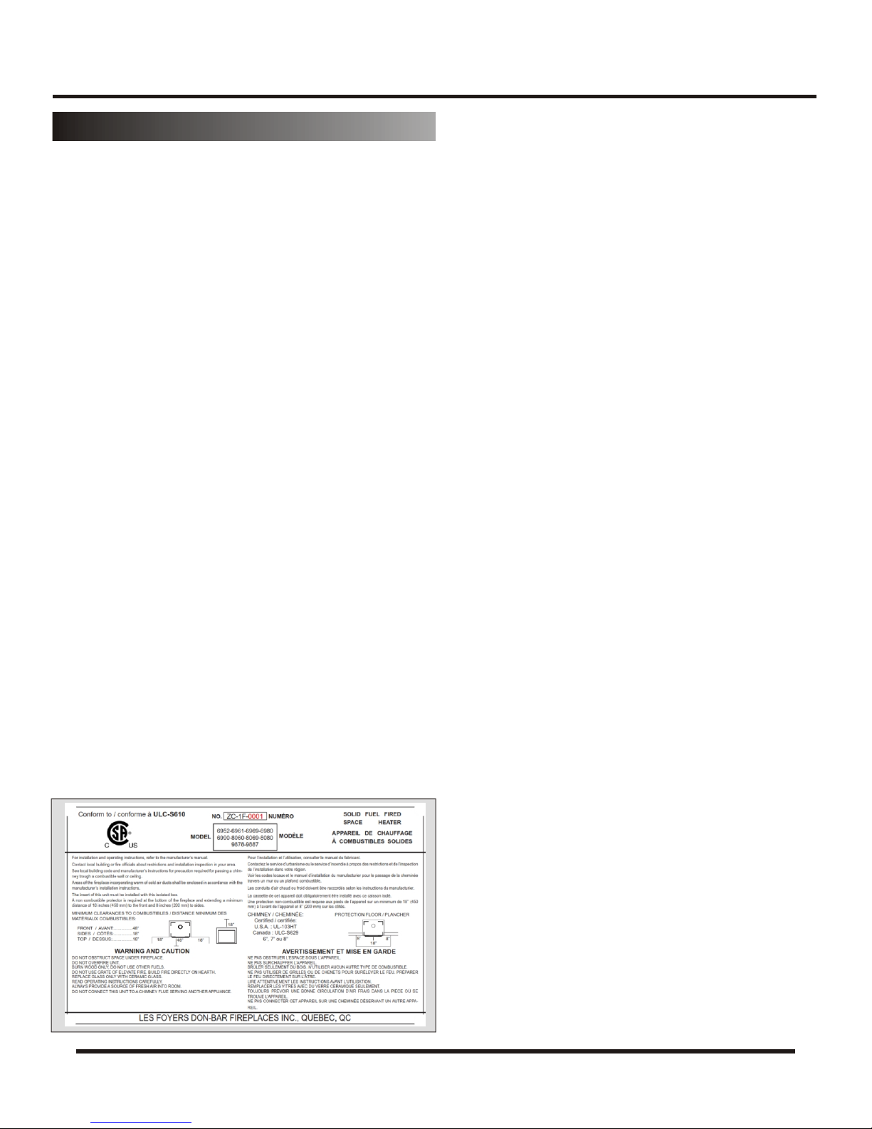
1.1 Modifications: Any modification, change, or
substitution of any fireplace component and/or not
following the installation, operation, and
maintenance instructions will void the warranty and
can put your security at risk.
This unit is designed to receive only a Don-Bar
Insert. No other insert model can be installed
without ULC / UL approval.
1.2 Installation instructions: Before installation
begins, carefully read the manual and contact your
local building department to determine whether a
building permit is required to install a fireplace.
1.3 Applicable Codes: The installation must follow
the instructions in this manual and local building
codes. If there is a conflict, you must follow the
more restrictive measures.
HANDLE THE GLASS DOOR WITH CARE. DO
NOT HIT OR CLOSE THE DOOR SUDDENLY.
DO NOT BUILD FIRE TOO CLOSE TO THE
GLASS. DO NOT CLEAN GLASS WHEN STILL
HOT.
DO NOT USE THE UNIT IF THE GLASS IS
BROKEN OR DAMAGED. REPLACE GLASS
ONLY WITH CERAMIC GLASS.
1.4 Professional installation: For your security,
enlist the services of a professional fireplace fitter for
the installation.
1.5 Before your first fire: Before lighting your first
fire, read the instructions in Part 2 regarding
Security, Operation and Maintenance.
1.6 Log holder prohibited: Do not install a log
holder in the hearth or elevate the fire in any way.
1.7 Listed factory-built chimneys: Your Don-Bar
fireplace is designed to be installed with any 7” (174
mm) I.D. or 8” (200 mm) I.D. prefabricated chimney
bearing the ULC-S629 (2100 degrees) label in
Canada or the UL-103HT label in the USA.
REV. 2014-11
Page 2Page 3
Page 5
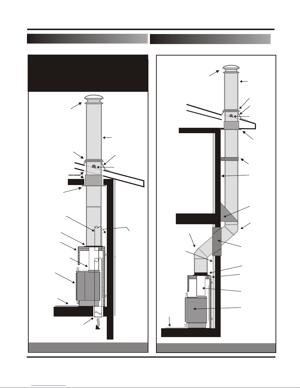
1. Typical interior installation
For an installation in a corner or
inside an insulated exterior chasing
see Pages 12 and 13
Round Top
Factory-built
insulated
chimney
2100 degrees
Flashing
2. Typical exterior installation
Round Top
Factory-built
insulated
chimney
2100 degrees
Storm collar
Flashing
Roof support
Radiation
shield/firestop
Mandatory
2" air space
(50 mm)
Optional warm air
insulated duct
to heat an upper
floor
Chimney
anchor plate
Don-Bar
insulated
case
Don-Bar
insert
Protection for
combustible floors
FIRST FLOOR
15 | 30 | 45 deg. Elbow
Must rest on a
finished surface
(masonry,
Durok, wood,
drywall)
BASEMENT
Protection
for combustible
floors
Wall support
Mandatory
2" (50 mm)
air space
across the
legnth of the
chimney
Offset
support
15 | 30 | 45 deg. Elbow
Wall shield/firestop.
Anchor plate
Don-Bar insulated
case
Rigide stainless
liner 8" (200 mm)
Don-Bar
Insert
Optional warm air
insulated duct with axial fan
to heat the basement
DRAWING 1A
REV. 2016-01
DESSIN NO 1B
Page 4
Page 6
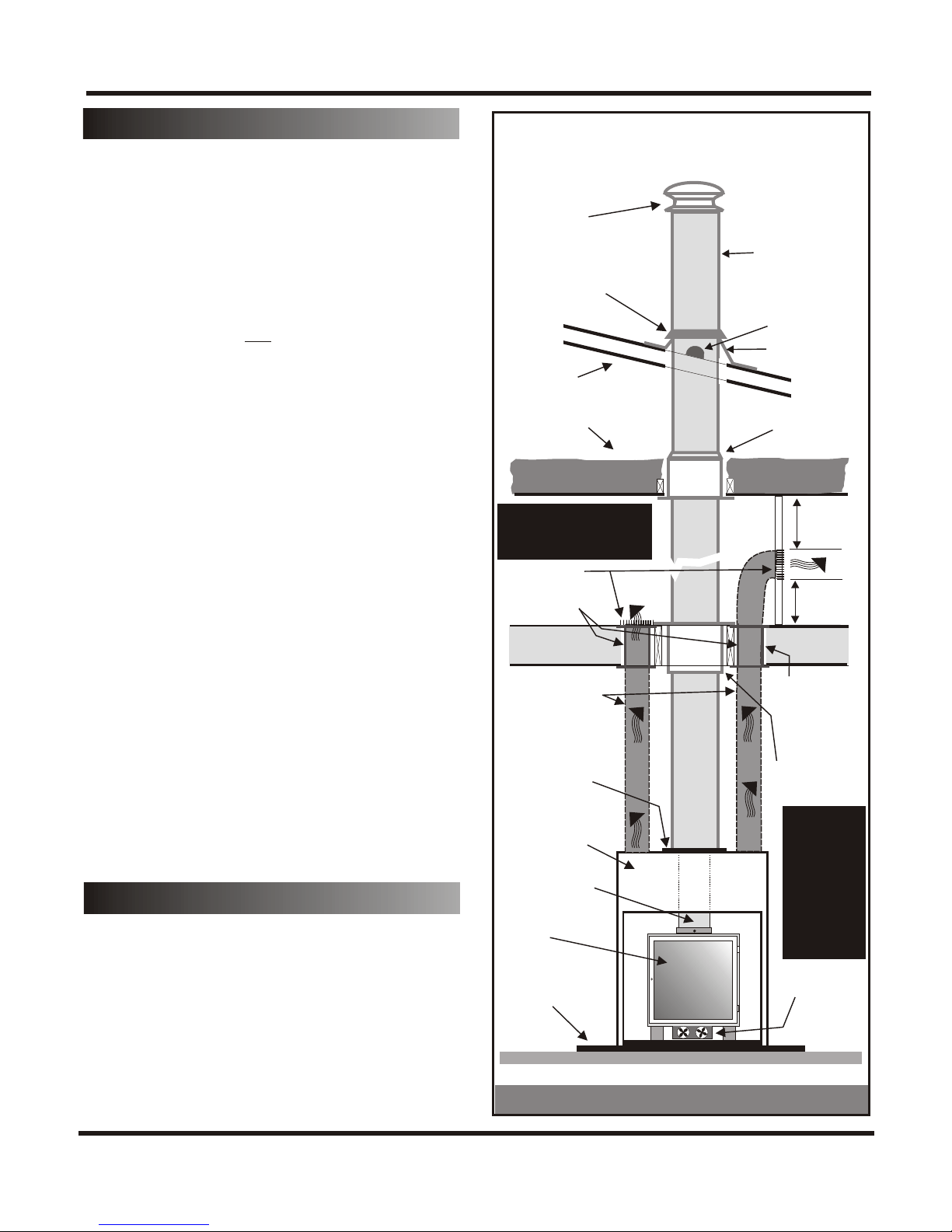
4. . Before beginning the installation
Typical interior installation
4.1 Choosing the best location: Before
beginning the installation, make sure the spot you
have in mind for the fireplace and the chimney
meet the following requirements:
4.1.1 Chimney: Position the chimney to avoid,
as much as possible, offsets, elbows and the
cutting-out of structural elements. The weight of
the chimney must not rest on the insulated
case. Allow at least 2" (50 mm) for air space
between the chimney and any combustible
material including electrical cables, and plastic
plumbing pipes. Never fill this air space with
insulation. For example, if the chimney has an
inside diameter of 8" (200 mm), by adding the
required 2" (50 mm) air space, a 16" (410 mm)
free continuous path is required to install the
chimney. Do not connect this fireplace to a
chimney that is connected to another heating
device.
4.1.2 Chimney minimum height: 15 feet (4600
mm) for proper operation. This length is
measured from the floor where the fireplace is
installed to the top of the chimney.
4.1.3 Minimum clearances from combustible
materials (See Page 13): The location of the
fireplace must meet the minimal specified
clearances requirements from any combustible
material, including furniture, drapes and other
flammable objects. Note that Type X fireresistant gypsum board (Firecode) is considered
combustible for fireplaces installations.
5. Factory-built chimney installation
5.1 Listed parts: Use only ULC or UL listed
parts supplied by the chimney manufacturer when
installing the chimney. The chimney must be
installation in accordance with the manufacturer's
instructions.
with warm air ducts on upper floor
Round top
Storm collar
Roof
Attic
insulation
Note: Warm air ducts
are optional for upper
floor (wall or floor outlets)
Metal grilles
Radiant shield/
firestop
Joist
Metal duct
6" (150 mm) dia.
(flexible or rigid)
insulated 1" (25 mm),
or B-Vent duct
Chimney anchor
plate
DON-BAR
insulated case
Rigid inox liner
8" dia. (200 mm)
DON-BAR
insert
Protection for
combustible
floor
Factory-built
insulated
chimney
2100 degrees
Roof support
Flashing
Attic radiation
shield/firestop
8” minimum
(200 mm)
from ceiling
8” minimum
(200 mm)
from floor
Joist
1” (25mm) min.
clearance from
joists or
manufaturer’s
instructions
Radiant shield/
firestop
Th
e
warm
duct
s used
to
hea
uppe
r flo
gr
av
ity
ris
e as
ve
rtica
a
s po
Optional
fan
t an
s
lly
ss
air
or
hall
ible
by
.
REV. 2016-01
DRAWING 2
Page 5
Page 7
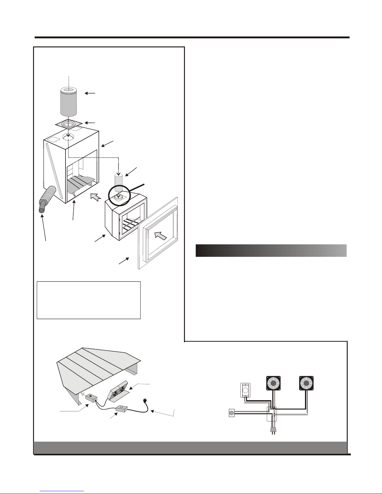
Jointing the chimney to the
insulated case
Factory-built
insulated chimney
2100 degrees
Chimney anchor
plate
5.2 Maximum allowed offsets: Don't install
more than 4 elbows in the chimney. Offsets
cannot be more than 30 degrees from the vertical
axis. The sum of all offsets (elbows) must never
exceed the number 120. For example, maximum
allowed offsets would include: two 30-degree
offsets (4 elbows x 30 degrees =120) or an offset
of 30 degrees plus another one of 15 degrees (2
elbows x 30 degrees + 2 elbows x 15 degrees =
90).
Raised base
Outside air
intake: 4" (100 mm)
flexible insulated duct
Don-Bar Insert
2 ventilated frames plus
1 flat ventilated frame, 4 sides
Do not connect the air intake
to an attic or a garage or
a room that can be under
negative pressure.
Don-Bar insulated
case
Rigid stainless
chimney liner same
dia. as the chimney
See details on
Drawing 4
5.3 Radiation shield/firestop: Install a radiation
shield/firestop every time the chimney passes
through a combustible wall or ceiling.
5.4 Chimney weight: The weight of the
chimney must be supported at regular intervals
according to the manufacturer's instructions. The
weight of the chimney must never be
supported by the Don-Bar insulated case. In
addition, offset supports must be installed above
and as close as possible to each offset (elbow) in
the chimney.
6. Anchor plate installation
6.1 Fixing the anchor plate to the insert: Bolt
the anchor plate (Drawings 3 and 4) on the insert
with the furnished bolts. Take care to insert a
fiberglass sealing gasket between the anchor plate
and the top of the insert to eliminate any smoke
leak.
Raised base details
Thermodisc
under the
base
Speed control
DESSIN NO 3
DRAWING 3
REV. 2016-01
Axial fans (2)
to insert under the base
Electric cable
with 120 V plug
Page 6
Fan wiring
Thermodisc
Speed
control
Axial
fans
120V Plug
Page 8
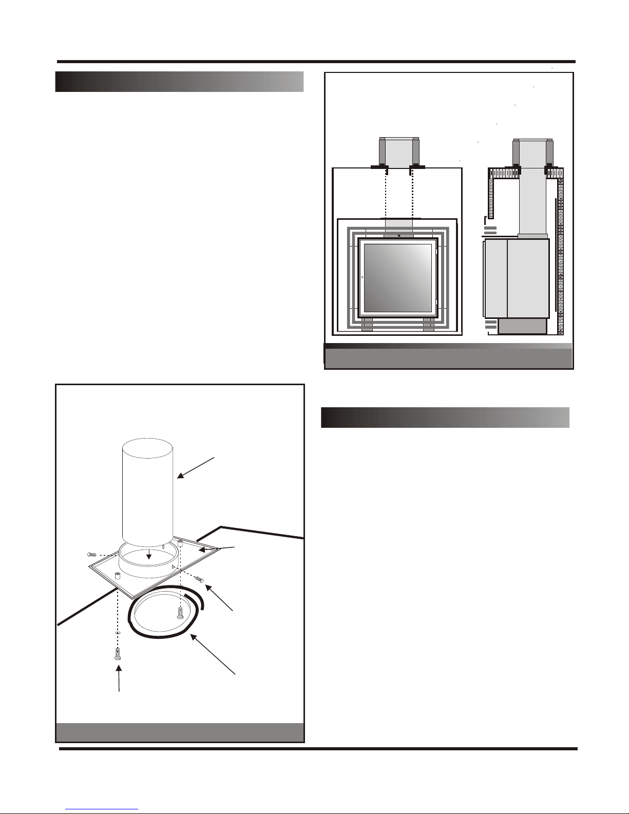
7. Insert installation
The insulated case with the insert
7.1 Raised base: The insert is installed on a 6.5"
(165 mm) high raised base as indicated on
Drawing 3. The raised base can be fitted with 2
optional fans. The raised base is factory installed.
The insulated case must be fixed on the floor.
7.2 Insert positioning: Slip the insert on the
raised base into the insulated case and adjust the
alignment.
7.3 Stainless steel liner installation: Secure to
the anchor plate bolted on the top of the insert a
rigid stainless chimney liner of the same
diameter as the chimney. The height of the liner
must be 1/4" (6 mm) below the insulated case top.
Secure the liner to the anchor plate with 3
stainless steel screws as indicated in Drawing 4.
Securing the anchor plate and the
liner to the insert
Rigid stainless chimney liner
same dia. as the chimney
with a length 1/4"
(6 mm) lower than the top
of the insulated case.
Anchor plate
and the chimney assembly
DRAWING 5
8. Factory-built chimney installation
8.1 Securing the anchor plate for the factorybuilt chimney: Use a standard factory-built
chimney anchor plate for securing the chimney to
the insulated case. Screw the anchor plate to the
insulated case top with 4 metal screws. Join the
anchor plate to the stainless rigid liner already
secured to the insert. The male end of the anchor
plate must slip into the stainless rigid liner for the
condensation water to drip and stay inside the
liner.
Bolt for securing the adaptor
to the insert from inside
DRAWING 4
REV. 2016-01
Stainless screws
(minimum 3,
equally
spaced)
Fiberglass
stove gasket
1/2" (6 mm)
8.2 Chimney lengths installation: Continue
with the installation of the chimney by
positioning lengths with the male end up. The
attic insulation must never be in contact with the
chimney. Allow at least 2" (50 mm) for air space
between the chimney and any combustible
material.
Page 7
Page 9
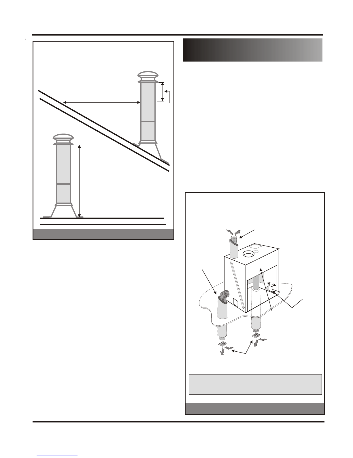
Chimney minimum height above
the roof
10 feet (3 m) Radius
2 feet min (610 mm) min.
3
fe
e
t
(1
m
)
m
i
DRAWING 6
8.3 Minimum chimney height above the
roof: (Drawing 6): Extend the chimney at least 3
feet (1 m) above the roof or 2 feet (610 mm)
above any construction element within 10 feet (3
m) of the chimney.
Warning: Lateral roof braces need to
n
.
be installed when the unsupported
chimney height above the roof
is more than 6 feet (2 m).
9. Heating ducts installation
(Optional)
9.1 Heating an upper or lower floor
(Drawings 7 and 8): Your Don-Bar Zero
Clearance Fireplace is designed to permit the
heating of another floor - upper or lower. For this
reason, openings have been provided into the
sides of the insulated case to allow for the
installation of insulated heating ducts of 6" I.D.
(150 mm).
9.2 Heating a lower floor: The heating of a
basement requires the installation an insulated
duct with an axial fan. The insulated duct can run
inside or outside the insulated case (Drawings 7
and 8).
Installation alternatives for the
optional warm air ducts
Lower floor
heating duct
(at right, left
or behind the
insulated case)
Duct for heating by gravity an
upper floor (at right, left or both,
on the top of the insulated case.)
Outside air intake,
4" (100 mm) I.D.
(optional) with a
sliding mecanism
(left or right). Use
only a flexible
aluminium duct with
a non combustible
vapour barrier.
8.4 Flashing water tightness: Install a metal
roof flashing with a storm collar where the
chimney pass meets the roof. Seal the joint
between the chimney and the storm collar and the
joint between the roofing and the flashing.
8.5 Roof braces: Any chimney that extends
more than 6 feet (2 m) above the roof needs to be
laterally strengthened with a pair of telescopic
roof braces.
8.6 Chimney top: Install a chimney round top
at the end of the chimney.
REV. 2016-01
Lower floor
heating duct (preinstalled duct - left
or right)
Axial fans, 105, 245 or 438 cfm
(to slip and secure inside the duct)
Heating ducts must be made of metal,
6" (150 mm) I.D., with a 1" (25 mm) fiberglass insulating jacket
finished with an aluminized covering.
DRAWING 7
Page 8
Page 10
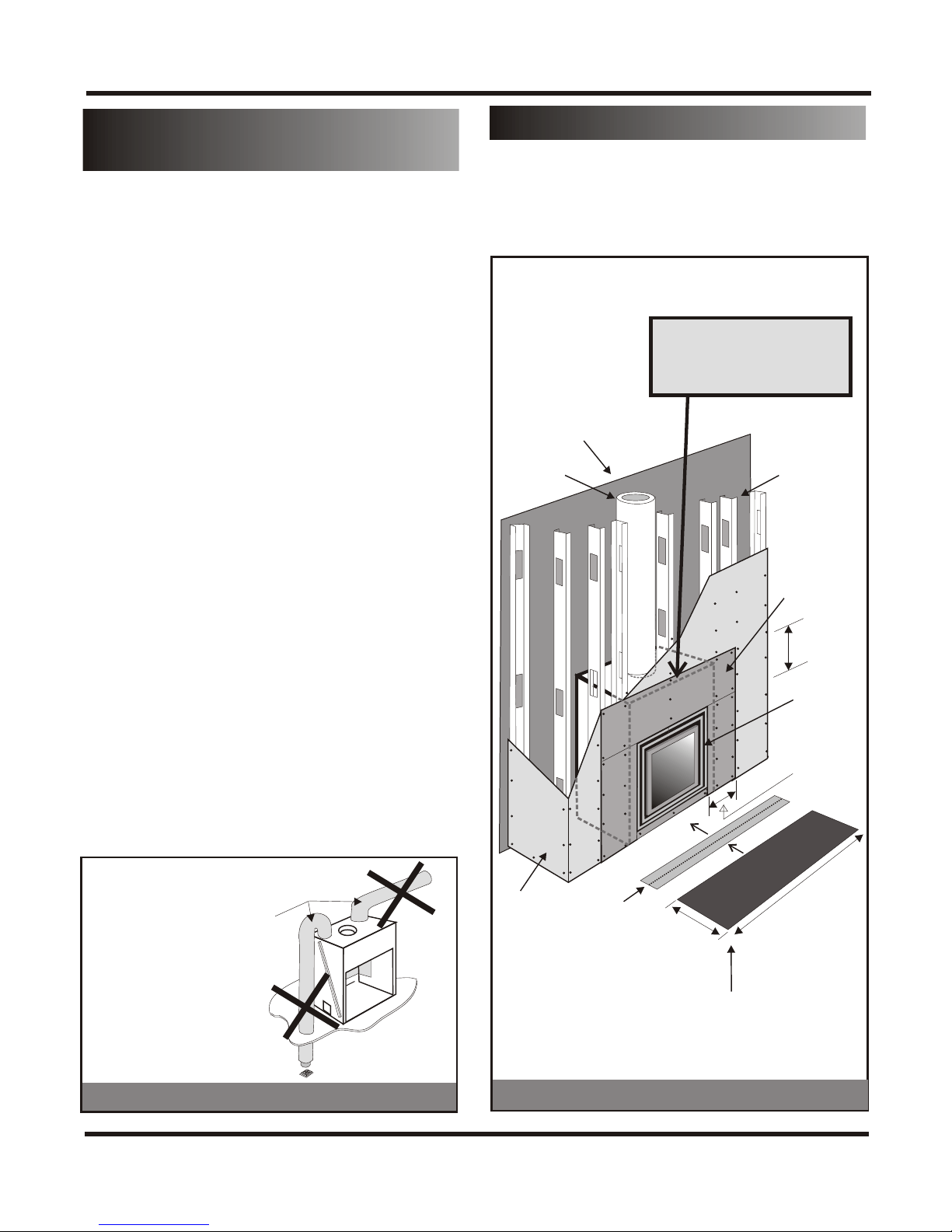
9. Heating ducts installation
10. Fireplace finishing
(Optional) Cont'd
9.3 Axial fan installation: The axial fan for
basement heating must be installed near the
basement ceiling at the end of the heating duct.
The easiest way to secure the fan in place is to
insert it into the heating duct and use a t-wrap
around the duct to tighten the fan.
9.4 Recommended ducts for heating: Use only
non combustible ducts of 6" (150 mm) I.D.
insulated with a fiberglass layer and a flexible
protective covering. (total: 8" / 200 mm O.D.)
Don't use ducts that have an inner side made of
combustible plastics.
9.5 Heating an upper floor (Drawings 2, 7, 8):
The heating of an upper space shall be done by
gravity only, without a fan, by using the outlets
provided on the top of the insulated case. For the
best results, the duct must be installed in a
vertical position without offsets that could reduce
the airflow. The duct can be secured on the top of
the insulated case using one of the pre punched
holes, on the left or on the right, at choice. The
outlet grille at the end of the duct must be made
of metal and designed to allow a non restricted
airflow.
9.6
Danger of overheating: Never install the
heating ducts horizontally or downward
because they will overheat and can cause a fire
(Drawing 8).
10.1 Metallic studs mandatories: Use only
metallic studs for the framing around the
fireplace.
Don-Bar insulated case framing
IMPORTANT: The Durok must
rest and be secured directly
Gypsum board or
plywood or particle
board mandatory
behind the insulated
case
Chimney
2100 degrees
against the front of the insulated
case (without any air space)
Metal studs
mandatory
Non combustible board
1/2" (12 mm)
(Durok)
Durok
18" (460 mm)
minimum
Ventilated
frame
Durok
8" (203 mm)
minimum
Danger of overheating
Overheating
here
Never use the outlets
on the top of the insulated
case for heating down
or horizontally, and this,
even with a fan.
DRAWING 8
REV. 2016-01
Page 9
Gypsum board
1/2" (12 mm)
DRAWING 9
Metal band
of 5" (130 mm)
width to
slip 2.5"
(65 mm) under
the insulated
case to protect
against the
infiltration of
embers
18"
(4
6
0
mm)
"
16
Protection for
combustible
floors
an
h
r t
e
or
m) wid
do
s
m
0
las
1
g
4
e
(
th
Page 11

10. Fireplace finishing
Cont'd
consist of:
10.2 Ventilated frame: Prior to framing, install
temporarily the ventilated frame around the insert
in order to facilitate the taking of the
measurements. Leave a 1/8" (3 mm) air space
between the ventilated frame and the framing to
accommodate metal expansion.
10.3 Non combustible cement boards (Durok
or Unifix): The finishing around the ventilated
frame shall be done with non combustible cement
boards only, Durox, Unifix or equal. These boards
shall not contain wood fibre particles (Drawing
9). The non combustible finishing shall extend at
least 8" (200 mm) on each sides of the
ventilated frame, at least 18" (460 mm) over and
3" (75 mm) below at floor. The joints can be
finished like ordinarily gypsum boards joints or
alternatively, covered with ceramic tiles, marble,
granit.
10.4
insulated case: Above the fireplace door, the
cement boards shall be screwed directly against
the insulated case (no air space) to prevent warm
air from seeping between the box and finishing.
Fixing cement boards against the
.1 Stone tiles or slabs (marble, granite, slate,
etc.) or ceramic at least 3/8" (8 mm) thick,
secured in place;
.2 Concrete or terra-cotta brick, secured in
place;
.3 For temporary floor protection, a sheet of
metal of at least 0.015" (0,38 mm) thickness
or a non-combustible composite cement
board (Durok or Unifix type) of at least 3/8"
(10 mm) thickness may be used.
11.2 Removing the existing resilient flooring:
Prior to installing the floor protection, remove
any existing resilient flooring. (carpet, etc.)
12. Combustible mantel
12.1 Required clearances: See Drawing 12 for
the required minimum clearances if a combustible
fireplace mantel is to be installed.
13. Anti-smoke flap
10.5 Gypsum
of the parts to be protected by incombustible
cement boards indicated in 10.3, the framing of
the fireplace can be covered with gypsum boards.
Finish the joints as usual.
board finish: With the exception
11. Floor protection installation
11.1 Non combustible floor protection: When
the fireplace is installed on a combustible floor, a
non-combustible protection must be placed under
and in front of the fireplace to protect the floor
from falling embers (Drawing 9). A metal strip of
5" wide (115 mm) must be inserted half and half
under the insulated case and under the floor
protection. In addition, the joints of the floor
protection shall be perfectly fitted or filled with
grout. The floor protection must extend at least
18" (460 mm) in front of the fireplace door and
8" (200 mm) on each side. Floor protection may
13.1 Anti-smoke flap (optional): For installation
details, see Drawing 27.
14. 7. Exterior air intake (optional)
14.1 Outside air intake (Drawing 7)
IMPORTANT: The air intake must take air
directly from the outside and not be connected to
an attic or a garage or another interior space
under negative pressure.
REV. 2016-01
Page 10
Page 12
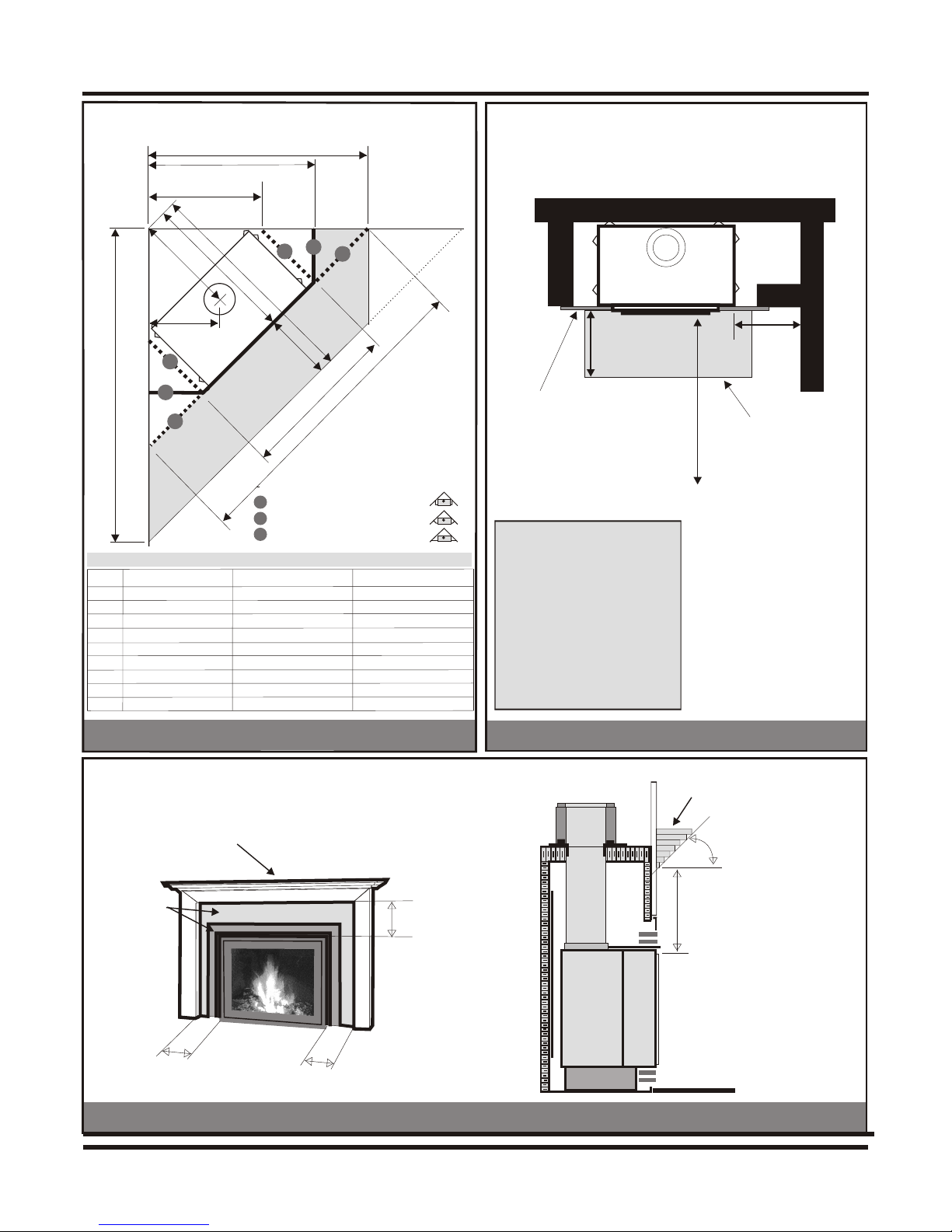
Corner installation
A
B
C
Clearances from combustible
materials
Combustible wall
D
Series 69
A
56-11/16" (1440)
B
46-1/16" (1170)
C
35-1/2" (902)
D
82-1/8" (2086)
F
20-1/4" (514)
G
28-5/8" (727)
H
58-1/16" (1475)
J
40-1/16" (1018)
K
50-1/4" (1276)
80-1/8" (2035)
L
2
G
H
J
1
F
1
2
n
o
ti
c
or
mm
o
te
fl
ro
p
" (457
18
3
There are 3 choices for framing:
Small footprint framing
1
Angle framing
2
Wall to wall framing
3
Series 80
62-7/16" (1586)
50-9/16" (1284)
38-11/16" (983)
87-15/16" (2234)
21-7/16" (545)
30-5/16" (770)
62-3/16" (1580)
44-3/16" (1122)
54-3/4" (1391)
88-5/16" (2243)
3
18" (460 mm)
)
K
L
Non combustible cement
board (Durok type).
8" (200 mm) wide, on
each side of the ventilated frame
and 18" (460 mm) over the frame
(Drawing 9)
DANGER OF FIRE
Series 90/98
66-3/8" (1686)
54-7/16" (1383)
42-9/16" (1081)
91-13/16" (2332)
23-3/8" (594)
33-1/16" (840)
64-15/16" (1649)
46-15/16" (1192)
60-3/16" (1529)
93-7/8" (2384)
Never fill (stuff) with insulation
the empty spaces around the
insulated case and around the
insert. Moreover, non-mineral
insulation (foams, cellulose,
cotton, etc.) needs a minimum
12" (300 mm) clearance from
the fireplace and the
insulated case.
18" (460 mm)
Floor protection:
Shall exceed the width of
the door plus 8" (200 mm)
on each side
Door clearance:
48" (1220 mm)
minimum from
any furniture
combustible
material
C
o
m
b
u
sti
b
l
e
w
a
l
l
DRAWING 10
Clearances for the installation
of a combustible mantel
Combustible
mantel
Incombustible
materials
8
"
(2
0
0
m
m
m
i
n
DRAWING 12
REV. 2016-01
)
i
m
um
8
"
(
2
0
0
m
m
i
n
i
m
u
m
DRAWING 11
Combustible mantel
or shelf
)
m
m
m
u
m
i
IMPORTANT
Combustible
material ARE NOT
allowed at less
than 18 "(460 mm)
over the fireplace
door. Beyond this
height, the width
of any combustible
shelf shall follow
a 45-degree line,
as indicated.
45 deg.
"
8
18"
mm)
460
(
um
m
ni
i
m
m
)
1
0
6
4
(
n
i
m
Page 11
Page 13
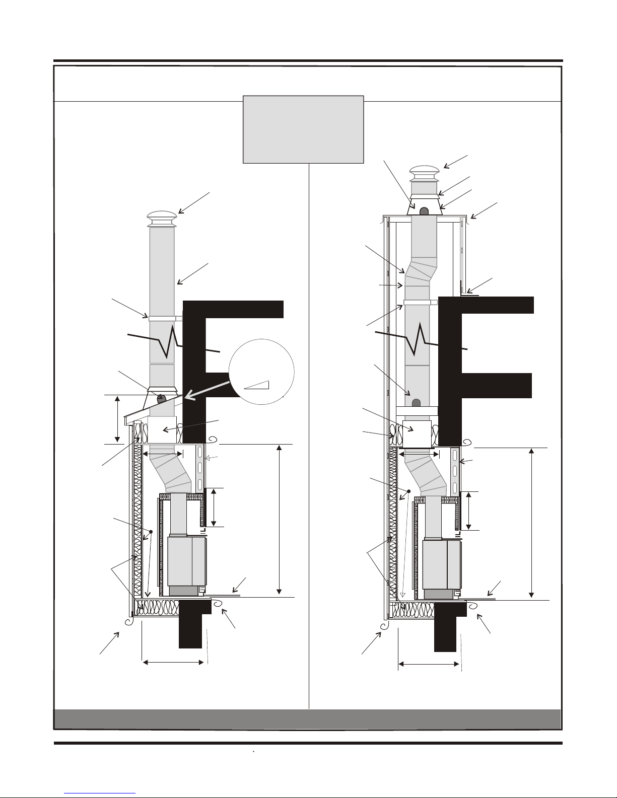
Insulated exterior chasing - Construction details
DANGER OF FIRE
Insulated exterior chasing
with a non covered chimney
Never fill (stuff) with insulation
the empty spaces around the
insulated case and around the
insert.
Insulated exterior chasing
for a covered chimney
roof support
round top
wall bracket
roof support
23" min.
(585 mm)
fiberglass
insulation
MANDATORY:
plywood,
particle or
gypsum boards
fiberglass
insulation
free
space
17" min.
(430 mm)
round top
2100 chimney
7" or 8" I.D.
(180 ou 200 mm)
Maximum
slope for
flashing
12
radiation
shield/firestop
gypsum board
on metal
studs
Durok 18 "
(460 mm)
floor
protection
18" (460 mm)
storm collar
chimney flashing
metal
flashing
offset
to center the
chimney
2100 chimney
7" or 8" I.D.
(180 or 200 mm)
wall bracket
roof support
84" (2135 mm) min.
radiation
shield/firestop
fiberglass
insulation
MANDATORY:
plywood,
particle or
gypsum boards
fiberglass
insulation
free
space
17" min.
(430 mm)
4
roof flashing
gypsum board
on metal
studs
Durok 18 "
(460 mm)
floor
protection
18" (460 mm)
84" (2135 mm) min.
air barrier
Free depth
See table
Drawing 14
DRAWING 13
REV. 2016-01
vapour barrier
(sealed with the
vapour barrier
of the wall)
Page 12
air barrier
Free depth
See table
Drawing 14
vapour barrier
(sealed with the
vapour barrier
of the wall)
Page 14
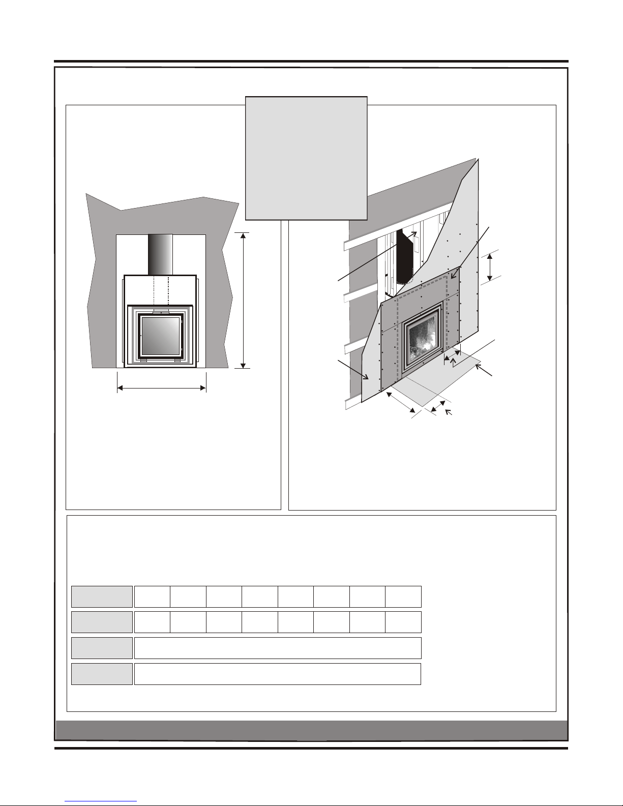
Insulated exterior chasing - dimensions
DANGER OF FIRE
Never fill (stuff) with insulation
Free interior dimensions
of the insulated
exterior chasing
the empty spaces around the
insulated case and around the
insert. Moreover, non-mineral
insulation (foams, cellulose,
cotton, etc.) needs a clearance
from the fireplace and the
insulated case of 12" minimum
(300 mm) .
MANDATORY:
metal studs
Non combustible
protection
Non combustible
cement board
1/2" (12 mm)
(Durok)
Durok
18" (460 mm)
minimum
Exterior wall
thickness (*)
Minimum free
depth
Minimim free
width
Minimum free
height
58" (1470 mm) min.
For the chasing depth:
See the table below
7"
(180 mm)
27"
(685 mm)
8"
(200 mm)
28"
(710 mm)
84" (2135 mm) min.
Gypsum
board
1/2" (12 mm)
1
8
"
m
in
imu
Free depth of the exterior insulated chasing
(varies according to the exterior wall thinkness)
9"
(230 mm)
29"
(740 mm)
10"
(255 mm)
30"
(760 mm)
58"
(1470 mm)
84"
(2135 mm)
11"
(280 mm)
31"
(790 mm)
12"
(305 mm)
32"
(810 mm)
13"
(330 mm)
32"
(810 mm)
(460
m
m)
m
14"
(355 mm)
32"
(810 mm)
Durok
8" (200 mm)
minimum
Non combustible
floor protection:
(Shall exceed the width of
the door plus 8" (200 mm)
8" (203 mm)
minimum
on each side
* The exterior wall inludes
everything from the exterior
finish to the interior finish.
In case of doubt, please
call Don-Bar.
DRAWING 14
REV. 2016-01
Page 13
Page 15
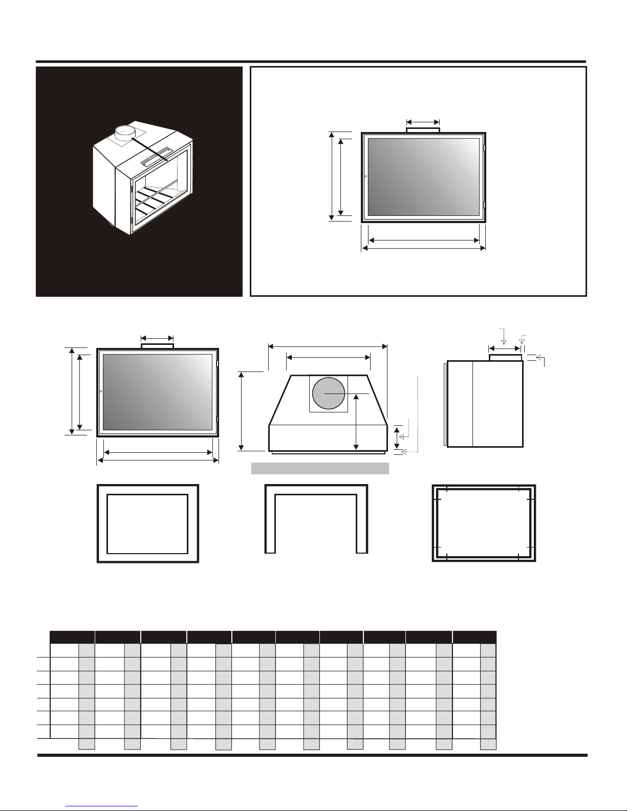
Fireplace insert
7" or 8" I.D.
(175 or 200 mm)
Not to scale
7" or 8" I.D.
(175 or 200 mm)
D
J
C
i
NOT TO SCALE
7" or 8" I.D.
i
(175 or 200 mm)
1" (25 mm)
O
D
J
M
P
1-1/16" (28 mm)
6 " (154 mm)
C
i
Flat frame 4 sides Flat frame 3 sides
Note: Flat and ventilated frames can be also made to measures.
69-52 69-61 69-69 69-80 69-90 80-60 80-69 80-80 98-78 98-87
69-52 69-61 69-69 69-80 69-90 80-60 80-69 80-80 98-78 98-87
24”
I
J
C
D
M
O
P
610
17-3/8”
441
19-3/4”
502
13”
330
19-1/4”
489
17-1/4”
438
14-1/4”
362
mm
24”
21”
19-3/4”
13”
19-1/4”
17-1/4”
14-1/4”
610
24”
533
24”
502
19-3/4”
330
19-3/4”
489
19-1/4”
438
17-1/4”
362
14-1/4”
mm
610
533
502
502
489
438
362
mm
24”
28-1/4”
19-3/4”
19-3/4”
19-1/4”
17-1/4”
14-1/4”
610
24”
718
32-1/4”
502
19-3/4”
502
24”
489
19-1/4”
438
17-1/4”
362
14-1/4”
mm
Optional frames
610
28-1/4”
819
20-3/8”
502
24”
610
16”
489
21-1/4”
438
17-1/4”
362
16-1/4”
mm
718
28-1/4”
518
24”
610
24”
406
16”
540
21-1/4”
438
17-1/4”
413
16-1/4”
mm
718
28-1/4”
610
28-1/4”
610
24”
406
19-3/4”
540
21-1/4”
438
17-1/4”
413
16-1/4”
mm
718
718
610
502
540
438
413
mm
33-1/2”
25-3/4”
29-1/4”
21-1/4”
21-1/4”
21-1/8”
16-1/4”
Ventilated frame 3 sides
or 4 sides
851
33-1/2”
851
756
29-3/4”
654
743
29-1/4”
743
540
21-1/4”
540
540
21-1/4”
540
537
21-1/8”
537
413
16-1/4”
413
mm
mm
3-1/8" (79 mm)
REV. 2016-01
Page 14
Page 16
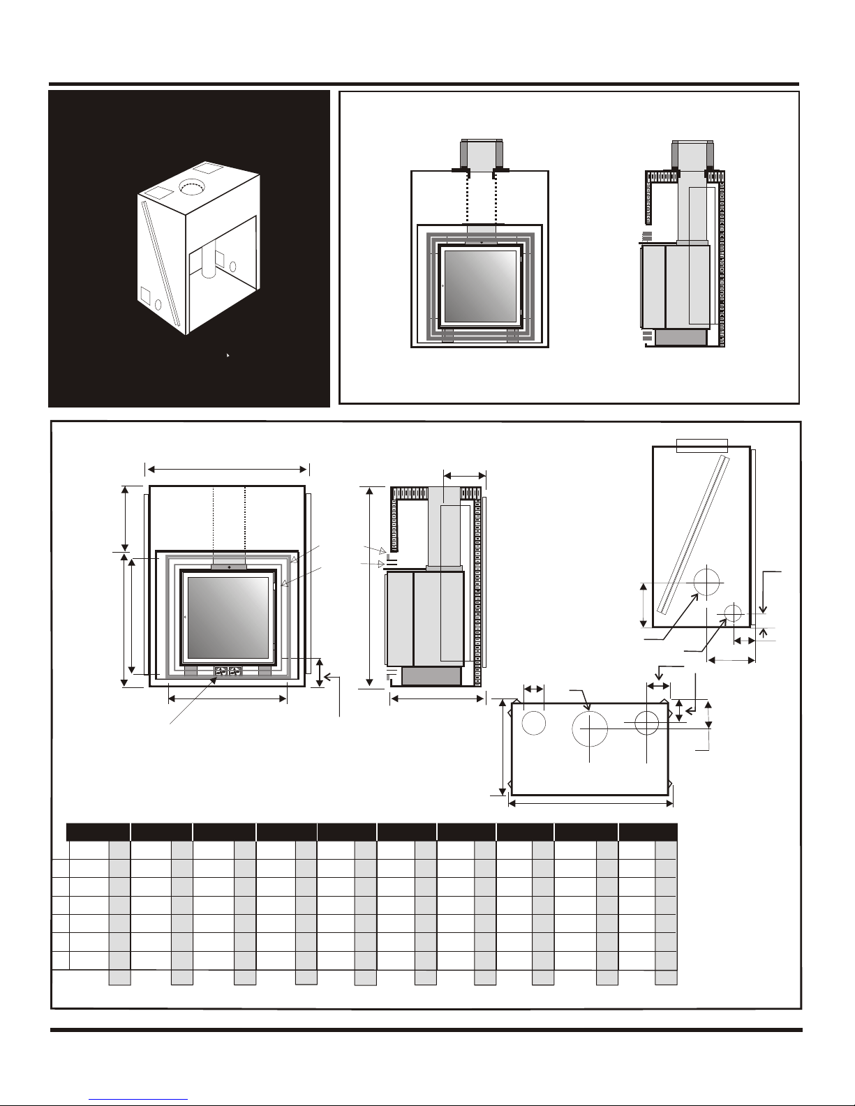
Don-Bar Insulated Case
Not to scale
*S
11 1/2”
c
T
U
Y
Optional:
2 axial fans of 5" (125 mm)
under the raised base
X
finishing
cover joint
ventilated
frame
R
9" (230 mm)
*Q
*Q
Ø 6”
TYP.2
Ø 9”
c
13 1/16”
Ø 6”
c
*S
69-52 69-61 69-69 69-80 69-90 80-60 80-69 80-80 98-78 98-87
591
23-1/4”
*Q
1448
57”
R
946
37-1/4”
*S
746
29-3/8”
T
695
27-3/8”
U
762
30”
X
651
23-5/8”
Y
mm
*Q and *S - spacers included
23-1/4”
57”
37-1/4”
25-3/4”
31”
30”
27-1/4”
591
23-1/4”
1448
57”
946
37-1/4”
654
22-3/4”
787
34”
762
30”
692
30-1/4”
mm
591
23-1/4”
1448
57”
946
37-1/4”
578
18-1/2”
864
38-1/4”
762
30”
768
34-1/2”
mm
591
23-1/4”
1448
57”
946
37-1/4”
470
14-1/2”
972
42-1/4”
762
30”
876
38-1/2”
mm
591
25-1/4”
1448
57”
946
42- 1/2”
368
26-1/2”
1073
30-3/8”
762
34-1/4”
978
26-5/8”
mm
641
25-1/4”
1448
57”
1080
42- 1/2”
673
22-3/4”
772
34”
870
34-1/4”
676
30-1/4”
mm
641
25-1/4”
1448
57”
1080
42- 1/2”
578
18-3/4”
864
38-1/4”
870
34-1/4”
768
34-1/2”
mm
641
1448
1080
476
972
870
876
mm
25-1/8”
57”
48-1/4”
21”
35-3/4”
39-1/2”
32”
638
25-1/8”
1448
57”
1226
48-1/4”
533
17-1/4”
908
39-3/4”
1003
39-1/2”
813
36”
mm
638
1448
1226
438
1010
1003
914
mm
Ø 4”
11 1/2”
5 1/16”
10 7/8”
7”
REV. 2016-01
Page 15
Page 17

PART 2: SECURITY, OPERATION AND MAINTENANCE
1. General operation 7. Glass firescreen maintenance
1.1 Combustion control 7.1 Glass maintenance
1.2 Air intake control 7.2 Replacing a glass pane
1.3 Smoke outlet control 7.3 Door gaskets
1.4 Danger of burns
8. BBQ installation
2. Precautions before lighting your
first fire
2.1 Adequate air supply
2.2 Preventing smoke returns 9.1 Creosote build-up and removing
3. Firewood
3.1 Allowed fuels
3.2 Forbidden fuels
3.3 Recommended wood species 9.1 Firescreen
3.4 Green wood
4. The fire
4.1 Opening the high efficiency HE smoke damper
4.2 Open fires
4.3 Controlled combustion fires
4.4 How to start a fire
4.5 Firescreen is mandatory with open fires
4.6 Preventing overfiring
4.7 Forbidden flammable liquids
4.8 Smoke release during the first fire
4.9 Caution: Very hot!
4.10 Gloves and poker
4.11 Smoke detector
8.1 BBQ grill installation
9. Chimney maintenance
9.2 Inspection and regular maintenance
9.3 Soot build-up removal
10. Firescreen
11. Anti-smoke flap
9.1 Anti-smoke flap installation
13. Humidity and condensation
13.1 Excessive humidity and condensation
5. Ashes
5.1 Ashes removal
5.2 Metallic container
5.2 Natural fertilizer
6. Fireplace maintenance and protection
6.1 Finish maintenance
6.2 Repainting
6.3 Fireplace storing before installation
REV. 2016-01
Page 16
Page 18
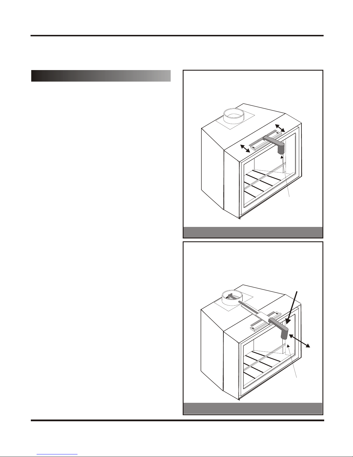
PART 2: OPERATION AND MAINTENANCE
1. General operation
1.1 Combustion control: Two valves are used
to control combustion. The first one (Drawing
20), controls the air intake in the combustion
chamber. The second one control the smoke outlet
(Drawing 21). These two valves are controlled by
the same removable handle.
1.2 Air intake control (Drawing 20): The sliding
valve controlling the air intake is located above
the insert glass door. A special multi-purpose
removable handle is provided to open or close it.
Pull the handle to admit more air into the
combustion chamber. Push the handle to reduce
the air intake. In practice, the best position for
the valve will vary according to three factors: fire
intensity, chimney draught and wood humidity.
As a general rule, a fire will last longer if less air
is admitted in the combustion chamber. If a hot
and blazing fire is wanted, then open the air
intake fully.
1.3 Smoke outlet control: This sliding valve is a
part the of the high efficiency HE deflector
system (Drawing 22). It is located in the middle
of the insert just above the air intake control
(Drawing 21). Use the multi-purpose handle to
operate it. Close it to increase the combustion
efficiency by reburning the gases contained in the
smoke. Open fully to start a fire or when using a
firescreen or the BBQ grill.
1.4 DANGER OF BURNS: Danger of burns by
the excessive heat if the handle is left in place
when using the device. Always remove the
handle and store out of reach of children.
Using the removable handle to
control the air intake
d
e
s
o
l
c
n
e
p
o
Use the handle to
adjust the air
intake
DRAWING 20
Using the handle to control the
HE sliding smoke deflector
IMPORTANT: Always
open this key before
opening the door or
lighting a fire
o
l
c
d
e
s
en
p
o
REV. 2016-01
Use the handle to
control the damper
DRAWING 21
Page 17
Page 19
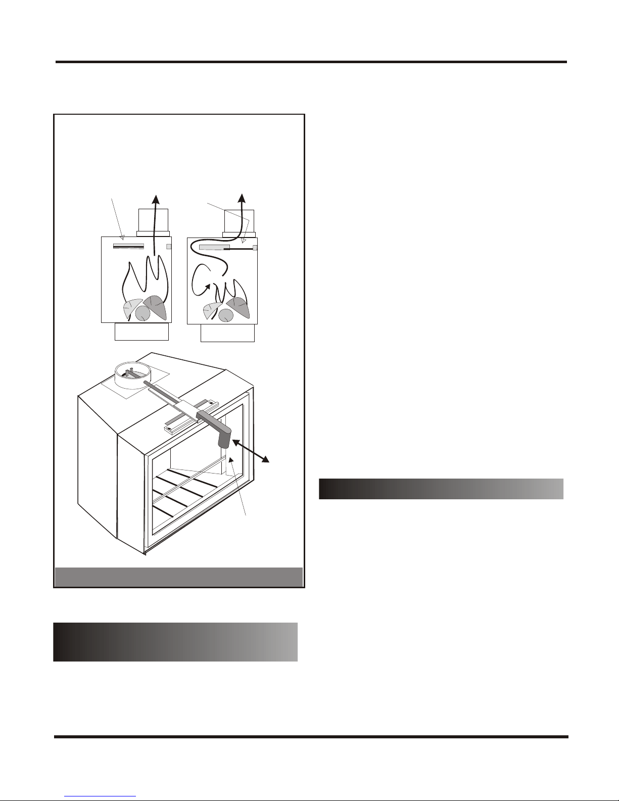
Using the handle to control the
HE sliding smoke deflector
Open fully the smoke damper
to start a fire, when opening the
door or when making
an open fire with the firescreen
Close the smoke damper
for a long-lasting high efficiency
fire (close the door first).
d
e
s
o
l
c
supply to maintain the combustion. If the room is
under a negative pressure, if the house is too
airtight, or if a ventilation device is in operation it
may be necessary to open a door or a window to
compensate.
2.2 Preventing smoke returns: Your fireplace
is designed to operate without smoke returns
during normal operating conditions and when
installed according to the instructions outlined in
the manual. However, some conditions out of our
control can create smoke returns. Don-Bar
Fireplaces cannot guarantee the absence of smoke
returns but if this phenomenon occurs special
attention should be given to the following
situations: mechanical ventilators in operation
(kitchen hood, dryer, air heating system, air
exchanger), drafts, room or house negative
pressure, inadequate chimney height, exterior
structures harmful to the chimney draft or capable
of causing smoke returns, an indoor moisture
level that is too high and causes ice build-up in
the flue and reduces chimney draft, too many
elbows in the chimney, crushed outside air intake
n
e
p
o
duct, strong winds, etc.
Use the handle to
control the damper
DRAWING 22
2. Precautions before lighting
your first fire
2.1 Adequate air supply: A wood fire requires
plenty of air. Always be sure there is enough air
REV. 2016-01
3. Firewood
3.1 Allowed fuels: Your fireplace is designed to
burn wood only. To start a fire, use only
newspaper and small pieces of firewood.
3.2 Forbidden fuels: Anthracite, melamine,
pressure treated or painted wood, wood particle
boards and other composite materials. These
materials reach very high temperatures and
release corrosive gases, which may irreparably
damage your installation and void the warranty.
Page 18
Page 20
3.3 Recommended wood species: For an
efficient and economical operation, use only dry
hardwood such as maple, oak, wild cherry, birch,
etc. The use of dry hardwood reduces creosote
formation. Avoid softwoods, coniferous and
green woods. These produce a lot of creosote.
3.4 Green wood: If your firewood is too green,
place it in a well ventilated space, sheltered from
rain, as long as necessary to allow it to dry. Dry
wood is easy to identify: it is cracked at the ends
and much lighter because it contains less water.
the air intake control must be fully open. Always
use a firescreen with an open fire. Note that the
air intake control is inoperative when the door is
open.
4.3 Controlled combustion fires: First, follow
the instructions at 4.2 for open fires. Later,
following the formation of embers, the flame will
be less intense, the chimney flue warmer and you
will be able to close gradually the sliding smoke
damper. You will also be able to close gradually
the air intake control to increase the heating
power of the fire.
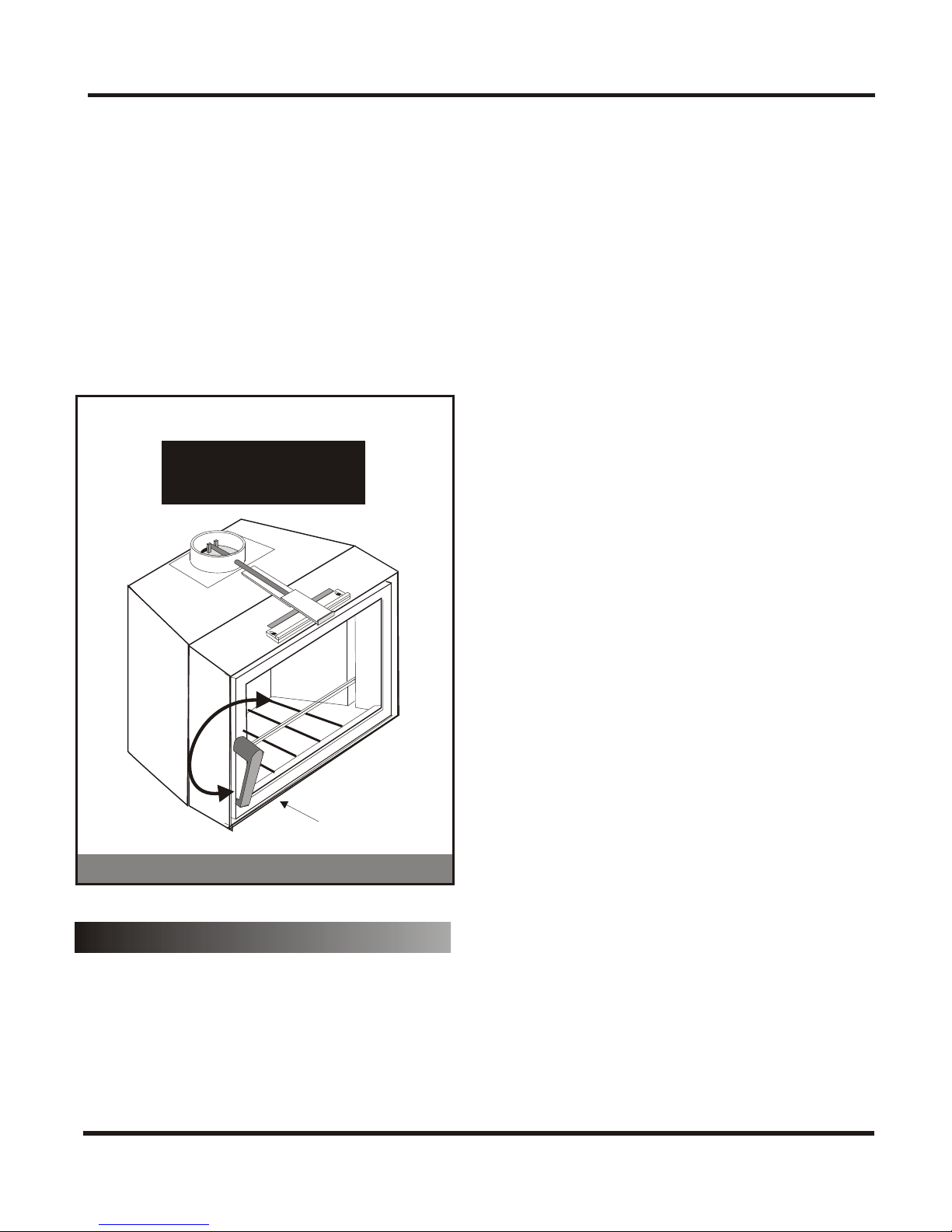
Using the handle to open the door
DANGER OF BURNS
Never leave the handle on the
door during a fire.
Turn the handle
to lock or unlock
the door
4.4 How to start a fire: To light a good fire,
begin by placing 4 or 5 newspaper balls in the
fireplace. Next, place 5 to 8 small pieces of dry
firewood over the newspaper. Then add 2 or 3
small-sized logs. Light the newspaper in 4 or 5
spots. When the small firewood begins to burn,
add 1 or 2 medium-sized logs.
4.5 Firescreen is mandatory when the insert is
used with an open door: In order to prevent
dangerous spark discharges and falling embers,
always use a firescreen (supplied separately - not
shipped with the insert) when making an open
fire.
4.6 Preventing overfiring: Don't overload your
fireplace. Don't make fast and hot fires (such as
those using only paper, cardboard or small wood).
These fires can generate very high temperatures
that may damage your chimney if they last longer
than 2 minutes.
DRAWING 23
4. The fire
4.1 Opening the HE smoke sliding damper:
Before lighting a fire, completely open the smoke
sliding damper. Use the provided handle as
indicated in Drawing 21.
4.2 Open fires: The smoke sliding damper and
REV. 2016-01
Page 19
Page 21

4.7 Forbidden flammable liquids: Never use
flammable liquids or accelerators such as gas,
lamp oil, kerosene, BBQ starters, or other
flammable substances to start or stir up a fire.
Always keep these products away from the fire
when using the fireplace.
4.8 Smoke release during the first fire: It is
possible that, while making your first fire, the
fireplace releases smoke for about 20 minutes.
This smoke release is normal and is usually
caused by the "baking" of the fireplace paint
finish. Open a window and the smoke will
disappear by itself in a few minutes. Caution:
This smoke can trigger a smoke detector causing
a false alarm!
4.9 Caution: Very hot! Your fireplace can
become very hot. Be careful when coming close
to it. Keep clothes, furniture, drapes, pets and
young children away from the fireplace.
potash, phosphorus, and ideal for acidic soils.
6. Fireplace maintenance and
protection
6.1 Finish maintenance: Your fireplace is
covered and protected by a special hightemperature paint finish. Normal maintenance
requires only a simple dusting using a dry and
soft duster or a feather duster. Avoid splashing
liquids on the fireplace.
6.2 Repainting: If, over time, it becomes
necessary to freshen up the fireplace finish, you
can spray directly on the old finish a coat of
"Stove Bright" high temperature stove paint. The
standard color used by Don-Bar is Metallic Black
no 6309.
4.10 Gloves and poker: In order to operate the
fireplace safely, always keep a poker on hand.
Heat resistant gloves are also recommended and
can be very useful when you have to handle hot
parts during an emergency.
4.11 Smoke detector: For your safety install a
smoke and carbon monoxyde detector in the room
where the fireplace is installed.
5. Ashes
5.1 Ashes removal: Your fireplace must be
emptied regularly. Always keep a bed of ashes of
about 1" (25 mm) in the fireplace to protect the
hearth bottom. A log grate is not recommended.
5.2 Metallic container: To collect ashes, use a
metal container with an airtight lid.. Dispose of
them on the ground, outside, away from any
combustible material. If you plan to bury ashes
or dispose of them another way, keep them in an
airtight container until completely cooled.
6.3 Fireplace storing before installation: To
prevent rusting, always store the fireplace and its
components in a dry space.
7. Glass firescreen maintenance
7.1 Glass maintenance: To clean the glass,
begin with a duster and, preferably, a stove glass
cleaner. These aerosol glass cleaners are sold by
stove and fireplace dealers. They are specially
formulated to dissolve creosote without damaging
the glass. Then, to get a sparkling surface, finish
with a clean duster and a domestic glass cleaner
such as Windex. Warning: Wait until the glass
has completely cooled before attempting to clean
it. Never use an abrasive cleaner on the glass.
7.2 Replacing a glass pane: If a glass pane
shatter, replaced it with a 5 mm ceramic glass
pane of the same dimensions.
5.3 Natural fertilizer: Ashes are useful as
natural plant fertilizer. They are rich in lime,
REV. 2016-01
Page 20
Page 22
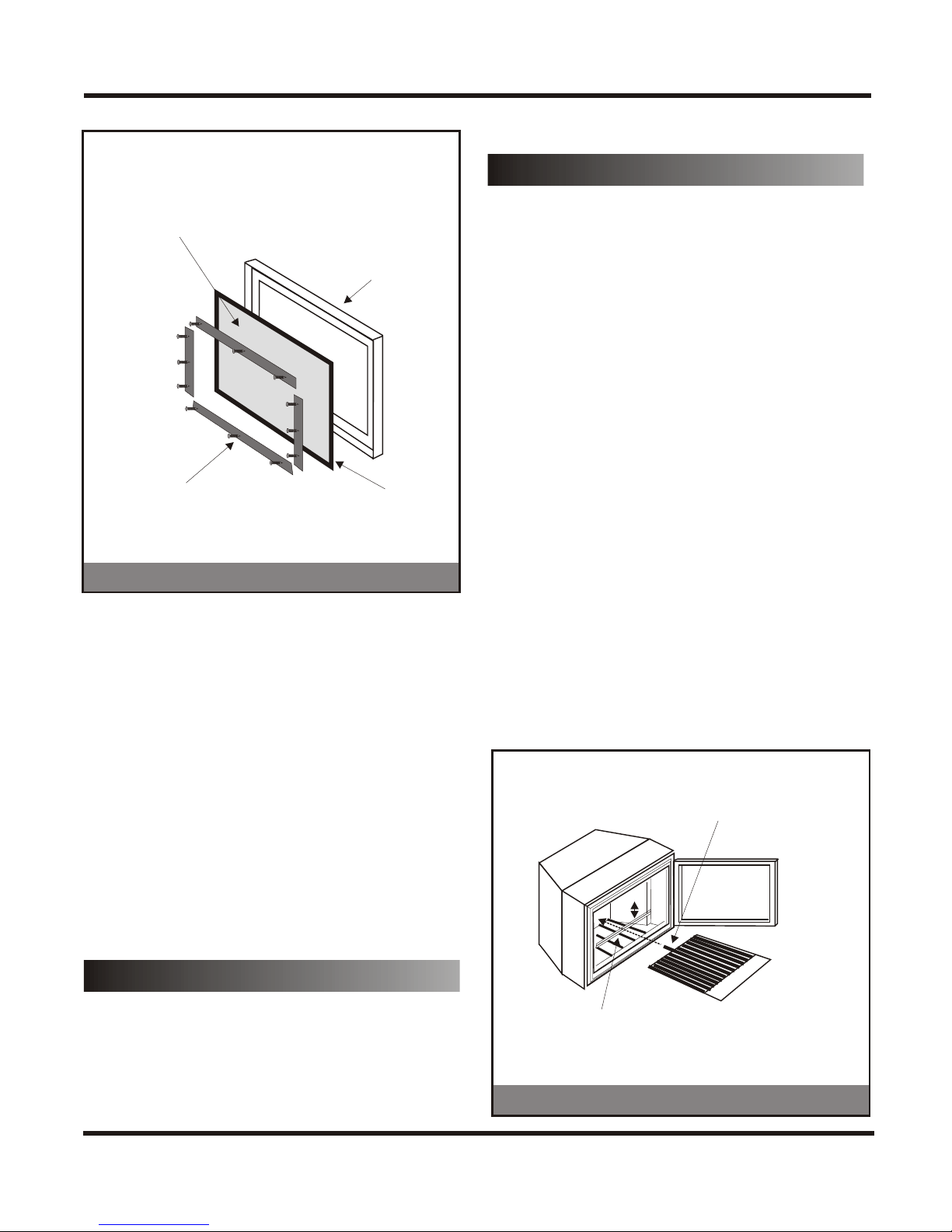
back of the fireplace (Drawing 25).
Glass Pane Replacement
5 mm ceramic glass
Securing strips
and screws
DRAWING 24
Insert door
1/2" (12 mm)
U-shaped gasket
9. Chimney maintenance
9.1 Creosote build-up and removing: When
wood burns slowly, tar and organic vapors are
released. These combustion by-products combine
with moisture to form creosote. When creosote
vapor comes in contact with a relatively cold
surface, such as a chimney flue during a slow
burning fire, it condensates. As a result, creosote
residues build up inside the chimney. When this
creosote deposit catches fire, the chimney can
reach dangerously high temperatures.
9.2 Inspection and regular maintenance: The
chimney must be inspected regularly during the
heating season in order to determine whether is
creosote build-up. In order to avoid chimney
fires, the chimney must be cleaned if the creosote
build-up reaches a 1/8" (3 mm) thickness.
The ceramic replacement glass (pyroceram) can
usually be ordered from a local glazier or ordered
directly from Don-Bar Fireplaces. (Note: the
glass panes are not warrantied against breaking).
Warning: Never replace a broken door glass
with an ordinary or tempered glass: it will
shatter and may cause serious injuries.
7.3 Door gaskets: The gasket ensuring the door
airtightness must be changed periodically.
Replace it with a similar fiberglass 3/8" (10 mm)
round stove gasket. To replace the gasket around
the glass, use a U-shaped 1/2" (12 mm) fiberglass
stove gasket.
8. BBQ grill installation
8.1 BBQ grill installation: First, adjust the
height of the metal rod supplied with the grill to
support it at front. The BBQ grill is set in place
by simply inserting the central long rod into one
of the holes provided on the hearth plate at the
BBQ grill installation
Adjust the height
of the support rod
DRAWING 25
Insert the central long rod
into one of the holes
provided on the back
hearth plate
REV. 2016-01
Page 21
Page 23
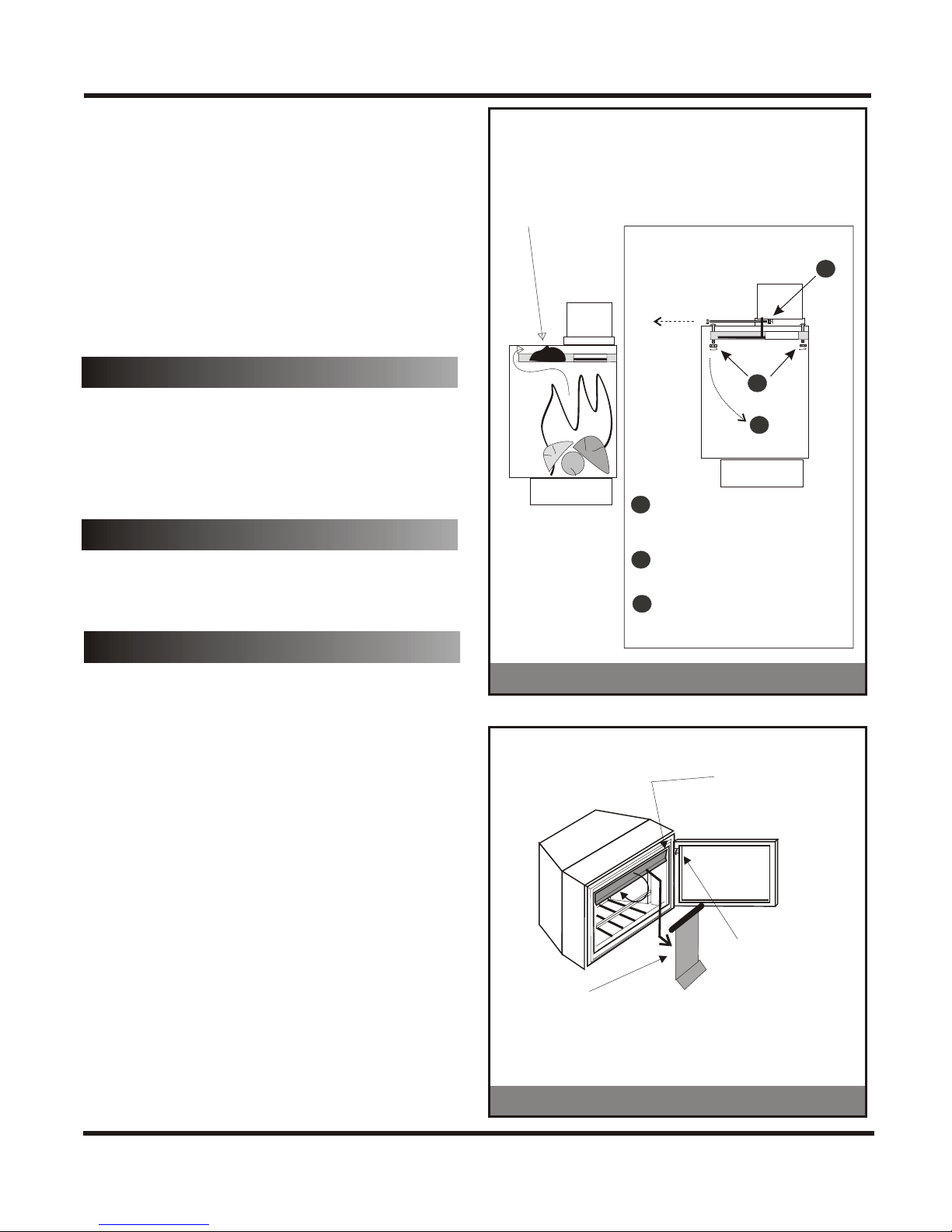
9.3 Soot build-up on the HE smoke sliding
deflector (Drawing 26): During the chimney
cleaning, be sure to remove any creosote or soot
build-up over the HE smoke deflector. The buildup of soot on the deflector can prevent the flow of
smoke. In addition, the sooth accumulation
over the HE plate reduces the efficiency of the
secondary combustion because ash insulates
and lowers the temperature of the secondary
combustion chamber; the HE plate could
overheat and damage over time.
Cleaning of the HE smoke deflector
To prevent soot build-up the
smoke deflector must be
cleaned at regular intervals
Cleaning sequence
1
10. Firescreen installation
10.1 Firescreen: The optional firescreen is
simply put in place in the front of the insert. Just
tilt it a little and slip it into the opening.
Integrated clips will keep it in place.
11. Anti-smoke flap
11.1 Anti-smoke flap installation (optional)::
See details on Drawing 27.
12. Humidity and condensation
12.1 Excessive humidity and condensation: In
winter, high humidity levels inside the house can
cause chimney problems such as condensation,
and ice build-up eventually dripping into the
fireplace. In extreme cases, the condensation
water can even infiltrate the chimney insulation.
To avoid these problems, it is necessary to
maintain a 30-35% humidity level inside the
house.
Unscrew the rod that control
1
the sliding damper. Access the nut
from inside the fireplace.
Unscrew the 4 bolts that
2
hold the smoke deflector.
Take out the deflector. Tilt it down
3
to unhook it from its bracket
on the back of the fireplace.
DRAWING 26
Anti-smoke flap installation
(optional)
Slip the pins at the ends
of the flap into the
predrilled holes on each
side of the insert
2
3
REV. 2016-01
Install this way
The anti-smoke flap comes down automatically when opening
the door. It raises when the door is closed.
DRAWING 27
Page 22
Screw the small plate
retaining the arm into
the predrilled holes
on the door frame
Page 24
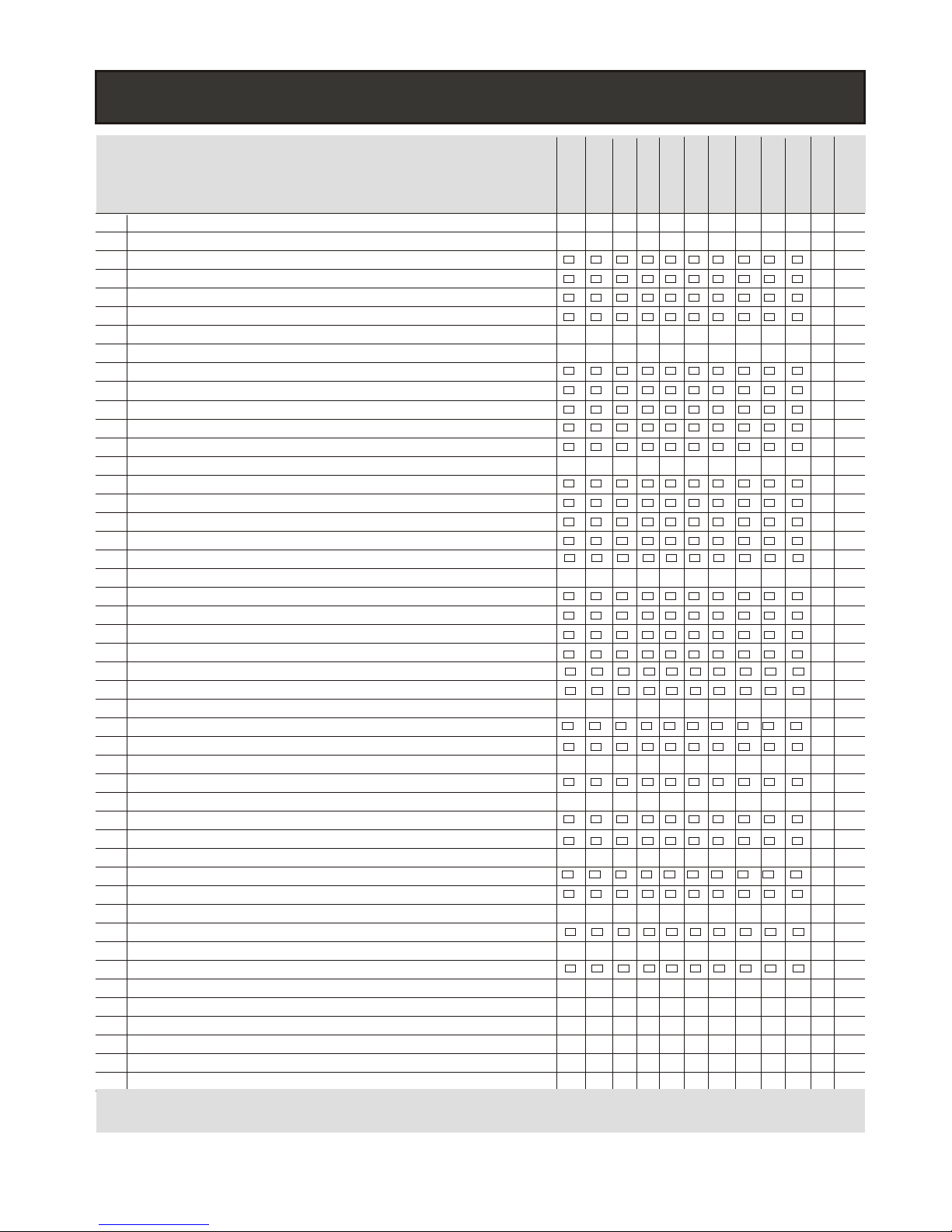
PART 3: REPLACEMENT PARTS LIST
To order a part:
1) Check the replacement part required
2) Specify the year of the fireplace installation _________________
3) Fax this list with your coordinates to 418-686-9117
HE Combustion System
Sliding damper
Deflector (without the sliding damper)
Rod and plate assembly for the sliding damper
Chimney adaptor
Standard Parts
Sliding plate for air intake control
Hearth plate (rear)
Herath plate (left)
Hearth plate (right)
Anti-smoke flap
Insert door including glass retaining bars
Ceramic glass, 5 mm
Glass retaining bars only (2 short, 2 long)
Glass pane gasket
Door gasket
69-61
69-52
69-69
69-80
80-60
69-90
80-69
80-80
98-87
98-78
Tilted fan assembly (2) to slip under the raised base
Side fan assembly (1)
Centrifugal fan
Insulated box for the centrifugal fan
Thermodisc
Speed control
Levelling plate complete with levelling bolts
Raised triangular base
Metal firescreen
BBQ grill
BBQ gril support rod
Ventilated frame (3 sides)
Ventilated frame (4 sides)
Fireplace handle (to operate the fireplace)
Sliding damper assembly for the exterior air intake
REV. 2016-01
Page 23
Page 25

PART 4: CHIMNEY FIRES
DIRECTIVES IN CASE OF A CHIMNEY FIRE
How to detect a chimney fire
- Odour: Smell of smoke in the air.
- Sight: The colour of the pipe change. Flames at
the top of the chimney on the roof.
- Hearing: Abnormal rumbling.
How to avoid chimney fires
- Burn only dry firewood.
- Clean the chimney at least once a year before the
heating season or after burning 4 or 5 cords of
firewood.
- Don’t let creosote built-up in the chimney.
- Don’t burn coniferous, construction wastes,
or materials containing glues, paints, or other
chemicals.
- Always have a fire extinguisher on hand.
What to do
- Immediately alert the occupants of the building about
the potential danger.
- Call your local fire department or 911.
Cut all the sources of air that can feed the
-
fire (windows, air intakes, doors, etc...)
- Evacuate the house.
- Following a chimney fire, don't reuse your fireplace
until a professional has inspected it. A chimney fire
can overheat the chimney components, wrap it
inside, curve, crack or dislocate certain components.
- Do all the recommendations of the professional
and replace any part that is damaged or judged
unsafe.
What NOT to do
Do not throw water on the fire.
-
Do not block the top of the chimney
- .
REV. 2016-01
Page 24
Page 26
LES FOYERS
DON-BAR
FIREPLACES
1. The first 5 years: If, during this 5year period, and in the course of a normal
use, a component part of the fireplace
becomes defective due to a material or
workmanship defect, this part will be
replaced or, at our discretion, repaired
free of charge. The following parts are
excluded from this warranty:
1.1 Hearth back plate, smoke
deflector, HE deflector system,
grate, ash drawer/tray, wood
basket, fireguard, refractories,
metal fire screen, BBQ grill,
electric fan blower: Being subject
to high temperatures, these parts
may have to be replaced from time to
time; this is regarded as normal
maintenance. However, all the
original parts shipped with the
fireplace are warranted against
material or workmanship defects for
1 year following the date of
purchase.
1.2 Chimney: Since the chimney
and its components are not
manufactured by Don-Bar, please
refer to the warranty of the chimney
manufacturer for any claim about it.
1.3 Fireplace paint finish: The
fireplace is painted with a high
temperature paint that needs to be
freshen up from time to time.
However, the original finish applied
to the fireplace is warranted for 1
year following the date of purchase.
The warranty is limited to the supply
of the paint required for repainting
the fireplace.
25 YEAR LIMITED WARRANTY
1.4 Gaskets: Fireplace gaskets are 8. The duration of the warranty on any
warranted for 90 days following the part that is the object of a claim must
date of purchase. never exceed the total duration of the
original warranty of the part shipped with
2. 20-Year Replacement Plan: After the fireplace.
the expiration of the first 5 years, and for
an additional 20 years period following 9. Draft and smoke returns: All Don-
the date of purchase, we will ship (at the Bar fireplaces are designed and tested to
exception of transport expenses and operate with a positive draft, without
parts described in the articles 1.1, 1.2, smoke returns, when installed according
1.3 and 1.4) any defective part for a price to the manu facturer 's inst ructions .
not exceeding 50% of its retail price. Smoke returns caused by environmental
factors (negative pressure, lack of air,
3. These warranties shall never be turbulence, etc.) are not covered by the
interpreted as covering workmanship on present warranty.
site. Don-Bar takes no responsibility for
damages to the building following the
repair or the replacement of any part
covered by the warranty.
4. No representative, employee or agent
of Don-Bar is authorized to change or
extend the present warranty.
5. The warranty is valid only if the
installation, the operation, and the
maintenance of the fireplace have been
done in accordance with the fireplace
manufacturer written instructions.
6. Don-Bar takes no responsibility for any
damage to the fireplace, the chimney or
the building if fireplace repairs done by
third parties are executed with non
original parts.
7. Any part that is the object of a claim in
accordance with the present warranty
must by returned to the shop (transport
prepaid) with a proof of purchase. All
returns must be approved by the
manufacturer before shipping.
10. The warranty does not cover:
10.1 Broken glass
10.2 Damages caused by a
chimney fire;
10.3 Shipping damages not
reported on delivery;
10.4 Faulty installation;
10.5 Damages caused by
abnormal or abusive use.
10.6
altered or containing substituted
components or when the
instructions for installation,
operation or maintenance have not
been followed.
11. Caution: Improper operation or lack
of maintenance can endanger your
safety.
12. Send any communication or claim to
the following address:
Foyers Don-Bar Fireplaces, inc.
741, St-Vallier Ouest, Québec,
(Quebec) Canada G6V 3N9
Phone: 418-686-9114
Fax: 418-686-9117
Website: www.don-bar.com
Email: [email protected]
Any fireplace modified,
REV. 2016-01
Page 25
 Loading...