

DOMUSA TEKNIK SANIT 300, SANIT 500, SANIT 750, SANIT 1000, SANIT 1000 SBH Installation And Operating Instructions Manual

INSTALLATION AND OPERATING INSTRUCTIONS
SANIT 300
SANIT 500
SANIT 750
SANIT 1000
SANIT 1000 SBH
ER-0170/1996
CGM-04/392

Thank you for choosing a DOMUSA TEKNIK product. From the range of
DOMUSA TEKNIK products you have chosen the Sanit model, a stainless
steel hot water tank for producing domestic hot water (DHW) by means of
a coil, which together with a DOMUSA TEKNIK heating boiler will provide
the ideal level of comfort for your home, provided it is accompanied by a
suitable hydraulic installation.
This manual forms an essential part of the product and it must be given to
the user. Read the warnings and recommendations in the manual
carefully, as they contain important information on the safety, use and
maintenance of the installation.
These hot water tanks are to be installed by skilled personnel only, in
accordance with the legislation in force and following the manufacturer’s
instructions.
The start-up of these hot water tanks and any maintenance operations
must only be carried out by DOMUSA TEKNIK’s Authorised Technical
Assistance Services.
Incorrect installation of these hot water tanks could result in damage to
people, animals or property, and the manufacturer will hold no liability in
such cases.

1
CONTENTS Page
1 PRECAUTIONS......................................................................................................................................................................................2
1.1 FROST PRECAUTIONS................................................................................................................................................................................................2
2 LIST OF COMPONENTS.....................................................................................................................................................................3
3 CONTROL COMPONENTS................................................................................................................................................................ 8
4 INSTALLATION INSTRUCTIONS......................................................................................................................................................9
4.1 CONNECTION............................................................................................................................................................................................................9
4.2 EQUIPMENT:.............................................................................................................................................................................................................. 9
4.3 HYDRAULIC INSTALLATION....................................................................................................................................................................................10
4.4 LOCATION..............................................................................................................................................................................................................10
4.5 EQUIPMENT / OPTIONS..........................................................................................................................................................................................11
4.5.1 CATHODIC PROTECTION............................................................................................................................................................................11
4.5.2 ELECTRICAL ELEMENT................................................................................................................................................................................. 11
4.5.3 18L DHW EXPANSION TANK.....................................................................................................................................................................11
4.5.4 1” DIELECTRIC SLEEVES..............................................................................................................................................................................12
4.5.5 DHW SAFETY VALVE....................................................................................................................................................................................12
5 OPERATION.........................................................................................................................................................................................13
6 DIAGRAM AND ELECTRICAL CONNECTION.............................................................................................................................13
6.1 ELECTRICAL DIAGRAM............................................................................................................................................................................................13
6.2 ELECTRICAL CONNECTION TO THE BOILER.............................................................................................................................................................14
6.3 DIAGRAMS FOR CONNECTION TO DOMUSA TEKNIK BOILERS:.........................................................................................................................14
6.4 INSTRUCTIONS FOR ELECTRICAL CONNECTION OF THE SANIT STORAGE HEATER TO THE FOLLOWING BOILERS:................................................14
7 MAINTENANCE..................................................................................................................................................................................16
8 START-UP.............................................................................................................................................................................................16
9 DELIVERY OF THE INSTALLATION...............................................................................................................................................16
10 DRAINING THE TANK....................................................................................................................................................................17
11 SPARES LIST.....................................................................................................................................................................................18
11.1 HOT WATER TANK................................................................................................................................................................................................18
ELECTRICAL BOARD ......................................................................................................................................................................................................23
12 DIAGRAMS AND MEASUREMENTS...........................................................................................................................................24
13 TECHNICAL CHARACTERISTICS.................................................................................................................................................26
14 GUARANTEE CONDITIONS..........................................................................................................................................................27

Sanit
2
1 PRECAUTIONS
Sanit hot water tanks must be installed by qualified staff in compliance with applicable regulations.
Any work must be carried out by the official Technical Assistance Service, as any changes to its
configuration could cause functioning errors and could damage the system and its surrounding
environment.
This appliance can be used by children aged from 8 years and above and persons with reduced
physical, sensory or mental capabilities or lack o experience and knowledge if they have been given
supervision or instruction concerning use if the appliance in a safe way and understand th hazards
involve. Children shall not play with the appliance. Cleaning and user maintenance shall not be
made by children without supervision.
The electrical main power supply connection must respect the current legislation, making possible
a complete disconnection of the tank, in order to make any maintenance operation safely. Look
"Diagram and electrical connection" chapter.
1.1 Frost precautions
When there is danger of frost, and particularly in areas with very low temperatures, precautions
will need to be taken to prevent damage to the installation. It is recommendable to add antifreeze to the water in the primary circuit of the tank. The anti-freeze used must be compatible
with public health regulations and it must not be toxic. DOMUSA TEKNIK recommends the use of
propylene glycol, consulting the product manufacturer before use.
If the installation is to be out of use for a long period, drain all the water from the tank.

3
2 LIST OF COMPONENTS
SANIT 300
SS
EP
V
SP
21
3
ES
TR
R
1. Front cover.
2. Bridge cover.
3. Control panel.
SP: Primary outlet.
EP: Primary inlet.
ES: Domestic cold water inlet.
SS: Domestic hot water outlet.
TR: Resistance socket.
R: Recirculation intake.
V: Drainage.

Sanit
4
SANIT 500
SS
EP
V
SP
1
2
3
R
TR
ES
1. Front cover.
2. Bridge cover.
3. Control panel.
SP: Primary outlet.
EP: Primary inlet.
ES: Domestic cold water inlet.
SS: Domestic hot water outlet.
TR: Resistance socket.
R: Recirculation intake.
V: Drainage.

5
SANIT 750
1 2
3
TR
ES
SS
R
EP
SP
V
1. Front cover.
2. Bridge cover.
3. Control panel.
SP: Primary outlet.
EP: Primary inlet.
ES: Domestic cold water inlet.
SS: Domestic hot water outlet.
TR: Resistance socket.
R: Recirculation intake.
V: Drainage.

Sanit
6
SANIT 1000
3
1 2
EP
SP
V
SS
TR
R
ES
1.- Front cover.
2.- Bridge cover.
3.- Control panel.
4.- Lateral cover..
SP: Primary outlet.
EP: Primary inlet.
ES: Domestic cold water inlet.
SS: Domestic hot water outlet.
TR: Resistance socket.
R: Recirculation intake.
V: Drainage.

7
SANIT 1000 SBH
21
3
EP
V
SP
SS
TR
R
ES
1.- Front cover.
2.- Bridge cover.
3.- Control panel.
SP: Primary outlet.
EP: Primary inlet.
ES: Domestic cold water inlet.
SS: Domestic hot water outlet.
TR: Resistance socket.
R: Recirculation intake.
V: Drainage.

Sanit
8
3 CONTROL COMPONENTS
123
1. Adjustment thermostat:
This control is for adjusting the desired
temperature of the hot water stored in the
tank.
2. Element switch:
This is for starting up and stopping the optional
back-up element of the hot water tank.
3. Thermometer:
This indicates the temperature of the hot water
stored in the tank.
9
4 INSTALLATION INSTRUCTIONS
The Sanit range of hot water tanks has been specially designed for installation and hydraulic
connection to a wide range of heating boilers.
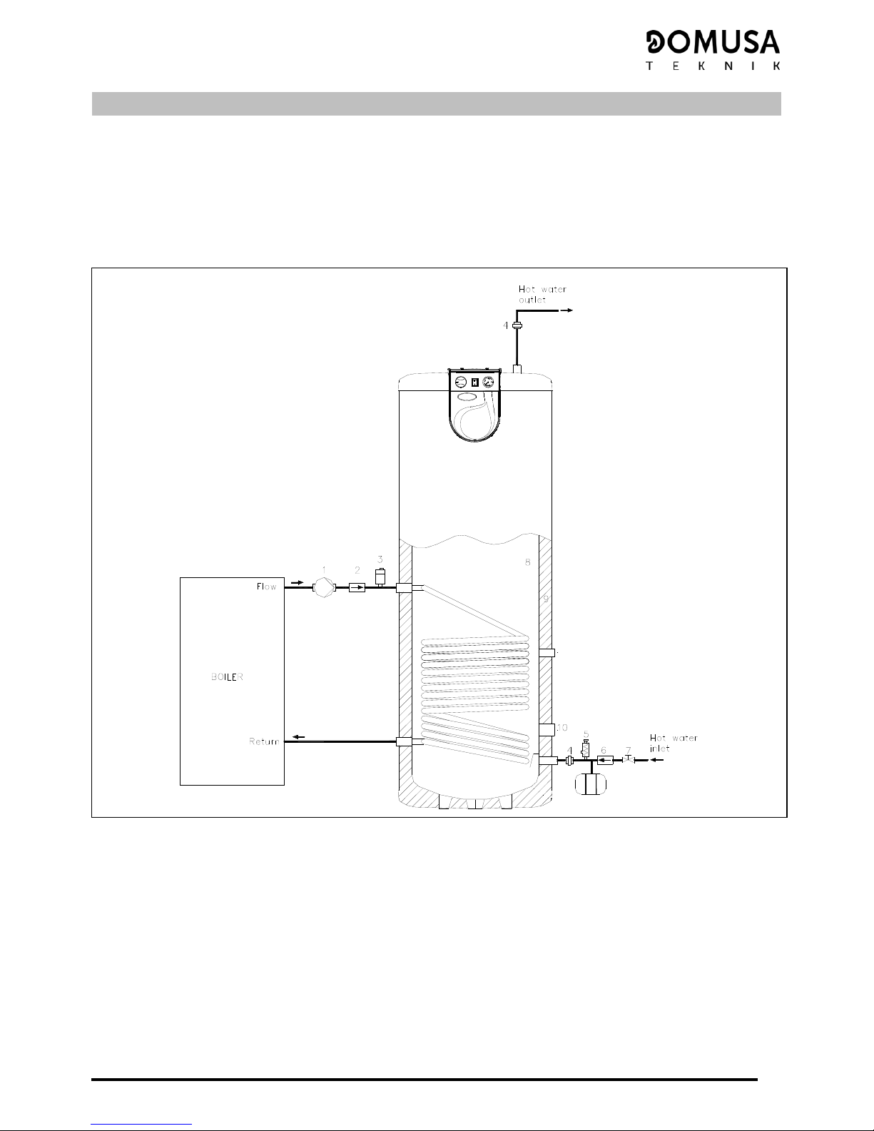
4.1 Connection
The diagram below shows an example of the installation of Sanit hot water tanks with a heating
boiler:
4.2 Equipment:
1.- Feed pump.
2.- Non-return valve.
3.- Automatic drain valve.
4.- Dielectric sleeve.
5.- 0,7 MPa (7 bar) safety valve.
6.- Non-return valve.
7.- Shut-off valve.
8.- Stainless steel hot water tank.
9.- Polyurethane insulation.
10.- Resistance socket.

Sanit
10
4.3 Hydraulic installation
Sanit hot water tanks are prepared to be permanently connected to domestic water supply
network, by means of DHW inlet. The maximum pressure admitted is specified in "Technical
characteristics" chapter.
The hydraulic installation must be made by qualified technicians, in compliance with current
installation regulations and taking the following recommendations into account:
- The secondary circuit (or domestic water circuit) is to be equipped with a safety valve,
calibrated to a maximum of 0,7 MPa (7 bar).
- The safety valve outlet must always lead to a drain.
- To avoid continuous leaking from the D.H.W. safety valve, we recommend the installation of a
D.H.W. expansion cell.
- The primary circuit (or heating circuit) for tanks must be provided with a safety valve, calibrated
to a maximum of 0,3 MPa (3 bar).
- After installing the tank, firstly fill and pressurise the secondary circuit (domestic water circuit).
- After doing so, proceed to fill the primary circuit. Ensure the secondary circuit is full before
filling the primary circuit.
- Place dielectric sleeves on the secondary circuit connections.
- If the cold water pressure is higher than the pressure the appliance is designed for, a pressure
reducer should be installed, calibrated to no higher than the design pressure.
- To prevent heat loss through the hot water pipes in accumulation systems, an anti-thermal
siphon must be installed at the hot water tank outlet. The hot water pipe must be insulated (at
least up to the anti-thermal siphon).
- A copper return circuit should not be used.
- When the chlorine concentration in the Domestic Water exceeds 250 mg/dm3, it is
recommended that anti-corrosion protection should be applied to the inside of the interaccumulator so as to avoid its premature deterioration. As an option DOMUSA TEKNIK supplies
electronic cathodic protection that is suitable for the Sanit V inter-accumulator range. To install
it, read carefully the assembly instructions that are provided with the same.
To drain the hot water tank, first drain the primary circuit and then the secondary circuit.
4.4 Location
The hot water tank must not be installed in a location exposed to the elements.
To optimise energy use, the hot water tank should be installed as close as possible to the hot water
generator.
When choosing a location, take into account the weight of the full hot water tank, and make sure it
is protected against frost. The pipes should be lagged in compliance with heating regulations.
For wall-mounted and horizontal installations, ensure the type of wall to which the hot water tank is
fixed can withstand the weight of the tank when full, and choose the most suitable fixing system
depending on the wall in question.

11
4.5 Equipment / options
Although Sanit units are equipped with all the necessary components for functioning, DOMUSA
TEKNIK offers several optional components for cases in which special features are required.
4.5.1 Cathodic protection
If the chloride concentration in the domestic
hot water is higher than 250 mg/cm3, we
recommend installing a cathodic protection
inside the storage heater to avoid premature
wear to the hot water tank. DOMUSA TEKNIK
optionally supplies a suitable electronic
cathodic protection for its range of storage
heaters. To install it, carefully read the assembly
instructions supplied with the cathodic
protection.
Figura 1
4.5.2 Electrical element
All Sanit hot water tanks have a socket for
connecting an electrical element. DOMUSA
TEKNIK optionally supplies three elements, of
1.5, 2.5 and 3.5 kW. To install them, carefully
read the assembly instructions supplied with
the elements.
Figura 2
4.5.3 18L DHW expansion tank.
Due to the increase in the temperature of the
hot water stored, the pressure in the hot water
tank increases, and DOMUSA TEKNIK therefore
optionally offers this DHW compensation tank
for the Sanit 300, 500, 750 and 1000 models. To
install the tank, carefully read the assembly
instructions supplied with it.
Figura 3

Sanit
12
4.5.4 1” dielectric sleeves
When the installation material is different from
the hot water tank socket material, a galvanic
couple may form, deteriorating the hot water
tank. To prevent this from happening,
DOMUSA TEKNIK recommends fitting
dielectric sleeves to the secondary circuit
connections if the main piping is not made of
stainless steel. To install the dielectric sleeves,
carefully read the assembly instructions
supplied with them.
Figura 4
4.5.5 DHW safety valve
All Sanit hot water tanks are designed to work
at a maximum DHW pressure of 0,7 MPa (7 bar).
To prevent this pressure from being exceeded,
DOMUSA TEKNIK recommends fitting a safety
valve to the DHW circuit, calibrated to a
maximum of 0,7 MPa (7 bar). The safety valve
will always discharge into a drain. To install the
valve, carefully read the assembly instructions
supplied with it.
Figura 5

13
5 OPERATION
The Sanit range of hot water tanks is specially designed for use with a wide range of solar power
elements, heat pumps and boilers powered by any type of fuel.
If the tank is connected to a DOMUSA TEKNIK brand heating boiler, the boiler will be equipped with a
summer or winter position switch, which is used to choose between:
- Summer position ☼: in this position the boiler will only produce hot water as needed. The burner
and feed pump of the storage heater (summer pump) will be switched on until the hot water stored
reaches the temperature set on the hot water thermostat of the storage heater
(2)
. When this
temperature is reached, the burner and the summer pump will switch off.
- Winter position : in this position the boiler will produce hot water as needed and will also cater
for the heating installation, giving priority to hot water production.
6 DIAGRAM AND ELECTRICAL CONNECTION
The Sanit range of hot water tanks is especially designed for easy electrical connection to a wide range
of heating boilers. The special design of its electrical connections enables the boiler/hot water tank
unit to provide heating and domestic hot water with automatic functioning, incorporating a hot water
priority function to the joint operation of the two appliances.
When installing the supply cable, take the hot water tank element into account. Different tanks may
have different elements, and a different cable diameter is recommended for each type:
Element Cable diameter
1500w 1.5 mm2
2500w 2.5 mm2
3500w 4 mm2
6.1 Electrical diagram
The electrical connection of Sanit hot water tank must be made by qualified staff, and any
modifications may only be made by the official technical assistance service.
7
R: Máx. 3.500 W
Orange
White
Red
Brown
Blue
Grey
Black
T
ACS
2
5
O
/
I
Blue
Black
Brown
T tube for
DHW
conection to
boiler
Ph
N
~220/230 V
1
4
21
6
5
4
3
2
1
E: Support element, maximum 3500 W.
O/I: Support element switch.
T
DHW: Domestic hot water thermostat.

Sanit
14
6.2 Electrical connection to the boiler
The electrical connection between Sanit hot water tanks and DOMUSA TEKNIK heating boilers is
made by simply connecting the tube shown in the electrical diagram, i.e. the T
DHW
tube.
Connect the tube to the side of the hot water tank as shown in the electrical diagram in section 5.1.
On the side of the boiler, connect the supply tube of the feed pump
(1)
mounted on the installation
to the terminals bearing the letters "BV" (Summer Pump) according to the electrical diagram for
each model of boiler (see the boiler instructions manual). To connect the T
DHW
tube, first remove
the bridges from the boiler connector block and then connect the T
DHW
tube as shown in the
figures below, depending on the boiler model.
6.3 Diagrams for connection to DOMUSA TEKNIK boilers:
11 1 2 3
Black
Blue
Brown
T
DHW
tube fo r
connection to
boiler
SIR ENA CAL FD
13 14 15
Black
Blue
Brown
T
DHW
tube fo r
c on ne ctio n to
boiler
DONA T E C / ECO G A S /
ECOGAS V
12 13 14 15
Black
Blue
Brown
T
DHW
tube f or
c on nec ti o n to
boiler
JAKA FD
6.4 Instructions for electrical connection of the SANIT storage heater to the following boilers:
Evolution EV FC
Evolution EV AC
Sirena Cal e
Sirena Cal V e

15
The correct process for the electrical connection of the SANIT hot water storage heater to these
boilers is as follows:
- Connect the hot water temperature sensor (supplied optionally) to the sensor connector block
J3 on the boiler (terminals 13 and 14). To do this, first remove the element (Ra) supplied with it
(see "Connection Diagram").
- Remove the thermostat bulb from the bulb-holder on the storage heater, and insert the
temperature sensor bulb in its place.
- Connect the storage heater feed pump to the boiler supply connector block J2 (terminals 6 and
7) (see the "Connection Diagram").
For a correct hydraulic installation, carefully follow the assembly and connection instructions
supplied with the storage heater.
1
356789
10
11
4
J1J2
1615141312
J3
J5
J4
NF
bc7
BC Q
Sc
TA
E20
Blue
Black
Blue
Blue
2
220 V
J6
1 2 3
RaRr
BV
Blue
M
Blue
RA
J3

Sanit
16
7 MAINTENANCE
To keep the boiler/hot water tank unit in perfect working order, both appliances should by inspected
yearly by DOMUSA TEKNIK authorised technicians. In particular, the following are recommended:
- The inside of the hot water tank should be thoroughly cleaned once a year. The primary circuit
should be drained first, before draining the hot water tank.
- If the hot water tank includes electronic cathode protection, this should be inspected once a year
to ensure it is functioning correctly.
- The pressure of the primary installation must be kept between 0.1 and 0.15 MPa (1 and 1.5 bar).
- Make sure the safety valve and the drain valve are working correctly.
- If the installation has been out of use for a long time, check the hot water tank feed pump is
working correctly. To do this, remove the front cover from the pump, leaving the pump shaft
visible. If the shaft does not turn, disconnect the pump using the pump switch. Gently press the
shaft down with a suitably sized screwdriver and turn it in both directions. Then connect the
switch again.
It is recommended for the user to periodically check the pressure and temperature levels of the hot
water tank and the state of the valves, connections and accessories.
8 START-UP
For the guarantee to be valid, the hot water tank must be started up by an Official DOMUSA TEKNIK
Technical Assistance Service. Before starting it up, the following must be ensured:
- The electrical connection of the hot water tank is correctly made.
- The installation is filled with water and the draining has been done correctly.
- The drain valve is working properly.
- The primary flow and return connections and the hot and cold water connections have been
correctly made.
- The thermostat has been properly adjusted and the electric cabling complies with regulations.
- There are no leaks from the splices and connections.
9 DELIVERY OF THE INSTALLATION
After the initial start-up of the appliance, the Technical Assistance Service will explain to the user how
the hot water tank works, making any observations they consider relevant.
It is the responsibility of the installer to explain to the user the functioning of any control devices
belonging to the installation and not supplied with the hot water tank.

17
10 DRAINING THE TANK
To drain the tank Sanit 300/500/750/1000, remove the brass plug, then connect a hose to the drain
socket on the botton of the tank.
Check the hose is correctly connected to the tank drain socket.
Run the hose to a nearby floor drain. This must be at a lower level than the tank. Begin the suction
process so that the water begins to flow, and wait until it drains completely.
SANIT 300 / 500 /750 / 1000

Sanit
18
11 SPARES LIST
11.1 Hot water tank
SANIT 300
1
2
1
2
3
5
6
7
8
9
10
11
13
12
1
2
14
15
12413
1
Pos. Code Name
1
CFER000085 ¾” black embellisher
2
CFER000082 ¾” tapered plug
3
GELESAN008 Electrical board
4
CFER000086 1” black embellisher
5
SCON000090 Elliptical plug
6
Bridge
7
M8 washer
8
M8 nut
Pos.
Code Name
9
CACU000038 Bridge cover
10
CFOL000037 Brass plug
11
MVAR010027 Seal
12
CFER000008 1” red plug
13
CFER000083 Seal
14
CFER000087 1 ¼” black embellisher
15
CFOL000020 1 ¼” chromed plug

19
SANIT 500
2
1
2
3
4
6
7
8
9
10
11
12
15
14
16
13
1
5
1
11
1
10
Pos. Código Denominación
1
CFER000086 1” black embellisher
2
CFER000081 1” tapered plug
3
GELESAN008 Electrical board
4
SCON000090 Elliptical plug
5
MVAR010027 Seal
6
Bridge
7
M8 washer
8
M8 nut
Pos.
Código Denominación
9
CACU000038 Tapa puente
10
CFER000008 1” red plug
11
CFER000083 Seal
12
CFER000087 1” ¼ black embellisher
13
CFOL000020 1 ¼” chromed plug
14
CFER000085 ¾” black embellisher
15
CFER000082 ¾” tapered plug
16
CFOL000037 Brass plug

Sanit
20
SANIT 750
1
2
3
1
2
4
5
6
7
8
10
11
12
13
16
6
9
6
7
16
1
14
15
Pos. Código Denominación
1
CFER000086 1” black embellisher
2
CFER000081 1” tapered plug
3
GELESAN008 Electrical board
4
CFER000085 ¾” black embellisher
5
CFER000082 ¾” tapered plug
6
CFER000087 1” ¼ black embellisher
7
CFER000080 1 ½” red plug
8
SCON000430 Elliptical plug
9
CFOL000020 1 ¼” chromed plug
Pos.
Código Denominación
10
Bridge
11
M8 washer
12
M8 nut
13
CACU000038 Cover bridge
14
CFOL000037 Brass plug
15
MVAR010027 Seal
16
CFER000083 Press tow

21
SANIT 1000
1
2
1
2
17
12
13
6
7
8
7
5
9
3
12
13
14
15
13
16
18
19 20 21 22 11
10 184
Pos. Código Denominación
1
CFER000081 1” tapered plug
2
CFER000086 1” tapered plug
3
SCON000090 Elliptical plug
4
MVAR010027 Seal
5
M8 washer
6
CFER000060 M8 Nut cover
7
M8 nut
8
CACU000038 Cover bridge
9
Bridge
10
CFOL000037 Brass plug
11
Lateral cover
Pos.
Código Denominación
12
CFER000080 1 ½” red plug
13
CFER000087 1” ¼ black embellisher
14
CFOL000020 1 ¼” chromed plug
15
CFER000083 Seal
16
CFER000082 ¾” tapered plug
17
GELESAN008 Electrical board
18
CFER000085 ¾” black embellisher
19
M12 Screw
20
Lateral joint
21
Lateral inox. cover
22
M12 Nut

Sanit
22
SANIT 1000 SBH
1
2
1
2
10
11
3
4
9
7
5
8
7
6
15
14
13
12
13
16
3
17
12
13
Pos. Código Denominación
1
CFER000081 1” tapered plug
2
CFER000086 1” tapered plug
3
CFER000085 ¾” black embellisher
4
SCON000090 Elliptical plug
5
M8 washer
6
CFER000060 M8 Nut cover
7
M8 nut
8
CACU000038 Cover bridge
9
Bridge
10
CFOL000037 Brass plug
Pos.
Código Denominación
11
MVAR010027 Seal
12
CFER000080 1 ½” red plug
13
CFER000087 1” ¼ black embellisher
14
CFOL000020 1 ¼” chromed plug
15
CFER000083 Seal
16
CFER000082 ¾” tapered plug
17
GELESAN008 Electrical board

23
Electrical board
4
4
2
1
3
6
7
5
Pos. Code Name
1
CELC000099 Knob
2
CELC000007 Control thermostat
3
CACU000036 Control panel cover
4
CACU000037 Control panel plug
Pos. Code Name
5
CACU000035 Control panel
6
CELC000136 Thermometer
7
CELC000025 Switch

Sanit
24
12 DIAGRAMS AND MEASUREMENTS
SS
TR
ES
R
SP
EP
SP
EP
R
SS
ES
TR
SANIT 300 SANIT 500
SANIT 750 SANIT 1000
TR
ES
SS
R
EP
SP

25
MODEL Sanit 300 Sanit 500 Sanit 750 Sanit 1000
Sanit 1000
SBH
A mm 870 914 1024 989 989
B mm 265 284 324 363 363
C mm 190 209 255 307 307
D mm 310 987 1109 1008 1008
E mm 615 589 1640 597 597
F mm --- --- 1205 1427 1427
G mm --- --- --- 483 --H mm 184 --- 255 --- --Base measurement mm
608 758 858 1058 1058
Height measurement mm 1758 1798 1941 1768 1768
Recirculation intake
R
3/4 H 3/4 H
3/4” H 3/4” H 3/4” H
Cold water inlet
ES
1" M 1" M
1-1/2" M 1-1/2" M 1-1/2" M
Hot water outlet
SS
1" M 1" M
1-1/2" M 1-1/2" M 1-1/2" M
Primary inlet / outlet
EP/SP
3/4" H 1" H
1" M 1" M 1" M
Resistance intake
TR
1-1/4" H 1-1/4" H
1-1/4" H 1-1/4" H 1-1/4" H
Drainage
V
¾” M ¾” M
¾” M ¾” M ¾” M

Sanit
26
13 TECHNICAL CHARACTERISTICS
MODEL Sanit 300 Sanit 500 Sanit 750
Sanit
1000
Sanit
1000 SBH
Characteristics
Installation Floor
Total volume L 300 500 745 1000 1000
Max. Storage temperature ºC 70 70 70 70 70
Max. working pressure of hot water
tank
MPa
bar
0.7
7
0.7
7
0.7
7
0.7
7
0.7
7
Max. primary temperature ºC 85 85 85 85 85
Max. primary working pressure
MPa
bar
0.3
3
0.3
3
0.3
3
0.3
3
0.3
3
Empty weight Kg 74 120 166 240 240
Full weight Kg 374 620 916 1240 1240
Functioning
Qp 1m3/h 1077 1370 2213 2582 2582
Qp 3m3/h 1117 1537 2481 2896 2896
Continuous flow l/h ∆30º
Qp 5m3/h 1168 1582 2555 2981 2981
Qp 1m3/h 680 1061 1619 2096 2096
Qp 3m3/h 686 1089 1664 2149 2149
Peak flow l/10min ∆30º
Qp 5m3/h 695 1097 1679 2163 2163
Qp 1m3/h 1577 2203 3463 4248 4248
Qp 3m3/h 1617 2370 3731 4562 4562
Flow up to 1hour l/h ∆30º
Qp 5m3/h 1668 2415 3805 4647 4647
Transmitted power kW Qp 1m3/h 38 48 77 86 86
Transmitted power kW Qp 3m3/h 39 54 87 97 97
Transmitted power kW Qp 5m3/h 41 55 89 101 101

27
14 GUARANTEE CONDITIONS
DOMUSA TEKNIK’s commercial guarantee
(*)
covers the regular functioning of the products
manufactured by DOMUSA TEKNIK Calefacción S.Coop. in accordance with the following conditions
and validity periods:
1. This commercial guarantee
(*)
is valid for the following periods, as from the start-up date:
2 Years for electric and hydraulic elements: pumps, valves, etc.
5 Years for domestic hot water tanks.
For a period of 2 years from the start-up date, DOMUSA TEKNIK will carry out any repairs of original
flaws or defects totally free of charge.
After these 2 years have elapsed, until the end of the guarantee period, labour costs and call-out
charges will be payable by the user.
2. The annual inspection is not included in the terms of this guarantee.
3. The start-up and annual inspection are to be carried out by personnel authorised by DOMUSA
TEKNIK.
4. The commercial guarantee
(*)
will be null and void in the following cases:
- If the annual inspection by DOMUSA TEKNIK authorised personnel has not been carried out.
- If the boiler has not been installed in accordance with the applicable laws and regulations
concerning this type of appliance.
- If the boiler has not been started up immediately after its installation, by personnel authorised by
DOMUSA TEKNIK.
Failures arising due to misuse or incorrect installation, use of unsuitable power, supply with water with
physical or chemical properties causing incrustation or corrosion, incorrect handling of the appliance
and, in general, for any reason beyond DOMUSA TEKNIK’s control, are excluded from this guarantee.
This guarantee does not affect the consumer’s rights as stipulated by law.
Note
: The start-up is included in the price of the boiler. The call-out charge is not included.
(*) Guarantee conditions valid for Spain and Portugal only.

Sanit
28
NOTES:
..............................................................................................................................................................................................................
..............................................................................................................................................................................................................
..............................................................................................................................................................................................................
..............................................................................................................................................................................................................
..............................................................................................................................................................................................................
..............................................................................................................................................................................................................
..............................................................................................................................................................................................................
..............................................................................................................................................................................................................
..............................................................................................................................................................................................................
..............................................................................................................................................................................................................
..............................................................................................................................................................................................................
..............................................................................................................................................................................................................
..............................................................................................................................................................................................................
..............................................................................................................................................................................................................
..............................................................................................................................................................................................................
..............................................................................................................................................................................................................
..............................................................................................................................................................................................................
..............................................................................................................................................................................................................
..............................................................................................................................................................................................................
..............................................................................................................................................................................................................
..............................................................................................................................................................................................................
..............................................................................................................................................................................................................
..............................................................................................................................................................................................................
..............................................................................................................................................................................................................
..............................................................................................................................................................................................................
..............................................................................................................................................................................................................
..............................................................................................................................................................................................................
..............................................................................................................................................................................................................

29
NOTES:
..............................................................................................................................................................................................................
..............................................................................................................................................................................................................
..............................................................................................................................................................................................................
..............................................................................................................................................................................................................
..............................................................................................................................................................................................................
..............................................................................................................................................................................................................
..............................................................................................................................................................................................................
..............................................................................................................................................................................................................
..............................................................................................................................................................................................................
..............................................................................................................................................................................................................
..............................................................................................................................................................................................................
..............................................................................................................................................................................................................
..............................................................................................................................................................................................................
..............................................................................................................................................................................................................
..............................................................................................................................................................................................................
..............................................................................................................................................................................................................
..............................................................................................................................................................................................................
..............................................................................................................................................................................................................
..............................................................................................................................................................................................................
..............................................................................................................................................................................................................
..............................................................................................................................................................................................................
..............................................................................................................................................................................................................
..............................................................................................................................................................................................................
..............................................................................................................................................................................................................
..............................................................................................................................................................................................................
..............................................................................................................................................................................................................
..............................................................................................................................................................................................................
..............................................................................................................................................................................................................

UK ADDRESS HEADQUARTERS & FACTORY
Unit D4 Stanlaw Abbey Business Centre, Bº San Esteban s/n
Ellesmere Port, CH65 9BF
20737 ERREZIL (Gipuzkoa)
Tel: 0151 909 6222 Tel: (+34) 943 813 899
www.domusateknik.com
DOMUSA TEKNIK reserves the right to make modifications of any kind to its product
characteristics without prior notice.
*CDOC000222*
CDOC000222 07/16
 Loading...