


OPERATION USER GUIDE
AVANTTIA
ER-0170/1996
CGM-04/392

Thank you for choosing a DOMUSA TEKNIK heating boiler. From the
range of DOMUSA TEKNIK products you have chosen the Avanttia
model. With a suitable hydraulic installation, this boiler is capable of
providing you with the temperature comfort suitable for your home, as
well as balanced and economical Domestic Hot Water (DHW)
production.
This manual forms an essential part of the product and it must be
given to the user. Read the warnings and recommendations in the
manual carefully, as they contain important information on the safety,
use and maintenance of the installation.
These boilers are to be installed by skilled personnel only, in
accordance with the legislation in force and following the
manufacturer’s instructions.
The start-up of these boilers and any maintenance operations must
only be carried out by DOMUSA TEKNIK’s Authorised Technical
Assistance Services.
The instructions shall include the substance of the following: This
appliance can be used by children aged from 8 years and above and
persons with reduced physical, sensory or mental capabilities or lack of
experience and knowledge if they have been given supervision or
instruction concerning use of the appliance in a safe way and
understand the hazards involved. Children shall not play with the
appliance. Cleaning and user maintenance shall not be made by
children without supervision.
Incorrect installation of these boilers could result in damage to people,
animals or property, and the manufacturer will hold no liability in such
cases.
DOMUSA TEKNIK informs all parties concerned that, in compliance
with section 1 of the first additional provision of Law 11/1997, the
responsibility for delivering packaging waste or used packaging for its
proper environmental management will be that of the final owner of
the product (Article 18.1 Royal Decree 782/1998). At the end of its
useful life, the product must be taken to a selected collection point for
electrical and electronic equipment or must be returned to the
distributor at the time of purchasing a new equivalent appliance. For
more detailed information on the collection schemes available, contact
either the collection facilities of the local authority or the distributor
where the purchase was made.

1
ÍNDICE Pág.
1 COMPONENTS DIAGRAM................................................................................................................................................2
2 CONTROL ELEMENTS........................................................................................................................................................4
3 DIGITAL DISPLAY................................................................................................................................................................5
3.1 OPERATION IN “STANDARD” DISPLAY MODE.....................................................................................................................................5
3.2 CHANGING THE SETTINGS....................................................................................................................................................................7
4 OPERATION...........................................................................................................................................................................8
4.1 SELECTING THE BOILER SETPONT TEMPERATURE ...............................................................................................................................9
4.2 SELECTING THE DHW SETPOINT TEMPERATURE................................................................................................................................9
4.3 SELECTING THE SETPOINT TEMPERATURE OF HEATING CIRCUIT 1..................................................................................................10
4.4 SELECTING THE SETPOINT TEMPERATURE OF HEATING CIRCUIT 2..................................................................................................10
5 ADDITIONAL FUNCTIONS............................................................................................................................................ 11
5.1 ANTILEGIONELLA FUNCTION .............................................................................................................................................................11
5.2 PUMPS ANTI-BLOCK FUNCTION.........................................................................................................................................................11
5.3 ANTI-FROST FUNCTION......................................................................................................................................................................11
5.4 BOILER PRESSURE SENSOR FUNCTION...............................................................................................................................................11
5.5 RESETTING TO FACTORY DEFAULT VALUES.......................................................................................................................................11
5.6 CONNECTING THE LAGO FB OT+ REMOTE CONTROL...................................................................................................................11
5.7 ROOM THERMOSTAT CONNECTION...................................................................................................................................................11
6 FUNCTIONING OF HEATING CIRCUIT 2 (OPTIONAL).......................................................................................... 12
7 LAGO FB OT+ REMOTE CONTROL (OPTIONAL).................................................................................................... 13
7.1 FUNCTIONING WITHOUT AN OUTDOOR SENSOR..............................................................................................................................13
7.2 FUNCTIONING WITH AN EXTERNAL SENSOR (OPTIONAL)................................................................................................................14
7.3 DHW FUNCTION................................................................................................................................................................................14
8 COMMISSIONING OF THE BOILER............................................................................................................................. 15
9 BOILER DELIVERY............................................................................................................................................................. 15
10 SHUTTING DOWN THE BOILER.................................................................................................................................15
11 DRAINING THE BOILER................................................................................................................................................15
12 SAFETY CUT-OUTS........................................................................................................................................................ 16
12.1 TEMPERATURE SAFETY CUT-OUT....................................................................................................................................................16
12.2 BURNER CUT-OUT............................................................................................................................................................................16
12.3 LOW PRESSURE CUT-OUT ................................................................................................................................................................16
13 BOILER MAINTENANCE...............................................................................................................................................17
14 ALARM CODES............................................................................................................................................................... 19
15 DIAGRAMS AND MEASUREMENTS.........................................................................................................................20
15.1 AVANTTIA HDX...............................................................................................................................................................................20
15.2 AVANTTIA HDXM...........................................................................................................................................................................21
16 TECHNICAL CHARACTERISTICS................................................................................................................................ 22
16.1 PRODUCT DATA (ACCORDING TO EC/125/2009 DIRECTIVE).....................................................................................................22
16.2 TECHNICAL DATA ............................................................................................................................................................................22
17 ELECTRICAL CONNECTION DIAGRAM...................................................................................................................24
17.1 AVANTTIA HDX...............................................................................................................................................................................24
17.2 AVANTTIA HDXM...........................................................................................................................................................................25
18 COMMERCIAL GUARANTEE.......................................................................................................................................26

Avanttia
2
1 COMPONENTS DIAGRAM
1
Avanttia HDX
9
11
3
7
8
6
2
10
4
5
1. Heat exchanger.
2. DHW expansion vessel.
3. Main primary circuit drain.
4. Heating expansion vessel.
5. DHW storage tank Inox.
6. Disconnect fill.
7. Siphon safety group.
8. Safety group.
9. Automatic boiler drain valve.
10. Main heating circuit drain.
11. Heating circuit circulation pump.

3
1
Avanttia HDXM
9
11
3
7
8
6
2
10
4
5
13
14
12
1. Heat exchanger.
2. DHW expansion vessel.
3. Main primary circuit drain.
4. Heating expansion vessel.
5. DHW storage tank Inox.
6. Disconnect fill.
7. Siphon safety group.
8. Safety group.
9. Automatic boiler drain valve.
10. Main heating circuit drain.
11. Heating circuit circulation pump.
12. Motorized 3 way valve.
13. Automatic air vent.
14. Heating mixed circuit circulation pump.

Avanttia
4
2 CONTROL ELEMENTS
16 19 2018
15
17
15. Digital display:
This is the main boiler functioning display, on
which all the operating information, settings
and values appear. This display is also used to
access the appliance’s user and service settings.
In standard operating mode (default display),
the actual boiler temperature is shown. If
malfunction occurs, an alarm code will appear
on the digital display instead of the
temperature.
16. Boiler temperature touch button:
This is used to select the boiler setpoint
temperature. It is also used to disable the hot
water function.
17. DHW temperature touch button:
This is used to select the setpoint temperature
for domestic hot water. It is also used to disable
the DHW function.
18. MODE touch button:
This button is used to access and browse the
different menus.
19. ON touch button:
This button switches the boiler on and off.
20. RESET touch button:
When the boiler is in lock-out mode, the RESET
button is pressed to reset the lock-out and
restore “Standard” functioning. If you are
modifying any of the settings or browsing the
menus, you may press the RESET button to exit
the menu WITHOUT SAVING and return to the
previous menu level.

5
3 DIGITAL DISPLAY
The Avanttia boilers are electronic and have a display
(15)
for viewing the different boiler settings. The
display has various zones where different icons and numbers appear to indicate the different statuses.
3.1 Operation in “standard” display mode
AB CFD E
A Indication of boiler status: Heating function enabled.
DHW production enabled.
B Indication of burner status: Burner functioning.
Boiler lock-out.
C Numerical display.
D Special operating icons.
Anti-frost function: This flashes when the boiler’s anti-frost function is enabled.
Servicing spanner: Steady: When any of the boiler’s technical settings on the
“Service
menu"
are being browsed or modified.
Flashing: When manual functioning of any of the outlets is forced.
E Auxiliary icons.
Steadily lit when the digits show a temperature.
bar Steadily lit when a value or setting connected with the boiler water pressure is shown.
EXT Steadily lit when a value or setting connected with the outside temperature is shown.
INT Steadily lit when a value or setting connected with the temperature inside the home or
settings connected with the LAGO FB OT+ are shown.
F Operating mode icons (see next page).
cd1 radiator: This appears on the display when the circulating pump of direct circuit 1 is
switched on (BC1 on and Sr1 not connected) or when a value or setting
connected with direct circuit 1 is shown.

Avanttia
6
cd2 radiator: This appears on the display when the circulating pump of direct circuit 2 is
switched on (BC2 on and Sr2 not connected) or when a value or setting
connected with direct circuit 2 is shown.
cm1 radiator: This appears on the display when the circulating pump of mixed circuit
1 is switched on (BC1 on and Sr1 connected) or when a value or setting
connected with mixed circuit 1 is shown. The arrows appear according
to the mixed circuit 1 mixer valve control. The upper arrow indicates
that the hot channel of the valve is open, and the lower arrow shows
that the hot channel of the valve is closed.
cm2 radiator: This appears on the display when the circulating pump of mixed circuit
1 is switched on (BC1 on and Sr1 connected) or when a value or setting
connected with mixed circuit 2 is shown. The arrows appear according
to the mixed circuit 2 mixer valve control. The upper arrow indicates
that the hot channel of the valve is open, and the lower arrow shows
that the hot channel of the valve is closed.
House: Steadily lit when a value or setting connected with the temperature inside or
outside the home or settings connected with the room thermostat or remote
controls are shown.
K curves: Steadily lit when a value or setting connected with operating in accordance
with outside weather conditions or K curves is shown.
Recirculation: Steadily: When any value or parameter related to the recirculation of DHW
is displayed or when it's ON the recirculation of DHW function (the
auxiliary input of the controller is closed.
Flashes: When the DHW recirculation pump is ON (Auxiliary boiler relay
activated).
Boiler: Steadily when viewing any value or parameter related to the gas boiler.
Hot water tank: Steadily lit when a value or setting connected with the DHW hot water
tank temperature or functioning is shown.
Browser: Steadily lit when any of the
“User Menus"
or
"Service menus”
are being
browsed.
SET Flashes when access is made to modify any of the settings.

7
3.2 Changing the settings
The boiler adjustment settings are located in the
“User Menu"
and the
“Service menu"
. To access the
“User Menu"
, press . Then press repeatedly to progress sequentially through the user settings. If
the setting shown can be modified, SET will flash on the display and the setting can be changed by
pressing the “” and “▬” symbols for DHW
(17)
and heating
(16)
.
These settings are listed in the table below:
Nº. Setting Type Range Display
1 DHW setpoint temperature Modificable
Off, 15 – 65 ºC
By default: Off
2 Actual DHW temperature Visual
3 Boiler setpoint temperature Modificable
Off, 25 – P.08
By default: Off
4 Actual boiler temperature Visual
5 Water pressure Visual
6 Boiler setpoint temperature enabled Visual
7 Setpoint flow temperature of mixed circuit 1 Modificable
Off, 10 – 45 ºC
By default: Off
8 Actual flow temperature of mixed circuit 1 Visual
9 Setpoint flow temperature of mixed circuit 2 Modificable
Off, 10 – 45 ºC
By default: Off
10 Actual flow temperature of mixed circuit 2 Visual
11 Actual outdoor temperature Visual
12 Heating demand Visual
13 Display contrast Modificable
1 – 5
By default: 3
Avanttia
8
4 OPERATION
The Avanttia boiler is designed to heat a heating installation and provide domestic hot water,
instantly and/or by collection.
Standaring functioning:
The boiler provides both heating and DHW in this mode. The burner and the circulating pump
will switch on and the diverter valve will switch to DHW mode. When the DHW storage tank
reaches the DHW setpoint temperature selected, it was ready to warm the heating installation, by
putting the diverter valve in heating mode. The burner will shut down when the boiler reaches its
selected setpoint temperature. The circulation pump will stop when the room temperature reaches
or exceeds the temperature set on the installation’s room thermostat (if it has one).
Functioning according to outdoor temperature conditions
When the boiler is connected to an outdoor temperature sensor (supplied with the boiler),
functioning may be activated according to the
outdoor temperature conditions, using parameter
P.10 on the
"Technical Menu".
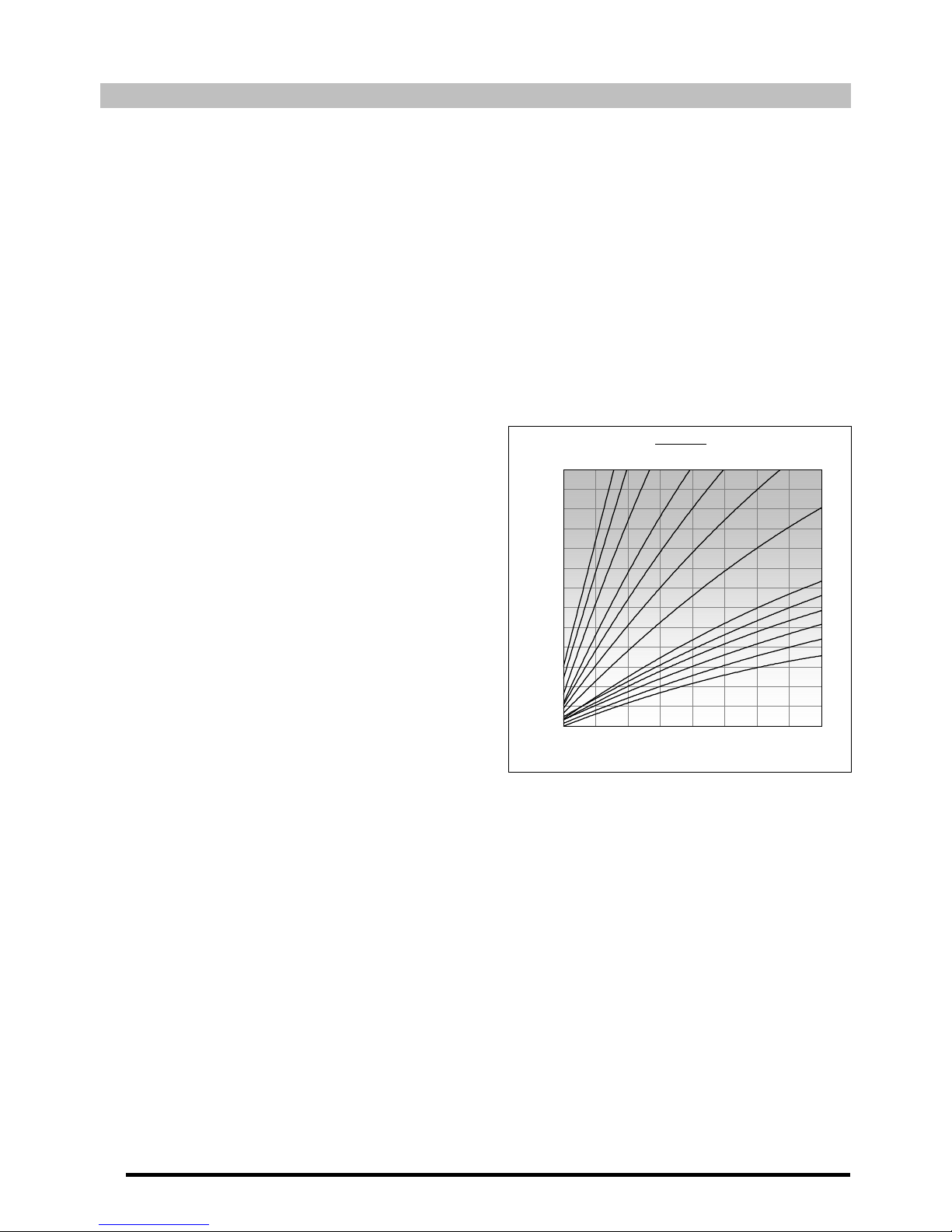
When this operating mode is activated, the boiler
and/or heating output temperature are
determined in accordance with the K curve set (for
parameter P.11 of the
"Technical Menu"
for circuit
1 and P.31 for circuit 2) and the outdoor
temperature measured. If the installation is
correctly dimensioned, the boiler temperature
and/or output temperature calculated will ensure
the room temperature is in accordance with the
set point programmed.
The K curve relates the outdoor temperature
reading on the sensor installed outside the home
to the boiler temperature setpoint. The graph
shows the temperature ratio for each point on the
K curve.
IMPORTANT: To connect the outdoor temperature sensor to the boiler, carefully follow the
connection instructions provided in the
"Electrical Connections"
section.
Disabling the heating function (Summer Mode):
In this mode, the boiler provides DHW but not heating. To disable the heating function, press the
heating “▬” symbol
(16)
until “oFF” appears on the display.
Disabling the DHW function:
In this mode the boiler provides heating but not DHW. To disable the DHW function, press the
DHW “▬” symbol
(17)
until “oFF” appears on the display. The burner, the circulation pump and the
diverter valve are in heating mode. The burner will shut down when the boiler reaches its selected
setpoint temperature. The circulation pump will stop when the room temperature reaches or
exceeds the temperature set on the installation’s room thermostat (if it has one).
K - factor
0,5
0,6
0,7
0,8
0,9
1
1,5
22,53
4
5
6
20
25
30
35
40
45
50
55
60
65
70
75
80
85
-20-15-10-505101520
Outdoor Temperature (ºC)
Boiler Temperature (ºC)

9
4.1 Selecting the boiler setpont temperature
Depending on the boiler configuration, the Heating “” and “▬” symbols
(14)
may be used to
select the desired boiler functioning temperature, as well as enabling and/or disabling the heating
function.
Providing there is a direct circuit that is not functioning according to the outside weather
conditions (P.11 = oFF and/or P.31 = oFF), or when no second heating circuit is installed, the
Heating “” and “▬” symbols
(16)
can be used to selected the desired boiler functioning
temperature, in addition to enabling and/or disabling the heating function.
The boiler setpoint temperature can also be selected by pressing until the icon appears on
the display, with the word SET flashing. The setting can be changed by pressing the Heating “”
and “▬” symbols
(16)
.
In all other cases, pressing the Heating “” and “▬” symbols
(16)
will only enable and/or disable
the heating function.
The permitted boiler setpoint temperature range is 25 - 85 ºC. Model Avanttia boilers are
condensing boilers. In order to obtain maximum boiler performance and energy savings, it is
recommended to select a setpoint temperature of 60 - 70 ºC, providing this is permitted by the
heating system installed and the insulation conditions of your home.
4.2 Selecting the DHW setpoint temperature
The desired DHW temperature can be selected by pressing the DHW “” and “▬” symbols
(17)
. If
they are not pressed for 2 seconds, the display will return to “standard” mode.
The DHW setpoint temperature can also be selected by pressing
until the icon appears on the
display, with the word SET flashing. The setting can be changed by pressing the DHW “” and “▬”
symbols
(17)
.

Avanttia
10
4.3 Selecting the setpoint temperature of heating circuit 1
The flow temperature of the circuit may be selected, providing heating circuit 1 is a mixed circuit
(heating pump of circuit 1 (BC1) and the mixer valve (M1) and sensor (Sr1)) and it is not functioning
in accordance with outside weather conditions (P.11 = oFF). To select it, press to browse until
the icon
appears on the display with the SET symbol flashing. The temperature can be
changed by pressing the Heating “” and “▬” symbols
(16).
However, if the boiler is functioning according to outside weather conditions (external EVT sensor
connected and P.10 = oN and P.11 not oFF), the circuit flow temperature cannot be selected; only
the K curve can be selected with the P.11 setting.
4.4 Selecting the setpoint temperature of heating circuit 2
The flow temperature of the circuit may be selected, providing heating circuit 2 is a mixed circuit
(heating pump of circuit 1 (BC
2
) and the mixer valve (M2) and sensor (Sr2)) and it is not functioning
in accordance with outside weather conditions (P.31 = oFF). To select it, press to browse until
the icon
appears on the display with the SET symbol flashing. The temperature can be
changed by pressing the Heating “” and “▬” symbols
(16).
However, if the boiler is functioning according to outside weather conditions (external EVT sensor
connected and P.10 = oN and P.11 not oFF), the circuit flow temperature cannot be selected; only
the K curve can be selected with the P.31 setting.
When both the boiler’s circuits are functioning with an external sensor, the Heating “” and
“▬” symbols
(16)
can only be used to enable or disable the heating function.

11
5 ADDITIONAL FUNCTIONS
The Avanttia boiler has the following additional control functions:
5.1 Antilegionella function
Using the P.17 parameter, it is possible to activate the function of protection against Legionella
bacterium. With the feature enabled, every 7 days, DHW tank temperature rises up to 65 ºC.
5.2 Pumps anti-block function
This feature prevents the boiler circulation pumps from seizing up if they have been out of use for a
long period. This system remains enabled while the boiler is plugged into the mains.
5.3 Anti-frost function
This function protects the boiler from freezing up during cold weather. If the boiler temperature
drops to below 6 ºC, the heating circulation pump will start up. If the boiler temperature continues
to drop and reaches 4 ºC, the burner will start up, heating the installation. When this function has
been activated, it will continue working until the boiler reaches 8 ºC. This system remains on
standby while the boiler is plugged into the mains.
5.4 Boiler pressure sensor function
This function prevents boiler failure caused by a low water level and excess pressure in the boiler.
The pressure is detected by a pressure sensor, and its value appears on the control panel display
(on the
“User Menu”
). If the pressure drops below 0.05 MPa (0.5 bar), the electronic control switches
off the boiler and triggers an alarm on the display ("E02"). When the boiler pressure exceeds 0.25
MPa (2.5 bar), an alarm is triggered on the display ("HI") to warn of the excess pressure. If this should
occur, we recommend calling the nearest Technical Assistance Service, and draining the boiler
until the pressure is between 0.1 and 0.15 MPa (1 and 1.5 bar).
5.5 Resetting to factory default values
If these settings are wrongly adjusted or if the boiler functions incorrectly, all the original settings of
all the parameters can be restored by selecting oH in parameter P.26.
5.6 Connecting the LAGO FB OT+ remote control
The boiler has a terminal strip, J5, for connecting the LAGO FB OT+ remote control (see
"Connection Diagram”
). This allows the heating mode for circuit 1 to be switched off, according to
the room temperature.
Installing the LAFO FB OT+ remote control enables the heating and DHW system to adapt to the
scheduled times for use of the installation. It also optimises the installation’s functioning, adapting
the heating setpoint temperature to the room temperature and improving comfort.
5.7 Room thermostat connection
The boiler has two terminal strips, J4 and J6, for connecting room thermostats or room
chronothermostats (TA1 and TA2, see "Electrical Connection Diagram”). This allows the heating
mode for each circuit installed to be switched off according to the room temperature. To connect it,
remove the bridge joining the terminals of each terminal strip, J4 and J6, and connect room
thermostat Nº 1 or Nº 2 for circuits 1 or 2 respectively.
Installing a room thermostat will optimise the performance of the installation, adapting the heating
to your home’s requirements and obtaining enhanced comfort. Also, if the thermostat allows the
hours of functioning to be programmed (chronothermostat), it can adapt the heating system to the
hours of use of the installation.

Avanttia
12
6 FUNCTIONING OF HEATING CIRCUIT 2 (OPTIONAL)
All the boiler models in the Avanttia range may optionally control a second heating circuit. For this
second circuit to be controlled, a second circulating pump (BC2) needs to be installed on the boiler if a
direct circuit is required, or a pump (BC2) and a mixer valve (M2) if a mixed circuit is required. For
correct installation, carefully follow the instructions given in the
“Installation with two heating circuits”
section of this manual.
Direct circuit functioning
Heating circuit 2 will work with the selected boiler setpoint temperature and the temperature of
room thermostat 2 (TA2) (if the boiler has one). When circuit 2 is functioning with an external
sensor (P.10 = ON and P.31 not OFF), the boiler temperature will depend on the outside
temperature and the curve selected in setting P.31.
Mixed circuit functioning
Heating circuit 2 will work with the selected setpoint flow temperature for mixed circuit 2 and the
temperature of room thermostat 2 (TA2) (if the boiler has one). When circuit 2 is functioning with
an external sensor (P.10 = ON and P.31 not OFF), the setpoint flow temperature will depend on the
outside temperature and the curve selected in setting P.31.
In both cases, the burner, the heating pump of circuit 2 (BC2) and the mixer valve (M2) (if the
installation has one) will begin to function until the selected temperature is reached in the installation
or on room thermostat 2 (if the installation has one). When the temperature of the installation drops
below the selected boiler temperature, the burner will start up again, running the heating cycle.

13
7 LAGO FB OT+ REMOTE CONTROL (OPTIONAL)
A remote control (LAGO FB OT+) can optionally be supplied together with the Avanttia boiler. This
remote control can be used to fully operate the boiler from anywhere in the room in which it is
installed. The LAGO FB OT+ remote control governs the parameters of heating circuit Nº 1 and the
installation’s domestic hot water production.
This remote control allows the hours of home comfort to be programmed for heating circuit Nº 1,
adjusting the installation to the particular requirements of the home by measuring the room
temperature and consequently adapting the installation temperature. The remote control can also be
used to adjust the hot water and heating set point temperatures at any time, and for viewing the
different boiler operation parameters. It also warns of any functioning anomalies affecting the boiler.
The LAGO FB OT+ remote control may optionally be connected to an external sensor, for measuring
the outside temperature. With this option installed, the remote control can adjust the home comfort
level (circuit Nº 1) according to the weather conditions at each particular time, optimising fuel
consumption and heating comfort in the home.
The LAGO FB OT+ remote control takes over the control of the boiler when it is connected to it. The
different selectable boiler temperatures must be modified using the remote control. It is easy to install,
only requiring 2 wires for communication between the boiler and the LAGO FB OT+ control. It is
connected to the boiler by connecting the two wires on terminal strip J6 (see “Electrical Connection
Diagram”). For correct installation and functioning, carefully read the instructions enclosed with the
remote control.
The following sections contain a general explanation of the different operating modes and options of
the LAGO FB OT+ remote control.
NOTE: The "AF outdoor temperature sensor" indicated in the instructions manual of remote
controller is not compatible with the boiler, so it is compulsory the use of "EVT outdoor
sensor" (provided within the boiler) to measure the outdoor temperature.
7.1 Functioning without an outdoor sensor
Conventional heating installation (direct circuit)
The maximum temperature for heating circuit Nº 1, the heating times and the desired room
temperatures can be selected on the remote control. The LAGO FB OT+ remote control will
calculate the boiler temperature required at each particular time, depending on the temperature
of the room, and it will activate or disable the heating mode of circuit Nº 1 depending on the
heating times and room temperatures programmed.
Instalation of heating circuit Nº 2 (optional)
If the boiler is supplied with an second heating circuit, this circuit is adjusted and controlled via
the boiler control panel (see
"Functioning of heating circuit Nº 2 (optional)"
).

Avanttia
14
7.2 Functioning with an external sensor (Optional)
If the LAGO FB OT+ remote control is fitted with an outdoor temperature sensor, it can calculate the
heating temperature of heating installation Nº 1 according with the outside weather conditions at
each particular time, with optimum adjustment of the heating installation conditions for improved
heating comfort in the home and energy savings.
The maximum temperature and an operating curve for heating circuit Nº 1, the heating times and
the room temperatures desired can all be selected on the remote control (see instructions enclosed
with the LAGO FB OT+ remote control). The LAGO FB OT+ remote control calculates the required
boiler temperature at each particular time, depending on the temperature inside the home and the
outside weather conditions, in accordance with the operating curve selected (parameter 01 on the
“User Menu"
of the LAGO FB OT+), switching the heating on and off in accordance with the heating
times and the room temperatures programmed.
Depending on the type of heating circuit, the following adjustments should be made:
Conventional heating installation (direct circuit)
In setting 01 of the LAGO FB OT+
“User Menu"
, select a curve of at least 1. The maximum boiler
temperature can also be selected on the LAGO FB OT+ remote control.
Installing low temperature heating (mixed circuit)
In setting 01 of the LAGO FB OT+
“User Menu”
, select a curve of less than 0.8. We also
recommend selecting a maximum flow temperature NO HIGHER THAN 85ºC, to protect the
underfloor heating installation from overheating. To do this, select the maximum flow
temperature of heating circuit 1 in setting 07 of the LAGO FB OT+
“Service Menu”
.
0,2
0,4
0,6
0,8
1
1,2
1,5
20
25
30
35
40
45
50
55
60
65
70
75
80
85
20161284 0-4-8-12-16
Outdoor Tempera ture (ºC)
Boiler Temperature (ºC)
K Curves
NOTE: The "AF outdoor temperature sensor" indicated in the instructions manual of remote
controller is not compatible with the boiler, so it is compulsory the use of "EVT outdoor
sensor" (provided within the boiler) to measure the outdoor temperature.
7.3 DHW function
When the remote control is connected to an Avanttia boiler, the desired DHW temperature and the
desired hours for DHW use can be selected on the LAGO FB OT+ remote control. The LAGO FB OT+
remote control regulates the DHW tank temperature at each particular time, and enables or
disables the DHW function according to the times scheduled.

15
8 COMMISSIONING OF THE BOILER
The start-up of the boiler, for the validity of warranty to be in force, is to be carried out by an
authorised Technical Assistance Service. Prior to proceeding to such a start-up, the following steps
will be performed:
- Check that the boiler is properly connected to the electric power supply.
- Check that the installation is filled with water (the pressure gauge must indicate a pressure
between 0.1 and 0.15 MPa (1 and 1.5 bar)).
- Check for the proper chimney installation.
- Check that the gas supply connection is properly installed.
- Drain the air off the boiler gas circuit by opening the shutoff valve of the gas line and loosening
lightly the valve gas intake pressure tapping for a moment as, otherwise, the air would be forced
to come out slowly through the pilot burner injector.
- Check that the heating circuits outlet and return flow valves are opened, if any.
- Turn the chronothermostat or LAGO FB OT+ remote control (if these are fitted) to the desired
setting.
- It is compulsory to do a combustion analysis in the boiler, using a proper tester. The combustion
test will be done through the hole for this purpose, placed in the plastic pipe of combustion
products exhaustion inside the boiler. If test is out of margins described in the section
"Combustion adjustment", it will be necessary to adjust the combustion.
To start up the boiler, hold down the button, select the desired setpoint temperatures and turn
the chronothermostat or LAGO FB OT+ remote control (if these are fitted) to the desired setting.
9 BOILER DELIVERY
The Technical Assistance Service, once the commissioning of the boiler has been carried out, will
explain the boiler operation to the users by informing them about the most necessary remarks.
The installer will be responsible for explaining to the users the operation of any control or regulation
device that is a part of the installation and it is not supplied with the boiler.
10 SHUTTING DOWN THE BOILER
To switch off the boiler, hold down the button. In Off mode, while the boiler is plugged into the
mains and connected to the fuel installation, its heating and hot water functions will be switched off
but the anti-frost protection and pump anti-block functions will remain activated.
To shut down the boiler functioning completely, unplug it from the mains and cut off the fuel supply.
11 DRAINING THE BOILER
The water is drained from the boiler by opening the air drain valve
(10)
, located inside the boiler on
the lower left hand side of the heat exchanger. Connect a flexible tube to this valve and run it to a
drain. After draining the boiler, close the valve again and remove the flexible tube.

Avanttia
16
12 SAFETY CUT-OUTS
The boiler’s electronic control system may activate the following safety cut-outs to stop the boiler
functioning. When one of these safety cut-outs occurs, the boiler will stop functioning, a cut-out code
will flash on the display and the red alarm warning pilot light will flash on the control panel.
If any of the safety cut-outs described below should occur repeatedly, switch off the boiler and
call your nearest official technical assistance service.
12.1 Temperature safety cut-out
When this cut-out occurs, the "E30" code (temperature alarm) will begin to flash on the digital
display and the alarm warning pilot light will flash on the control panel. The burner will switch off
and stop heating the installation.
This occurs when the boiler exceeds a temperature of 110 ºC. To unblock it, wait until the boiler
drops to below 100 ºC and press the button .
12.2 Burner cut-out
When this cut-out occurs, the code “E09” will begin to flash on the digital display and the flame
failure symbol. The burner will switch off and stop heating the installation.
This occurs as a result of an anomaly in the burner or in the fuel installation. To unblock it, press the
button
.
12.3 Low pressure cut-out
When this cut-out occurs, the code “E02” will begin to flash on the digital display and the flame
failure symbol. The burner amd the boiler circulation pumps will switch off, cutting off the heating
and water flow to the installation.
This occurs when the boiler pressure drops to below 0.05 MPa (0.5 bar), preventing the boiler from
functioning when the water is drained from the installation, due to either leakage or maintenance
operations. To unlock it, press the button
.

17
13 BOILER MAINTENANCE
To maintain the boiler in perfect working order, a yearly overhaul is to be performed by DOMUSA
TEKNIK’s authorised personnel.
Boiler and flue maintenance
The most important aspects to be checked are as follows:
- The water pressure in the heating installation, when the water is cold, must be between 0.1
and 0.15 MPa (1 and 1.5 bar). If it is not between these values, it must be filled until they are
reached.
- The control and safety devices (thermostats, gas valve, etc.) must function correctly.
- The burner and the inside of the boiler chamber must be clean. Soft brushes or compressed air
are recommended for cleaning the boiler, to prevent damage. Do not use chemical products.
- The expansion vessel must be full, in accordance with the specifications on the vessel plate.
- Check the gas and water installations are completely sealed.
- The flues must be free of any obstacles and have no leaks.
- The gas flow must remain between the values indicated on the
Specifications Sheet
.
- The circulating pumps and mixer valves (if the boiler is equipped with these) must not be
blocked.
Cleaning the boiler
The boiler does not require any special maintenance. Yearly cleaning at the end of the heating
season will be sufficient. The boiler chamber and burner should not be cleaned using chemical
products or steel brushes. After any cleaning operation has been carried out, it is important to
ensure that several ignition cycles are performed to check all the elements are functioning
correctly.
After checking the boiler is functioning correctly, ensure there are no leaks.
Draining the condensation water
The boiler condensation water drain outlet should not be altered in any way and it must be kept
free of obstructions. Yearly cleaning of the condensation collection siphon is recommended.
If a neutralisation system is installed at the condensation drain outlet, it should undergo periodical
maintenance, in accordance with the manufacturer’s instructions.
Cleaning products
Never use chemical products to clean the boiler. A plastic brush is sufficient, if the cleaning is
carried out annually.
The cleaning of the boiler and hydraulic circuit will have lasting effects if water with a hardness of
over 25ºF is treated previously. For softer water no treatment is required. In any case, a descaling
pump should be used to carry out the descaling process.

Avanttia
18
Anti-frost precautions
The Avanttia boiler, have a function to prevent the installation from freezing, ensuring that the
boiler is connected to the electrical power supply. In any case, and mainly in geographical zones
where very low temperatures are usual, it is advisable to add anti-freezing liquid to heating circuit.
When a very long period the boiler is not going to work, it is advisable to empty the boiler totally.
Boiler water characteristics
In case of water hardness of over 25-30ºF, we recommend using treated water in the heating
installation to avoid any scale deposits on the boiler.
Bear in mind that a scale deposit of even a few millimetres will cause a major reduction in boiler
performance, as scale is a poor thermal conductor.
It is essential to treat the water used in the heating circuit in the following cases:
- Very long circuits (containing a large amount of water).
- Frequent filling of the installation.
If repeated partial or total draining of the installation is necessary, we recommend filling it with
treated water.

19
14 ALARM CODES
The Avanttia boiler has an electronic circuit which performs continuous self-testing to detect any
malfunctioning in the boiler. When the electronic control detects malfunctioning, this is indicated by
an alarm code flashing on the display. The following list describes the alarm codes that may appear:
Cod. Cause Action required
E02 Low water pressure If it occurs repeatedly, call the TAS.
E03 Ignition failure Reset the boiler.
E04 Flame simulation Call the TAS.
E05 Boiler temperature sensor: open Call the TAS.
E06 Boiler temperature sensor: shorted Call the TAS.
E07 N/A: Wrong boiler model selected Call the TAS.
E08 N/A: Wrong boiler model selected Call the TAS.
E09 Fan anomaly Reset the boiler.
E10 Air pressure anomaly Reset the boiler.
E11 Water pressure sensor failure Call the TAS.
E12 Flame extinguished Reset the boiler.
E15 BMC anomaly Reset the boiler.
E16 Heat exchanger overheating Reset the boiler.
E17 Switch selection error Reset the boiler.
E18 Return temperature sensor: open Call the TAS.
E19 Return temperature sensor: shorted Call the TAS.
E21 DHW tank temperature sensor: open Call the TAS.
E22 DHW tank temperature sensor: shorted Call the TAS.
E27 Air pressure sensor anomaly Reset the boiler.
E28 Water leak Call the TAS.
E30 Fume outlet overheating Reset the boiler.
E40 Outdoor temperature sensor: shorted Call the TAS.
E41 Outdoor temperature sensor: open Call the TAS.
E62 External safety system Call the TAS.
E64 Safety valve anomaly Call the TAS.
E65 External pump anomaly Reset the boiler.
E82 Boiler communication failure Call the TAS.
E93 Abnormal functioning of panel buttons Call the TAS.
A01 Sr1 sensor: open circuit or shorted Call the TAS.
A02 Sr2 sensor: open circuit or shorted Call the TAS.
A03 Si sensor: open circuit or shorted Call the TAS.
A05 Wrong button held down on control panel Call the TAS.
A06 Boiler model configuration error Call the TAS.
A07 NCN control communication error Call the TAS.
CnF Wrong micro switch configuration Call the TAS.
NOTA: It will be very useful for the technical assistance service if you can inform them of the
alarm code that has appeared on call-out.

Avanttia
20
15 DIAGRAMS AND MEASUREMENTS
15.1 Avanttia HDX
1690
1667
1008866
PR
ES
VSES
EG
RC
IC
SS
VC
VSC
VD
B
A
C
920
910
E
D120
559
286436
720
1690
1667
1008866
PR
ES
VSES
EG
RC
IC
SS
VC
VSC
VD
B
A
C
920
910
E
D120
559
286436
720
EA
Connection
Avanttia
25 HDX
Avanttia
37 HDX
IC: Heating output.
3/4" M
A
665 765
RC: Heating return.
3/4" M
B
780 880
EG: Gas inlet.
3/4" M
C
850 950
ES: DCW inlet.
3/4" M
D
560 660
SS: DHW outlet.
3/4" M
E
730 830
PR: Recirculation outlet.
1/2" M
VSES: DHW safety valve.
-
VD: Disconnect exit.
-
VSC: Heating safety valve.
-
VC: Condensate drain.
-
EA: Gas removal / Air intake.
Ø60-100

21
15.2 Avanttia HDXM
286436
720
1690
1667
C
7165
86
PR
ES
VSES
EG
IC
SS
VC
VSC
VD
RC
ICM
RCM
A
B
910
1090
1150
1210
E
120
D
910 180
EA
Connection
Avanttia 25
HDXM
Avanttia 37
HDXM
ICO: Heating output optional circuit.
3/4" M
A
665 765
RCO: Heating return optional circuit.
3/4" M
B
780 880
ICM: Heating output mixed circuit
3/4" M
C
850 950
RCM: Heating return mixed circuit.
3/4" M
D
560 660
EG: Gas inlet.
3/4" M
E
730 830
ES: DCW inlet.
3/4" M
SS: DHW outlet.
3/4" M
PR: Recirculation outlet.
1/2" M
VSES: DHW safety valve.
-
VD: Disconnect exit.
-
VSC: Heating safety valve.
-
VC: Condensate drain.
-
EA: Gas removal / Air intake.
Ø60-100

Avanttia
22
16 TECHNICAL CHARACTERISTICS
16.1 Product data (according to EC/125/2009 Directive)
AVANTTIA
25 HDX
25 HDXM
37 HDX
37 HDXM
-
Condensation
Boiler type
-
Heating and instantaneous hot
water production
Rated heat output P
rated
kW 24 35
Useful heat output P4 kW 23,1 34,2
Useful heat output (30%) P1 kW 5,2 7,5
Seasonal space heating energy efficiency
Ƞ
S
% 91 92
% (PCI) 98 98
Useful efficiency
Ƞ
4
% (PCS) 88,3 88,3
% (PCI) 108,3 108,2
Useful efficiency (30%)
Ƞ
1
% (PCS) 97,6 97,5
Auxiliary electricity consumption at full load el
max
kW 0,110 0,110
Auxiliary electricity consumption at part load el
min
kW 0,042 0,042
Auxiliary electricity consumption in standby mode PSB kW 0,043 0,043
Standby heat loss P
stby
kW 0,043 0,043
Emissions of nitrogen oxides NOx mg/kWh 37 41
Declared load profile - XL XL
Water heating energy efficiency
Ƞ
wh
% 81 80
Daily electricity consumption Q
elec
kWh 0,220 0,210
Daily fuel consumption Q
fuel
kWh 25,102 25,899
16.2 Technical Data
AVANTTIA
Specifications
25
HDX / HDXM
37
HDX / HDXM
Heating consumption (Max/Min) kW 23,5 / 4,9 34,9 / 7,0
DHW heat consumption (Max/Min) kW 23,5 / 4,9 34,9 / 7,0
Heating output (Max/Min) at 80/60 ºC kW 23,1 / 4,8 34,2 / 6,8
DHW output (Max/Min) kW 23,1 / 4,8 34,2 / 6,8
Condensing heating output (Max/Min) at 50/30 ºC kW 25,2 / 5,2 37,6 / 7,5
Full load efficiency at Max/Min output, at 80/60 ºC % 98,1 / 97,4 98,0 / 97,6
Full load efficiency at Max/Min output, at 50/30ºC (condensation) % 107,2 / 106,9 107,7 / 106,9
Partial load (30%) efficiency, with 47 ºC return temperature % 101,6 101,9
Partial load (30%) efficiency, with 30 ºC return temperature % 108,4 108,3
Heat Loss through the case with burner switched on % 0,1 0,1
Heat Loss through the chimney with burner switched on % 1,8 1,9
Seasonal efficiency rate (SEDBUK rating) - A
NOx class - 5
Category - II2H3P
Heating output adjustment -
Adjustable over entire Max/Min output
range
Type of heating installation - Close circuit
Maximum heating pressure MPa 0,3 (3 bar)

23
AVANTTIA
Specifications
25
HDX / HDXM
37
HDX / HDXM
Maximum heating temperature ºC 110
Adjustable heating temperature range ºC 25 - 85
Expansion heating vessel volume l 7,5 12
Expansion heating vessel pre-load MPa 0,1 (1 bar)
Expansion DHW vessel volume l 8
Expansion DHW vessel pre-load MPa 0,3 (3 bar)
Minimum DHW pressure MPa 0,7 (7 bar)
Adjustable tank DHW temperature range ºC 15 – 65
Capacity of storage tank L 100 130
D.H.W. production in 10 min. ∆T = 30 ºC
L 245 359
D.H.W. production in 1 hour. ∆T = 30 ºC
L 830 1240
Electrical supply - 230 V~ / 50 Hz
Electrical maximum consumption (HDX/HDXM) W 315 / 415
Electrical protection - IP X5D
Boiler mounting system type - Standing
Flue exhaust/Air intake system types - B23-B33-B53-C13-C33-C43-C53-C63-C83
Flue exhaust/Air intake system diameters mm
Coaxial Ø60/100 and Ø80/125 – Dual duct
Ø80/80
Maximum gas pipe pressure drop Pa 167 167
Flue gas temperature ºC 63 63
Maximum flow of fumes g/s 10,2 10,2
Max. horizontal coaxial length Ø60/100 m 20
Max. vertical coaxial length Ø60/100 m 21
Equivalent elbow length at 90º Ø60/100 m 1,3
Equivalent elbow length at 45º Ø60/100 m 1
Max. horizontal coaxial length Ø80/125 m 68
Max. vertical coaxial length Ø80/125 m 70
Equivalent elbow length at 90º Ø80/125 m 2,2
Equivalent elbow length at 45º Ø80/125 m 1
Equivalent length of adapter Ø60/100 => Ø80/125 m 0,5
Max. dual duct length Ø80-Ø80 m 110
Equivalent elbow length at 90º Ø80 m 2,2
Equivalent elbow length at 45º Ø80 m 1,4
Heating
3/4 3/4
DHW
1/2 1/2
Hydraulic connection
diameter
Gas inlet
3/4 3/4
Dimensions (Width x Depth x Height) mm 559 x 720 x 1690 559 x 720x 1690
Weight Kg 180 / 191 195 / 202

Avanttia
24
17 ELECTRICAL CONNECTION DIAGRAM
There are a series of removable terminal strips located on the rear of the control panel, for connecting
the various options and components of this model. To connect them correctly, carefully follow the
indications shown below:
17.1 Avanttia HDX
1
976
5
NNN
N
8
J1
J2
16
151413
J3
NF
J4
TA1
2
230 V~
J6
TA
2
10 11
43
17 18 19
Rr
1
Rr
2
R
12
J5
Lago FB
7
6
5
4
3
2
1
J7
NC
NO
C
T
aux
S
ext
BC
1
M
1
BC
2
M
2
+
-
+
-
F: Phase.
N: Neutral.
BC1: Heating circuit N. 1 circulating pump.
BC2: Heating circuit N. 2 circulating pump.
M1: Underfloor 3 way valve motor circuit 1.
M2: Underfloor 3 way valve motor circuit 2.
TA1: Heating circuit N. 1 room thermostat.
TA2: Heating circuit N. 2 room thermostat.
Rr1: Underfloor circuit N.1 option resitance.
Rr
2
: Underfloor circuit N.2 option resitance.
Raux: Auxiliary relay.
R: Phone relay.
C: Common of auxiliary relay.
NO: Normaly open of auxiliary relay.
NC: Normaly closed of auxiliary relay.
Sext: Exterior room sensor.
Taux: Auxiliary entrance.
J1: Power supply connector
J2: Components connector.
J3: Sensor connector.
J4: Room thermostat N. 1 connector.
J5: Remote control connector.
J6: Room thermostat N. 2 connector.
J7: Principal connector (Orange).

25
17.2 Avanttia HDXM
1
976
5
NNN
N
8
J1
J2
16
151413
J3
NF
J4
TA1
2
230 V~
J6
TA
2
10 11
43
17 18 19
S
r
1
12
J5
Lago FB
Rr
2
R
7
6
5
4
3
2
1
J7
NC
NO
C
T
aux
S
ext
M
1
M
2
+
-
+
-
F: Phase.
N: Neutral.
BC1: Heating circuit N. 1 circulating pump.
BC2: Heating circuit N. 2 circulating pump.
M1: Underfloor 3 way valve motor circuit 1.
M2: Underfloor 3 way valve motor circuit 2.
TA1: Heating circuit N. 1 room thermostat.
TA2: Heating circuit N. 2 room thermostat.
Sr1: Heating circuit mixed 1 sensor.
Rr2: Underfloor circuit N.2 option resitance.
Raux: Auxiliary relay.
R: Phone relay.
C: Common of auxiliary relay.
NO: Normaly open of auxiliary relay.
NC: Normaly closed of auxiliary relay.
Sext: Exterior room sensor.
Taux: Auxiliary entrance.
J1: Power supply connector.
J2: Components connector.
J3: Sensor connector.
J4: Room thermostat N. 1 connector.
J5: Remote control connector.
J6: Room thermostat N. 2 connector.
J7: Principal connector (Orange).

Avanttia
26
18 COMMERCIAL GUARANTEE
DOMUSA TEKNIK’s commercial guarantee(*) covers the standard functioning of the products
manufactured by DOMUSA TEKNIK Calefacción S.Coop., in accordance with the following conditions
and time periods:
1. This commercial guarantee is valid for the following periods, as from the start-up date:
2 Years for electric and hydraulic elements: pumps, valves, etc.
5 Years for heat exchangers.
5 Years for domestic hot water tanks.
During the 2-year period following the start-up date, DOMUSA TEKNIK will carry out any repairs of
original flaws or defects totally free of charge.
After these 2 years have elapsed and until the end of the guarantee period, labour costs and callout charges will be payable by the user.
2. The annual overhaul is not included in the terms of this guarantee.
3. The start-up and annual overhaul are to be carried out by personnel authorised by DOMUSA
TEKNIK.
4. The commercial guarantee will be null and void in the following cases:
- If the annual overhaul by personnel authorised by DOMUSA TEKNIK has not been carried out.
- La caldera no haya sido instalada respetando las leyes y reglamentos vigentes en la materia.
- If the boiler has not been installed in accordance with the applicable laws and regulations for this
type of appliance.
- If the boiler has not been started up immediately after its installation, by personnel authorised by
DOMUSA TEKNIK.
Failures due to misuse or incorrect installation, use of non-suitable electrical power or fuel, supply with
water with physical or chemical properties causing incrustation or corrosion, incorrect handling of the
appliance and, in general, for any reason beyond DOMUSA TEKNIK’s control, are excluded from this
guarantee.
This guarantee does not affect the consumer’s rights as stipulated by law.
Note: Start-up is included in the price of the boiler. The call-out charge is not included.

27
NOTES:
..............................................................................................................................................................................................................
..............................................................................................................................................................................................................
..............................................................................................................................................................................................................
..............................................................................................................................................................................................................
..............................................................................................................................................................................................................
..............................................................................................................................................................................................................
..............................................................................................................................................................................................................
..............................................................................................................................................................................................................
..............................................................................................................................................................................................................
..............................................................................................................................................................................................................
..............................................................................................................................................................................................................
..............................................................................................................................................................................................................
..............................................................................................................................................................................................................
..............................................................................................................................................................................................................
..............................................................................................................................................................................................................
..............................................................................................................................................................................................................
..............................................................................................................................................................................................................
..............................................................................................................................................................................................................
..............................................................................................................................................................................................................
..............................................................................................................................................................................................................
..............................................................................................................................................................................................................
..............................................................................................................................................................................................................
..............................................................................................................................................................................................................
..............................................................................................................................................................................................................
..............................................................................................................................................................................................................
..............................................................................................................................................................................................................
..............................................................................................................................................................................................................
..............................................................................................................................................................................................................

Avanttia
28
NOTES:
..............................................................................................................................................................................................................
..............................................................................................................................................................................................................
..............................................................................................................................................................................................................
..............................................................................................................................................................................................................
..............................................................................................................................................................................................................
..............................................................................................................................................................................................................
..............................................................................................................................................................................................................
..............................................................................................................................................................................................................
..............................................................................................................................................................................................................
..............................................................................................................................................................................................................
..............................................................................................................................................................................................................
..............................................................................................................................................................................................................
..............................................................................................................................................................................................................
..............................................................................................................................................................................................................
..............................................................................................................................................................................................................
..............................................................................................................................................................................................................
..............................................................................................................................................................................................................
..............................................................................................................................................................................................................
..............................................................................................................................................................................................................
..............................................................................................................................................................................................................
..............................................................................................................................................................................................................
..............................................................................................................................................................................................................
..............................................................................................................................................................................................................
..............................................................................................................................................................................................................
..............................................................................................................................................................................................................
..............................................................................................................................................................................................................
..............................................................................................................................................................................................................
..............................................................................................................................................................................................................

29
NOTES:
..............................................................................................................................................................................................................
..............................................................................................................................................................................................................
..............................................................................................................................................................................................................
..............................................................................................................................................................................................................
..............................................................................................................................................................................................................
..............................................................................................................................................................................................................
..............................................................................................................................................................................................................
..............................................................................................................................................................................................................
..............................................................................................................................................................................................................
..............................................................................................................................................................................................................
..............................................................................................................................................................................................................
..............................................................................................................................................................................................................
..............................................................................................................................................................................................................
..............................................................................................................................................................................................................
..............................................................................................................................................................................................................
..............................................................................................................................................................................................................
..............................................................................................................................................................................................................
..............................................................................................................................................................................................................
..............................................................................................................................................................................................................
..............................................................................................................................................................................................................
..............................................................................................................................................................................................................
..............................................................................................................................................................................................................
..............................................................................................................................................................................................................
..............................................................................................................................................................................................................
..............................................................................................................................................................................................................
..............................................................................................................................................................................................................
..............................................................................................................................................................................................................
..............................................................................................................................................................................................................

UK ADDRESS HEADQUARTERS & FACTORY
Unit D4 Stanlaw Abbey Business Centre, Bº San Esteban s/n
Ellesmere Port, CH65 9BF
20737 RÉGIL (Guipúzcoa)
Tel: 0151 909 6222 Tel: (+34) 943 813 899
www.domusateknik.com
DOMUSA TEKNIK reserves the right to make modifications of any kind to its product
characteristics without prior notice.
*CDOC001264*
CDOC001264 06/16
 Loading...