

Page 1
Resource Identifier 100217
Revision: 8.0
SOL8SDR Hardware Guide
Commercial in Confidence
DTC – Solent
Fusion 2
1100 Parkway
Solent Business Park
Whiteley
Hampshire
PO15 7AB
United Kingdom
+44 (0)1489 566 750
Page 2
SOL8SDR Hardware Guide
Commercial in Confidence
Revision 8.0
The information contained in this document is the property of Domo Tactical Communications (DTC) Ltd.
Any copying or reproduction in any form whatsoever is prohibited without the written permission of DTC.
© 2016 Copyright Domo Tactical Communications (DTC) Limited. All rights reserved.
Page 0-1
0. Preface
0.1 About this Document
This document contains relevant information required to identify and install the equipment or system.
Since the available functions are licensed and depend on the specific implementation, not all the functions
and or applications contained in this document may be relevant or applicable to the system you will be
working with.
The actual presentation may differ from those in this document due to hardware or software changes.
0.2 Intended Audience
This document is for anyone interested in how the system can be used, but it is of most benefit to:
Operators who are in charge of the daily operation of the equipment
Installers who are responsible for the pre-installation, on-site installation and configuration of the
system in the end-user environment
Maintainers who are responsible for maintaining the equipment or system
0.3 Notice about this Publication
While DTC makes every attempt to maintain the accuracy of the information contained in its product
manuals, the information is subject to change without notice.
Performance specifications included in this manual are included for guidance. All particulars are given by
DTC in good faith, actual performance may vary.
0.4 Typographic Conventions
This document uses these typographic conventions to identify text that has a special meaning:
Typographic Convention
Example
TEXT in small capitals represents a specific key press on the console
keyboard or hardware panel.
ESC, F1, SHIFT
The + sign means “hold down the first key while pressing the
second key”.
Press CTRL+C to abort
<Text> Serves as a placeholder for variable text that you will
replace as appropriate to its context.
Use the filename
<system_name>.sys for…
Text in bold emphasises a new word or term of significance.
We call this a protocol and its
function is…
Text in italics can represent a link to place in the existing document
(often these are hyperlinks) or a reference to another document.
Refer to section 0.4 Typographic
Conventions.
Successive menu selections are shown using arrows to indicate a
sub-menu. In this example this would mean:
Select the Insert menu, then select picture, then select from file.
Insert>picture>from file
Page 3

SOL8SDR Hardware Guide
Commercial in Confidence
Revision 8.0
The information contained in this document is the property of Domo Tactical Communications (DTC) Ltd.
Any copying or reproduction in any form whatsoever is prohibited without the written permission of DTC.
© 2016 Copyright Domo Tactical Communications (DTC) Limited. All rights reserved.
Page 0-2
0.5 Symbols
This document uses these symbols to highlight important information:
WARNING: A notice to the reader of when a situation might result in personal injury or loss of life, or
destruction of equipment.
CAUTION: A notice to the reader of when a situation may result in loss of data or damage to equipment.
Note: A notice to draw attention to something or to supply additional information.
0.6 Trademarks
All trademarks or registered trademarks that appear in this document are the property of their respective
owners.
© 2016 Domo Tactical Communications (DTC) Limited.
Domo Tactical Communications (DTC) Limited owns the copyright of this document which is supplied in
confidence and must not be used for any purpose other than for which it is supplied and must not be
reproduced without permission in writing from the owners.
0.7 Related Documents
All DTC documents can be downloaded from WatchDox. See section 6.1.
Document
Source
SOL8SDR Transmitter and Encoder Software User Guide
DTC
SOL8SDR Receiver Software User Guide
DTC
NETNode Phase 5 Software User Guide
DTC
SOL8SDR-C OEM Integration Document
DTC
Solo Concept Guide
DTC
IP Concept Guide
DTC
Page 4
SOL8SDR Hardware Guide
Commercial in Confidence
Revision 8.0
The information contained in this document is the property of Domo Tactical Communications (DTC) Ltd.
Any copying or reproduction in any form whatsoever is prohibited without the written permission of DTC.
© 2016 Copyright Domo Tactical Communications (DTC) Limited. All rights reserved.
Page 0-3
0.8 Document History
This is a controlled document, written and produced by the DTC Technical Publications team. Changes are
recorded in the table below.
Revision
Date
Authors
Summary of Changes
1.0
02/08/2016
IR
Initial Release
2.0
06/01/2017
IR
Cable updates (CN02054)
3.0
13/01/2017
IR
SOL8SDR2x2W-P heatsink accessory
4.0
24/03/2017
IR
SOL8SDR-C with 2W Amplifier
5.0
10/05/2017
IR
Corrected 2W AMP part numbers
6.0
06/07/2017
IR
Updated SOL8SDR2X2W-P metalwork, USB peripheral adaptor
and DTC screenshots for Device Controller.
6.1
19/01/2018
IR
Updated AMP photo.
6.2
25/04/2018
IR
Added supported dongle list, SOL8SDR Receiver and passwords
section. USB stick contents updated.
7.0
14/12/2018
IR
Moved amplifier calibration to integration document.
8.0
13/02/2019
IR
USB serial adaptor. FCC compliance.
Page 5

SOL8SDR Hardware Guide
Commercial in Confidence
Revision 8.0
The information contained in this document is the property of Domo Tactical Communications (DTC) Ltd.
Any copying or reproduction in any form whatsoever is prohibited without the written permission of DTC.
© 2016 Copyright Domo Tactical Communications (DTC) Limited. All rights reserved.
Page 0-4
Contents
0. Preface ...................................................................................................... 0-1
0.1 About this Document .................................................................................................................... 0-1
0.2 Intended Audience ........................................................................................................................ 0-1
0.3 Notice about this Publication ........................................................................................................ 0-1
0.4 Typographic Conventions .............................................................................................................. 0-1
0.5 Symbols ........................................................................................................................................ 0-2
0.6 Trademarks ................................................................................................................................... 0-2
0.7 Related Documents ....................................................................................................................... 0-2
0.8 Document History .......................................................................................................................... 0-3
1. Product Overview ...................................................................................... 1-1
1.1 Product Family .............................................................................................................................. 1-1
1.2 SOLO8 Software Defined Radio (Concealment) ............................................................................. 1-1
1.3 SOLO8 Software Defined Radio (Robust) ...................................................................................... 1-2
1.4 SOLO8 Software Defined Radio (Plain) ......................................................................................... 1-3
1.5 Approval Notices ........................................................................................................................... 1-4
1.6 FCC EMC Compliance ................................................................................................................... 1-4
2. Product Package ....................................................................................... 2-5
2.1 Overview ....................................................................................................................................... 2-5
2.2 SOL8SDR-C Parts List ................................................................................................................... 2-5
2.3 SOL8SDR-R Part List ..................................................................................................................... 2-5
2.4 SOL8SDR2X2W-P Parts List .......................................................................................................... 2-6
2.5 Accessory Options ......................................................................................................................... 2-7
2.6 Variants ........................................................................................................................................ 2-7
2.7 Labelling ....................................................................................................................................... 2-9
2.8 Licensing Options ....................................................................................................................... 2-10
3. Connections, Controls and Indicators ...................................................... 3-12
3.1 Introduction ................................................................................................................................ 3-12
3.2 Antenna Polarization ................................................................................................................... 3-12
3.3 SOL8SDR Concealment ............................................................................................................... 3-12
3.4 SOL8SDR Robust ......................................................................................................................... 3-14
3.5 SOL8SDR Plain ............................................................................................................................ 3-15
3.6 SOL8SDR-C (D1804) Pinouts ...................................................................................................... 3-17
3.7 SOL8SDR-R Pinouts .................................................................................................................... 3-20
3.8 SOL8SDR2X2W-P Pinouts ............................................................................................................ 3-21
3.1 Supported USB Dongles .............................................................................................................. 3-22
3.2 SOL8SDI Option as a Video Source .............................................................................................. 3-23
4. Getting Started ....................................................................................... 4-24
4.1 Introduction ................................................................................................................................ 4-24
4.2 Initial Connections ...................................................................................................................... 4-24
4.3 Access the USB Stick .................................................................................................................. 4-24
4.4 Using Node Finder ....................................................................................................................... 4-24
4.5 Installing the Domo Device Controller ......................................................................................... 4-26
4.6 Using a Web Browser Application ............................................................................................... 4-27
4.7 Configure the SOL8SDR Application ........................................................................................... 4-28
4.8 Passwords ................................................................................................................................... 4-28
4.9 Using Domo Device Controller via IP ........................................................................................... 4-29
4.10 Using Domo Device Controller via USB .................................................................................... 4-31
4.11 Further Reading ...................................................................................................................... 4-34
Page 6

SOL8SDR Hardware Guide
Commercial in Confidence
Revision 8.0
The information contained in this document is the property of Domo Tactical Communications (DTC) Ltd.
Any copying or reproduction in any form whatsoever is prohibited without the written permission of DTC.
© 2016 Copyright Domo Tactical Communications (DTC) Limited. All rights reserved.
Page 0-5
5. Appendix A – Reference Material ............................................................. 5-35
5.1 How to Configure a PC IP Address .............................................................................................. 5-35
5.2 SOL8SDR2x2W-P-HSK – Heatsink Accessory ............................................................................... 5-36
6. Appendix B – After Sales Support ............................................................ 6-37
6.1 Documentation and Software ...................................................................................................... 6-37
6.2 Contact Technical Support .......................................................................................................... 6-37
6.3 Using the DTC RMA Service ......................................................................................................... 6-37
7. Appendix C – Safety and Maintenance .................................................... 7-39
7.1 Cautions and Warnings .............................................................................................................. 7-39
7.2 Repairs and Alterations .............................................................................................................. 7-40
7.3 Caring for your Equipment .......................................................................................................... 7-40
7.4 Charging ..................................................................................................................................... 7-40
7.5 Working with Lithium Batteries................................................................................................... 7-40
7.6 Cleaning ..................................................................................................................................... 7-41
7.7 Storage ....................................................................................................................................... 7-41
8. Appendix D – Glossary ............................................................................. 8-42
Page 7
SOL8SDR Hardware Guide
Commercial in Confidence
Revision 8.0
The information contained in this document is the property of Domo Tactical Communications (DTC) Ltd.
Any copying or reproduction in any form whatsoever is prohibited without the written permission of DTC.
© 2016 Copyright Domo Tactical Communications (DTC) Limited. All rights reserved.
Page 1-1
1. Product Overview
1.1 Product Family
The products that will be covered in this guide are:
Equipment Title
Part Number
SOLO8 Software Defined Radio (Concealment)
SOL8SDR-C
SOLO8 Software Defined Radio (Robust)
SOL8SDR-R
SOLO8 Software Defined Radio (Plain)
SOL8SDR2X2W-P
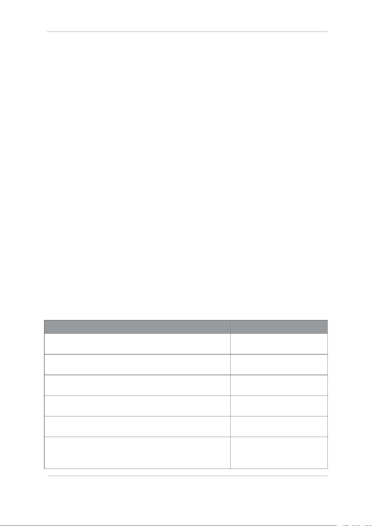
1.2 SOLO8 Software Defined Radio (Concealment)
1.2.1 Description
The SOLO8 Software Defined Radio is an ultra-miniature COFDM digital video transceiver from Domo
Tactical Communications (DTC), designed specifically for Point of View (PoV), body worn and concealment
applications. Dependent on the applications loaded, the platform can operate as a Transmitter, Receiver,
Dual Encoder, Standard IP Mesh and MIMO IP Mesh. Further information on software capability can found in
the SDRAPP datasheets.
The SOLO8 SDR Concealment is an ultra-miniature package ideal for integration into the smallest
concealment solutions.
The UHF version is larger than the standard SOL8SDR-C due to the lower frequency of operation (320470MHz). Please see the SOL8SDR UHF Operation Guidelines publication for important application notes.
One/two 2W PAs or a 2x1W PA can be connected via D1806 for extended range.
1.2.2 Features
Dual high profile HD H.264 independent video encoders
2x100mW COFDM transceivers for use as COFDM Transmitter, Receiver or IP Mesh
ISM band telemetry transceiver for control, PTZ and low power standby
Dual SD/HD-SDI video inputs for recording, transmission and analysis
Microphone inputs and headphone output for recording, transmission or talkback
Growing USB support for peripherals such as 3G/4G/Wi-Fi dongles
Ethernet, RS232 and RS485 connectivity, and 128GB built in storage
Compact packaging with ultra-miniature connectors
Page 8
SOL8SDR Hardware Guide
Commercial in Confidence
Revision 8.0
The information contained in this document is the property of Domo Tactical Communications (DTC) Ltd.
Any copying or reproduction in any form whatsoever is prohibited without the written permission of DTC.
© 2016 Copyright Domo Tactical Communications (DTC) Limited. All rights reserved.
Page 1-2
Very low power consumption: typically 7.5W
Exceptionally small size: 50mm x 50mm x 18mm (24mm UHF)
Weighs only 70-82g
1.2.3 Basic Specifications
Dimensions (mm)
50 (L) x 50 (W) x 18 (D)
Weight
80g
Operating Temperature
-20°C to +60°C with additional cooling
Power Consumption
Typically 7.5W (SD), 8.5W (HD), 9.5W (Dual)
DC Input
8 to 18VDC reverse polarity protected
DC Output
1A pass through switchable
1.3 SOLO8 Software Defined Radio (Robust)
1.3.1 Description
The SOLO8 Software Defined Radio is an ultra-miniature COFDM digital video transceiver from Domo
Tactical Communications (DTC), designed specifically for Point of View (PoV), body worn and concealment
applications. Dependent on the applications loaded the platform can operate as a Transmitter, Receiver,
Dual Encoder, Standard IP Mesh and MIMO IP Mesh. Further information on software capability can found in
the SDRAPP datasheets.
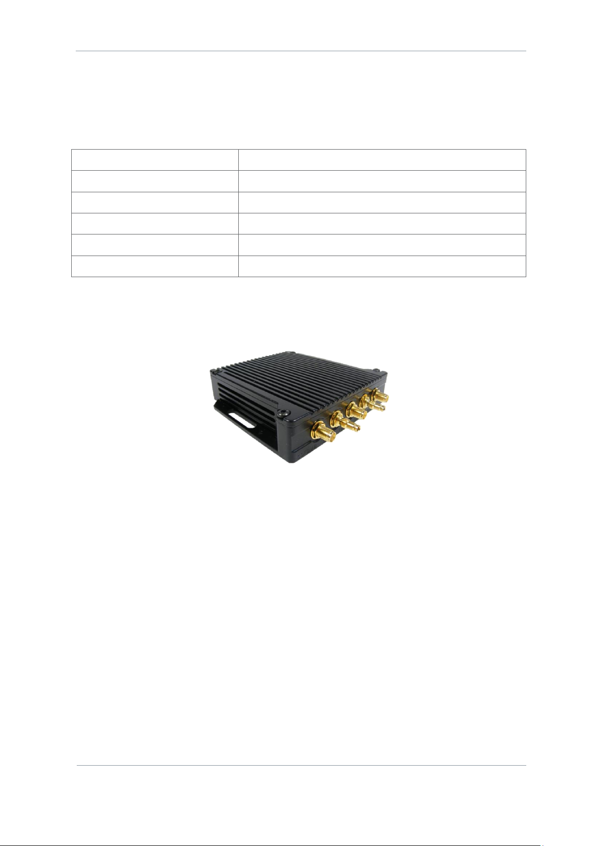
SOLO8 SDR Robust provides a passively cooled IP66 rated enclosure ideal for outdoor, or body worn
applications.
The UHF version is larger than the standard SOL8SDR-R due to the lower frequency of operation (320470MHz). Please see the SOL8SDR UHF Operation Guidelines publication for important application notes.
1.3.2 Features
Dual high profile HD H.264 independent video encoders
2x100mW COFDM transceivers for use as COFDM Transmitter, Receiver or IP Mesh
ISM band telemetry transceiver for control, PTZ and low power standby
Dual SD/HD-SDI video inputs for recording, transmission and analysis
Microphone inputs and headphone output for recording, transmission or talkback
Growing USB support for peripherals such as 3G/4G/Wi-Fi dongles
Page 9
SOL8SDR Hardware Guide
Commercial in Confidence
Revision 8.0
The information contained in this document is the property of Domo Tactical Communications (DTC) Ltd.
Any copying or reproduction in any form whatsoever is prohibited without the written permission of DTC.
© 2016 Copyright Domo Tactical Communications (DTC) Limited. All rights reserved.
Page 1-3
Ethernet, RS232 and RS485 connectivity, and 128GB built in storage
Robust packaging with IP66 rated connectors
Very low power consumption: typically 7.5W
Exceptionally small size: 130mm x 100mm x 25mm (30.5mm
UHF)
Weighs only 314-372g
1.3.3 Basic Specifications
Dimensions (mm)
130 (L) x 100 (W) x 25 (D)
Weight
314g
Operating Temperature
-20°C to +60°C
Power Consumption
Typically 7.5W (SD), 8.5W (HD), 9.5W (Dual)
DC Input
8 to 18VDC reverse polarity protected
DC Output
1A pass through switchable
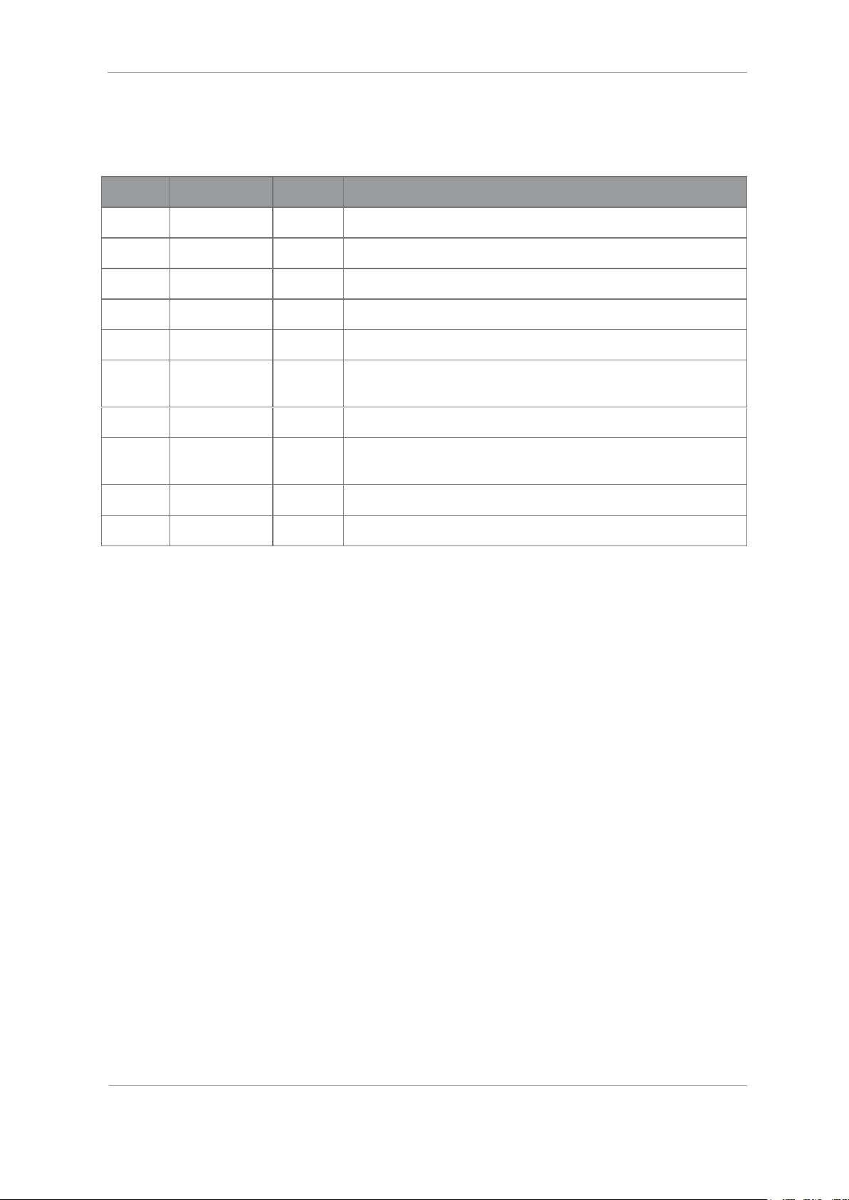
1.4 SOLO8 Software Defined Radio (Plain)
1.4.1 Description
The SOLO8 Software Defined Radio is an ultra-miniature COFDM digital video transceiver from Domo
Tactical Communications (DTC), designed specifically for Point of View (PoV), body worn and concealment
applications. Dependent on the applications loaded the platform can operate as a Transmitter, Receiver,
Dual Encoder, Standard IP Mesh and MIMO IP Mesh. Further information on software capability can found in
the SDRAPP datasheets.
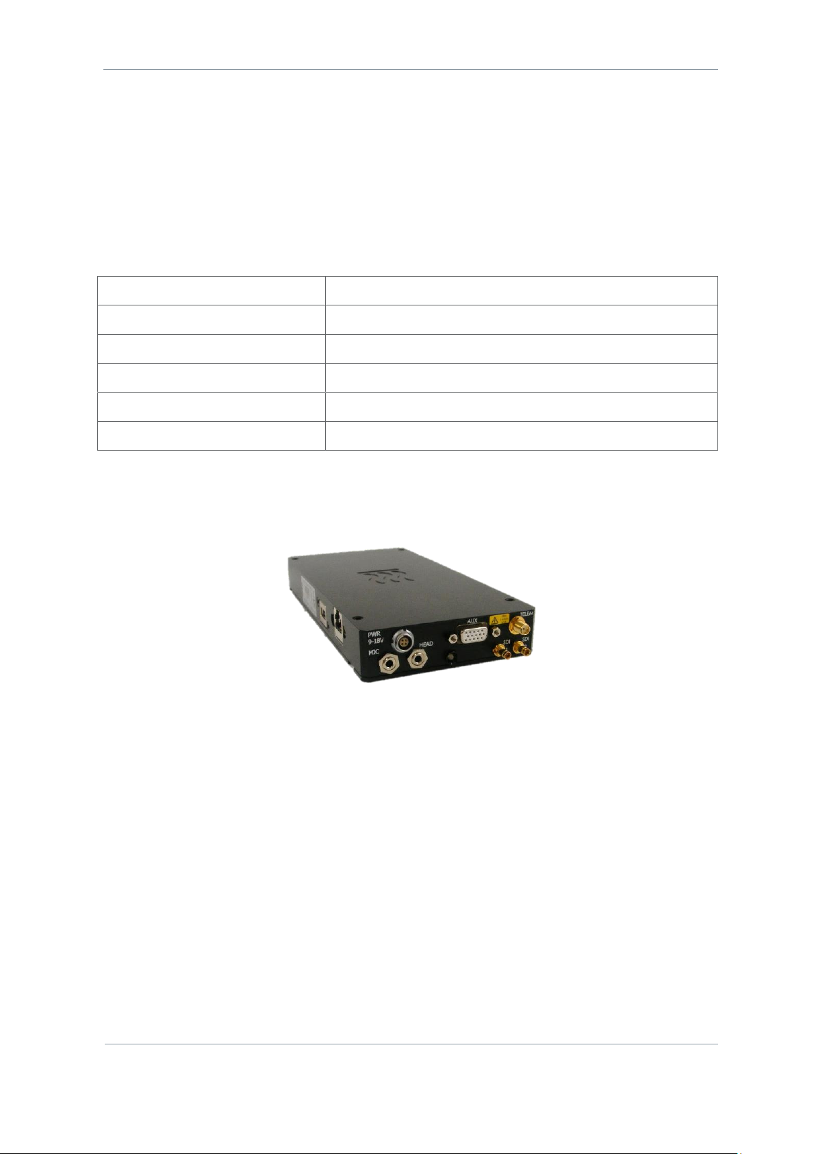
SOLO8 SDR Plain provides a compact higher power solution (2x2W) for increased range and enhanced
connectivity with native RJ45 and USB as standard.
1.4.2 Features
Dual high profile HD H.264 independent video encoders
2x2W COFDM transceivers for use as COFDM Transmitter, Receiver or IP Mesh
ISM band telemetry transceiver for control, PTZ and low power standby
Dual SD/HD-SDI video inputs for recording, transmission and analysis
Microphone inputs and headphone output for recording, transmission or talkback
Page 10
SOL8SDR Hardware Guide
Commercial in Confidence
Revision 8.0
The information contained in this document is the property of Domo Tactical Communications (DTC) Ltd.
Any copying or reproduction in any form whatsoever is prohibited without the written permission of DTC.
© 2016 Copyright Domo Tactical Communications (DTC) Limited. All rights reserved.
Page 1-4
Growing USB support for peripherals such as 3G/4G/Wi-Fi dongles
Ethernet, RS232 and RS485 connectivity and 128GB built in storage
Higher power packaging without the need for breakout cables
Very low power consumption: typically 12.5W
Exceptionally small size: 200mm x 100mm x 27mm
Weighs only 950g
1.4.3 Basic Specifications
Dimensions (mm)
235mm (L) x 100mm (W) x 26mm (H).
Weight
950g
Operating Temperature
-10°C to +50°C.
Power Consumption
Typically 12.5W (SD), 13.5W (HD), 14.5W (Dual).
DC Input
8 to 18VDC reverse polarity protected.
DC Output
1A pass through switchable. 5V regulated output limited to 1A (switchable)
1.5 Approval Notices
1.5.1 EMC/Safety and Radio Approvals
The equipment has been designed to meet and has been tested against harmonized EMC and safety
standards.
1.5.2 CE Marking
The CE mark is affixed to all DTC products, the CE Declaration of Conformity as well as the technical file is
available on request.
1.6 FCC EMC Compliance
1.6.1 Statement
Where SOL8SDR-C and SOL8SDR-P devices carry an FCC compliance identifier on the label (see section
2.7.2), the following statement applies:
This device complies with part 15 of the FCC Rules. Operation is subject to the condition that this
device does not cause harmful interference.
The use of frequencies not listed in the grant filing are prohibited.
Changes or modifications not expressly approved by Domo Tactical Communications (DTC) could void
the user’s authority to operate the equipment.
1.6.2 Test Criteria
The products which conform to the statement above were tested in 16-QAM and BPSK modulation schemes
and are authorised for use in these modes only.
Please refer to SOL8SDR Transmitter Software User Guide and SOL8SDR Mesh Software User Guide for
configuration control.
Page 11
SOL8SDR Hardware Guide
Commercial in Confidence
Revision 8.0
The information contained in this document is the property of Domo Tactical Communications (DTC) Ltd.
Any copying or reproduction in any form whatsoever is prohibited without the written permission of DTC.
© 2016 Copyright Domo Tactical Communications (DTC) Limited. All rights reserved.
Page 2-5
2. Product Package
2.1 Overview
Carefully open the packaging and remove the device and all other items. Verify that all the components
have been included in the package as shown in the packing list. Inspect the unit for shipping damage.
Note: If you do not have all the parts or you are not happy with the condition of your delivered product,
please call DTC and we will get this solved for you. See section 6.2.
Retain the packing list and all the packing materials for storage.
The codes in the packing list mean:
CA – cable assembly
SA – sub assembly
AP – assembly part
The part numbers are useful for identification and if you need to order a new part.
2.2 SOL8SDR-C Parts List
These items will be in the package.
Item
Notes
SOL8SDR-C
SOLO8 Software Defined Radio, Concealment (OEM)
CA2856
Ethernet JST cable
CA3043
JST-banana plug power cable
D1804
Gecko breakout PCB (for pinout see section 3.6)
D918
Ethernet Magnetics PCB
SA3774
SOL8SDR-C USB stick containing:
Device Controller, Node Finder, Video Download Tool, SDR USB driver, SOL8SDR
Hardware Guide, Software User Guides, Quick Start Guide and SOL8SDR-C
Integration Documentation
2.3 SOL8SDR-R Part List
These items will be in the package.
Item
Notes
SOL8SDR-R
SOLO8 Software Defined Radio, Robust
AP007377
USB A to micro USB B cable
CA0002
12V DC power cable 3m
CA2396 x 2
DIN 1.0/2.3 to BNC female cable
CA2519
Fischer power cable 3m
Page 12
SOL8SDR Hardware Guide
Commercial in Confidence
Revision 8.0
The information contained in this document is the property of Domo Tactical Communications (DTC) Ltd.
Any copying or reproduction in any form whatsoever is prohibited without the written permission of DTC.
© 2016 Copyright Domo Tactical Communications (DTC) Limited. All rights reserved.
Page 2-6
Item
Notes
CA2521
Fischer Ethernet breakout cable
CA2522
Fischer USB breakout cable
CA3123
Fischer audio MIC/HEAD cable
SA3741
SOL8SDR-R USB stick containing:
Device Controller, Node Finder, Video Download Tool, SDR USB driver, SOL8SDR
Hardware Guide, Software User Guides and Quick Start Guide
2.4 SOL8SDR2X2W-P Parts List
These items will be in the package.
Item
Notes
SOL8SDR2x2W-P
SOLO8 Software Defined Radio, Plain
CA0002
12VDC power cable 3m
CA2396 x 2
BNC to DIN 1.0/2.3 RG179 cable
CA3172
12V power block
SA4233
SOL8SDR-P USB stick containing:
Device Controller, Node Finder, Video Download Tool, SDR USB driver, SOL8SDR
Hardware Guide, Software User Guides and Quick Start Guide
Page 13
SOL8SDR Hardware Guide
Commercial in Confidence
Revision 8.0
The information contained in this document is the property of Domo Tactical Communications (DTC) Ltd.
Any copying or reproduction in any form whatsoever is prohibited without the written permission of DTC.
© 2016 Copyright Domo Tactical Communications (DTC) Limited. All rights reserved.
Page 2-7
2.5 Accessory Options
If you have purchased these items, they will also be in the package.
Note: If you have ordered the AMP2W or AMP2x1W, they will need to be calibrated with SOL8SDR-C using the
process detailed in SOL8SDR-C OEM Integration Document. A D1806 is an essential accessory.
Part Number
Equipment Title
SOL8SDR-CK
SOL8SDR Concealment Kit, including CAMuPHDK (HD-SDI pin-hole camera
and 3 lenses), microphone, ANT, battery, heatsink, Pelicase. Excludes
SOL8SDR-C.
SOL8SDR-RSK
SOL8SDR Robust Surveillance Kit, including CAMuPHDK (HD-SDI pin-hole
camera and 3 lenses), microphone, ANT, battery, heatsink, Pelicase.
Excludes SOL8SDR-R.
SOL8SDR-C-HSK
Passive heatsink assembly for SOL8SDR-C
SOL8SDR2x2W-P-HSK
Passive heatsink accessory for SOL8SDR2X2W-P only
SOL8KF-043
Three button key fob (433.05-434.79MHz)
SOL8KF-091
Three button key fob (902-928MHz)
SOL8SDI
HDMI/Composite to SDI converter
CAMuPHDK
Pin-hole HD camera kit
CA2830
DIN 1.0/2.3 to MMCX cable for CAMuPHDK
SOL8TELTRX
SOLO8 Telemetry Transmitter/Receiver
AMP2W-xxxxxx-B-OEM
2W PA OEM assembly with bypass, xxxxxx denotes frequency band
(SOL8SDR-C only)
AMP2x1W-xxxxxx-B-OEM
Dual 1W OEM AMP with bypass, xxxxxx denotes frequency band (SOL8SDRC only)
D1806
Gecko active breakout PCB required for PA accessories (SOL8SDR-C only)
SOL8SDR-C-CAKIT-A/B/C
Cable accessory kits A, B and C for SOL8SDR-C. Refer to CAKIT guide.
CA2520
AV/PTZ/data breakout cable (SOL8SDR-R only)
CA3164
Fischer DC/USB/RS485 Wire Breakout (SOL8SDR-R only)
CA3238
GlobalSat BU-353-S4 GPS with UltiMate (SOL8SDR-R only)
AP009131
GlobalSat BU-353-S4 GPS with Type-A USB
2.6 Variants
This part number will identify the product; it is also on the label.
2.6.1 SOL8SDR-C
Part Number
Description
SOL8SDR-C-039091
Software Defined Radio, Concealment, 320-470MHz, 902-928MHz Tel
Page 14
SOL8SDR Hardware Guide
Commercial in Confidence
Revision 8.0
The information contained in this document is the property of Domo Tactical Communications (DTC) Ltd.
Any copying or reproduction in any form whatsoever is prohibited without the written permission of DTC.
© 2016 Copyright Domo Tactical Communications (DTC) Limited. All rights reserved.
Page 2-8
Part Number
Description
SOL8SDR-C-132043
Software Defined Radio, Concealment, 1.14-1.50GHz, 433.05-434.79MHz Tel
SOL8SDR-C-201043
Software Defined Radio, Concealment, 1.67-2.35GHz, 433.05-434.79MHz Tel
SOL8SDR-C-201091
Software Defined Radio, Concealment, 1.67-2.35GHz, 902-928MHz Tel
SOL8SDR-C-234043
Software Defined Radio, Concealment, 1.98-2.7GHz, 433.05-434.79MHz Tel
SOL8SDR-C-234091
Software Defined Radio, Concealment, 1.98-2.7GHz, 902-928MHz Tel
SOL8SDR-C-470043
Software Defined Radio, Concealment, 4.40-5.00GHz, 433.05-434.79MHz Tel
SOL8SDR-C-470091
Software Defined Radio, Concealment, 4.40-5.00GHz, 902-928MHz Tel
SOL8SDR-C-575091
Software Defined Radio, Concealment, 5.50-6.00GHz, 902-928MHz Tel
2.6.2 SOL8SDR-R
Part Number
Description
SOL8SDR-R-039091
Software Defined Radio, Robust, 320-470MHz, 902-928MHz Tel
SOL8SDR-R-132043
Software Defined Radio, Robust, 1.14-1.50GHz, 433.05-434.79MHz Tel
SOL8SDR-R-201043
Software Defined Radio, Robust, 1.67-2.35GHz, 433.05-434.79MHz Tel
SOL8SDR-R-201091
Software Defined Radio, Robust, 1.67-2.35GHz, 902-928MHz Tel
SOL8SDR-R-234043
Software Defined Radio, Robust, 1.98-2.7GHz, 433.05-434.79MHz Tel
SOL8SDR-R-234091
Software Defined Radio, Robust, 1.98-2.7GHz, 902-928MHz Tel
SOL8SDR-R-470043
Software Defined Radio, Robust, 4.40-5.00GHz, 433.05-434.79MHz Tel
SOL8SDR-R-470091
Software Defined Radio, Robust, 4.40-5.00GHz, 902-928MHz Tel
SOL8SDR-R-575091
Software Defined Radio, Robust, 5.50-6.00GHz, 902-928MHz Tel
2.6.3 SOL8SDR2x2W-P
Part Number
Description
SOL8SDR2x2W-P-132043
Software Defined Radio, Plain, 2x2W, 1.14-1.50GHz, 433.05-434.79MHz Tel
SOL8SDR2x2W-P-201043
Software Defined Radio, Plain, 2x2W, 1.67-2.35GHz, 433.05-434.79MHz Tel
SOL8SDR2x2W-P-201091
Software Defined Radio, Plain, 2x2W, 1.67-2.35GHz, 902-928MHz Tel
SOL8SDR2x2W-P-234043
Software Defined Radio, Plain, 2x2W, 1.98-2.70GHz, 433.05-434.79MHz Tel
SOL8SDR2x2W-P-234091
Software Defined Radio, Plain, 2x2W, 1.98-2.70GHz, 902-928MHz Tel
SOL8SDR2x2W-P -470091
Software Defined Radio, Plain, 2x2W, 4.40-5.00GHz, 902-928MHz Tel
Page 15
SOL8SDR Hardware Guide
Commercial in Confidence
Revision 8.0
The information contained in this document is the property of Domo Tactical Communications (DTC) Ltd.
Any copying or reproduction in any form whatsoever is prohibited without the written permission of DTC.
© 2016 Copyright Domo Tactical Communications (DTC) Limited. All rights reserved.
Page 2-9
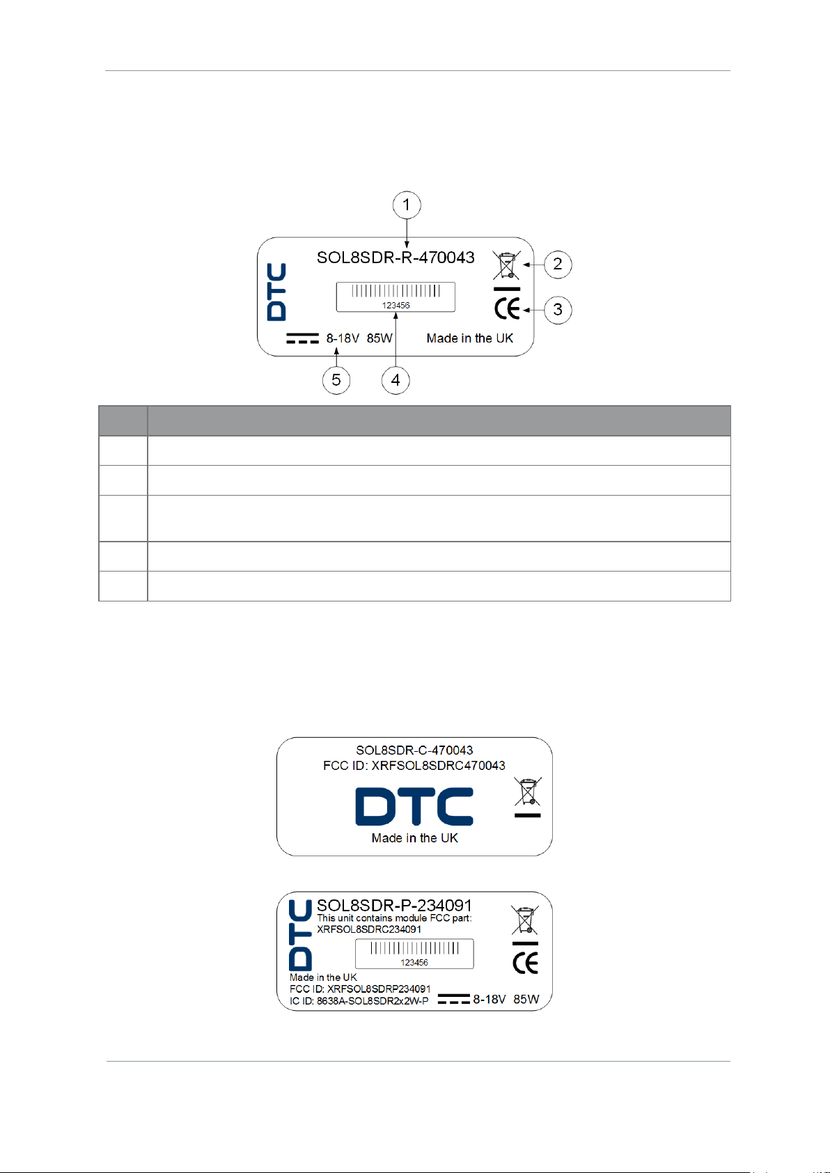
2.7 Labelling
2.7.1 Generic
All SOL8SDRs will be identified by generic label information.
No
Item
1
Part number – this is the variant explained above.
2
This symbol indicates that the unit should be disposed of in accordance with the WEEE Directive.
3
The CE mark certifies that a product has met EU consumer safety, health and environmental
requirements.
4
A barcoded, six-digit serial number. This may be required during a support call.
5
Power requirements.
2.7.2 SOL8SDR FCC Labelling
An FCC ID is a unique identifier assigned to a device registered with the United States Federal
Communications Commission, see section 1.6.
Where SOL8SDR is certified, the FCC identifier will be indicated on the label.
SOL8SDR-C FCC Label
SOL8SDR-P FCC Label
Page 16
SOL8SDR Hardware Guide
Commercial in Confidence
Revision 8.0
The information contained in this document is the property of Domo Tactical Communications (DTC) Ltd.
Any copying or reproduction in any form whatsoever is prohibited without the written permission of DTC.
© 2016 Copyright Domo Tactical Communications (DTC) Limited. All rights reserved.
Page 2-10
2.8 Licensing Options
Some product functions are enabled by licenses.
SDR applications are used in combination with SOL8SDR products to add functionality. Combinations of
SDRAPP licenses may need to be purchased to meet the requirements.
2.8.1 SDRAPP-ENC
If the SOL8SDR is to be used as a Video Encoder, choose from the SDRAPP-ENC licenses.
Part Number
SDRAPP-ENC
Silver
Streaming and Recording
Gold
Silver plus MPEG-4 H.264 (SD)
Platinum
Gold plus MPEG-4 H.264 (HD)
2.8.2 SDRAPP-TX
If the SOL8SDR is to be used as a COFDM Transmitter, choose from the SDRAPP-TX licenses.
Part Number
SDRAPP-TX
Silver
DVB-T Modulation, Ultra Mobile Video Link (UMVL) and Telemetry.
Gold
Silver plus 1.25MHz and 2.5MHz Narrowband Modulation.
Platinum
Gold plus 625MHz Narrowband Modulation.
2.8.3 SDRAPP-RX
If the SOL8SDR is to be used as a Receiver, choose from the SDRAPP-RX licenses.
Part Number
SDRAPP-TX
Silver
DVB-T Modulation and Telemetry.
Gold
Silver plus 1.25MHz and 2.5MHz Narrowband Modulation.
Platinum
Gold plus 625MHz Narrowband Modulation.
2.8.4 SDRAPP-MESH
If the SOL8SDR is to be used as a Mesh IP Radio, the SDRAPP-MESH license will need to be applied.
Part Number
SDRAPP-MESH
Silver
Standard Mesh, MIMO Mesh and DES Mesh Encryption.
2.8.5 SDRAPP-IAS
If the SOL8SDR Mesh is to use the Interference Avoidance Scheme, the SDRAPP-IAS license will need to be
applied.
Part Number
SDRAPP-MESH
Silver
Interference Avoidance Scheme.
Page 17

SOL8SDR Hardware Guide
Commercial in Confidence
Revision 8.0
The information contained in this document is the property of Domo Tactical Communications (DTC) Ltd.
Any copying or reproduction in any form whatsoever is prohibited without the written permission of DTC.
© 2016 Copyright Domo Tactical Communications (DTC) Limited. All rights reserved.
Page 2-11
2.8.6 Encryption
Encryption licenses are used for secure communications.
Part Number
SDRAPP-TX
AES128TX
AES 128-Bit Encryption License
AES256TX
AES 256-Bit Encryption License
Page 18
SOL8SDR Hardware Guide
Commercial in Confidence
Revision 8.0
The information contained in this document is the property of Domo Tactical Communications (DTC) Ltd.
Any copying or reproduction in any form whatsoever is prohibited without the written permission of DTC.
© 2016 Copyright Domo Tactical Communications (DTC) Limited. All rights reserved.
Page 3-12
3. Connections, Controls and Indicators
3.1 Introduction
This chapter will help you identify all the connections and interfaces to help you install and control your
SOL8SDR device.
Each SOL8SDR has front and rear panels which contain all the interfaces for the unit. The SOL8SDR2X2W-P
also has a left panel with some connections.
3.2 Antenna Polarization
3.2.1 COFDM Transmitter/Receiver
COFDM links are very robust and are tolerant to changes in antenna location, but, it is important to try and
keep the antennas in the same plane if possible.
The antennas used with the COFDM links are usually linearly polarized.
3.2.2 MIMO Mesh
MIMO Mesh antennas are ideally polarised orthogonally, at right angles to each other.
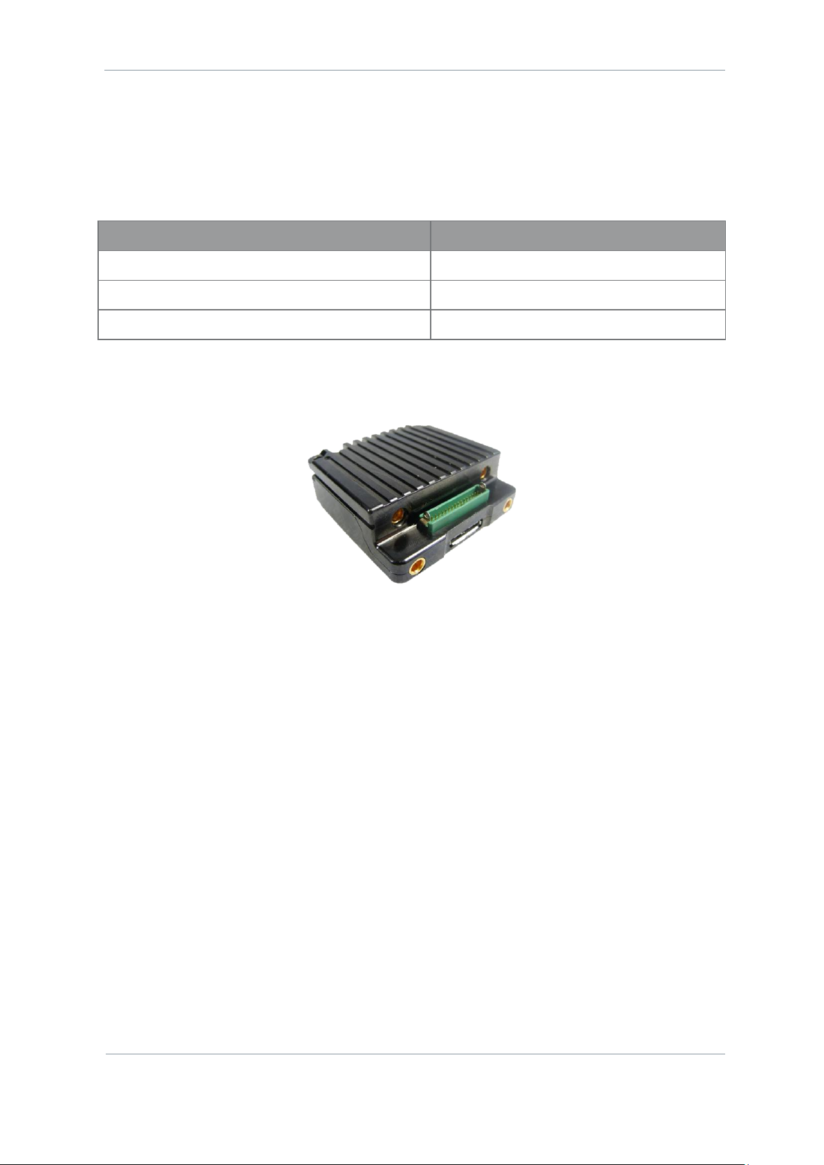
3.3 SOL8SDR Concealment
CAUTION: The SOL8SDR-C product is an OEM module which will need careful consideration for heatsinking
or fan cooling as part of the installation. Please read SOL8SDR-C OEM Integration Document available on
DTC’s WatchDox facility.
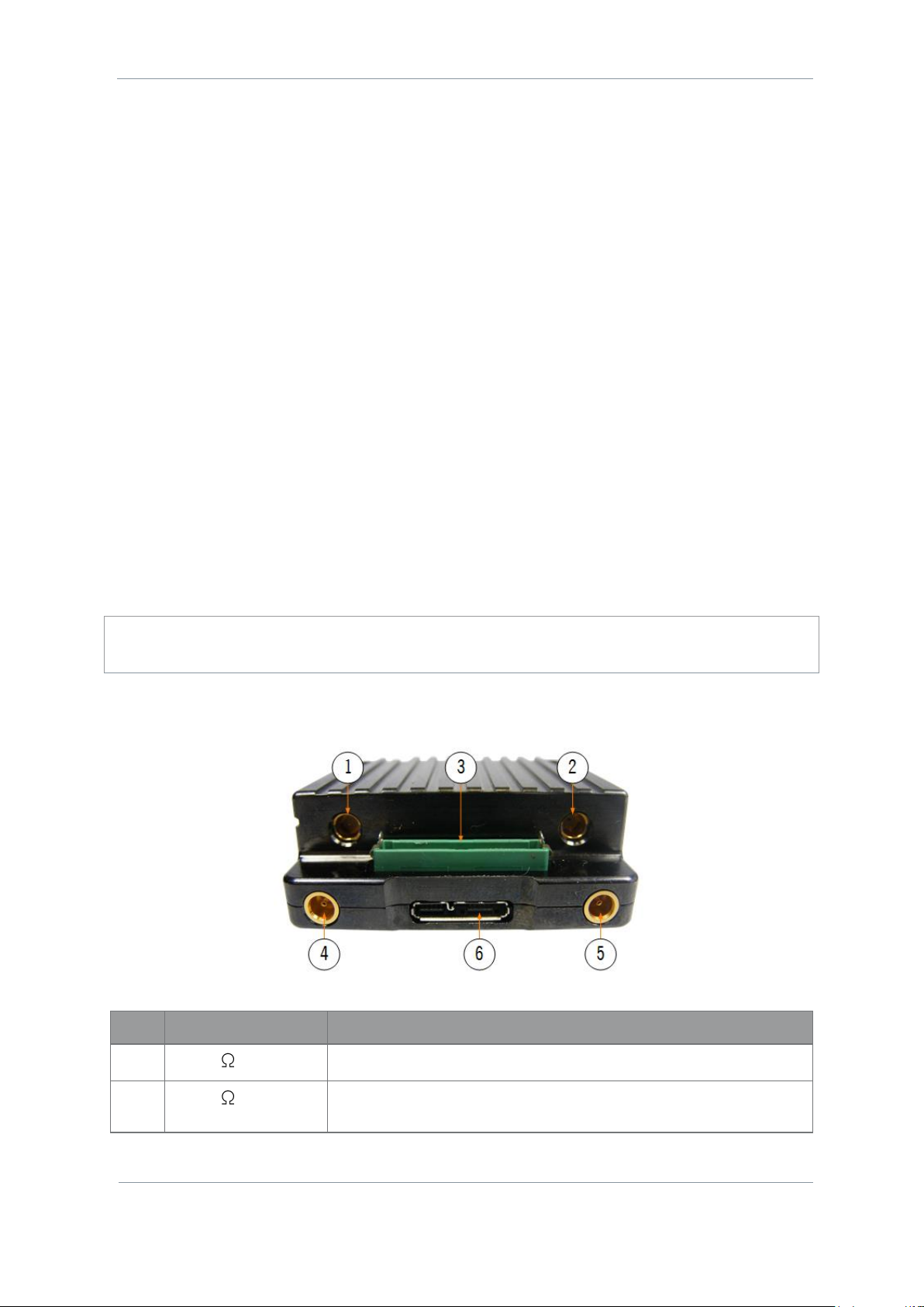
3.3.1 Front Panel
No
Item
Purpose
1
SMP 50 jack (pin)
RF-A COFDM antenna connects here.
2
SMP 50 jack (pin)
RF-B COFDM antenna connects here. This is the default transmit
output.
Page 19

SOL8SDR Hardware Guide
Commercial in Confidence
Revision 8.0
The information contained in this document is the property of Domo Tactical Communications (DTC) Ltd.
Any copying or reproduction in any form whatsoever is prohibited without the written permission of DTC.
© 2016 Copyright Domo Tactical Communications (DTC) Limited. All rights reserved.
Page 3-13
No
Item
Purpose
3
Harwin Gecko 34-way
header
This header accepts D1804 Gecko breakout PCB supplied with the unit
which breaks out to:
Power in, power out, Ethernet, PTZ control, RS232 debug, PA control,
headphone out, and left and right microphone inputs.
For pinout of the Gecko breakout PCB see section 3.6.
Note: If you have a power amplifier, you will need the D1806 PCB. For
integration, read the SOL8SDR-C OEM Integration Document.
4
MCX jack (socket)
SDI-1 video connects here.
5
MCX jack (socket)
SDI-2 video connects here.
6
USB 3.0 Micro-B jack
Use DTC cable AP007377 to connect to your PC.
A USB to serial adaptor can be used for serial data transfer.
If you want to attach USB peripheral devices, you will need a suitable
micro B to type A female adaptor.
3.3.2 Rear Panel
No
Item
Purpose
1
Threaded mounting
British Standard Whitworth (BSW) 1/4” x 20 for mounting.
2
SMP 50 jack (pin)
Telemetry antenna connects here.
Page 20

SOL8SDR Hardware Guide
Commercial in Confidence
Revision 8.0
The information contained in this document is the property of Domo Tactical Communications (DTC) Ltd.
Any copying or reproduction in any form whatsoever is prohibited without the written permission of DTC.
© 2016 Copyright Domo Tactical Communications (DTC) Limited. All rights reserved.
Page 3-14
3.4 SOL8SDR Robust
3.4.1 Front Panel
No
Item
Purpose
1
SMA 50 jack (socket)
COFDM B antenna connects here. This is the default transmit
output.
2
SMA 50 jack (socket)
COFDM A antenna connects here.
3
SMA 50 jack (socket)
Telemetry antenna connects here.
4
DIN 1.0/2.3 jack (socket)
SDI-1 video connects here.
Note: SOL8SDI option will allow for a Composite or HDMI video
connection.
5
DIN 1.0/2.3 jack (socket)
SDI-2 video connects here.
Note: SOL8SDI option will allow for a Composite or HDMI video
connection.
3.4.2 Rear Panel
Note: For pinout of the four Fischer connectors, USB/485, ETH, Aud/232 and PWR, refer to section 3.7.
No
Item
Purpose
1
Fischer Ultimate 5-way jack
(pins) marked PWR
CA2519 (replaced by CA3173) connects here to provide 12V
Power In.
Page 21

SOL8SDR Hardware Guide
Commercial in Confidence
Revision 8.0
The information contained in this document is the property of Domo Tactical Communications (DTC) Ltd.
Any copying or reproduction in any form whatsoever is prohibited without the written permission of DTC.
© 2016 Copyright Domo Tactical Communications (DTC) Limited. All rights reserved.
Page 3-15
No
Item
Purpose
2
Fischer Ultimate10-way jack
(sockets) marked Aud/232
CA3123 connects here to provide Mesh audio talkback.
CA2520 (option) connects here to provide analogue audio in
left/right and RS232.
3
Fischer Ultimate10-way jack
(sockets) marked ETH
CA2521 connects here to provide Ethernet connectivity to a
laptop or network.
4
Fischer Ultimate10-way jack
(sockets) marked USB/485
CA2522 connects here to provide USB connectivity.
Use with supplied cable AP007377 to connect to a PC.
A USB to serial adaptor can be used for serial data transfer.
If you want to attach USB peripheral devices, you will need a
suitable micro B to type A female adaptor.
3.5 SOL8SDR Plain
3.5.1 Front Panel
No
Item
Purpose
1
Lemo 4-way jack
(sockets)
CA0002 or CA0023 can be inserted here to provide power.
2
3.5mm jack (socket)
Microphone audio signals can be connected here.
3
3.5mm jack (socket)
Headphone audio signals can be connected here.
4
Status LED
Power/RF status.
Red = power on/RF off
Green = power on/RF on in transmitter mode or when a successful
Mesh link has been established in Mesh mode.
5
High density D-type 15way connector (sockets)
Auxiliary port. For pinout see section 3.8.
6
DIN 1.0/2.3 jack (socket)
SDI1 video input connects here.
Note: SOL8SDI option will allow for a Composite or HDMI video
connection.
Page 22

SOL8SDR Hardware Guide
Commercial in Confidence
Revision 8.0
The information contained in this document is the property of Domo Tactical Communications (DTC) Ltd.
Any copying or reproduction in any form whatsoever is prohibited without the written permission of DTC.
© 2016 Copyright Domo Tactical Communications (DTC) Limited. All rights reserved.
Page 3-16
No
Item
Purpose
7
DIN 1.0/2.3 jack (socket)
SDI2 video input connects here.
Note: SOL8SDI option will allow for a Composite or HDMI video
connection.
8
SMA 50 jack (socket)
The telemetry antenna connects here.
3.5.2 Rear Panel
No
Item
Purpose
1
SMA 50 jack (socket)
COFDM B antenna. This is the default transmit output.
2
SMA 50 jack (socket)
COFDM A antenna.
3.5.3 The Left Panel
No
Item
Purpose
1
USB 2.0 4-way type A jack
Provides USB connectivity for host or peripheral devices.
A USB to serial adaptor can be used for serial data transfer.
2
Magjack RJ45 8-way jack
Provides Ethernet connectivity.
Page 23

SOL8SDR Hardware Guide
Commercial in Confidence
Revision 8.0
The information contained in this document is the property of Domo Tactical Communications (DTC) Ltd.
Any copying or reproduction in any form whatsoever is prohibited without the written permission of DTC.
© 2016 Copyright Domo Tactical Communications (DTC) Limited. All rights reserved.
Page 3-17
3.5.4 Top Panel
On the SOL8SDR2X2W-P top panel there is a thermal path indicator. This indicator is to alert the customer
to use this panel to provide the most effective heatsink path.
For assembly of the optional heatsink accessory see section 5.2.
3.6 SOL8SDR-C (D1804) Pinouts
3.6.1 D1804 PCB Assembly
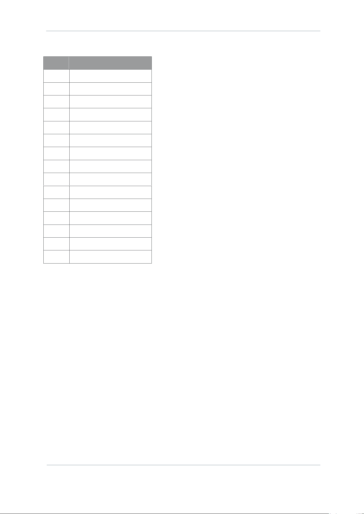
3.6.2 J1
Pin
Function
Pin
Function
1
GPIO0
2
GPIO1
3
VIN 4 0V
5
12V SW OUT
6
0V
7
Ethernet MDIP0
8
Ethernet MDIP2
9
Ethernet MDIN0
10
Ethernet MDIN2
11
Ethernet MDIP1
12
Ethernet MDIP3
13
Ethernet MDIN1
14
Ethernet MDIN3
15
0V
16
0V
17
RS232 TX
18
RS232 RX
19
RS485 TX+
20
RS485 RX+
21
RS485 TX-
22
RS485 RX-
23
GPIO2
24
GPIO3
25
PA TDD
26
0V
Page 24

SOL8SDR Hardware Guide
Commercial in Confidence
Revision 8.0
The information contained in this document is the property of Domo Tactical Communications (DTC) Ltd.
Any copying or reproduction in any form whatsoever is prohibited without the written permission of DTC.
© 2016 Copyright Domo Tactical Communications (DTC) Limited. All rights reserved.
Page 3-18
Pin
Function
Pin
Function
27
Headphone GND
28
Headphone Right
29
Microphone 10V
30
Microphone 10V
31
Microphone GND
32
Microphone GND
33
Microphone Left
34
Microphone Right
3.6.3 J2 (PWR)
Pin
Function
1
VIN
2
VIN
3
0V 4 0V 5 PA TDD
6
0V
3.6.4 J3 (RS232)
Pin
Function
1
RS232 TX
2
RS232 RX
3
OV
4
12V SW OUT
3.6.5 J4 (ETHERNET)
Pin
Function
1
Ethernet MDIP0
2
Ethernet MDIN0
3
Ethernet MDIP1
4
Ethernet MDIN1
5
Ethernet MDIP2
6
Ethernet MDIN2
7
Ethernet MDIP3
8
Ethernet MDIN3
9
0V
10
N/C
Page 25

SOL8SDR Hardware Guide
Commercial in Confidence
Revision 8.0
The information contained in this document is the property of Domo Tactical Communications (DTC) Ltd.
Any copying or reproduction in any form whatsoever is prohibited without the written permission of DTC.
© 2016 Copyright Domo Tactical Communications (DTC) Limited. All rights reserved.
Page 3-19
3.6.6 J5 (AUDIO)
Pin
Function
1
Microphone 10V
2
Microphone Left
3
Microphone GND
4
Microphone 10V
5
Microphone Right
6
Microphone GND
7
Headphone GND
8
Headphone Right
3.6.7 J6 (RS485/GPIO)
Pin
Function
1
12V SW OUT
2
0V
3
RS485 RX+
4
RS485 RX-
5
RS485 TX+
6
RS485 TX-
7
GPIO0
8
GPIO1
9
0V
10
GPIO2
11
GPIO3
Page 26

SOL8SDR Hardware Guide
Commercial in Confidence
Revision 8.0
The information contained in this document is the property of Domo Tactical Communications (DTC) Ltd.
Any copying or reproduction in any form whatsoever is prohibited without the written permission of DTC.
© 2016 Copyright Domo Tactical Communications (DTC) Limited. All rights reserved.
Page 3-20
3.7 SOL8SDR-R Pinouts
3.7.1 PWR
Pin
Function
1
VBATT Input
2
VBATT Input
3
GND
4
GND
5
PA TDD
3.7.2 AUD/232
Pin
Function
1
VBATT Output
2
GND
3
Headphone Output
4
Headphone GND
5
RS232 TX
6
RS232 RX
7
Microphone 10V
8
Microphone Left
9
Microphone Right
10
Microphone GND
3.7.3 ETH
Pin
Function
1
VCC
2
GND
3
Ethernet MDIN3
4
Ethernet MDIP3
5
Ethernet MDIN2
6
Ethernet MDIP2
7
Ethernet MDIN1
8
Ethernet MDIP1
9
Ethernet MDIN0
Page 27

SOL8SDR Hardware Guide
Commercial in Confidence
Revision 8.0
The information contained in this document is the property of Domo Tactical Communications (DTC) Ltd.
Any copying or reproduction in any form whatsoever is prohibited without the written permission of DTC.
© 2016 Copyright Domo Tactical Communications (DTC) Limited. All rights reserved.
Page 3-21
Pin
Function
10
Ethernet MDIP0
3.7.4 USB/485
Pin
Function
1
GND
2
USB ID
3
USB DP
4
USB DM
5
USB VBUS
6
RS485 TX+
7
RS485 TX-
8
RS485 RX+
9
RS485 RX-
10
VBATT Output
3.8 SOL8SDR2X2W-P Pinouts
3.8.1 Audio Jack
HEAD
Pin
Function
Tip
Audio Out (mono)
Ring 1
Audio Out (mono)
Ring 2
Ground
Sleeve
Ground
MIC
Pin
Function
Tip
Audio In Left
Ring 1
Audio In Right
Ring 2
Ground
Sleeve
Ground
Page 28
SOL8SDR Hardware Guide
Commercial in Confidence
Revision 8.0
The information contained in this document is the property of Domo Tactical Communications (DTC) Ltd.
Any copying or reproduction in any form whatsoever is prohibited without the written permission of DTC.
© 2016 Copyright Domo Tactical Communications (DTC) Limited. All rights reserved.
Page 3-22
3.8.2 Auxiliary Port
Pin
Function
1
RS485 TX+
2
RS485 TX-
3
GND
4
RS485 RX+
5
RS485 RX-
6
12V OUT
7
5V
8
No Connect
9
GND
10
RS232 TX
11
RS232 RX
12
GND
13
No Connect
14
No Connect
15
GND
3.1 Supported USB Dongles
3.1.1 4G Dongle
4G dongles that are currently supported:
Huawei E3372s-153 (pid 157d)
Huawei E3372h-153 (pid 1f01)
Verizon MiFi USB620L 4G (USA)
3.1.2 Wi-Fi Dongle
Wi-Fi dongles that are currently supported:
TP-LINK AC1300
TP-LINK AC1200
Page 29

SOL8SDR Hardware Guide
Commercial in Confidence
Revision 8.0
The information contained in this document is the property of Domo Tactical Communications (DTC) Ltd.
Any copying or reproduction in any form whatsoever is prohibited without the written permission of DTC.
© 2016 Copyright Domo Tactical Communications (DTC) Limited. All rights reserved.
Page 3-23
3.2 SOL8SDI Option as a Video Source
Composite or HDMI video signals can also be used as a source for SOL8SDR by using a SOL8SDI option to
convert the signal source to SDI.
Note: SOL8SDI receives 5VDC power from the SOL8SDR. This is configurable from Domo Device Controller
Video Source selection.
No
Item
Function
1
SOL8DI
Primary unit.
2
DIN1.0/2.3 2-way jack (socket)
PAL or NTSC composite video input connects here.
3
Micro HDMI type-D socket
HDMI video input connects here.
4
HD-BNC 75R jack (socket)
SD-SDI or HD-SDI video output here.
5
CA2847 HD-BNC plug (pin)
Connect this to SOL8SDI SDI OUT connector.
6
CA2847 DIN 1.0/2.3 2-way plug (pin)
Connect this to SOL8SDR-R SDI input.
7
CA3044 HD-BNC plug (pin)
Connect this to SOL8SDI SDI OUT connector
8
CA3044 MCX 75R plug (pin)
Connect this to SOL8SDR-C SDI input.
Page 30

SOL8SDR Hardware Guide
Commercial in Confidence
Revision 8.0
The information contained in this document is the property of Domo Tactical Communications (DTC) Ltd.
Any copying or reproduction in any form whatsoever is prohibited without the written permission of DTC.
© 2016 Copyright Domo Tactical Communications (DTC) Limited. All rights reserved.
Page 4-24
4. Getting Started
4.1 Introduction
This chapter will help the user power up and communicate with their SOL8SDR product. It will explain
installation instructions for any relevant applications.
4.2 Initial Connections
Once you have unpacked your SOL8SDR, you will need to provide 12VDC power and connect to a PC or
Network using Ethernet for control.
There is no power switch on a SOL8SDR, as soon as the power supply is switched on, your device will boot
up.
4.3 Access the USB Stick
The USB support stick contents will provide you with all the user guides and applications needed to operate
a SOL8SDR.
Plug the USB stick into the USB port of your PC.
The USB stick device drivers will load the first time you plug it in to your PC. Wait for the drivers to load
successfully, you should see the progress in the bottom right of your PC screen.
Once they have loaded, a USB drive will have been created. Open Windows Explorer and you will be able
to view the USB stick contents.
4.4 Using Node Finder
Our devices are shipped to you with the IP DHCP setting enabled. This means that if your SOL8SDR is
connected to a network which is administered by a DHCP server, the IP address will be automatically
allocated to it.
Node Finder can be used to identify a device IP address, or disable DHCP if you are not connected through a
DHCP server or using a standalone PC or laptop.
If you are unsure about your server settings, check with your Network Administrator.
Note: If you are using a standalone PC or laptop, you will also need to set the IP address of the PC. Refer to
section 5.1 to find out how to do this.
If the DTC device is connected to a network which does not have a DHCP server, contact your Network
Administrator for an IP address you can use.
Page 31

SOL8SDR Hardware Guide
Commercial in Confidence
Revision 8.0
The information contained in this document is the property of Domo Tactical Communications (DTC) Ltd.
Any copying or reproduction in any form whatsoever is prohibited without the written permission of DTC.
© 2016 Copyright Domo Tactical Communications (DTC) Limited. All rights reserved.
Page 4-25
4.4.1 Install Node Finder on your PC
Double click the NodeFinder.exe file from the USB drive on your PC.
The Node Finder Setup window opens.
Browse to the location where you wish to install the software or leave the Destination Folder at default
(recommended).
Click the Install button.
On completion Close the installer. A Node Finder icon will appear on your desktop.
4.4.2 Establish IP Address using Node Finder
Double click the newly installed Node Finder icon from your PC desktop.
Establish the SOL8SDR IP address from Node Finder.
Note: If the device is not connected to a network with a DHCP server, the IP address may appear as 0.0.0.0.
Right click on the SOL8SDR to disable DHCP and set the IP address, if required.
Page 32

SOL8SDR Hardware Guide
Commercial in Confidence
Revision 8.0
The information contained in this document is the property of Domo Tactical Communications (DTC) Ltd.
Any copying or reproduction in any form whatsoever is prohibited without the written permission of DTC.
© 2016 Copyright Domo Tactical Communications (DTC) Limited. All rights reserved.
Page 4-26
4.5 Installing the Domo Device Controller
Note: Domo Device Controller will only connect to a device which is configured as a Transmitter. If
configured as a Receiver or Mesh, use the web browser.
4.5.1 Install the Domo Device Controller on your PC
Double-click the DomoDeviceController-Installer.exe on your USB stick.
The Domo Device Controller Setup window opens.
Browse to the location where you wish to install the software (or leave at default).
Click the Install button.
On successful completion, close the installer. A desktop icon will have been created.
Page 33

SOL8SDR Hardware Guide
Commercial in Confidence
Revision 8.0
The information contained in this document is the property of Domo Tactical Communications (DTC) Ltd.
Any copying or reproduction in any form whatsoever is prohibited without the written permission of DTC.
© 2016 Copyright Domo Tactical Communications (DTC) Limited. All rights reserved.
Page 4-27
4.6 Using a Web Browser Application
4.6.1 Connect Using a Web Browser Application
On your PC, open a web browser application.
In the Address Bar, enter the IP address of the SOL8SDR that was discovered using Node Finder.
The Windows Security dialog box opens.
Leave the Username blank and enter the Password as Eastwood (this is case sensitive).
Click OK.
Your SOL8SDR Control Page opens.
The actual appearance of the web browser will depend on the SDR application that is configured in the
Configuration>Global tab. This is an example of a SOL8SDR configured as a transmitter.
Page 34

SOL8SDR Hardware Guide
Commercial in Confidence
Revision 8.0
The information contained in this document is the property of Domo Tactical Communications (DTC) Ltd.
Any copying or reproduction in any form whatsoever is prohibited without the written permission of DTC.
© 2016 Copyright Domo Tactical Communications (DTC) Limited. All rights reserved.
Page 4-28
4.7 Configure the SOL8SDR Application
You may need to change the application if you have more than one SDRAPP license installed.
Open the web browser application and go to the Configuration>Global tab. Change the Application setting
to suit, there is a choice of SOL-TX, SOL-RX and MESH.
Note: If you only have the SDRAPP-ENC license, the SOL8SDR will need to be configured as a SOL-TX.
4.8 Passwords
The default password for the SOL8SDR is Eastwood with no username necessary. This username is
applicable for all user application logins, if necessary (i.e. Milestone, ONVIF etc.).
Some specific SOL8SDR applications may use alternative passwords.
Page 35

SOL8SDR Hardware Guide
Commercial in Confidence
Revision 8.0
The information contained in this document is the property of Domo Tactical Communications (DTC) Ltd.
Any copying or reproduction in any form whatsoever is prohibited without the written permission of DTC.
© 2016 Copyright Domo Tactical Communications (DTC) Limited. All rights reserved.
Page 4-29
4.9 Using Domo Device Controller via IP
4.9.1 Before you start
You will need:
A Personal Computer with the Domo Device Controller and Node Finder installed
Connect and apply power to the SOL8SDR
Connect the SOL8SDR to the PC or Network via Ethernet
Note: Ensure the SDR is configured as a Transmitter (this can be verified in the web browser). Device
controller will not work if SOL8SDR is configured as a Mesh or Receiver.)
4.9.2 Connect Using Domo Device Controller
On your desktop, double-click the Domo Device Controller icon.
The Domo Device Controller opens showing the Splash Screen.
Click the orange Connect button.
Page 36

SOL8SDR Hardware Guide
Commercial in Confidence
Revision 8.0
The information contained in this document is the property of Domo Tactical Communications (DTC) Ltd.
Any copying or reproduction in any form whatsoever is prohibited without the written permission of DTC.
© 2016 Copyright Domo Tactical Communications (DTC) Limited. All rights reserved.
Page 4-30
The Device Connection window opens.
Select TCP Socket from the drop-down list.
Type the IP address of the SOLO8 or click the search button to find your device.
Make sure the Port number is set to 39183.
Click the Connect button.
The Primary Page opens.
Page 37

SOL8SDR Hardware Guide
Commercial in Confidence
Revision 8.0
The information contained in this document is the property of Domo Tactical Communications (DTC) Ltd.
Any copying or reproduction in any form whatsoever is prohibited without the written permission of DTC.
© 2016 Copyright Domo Tactical Communications (DTC) Limited. All rights reserved.
Page 4-31
4.10 Using Domo Device Controller via USB
4.10.1 Before you start
You will need:
A Personal Computer with the Domo Device Controller loaded
Connect and apply power to the SOL8SDR
Connect SOL8SDR to the PC USB port
Supplied USB stick with SOL8SDR drivers
Note: SOL8SDR2X2W-P cannot currently operate with USB control signals to your PC.
4.10.2 Step 1: Load drivers (only needs to be done once)
The first time the SOL8SDR is connected via USB the device drivers will attempt to load. This is likely to be
unsuccessful and the following process will need to be completed.
Note: The device drivers for the SOL8SDR will be on the USB stick supplied with the package. If you do not
have the drivers access DTC WatchDox for the latest SOL8SDR software or refer to section 6.2 for help.
For the following steps refer to Figure 4-1.
From your PC Start menu, select Control Panel>System and Security>Device Manager. Right click on
CDC Serial and select Update Driver Software.
Select the option Browse my computer for driver software. Insert the supplied USB stick and browse
to the folder which has the .inf driver file and click OK.
Click Next to carry out the update. It is possible that a Windows Security alert will be displayed, if this
happens click the option to Install this driver software anyway.
On successful installation of the driver, Device Manager will update the Ports and Gadget Serial will be
displayed with a Com Port allocation. This is the com port for the SOL8SDR.
Page 38

SOL8SDR Hardware Guide
Commercial in Confidence
Revision 8.0
The information contained in this document is the property of Domo Tactical Communications (DTC) Ltd.
Any copying or reproduction in any form whatsoever is prohibited without the written permission of DTC.
© 2016 Copyright Domo Tactical Communications (DTC) Limited. All rights reserved.
Page 4-32
Figure 4-1 Update Device Drivers
Page 39

SOL8SDR Hardware Guide
Commercial in Confidence
Revision 8.0
The information contained in this document is the property of Domo Tactical Communications (DTC) Ltd.
Any copying or reproduction in any form whatsoever is prohibited without the written permission of DTC.
© 2016 Copyright Domo Tactical Communications (DTC) Limited. All rights reserved.
Page 4-33
4.10.3 Step 2: Connect Using Domo Device Controller
On your desktop, double-click the Domo Device Controller icon.
The Domo Device Controller opens showing the Splash Screen.
Click the orange Click to connect button.
The Device Connection window opens.
Select Serial Port from the drop-down list.
Select the correct COM port for your SOL8SDR from the drop-down list.
You can scan for COM ports by clicking the search.
Page 40

SOL8SDR Hardware Guide
Commercial in Confidence
Revision 8.0
The information contained in this document is the property of Domo Tactical Communications (DTC) Ltd.
Any copying or reproduction in any form whatsoever is prohibited without the written permission of DTC.
© 2016 Copyright Domo Tactical Communications (DTC) Limited. All rights reserved.
Page 4-34
Click the Connect button. The SOL8SDR should connect and the Primary Page will open
See that the green Connect button is showing. This means you are connected.
Note: We selected Serial Port in item 5 but we connected the PC to the transmitter with a USB cable. Why
not select the USB entry that was in the list?
The SOL8SDR handles the serial cable and the USB cable as serial connections. If we use one of these two
cables we must select Serial Port. USB only appears in the list to deal with legacy products.
4.10.4 Troubleshooting
SOL8SDR won’t connect!
SOL8SDR will only connect to Domo Device Controller if it is configured as a Transmitter. Connect using
the web browser and go to the Configuration>Global Tab and change the Application to TX.
My SOL8SDR2X2W-P won’t connect!
SOL8SDR2X2W-P will only connect using IP. Change the Device Controller connection type to TCP
Socket, see section 4.9 or use web browser control.
4.11 Further Reading
Depending on the license of the SOLO8 Software Defined Radio and how you wish to use it, you will need to
refer to the specific Software User Guide for detailed software operation.
When configured as a Transmitter or Encoder, refer to SOL8SDR Transmitter and Encoder Software User
Guide.
When configured as a Receiver, refer to SOL8SDR Receiver Software User Guide.
When configured as a Mesh, refer to NETNode Phase 5 Software User Guide.
These documents can be found in DTC’s WatchDox facility, see section 6.1 for details.
Page 41

SOL8SDR Hardware Guide
Commercial in Confidence
Revision 8.0
The information contained in this document is the property of Domo Tactical Communications (DTC) Ltd.
Any copying or reproduction in any form whatsoever is prohibited without the written permission of DTC.
© 2016 Copyright Domo Tactical Communications (DTC) Limited. All rights reserved.
Page 5-35
5. Appendix A – Reference Material
5.1 How to Configure a PC IP Address
The following guide will tell you how to configure your PC or laptop IP address so that it matches the IP
address range of the unit you are connected to. This is important because if they don’t match, you will not
be able to communicate with your device.
The IP address range given in this example is a good one to use if you are unsure.
Page 42

SOL8SDR Hardware Guide
Commercial in Confidence
Revision 8.0
The information contained in this document is the property of Domo Tactical Communications (DTC) Ltd.
Any copying or reproduction in any form whatsoever is prohibited without the written permission of DTC.
© 2016 Copyright Domo Tactical Communications (DTC) Limited. All rights reserved.
Page 5-36
5.2 SOL8SDR2x2W-P-HSK – Heatsink Accessory
5.2.1 Parts List
Item
Description
AP008895 x 4
M6x12 socket cap screw black
MW3376
SOL8SRD2X2-P heatsink
5.2.2 Assembly
Figure 5-1 Heatsink Accessory Assembly
Orientate the heatsink as in Figure 5-1 and lay the heatsink on the top face of the SOL8SDR2X2W-P,
indicated by the thermal path symbol. Carefully align the screw holes.
Using the 4 x M6x12 socket cap screws, assemble the heatsink to the SOL8SDR2X2W-P. The screws
should be tightened to a torque of 8Nm.
Page 43

SOL8SDR Hardware Guide
Commercial in Confidence
Revision 8.0
The information contained in this document is the property of Domo Tactical Communications (DTC) Ltd.
Any copying or reproduction in any form whatsoever is prohibited without the written permission of DTC.
© 2016 Copyright Domo Tactical Communications (DTC) Limited. All rights reserved.
Page 6-37
6. Appendix B – After Sales Support
6.1 Documentation and Software
It is DTC’s practise to make the majority of our latest user guides and software available to customers
online, by using our WatchDox facility. To access this site, please contact your Account Manager or send a
request to solent.support@domotactical.com.
You will be sent a link where you can log in and create your own password followed by a confirmation email.
Once you have done this, you can then log in to your account.
6.2 Contact Technical Support
The Technical Support team can be accessed by one of the following:
Post: DTC – Solent, Fusion 2, 110 Parkway, Solent Business Park, Whiteley, Hampshire, PO15 7AB,
England
Phone: +44 1489 884 550. Office hours: 0900-1700 UK time excluding holidays
Email: solent.support@domotactical.com (no restricted content)
6.3 Using the DTC RMA Service
If there is a problem and all troubleshooting steps have been unsuccessful, you may need to contact DTC for
Return Material Authorisation (RMA) service.
6.3.1 Contact DTC
Please call our Technical Support Line on +44 (0) 1489 884550. If this has been done and the issue cannot
be resolved, email solent.customerhub@domotactical.com to request an RMA form.
6.3.2 Complete and Return the RMA Form
Complete the RMA form with the following information and return to the customer hub:
Name
Address
Unit serial number
Date of purchase or the original invoice number
Date of failure
A detailed description of the problems you have encountered
A list of the hardware/software configuration if applicable
Once the hub receive the complete form, we will then send an RMA number and shipping instructions.
6.3.3 Pack the Device
Note: Before packing, remove all personal non-DTC kit or media from the device.
Use the original shipping container and packing materials, if possible.
If the original packing materials are not available, wrap the equipment with soft material (e.g. PU/PE form)
then put the wrapped equipment into a hard cardboard shipping box.
Page 44

SOL8SDR Hardware Guide
Commercial in Confidence
Revision 8.0
The information contained in this document is the property of Domo Tactical Communications (DTC) Ltd.
Any copying or reproduction in any form whatsoever is prohibited without the written permission of DTC.
© 2016 Copyright Domo Tactical Communications (DTC) Limited. All rights reserved.
Page 6-38
6.3.4 Put the RMA Number on the Box
Clearly mark the outside of the shipping box with the RMA number. If an RMA number is not present on the
shipping box, receiving will be unable to identify it and it might be returned.
6.3.5 Send the Box to DTC
Send the box using your normal shipping process.
Page 45

SOL8SDR Hardware Guide
Commercial in Confidence
Revision 8.0
The information contained in this document is the property of Domo Tactical Communications (DTC) Ltd.
Any copying or reproduction in any form whatsoever is prohibited without the written permission of DTC.
© 2016 Copyright Domo Tactical Communications (DTC) Limited. All rights reserved.
Page 7-39
7. Appendix C – Safety and Maintenance
7.1 Cautions and Warnings
Note: The following guidelines may or may not be applicable to your product. However, we would ask that
you read them to assess their relevance.
Area
Note
Enclosures
Do not remove any factory installed screws or fastenings. Damage to the units
may result and void any warranties.
Only authorised, trained personnel should open the product. There are no
functions that require the user to gain access to the interior of the product. There
are no user serviceable parts inside.
Maintenance
Other than cleaning, no scheduled maintenance is required to ensure proper
function of the unit.
Environment
The equipment should not be used in hazardous or corrosive atmospheres. Users
are reminded of the necessity of complying with restrictions regarding the use of
radio devices in fuel depots, chemical plants and locations where explosives are
stored and/or used.
Power supply
Ensure that the power supply arrangements are adequate to meet the stated
requirements of each product. Observe all electrical safety precautions.
Electro static
discharge
precautions
ESD guidelines must be followed for this electrostatic sensitive device.
Lightning strike
There is a risk of lightning strike to antennas. The equipment should not be
assembled in an area at the time of lightning activity. Antennas should be
adequately protected from lightning strikes.
Working at height
Observe caution when locating the device at height, for example on a mast.
Ensure the unit is well secured to prevent it falling and injuring personnel.
Risk of eye injury
Care should be taken to avoid eye contact with the antennas.
Cables
Connecting cables should not be positioned where they are likely to become
damaged or where they may present a trip hazard.
Thermal control
system
Any powered device will always produce heat as a by-product of its operation. If
you operate this device in an enclosed space you must ensure it has adequate
airflow to keep it cool.
Also, if worn close to the body, care must be taken to protect the operator from
excessive temperatures.
RF emission system
When using this device please ensure a distance of 20cm is maintained between
your device and your body while the device is transmitting.
Aircraft safety
Use of this equipment on board aircraft is strictly forbidden, unless confirmed as
safe by the aircraft operator.
Use of radio transmitter equipment in an aircraft can endanger navigation and
other systems.
Page 46

SOL8SDR Hardware Guide
Commercial in Confidence
Revision 8.0
The information contained in this document is the property of Domo Tactical Communications (DTC) Ltd.
Any copying or reproduction in any form whatsoever is prohibited without the written permission of DTC.
© 2016 Copyright Domo Tactical Communications (DTC) Limited. All rights reserved.
Page 7-40
7.2 Repairs and Alterations
Attempted repairs, alterations, improper installations or connections may invalidate the warranty.
Please contact Technical Support if you suspect a faulty or defective component. See section 6.2.
7.3 Caring for your Equipment
Do not subject the unit to physical abuse, excessive shock or vibration
Do not drop, jar or throw the unit
Do not carry the unit by the antenna
Avoid exposure to excessive moisture or liquids
Do not submerse the unit unless it is designed to be submersible
Do not expose the unit to corrosives, solvents, cleaners or mineral spirits
Avoid exposure to excessive cold and heat
Avoid prolonged exposure to direct sunlight
Do not place or leave units on surfaces that are unstable
Only use accessories intended for the specific make and model of your unit, especially batteries,
chargers and power adapters.
7.4 Charging
Use approved batteries, chargers and adapters designed specifically for your make and model unit
Do not attempt to charge a wet unit or battery pack
Do not charge the unit or battery pack near anything flammable
Stabilize the battery pack to room temperature (22°C) before charging
Do not charge units and/or battery packs on wet or unstable surfaces
Do not leave units and/or batteries in chargers for excessive periods
7.5 Working with Lithium Batteries
Charge only with the approved charging cable
Batteries are to be used only for the specified purpose. Incorrect use will invalidate the warranty and
may make the battery become dangerous.
Charge in a clean, dry environment ideally at 10°C (0 to 45°C is permissible).
Do not store or operate in direct sunlight for extended periods. Battery can be damaged by over-heating,
for example if placed on the rear parcel shelf of a motor vehicle.
Store in a cool dry environment. Storage at elevated temperatures can cause permanent loss of
capacity.
For short term storage (less than six months), store in a fully charged state.
For extended periods of storage (more than one year), charge before storage and recharge every six to
nine months.
Always fully recharge the battery after any storage period greater than one month before use.
Page 47

SOL8SDR Hardware Guide
Commercial in Confidence
Revision 8.0
The information contained in this document is the property of Domo Tactical Communications (DTC) Ltd.
Any copying or reproduction in any form whatsoever is prohibited without the written permission of DTC.
© 2016 Copyright Domo Tactical Communications (DTC) Limited. All rights reserved.
Page 7-41
Do not store the battery with the charge depleted as this can cause failure of the battery and invalidate
warranty.
Do not short circuit
Do not immerse in water
Do not incinerate. Cells are likely to explode if placed in a fire.
Dispose of batteries in accordance with the regulations in place for the country of use. Batteries are
normally considered separate waste and should not be allowed to enter the normal waste stream. Either
return to the seller, or deliver to an approved re-cycling facility.
7.6 Cleaning
Turn off the unit and remove batteries (if applicable) before maintenance
Use a clean, soft, damp cloth to clean the unit. A microfiber cloth is recommended.
Do not use alcohol or cleaning solutions to clean the unit
Do not immerse the unit in water to clean it
If the unit becomes wet, immediately dry it with a microfiber or other lint-free cloth
7.7 Storage
Turn off the unit and remove batteries before storage
Store units and battery packs in a cool, dry area at room temperature (22°C)
Do not store units and/or batteries in active chargers
Page 48

SOL8SDR Hardware Guide
Commercial in Confidence
Revision 8.0
The information contained in this document is the property of Domo Tactical Communications (DTC) Ltd.
Any copying or reproduction in any form whatsoever is prohibited without the written permission of DTC.
© 2016 Copyright Domo Tactical Communications (DTC) Limited. All rights reserved.
Page 8-42
8. Appendix D – Glossary
A
Definition
AES
Advanced Encryption Standard. Originally published as Rijndael, this
specification has been adopted by the U.S. government. Each AES cipher has
a 128-bit block size, with key sizes of 128 and 256 bits, respectively.
ASI
Asynchronous Serial Interface is a streaming data interface that often
carries an MPEG Transport Stream.
An ASI signal can carry one or multiple SD, HD or audio programs that are
already compressed, not like an uncompressed SD-SDI (270Mbs) or HD-SDI
(1.45Gbs). An ASI signal can carry varying amounts of data but is always
padded to run at a fixed line rate of 270 Mb/s.
Antenna Gain
Antenna gain is a measure of how well an antenna converts power into radio
waves or radio waves into power, depending on whether it is fitted to a
transmitter or receiver device.
Antenna gain is expressed in dB (decibels).
B
Definition
Bandwidth
RF – the width of a band of frequencies used for a particular purpose.
Computing – the rate of data transfer measured in bit/s.
C
Definition
COFDM
Coded Orthogonal Frequency Division Multiplexing is a frequency-division
multiplexing (FDM) scheme utilized as a digital multi-carrier modulation
method. A large number of closely spaced orthogonal sub-carriers are used to
carry data.
D
Definition
Decibel (dB)
The standard unit used to express transmission gain or loss and relative
power levels.
Decoder
A processor in a receiver that converts compressed digital video or audio
data to a format suitable for monitoring.
Demodulate
To recover the information originally impressed on the radio wave.
Downconverter
A device that converts microwave frequencies to UHF frequencies for use in
DTC receivers.
E
Definition
Elementary Stream
These streams contain only one MPEG video or audio channel.
Elementary streams are required if you intend to use Milestone or any player
that cannot operate with transport streams.
Page 49

SOL8SDR Hardware Guide
Commercial in Confidence
Revision 8.0
The information contained in this document is the property of Domo Tactical Communications (DTC) Ltd.
Any copying or reproduction in any form whatsoever is prohibited without the written permission of DTC.
© 2016 Copyright Domo Tactical Communications (DTC) Limited. All rights reserved.
Page 8-43
E
Definition
Encoder
A processor in a transmitter that converts video or audio to compressed
digital signals.
F
Definition
FEC
Forward Error Correction is a system of error control for data transmission,
whereby the sender adds redundant data to its messages. This allows the
receiver to detect and correct errors without the need to ask the sender for
additional data.
FPGA
A Field-Programmable Gate Array is an integrated circuit that can be
programmed to perform complex logic functions.
G
Definition
Gain
An increase in signal strength, typically by an amplifier.
GUI
A Graphical User Interface allows users to interact with an electronic
device.
I
Definition
IP address
An Internet Protocol address is a unique numeric ID for a device within a
network.
L
Definition
LOS
Line-of-sight propagation refers to RF transmissions that travel in a direct
path from transmitter to receiver.
M
Definition
MPEG
Moving Pictures Experts Group is an organisation that sets the standards
for audio and video compression and transmission.
Modulation
To change the output of a transmitter in amplitude, phase or frequency in
accordance with the information to be transmitted. Data is superimposed on
a carrier current or wave by means of a process called modulation.
Multicast
Multicasting is sending data from a sender to multiple receivers where each
receiver signals that they want to receive the data.
N
Definition
NLOS
Non-line-of-sight propagation refers to RF transmissions that travel in a
path obstructed by physical objects.
Page 50

SOL8SDR Hardware Guide
Commercial in Confidence
Revision 8.0
The information contained in this document is the property of Domo Tactical Communications (DTC) Ltd.
Any copying or reproduction in any form whatsoever is prohibited without the written permission of DTC.
© 2016 Copyright Domo Tactical Communications (DTC) Limited. All rights reserved.
Page 8-44
N
Definition
NTSC
National Television Systems Committee is the analogue television system
used mainly, but not exclusively, in the Americas.
Noise
Unwanted disturbance in an electrical signal.
O
Definition
Omnidirectional antenna
An antenna whose radiation pattern shows equal radiation in all horizontal
directions.
P
Definition
PAL
Phase Alternate Line is the analogue television system used mainly, but not
exclusively, throughout the world (see NTSC).
PTZ
Pan-tilt-zoom is a common way of referring to controllable cameras.
Q
Definition
QAM
Quadrature Amplitude Modulation.
DTC products commonly use either the 16 state (16-QAM) or 64 state (64QAM) modulation schemes
QPSK
Quadrature Phase Shift Keying digital modulation scheme.
R
Definition
RTSP
Real Time Streaming Protocol is a network control protocol designed for the
transfer of real-time media data The protocol is used for establishing and
controlling media sessions between end points.
S
Definition
SDI
Serial Digital Interface is a standard used for the transmission of
uncompressed digital video signals, often including embedded audio.
SNR
Signal to Noise Ratio is an electrical engineering measurement defined as
the ratio of wanted signal power to the corrupting noise power.
The higher the ratio, the less obtrusive the background noise is.
Streaming
Streaming is the transmission of digital media over an IP network.
Page 51

SOL8SDR Hardware Guide
Commercial in Confidence
Revision 8.0
The information contained in this document is the property of Domo Tactical Communications (DTC) Ltd.
Any copying or reproduction in any form whatsoever is prohibited without the written permission of DTC.
© 2016 Copyright Domo Tactical Communications (DTC) Limited. All rights reserved.
Page 8-45
T
Definition
Transport Stream
A standard digital container format for transmission and storage of audio,
video, and Program and System Information Protocol (PSIP) data.
Channels are multiplexed together, allowing the receiver to choose which to
play back.
U
Definition
UDP
User Datagram Protocol is a core of the Internet Protocol suite. UDP does not
employ reliability mechanisms, therefore, if the receiver does not get a
packet, the sender will never know. However, UDP is very efficient when there
is little chance of errors.
USB
Universal Serial Bus defines the cables, connectors and protocols used in
electronic bus connections.
Unicast
Unicast is simply sending packets from one source to one destination.
V
Definition
Viterbi Decoder
A Viterbi decoder uses the Viterbi algorithm for decoding a bit stream that
has been encoded using forward error correction based on a convolutional
code.
W
Definition
Waveguide
A specially formed hollow metal tube, usually rectangular in cross section,
used to connect a high power amplifier to the antenna.
 Loading...