

Domo Tactical Communications SOL8SDRC234091, SOL8SDRC477043 QSG
SOL8SDR-C Quick Start Guide
Revision 1.0
Page 1
No
Item
Connection
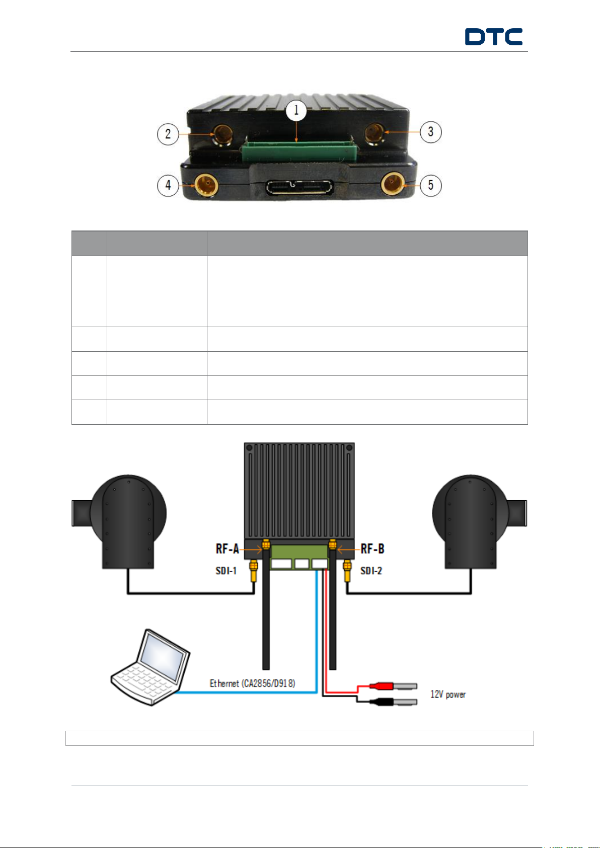
1
34-way header
1. Connect D1804 breakout PCB.
2. Connect J4 (ETHERNET) to a PC or network Ethernet port via CA2856
and D918.
3. Connect J2 (PWR) to 12V power via CA3043.
2
SMP 50 ohm jack
RF-A COFDM antenna.
3
SMP 50 ohm jack
RF-B COFDM antenna.
4
MCX jack
SDI-1 video input.
5
MCX jack
SDI-2 video input.
CAUTION: The SOL8SDR-C will need consideration for heatsinking or fan cooling as part of the installation.

SOL8SDR-C Quick Start Guide
Revision 1.0
Page 2
The SOL8SDR-C IP address can be established using DTC’s Node Finder application.
If DHCP settings need to be disabled and a fixed address applied, right click on the device to reconfigure.
Double click the device on Node Finder to open web browser communications.
On authentication, leave the Username blank and enter the Password as Eastwood.
Go to the Configuration>Preset>Encoder tab and set the Video Source and Format to match the attached
camera. Click Apply at the bottom of the page to save the settings.
Go to the Configuration>Preset>Modulator tab and make the settings for your system, highlighted below.
Click Apply at the bottom of the page to save the settings. These settings must be matched at the receiver.
 Loading...