

Page 1

Document Number DS000034
User Manual
NETNode
Phase 1 and 2 Units (software versions >V2.1)
Cobham Surveillance
Unclassified
The Cobham Centre - Solent
Fusion 2
1100 Parkway
Solent Business Park
Whiteley
Hampshire
PO15 7AB
+44 (0)1489 566 750
Page 2

NETNode
Phase 1 and 2 Units
NETNode
User Manual
NETNode-V2.3 i DS000034 Unclassified
0. Preface
0.1. About this Document
This manual describes the operation of domo IP radio MESH systems. The manual is
divided into three main sections.
Getting started and basic operation
This section describes to users how to deploy and use a domo IP Radio MESH system with
its associated NETNode units in typical operational scenarios.
Advanced operation
This section describes the operation of the system in more detail, concentrating particularly
on secondary functions such as importing mapping information and working with
configurations.
Technical reference
This section provides technical specification and control protocol data and will be of interest
to those integrating the MESH system into larger systems.
0.2. Who Should Read this Book
This document is meant for anyone interested in how the system can best be used, but it is
of most benefit to:
Operators, who are in charge of the daily operation of the systems and infrastructure.
0.3. Assumed Knowledge
Throughout this book it is assumed that the reader has a thorough knowledge of:
Web Navigation and Browsers
TCP/IP Network configuration
Page 3

NETNode
Phase 1 and 2 Units
NETNode
User Manual
NETNode-V2.3
ii
DS000034 Unclassified
Typographic Conventions
Convention
Examples
TEXT in small capitals represents a
specific key press on the console
keyboard or hardware panel.
ESC, F1, SHIFT
The + sign means “hold down the first
key while pressing the second key”.
Press CTRL+C to abort
<Text> Serves as a placeholder for
variable text that you will replace as
appropriate to its context.
Use the filename
<systemname>.sys for…
Text in bold emphasises a new word or
term of significance.
We call this a protocol
and its function is…
[-a] Text in these brackets indicates an
optional component that can be left out.
Ls [-a]
NN This indicates a value entered on a
numeric keypad.
45 on the numeric
keypad
Successive menu selections are
shown using arrows to indicate a submenu. In this example this would mean:
Select the Insert menu, then select
picture, then select from file.
Insertpicturefrom
file
0.4. Typographic Conventions
This document uses these typographic conventions to identify text that has a special
meaning:
0.5. Symbols
This document uses these symbols to highlight important information:
WARNING: A written notice given to a reader when a situation might result in personal
injury or loss of life.
CAUTION: A written notice given when a situation might result in damage to or destruction
of equipment or systems.
NOTE: A written notice given to draw the reader‟s attention to something or to supply
additional information.
Page 4

NETNode
Phase 1 and 2 Units
NETNode
User Manual
NETNode-V2.3
iii
DS000034 Unclassified
Document
Source
None
Revision
Date
Authors
Summary of Changes
V1.4
2009-12-18
NMcS / RC
New format
V1.5
2009-12-24
CB
Add new features
V1.8
2010-10-18
CB
Updates for V2.1 release
V1.9
2010-10-00
CB
Updates
V2.0
2011-05-23
RDPC
Address, FCC compliance
V2.1
2011-09-30
RDPC
More Compliance statements
V2.2
2011-10-18
SD
Intrinsic Safety inclusion.
V2.3
2011-12-12
SD
FCC 15.19 Statement.
0.6. Trademarks
All trademarks or registered trademarks that appear in this document are the property of
their respective owners.
0.7. Related Documents
You may also need to read:
0.8. Document History
This document was written and produced by Cobham Technical Communications Team.
This is a change controlled document. Each main page of this document displays a file name
at the bottom left corner of the page. This is followed by a release number („V1.0‟ is the
original). The revision date is also indicated in the table below.
Changes to any page will raise the revision status of the whole document.
Page 5

NETNode
Phase 1 and 2 Units
NETNode
User Manual
NETNode-V2.3
iv
DS000034 Unclassified
Contents
0. Preface ......................................................................................... i
0.1. About this Document ........................................................................................ i
0.2. Who Should Read this Book ............................................................................... i
0.3. Assumed Knowledge ......................................................................................... i
0.4. Typographic Conventions ................................................................................. ii
0.5. Symbols.......................................................................................................... ii
0.6. Trademarks ................................................................................................... iii
0.7. Related Documents ........................................................................................ iii
0.8. Document History ........................................................................................... iii
Contents ............................................................................................ iii
1. Introduction .............................................................................. 1-1
1.1. MESH Applications ........................................................................................ 1-1
1.2. domo MESH Features.................................................................................... 1-2
2. Getting Started and Basic Operation ........................................... 2-3
2.1. Which Model do I Have? ............................................................................... 2-3
2.2. Phase 1 Unit ................................................................................................ 2-4
2.3. Phase 2 Products .......................................................................................... 2-5
2.3.1. Plain Box Variant .................................................................................... 2-5
2.3.2. Robust Product ....................................................................................... 2-6
2.4. Basic Operating Principles ............................................................................. 2-7
2.5. Getting Started on the Bench (Phase 1 Unit) ................................................. 2-11
2.5.1. Cables and Connections ........................................................................ 2-11
2.6. Establishing Connection to a Node ............................................................... 2-12
2.6.1. Connecting the NETNode to your Computer using Serial (RS232) ............. 2-12
2.6.2. Starting the Control Software ................................................................ 2-13
2.6.3. Connecting the NETNode to your Computer using IP ............................... 2-15
2.7. Web-browser Username and Password ......................................................... 2-16
2.8. DC Power .................................................................................................. 2-18
2.9. Ethernet .................................................................................................... 2-19
2.10. Talkback audio (Phase 2 units only) ............................................................. 2-19
2.11. Video and Audio Input (if Option is Present) ................................................. 2-19
2.12. Antennas ................................................................................................... 2-20
2.13. Deploying the System ................................................................................. 2-21
2.13.1. Installation Notes ................................................................................. 2-21
2.13.2. Fixed position Applications .................................................................... 2-21
2.13.3. Vehicle Applications .............................................................................. 2-21
2.13.4. Diversity and Antenna Positioning .......................................................... 2-22
2.14. Battery / DC Power Considerations ............................................................... 2-23
3. Operation ................................................................................ 2-24
3.1. Connecting Up the NETNode ....................................................................... 2-24
Page 6

NETNode
Phase 1 and 2 Units
NETNode
User Manual
NETNode-V2.3 v DS000034 Unclassified
3.1.1. Connecting the Antennas ...................................................................... 2-24
3.1.2. Connecting to AC Supply ....................................................................... 2-24
3.1.3. Connection to DC Supply – Mesh Phase 1 & Phase 2 Robust Unit.............. 2-24
3.2. Starting Up and Shutting Down the NETNodes .............................................. 2-25
3.2.1. Powering up the NETNodes ................................................................... 2-25
3.2.2. Shutting Down the NETNodes ................................................................ 2-25
3.3. Basic Operation .......................................................................................... 2-26
3.3.1. About Enable Check Box ....................................................................... 2-28
3.3.2. About Frequency .................................................................................. 2-28
3.3.3. About Channel Bandwidth ..................................................................... 2-28
3.3.4. About Mesh ID ..................................................................................... 2-28
3.3.5. About Node ID ..................................................................................... 2-28
3.4. Connecting an IP Device to a NETNode ........................................................ 2-29
3.5. Connecting a Second IP Device to a NETNode .............................................. 2-30
3.6. Viewing a Network Camera ......................................................................... 2-31
3.7. Connecting a Composite Camera to a NETNode ............................................ 2-32
3.7.1. Integrated Video Encoding AVI option fitted (Composite Input) ................ 2-32
4. Advanced Procedures ............................................................... 2-34
4.1. Status Tab – Overview Pane ........................................................................ 2-34
4.1.1. Node ID ............................................................................................... 2-34
4.1.2. Unit Name ........................................................................................... 2-34
4.1.3. IP Address ........................................................................................... 2-34
4.1.4. Battery Voltage .................................................................................... 2-34
4.1.5. Show Details Check Box ........................................................................ 2-35
4.1.6. Signal Quality ....................................................................................... 2-36
4.1.7. SNR ..................................................................................................... 2-36
4.1.8. Level A ................................................................................................ 2-36
4.1.9. Level B ................................................................................................ 2-36
4.1.10. IP Rx Errs ............................................................................................ 2-37
4.2. Status Tab – Spectra Pane .......................................................................... 2-38
4.2.1. About the Spectra Displays .................................................................... 2-38
4.2.2. Interference ......................................................................................... 2-38
4.3. Status Tab – Maps Pane .............................................................................. 2-39
4.3.1. Radio Buttons ...................................................................................... 2-39
4.3.2. Node Information ................................................................................. 2-39
4.3.3. GPS Information ................................................................................... 2-39
4.3.4. Show Details Check Box ........................................................................ 2-40
4.3.5. Network Display ................................................................................... 2-40
4.3.6. Map Display ......................................................................................... 2-41
4.3.7. Manual Placement ................................................................................ 2-41
4.3.8. GPS Placement ..................................................................................... 2-42
4.3.9. Upload Map Data .................................................................................. 2-42
4.4. Global Settings Tab .................................................................................... 2-45
4.4.1. Unit Name ........................................................................................... 2-45
4.4.2. Control/Data Port ................................................................................. 2-45
4.4.3. Auxiliary Address .................................................................................. 2-46
4.4.4. Relay Only ........................................................................................... 2-47
4.4.5. Speed Units ......................................................................................... 2-47
4.4.6. Streaming Protocol ............................................................................... 2-47
4.4.7. DHCP Enable ........................................................................................ 2-47
Page 7

NETNode
Phase 1 and 2 Units
NETNode
User Manual
NETNode-V2.3
vi
DS000034 Unclassified
4.4.8. IP Address ........................................................................................... 2-47
4.4.9. Network Mask ...................................................................................... 2-48
4.4.10. Gateway .............................................................................................. 2-48
4.4.11. Update All Nodes .................................................................................. 2-48
4.4.12. Setting the clock (Phase 2 units only) ..................................................... 2-49
4.4.13. Format File System… ............................................................................ 2-49
4.4.14. Restore Defaults… ................................................................................ 2-50
4.4.15. Change Password… .............................................................................. 2-51
4.5. Configuration Tab – Transmitter Pane .......................................................... 2-52
4.5.1. Preview and Active Configuration ........................................................... 2-52
4.5.2. Enable Transmitter Check Box ............................................................... 2-53
4.5.3. Frequency ............................................................................................ 2-53
4.5.4. Channel Bandwidth ............................................................................... 2-53
4.5.5. Output Level High and Output Level Low ................................................ 2-53
4.5.6. Output Level Select .............................................................................. 2-53
4.6. Configuration Tab – Mesh Pane ................................................................... 2-54
4.6.1. Mesh ID ............................................................................................... 2-54
4.6.2. Node ID ............................................................................................... 2-54
4.6.3. IP Forward ........................................................................................... 2-54
4.7. Configuration Tab – Streamer Pane .............................................................. 2-54
4.7.1. Source Mask ........................................................................................ 2-55
4.7.2. Destination Mask .................................................................................. 2-56
4.7.3. Multicast Address ................................................................................. 2-56
4.7.4. SAP Address ......................................................................................... 2-57
4.7.5. Port ..................................................................................................... 2-57
4.7.6. Service Name ....................................................................................... 2-57
4.8. Configuration Tabs – Data RS232/RS485 Pane .............................................. 2-57
4.8.1. Data Mode ........................................................................................... 2-57
4.8.2. Baud Rate ............................................................................................ 2-58
4.8.3. Parity .................................................................................................. 2-58
4.8.4. IP Port and IP Address .......................................................................... 2-58
4.8.5. GPS Source .......................................................................................... 2-59
4.8.6. IP Data Scrambling ............................................................................... 2-60
4.8.7. Scrambling Key .................................................................................... 2-60
4.9. Configuration Tab – Record Pane ................................................................. 2-61
4.9.1. File length ............................................................................................ 2-61
4.9.2. Record ................................................................................................. 2-61
4.10. Configuration Tab – Audio Pane ................................................................... 2-61
4.10.1. Mode ................................................................................................... 2-62
4.10.2. Microphone Gain .................................................................................. 2-62
4.10.3. Headphone Gain ................................................................................... 2-62
4.10.4. Mute Level ........................................................................................... 2-62
4.11. Configuation Tab – VLAN Pane 1-8 .............................................................. 2-62
4.11.1. Tag ..................................................................................................... 2-62
4.11.2. IP address ........................................................................................... 2-62
4.11.3. Sub Mask ............................................................................................. 2-62
4.12. Information Tab ......................................................................................... 2-63
4.13. Encoder Tab .............................................................................................. 2-64
4.13.1. Encoder Preset ..................................................................................... 2-64
4.13.2. Video Lock ........................................................................................... 2-64
4.13.3. Audio Enable ........................................................................................ 2-64
Page 8

NETNode
Phase 1 and 2 Units
NETNode
User Manual
NETNode-V2.3
vii
DS000034 Unclassified
4.13.4. Scrambling ........................................................................................... 2-64
4.13.5. Scrambling Key .................................................................................... 2-65
5. Streaming over IP .................................................................... 5-66
5.1. General Info............................................................................................... 5-66
5.2. Multicast Streaming .................................................................................... 5-66
5.2.1. Streamer Operation .............................................................................. 5-66
5.2.2. Configuration Tab – Streamer Pane (Multicast Mode) ............................... 5-66
5.3. RTSP Streaming ......................................................................................... 5-69
5.4. Stream Recording and playback (v2.1) ......................................................... 5-69
5.4.1. Formatting ........................................................................................... 5-70
5.4.2. Recording ............................................................................................ 5-70
5.4.3. Playing back the recorded data .............................................................. 5-71
5.4.4. Transferring the files ............................................................................. 5-71
6. Configuring your NETNode for GPS ............................................ 6-72
6.1. General Information ................................................................................... 6-72
6.2. Connecting the GPS unit to the NETNode ..................................................... 6-72
6.2.1. 8-Way Garmin Plug (female) Pin Out ...................................................... 6-73
6.2.2. 15-Way High Density D-Type Plug (male) Pin Out ................................... 6-74
6.3. Configuring NETNode for GPS ...................................................................... 6-75
6.3.1. Displaying GPS location on map ............................................................. 6-77
7. VLAN Support (v2.4) ................................................................. 7-78
7.1. Configuring VLAN ....................................................................................... 7-78
7.2. Setting VLAN tagging and stripping on External ports .................................... 7-78
7.2.1. VLAN tagging ....................................................................................... 7-79
7.2.2. VLAN stripping ..................................................................................... 7-79
8. Interlink Mode .......................................................................... 8-81
8.1. Operation .................................................................................................. 8-81
8.2. Configuring Interlink Mode .......................................................................... 8-82
9. Mission Commander ................................................................. 9-84
10. LED Indicators ..................................................................... 10-85
10.1. NETNode Phase 1 Unit .............................................................................. 10-85
10.1.1. Top Led ............................................................................................. 10-85
10.1.2. Bottom Led ........................................................................................ 10-85
10.2. NETNode Phase 2 Robust Unit ................................................................... 10-85
10.3. NETNode Phase 2 Plain Box Unit ................................................................ 10-86
11. Connector Pin Outs (Phase 1) ............................................... 11-87
11.1. POWER – 2-way Female Amphenol Male Size 10 ......................................... 11-87
11.2. CTRL / DATA 19-way Female Amphenol Size 14 .......................................... 11-87
11.3. IP 4-way Female Amphenol Size 08............................................................ 11-87
11.4. AV 10-way Female Amphenol Size 12 ......................................................... 11-88
Page 9

NETNode
Phase 1 and 2 Units
NETNode
User Manual
NETNode-V2.3
viii
DS000034 Unclassified
12. Connector Pin Outs (Phase 2 Plain Box) ................................ 12-89
12.1. AV - 4-pin 0B LEMO Socket (TX and RX) ..................................................... 12-89
12.2. Data - 3-pin 0B LEMO Socket..................................................................... 12-89
12.3. Aux 15-way Female High Density D-Type ................................................... 12-90
12.4. RJ45 1 and 2 ............................................................................................ 12-90
12.5. A/V Input - 5-pin 0B LEMO socket (Only with A/V option) ............................ 12-90
12.6. T/B - 6-pin 0B LEMO socket (G-key) ........................................................... 12-91
12.7. RF Connectors .......................................................................................... 12-91
13. Phase 2 Robust Unit ............................................................ 13-92
13.1. Power Amphenol 38999 Series 3 11-98 6 way chassis plug .......................... 13-92
13.2. Camera Connector Amphenol 38999 Series 3 15-19 19 way chassis socket .... 13-92
13.3. Misc Connector Amphenol 38999 Series 3 13-35 22 way chassis socket ........ 13-93
13.4. RF Connectors .......................................................................................... 13-93
14. Control Protocols ................................................................. 14-94
15. Default Configurations ......................................................... 15-95
15.1. Default IP Address .................................................................................... 15-95
16. NETNode Specification ......................................................... 16-96
17. Warranty and Support ......................................................... 17-98
17.1. Warranty Cover ........................................................................................ 17-98
18. Safety, Compliance and Approvals ........................................ 18-99
18.1. Safe Operating Procedures ........................................................................ 18-99
18.2. EMC / Safety and Radio Approvals ............................................................. 18-99
18.3. CE marking .............................................................................................. 18-99
Page 10

NETNode
Phase 1 and 2 Units
NETNode
User Manual
NETNode-V2.3
1-1
DS000034 Unclassified
1. Introduction
Cobham Surveillance domo has been supplying point to point high data rate digital video
links for many years to security users. These links exhibit exceptional performance, enabling
users to reliably exchange video data in extremely difficult RF transmission environments
such as mobile links and links in dense urban areas. More recently domo has seen an
increasing requirement to use the rugged transmission capabilities of COFDM to carry
general purpose IP traffic.
There is now also a growing demand from domo customers to incorporate bi-directional
capability in its solution, and also a MESH capability.
The traditional two frequency approach (Frequency Division Duplex or FDD) to enable bidirectionality is not convenient or appropriate in many applications; the use of separate
frequencies makes frequency management difficult. Also FDD adds complexity, cost and
weight with additional antennas, amps and circuitry.
The solution to this problem is a single frequency approach (Time Division Duplex or TDD)
where all communicating nodes share the same frequency. This simplifies frequency
management and circuitry implementation.
1.1. MESH Applications
Rapid deployment temporary surveillance
Mini and Micro UAV communications.
Radios to connect surveillance team vehicles.
Special Forces data radios.
Military vehicle radios.
True real time surveillance / pursuit where an ad-hoc network is used relay imagery in a
fluid environment. This would apply equally to manned surveillance as to vehicle pursuit.
Next generation Unmanned Ground Vehicles (UGVs) where vehicles operate co-
operatively.
FIST battlefield communication applications.
Perimeter security applications.
Each MESH NETNode has two Ethernet interfaces to allow flexibility of connection. This, in
conjunction with the radio link, provides the same functionality as a switched Ethernet hub.
The radio technology is based on the fundamentals of the acclaimed domo Solo4 rugged,
robust and reliable transmission system giving an extremely secure and easily deployable bidirectional communication system.
AES BCRYPT1 encryption/decryption (AES128 & 256) is also supported on both forward and
reverse paths of the MESH system. AES support is an optional software feature and may
require an export license.
Page 11

NETNode
Phase 1 and 2 Units
NETNode
User Manual
NETNode-V2.3
1-2
DS000034 Unclassified
1.2. domo MESH Features
Single frequency IP MESH Network
Reduces antennas, amplifiers, filters in a bi-directional unit
No central Node (genuine Mesh)
No single point of failure
Makes a very adaptable
Rapid connection and disconnection
Nodes are able to connect into the network within 2 seconds without user
intervention
8 Nodes Maximum
8 nodes provides a good balance between capacity and latency
Very rugged RF link
Proven to be 5 to 10 times better than Wi-Fi per link
IMPORTANT NOTE:
The MESH IP Radio product range has been specifically designed for government security
and law enforcement users, the equipment will tune across frequencies that are only
available to licensed government users. Non-government users should employ the
equipment restricted to the license exempt bands only typically 1.389 to 1.399GHz, 2.400 to
2.483GHz and 5.725 to 5.875GHz.
Page 12

NETNode
Phase 1 and 2 Units
NETNode
User Manual
NETNode-V2.3
2-3
DS000034 Unclassified
domo
NETNode1W-217250
Made in the UK
2. Getting Started and Basic Operation
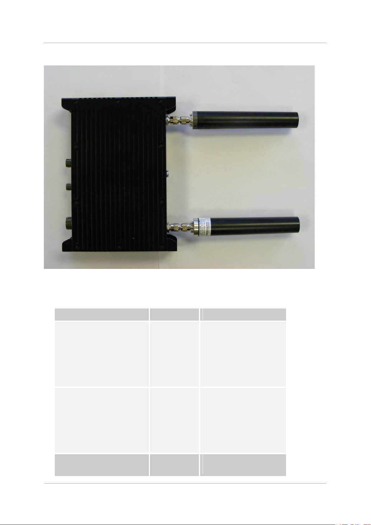
2.1. Which Model do I Have?
Each unit in the domo product range is marked with two panels.
Product Code Panel. Give product code and manufacturers information.
CE and Serial Number Panel. Gives CE mark and product serial number.
Mesh systems are available in 3 different product enclosures. These enclosures are targeted
to different user applications.
Phase 1 units are sold in waterproof milled aluminium boxes suitable for outdoor mounting.
Phase 2 units supersede the Phase 1 units. These are made in two variants; a plain box
variant and a waterproof robust box variant. The plain box variant uses standard cable and
connectors where possible. The robust variant is a milled aluminium enclosure and uses
Amphenol connectors and bespoke Amphenol cables. These bespoke cables are supplied
with the unit.
Page 13
NETNode
Phase 1 and 2 Units
NETNode
User Manual
NETNode-V2.3
2-4
DS000034 Unclassified
Product Code
Product
Accompanying items
NETNode1W-217250
(2.17 to 2.50GHz)
1W RF output
MESH link
(1 node)
Cables:
1-off Control 2m (CA288)
1-off DC Power 5m (CA285)
1-off Ethernet 5m (CA284)
CD with operating software and
manual
NETNode1W-550600
(5.5 to 6.0GHz)
1W RF output
MESH link
(1 node)
Cables:
1-off Control 2m (CA288)
1-off DC Power 5m (CA285)
1-off Ethernet 5m (CA284)
CD with operating software and
manual
NETNode-AVI-UP
Audio/Video Input
option
Fitted inside the
Cables:
1-off A/V cable 2m (CA286)
2.2. Phase 1 Unit
The domo product code can be referenced in the table below.
Page 14
NETNode
Phase 1 and 2 Units
NETNode
User Manual
NETNode-V2.3
2-5
DS000034 Unclassified
NETNode
Product Code
Product
Accompanying items
NETNode-P-217250
(2.17 to 2.50GHz)
1W RF output
MESH link
(1 node)
Cables:
1-off Control 2m (CA0001)
1-off DC Power brick (CA0023)
1-off Auxiliary cable(CA0474)
NETNode-P-115140
1W RF output
Cables:
Note: Antennas are not included with this product.
2.3. Phase 2 Products
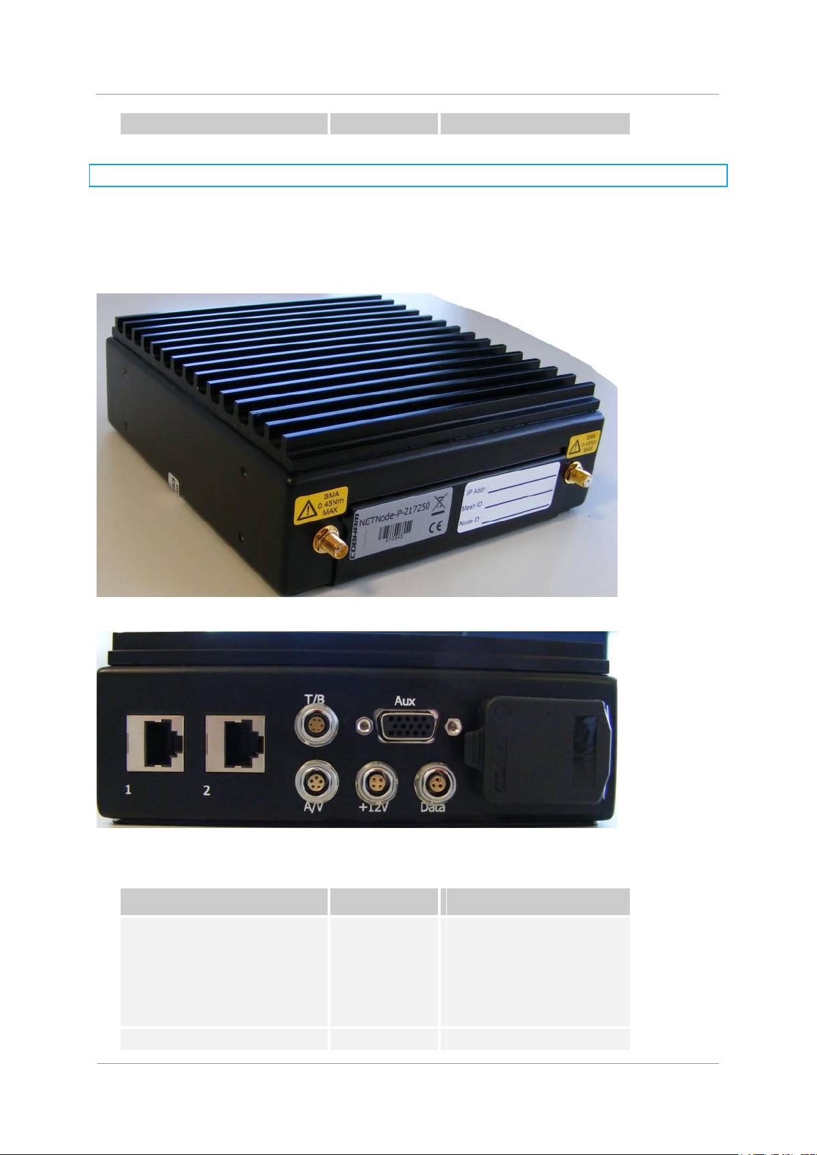
2.3.1. Plain Box Variant
The domo product code can be referenced in the table below.
Page 15
NETNode
Phase 1 and 2 Units
NETNode
User Manual
NETNode-V2.3
2-6
DS000034 Unclassified
(1.15 to 1.40GHz)
MESH link
(1 node)
As NetNode-P-217250
NETNode-P-034047
(340 to 470MHz)
1W RF output
MESH link
(1 node)
Cables:
As NetNode-P-217250
NETNode-P-440500
(4.40 to 5.00GHz)
1W RF output
MESH link
(1 node)
Cables:
As NetNode-P-217250
NETNode-AVI-UP2
Audio/Video Input
option for Phase 2
Fitted inside the
NETNode
Cables:
1-off A/V cable 2m (CA0122)
Product Code
Product
Accompanying items
NETNode-R-217250
(2.17 to 2.50GHz)
1W RF output
MESH link
(1 node)
Cables:
1-off Control/Data 2m (CA406)
1-off DC/Ethernet 5m (CA403)
Note: Antennas are not included with this product.
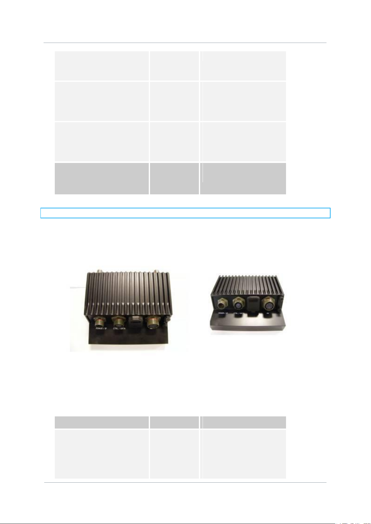
2.3.2. Robust Product
The domo product code can be referenced in the table below.
Page 16
NETNode
Phase 1 and 2 Units
NETNode
User Manual
NETNode-V2.3
2-7
DS000034 Unclassified
NETNode-R-115140
(1.15 to 1.40GHz)
1W RF output
MESH link
(1 node)
Cables:
As NetNode-R-217250
NETNode-R-034047
(340 to 470MHz)
1W RF output
MESH link
(1 node)
Cables:
As NetNode-R-217250
NETNode-R-440500
(4.40 to 5.00GHz)
1W RF output
MESH link
(1 node)
Cables:
As NetNode-R-217250
NETNode-AVI-UP2
Audio/Video Input
option for Phase 2
Fitted inside the
NETNode
Cables:
1-off A/V cable 2m (CA0477)
Node
2
IP PTZ
Camera
IP PTZ Camera
Private
LAN
Node
1
Node
3
Note: Antennas are not included with this product.
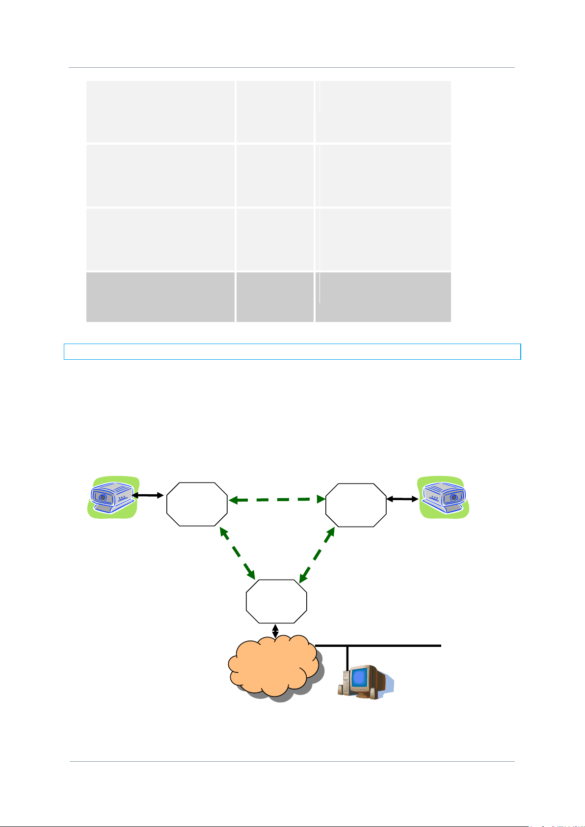
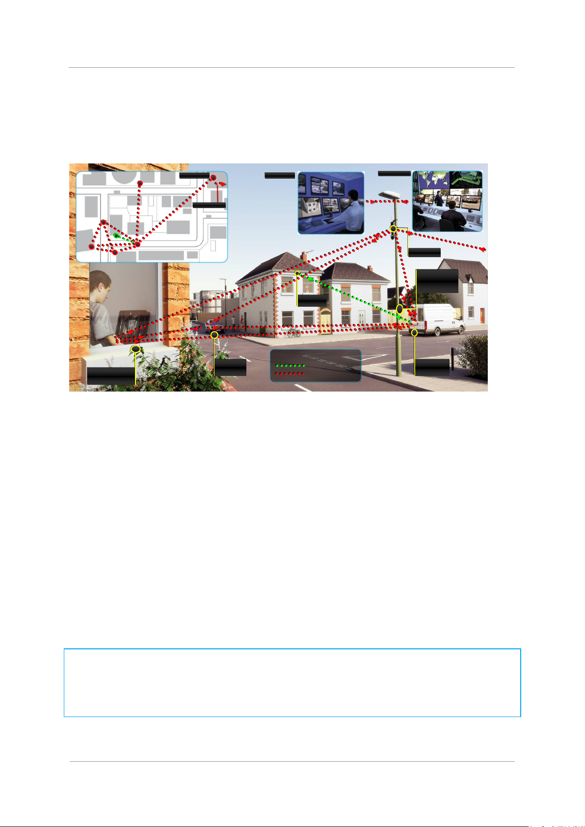
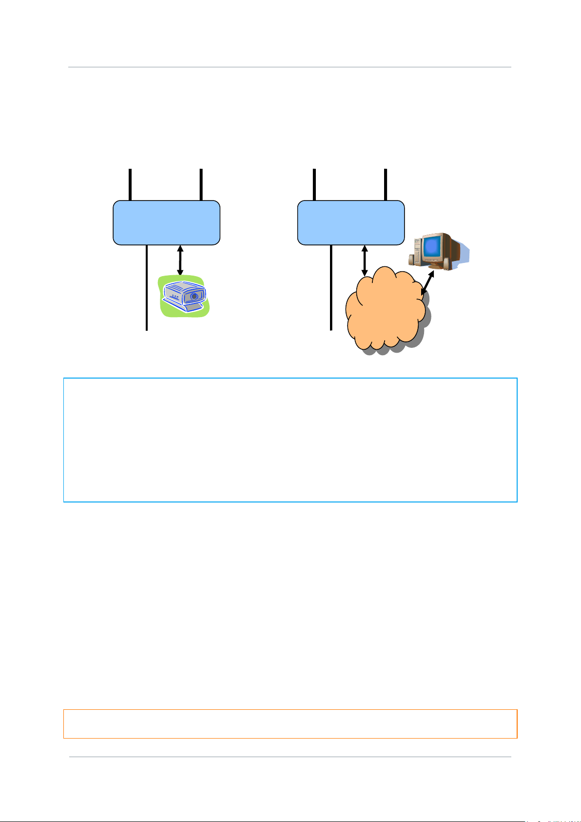
2.4. Basic Operating Principles
As an example a basic system is illustrated with two IP cameras contributing into a Private
LAN using the MESH system. Each MESH NETNode behaves as a switched hub providing two
physical Ethernet ports, and a connection onto the mesh radio link.
All NETNode units are connected to each other as a wireless IP network. The Mesh system
arbitrates which node transmits at any given time avoiding any conflict.
Page 17

NETNode
Phase 1 and 2 Units
NETNode
User Manual
NETNode-V2.3
2-8
DS000034 Unclassified
The nodes are able to seamlessly connect into the network without user intervention. The
only key parameters that need to be preloaded into the units are the encryption keys and
the frequency.
Page 18
NETNode
Phase 1 and 2 Units
NETNode
User Manual
NETNode-V2.3
2-9
DS000034 Unclassified
Key
SOLO system
Mesh system
SOLO
Transmitter
Tactical
monitoring
Camera Car
Mobile
surveillance
Camera
Camera
Behind house
Police command
Police command
Central command
Central command
Mesh could also be used to quickly deploy a multiple node surveillance system around an
area of interest. The NETNode units could be used to contribute Video or IP data such as
stills photography or sensor data.
The NETNode can accept video from a standard composite (PAL/NTSC) camera or an IP
camera can be connected through the MESH Network. To connect a standard composite
video signal into a MESH NETNode the NETNode-AVI-UP option must be fitted into the
NETNode.
The MESH is able to support 3 or 4 full quality video links through the one frequency – if 3
nodes were to contribute video simultaneously then the bit-rate for each link would have to
be adjusted to roughly 700kbps per video service. Full frame rate video can be supported at
700kbps but at reduced resolution – typically ½ resolution or SIF resolution would be
selected. Higher resolutions could also be supported – even up to full resolution but typically
not at full frame rate.
A 4 or 5 Node Mesh network (when configured to operate in 3.5MHz bandwidth mode) can
have up to 3Mbps of data capacity available for transmission of information between the
Nodes IF every Node can see every other Node and the link quality between all the nodes is
good. Note that if information needs to be transmitted through a chain of Nodes or if the link
quality is not good then the useful information rate available in the Mesh reduces.
NOTE: Some Phase 2 Mesh Nodes (4.4 to 5GHz) units and post Sep 2010 delivery (2.17 to
2.50GHz) Mesh NETNodes can support a 5MHz bandwidth that allows up to 5.5Mbps of
useable data in the Mesh Network. To discover if your unit supports 5MHz bandwidth you
can look at the Board Type in the Information Pane of the web browser interface. See
Section 4.12 Information Tab for details on how to discover the Board Type.
Page 19
NETNode
Phase 1 and 2 Units
NETNode
User Manual
NETNode-V2.3
2-10
DS000034 Unclassified
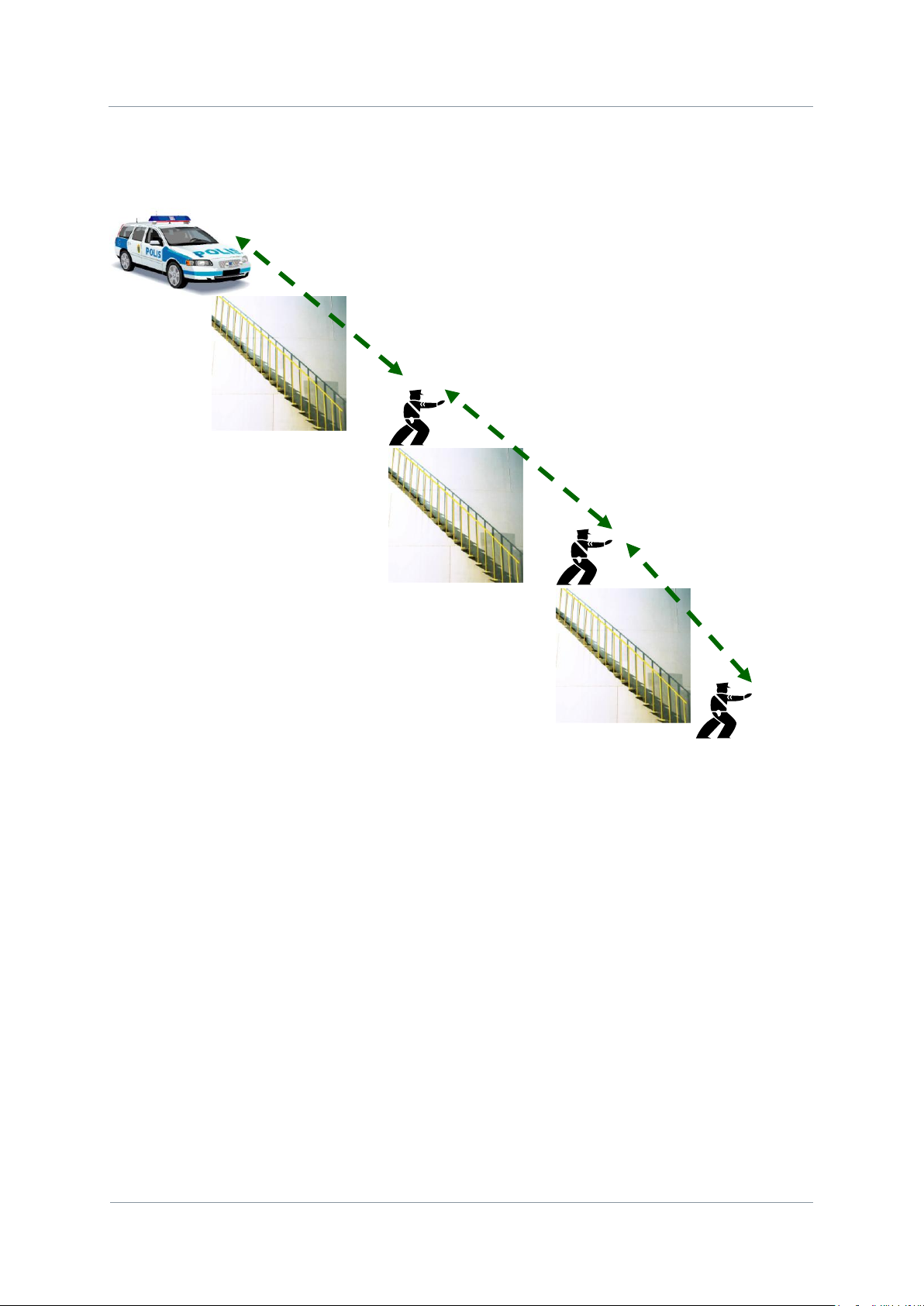
The MESH can also be used to facilitate range extension. Nodes can communicate through a
chain.
In this example the MESH system is used to provide a video link back through a chain to a
command vehicle. Using either the Talkback feature (Phase 2 NETNodes) or an external
VOIP codec all the operatives could also be listening and communicating over the network.
Page 20
NETNode
Phase 1 and 2 Units
NETNode
User Manual
NETNode-V2.3
2-11
DS000034 Unclassified
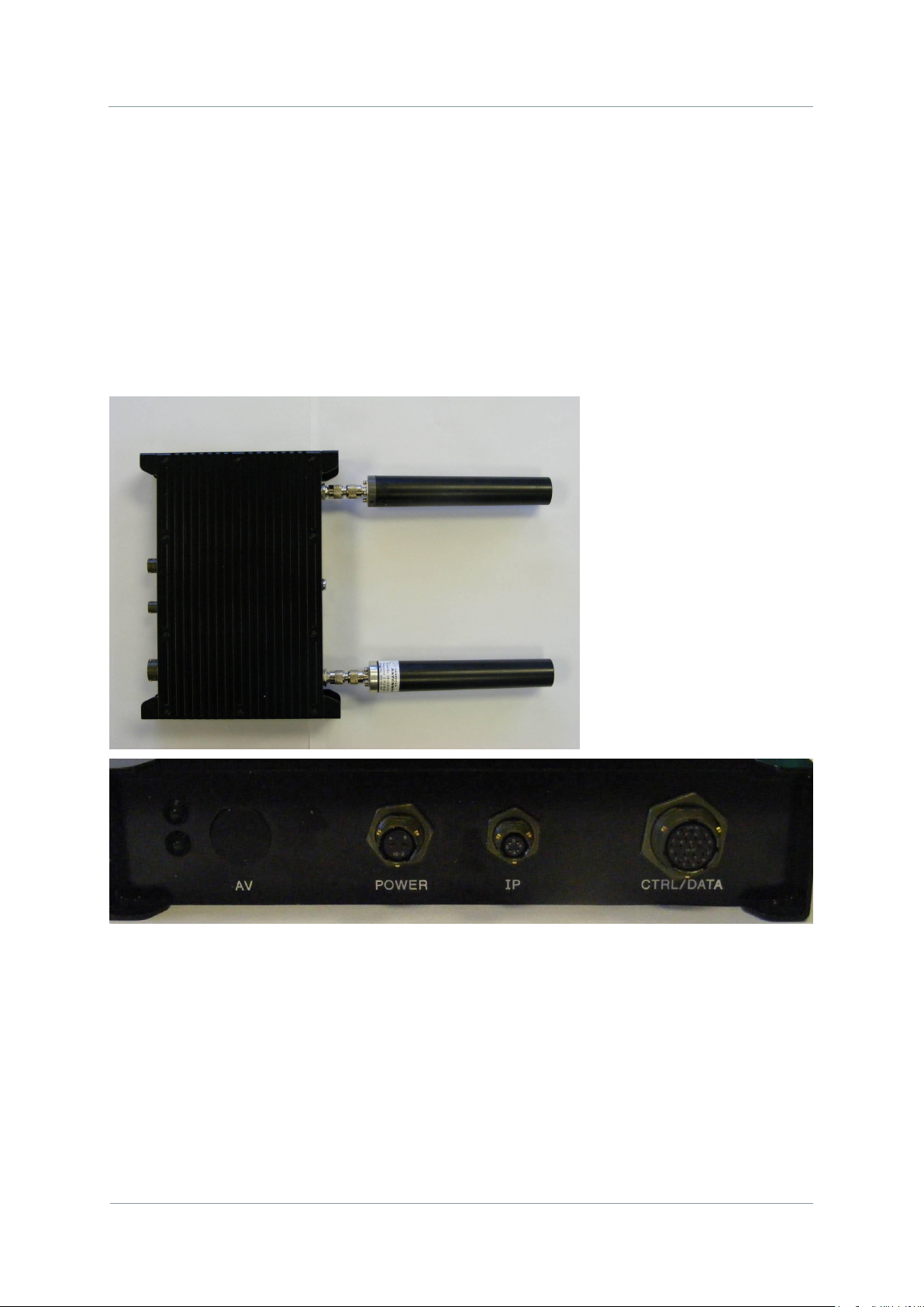
2.5. Getting Started on the Bench (Phase 1 Unit)
2.5.1. Cables and Connections
This section describes how to connect the following domo model numbers.
NETNodeIP1W-217250 (2.17 to 2.50GHz)
NETNode-AVI-UP (option)
The pictures below show the Phase1 domo NETNode product.
A domo MESH Phase 1 NETNode and a Phase 2 Plain box NETNode is supplied with the
following cables:
IP via Ethernet x 1
Control 2m x1
DC Power 5m x1
AV 2m x1 (if the NET-AVI-UP option is ordered)
Page 21

NETNode
Phase 1 and 2 Units
NETNode
User Manual
NETNode-V2.3
2-12
DS000034 Unclassified
A domo MESH Phase 2 Weatherproof NETNode is supplied with the following cables:
IP via Ethernet x 1 and DC Power is combined Part Number CA0403
Control 2m x1 Part Number CA0406
AV 2m x1 (if the NET-AVI-UP2R option is ordered) Part Number CA0477
A domo MESH Phase 2 Plain NETNode is supplied with the following cables:
Standard 12V Power Block Part Number CA0023
Control cable 2m x1 Part Number CA0001
Special Control / Data Cable Part number CA0474
AV 2m x1 (if the NET-AVI-UP2P option is ordered) Part Number CA0122
Before deploying domo MESH NETNode units in the field it is strongly advised to test the
products in a bench environment in order to gain familiarity with the product.
BEFORE SWITCHING ON THE UNIT PLEASE NOTE:
The DC power supply must be set to 12.5V and assume up to 2.5A of current draw.
2.6. Establishing Connection to a Node
Once a user has connected to a unit and established a NETNode on their network operating
the system is easy.
The procedure to establish communication with a node varies depending on whether the
User wishes to connect the MESH to a network running DHCP or whether the user wishes to
run with static IP addresses.
If your network has no DHCP server you will need to assign a fixed IP address for the
NETNode using a serial RS232 interface. If you have a DHCP server the NETNode will
automatically acquire an IP address and you can connect straight via IP. You may still wish
to change the DHCP IP address to a fixed IP address using the browser.
2.6.1. Connecting the NETNode to your Computer using Serial (RS232)
The first time you set up a NETNode with no DHCP you‟ll be connecting using a serial RS232
interface.
You‟ll only have to do this once – every other time you‟ll hook up to the NETNode using an
IP interface using a web browser.
On a Phase 1 Unit
1. Connect the Amphenol 19-way plug (m) from CA0288-5 cable to the Amphenol 19-way
jack (f) on the NETNode labelled CTRL/DATA.
Page 22

NETNode
Phase 1 and 2 Units
NETNode
User Manual
NETNode-V2.3
2-13
DS000034 Unclassified
2. Now, connect the RS232 D-Type 9-way plug (f) to your computer‟s RS232 9-way jack
(m).
Caution: There are two D-Type 9-way plugs on the CA0288-5 cable – ensure you select the
RS232 version by checking the label attached to the shell of the plug. The other is RS485.
On a Phase 2 Robust Unit
3. Connect the Amphenol plug (m) from CA0406 cable to the Amphenol jack (f) on the
NETNode labelled CTRL/DATA.
4. Now, connect the RS232 D-Type 9-way plug (f) to your computer‟s RS232 9-way jack
(m).
5.
Caution: There are two D-Type 9-way plugs on the CA0406 cable – ensure you select the
RS232 version by checking the label attached to the shell of the plug. The other is RS485.
On a Phase 2 Plain box Unit
6. Connect the 15-way HD D-Type plug (m) from CA0474 cable to the 15-way D-Type jack
(f) on the NETNode labelled AUX.
7. Now, connect the RS232 D-Type 9-way plug (f) to your computer‟s RS232 9-way jack
(m).
8.
Caution: There are two D-Type 9-way plugs on the CA0474 cable – ensure you select the
RS232 version by checking the label attached to the shell of the plug. The other is RS485.
2.6.2. Starting the Control Software
The procedure to establish communication with a node varies depending on whether the
network is running a DHCP server or whether the user wishes to run with static IP
addresses.
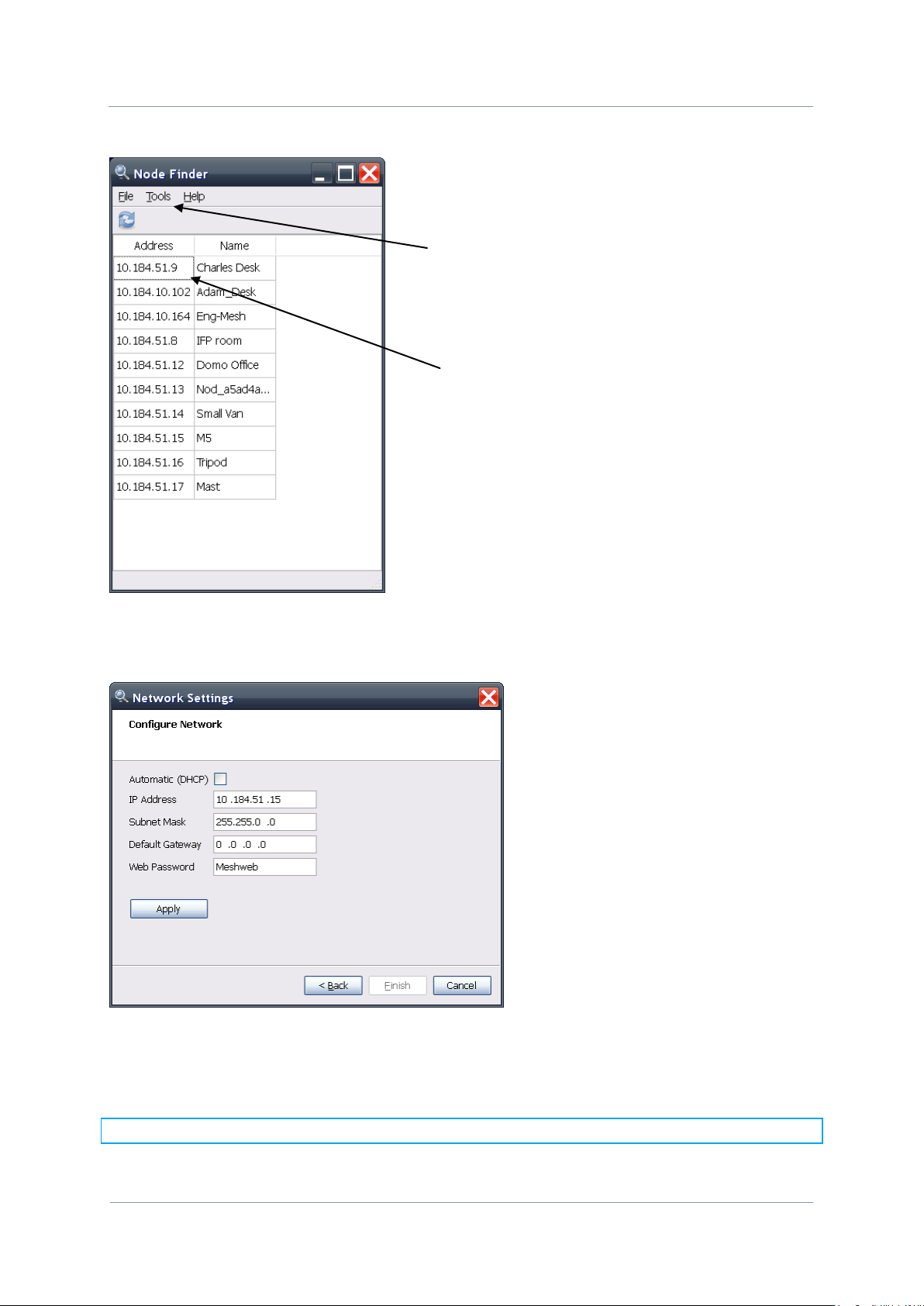
If the network is running DHCP and the NETNode unit is set to defaults, the unit will acquire
an address via DHCP. To find out the IP address a PC running the Node Finder PC application
must be connected to the same network as the Mesh NETNode.
Starting the Nodefinder application will identify the IP address of any and all mesh nodes on
the Network. To find out which unit this is unplug the IP connection to the unit and refresh
Node Finder (F5). The entry that disappears is the node in question.
If the User‟s Network does not support DHCP or the unit has the wrong fixed IP address,
then a PC running the Node Finder PC application must be connected via RS232 using the
data cable (CA288 (Phase1) or CA0406 (Phase 2 Robust) between the port on the PC and
the Control port on the MESH node.
On a Phase2 Plain box Mesh connect the PC to the AUX port using the CA0474 cable. The
RS232 control 9-way D-type must be used.
Page 23
NETNode
Phase 1 and 2 Units
NETNode
User Manual
NETNode-V2.3
2-14
DS000034 Unclassified
Select
Ethernet or
RS232
IP address of
any unit on the
Network
To set the IP address via RS232 select the correct PC RS232 port from the tools->network
setting menu.
If the NETNode unit is connected to a network that supports DHCP then leave the DHCP
option box checked. If the network does not support DHCP then a valid static IP address
must be entered and the DHCP box unchecked.
Note: Click „Apply‟ after changing any configuration setting
Page 24

NETNode
Phase 1 and 2 Units
NETNode
User Manual
NETNode-V2.3
2-15
DS000034 Unclassified
Once a valid IP address is set it may also be changed in the WEB browser.
Now that the IP address is established the web-server should be used to configure frequency
and output power. Once the node is on the User network any Web-browser can be used to
browse to the Mesh NETNode to configure and control the node or to browse network
status. The unit can be browsed by entering the relevant IP address in the web-browser.
2.6.3. Connecting the NETNode to your Computer using IP
For the rest of the set up of the NETNode you‟ll be connecting using an IP interface and a
web browser.
On a Phase 1 Unit
9. Connect the Amphenol 19-way plug (m) from CA0288-5 cable to the Amphenol 19-way
jack (f) on the NETNode labelled CTRL/DATA.
10. Now, connect the RJ45 8-way plug (m) to your computer‟s RJ45 8-way jack (f).
On a Phase 2 Robust unit
11. Connect the Amphenol plug (m) from CA0403cable to the Amphenol jack (f) on the
NETNode labelled Power/IP. (This cable also includes the DC power banana plugs.)
12. Now connect the RJ45 8-way plug (m) to your laptop‟s RJ45 8-way jack (f).
13. Ensure you know the IP address of the computer you have attached.
On a Phase 2 Plain box unit
On a Phase 2 Plain box unit simply connect to one of the RJ45 panel mount sockets labelled
1 or 2 on the NETNode unit. It does not matter which socket you use.
Page 25
NETNode
Phase 1 and 2 Units
NETNode
User Manual
NETNode-V2.3
2-16
DS000034 Unclassified
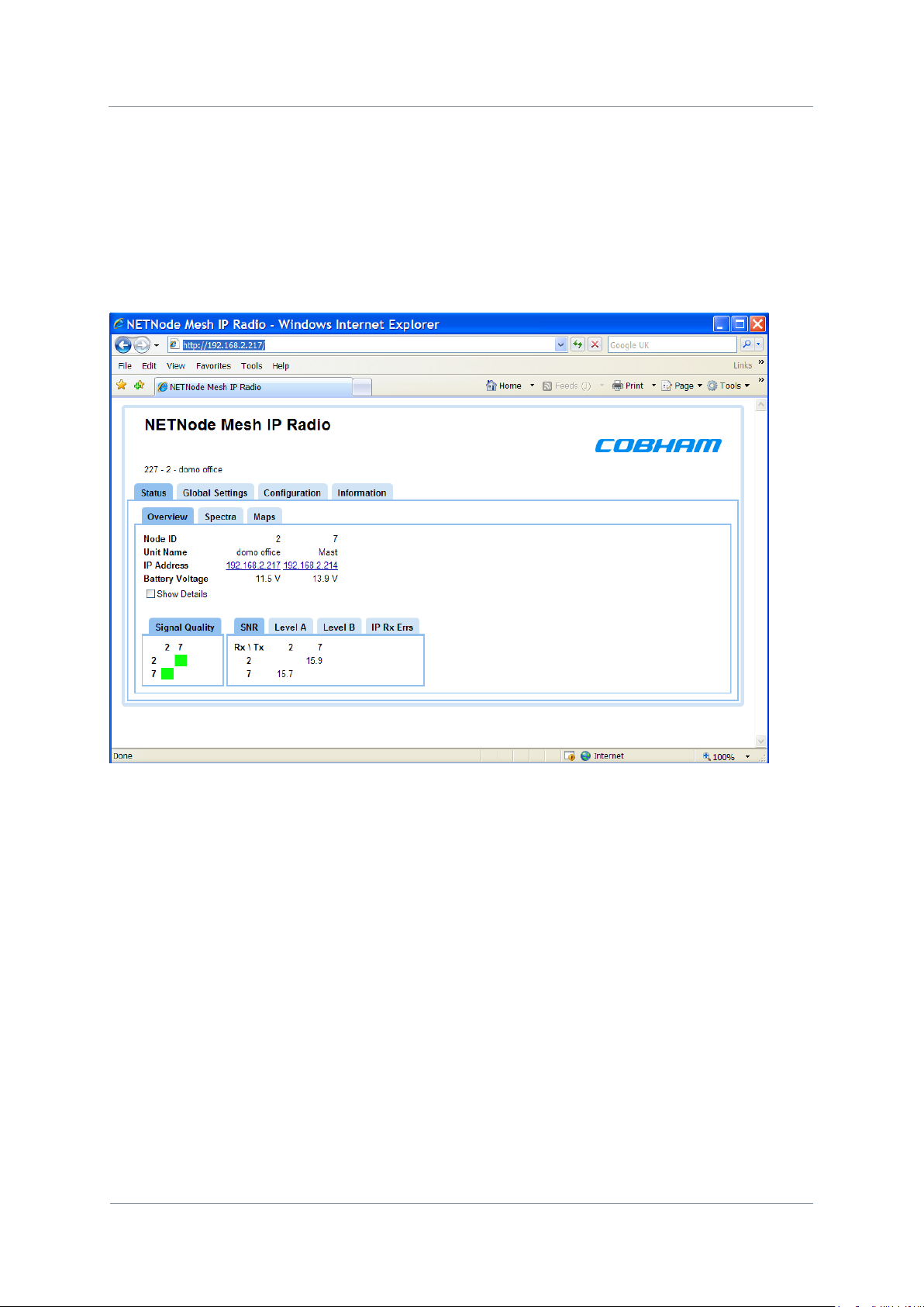
2.7. Web-browser Username and Password
The web-browser will prompt for a Username and Password on the first connection.
Username should be left blank
The default password is „meshweb‟
The status page will be displayed upon successfully entering the Username and Password.
Navigate to the Configuration page by clicking the Configuration Tab.
Page 26
NETNode
Phase 1 and 2 Units
NETNode
User Manual
NETNode-V2.3
2-17
DS000034 Unclassified
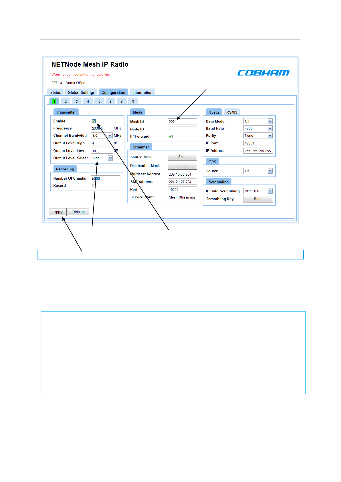
For the units to function in a single network the following must be set correctly:
1. All units must be set to the same frequency
2. All units must have the same channel bandwidth set
3. All units must have their Transmit enabled
4. All units must have the same mesh ID
5. Each unit should be assigned a different node ID (0-7).
6. If encryption is enabled then the encryption type and keys must match.
Mesh
ID
Set Output level select to „Low‟ and set Enable „ON‟ by „ticking‟ the check box.
Note: Click „Apply‟ after changing any configuration setting
Check that the Frequency is valid for the operation of the unit – specific country regulations
will determine the frequencies available for operation. Note that 2400 to 2480MHz is licence
exempt in most of the world.
Page 27
NETNode
Phase 1 and 2 Units
NETNode
User Manual
NETNode-V2.3
2-18
DS000034 Unclassified
Mesh Node
Power
IP
12 Volts
Mesh Node
Power
IP
12 Volts
Private
Power down the Unit.
Repeat the procedure for a second node – making sure that the frequency is always set to
be identical.
Domo suggests configuring the system on the bench as outlined below.
BEFORE SWITCHING ON THE WHOLE SYSTEM PLEASE NOTE:
The DC power must be set to 12.5V and assume up to 2.5A current draw.
Don‟t connect the Ethernet ports of both units simultaneously to your network when they are
both operating as you will create a loop in and out of your IP network. This may affect your
network performance and prevent access to either node for about 1 minute.
Connect one MESH node unit to your network and the other MESH node to an IP camera or
a standalone PC. The IP Camera or the standalone PC will then be connected to your
network through the MESH network.
2.8. DC Power
The NETNode can be powered from a nominal 12V DC supply or an AC to DC adapted
supply.
Locate, push and twist to lock the Amphenol connector on the Power cable into the socket
labelled POWER, taking care to align the connectors. Connect the banana connectors on the
other end of the cable to a suitable DC source.
The 12V DC input has the following characteristics.
Input Voltage Range – 12V to 15V, not reverse voltage protected on Phase 1 Units
Current draw – 1.2A to 2A at 12V (capacity dependant), the power draw is very dynamic
and you should use at least a 2.5A rated supply.
CAUTION: Early units were NOT reverse voltage protected. Take extreme care when
connecting power to this unit. DO NOT OVER VOLTAGE THE UNIT (Use 15V absolute MAX)
Page 28

NETNode
Phase 1 and 2 Units
NETNode
User Manual
NETNode-V2.3
2-19
DS000034 Unclassified
Connector
Signal
Video BNC
75 ohm composite video source, PAL or NTSC
software selectable
Audio Plugs
Line / Microphone level audio, switchable.
Line level -2dBu clip level low impedance
source (< 600 ohm)
Microphone level 12, 24, 36 and 48dB preamp
stages software switchable
2.9. Ethernet
Locate, push and twist to lock the Amphenol connector into the socket labelled „IP‟, taking
care to align the connectors. When using a plain box Mesh Node simply insert a RJ45
network cable into one of the 2 RJ45 Ethernet sockets.
2.10. Talkback audio (Phase 2 units only)
Connect headset to T/B 6-way Lemo.
Microphone power is provided on the audio connectors at approximately 3V (suitable for
Electret microphones)
2.11. Video and Audio Input (if Option is Present)
Locate, push and twist to lock the Amphenol connector into the socket labelled „AV‟, taking
care to align the connectors. If using a plain box Mesh unit simply push fit the Lemo
connector. Connect the video and audio sources.
Microphone power is provided on the audio connectors at approximately 3V (suitable for
Electret microphones)
Typically the video source should be a small colour or black and white CCD camera.
Typically the audio source should be an Electret microphone.
Page 29

NETNode
Phase 1 and 2 Units
NETNode
User Manual
NETNode-V2.3
2-20
DS000034 Unclassified
RF Spec
Model
Number
ending 034047
Model
Number
ending 115140
Model
Number
ending 217250
Model
Number
ending 440500
Model
Number
ending 550600
Output
Frequency
2.170 to 2.50GHz
4.40 to 5.0GHz
5.6 to 5.9GHz
Output
Bandwidth
2.5/3/3.5MHz
2.5/3/3.5MHz
(5MHz)*
2.5/3/3.5MHz
(5MHz)*
2.5/3/3.5/5MHz
2.5/3/3.5MHz
Output Power
1W (nominal)
1W (nominal)
1W (nominal)
0.5W (nominal)
1W (nominal)
Output
Impedance
50 ohm
50 ohm
50 ohm
50 ohm
50 ohm
2.12. Antennas
Note: It is important only to power up the NETNode unit with the Antennas fitted.
Both antennas must be connected for normal operation. The units are supplied with
different types of panel mounted connectors. The phase 1 units are supplied with panel
mounted TNC connectors which carries the RF input and output. The antenna should be
connected by screwing it onto the TNC, but care should be taken to not over tighten the
connector.
The phase 2 plain box mesh units are supplied with panel mounted SMA connectors which
carry the RF input and output. The antenna should be connected by screwing it onto the
TNC, but care should be taken to not over tighten the connector.
The phase 2 robust box mesh units are supplied with panel mounted N-Type connectors
which carry the RF input and output. The antenna should be connected by screwing it onto
the TNC, but care should be taken to not over tighten the connector.
The units have the following RF output characteristics.
* Some later Phase 2 NETNode units at these frequencies can support 5MHz. Units supplied
after November 2010.
Note: It is recommended that the antennas be connected directly to the transmitter unit.
The use of RF cables at this point will degrade the performance of the system.
Page 30

NETNode
Phase 1 and 2 Units
NETNode
User Manual
NETNode-V2.3
2-21
DS000034 Unclassified
Application
Antenna model number
Mobile body worn application
1.00 to 1.40GHz - ANTBCL
2.28 to 2.50GHz - ANTBCS
Mobile vehicle application
1.00 to 1.40GHz – ANT4L
2.20 to 2.50GHz - ANT4S
5.60 to 5.90GHz – ANT4-560590
Long range point to point link
1.00 to 1.40GHz – ANT12L
2.28 to 2.50GHz – ANT12S
5.60 to 5.90GHz – ANT14-560590
The optimum choice of antenna will vary according to application. The following table gives
some suggestions for suitable transmit antennas with the associated domo part number.
Other antennas for more specialist applications, such as aircraft use or covert surveillance
use are available on request from domo.
Some of the antennas will require connector adaptors (Inter series RF adaptors) to connect
the antennas directly to the product.
2.13. Deploying the System
All external connection to the MESH products should be made, as described in the previous
sections, before proceeding to power on the system.
2.13.1. Installation Notes
This section gives guidelines for how to install the MESH node in the following applications.
2.13.2. Fixed position Applications
The Phase 1 and Phase 2 robust NETNode units are designed to be waterproof allowing
them to be installed outdoors.
2.13.3. Vehicle Applications
Interconnection between the unit and any antenna should be kept as short as possible, but
where this is not possible, special attention should be taken to use only low loss cables. An
appropriate cable might be RG213C/U. It is essential to minimise the distance between the
unit and the antenna. Mounting holes are provided.
Power conversion will be required for 24V vehicles.
The video input can be connected across long video cable lengths so remotely mounted
cameras should pose no problem.
The unit is self-cooling; however it should be mounted in a ventilated environment. Forced
air cooling is not required.
Page 31

NETNode
Phase 1 and 2 Units
NETNode
User Manual
NETNode-V2.3
2-22
DS000034 Unclassified
2.13.4. Diversity and Antenna Positioning
The domo MESH NETNode product uses an advanced diversity technique called maximum
ratio combining to construct a good spectrum from two potentially damaged received
signals. This requires a small separation of the antennas.
Sometimes better results can be achieved by separating the antennas further. The optimum
antenna placement depends on the environment in which the equipment is used and the
signal path, and is often limited by physical factors (accessibility for example) as well as
cable loss.
Note: Any cable run between the Node and the antenna MUST be LOW LOSS cable.
Contact domo for details of suitable cable. Note that a cable suitable for use at 400MHz will
not necessarily also be suitable for use at 5GHz.
Page 32

NETNode
Phase 1 and 2 Units
NETNode
User Manual
NETNode-V2.3
2-23
DS000034 Unclassified
2.14. Battery / DC Power Considerations
The Phase 1 MESH NETNode units can consume over 2A of current at 12V. Phase 2
NETNodes typically do not exceed 1.5Amps of current consumption at 12V nominal supply
voltage.
They are designed to trip off at 10.5V and reset on at 11.5V. The DC cable supplied as
standard with the MESH node is 5m long to allow a customer to mount the NetNode on a
mast. This suffers about 0.5V drop through the cable.
Therefore 1W MESH nodes need to be connected to a large capacity battery which in
nominally 12V or to a 12V power supply. AC to 12V power supplies are not supplied as
standard with the product.
Users can order a suitable universal AC to 12V power supply from domo as a cost option.
Note: Product code SOL4CLC-PSU is used for the Phase 1 unit
Phase 2 Plain Box Mesh units are supplied with an AC to 12V power block as standard
Page 33

NETNode
Phase 1 and 2 Units
NETNode
User Manual
NETNode-V2.3
2-24
DS000034 Unclassified
3. Operation
This chapter covers normal day to day operations of a fully configured NETNode system. If
you are working with a new system or you need to change any of the configurations, look at
the Advanced Procedures later in this guide.
3.1. Connecting Up the NETNode
3.1.1. Connecting the Antennas
You‟ll need a NETNode and two antennas.
1. Connect both antennas to the RF connectors on the rear of the unit.
Caution: Antennas should be connected directly to the unit. If you have to use cables (in a
mobile application for example) keep them short.
Note: There are many types of antenna that can be fitted to the NETNode unit. Your
antennas may look different from those in this guide.
3.1.2. Connecting to AC Supply
You‟ll need a NETNode and an AC Adaptor.
2. Connect the Amphenol 2-way plug (m) from the AC adaptor to the Amphenol 2-way jack
(f) on the Robust NETNode. On the plain box unit the connector is a 4-way Lemo.
3. Now connect the IEC mains cable to your local AC supply and switch on.
4. On the front panel, the Power LED will show solid green.
3.1.3. Connection to DC Supply – Mesh Phase 1 & Phase 2 Robust Unit
You‟ll need a NETNode and the CA0285 cable assembly.
1. On a Phase 1 unit connect the Amphenol 2-way plug (m) from CA0285 cable to the
Amphenol 2-way jack (f) on the NETNode.
2. On a Phase 2 Robust unit the CA0403 provides both the DC supply cable and an Ethernet
connection cable. This 5m long cable is designed to allow a user to mount the unit on a
tripod or small mast and run the power and Ethernet into a command or control point.
3. Connect the banana plugs to a suitable 12VDC supply
4. On the front panel, the Power LED will show solid green.
Page 34

NETNode
Phase 1 and 2 Units
NETNode
User Manual
NETNode-V2.3
2-25
DS000034 Unclassified
3.2. Starting Up and Shutting Down the NETNodes
3.2.1. Powering up the NETNodes
You‟ll need at least two fully configured NETNodes. (If they are not, then see advanced
procedures).
1. Connect the live power cable to the NETNodes.
2. On the front panel, the Power LED will show solid green.
3. Do Nothing! - Leave the system to form a mesh automatically.
4. After about 5s on the front panel, the RF Connected LED will show solid green on each
NETNode. This indicates that the Mesh units are connected. If this does not happen
recheck the configuration of each unit individually.
5. The mesh system is now ready for operation.
3.2.2. Shutting Down the NETNodes
Disconnect the power cable from each of the NETNodes.
Page 35

NETNode
Phase 1 and 2 Units
NETNode
User Manual
NETNode-V2.3
2-26
DS000034 Unclassified
Leave blank
Password is meshweb
3.3. Basic Operation
1. Start your web browser (normally: start internet).
Note: You can use many different types of web browser with our products like Firefox for
example. These web browsers start in slightly different ways.
2. Type the IP address of the NETNode you are connected to in the address bar.
3. Press ENTER on your keyboard
4. The Connect to dialog will open
5. Do not type a User Name
6. In the Password text box type meshweb
7. The web browser window will open and the Status tab is displayed
Page 36

NETNode
Phase 1 and 2 Units
NETNode
User Manual
NETNode-V2.3
2-27
DS000034 Unclassified
8. Click on the Configuration tab
9. Click on configuration 1 (it will show green when selected, like below)
10. In the Transmitter pane check the Enable check box.
11. In the Transmitter pane type in the frequency you want.
12. In the Mesh pane type in a Mesh ID (the number must be between 001 and 255)
Page 37

NETNode
Phase 1 and 2 Units
NETNode
User Manual
NETNode-V2.3
2-28
DS000034 Unclassified
13. In the Mesh Pane type the Node ID (0 to 11)
14. Click the Apply button.
You‟ll see the Configuration dialog appear. The NETNode is now configured and ready to
form a part of a mesh.
3.3.1. About Enable Check Box
This simply turns on the transmitter when checked. The transmitter only sends when it has
data ready to move. For a unit to function in a mesh the transmitter must be enabled.
3.3.2. About Frequency
All the units in a mesh must be on the same frequency. Check that the Frequency is valid for
the operation of the unit – specific country regulations will determine the frequencies
available for operation.
3.3.3. About Channel Bandwidth
All units in a mesh must have the same bandwidth set. The options are 2.5, 3 and 3.5MHz.
As the bandwidth increases the bit-rate available in the Mesh increases in proportion to the
bandwidth. November 2010 units may have an additional 5MHz bandwidth mode.
3.3.4. About Mesh ID
The Mesh ID tells the unit which mesh it belongs to. All NETNodes on Mesh ID 122 for
example will communicate with each other.
This means you could set up another mesh with Mesh ID 125 for example on the same
frequency which would run independently of Mesh 122. However the Meshes will only work
reliably if the separation is sufficient to avoid NO interference. Operation of two mesh
systems on the same frequency should be avoided.
You can choose any numbers from 001 to 255 for your Mesh ID.
3.3.5. About Node ID
The Node ID gives the unit a unique ID within the mesh. You can have up to twelve
NETNodes in a mesh and they each must carry a unique Node ID.
You can choose any numbers from 0 to 11 for your Node ID.
A node may automatically reassign its‟ Node ID at power up if it finds a conflict with an
existing node.
Page 38

NETNode
Phase 1 and 2 Units
NETNode
User Manual
NETNode-V2.3
2-29
DS000034 Unclassified
Note: the IP transmit and receive are not auto detecting on NetNode units. The user may
need to provide a hub to connect to for earlier types of PC.
3.4. Connecting an IP Device to a NETNode
Now you can attach an IP device to any of the NETNodes. There are many types of IP device
you can attach:
Computers
IP Cameras
Let‟s take the example of attaching a laptop computer to a NETNode. You might use this as
an observation post to look at all the assets you have deployed on other NETNodes like
cameras and microphones.
You‟ll need a fully powered mesh system which has completed forming a mesh automatically
and is showing a solid green RF Connected LED on each NETNode.
You‟ll also need a Laptop computer with an RJ45 Jack and a CA0284-5 cable.
On a Phase 1 unit
1. Connect the Amphenol 4-way plug (m) from CA0284-5 cable to the Amphenol 4-way jack
(f) on the NETNode labelled IP.
2. Now connect the RJ45 8-way plug (m) to your laptop‟s RJ45 8-way jack (f).
3. Ensure you know the IP address of the computer you have attached.
Note: Attach all the IP devices you need on each NETNode of your mesh network in the
same way.
On a Phase 2 Robust unit
1. Connect the Amphenol plug (m) from CA0403cable to the Amphenol jack (f) on the
NETNode labelled Power/IP. (This cable also includes the DC power banana plugs.)
2. Now connect the RJ45 8-way plug (m) to your laptop‟s RJ45 8-way jack (f).
3. Ensure you know the IP address of the computer you have attached.
On a Phase 2 Plain box unit simply connect to one of the RJ45 panel mount sockets labelled
1 or 2 on the NETNode unit. It does not matter which socket you use.
Note: Attach all the IP devices you need on each NETNode of your mesh network in the
same way.
NETNodes will also allow the IP addresses of any IP devices to be configured with DHCP
from a central server if preferred. If you are using static IP address the Net mask MUST be
correctly configured to allow information transfer.
Page 39

NETNode
Phase 1 and 2 Units
NETNode
User Manual
NETNode-V2.3
2-30
DS000034 Unclassified
3.5. Connecting a Second IP Device to a NETNode
We have seen how to connect IP devices to the NETNodes using the Amphenol 4-way jack
on the NETNodes labelled IP.
In fact, you can connect a second IP interface to the same NETNode at the same time.
Here‟s how!
On a Phase 1 Unit
You‟ll also need for the second IP device (an IP camera for example) a CA0288-5 cable.
1. Connect the Amphenol 19-way plug (m) from CA0288-5 cable to the Amphenol 19-way
jack (f) on the NETNode labelled CTRL/DATA.
2. Now connect the RJ45 8-way plug (m) to your IP device‟s RJ45 8-way jack (f).
3. Ensure you know the IP address of the IP device you have attached.
On a Phase 2 Robust Unit
You‟ll also need for the second IP device (an IP camera for example) a CA0406 cable.
1. Connect the Amphenol plug (m) from CA0406 cable to the Amphenol jack (f) on the
NETNode labelled CTRL/DATA.
2. Now connect the RJ45 8-way plug (m) to your IP device‟s RJ45 8-way jack (f).
3. Ensure you know the IP address of the IP device you have attached.
On a Phase 2 Plain box Unit
On a Phase 2 Plain box unit simply connect to one of the RJ45 panel mount sockets labelled
1 or 2 on the NETNode unit. It does not matter which socket you use.
Page 40

NETNode
Phase 1 and 2 Units
NETNode
User Manual
NETNode-V2.3
2-31
DS000034 Unclassified
3.6. Viewing a Network Camera
As an example of using an asset, let‟s try viewing a Network Camera attached to the mesh.
You‟ll need a fully powered mesh system which has completed forming a mesh automatically
and is showing a solid green RF Connected LED on each NETNode.
You‟ll also need an IP network camera attached to one of the NETNodes and a computer
attached to another NETNode. You need to know the IP address of the network camera you
want to view.
The network camera will come with setup software to configure the camera before first
operation. Ensure you have configured you camera.
1. On the computer open your web browser
2. Type in the IP address of the camera in the address bar. (http://10.10.10.30/ for
example).
3. You may be prompted for a username and password, depending on the features of the
connected camera.
4. An image from the camera will be displayed.
5. If your network camera has PTZ capability, you‟ll be able to control it using the software
on the computer.
Note: You will view or listen to
used. Each IP device will have its own control software but is usually accessed by using a
web browser.
most
assets in a similar way depending on the device being
Page 41

NETNode
Phase 1 and 2 Units
NETNode
User Manual
NETNode-V2.3
2-32
DS000034 Unclassified
3.7. Connecting a Composite Camera to a NETNode
If you have an AVI version of the NETNode you can attach a composite camera to the
unit. The composite camera can be PAL or NTSC.
You‟ll need a fully powered mesh system which has completed forming a mesh automatically
and is showing a solid green RF Connected LED on each NETNode.
The NETNode must be configured for composite camera operation. Check that Global
Settings → Auxiliary Address is set to 1.
On a Phase 1 Unit
You‟ll also need for the composite camera with a BNC Jack a CA0286-3 cable.
1. Connect the Amphenol 10-way plug (m) from CA0286-3 cable to the Amphenol 10-way
jack (f) on the NETNode labelled AV.
2. Now connect the BNC 2-way plug (m) to your camera‟s BNC 2-way jack (f).
On a Phase 2 Robust Unit
You‟ll also need for the composite camera with a BNC Jack a CA0477 cable.
1. Connect the Amphenol plug (m) from CA0477 cable to the Amphenol jack (f) on the
NETNode labelled AV.
2. Now connect the BNC 2-way plug (m) to your camera‟s BNC 2-way jack (f).
3. The CA0477 cable also provides a DB-9 socket that carries RS232 data from the
NETNode that can be used to control a Pan Tilt Zoom (PTZ) camera PTZ control is
required.
On a Phase 2 Plain box Unit
You‟ll also need a composite camera with a BNC Jack and a CA0122 cable.
1. Connect the 5-pin Lemo plug (m) from CA0122 cable to the Lemo 5-way jack (f) on the
NETNode labelled A/V.
2. Now connect the BNC 2-way plug (m) to your camera‟s BNC 2-way jack (f).
3. The AUX connector can provide RS232 or RS485 data to control PTZ functions, if
required.
3.7.1. Integrated Video Encoding AVI option fitted (Composite Input)
The user must enable the video transmission. If the MESH node has an AVI option fitted
then it will accept standard composite video (NTSC or PAL) and it will encode and stream the
video over the Network. An Encoder Tab appears on the Web-browser if an internal video
encoder is fitted.
Page 42

NETNode
Phase 1 and 2 Units
NETNode
User Manual
NETNode-V2.3
2-33
DS000034 Unclassified
The user can select from a number of preset Encoder options
Using the advanced options the user can more precisely customise the encoder settings.
Please refer to chapter 5 Streaming over IP for details on how to configure the NETNode to
stream this encoded video and audio data to a destination on the network.
Note: Click „Apply‟ after changing any configuration setting
Page 43

NETNode
Phase 1 and 2 Units
NETNode
User Manual
NETNode-V2.3
2-34
DS000034 Unclassified
4. Advanced Procedures
4.1. Status Tab – Overview Pane
Now you have got the NETNodes configured, let‟s take a look at the rest of the configuration
possibilities. We‟ll begin with the Status tab.
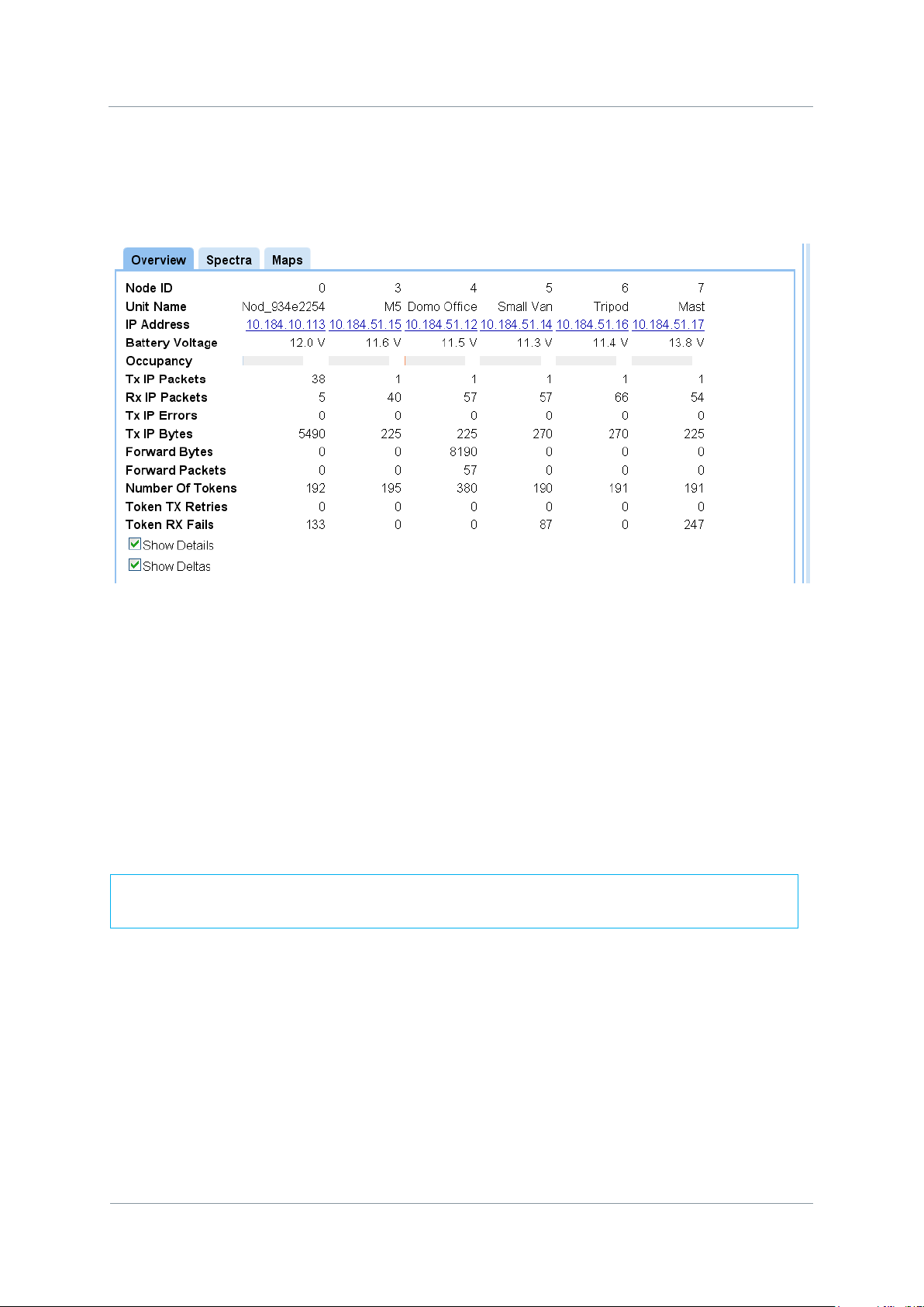
Here is the Status tab with the focus on the Overview pane.
4.1.1. Node ID
We are showing six NETNodes with Node IDs of 1, 2, 4, 5, 6 and 7. There could be up to
twelve NETNodes in a mesh with Node IDs numbered 0 to 11.
4.1.2. Unit Name
The unit name is a „friendly‟ name to make it easier for you to know which NETNode we are
talking about. This name is assigned in the Global Settings Tab.
4.1.3. IP Address
This shows the IP address of the unit that we set up in our initial configuration. Notice that it
is shown as a hyperlink. If you click on one of these hyperlinks the browser will switch to
that NETNode.
4.1.4. Battery Voltage
This returns the current battery voltage of the NETNode. Not so exciting when we are on
mains in the lab but vital when you are looking at a node located on a high building several
miles away which is running on batteries.
Page 44
NETNode
Phase 1 and 2 Units
NETNode
User Manual
NETNode-V2.3
2-35
DS000034 Unclassified
A non zero number indicates a problem with that node (such as antenna position or
interference), and should be corrected as it will drastically reduce system throughput.
4.1.5. Show Details Check Box
If you check this box you‟ll see a whole bunch of data about Tx IP Packets etc. This can give
you vital information about the running of the network.
4.1.5.1. Tx IP Errors
Zero unless the node in question has too much data to send.
4.1.5.2. Number of tokens
This is the number of token passes in a 2 second interval that the node performs. This
higher this number the more data that node can transmit.
4.1.5.3. Number of TX retries
Number of times a token needs to be retransmitted from the node in question. This should
all be zero for a working system.
4.1.5.4. Number of RX fails
Number of times the node does not receive a decode-able transmission. This can be non
zero if a node does not see another node properly in the system. This may be indicated by
red signal strength. Forwarding allows data to be passed between nodes that have a poor
link using other nodes in the system.
4.1.5.5. Show deltas
When ticked all numbers show the parameter over a 2s internal. When not ticked the
numbers are accumulative and updated every 2s.
Page 45

NETNode
Phase 1 and 2 Units
NETNode
User Manual
NETNode-V2.3
2-36
DS000034 Unclassified
Colour
Means…
Green
16 QAM mode – most robust
Amber
QPSK mode – less robust
Red
Basic link only – lowest data rate passing between
nodes
White
Link broken or not configured
4.1.6. Signal Quality
This gives you a simple picture of the signal quality around the mesh system. Ideally, we‟d
like to see steady green boxes for all links. Naturally, mobile units will go out of range or
interference will cause a unit to degrade for a while. One of the clever things about the mesh
is its ability to find a new routing and heal itself thus keeping your network on air.
Here‟s what the colours mean:
Note that a Red link will not guarantee IP data between nodes.
For example the link between node 0(TX) and node 4(RX) is currently Amber.
4.1.7. SNR
This pane shows the Signal to Noise Ratios for each of the NETNodes. For good quality links
this should be in excess of 17dB.
4.1.8. Level A
This pane shows the dBm value for antenna A on the NETNode unit.
4.1.9. Level B
This pane shows the dBm value for antenna B on the NETNode unit.
Page 46

NETNode
Phase 1 and 2 Units
NETNode
User Manual
NETNode-V2.3
2-37
DS000034 Unclassified
It is worth checking that the received signal levels on both antennas are similar. Very
different readings from the inputs can indicate a faulty antenna which should be
replaced.
4.1.10. IP Rx Errs
This pane shows the number of IP receive errors for each NETNode.
Page 47

NETNode
Phase 1 and 2 Units
NETNode
User Manual
NETNode-V2.3
2-38
DS000034 Unclassified
4.2. Status Tab – Spectra Pane
Now let‟s look at the Status tab with the focus on the Spectra pane.
4.2.1. About the Spectra Displays
There are two displays labelled A and B which show the spectra being received on the two
diversity antennas of the NETNode you are attached to.
But, there could be several NETNodes transmitting on the mesh so we need to define
which unit we are looking at.
This is done with the radio buttons on the left side of the spectra display. In our example,
the radio button for Domo Office is selected. This means the two displays are showing
spectra for the Domo Office NETNode transmissions as received on our node‟s two
antennas.
4.2.2. Interference
The last radio button is called interference. When you select this, the displays show the
spectra when none of the NETNodes in the mesh are transmitting. This enables us to look
for interference on the frequency we are planning to use for our mesh.
Page 48

NETNode
Phase 1 and 2 Units
NETNode
User Manual
NETNode-V2.3
2-39
DS000034 Unclassified
The NETNode we have selected has a GPS unit
connected and the Use GPS check box is checked.
This means that the NETNode can broadcast
precise information about its location to other
nodes or fixed assets on the mesh (assuming that
the GPS is locked to the GPS satellite
transmissions).
4.3. Status Tab – Maps Pane
4.3.1. Radio Buttons
The radio buttons enable you to choose between Network and one of four map displays
for the mesh. Leave it on Network for now.
4.3.2. Node Information
Under the radio buttons you‟ll see some node information about the NETNode you are
currently attached to. We talked about this information in the Overview Pane above.
4.3.3. GPS Information
Page 49

NETNode
Phase 1 and 2 Units
NETNode
User Manual
NETNode-V2.3
2-40
DS000034 Unclassified
Colour
Means…
Green
16 QAM mode – most robust
Amber
QPSK mode – less robust
Red
Basic link only – lowest amount of data passing
White
Link broken or not configured
4.3.4. Show Details Check Box
When the Show Details check box is checked the node information shown above is
expanded to show the information listed in the 4.1.5 Show Details Check Box section of this
manual. Only the details for the selected Node are displayed.
4.3.5. Network Display
In the example above you can see the network display is selected. This gives a simple
graphical view of the NETNodes in the mesh and the links between them.
Note: The buttons above the display are greyed out as they have no function when the
Network radio button is selected.
Each NETNode is shown as a circle with a white number. (If the number turns red, then the
node is temporarily congested).
If you have the Show Names check box checked, you‟ll also see the node name displayed.
The links between the nodes are shown as coloured lines. As each NETNode supports
bidirectional operation there are normally two lines for each link.
In the example above you are seeing static lines but when you are connected to a live
system, you‟ll see these lines changing state and the RF environment changes or NETNodes
move about.
Page 50
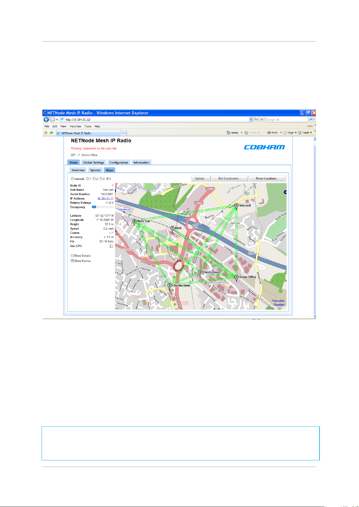
NETNode
Phase 1 and 2 Units
NETNode
User Manual
NETNode-V2.3
2-41
DS000034 Unclassified
4.3.6. Map Display
Now select one of the numbered radio buttons. This changes the display to the map
display. There are four possible map displays each selected by a radio button. Refer to
section 4.3.9 Upload Map Data to learn how to put maps into the units prior to use.
You‟ll see the mesh network diagram overlaid onto a map of the area showing the nodes and
the links between them.
There are two ways you can place the nodes onto the map:
Manual Placement
GPS Placement
4.3.7. Manual Placement
Position the mouse pointer over the node symbol. The pointer will change to a four-headed
arrow. Left click and drag the node to the position on the map where the node should be
displayed.
Note: You can drag a node symbol to anywhere on the map. Normally, you would place
the symbol where the node is actually located, but there is nothing to stop you just randomly
placing the symbol in Portsmouth when the physical NETNode is in Southampton for
example.
Page 51

NETNode
Phase 1 and 2 Units
NETNode
User Manual
NETNode-V2.3
2-42
DS000034 Unclassified
4.3.8. GPS Placement
If a NETNode has a GPS unit connected it can report its position which can then be displayed
on the map. Section 6.3 Configuring NETNode for GPS details how to connect GPS to a
Mesh.
1. Ensure you are connected to a NETNode with GPS attached.
2. Ensure the Use GPS check box is checked.
3. The symbol for that node will now snap to the correct location on the map where the
actual NETNode is currently located. If it moves, it will move on the map, showing
heading speed and height.
4.3.9. Upload Map Data
Each of the four map radio buttons can contain a different map. These maps need to be
uploaded before you can use them.
4.3.9.1. Upload Map Image File
To upload a map you‟ll need an internal drive which has been formatted. (Information Tab).
You‟ll also need an image file containing the map for the area you are interested in. The
system supports four file types for maps:
.JPG
.PNG
.GIF
.BMP
We recommend using JPEG or PNG as they are good quality but small files. Bitmaps on the
other hand are excellent quality but very large. There is a limited amount of memory
available in each NETNode for maps.
1. Click the Upload… button
2. The Upload Map Data dialog opens
3. Click the Browse button and navigate to your image file.
4. Click the Upload File button to place the image in the NETNode‟s flash memory.
Page 52

NETNode
Phase 1 and 2 Units
NETNode
User Manual
NETNode-V2.3
2-43
DS000034 Unclassified
4.3.9.2. Set Coordinates
When you have loaded your map, you‟ll need to find out the coordinates of three of the
corners of the map image to enable the GPS feature to work.
You‟ll need to know the Top Left, Top Right and Bottom Left coordinates of your image.
These coordinates must be in decimal form and accurate to six places. (You may be more
familiar with Latitude and Longitude being expressed in hours minutes and seconds).
You can get the coordinates from your map data source for example.
1. Click the Set Coordinates button.
2. The Coordinates dialog box opens.
3. Type in the coordinates of each of the corners of the image.
4. Click OK.
4.3.9.3. Reset Locations…
When you have loaded a new map or you have been moving nodes on an existing map you
may need to reset their locations. This can be useful if you lose nodes off the edge of the
map.
You can force the system to reset the locations of all the nodes or any combination of
them.
1. Click the Reset Locations… button
2. The Reset Locations dialog opens
Page 53

NETNode
Phase 1 and 2 Units
NETNode
User Manual
NETNode-V2.3
2-44
DS000034 Unclassified
3. Click the All button or check the nodes you want to reset
4. Click OK
5. The system resets the locations and switches off the GPS tracking function.
Page 54
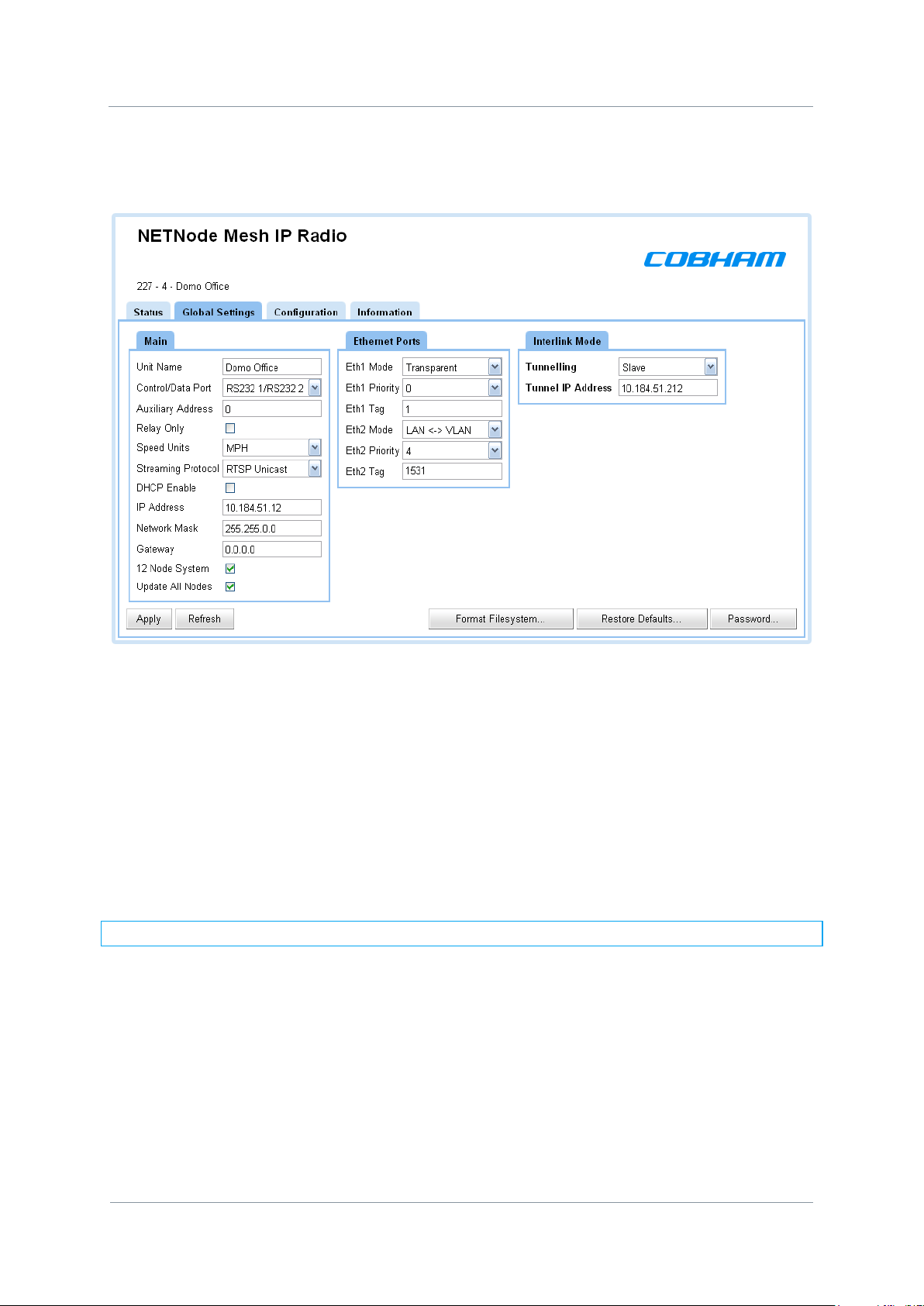
NETNode
Phase 1 and 2 Units
NETNode
User Manual
NETNode-V2.3
2-45
DS000034 Unclassified
4.4. Global Settings Tab
4.4.1. Unit Name
The NETNodes are uniquely identified by the Node ID parameter which is a number
between 0 and 11.
This is not a very useful name for normal operations so this text box allows you to enter a
better description for the node which will appear on network diagrams and maps within the
software.
1. Type in a meaningful name for the NETNode.
2. This name will be used in all maps and network diagrams for this node
Note: You can use up to 12 alphanumeric characters for the Unit name
4.4.2. Control/Data Port
On a Phase 1 NETNode unit the Control/Data port uses the CA0288-5 cable which has an
Amphenol 19-way plug (m) on one end and two D-Type 9-way plugs (f) on the other end
labelled RS232 and RS485. On a Phase 2 Plain box NETNode the Control/Data port is labelled
AUX and uses the CA0474 cable which has two D-Type 9-way plugs (f) on the other end
labelled RS232 and RS485. On a Phase 2 Robust unit the Control/Data port uses CA0406
which has an Amphenol plug (m) on one end and two D-Type 9-way plugs (f) on the other
end labelled RS232 and RS485.
Normally we use RS232 for Control.
Page 55

NETNode
Phase 1 and 2 Units
NETNode
User Manual
NETNode-V2.3
2-46
DS000034 Unclassified
Setting
Means…
RS232/RS485
Control is RS232 plug, Data Port is RS485 plug
(normal)
RS485/RS232
Control is RS485 plug, Data Port is RS232 plug
RS232/RS232
Special mode, only used for engineering.
Setting
Means…
RS232 1/RS232 2
Data is on RS232 plug
RS232 2/RS232 1
Control is on RS232 plug
There may be times when you want to change this and so this combo box enables you select
other setting for the plugs on this cable.
You can select from the Control/Data Port box:
On both Phase1 and Phase2 Mesh nodes up to and including Software release V1.4 there is
only one data channel and one serial control channel. If the Data channel is set to the RS232
port then the control channel is forced to the RS485 port and vice versa.
4.4.2.1. Control/Data Port - Software Version 2.1
Software version 2.1 allows for the use of two separate data channels RS232 and RS485.
The RS485 is now a dedicated port on the unit. The RS485 can no longer be configured to
be a Unit Control channel – it is now a dedicated data channel.
The RS232 data channel shares with the control port. So the RS232 serial port can be set to
be a second data channel.
A second RS232 port is available on units without the AVI option fitted and this second
channel can also be configured to be a data channel or a control port. If the AVI option is
fitted then the second serial port is used to control the AVI encoder.
Caution: D830 – Do not set the control data port to „Data is on RS232 plug‟ if you are
controlling the unit via this port, and the unit cannot be controlled via IP.
4.4.3. Auxiliary Address
Normally, the NETNode will be operating with IP devices like cameras microphones or GPS
units and the Auxiliary address is left as 0.
Page 56

NETNode
Phase 1 and 2 Units
NETNode
User Manual
NETNode-V2.3
2-47
DS000034 Unclassified
Some NETNodes (the AVI variant) are able to use composite cameras. To do this they have
an extra Video / Audio and data encoder board fitted inside the unit.
To ensure the NETNode recognises and uses the internal encoder card we have to set the
auxiliary address to 1. Now your composite camera can be used with the system.
Caution: If you ever reset defaults on the NETNode it will reset the Auxiliary Address to
zero. You must reset this to 1 for your composite camera to work.
4.4.4. Relay Only
Normally each NETNode will have at least one source of sensor data attached to it, for
example, a camera or a microphone.
However, occasionally the NETNode only needs to act as a relay, for example, when you are
setting up a chain network for range extension or working with a helicopter relay.
In this case you would check the Relay Only check box.
Note: When the Relay Only check box is checked it simply disables any Ethernet
connectivity to the NETNode.
4.4.5. Speed Units
If you have a GPS connected to a NETNode it can supply speed data. You can choose the
units you want to use for speed in this combo box. The possible choices are:
Knots
MPH
KPH
4.4.6. Streaming Protocol
This allows either multicast (raw UDP) or RTSP streaming (RTP multicast/unicast) of the
internal video encoder. See Section 5 on Streaming as this explains the intricacies of Video
streaming over IP in more detail.
4.4.7. DHCP Enable
In some situations having DCHP enabled may be appropriate for advanced users of the
system but in most cases it‟s better if each NETNode has its own fixed address. Fixed IP
address allocation is better when a system is in a dynamically changing environment as
operation is such an environment means that connection to the DHCP server can not always
be guaranteed.
If checked, then the NETNode will try to acquire its IP address from a DHCP server on the
network – this DHCP server can be located through another NETNode over the radio
interface.
4.4.8. IP Address
If the NETNode is not automatically acquiring its IP address via a DHCP server then a fixed
IP address needs to be assigned to the unit. This address is typically obtained from a
Page 57

NETNode
Phase 1 and 2 Units
NETNode
User Manual
NETNode-V2.3
2-48
DS000034 Unclassified
Note: All nodes on the Mesh must have the same mode set. To change all the nodes
from an 8 Node (compatible) to the new 12 Node system use the update all nodes
tickbox.
network administrator to avoid a clash of IP addresses on any network. The unit is expecting
an IPv4 address.
Enter an IP address for this NETNode in the IP address text box. It can be any class of
network you choose.
4.4.9. Network Mask
The network mask allows a network administrator to break a network into smaller more
efficient subnets to prevent excessive numbers of IP packets being routed through the
network. This is normally defined by the network administrator
Enter a subnet mask in the Network mask text box.
4.4.10. Gateway
A default gateway is used by a host when an IP packet's destination address belongs to
someplace outside the local subnet. The default gateway address is usually an interface
belonging to the LAN‟s border router.
We recommend you leave the gateway at 0.0.0.0
4.4.11. 12 Node System
This box should be ticked for support for up to 12 nodes. It should be unticked if backwards
compatibily with V2.x (8 Node) software.
4.4.12. Update All Nodes
When you make changes to any setting they are normally applied only to the NETNode you
are currently attached to. Sometimes it‟s really convenient to update all the NETNodes in the
mesh, for example when you want to change the frequency of all units at the same time.
Check the Update All Nodes checkbox to enable these global updates on all nodes. Not all
parameters are updated globally on the Mesh:- just Frequency, Bandwidth, Encryption, RTSP
streaming, 12 Node system mode parameters.
CAUTION: All nodes in a Mesh must be in range and connected for a „Update all Nodes‟
command to work across the whole Mesh. If the command is issued and while a node has
dropped out of the Mesh as it is out of range then it will not receive the command and may
not reconnect to the Mesh when it returns into coverage. If this happens changing the
parameters back to the original values may restore operation.
Page 58

NETNode
Phase 1 and 2 Units
NETNode
User Manual
NETNode-V2.3
2-49
DS000034 Unclassified
Flash
Use
Internal Flash
Holds the maps and coordinate files.
External Memory Card
Use for video recording on Phase 2 units
4.4.13. Setting the clock (Phase 2 units only)
The real time clock is used to timestamp the recordings on the external memory card. The
clock may either be set manually or synchronised to a GPS unit connected to any node of the
system. The clock internally runs in UTC time and the user may set the time-zone offset and
daylight saving time. Note the units do not automatically adjust for daylight savings.
4.4.14. Format File System…
There are two flash drives built into each NETNode.
Internal Flash
External Memory Card
Note: The External memory card is only available on Phase 2 units
Note: The External memory card slot ONLY support basic 2GB or 4GB SD cards
Page 59

NETNode
Phase 1 and 2 Units
NETNode
User Manual
NETNode-V2.3
2-50
DS000034 Unclassified
Here‟s how you format these drives:
1. Click the Format File System… button
The Format Flash File system dialog opens
2. Click Format Internal Flash button
3. Your internal Flash drive will be formatted.
Caution: When you press the Format Internal Flash button the system does not ask you
to confirm your actions – it just formats the drive. Be very sure you want to do this.
Note: If you want to format the External Memory Card, click the Format External
Memory Card button at step 2 above.
4.4.15. Restore Defaults…
To restore a default condition to the whole unit:
1. Click the Restore Defaults button
2. The Restore Defaults dialog opens
3. Click the OK button
Page 60

NETNode
Phase 1 and 2 Units
NETNode
User Manual
NETNode-V2.3
2-51
DS000034 Unclassified
4.4.16. Change Password…
1. Click the Password… button
2. The Change Password dialog opens
3. Type in the Old Password
4. Type in the New Password in the New Password text box
5. Type in the New Password in the Confirm New Password text box
6. Click the OK button
Page 61

NETNode
Phase 1 and 2 Units
NETNode
User Manual
NETNode-V2.3
2-52
DS000034 Unclassified
4.5. Configuration Tab – Transmitter Pane
Note that there are eight configuration tabs enabling you to have eight completely different
setups stored in the NETNode. We are going to look at just tab one – they are all identical.
In the example above, the green square on tab 1 shows we are working on configuration
number one.
The transmitter pane enables you to change the frequency of a NETNode, set the
transmission bandwidth and adjust the output power level of the NETNode.
4.5.1. Preview and Active Configuration
A configuration can be Active or Previewed. This can be determined by looking at the
Configuration numbers. The active configuration is darker blue than the inactive
configurations. To preview a configuration the user can click the configuration number and
the previewed configuration is then highlighted in Green. A user is able to preview
configurations without activating the configuration. To activate a previewed configuration the
user needs to click the „Apply‟ button.
Page 62

NETNode
Phase 1 and 2 Units
NETNode
User Manual
NETNode-V2.3
2-53
DS000034 Unclassified
Note: All configuration parameter changes need to be confirmed by clicking the „Apply‟
button before the changes are activated
4.5.2. Enable Transmitter Check Box
This simply turns on the transmitter when checked. All NETNodes in a mesh must have their
transmitters enabled.
4.5.3. Frequency
Input the frequency in MHz that you want to use for this NETNode.
4.5.4. Channel Bandwidth
You can configure the channel bandwidth with this combo box. There are three choices:
2.5 MHz
3.0 MHz
3.5 MHz
5.0 MHz (V2.1 software and unit types 68 upwards only)
See Section 4.12 Information Tab to discover the Board type and the Software version.
4.5.5. Output Level High and Output Level Low
These two text boxes allow you to set the level of attenuation in dB that will be applied to
the low and high output levels. This could be useful if your transmitter is swamping another
unit in close proximity. You can set anything between 0 to 30 dB.
4.5.6. Output Level Select
You can choose high or low output level to suit the RF environment you are working in.
When you select high or low here it applies any attenuation you have set in the output level
setting discussed above.
Page 63

NETNode
Phase 1 and 2 Units
NETNode
User Manual
NETNode-V2.3
2-54
DS000034 Unclassified
4.6. Configuration Tab – Mesh Pane
4.6.1. Mesh ID
The Mesh ID tells the unit which group it belongs to. All NETNodes on Mesh ID 122 for
example will communicate with each other.
This means you could set up another mesh with Mesh ID 125 for example on the same
frequency which would run independently of Mesh 122 (though you
careful about interference and run the units in separate areas).
You can choose any numbers from 001 to 255 for your Mesh ID. Different Mesh systems
should not be allowed to co-exist on the same frequency.
4.6.2. Node ID
The Node ID gives the unit a unique ID within the mesh. You can have up to twelve
NETNodes in a mesh and they each must carry a unique Node ID.
You can choose any numbers from 0 to 11 for your Node ID.
would
have to be
A node may choose to automatically reassign its‟ node ID on power if it conflicts with an
existing node on the network.
4.6.3. IP Forward
If this NETNode is connected to an IP source then checking the IP Forward check box will
ensure this data is passed around the mesh for access on other units. A node will forward IP
data when it finds that the data cannot get from the source node to the destination node in
a single hop. Leave this box checked for normal operation.
4.7. Configuration Tab – Streamer Pane
When you have got the asset to the NETNode, you may want to stream that information
down a fixed IP link. The streamer pane enables you to configure this facility easily for
Multicast IP streaming.
Streaming is the transmission of digital audio or video or the listening and viewing of such
data without first storing it.
In Cobham systems we have the ability to carry streams using Multicast, Unicast and RTSP
protocols. The protocol selection is performed within the Global settings tab (see Section
4.4.6 Streaming Protocol).The Streamer pane within the configuration tab is purely
associated with Multicast streams. These streams can come from external or internal
sources. This is controlled by the Source Mask.
To ensure we don‟t overload the bandwidth we want to be able to choose which nodes get
to receive the stream. This is controlled by the Destination Mask.
Page 64

NETNode
Phase 1 and 2 Units
NETNode
User Manual
NETNode-V2.3
2-55
DS000034 Unclassified
Source
Front Panel
Label
Connector
(Robust Units)
Connector
(Plain Box)
Eth0
IP
Amphenol
RJ45 (f)
Eth1
CTRL/DATA
Amphenol
RJ45 (f)
Encoder
Internal (if fitted)
Internal (if fitted)
Internal (if fitted)
4.7.1. Source Mask
The Source Mask enables the streaming of Video that originates from a network connected
to either one of the two NETNode Ethernet ports or from the internal encoder (if it is fitted).
Here‟s how to configure it:
1. Click the Source Mask Set… button
2. The Streamer Source Mask dialog will open
3. Place a check mark in the check box that is the source to stream down the link.
4. Click OK
In our example we are planning to stream from the composite camera connected to the
internal AVI encoder.
Here are all the possible connections involved:
Eth0 and Eth1 will be from a network connected to the NETNode. Encoder will ONLY be
valid if the NETNode has the AVI-UP option (internal AV Encoder) fitted.
Page 65

NETNode
Phase 1 and 2 Units
NETNode
User Manual
NETNode-V2.3
2-56
DS000034 Unclassified
4.7.2. Destination Mask
You can choose which NETNodes will receive the stream. Your NETNode could have up to
eight NETNodes attached to it via the mesh. Multicast streaming to all nodes is an inefficient
use of mesh capacity and so you need to be able to restrict the multicast to specific nodes.
1. Click the Destination Mask Set… button
2. The Streamer Destination Mask dialog will open
3. Check the node check boxes for the NETNodes that you want to receive the stream.
4. Click OK
When RTSP streaming is enabled this box will be greyed out and the destination mask
selected automatically as defined by the RTSP connection.
Note: The Eth0 and Eth1 are ticked by default. These ports will be used as the exit point
from the mesh at the node(s) you have specified.
4.7.3. Multicast Address
This text box enables you to change the multicast address used by the unit. The default
value is 239.16.33.254.
Page 66

NETNode
Phase 1 and 2 Units
NETNode
User Manual
NETNode-V2.3
2-57
DS000034 Unclassified
4.7.4. SAP Address
This text box enables you to change the value of SAP/ SDP multicast address used by the
unit.
The default value is 224.2.127.254 and the port used is 9875.
These are standard multicast values for such parameters, and it is recommended they are
not changed unless specifically required due to routing restrictions.
4.7.5. Port
Protocols like TCP or UDP use port numbers in the header to direct traffic around the
network. Low port numbers are used by computer systems for predefined tasks. For example
SMPT (for your email service) uses port 25.
A good rule is to use numbers above 10,000 to avoid conflict with existing services.
When you set up a port number on several computers on a network they will all listen for
packets directed to that port.
The default value is random.
4.7.6. Service Name
This text box lets you name the multicast stream as delivered in the SAP/SDP packets from
the unit. Default is MPEG Stream.
4.8. Configuration Tabs – Data RS232/RS485 Pane
The NETNode can send and receive data through either of its RS232 serial port, and its
RS485 serial port (V2.1 onwards). Configuration of the RS232 port is found under the
Global Settings tab (see Section 4.4.2 Control/Data Port).
It is possible to configure the system to send data from one NETNode serial port to another
NETNode serial port or from a NETNode to a PC connected on the same IP network.
4.8.1. Data Mode
The Data Port can be configured in three ways:
Off
UDP
TCP server
TCP client (V2.1 onwards)
4.8.1.1. Off
Data transfer is switched off.
Page 67

NETNode
Phase 1 and 2 Units
NETNode
User Manual
NETNode-V2.3
2-58
DS000034 Unclassified
To send data between two nodes the data IP address of each node should point at the
other and the ports must match.
To send data between two nodes one node should be set to server, one to client, the IP
address of each node should point at the other and the ports must match.
4.8.1.2. UDP
UDP (User Datagram Protocol) is used to move data about the network. The packets are
sent out and the system does not expect a reply. There is no way that the sending device
can tell if the data arrived at the destination.
4.8.1.3. TCP Server
TCP (Transmission Control Protocol) is used to move data about the network. The packets
are sent out and the system will expect a reply. Each message is acknowledged by the
destination device.
4.8.1.4. TCP Client
This mode allows the NETNode data port to connect to another NETNode in server mode
using a robust TCP link.
4.8.2. Baud Rate
This is where you set the speed at which data will be transferred across the network. Speeds
available are: None, 1200, 2400, 4800, 9600, 19200, 38400, 57600, and 115200.
Note: The data is assumed to be 8 bits.
4.8.3. Parity
A parity bit is a bit that is added to ensure that the number of bits with the value one in a
set of bits is even or odd. Parity bits are used as the simplest form of error detecting code.
There are two variants of parity bits: even parity bit and odd parity bit.
This combo box allows you to set: None, Even and Odd.
4.8.4. IP Port and IP Address
These set an IP address and Port to and from which the data will transferred.
The user can connect to the data port via telnet by setting the mode to TCP server and the
port number to 23.
The user can connect two data ports on different units together via setting UDP mode and
using the matching port numbers.
Page 68

NETNode
Phase 1 and 2 Units
NETNode
User Manual
NETNode-V2.3
2-59
DS000034 Unclassified
4.8.5. GPS Source
It is possible to connect a GPS receiver to a NETNode. This switch enables you to select the
source for the GPS. There are three choices: None, RS232 Port, RS485 port and
Encoder. None simply turns off the GPS facility.
4.8.5.1. Encoder (V2.1 upwards)
From V2.1 software onwards it is possible to connect the GPS to the Encoder data input port
(if AVI is fitted). This is only possible with the AVI variant of the NETNode. The encoder
encryption must be disabled for this to work.
Page 69

NETNode
Phase 1 and 2 Units
NETNode
User Manual
NETNode-V2.3
2-60
DS000034 Unclassified
4.8.6. IP Data Scrambling
It can be important to scramble sensitive data before they are passed across radio networks.
The system offers AES128 and AES 256 and this encrypts all user data exchanged over the
network.
The AES128+ and AES256+ settings ensure that the NETNode will only receive encrypted
data. Any data sent in the clear by any nodes will not be accepted by a NETNode if the AES+
is set on the unit.
This combo box enables you to select the scrambling scheme you want to use. You can
select: AES128, AES128+, AES256 and AES256+.
4.8.7. Scrambling Key
When you choose to use a scrambling scheme you need to specify a key that it will use.
Here‟s how:
1. Click the Scrambling Key Set… button
2. The Scrambling Key dialog open
3. Select the Key type from the Key Type combo box
4. Type your key in the „xxx‟ bit key combo box
5. Click OK
Note: If you make a mistake when typing the key, use the Clear button.
Page 70

NETNode
Phase 1 and 2 Units
NETNode
User Manual
NETNode-V2.3
2-61
DS000034 Unclassified
4.9. Configuration Tab – Record Pane
The NetNode unit (Phase 2 only) allows recording of the video from the AVI unit unto a SD
card.
Files are recorded in 30 second lengths, referred to as a „chunk‟, and stored in a compressed
transport stream format. They can be subsequently downloaded either through the WEB
browser from the file system tab, or alternatively the card may be inserted into an external
computer. Files are stored in FAT16 format and so can easily be read. The date and time is
always stored in UTC format regardless of the time-zone setting.
The card should only be removed when the SD card LED is green and not red. This always
occurs at the end of the 30s transfer when record is enabled. Failure to do this may result in
a damaged file system on the card.
The unit currently supports micro SD cards only.
4.9.1. File length
This is the maximum number of files stored on the card the oldest will be removed first. This
should be set so that the number of files does not exceed the capacity of the SD card.
4.9.2. Record
Tick box to start recording. Untick the box to stop.
4.10. Configuration Tab – Audio Pane
NETNode phase 2 contains an audio talkback feature which allows operatives to
communicate over the mesh using their own headset. The system allows each user to talk to
all other users. To use this feature, a headset with microphone needs to be connected to the
unit. The NETNode unit provides a small amount of power to the microphone capsule.
The pin-outs for the talkback audio connectors can be referenced in Section 12.6 T/B - 6-pin
0B LEMO socket (G-key) for the Plain box unit and Section 13.3 Misc Connector Amphenol
38999 Series 3 13-35 22 way chassis socket for the Robust variant.
Note: Phase 1 units do not support Audio Talkback
Page 71

NETNode
Phase 1 and 2 Units
NETNode
User Manual
NETNode-V2.3
2-62
DS000034 Unclassified
4.10.1. Mode
To enable this feature the „Mode‟ drop down box must be set to „local‟ or „remote‟.
Local mode only distributes the talk back audio within the local Mesh. Remote mode allows
the onward distribution of this audio on an external IP network using RTSP protocols.
The remote mode also allows external „eavesdropping‟ of the audio using the url:
rtsp://ip_address_of_unit/audio.sdp
Audio may also be sent to that unit using the same port as the RTP packet. The audio format
must be G726-32 with a payload size of 512 bytes.
4.10.2. Microphone Gain
This sets the microphone gain.
4.10.3. Headphone Gain
This sets the headphone volume.
4.10.4. Mute Level
Set the level at which is microphone is enabled. Below this level no packets are sent. An
external push to talk switch can be connected with the microphone to serve the same
purpose if required.
All NetNode units provide a low level bleep tone when no talkback is received and the unit is
connected onto the mesh network.
4.11. Configuation Tab – VLAN Pane 1-8
Upto 8 VLANs may be programmed for each NetNode.
4.11.1. Tag
VLAN Tag number.
4.11.2. IP address
IP address of unit for this VLAN.
4.11.3. Sub Mask
Subnet mask for this VLAN.
Page 72

NETNode
Phase 1 and 2 Units
NETNode
User Manual
NETNode-V2.3
2-63
DS000034 Unclassified
4.12. Information Tab
The information tab gives you some details about the hardware and software loaded into
your NETNode unit. This could be very valuable during a support call to help our engineers
to assist you.
We discussed how to load maps and coordinates in an earlier section of this guide. By
clicking on the File System… hyperlink on this page you can get access to the files. Here
you‟ll find all your maps and configuration files which you may want to share with other
units.
Page 73

NETNode
Phase 1 and 2 Units
NETNode
User Manual
NETNode-V2.3
2-64
DS000034 Unclassified
4.13. Encoder Tab
If you have a NETNode which has the AVI option installed you will be able to use a
composite camera (PAL or NTSC) connected to the AV jack on the front panel of the unit.
When you are using a NETNode with a video encoder, you‟ll see an extra tab on the control
software called Encoder. This is where you configure the encoder features.
4.13.1. Encoder Preset
You can choose from a number of encoder options.
4.13.2. Video Lock
This block will show Red when there is no video lock. It shows Green when video is locked.
4.13.3. Audio Enable
Check the Audio Enable check box to turn on the audio. Audio will now take some of the
available bandwidth. For some applications you may wish to turn off audio to allow all the
bandwidth to be used by video.
4.13.4. Scrambling
It can be very important to scramble received composite assets before they are passed
across networks.
The system offers AES128 and AES 256 and this encrypts all composite assets exchanged
over the network.
This combo box enables you to select the scrambling scheme you want to use. You can
select: AES128 or AES256.
Page 74

NETNode
Phase 1 and 2 Units
NETNode
User Manual
NETNode-V2.3
2-65
DS000034 Unclassified
Note: This scrambling of the composite signal is independent of the main IP
Scrambling on the node. This composite scrambling is nested under the main IP
scrambling. This means you can scramble the Composite signal and then scramble the whole
IP data again.
4.13.5. Scrambling Key
When you choose to use a scrambling scheme you need to specify a key that it will use.
Here‟s how:
1. Click the Scrambling Key Set… button
2. The Scrambling Key dialog open
3. Select the Key type from the Key Type combo box
4. Type your key in the xxx bit key combo box
5. Click OK
Note: If you make a mistake when typing the key, use the Clear button.
If you check the Show Advanced Options check box, the dialog will expand like this:
Page 75

NETNode
Phase 1 and 2 Units
NETNode
User Manual
NETNode-V2.3
5-66
DS000034 Unclassified
5. Streaming over IP
5.1. General Info
This section is relevant only to customers that have the NETNode-AVI-UP option fitted into
their NETNode unit.
5.2. Multicast Streaming
The NetNode supports both raw multicast streaming and RTSP/RTP streaming.
5.2.1. Streamer Operation
For multicast streaming the transport stream video data is transmitted over the Ethernet
network by means of “multicasting” i.e. continuous real-time streaming of packets accessible
to any PC connected to the network.
It is therefore possible for more than once connected PC to view the streamed data
simultaneously.
Two types of multicast IP packets are streamed.
Packets carrying video, audio and data as received by the unit;
Packets known as Session Announcement Protocol and Sessions Description Protocol
data (SAP and SDP), which contain information regarding the nature and location of the
stream itself.
5.2.2. Configuration Tab – Streamer Pane (Multicast Mode)
When you have got a Video or Audio product into the NETNode, you may want to stream
that information down a fixed IP link. The streamer pane enables you to configure this
facility easily.
Streaming is the transmission of digital audio or video or the listening and viewing of such
data without first storing it.
In Cobham systems we have the ability to carry streams using multicast protocols and these
streams can come from external or internal sources. This is controlled by the Source Mask.
To ensure we don‟t overload the bandwidth we want to be able to choose which nodes get
to receive the stream. This is controlled by the Destination Mask.
5.2.2.1. Service Name
Textual information naming the multicast stream as delivered in the SAP/SDP packets from
the unit. Default is “Mesh Streaming”
5.2.2.2. Source Mask
The Source Mask enables the streaming of Video that originates from a network connected
to either one of the two NETNode Ethernet ports or from the internal encoder (if it is fitted).
Page 76

NETNode
Phase 1 and 2 Units
NETNode
User Manual
NETNode-V2.3
5-67
DS000034 Unclassified
Source
Front Panel
Label
Connector
(Robust
Units)
Connector
(Plain Box)
Eth0
IP
Amphenol
RJ45 (f)
Eth1
CTRL/DATA
Amphenol
RJ45 (f)
Encoder
Internal (if
fitted)
Internal (if
fitted)
Internal (if
fitted)
This pop-up box enables the streaming of Video from either one of the two external Ethernet
ports or from the internal encoder (if it is fitted). Enabling one of the two Ethernet ports
allows a stream on an external network connected to the NETNode Ethernet ports to pass
into the Mesh network. Enabling the Encoder tick box allows the internal MPEG encoder (if
fitted in the NETNode as option NETNode-AVI-UP) to stream over the Mesh network.
Here‟s how to configure it:
1. Click the Source Mask Set… button
2. The Streamer Source Mask dialog will open
3. Place a check mark in the check box that is the source to stream down the link.
4. Click OK
In our example we are planning to stream from the composite camera connected to the
encoder.
Here are all the possible connections involved:
Eth0 and Eth1 will be from a network connected to the NETNode. Encoder is ONLY valid
IF the NETNode has the AVI-UP Option (internal AV Encoder) fitted.
5.2.2.3. Destination Mask
You can choose which NETNodes will receive the stream. Your NETNode could have up to
eight NETNodes attached to it via the mesh. Streaming to all nodes is an inefficient use of
mesh capacity and so you need to be able to restrict the multicast to specific nodes.
This pop up box allows the user to specify precisely which nodes need to receive the stream.
Streaming to all nodes may be an inefficient use of MESH IP capacity and so the user may
wish to restrict the multicast to specific nodes.
Note: Please note after hitting the OK box on the source or destination mask, the main
Apply Bottom must be pressed to action the command.
Page 77
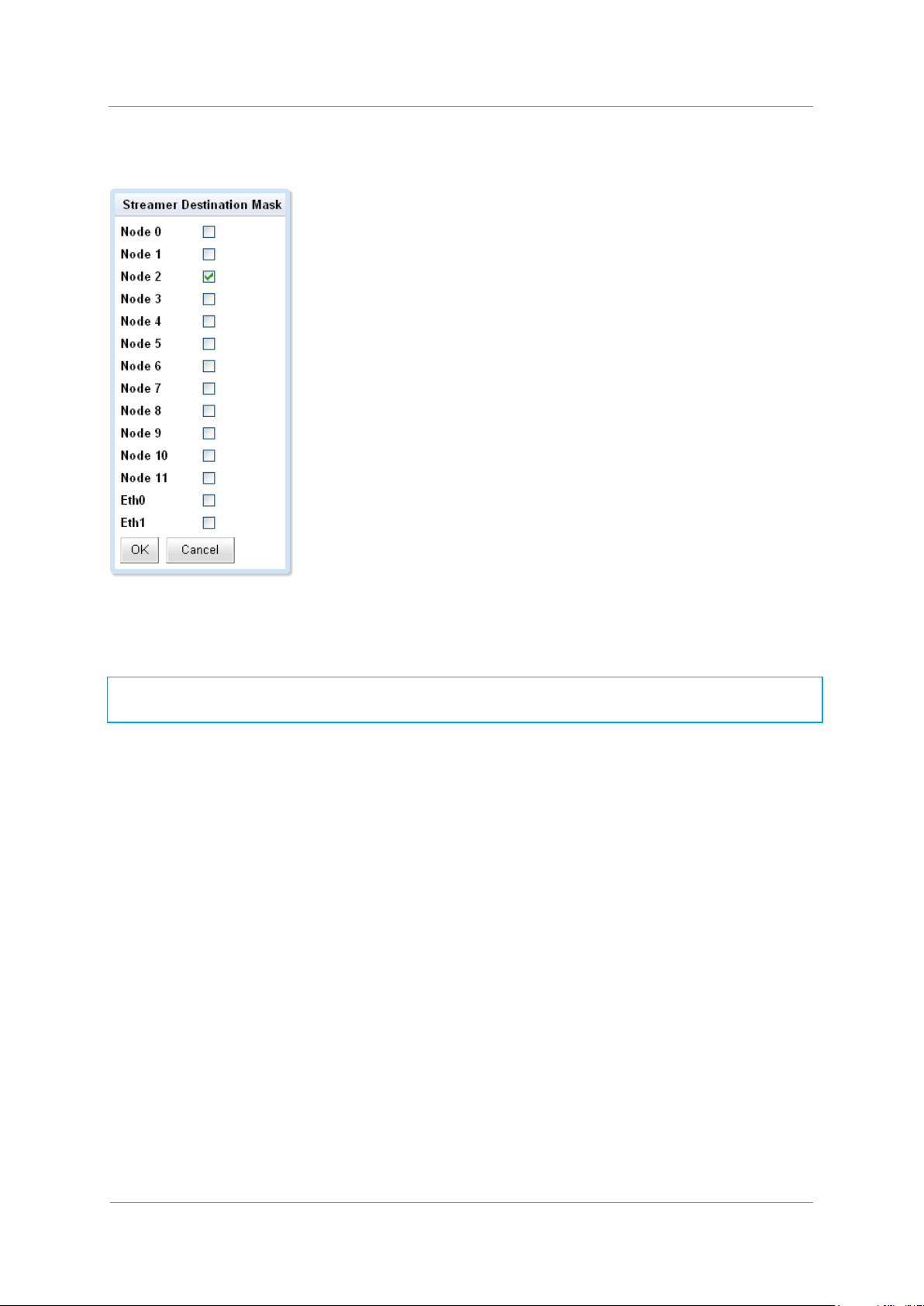
NETNode
Phase 1 and 2 Units
NETNode
User Manual
NETNode-V2.3
5-68
DS000034 Unclassified
1. Click the Destination Mask Set… button
2. The Streamer Destination Mask dialog will open
3. Check the node check boxes for the NETNodes that you want to receive the stream.
4. Click OK
Note: The Eth0 and Eth1 are ticked by default. These ports will be used as the exit point
from the mesh at the node(s) you have specified.
5.2.2.4. Multicast Address
This text box enables you to change the multicast address used by the unit. The default
value is 239.16.33.254.
5.2.2.5. SAP Address
This text box enables you to change the value of SAP/ SDP multicast address used by the
unit.
The default value is 224.2.127.254 and the port used is 9875.
These are standard multicast values for such parameters, and it is recommended they are
not changed unless specifically required due to routing restrictions.
5.2.2.6. Port
A good rule is to use numbers above 10,000 to avoid conflict with existing services.
When you set up a port number on several computers on a network they will all listen for
packets directed to that port.
Page 78

NETNode
Phase 1 and 2 Units
NETNode
User Manual
NETNode-V2.3
5-69
DS000034 Unclassified
SD card slot behind
cap
5.2.2.7. Service Name
This text box lets you name the multicast stream as delivered in the SAP/SDP packets from
the unit. Default is MPEG Stream.
5.3. RTSP Streaming
Real Time Streaming Protocol allows automatic control of the routing through the Mesh
system. To use this feature the streaming protocol box should be set to the same RSTP
multicast or unicast modes for all nodes in the system (this will happen if the „update all
nodes‟ checkbox is ticked). The streaming protocol is selected on the Global Settings tab –
see Section 4.4.6 Streaming Protocol for details.
To access a stream on an AVI unit the URL is as follows:
rtsp://<ip_address_of_AVI_unit>/stream.sdp
This will automatically set the internal destination masks of the AVI node and the endpoint
node (the node where the data emerges from the Ethernet) to the correct values. The
destination values displayed in the destination mask on the Configuration Tab no longer have
any effect in this mode of operation.
If necessary the endpoint node will convert the multicast RTP packets to unicast (and remap
the port numbers) if the Software player does not support multicast streaming. Unicast may
also be forced by setting the mode to RTSP unicast. The Mesh always uses multicast packets
internally as this is more bandwidth efficient when reaching multiple destinations.
Note the player must be able to support transport stream packets (MP2T – suitable players
include VLC media player). Ports on different AVI NETNodes should be set to different
unique values (use even addresses for RTSP/RTP).
The source mask, internal multicast address, service name and port number are still used in
this mode.
5.4. Stream Recording and playback (v2.1)
The AVI enabled NETNode allows recoding of video streams onto a SD card (phase 2)
onwards. To use this facility first insert and 2GB SD card into the slot.
This will cause the green LED on the SD card slot to come on. The card should only be
removed when the LED is green to prevent corruption of the data on the card.
Page 79

NETNode
Phase 1 and 2 Units
NETNode
User Manual
NETNode-V2.3
5-70
DS000034 Unclassified
5.4.1. Formatting
The SD card should be formatted in FAT16 format. If not, the flash can be formatted using
global setting->format file system box.
5.4.2. Recording
The set the recording mode make sure the AVI unit‟s video encoder is set up correctly and
the video feed connected from the camera. On the configuration tab->recoding pane enable
the record tick box.
The data is recorded onto the SD card in 30s chunks. Therefore the size of each chunk is the
encoded bit-rate (in bits/s) * 30 / 8. Set the maximum number of chunks to be less than the
capacity of the card over the chuck size, to prevent the data from exceeding SD card
capacity.
To check recording is taking place move to information->file system->flash card->stream
directory.
Each file is one chuck representing 30s of data. Once the number of chucks is reached, the
oldest file is deleted and recording continues providing the SD capacity is not exceeded.
Page 80

NETNode
Phase 1 and 2 Units
NETNode
User Manual
NETNode-V2.3
5-71
DS000034 Unclassified
For example to set a continuous recording of the last 5 minutes of encoded video the user
would set the number of chunks to 10 and this would continuously record and overwrite the
last 10 minutes of video.
With a 1Mbps video stream and a 2GB SD card a user should be able to record just over 4
hours of video data.
1Mbitps is equivalent to 125kBytes/second of data. A 2GByte SD card can store 16,000
seconds of video before it hits capacity or 533 30 second chunks.
To leave a safe margin a 500 chunk limit should be used giving just over 4 hours of
recording if recording a 1Mbps video stream.
5.4.3. Playing back the recorded data
The record data may be viewed directly with a player such as VLC media player using the
following RTSP url:
rtsp://<ip_address_of_AVI_unit>/record.sdp
In this mode of operation the slider bar on VLC may be moved to navigate to different parts
of the recording. Note play will always commence on the next 30 second chunk. The NTP
timestamps in the data contain the time the recording was transferred to SD card.
5.4.4. Transferring the files
Individual recorded files may be transferred to the PC using the Web interface to download
the files. To perform this operation, simply right click on the file.
The SD card may also be removed and inserted into a card slot on the PC to read the files.
The SD card format is FAT16 with the date stored in UTC format.
Page 81

NETNode
Phase 1 and 2 Units
NETNode
User Manual
NETNode-V2.3
6-72
DS000034 Unclassified
15 Way Hi-Density
6. Configuring your NETNode for GPS
6.1. General Information
This section is relevant only to customers that want to use GPS with the NETNode unit. This
chapter will explain how to enable GPS position data on your system.
It can be very useful to show the position of all the nodes on a digital mapping screen.
Sometimes these nodes will be in a fixed position on top of buildings for example. In other
situations the nodes may be constantly moving in a vehicle or aircraft for example.
You can enable GPS position data using a suitable GPS receiver on as many nodes within the
mesh as you wish.
For GPS position data to be used to move nodes on the map you must place a checkmark in
the Use GPS checkbox.
Now the GPS position data will be automatically used to position the nodes on the digital
mapping you have loaded into the mesh system.
The mesh system uses the NMEA 0183 GPS protocol to passing data.
6.2. Connecting the GPS unit to the NETNode
The connections you use for the GPS will depend on the GPS receiver being used and the
type of NETNode you have. We‟ll take the example of connecting a Phase 2 Plain Box
NETNode and a Garmin 17X GPS receiver.
Take the 15-way High Density D-Type plug (Male) and connect it to the 15-way High Density
D-Type jack (female) labelled AUX on the Phase 2 Plain Box NETNode.
Now, take the 8-way Garmin plug (female) and connect it to the 8-way Garmin jack (male)
on the Garmin17X GPS receiver.
The wiring is as follows:
Page 82

NETNode
Phase 1 and 2 Units
NETNode
User Manual
NETNode-V2.3
6-73
DS000034 Unclassified
Function
Garmin Pin
AUX pin
Power 3 6
Ground 2 3
RS485 A (+) 6 4
RS485 B (-) 5 5
Accessory On 4 15 or 3
Pin No
Function
Wire Colour
3
Power
Red
2
Ground
Black
4
Accessory On
Orange
6
Tx A (+)
Grey
5
Tx B (-)
White/Red
1
Rx A (+)
White
7
Rx B (-)
White/Orange
8
Pulse per Second
(PPS)
Purple
This connects the RS485 data NMEA data out of the Garmin into the RS485 port on the
NETNode and connects the power out of the NETNode to the Garmin device.
6.2.1. 8-Way Garmin Plug (female) Pin Out
Page 83

NETNode
Phase 1 and 2 Units
NETNode
User Manual
NETNode-V2.3
6-74
DS000034 Unclassified
Pin No
Function
1
RS485 TX+
2
RS485 TX-
3
GND
4
RS485 RX+
5
RS485 RX-
6
+12V
7
RS232 TX1
8
RS232 RX1
9
RS232 GND
10
RS232 TX2
11
RS232 RX2
12
RS232 GND
13
RC trainer +
14
RC trainer -
15
GND
6.2.2. 15-Way High Density D-Type Plug (male) Pin Out
Page 84

NETNode
Phase 1 and 2 Units
NETNode
User Manual
NETNode-V2.3
6-75
DS000034 Unclassified
6.3. Configuring NETNode for GPS
To configure the NETNode to receive GPS data set the configuration pane->RS485 as
follows:
Baud Rate = 4800, Parity = None,
configuration pane->GPS: Source = RS485.
Page 85

NETNode
Phase 1 and 2 Units
NETNode
User Manual
NETNode-V2.3
6-76
DS000034 Unclassified
To check the GPS is functioning correctly move to the status->maps pane. Click on the local
node with the GPS connected.
The GPS position should appear here.
Page 86

NETNode
Phase 1 and 2 Units
NETNode
User Manual
NETNode-V2.3
6-77
DS000034 Unclassified
6.3.1. Displaying GPS location on map
On the Status Maps tab you can either:
Place a node in a fixed location by dragging and dropping.
Let the node position itself using GPS data
Page 87

NETNode
Phase 1 and 2 Units
NETNode
User Manual
NETNode-V2.3
7-78
DS000034 Unclassified
7. VLAN Support (v2.4)
A virtual LAN, commonly known as a VLAN, allows a number of networks to share the
same physical resource such as the mesh network or more typically shared IP bandwidth
over a satellite link. The use of VLAN makes it possible to have completely separate networks
running over a common NetNode mesh system without sharing data between the networks.
VLANs are created to provide the segmentation services traditionally provided by routers in
LAN configurations. VLANs address issues such as scalability, security, and network
management. Routers in VLAN topologies provide broadcast filtering, security, address
summarization, and traffic flow management. By definition, switches may not bridge IP
traffic between VLANs as it would violate the integrity of the VLAN broadcast domain.
7.1. Configuring VLAN
By default the standard mesh network does not allow passage of VLAN packets. In order to
allow VLAN packets through the system each NetNode must be programmed with the VLAN
tag, subnet mask and a valid IP address for each VLAN. The setting of the IP address and
subnet mask allows additional filtering of the IP packets as they enter the NetNode. It also
allows the generation of ARP and ICMP reply packets which aids internal routing and testing
of the VLAN network.
The NetNode mesh network supports up to 8 separate VLANS. Each VLAN is maintained by a
separate routing table within each NetNode.
In the example above the NetNode is set up to support a VOIP (Voice Over IP) system
operating using a VLAN through the mesh system. If the user does not want the node to
respond to its own VLAN IP address the IP Address should be set to 10.240.1.255. The
combination of IP Address „Or-ed‟ with the Sub net mask must be 255.255.255.255 to ensure
that the Netnode itself will not respond to Ping requests on the network
7.2. Setting VLAN tagging and stripping on External
ports
The netnode allows VLAN tagging and stripping on the two external Ethernet ports. In the
example below Port 1 is acting as a normal Ethernet port allowing a user to web browse as
Page 88

NETNode
Phase 1 and 2 Units
NETNode
User Manual
NETNode-V2.3
7-79
DS000034 Unclassified
Note: Changing the Mode of the Ethernet port which you are currently using to control a
Netnode will cause loss of control of the unit. The user may only be able to regain
control using the other Ethernet port or the RS232 interface.
normal into the radio and indeed send data over the radio network on the same IP address
range as the radio IP addresses. Port 2 is configured to support a VLAN with a Tag of 1531.
7.2.1. VLAN tagging
VLAN tagging adds the VLAN tag as the packet enters Netnode the port and removes it again
when a VLAN packet of the correct tag exits. Only VLAN packets with the correct tag will exit
the port. This is selected by GlobalSettings->Ethx Mode->LAN<->VLAN. The tag number
and priority must also be specified.
7.2.1.1. Use of VLAN tagging
Suppose the system administrator wishes a camera to be connected to each NetNode, but
each on a separate network so that individual users cannot snoop onto other cameras, or
change the configuration of the Mesh system. Connecting the camera to each Netnode and
setting the Ethernet port using different VLAN tags for each NetNode would allow this. The
endpoint node could pass the VLAN tags unaltered by setting GlobalSettings->Ethx Mode>Normal, and programming all 8 VLAN addresses and tags in this node. The endpoint node
could then be connected to an external intelligent router which puts out the separate LAN
networks out on separate ports. In this example the endpoint would typically be at the HQ
building (the command and control centre.)
7.2.2. VLAN stripping
VLAN striping removes the VLAN tag as the packet enters the port and adds it again when
the packet exits. This is selected by GlobalSettings->Ethx Mode->VLAN<->LAN. The tag
number and priority must also be specified. Note stripping will block non VLAN traffic on that
port. Priority is required but currently is not implemented in the mesh system.
7.2.2.1. Use of VLAN stripping
VLAN strpping allows a NetNode to pass its data over a IP backbone without interference to
other traffic on the network. It also has the potential to allow multiple NetNodes on the
same mesh network to connect to the same IP infrastructure.
Page 89

NETNode
Phase 1 and 2 Units
NETNode
User Manual
NETNode-V2.3
7-80
DS000034 Unclassified
!Warning: Changing the Mode of an Ethernet port to VLAN can cause temporary
collapse to the IP network the NetNode is connected to, if done incorrectly. A good
understanding of the network topology is required before implementing VLAN on a mesh
system.
7.2.3. Mode Off
This disables the external port and is useful for security.
Page 90

NETNode
Phase 1 and 2 Units
NETNode
User Manual
NETNode-V2.3
8-81
DS000034 Unclassified
Mesh #1
Mesh #2
Camera
IP Backbone
8. Interlink Mode
Normally IP networks do not allow multiple routes from an IP source to an IP destination
address. This precludes multiple nodes to be connected to the same IP backbone network.
For example in a city it is often advantageous to have multiple high points on the same Mesh
all connected to the same IP backbone. In this example connection of two NetNodes onto
the same IP backbone would cause a loop to be created in the network.
In practice each NetNode identifies this network loop occurrence (same MAC address
appearing on multiple ports) and blacklists the entry for 30 seconds, to prevent this
happening.
However, it can be extremely useful to be able to connect multiple NetNodes to the same
backbone. For example, a city Mesh system may have two nodes on two different buildings.
In this example it may be that a mobile node is only served by the one of the two nodes (for
example Mesh #1 in the diagram below), and if this not the node connected to the backbone
then IP forwarding over the radio link would have to take place. This reduces the overall
network capacity; as the hop means information has to be sent twice over the radio network.
8.1. Operation
Interlink mode replaces the radio links between the Mesh nodes on the backbone with an IP
tunnelling protocol over the IP backbone. To make this IP tunnelling possible one of the
NetNodes acts as a master allowing both tunnelling data and the main IP data through the
Ethernet interfaces while the other nodes act only as slaves just allowing IP tunnelling data
to and from that node.
Page 91

NETNode
Phase 1 and 2 Units
NETNode
User Manual
NETNode-V2.3
8-82
DS000034 Unclassified
Main IP address
10.184.51.9
Tunnel IP address
10.184.51.219
Main IP address
10.184.51.15
Tunnel IP address
10.184.51.215
IP Backbone
IP address
10.184.51.17
Tunnel Data
Master
Slave
To isolate the IP layers each NetNode contains a second IP address (and MAC address)
which is used for the tunnelling. This IP address only supports ARP, ICMP (ping) and the
UDP tunnelling packets.
When this Interlink mode is activated, each node also sends out a broadcast packet on the
second IP interface which advertises it‟s presence on the IP backbone. This allows each node
to know what other nodes are connected to the backbone, and therefore whether the
interlink data can be sent over the IP network. The nodes also check that there is one and
only one master on the network and correct this if necessary. This is useful if, for example,
the master is lost from the network.
8.2. Configuring Interlink Mode
If there are multiple mesh networks on different frequencies anywhere on the same network
they must have different Mesh ID‟s before starting. This can be checked with Nodefinder.
To enable the interlink mode first make sure only one NetNode is connected to the IP
backbone, and all other nodes to be connected are currently accessable on the Mesh
Network. Set the tunnelling IP address and the Tunnel Mode to „Master‟.
This should leave the unit connected to the network. You should now be able to ping the
tunnel IP Address as well as the unit‟s main IP address.
Without changing the Mesh topology, connect to each node in turn on the IP backbone. Set
the tunnel IP address and the tunnel Mode to „Slave‟. You will only be able to ping the tunnel
IP address when the unit is connected via the backbone. Leave the Tunnel Mode of the
nodes not connected to the backbone to Off.
Page 92
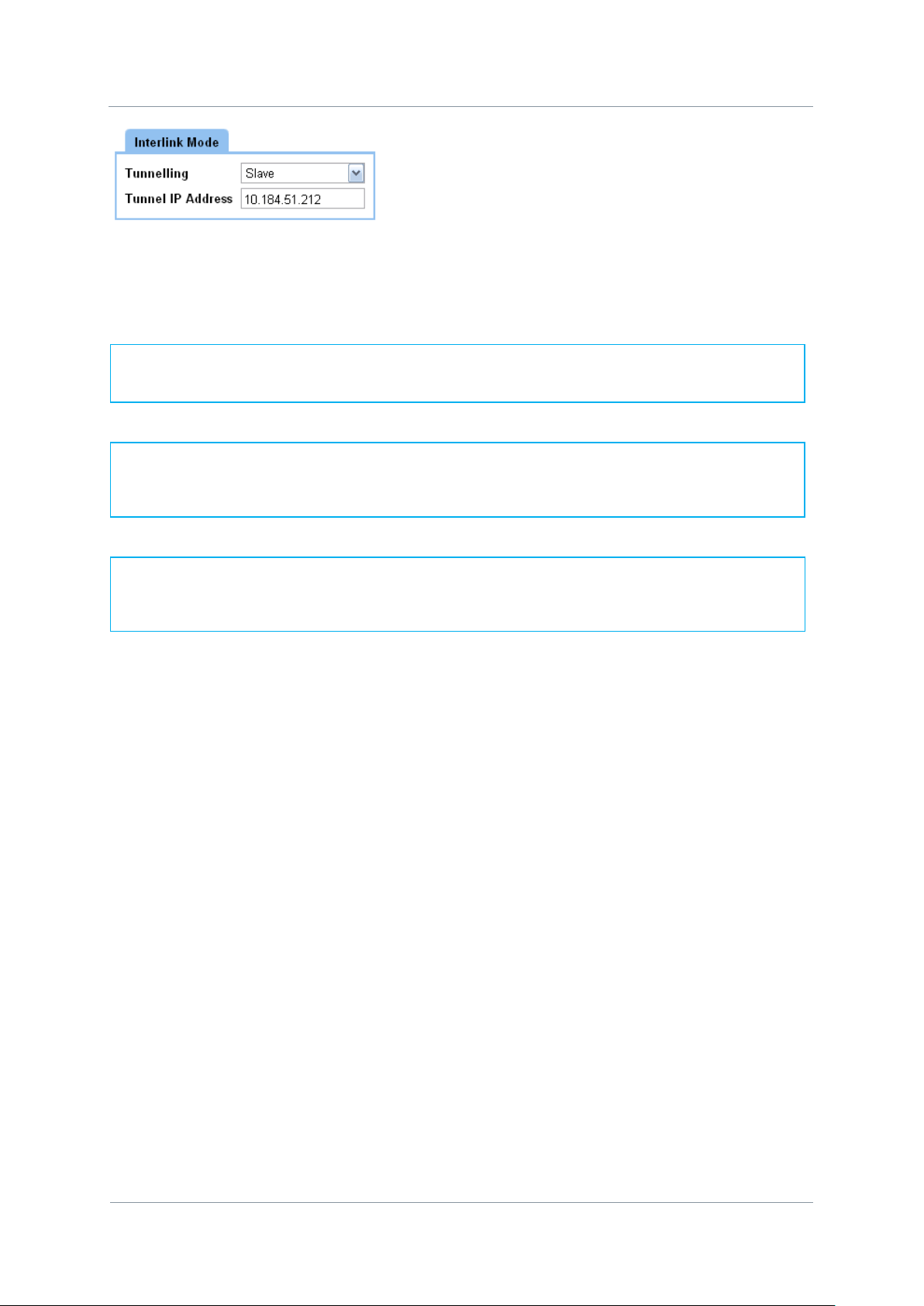
NETNode
Phase 1 and 2 Units
NETNode
User Manual
NETNode-V2.3
8-83
DS000034 Unclassified
Note: The Interlink NetNodes must always be linked via the radio interface, as well as
the IP backbone to operate correctly. This ensures the system remains as a single Mesh
Network.
Note: Do not connect a unit on the same Radio Network to the same IP backbone with
its Tunnel Mode set to Off. This will result in loss of functionality. First set the mode to
master or slave and then connect.
Note: All separate Mesh networks connected to the IP network (no matter where) must
have different Mesh ID‟s. Failure to do this will result in loss of functionality.
When all nodes have been configured they can all be connected to the common backbone.
You may need to wait unit 1min before the Mesh is accessible.
Page 93

NETNode
Phase 1 and 2 Units
NETNode
User Manual
NETNode-V2.3
9-84
DS000034 Unclassified
9. Mission Commander
Mission Commander is a multi-platform application which allows user to view the status of
the entire Mesh Network and other connected devices on a map based platform. An example
of its use is shown below.
The detailed description and features are outside of this document. Mission Commander is
available as a separate software product.
Page 94

NETNode
Phase 1 and 2 Units
NETNode
User Manual
NETNode-V2.3
10-85
DS000034 Unclassified
10. LED Indicators
10.1. NETNode Phase 1 Unit
10.1.1. Top Led
This lights green if power is applied to the unit.
10.1.2. Bottom Led
This lights green if the unit is successfully connected to other NETNode units in a Mesh.
10.2. NETNode Phase 2 Robust Unit
The LEDS are mounted behind a plastic „flip‟ cover. The position and function is identical to
the Phase 1 unit.
Page 95

NETNode
Phase 1 and 2 Units
NETNode
User Manual
NETNode-V2.3
10-86
DS000034 Unclassified
10.3. NETNode Phase 2 Plain Box Unit
The LEDS are mounted behind a plastic „flip‟ cover. The position and function is identical to
the Phase 1 unit.
The slot beside the LED allows a user to insert a SD card.
Page 96

NETNode
Phase 1 and 2 Units
NETNode
User Manual
NETNode-V2.3
11-87
DS000034 Unclassified
Pin No
Function
A
12 V B Ground
Pin No
Function
A
RS485 Tx+
B
RS485 Tx-
C
GND D RS485 Rx+
E
RS485 Rx-
F
GND
G
Engineering Use Only
H
Engineering Use Only
J
GND
K
RS232 Control TX
L
RS232 Control RX
M
GND N Radio Controller Trainer +
P
Radio Controller Trainer -
R
GND
S
Secondary Ethernet OP
T
Secondary Ethernet ON
U
Secondary Ethernet IP
V
Secondary Ethernet IN
Pin No
Function
A
Ethernet OP
B
Ethernet ON
C
Ethernet IP
D
Ethernet IN
11. Connector Pin Outs (Phase 1)
11.1. POWER – 2-way Female Amphenol Male Size 10
11.2. CTRL / DATA 19-way Female Amphenol Size 14
11.3. IP 4-way Female Amphenol Size 08
Page 97

NETNode
Phase 1 and 2 Units
NETNode
User Manual
NETNode-V2.3
11-88
DS000034 Unclassified
Pin No
Function
A
Audio Left
B
Ground Audio Left
C
Audio Right
D
Ground Audio Right
E
Ground
F
Composite / S-Video Luma
G
Video Ground
H
S-Video Chroma
J
Ground Chroma
K
Ground
11.4. AV 10-way Female Amphenol Size 12
Page 98

NETNode
Phase 1 and 2 Units
NETNode
User Manual
NETNode-V2.3
12-89
DS000034 Unclassified
Pin No
Function
1
12 V
2
12 V 3 GND 4 GND
Pin No
Function
1
TX
2
RX 3 GND
12. Connector Pin Outs (Phase 2 Plain
Box)
12.1. AV - 4-pin 0B LEMO Socket (TX and RX)
12.2. Data - 3-pin 0B LEMO Socket
Page 99

NETNode
Phase 1 and 2 Units
NETNode
User Manual
NETNode-V2.3
12-90
DS000034 Unclassified
Pin No
Function
1
RS485 TX+
2
RS485 TX-
3
GND 4 RS485 RX+
5
RS485 RX-
6
+12V
7
RS232 TX1
8
RS232 RX1
9
RS232 GND
10
RS232 TX2
11
RS232 RX2
12
RS232 GND
13
RC trainer +
14
RC trainer -
15
GND
Pin No
Function
1
Audio Right In
2
Audio Left In
3
GND 4 Composite In
5
GND
12.3. Aux 15-way Female High Density D-Type
12.4. RJ45 1 and 2
Standard RJ45 female 10/100 Base-T Connector
12.5. A/V Input - 5-pin 0B LEMO socket (Only with A/V
option)
Page 100

NETNode
Phase 1 and 2 Units
NETNode
User Manual
NETNode-V2.3
12-91
DS000034 Unclassified
Pin No
Function
1
Spare Talkback Audio In
2
Mic Talkback Audio In
3
Talkback Audio in GND
4
Talkback Audio Out 1
5
Talkback Audio Out 2
6
Talkback Audio Out GND
12.6. T/B - 6-pin 0B LEMO socket (G-key)
12.7. RF Connectors
1 SMA (f) Receive only
1 SMA (f) Transmit and Receive
 Loading...