

For the latest prices, please check AutomationDirect.com.
Do-more T1H Series PLC Overview
Do-more T1H Series
PLC
The T1H Series PLC takes the modular
and space-saving package of our
Terminator I/O line and converts it into
a stand-alone control system. Using
Do-more Designer as a foundation,
the T1H Series PLC system provides a
powerful, flexible instruction set, inside a
user friendly programming environment.
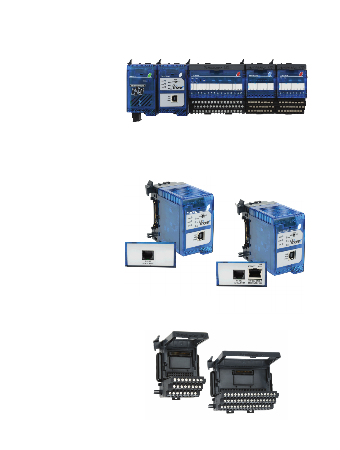
Do-more T1H PLC System with T1H-DM1E CPU Module
T1H-DM1
CPU modules
The Do-more T1H Series PLC offers two
CPU modules, T1H-DM1 and T1H-DM1E,
both of which must be programmed using
the Do-more Designer programming software version 1.2 or later.
T1H-DM1E
(with Ethernet)
Base units
The Do-more T1H Series PLC supports
all of the base units available for the
Terminator I/O line.
www.automationdirect.com/do-more-plcs
Do-more T1H PLCs
tDMT-1
For the latest prices, please check AutomationDirect.com.
Do-more T1H Series PLC Overview
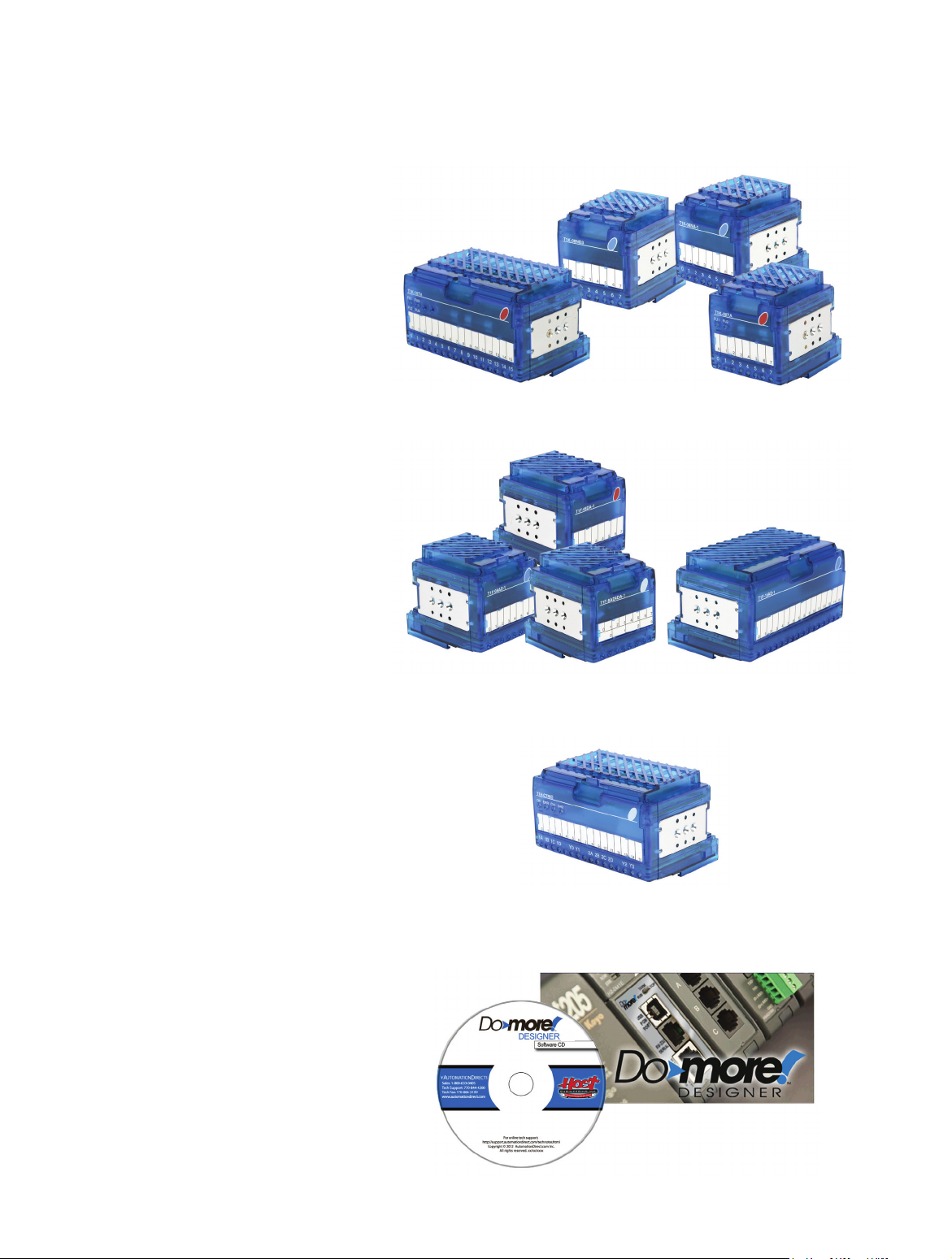
Discrete I/O modules
The Do-more T1H Series PLC supports all
of the discrete I/O modules available in
the Terminator I/O product line.
Analog I/O modules
The Do-more T1H Series PLC supports all
of the analog I/O modules available in
the Terminator I/O product line.
Specialty module
The Do-more T1H Series PLC supports
the T1H-CTRIO High-Speed Counter I/O
module that is available in the Terminator
I/O product line.
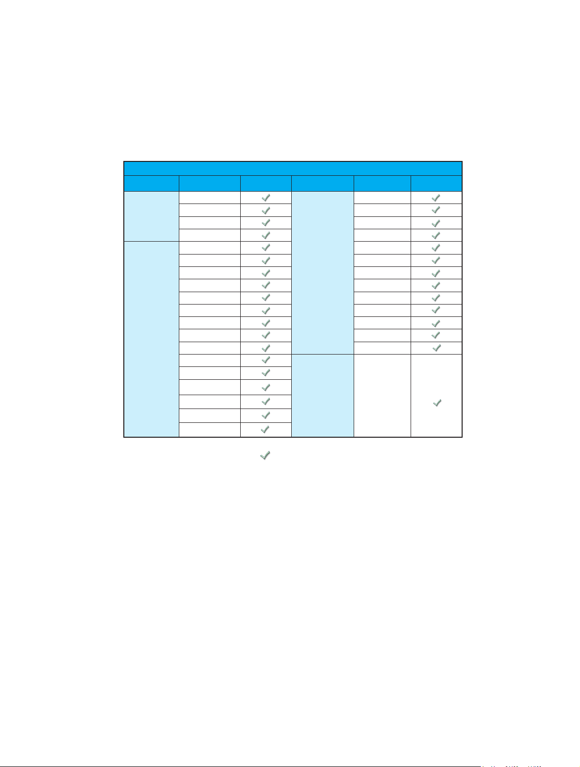
Programming Software
The Do-more T1H Series PLC can only
be programmed by Do-more Designer
version 1.2 or later.
T1H-CTRIO
1.2
tDMT-2
Do-more T1H PLCs
1-800-633-0405
For the latest prices, please check AutomationDirect.com.
Do-more T1H Series PLC Overview
Module Compatibility
The following table shows which Terminator I/O product line components are supported
by the T1H-DM1 and T1H-DM1E Do-more CPUs.
Module Compatibility Table
Module Part Number
T1K-08B
Base Units
Discrete I/O
Modules
T1K-08B-1 T1F-08AD-2
T1K-16B T1F-16AD-1
T1K-16B-1 T1F-16AD-2
T1K-08ND3 T1F-16RTD
T1K-16ND3 T1F-16TMST
T1K-08NA-1 T1F-14THM
T1K-16NA-1 T1F-08DA-1
T1K-08TD1 T1F-08DA-2
T1K-16TD1 T1F-16DA-1
T1K-08TD2-1 T1F-16DA-2
T1K-16TD2-1 T1F-8AD4DA-1
T1H-08TDS T1F-8AD4DA-2
T1K-08TA
T1K-16TA
T1K-08TAS
T1K-08TR
T1K-16TR
T1K-08TRS
Status Module Part Number Status
T1F-08AD-1
Analog I/O
Modules
Specialty
Module
T1H-CTRIO
= Supported
www.automationdirect.com/do-more-plcs
Do-more T1H PLCs
tDMT-3

For the latest prices, please check AutomationDirect.com.
Do-more T1H Series PLC Overview
Communications
The Do-more T1H Series PLC supports many communication protocols. The following table shows which CPU module
communications port supports each protocol.
CPU Modules
T1H-DM1 / T1H-DM1E T1H-DM1E
Protocols
Do-more Designer Programming
USB Port
Yes Yes Yes
RS-232
Serial Port
Ethernet
Port
Modbus/RTU Client (Master)
Modbus/RTU Server (Slave)
Modbus/TCP Client (Master)
Modbus/TCP Server (Slave)
DirectLOGIC RX/WX Client (Master)
DirectLOGIC RX/WX Server (Slave)
K-Sequence Server (Slave)
DirectNET Server (Slave)
HEI Ethernet I/O Master
SMTP (EMail) Client w/Authentication
Simple Network Time Protocol (SNTP) Client
Do-more/PEERLINK
Do-more Time Synchronization Protocol (Client, Server,
Alternate Client)
Do-more Logger/UDP
Serial ad-hoc ASCII/Binary Programatic Control
UDP ad-hoc Programmatic Control
Yes
Yes
Yes
Yes
Yes
Yes
Yes
Yes
Yes
Yes
Yes
Yes
Yes
Yes
Yes
tDMT-4
TCP Client Programmatic Control
TCP Server Programmatic Control
Do-more T1H PLCs
Yes
Yes
Blank = Not Supported
1-800-633-0405

For the latest prices, please check AutomationDirect.com.
Do-more T1H Series PLC Overview
Do-more T1H Series PLC Hardware User Manual (T1H-DM-M)
Do-more T1H Series PLC Hardware User Manual is available as a free download from Automationdirect.
com. A hard copy is also available for purchase.
Do-more Designer (Part No. DM-PGMSW)
Do-more Designer is the full-featured programming software for the
Do-more PLC series. Do-more Designer is a free download from
Automationdirect.com. A CD-ROM version is also available for
purchase for $11.00.
Start Page
When the software is started, the Start Page is
displayed. This page contains a Launchpad with
Projects, Applications and Links windows. It also
contains shortcuts to important help file topics, and
you can start the Do-more Simulator from this page.
1.2
Project
Toolbar
Project
Browser
Ladder
View
Launchpad
Do-more
Simulator
Help File
Shortcuts
Main Programming Window
The Main Programming Window is displayed
when a new project is started or an existing
project is opened. It is divided into Menus,
Toolbars, and Windows that work together to
make project development simple.
Ladder
Palette
Bar
www.automationdirect.com/do-more-plcs
Do-more T1H PLCs
tDMT-5

For the latest prices, please check AutomationDirect.com.
Do-more T1H Series PLC Overview
Do-more Designer Features
Do-more Designer has the following main features:
• Supports the Do-more PLC instruction set
• Project Browser (Window to organize the user project)
• Data View (Interface to monitor and edit PLC data in a list)
• Trend View (Interface to monitor PLC data with trend graphs)
• PID View (Interface to monitor and tune the individual PID control loop)
• PID Overview (Interface to monitor multiple PID control loops)
• Debug View (Interface to debug the ladder programs)
When Do-more Designer is installed on your PC, the following tools are also installed:
• Do-more Simulator (Offline simulator of ladder program execution and PID control)
• Do-more Logger (Software tool to log PLC data)
• ERM Workbench (Configuration tool for the ERM modules)
• NetEdit 3 (Configuration tool for the ECOM/EBC Ethernet modules)
PC Requirements
The Do-more Designer Windows-based programming software works with Windows®
XP (Home or Professional, 32-bit), Vista (Home, Basic, Premium, 32 or 64-bit),
Windows 7 (Home, Professional, Ultimate, 32 or 64-bit) or Windows 8 (Home,
Professional, Enterprise 32 or 64-bit; Windows 8 RT edition is NOT supported).
Please check the following requirements when choosing your PC configuration:
• Minimum PC to PLC Connectivity, at least one of the following:
- USB Port: connects to the CPU with USB-A connector (USB-A to USB-B cable)
- RS-232 Serial Port: connects to the CPU with RJ-12 connector (RJ-12 to DB9 or RJ-12 to USB-B
serial converter cable)
- Ethernet Port: connects to the CPU (T1H-DM1E) with RJ-45 10Base-T or 100Base-T
(Cat5 Patch Cable)
• Hard Disk: 100MB free disk space
• Video Display: 1024x768, 256 colors resolution (1280x720, true color recommended)
• Windows XP, 32-bit:
- 800MHz, single core CPU (2GHz, multi-core or hyperthreaded recommended)
- 512MB RAM (2GB recommended)
• Vista or Windows 7 or Windows 8, 32 or 64-bit:
- 1GHz, single core CPU (2GHz, multi-core recommended)
- 1GB RAM (3GB recommended)
Programming Cables
The Do-more T1H Series CPU module T1H-DM1 has two communication ports (USB
and RS-232 Serial) and the T1H-DM1E has three communication ports (USB, RS-232
Serial and Ethernet). You can use any of those ports for programming and monitoring.
Cables for these ports are listed below and can be purchased at Automationdirect.com.
USB Cables (USB 2.0, Type A-B connectors):
• USB-CBL-AB3 (3 ft.)
• USB-CBL-AB6 (6 ft.)
• USB-CBL-AB10 (10 ft.)
• USB-CBL-AB15 (15 ft.)
RS232 Serial Cable
• D2-DSCBL (12 ft. 9-pin D-sub to RJ12 connector)
Ethernet Cables (Cat5e)
Automationdirect.com sells many Ethernet patch cables in various colors and lengths. Please check
the Cables section in this catalog for further details.
tDMT-6
Do-more T1H PLCs
1-800-633-0405

For the latest prices, please check AutomationDirect.com.
Do-more T1H Series PLC Overview
Do-more PLC Instruction Set
This Instruction Set was developed specifically for the new Do-more PLC series; the
‘Instruction Palette’ displays all available
instructions.
You may see some similarities to the
DirectLOGIC PLC instruction set. However,
the instruction set for the Do-more PLC is
more advanced and intuitive. A good example
is the MATH instruction. Now, just one MATH
instruction covers all math operations and
also allows you to mix different data types in
one expression.
There are over 60 operators and functions
available with the MATH instruction.
Note: To learn more about the MATH instruction, please refer to the Do-more Designer
help topic ‘MATH – Calculate Expression’.
Operators
+, -, *, /, %, **, <, <=, ==, !=, >=, >, &&, ||, &, |, ^, <<, >>, >>>, -, ~, !
Funcons
ABS, ACOS, ASIN, ATAN, AVGR, COS, COUNTIFEQ, COUNTIFNE,
COUNTIFGE, COUNTIFGT, COUNTIFLE, COUNTIFLT, DEG, E, FRAC, IF,
LN, LOG, MAXR, MAX, MINR, MIN, NOW PI, ,
REF, ROUND, SIN, SQRT, STDEVR, STDEVPR, SUMIFEQ, SUMIFNE,
SUMIFGE, SUMIFGT, SUMIFLE, SUMIFLT, SUMR, TAN, TICKms,
TICKus, TOINT, TOREAL, TRUNC
RAD, RANDINT, RANDREAL,
www.automationdirect.com/do-more-plcs
Do-more T1H PLCs
tDMT-7

For the latest prices, please check AutomationDirect.com.
Do-more T1H Series PLC Overview
Data Types
The Do-more PLC supports the following seven primary data types:
• Bit (0 or 1)
• Unsigned Byte (0 to 255)
• Signed Byte (-128 to 127)
• Unsigned Word (0 to 65,535)
• Signed Word (-32,768 to 32,767)
• Signed DWord (-2,147,483,648 to 2,147,483,647)
• Real (-3.4028235E+038 to 3.4028235E+038)
Data Structures
The Do-more PLC supports data structures as additional data types. Structures use the
familiar PC programming organization of “dot notation”. All available elements of a
structure are shown in this format. The following data structures are currently available:
• Timer Structure
• Counter Structure
• String Structure
• PID Structure
• Date/Time Structure
• Task Structure
• Rampsoak Structure
• Program Structure
• DeviceRef Structure
• Drum Structure
The data structure is a set of data. For instance, a Timer structure (Timer Struct) has the
following set of data:
• Acc (Accumulated Time, Signed DWord)
• Done (Bit)
• Zero (Bit)
• Timing (Bit)
• Reset (Bit)
When you use a timer instruction (TMR), a Timer structure is assigned to the instruction. If
you select ‘T0’, you can access the above data with dot notation. For instance, to access
the accumulated time (Acc), enter ‘T0.Acc’. To access the Done bit, enter ‘T0.Done’.
• Stream Structure
• SIM_Process Structure
• Server Structure
• Peerlink Structure
• I/O_Master Structure
• Eth_IO_Master Structure
• GS Drive Structure
• Packet Structure
Memory Addressing
With the Do-more PLC, each memory address type has its own specific data type. Here
are some examples:
• V (Unsigned Word)
• N (Signed Word)
• D (Signed DWord)
• R (Real)
If you see address ‘V123’ in the ladder program, the memory address always stores an
Unsigned Word value. With this memory addressing method, it becomes easier to read
and write the ladder programs.
Although most of the memory addressing is decimal, the memory addresses DLX, DLY,
DLC and DLV use octal. These four memory address types can be used to exchange data
with DirectLOGIC PLCs, which use octal memory addressing.
tDMT-8
Do-more T1H PLCs
1-800-633-0405

For the latest prices, please check AutomationDirect.com.
Do-more T1H Series PLC Overview
Array Addressing
The Do-more PLC supports one-dimensional array addressing with all memory
addresses. A V-memory address must be used as the index for an array. With the
Do-more PLC, the following ladder program is valid.
Note: In this example, V0, V100, V101, V102 and V200 are indices.
Code-block, Program and Task
One Do-more project can consist of more than one ladder program. Each ladder
program is called a ‘Code-block’. The Do-more PLC supports two types of code-blocks,
Program and Task:
Program
Programs are code-blocks that run based on an event using the RUN instruction. They
can be self-terminating or never terminate. Stage programming is only supported inside
Program code-blocks.
Task
Tasks are code-blocks that are enabled and disabled using the ENTASK instruction. The
ENTASK instruction allows you to specify an interval to execute the task’s logic with a
millisecond resolution or to execute a single time on a leading edge input.
Stages
The Do-more PLC supports Stages. You can use Stages only in the Program code-blocks.
(They are not available in the Task code-blocks.) The Do-more PLC supports the following
instructions for Stage Programming1:
• SG (Stage)
• JMP (Jump To Stage)2
• JMPI (Index Jump)
• SGSET (Enable Stage)
• SGRST (Disable Stage)
• SGRSTR (Disable Range of Stages)
• SGCONVRG (Converge Multiple Stages to SG)
• SGDIVRG (Jump to Multiple Stages)
1 There is no ISG (Initial Stage) instruction for the Do-more PLC; the first stage in the Program code-
block becomes the initial stage automatically.
2 Many asynchronous instructions can directly initiate a Jump to Stage.
www.automationdirect.com/do-more-plcs
Do-more T1H PLCs
tDMT-9
 Loading...