

SpecificationS:
Chapter
Chapter
Chapter
DiScrete i/o MoDuleS
5
5
1
In This Chapter...
Discrete I/O Modules Overview ................................................................................ 5–3
Discrete Input Modules ............................................................................................5–3
Discrete Output Modules .........................................................................................5–4
Discrete Input/Output Module ................................................................................. 5–4
D2-08ND3, DC Input .................................................................................................5–5
D2-16ND3-2, DC Input .............................................................................................. 5–6
D2–32ND3, DC Input ................................................................................................. 5–7
D2–32ND3–2, DC Input ............................................................................................. 5–8
D2–08NA-1, AC Input ................................................................................................5–9
D2-08NA-2, AC Input ............................................................................................... 5–10
D2-16NA, AC Input .................................................................................................. 5–11
D2-04TD1, DC Output ............................................................................................. 5–12
D2–08TD1, DC Output ............................................................................................5–13
D2–08TD2, DC Output ............................................................................................5–14
D2–16TD1–2, DC Output ......................................................................................... 5–15
D2–16TD2–2, DC Output ......................................................................................... 5–16
F2–16TD1P, DC Output With Fault Protection ......................................................5–17
F2–16TD2P, DC Output with Fault Protection ........................................................ 5–19
D2–32TD1, DC Output ............................................................................................5–21
D2–32TD2, DC Output ............................................................................................5–22
F2–08TA, AC Output ................................................................................................5–23
D2–08TA, AC Output ..............................................................................................5–24
D2–12TA, AC Output ...............................................................................................5–25

Table of Contents
D2–04TRS, Relay Output .........................................................................................5–26
1
2
3
4
5
6
7
8
9
10
11
D2–08TR, Relay Output ...........................................................................................5–27
F2–08TR, Relay Output ............................................................................................ 5–28
F2–08TRS, Relay Output ..........................................................................................5–29
D2–12TR, Relay Output ...........................................................................................5–30
D2–08CDR, 4 pt. DC Input / 4pt. Relay Output .....................................................5–31
12
13
14
A
B
C
D
5–2
Do-more H2 Series PLC Hardware User Manual, 1st Edition, Rev. I - H2-DM-M
Chapter 5: Specifications - Discrete I/O Modules
C
5
6
7
0
3
10
C
4
A
C
3
IN
1
4
VDC
1
2
3
5
6
Discrete I/O Modules Overview
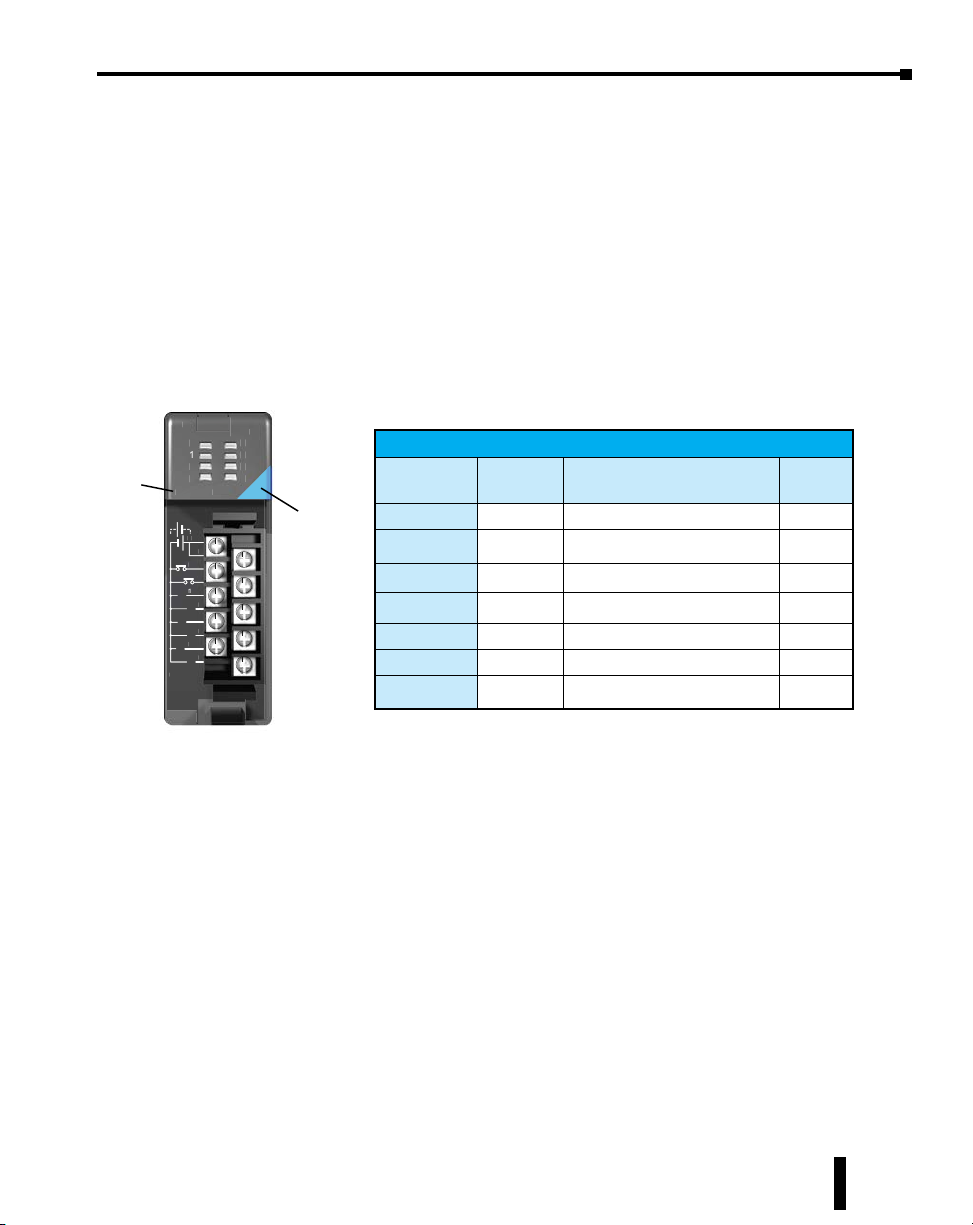
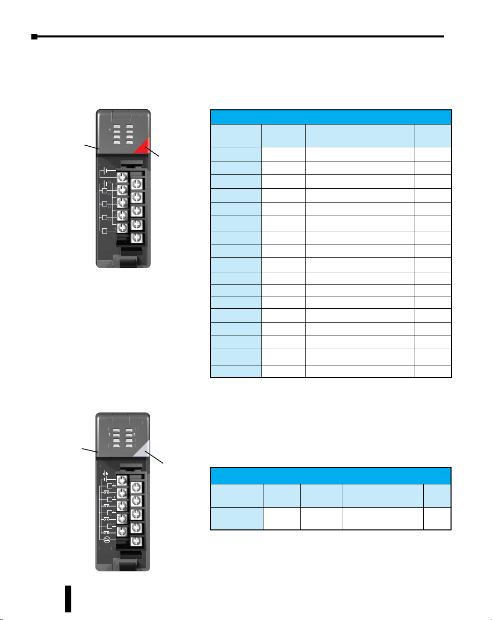
There are 25 discrete I/O modules available for use in local and remote I/O bases. The
specifications and wiring diagrams for these modules are found in this chapter. Each discrete
I/O module is identified as an “Input”, “Output” or “Input/Output” module using the color
coding scheme shown below. A blue bar on the front panel signifies an Input I/O module, a red
bar signifies an Output I/O module and a White bar signifies a combination Input/Output
module.
Discrete Input Modules
Module
Part Number
IN 12-24
0
0
1
2
3
D2-08ND3
D2-08ND
C
C
0
4
1
5
2
6
3
7
10.2-26.4VDC
.2-26.4VD
4-12mA
-12m
VDC
2-2
4
5
6
7
Module Type
(Blue: Input)
Part Number
D2-08ND3
D2-16ND3-2
D2-32ND3
D2-32ND3-2
D2-08NA-1
D2-08NA-2
D2-16NA
Discrete Input Modules
Number of
Inputs
8 Sinking/Sourcing DC Input 5-4
16 Isolated Sinking/Sourcing DC Input 5-5
32 Isolated Sinking/Sourcing DC Input 5-6
32 Isolated Sinking/Sourcing DC Input 5-7
8 AC Input 5-8
8 AC Input 5-9
16 Isolated AC Input 5-10
Description See Page
Do-more H2 Series PLC Hardware User Manual, 1st Edition, Rev. I - H2-DM-M
5–3
Chapter 5: Specifications - Discrete I/O Modules
0
1
2
3
C
C
C
C
C
1
T
12-24
VDC
0
1
2
3
C
50
3
CB
0
2
3
L
08C
IN/
OUT
2
/
RELAY
0
1
2
3
A
CA
0
L
0
1
2
3
B
20-28VDC
5
C
1
5-30VDC
5
A
Discrete I/O Modules Overview, continued
Discrete Output Modules
OUT12-24
Module
Part Number
OU
0
1
2
3
D2-04TD1
D2-04TD
10.2-26.4VDC
10.2-26.4VD
mA-2A
50mA-2A
+24V
+24V
C
L
C
L
C
L
C
L
VDC
Part Number
Module Type
C
0
1
2
3
(Red: Output)
D2-04TD1
D2-08TD1
D2-08TD2
D2-16TD1-2
D2-16TD2-2
F2-16TD1P
F2-16TD2P
D2-32TD1
D2-32TD2
F2-08TA
D2-08TA
D2-12TA
D2-04TRS
D2-08TR
F2-08TR
F2-08TRS
D2-12TR
Discrete Output Modules
Number of
Outputs
4 Sinking Output 5-11
8 Sinking Output 5-12
8 Sourcing Output 5-13
16 Sinking Output 5-14
16 Sourcing Output 5-15
16 Protected Sinking Output 5-16
16 Protected Sourcing Output 5-18
32 Sinking Output 5-20
32 Sourcing Output 5-21
8 AC Output 5-22
8 AC Output 5-23
12 AC Output 5-24
4
8 Relay Output 5-26
8 Relay Output 5-27
8 Isolated Relay Output 5-28
12 Relay Output 5-29
Description See Page
Isolated Relay Output 5-25
5–4
Discrete Input/Output Module
4VDC
IN/
24VDC/
OUT
RELAY
A
Module
Part Number
D2-08CDR
D2-
20-28VDC
-240VA
5-240VAC
A 50/60Hz
1A 50/60Hz
5-30VDC
mA-1
5mA-1A
Do-more H2 Series PLC Hardware User Manual, 1st Edition, Rev. I - H2-DM-M
B
0
0
1
1
2
2
3
3
DR
8mA
8mA
CA
0
L
0
1
L
1
1
2
L
2
3
L
3
CB
Module Type
(White: Input/Output)
Part Number
D2-08CDR
Discrete Input/Output Modules
Number
of Inputs
Number of
Outputs
4 4
Sinking/Sourcing DC Input
Description
with Relay Output
See
Page
5-30
Chapter 5: Specifications - Discrete I/O Modules
C
F
P
d
D
Sink
Sou
C
5
6
7
0
3
10
C
4
A
C
3
IN
4
C
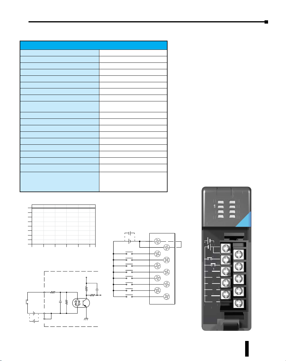
D2-08ND3, DC Input
D2-08ND3 DC Input
Inputs per Module
Commons per Module
Input Voltage Range
Peak Voltage
ON Voltage Level
OFF Voltage Level
AC Frequency
Input Impedance
Input Current
Minimum ON Current
Maximum OFF Current
Base Power Required 5VDC
OFF to ON Response
ON to OFF Response
Terminal Type (included)
Status Indicator
Weight
ZIPLink Module
ZIPLink Cable
o i n t s
8
6
4
2
0
0
3 2
+
rce
-
12-- 24VDC
D e r a t i n g C h a r t
1 0 2 0 3 0 4 0 5 0 5 5
5 0 6 8 8 6 1 0 4 1 2 2 1 3 1
A m b i e n t T e m p e r a t u r e ( ° C / ° F )
INPUT
COM
-
COM
+
Internal module circuitry
8 (sink/source)
1 (2 I/O terminal points)
10.2-26.4 VDC
26.4 VDC
9.5 VDC minimum
3.5 VDC maximum
N/A
2.7 kq
4.0 mA @ 12VDC
8.5 mA @ 24VDC
3.5 mA
1.5 mA
50mA
1 to 8 ms
1 to 8 ms
Removable, D2-8IOCON
Logic side
2.3 oz. (65g)
ZL-RTB20 (Feedthrough)
ZL-D2-CBL10 (0.5m)
ZL-D2-CBL10-1 (1.0m)
ZL-D2-CBL10-2 (2.0m)
°
°
V+
To LE
Optical
Isolator
Source
Sink
12-- 24VDC
-
-
+
IN 12-24
0
0
1
2
3
D2-08ND3
D2-08ND
+
C
0
1
2
3
Internally
connecte
C
4
5
6
7
10.2-26.4VDC
.2-26.4VD
4-12mA
-12m
C
C
0
4
1
5
2
6
3
7
2-2
VDC
D
4
5
6
7
Do-more H2 Series PLC Hardware User Manual, 1st Edition, Rev. I - H2-DM-M
5–5
C
F
P
+
-
24
Source
24
D
Sink
Sou
Chapter 5: Specifications - Discrete I/O Modules
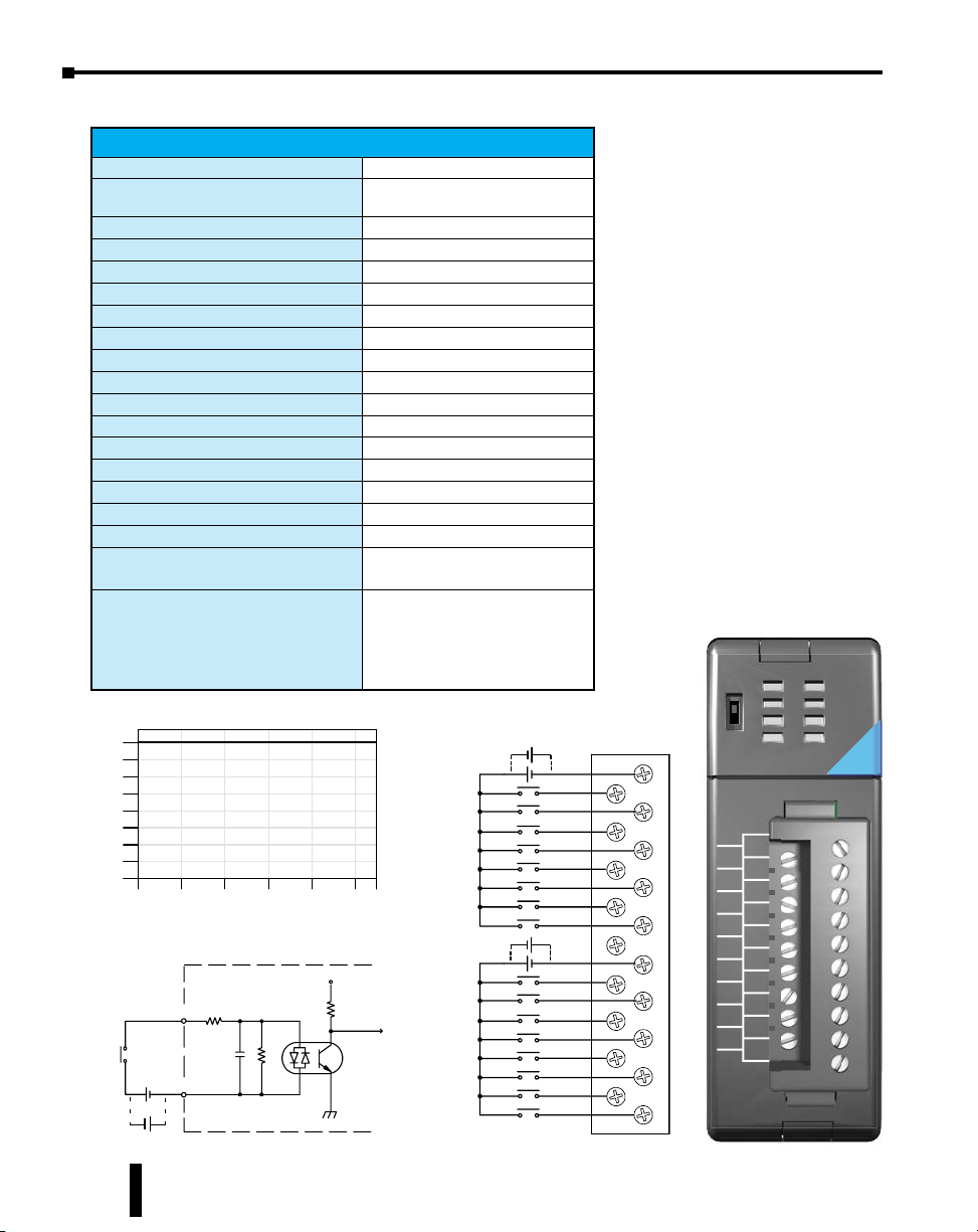
D2-16ND3-2, DC Input
D2-16ND3-2 DC Input
Inputs per Module
Commons per Module
Input Voltage Range
Peak Voltage
ON Voltage Level
OFF Voltage Level
AC Frequency
Input Impedance
Input Current
Minimum ON Current
Maximum OFF Current
Base Power Required 5VDC
OFF to ON Response
ON to OFF Response
Terminal Type (included)
Status Indicator
Weight
ZIPLink Module
ZIPLink Cable
o i n t s
8
6
4
5–6
2
0
0
3 2
-
+
rce
-
24 VDC
Do-more H2 Series PLC Hardware User Manual, 1st Edition, Rev. I - H2-DM-M
D e r a t i n g C h a r t
1 0 2 0 3 0 4 0 5 0 5 5
5 0 6 8 8 6 1 0 4 1 2 2 1 3 1
A m b i e n t T e m p e r a t u r e ( ° C / ° F )
Internal modulecir cuit ry
INPUT
COM
+
16 (sink/source)
2 isolated (8 I/O terminal points/com)
20–28 VDC
30VDC (10mA)
19VDC minimum
7VDC maximum
N/A
3.9 kq
6mA @ 24VDC
3.5 mA
1.5 mA
100mA
3 to 9 ms
3 to 9 ms
Removable, D2-16IOCON
Logic side
2.3 oz. (65g)
ZL-RTB20 (Feedthrough)
ZL-LTB16-24 (Sensor Input)
ZL-D2-CBL19 (0.5 m)
ZL-D2-CBL19-1 (1.0 m)
ZL-D2-CBL19-2 (2.0 m)
ZL-D2-CBL19-1P (1.0 m Pigtail)
ZL-D2-CBL19-2P (2.0 m Pigtail)
°
°
V+
To LE
Optical
Isolator
VDC
VDC
Sink
Source
Sink
IN
0
A
1
2
B
-
+
-
+
-
+
CA
0
4
1
5
2
6
3
7
NC
CB
0
4
1
5
2
6
3
7
3
D2-1 6ND3-2
20-28VDC
8mA
CA
0
4
1
5
2
6
3
7
NC
CB
0
4
1
5
2
6
3
7
24
VDC
4
5
6
7
Chapter 5: Specifications - Discrete I/O Modules
24V
Po
C
F
c
Sink
Sou
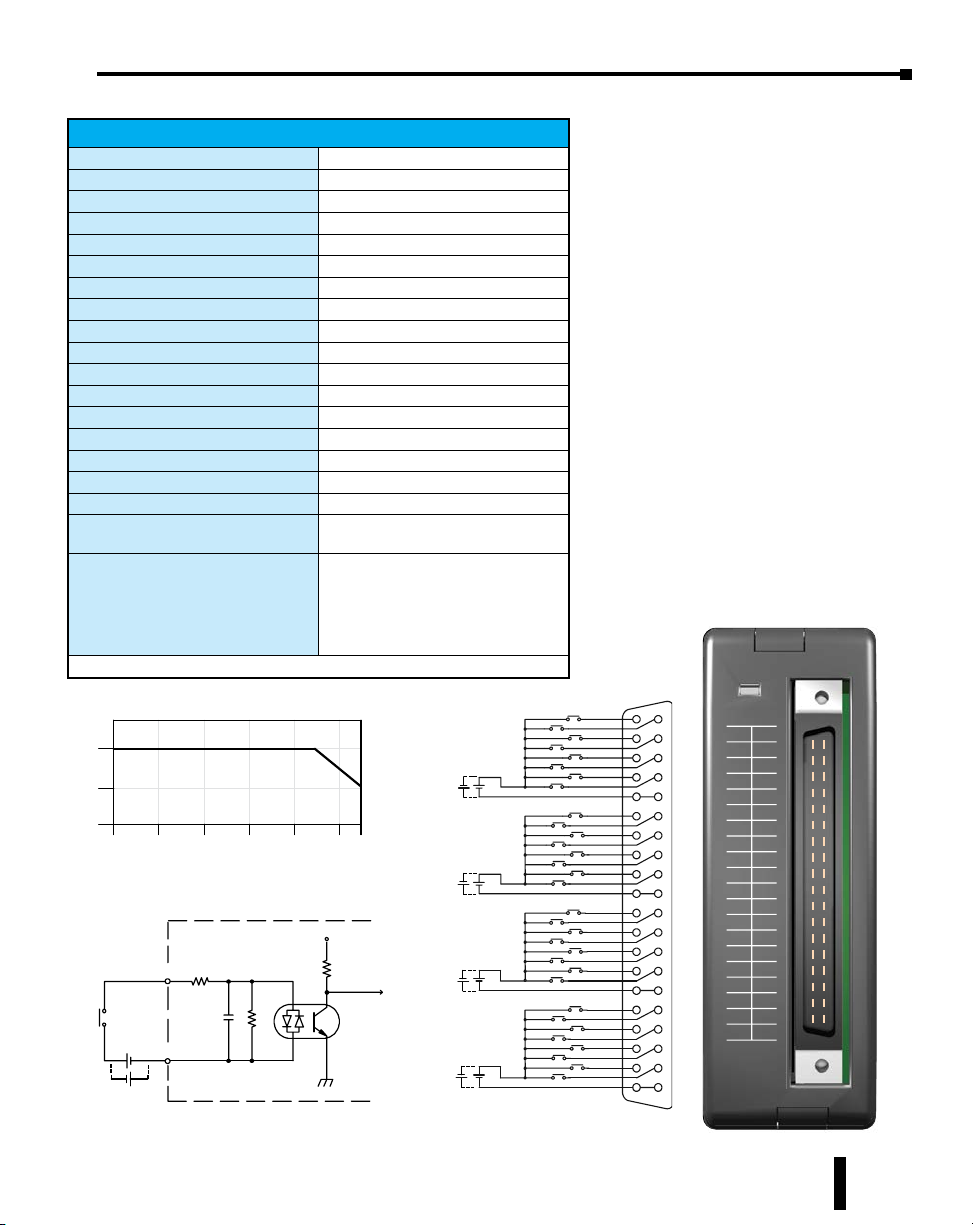
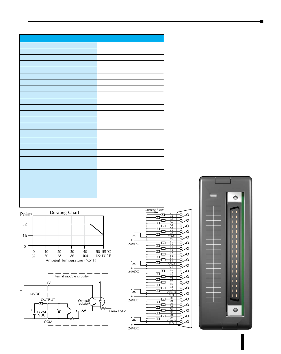
D2–32ND3, DC Input
D2-32ND3 DC Input
Inputs per Module
Commons per Module
Input Voltage Range
Peak Voltage
ON Voltage Level
OFF Voltage Level
AC Frequency
Input Impedance
Input Current
Minimum ON Current
Maximum OFF Current
Base Power Required 5VDC
OFF to ON Response
ON to OFF Response
Terminal Type (not included)
Status Indicator
Weight
ZIPLink Module
ZIPLink Cable
ZIPLink connector is recommended or purchase custom connector separately.
32 (sink/source)
4 isolated (8 I/O terminal points / com)
20–28 VDC
30VDC
19VDC minimum
7VDC maximum
N/A
4.8 kq
8.0 mA @ 24VDC
3.5 mA
1.5 mA
25mA
3 to 9 ms
3 to 9 ms
Removable 40-pin Connector
1
Module Activity LED
2.1 oz. (60g)
ZL-RTB40 (Feedthrough)
ZL-LTB32-24 (Sensor Input)
ZL-D24-CBL40 (0.5 m)
ZL-D24-CBL40-1 (1.0 m)
ZL-D24-CBL40-2 (2.0 m)
ZL-D24-CBL40-1P (1.0 m Pigtail)
ZL-D24-CBL40-2P (2.0 m Pigtail)
IN
ACT
24
VDC
A0
COMI
COMII
COMIII
COMIV
A4
A1
A5
A2
A6
A3
A7
B0
B4
B1
B5
B2
B6
B3
B7
C0
C4
C1
C5
C2
C6
C3
C7
D0
D4
D1
D5
D2
D6
D3
D7
ints
32
16
Derating Chart
24VDC
Source
Sink
+
-
+
-
0
V+
To Logi
Optical
Isolator
°
°
24VDC
24VDC
DC
Source
Source
Source
Sink
+
-
+
-
Sink
+
-
+
-
Sink
+
-
+
-
rce
10 20 30 40 50 55
0
50 68 86 104122 131
32
AmbientTemperature (°C/°F )
Internal module circuitry
INPUT
-
+
COM
+
-
24 VDC
Do-more H2 Series PLC Hardware User Manual, 1st Edition, Rev. I - H2-DM-M
D2-32ND3
A0
A4
A1
A5
A2
A6
A3
A7
CI
CI
B0
B4
B1
B5
B2
B6
B3
B7
CII
CII
C0
C4
C1
C5
C2
C6
C3
C7
CIII
CIII
D0
D4
D1
D5
D2
D6
D3
D7
CIV
CIV
22-26VDC
4-6mA
CLASS2
5–7
Chapter 5: Specifications - Discrete I/O Modules
24 VDC
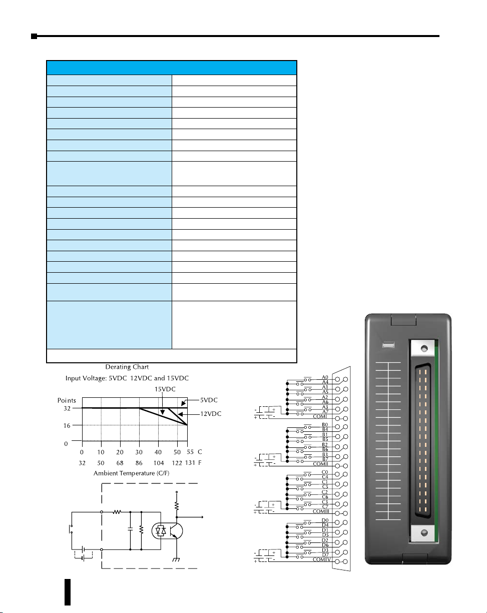
D2–32ND3–2, DC Input
D2-32ND3-2 DC Input
Inputs per Module
Commons per Module
Input Voltage Range
Peak Voltage
ON Voltage Level
OFF Voltage Level
AC Frequency
Input Impedance
Input Current
Maximum Input Current
Minimum ON Current
Maximum OFF Current
Base Power Required 5VDC
OFF to ON Response
ON to OFF Response
Terminal Type (not included)
Status Indicator
Weight
ZIPLink Module
ZIPLink Cable
ZIPLink connector is recommended or purchase custom connector separately.
,
Internal module circuitry
INPUT
-
+
Sink
Source
COM
+
-
32 (Sink/Source)
4 isolated (8 I/O terminal points / com)
4.50 to 15.6 VDC min. to max.
16VDC
4VDC minimum
2VDC maximum
N/A
1.0 kq @ 5–15 VDC
4mA @ 5VDC
11mA @ 12VDC
14mA @ 15VDC
16mA @ 15.6 VDC
3mA
0.5 mA
25mA
3 to 9 ms
3 to 9 ms
Removable 40-pin connector
1
Module activity LED
2.1 oz (60g)
ZL-RTB40 (Feedthrough)
ZL-LTB32-24 (Sensor Input)
ZL-D24-CBL40 (0.5 m)
ZL-D24-CBL40-1 (1.0 m)
ZL-D24-CBL40-2 (2.0 m)
ZL-D24-CBL40-1P (1.0 m Pigtail)
ZL-D24-CBL40-2P (2.0 m Pigtail)
5-15VDC
Source
°
°
5-15VDC
Source
V+
5-15VDC
Source
5-15VDC
Source
To Logic
Optical
Isolator
IN
ACT
5-15
VDC
D2-32ND3-2
A0
A4
A1
A5
A2
A6
A3
A7
CI
Sink
Sink
Sink
Sink
B0
B1
B2
B3
CII
C0
C1
C2
C3
CIII
D0
D1
D2
D3
CIV
5-15VDC
4-14mA
CLASS2
CI
B4
B5
B6
B7
CII
C4
C5
C6
C7
CIII
D4
D5
D6
D7
CIV
5–8
Do-more H2 Series PLC Hardware User Manual, 1st Edition, Rev. I - H2-DM-M
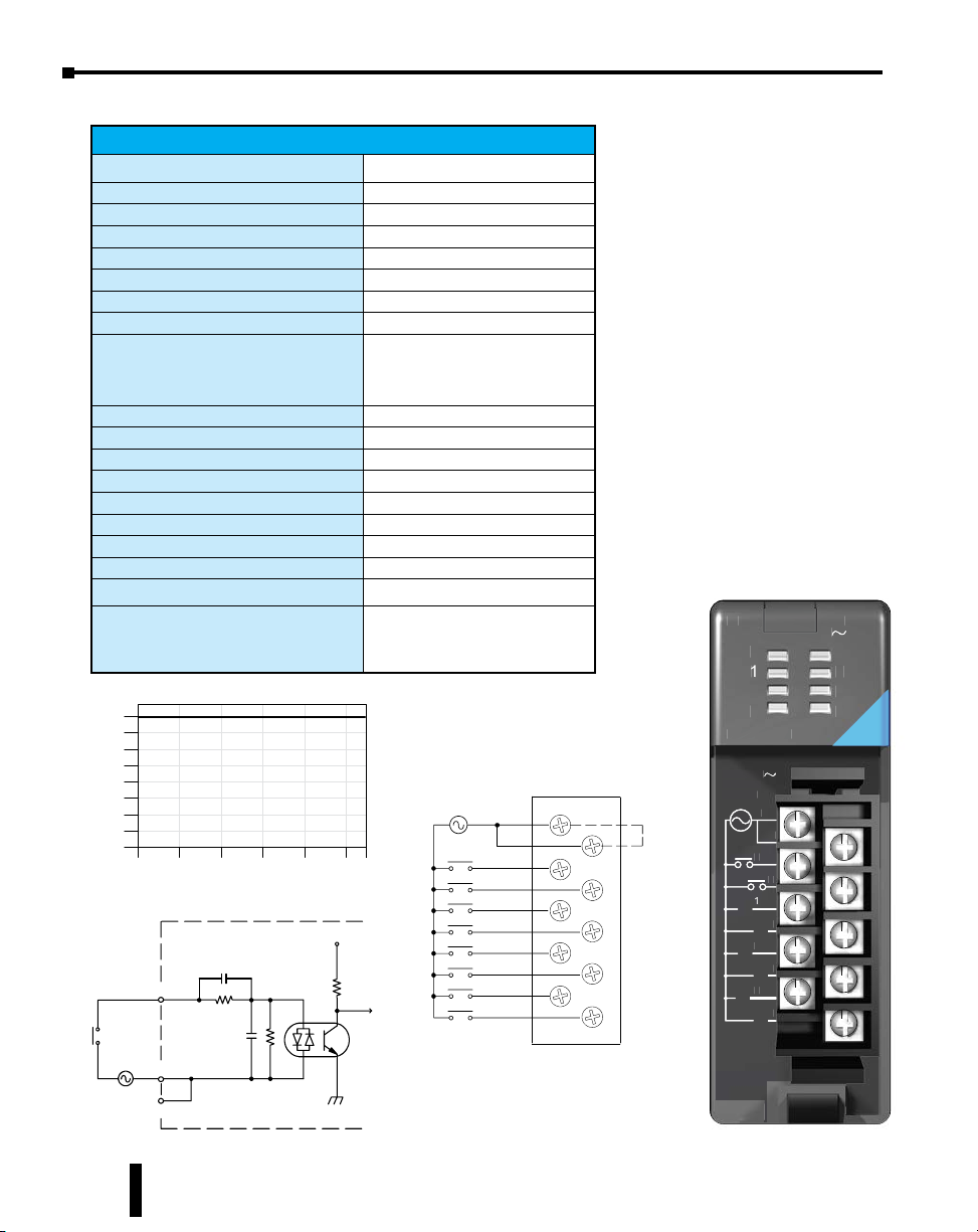
D2–08NA-1, AC Input
AmbientTemperature (°C/°F )
C
F
Derating Chart
ed
D
Li
C
z
D2-08NA-1 AC Input
Inputs per Module
Commons per Module
Input Voltage Range
Peak Voltage
ON Voltage Level
OFF Voltage Level
AC Frequency
Input Impedance
Input Current
Minimum ON Current
Maximum OFF Current
Base Power Required 5VDC
OFF to ON Response
ON to OFF Response
Terminal Type (included)
Status Indicator
Weight
ZIPLink Module
ZIPLink Cable
Points
8
6
4
2
0
ne
10 20 30 40 50 55
0
50 68 86 104 122 131
32
Internal module circuitry
INPUT
COM
110VAC
COM
8
1 (2 I/O terminal points)
80–132 VAC
132VAC
75VAC minimum
20VAC maximum
47–63 Hz
12kq @ 60Hz
13mA @ 100VAC, 60Hz
11mA @ 100VAC, 50Hz
5mA
2mA
50mA
5 to 30 ms
10 to 50 ms
Removable; D2-8IOCON
Logic side
2.5 oz. (70g)
ZL-RTB20 (Feedthrough)
ZL-D2-CBL10 (0.5 m)
ZL-D2-CBL10-1 (1.0 m)
ZL-D2-CBL10-2 (2.0 m)
V+
To LE
Optical
Isolator
Chapter 5: Specifications - Discrete I/O Modules
IN 11 0
0
1
2
3
D2-08NA-1
2-08NA-1
4
5
6
7
C
Internally
connect
8-132VAC
8-132VA
-20mA
10-20mA
H
50/60Hz
C
0
1
2
3
110VAC
°
°
C
0
1
2
3
VAC
VAC
4
5
6
7
C
4
5
6
7
5–9
Do-more H2 Series PLC Hardware User Manual, 1st Edition, Rev. I - H2-DM-M
Chapter 5: Specifications - Discrete I/O Modules
AmbientTemperature (°C/°F )
Derating Chart
D
238V
A
z
2
0
D2-08NA-2, AC Input
D2-08NA-2 AC Input
Inputs per Module
Commons per Module
Input Voltage Range
Peak Voltage
ON Voltage Level
OFF Voltage Level
AC Frequency
Input Impedance
Input Current
Minimum ON Current
Maximum OFF Current
Base Power Required 5VDC
OFF to ON Response
ON to OFF Response
Terminal Type (included)
Status Indicator
Weight
ZIPLink Module
ZIPLink Cable
Points
8
6
4
2
0
10 20 30 40 50 55
0
50 68 86 104 122 131C°F°
32
Internal module circuitry
INPUT
8
1 (2 I/O terminal points)
170–265 VAC
265VAC
150VAC minimum
40VAC maximum
47–63 Hz
18kq @ 60 Hz
9mA @ 220VAC, 50Hz
11mA @ 265VAC, 50Hz
10mA @ 220VAC, 60Hz
12mA @ 265VAC, 60Hz
10mA
2mA
100mA
5 to 30 ms
10 to 50 ms
Removable; D2-8IOCON
Logic side
2.5 oz. (70g)
ZL-RTB20 (Feedthrough)
ZL-D2-CBL10 (0.5 m)
ZL-D2-CBL10-1 (1.0 m)
ZL-D2-CBL10-2 (2.0 m)
220VAC
V+
To LE
IN 220
0
1
2
3
D2-08NA-2
-08NA-
187-238V
7-
10-20m
10-20mA
0/60H
C
C
Internally
0
connected
4
1
5
2
6
3
7
50/60Hz
C
C
0
4
1
5
2
6
3
7
7
2
V
4
5
6
7
5–10
COM
220VAC
COM
Do-more H2 Series PLC Hardware User Manual, 1st Edition, Rev. I - H2-DM-M
Optical
Isolator
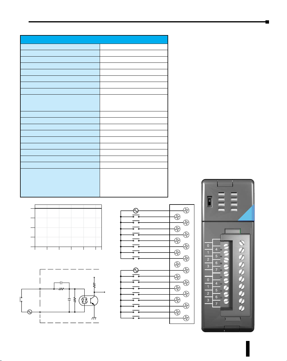
D2-16NA, AC Input
AmbientTemperature (°C/°F)
Derating Chart
110VAC
D
Inputs per Module
Commons per Module
Input Voltage Range
Peak Voltage
ON Voltage Level
OFF Voltage Level
AC Frequency
Input Impedance
Input Current
Minimum ON Current
Maximum OFF Current
Base Power Required 5VDC
OFF to ON Response
ON to OFF Response
Terminal Type (included)
Status Indicator
Weight
ZIPLink Module
ZIPLink Cable
Points
16
12
8
4
0
0102030405055
32 50 68 86 104 122 131C°F°
Internal module circuitry
INPUT
COM
110VAC
D2-16NA AC Input
16
2 (isolated)
80–132 VAC
132VAC
70VAC minimum
20VAC maximum
47–63 Hz
12kq @ 60Hz
11mA @ 100VAC, 50Hz
13mA @ 100VAC, 60Hz
15mA @ 132VAC, 60Hz
5mA
2mA
100mA
5 to 30 ms
10 to 50 ms
Removable; D2-16IOCON
Logic side
2.4 oz. (68g)
ZL-RTB20 (Feedthrough)
ZL-D2-CBL19 (0.5 m)
ZL-D2-CBL19-1 (1.0 m)
ZL-D2-CBL19-2 (2.0 m)
ZL-D2-CBL19-1P (1.0 m Pigtail)
ZL-D2-CBL19-2P (2.0 m Pigtail)
V+
To LE
Optical
Isolator
Chapter 5: Specifications - Discrete I/O Modules
110
VAC
4
5
6
7
110VAC
IN
0
A
1
CA
0
4
1
5
2
6
3
7
NC
CB
0
4
1
5
2
6
3
7
2
B
3
D2-16NA
80-132VAC
10-20mA
50/60Hz
CA
NC
CB
Do-more H2 Series PLC Hardware User Manual, 1st Edition, Rev. I - H2-DM-M
5–11

Chapter 5: Specifications - Discrete I/O Modules
Po
ed
12
12
D
01
06
--
Ma
e
T1
1
T
24
C
C
D2-04TD1, DC Output
D2-04TD1 DC Output
Outputs per Module
Output Points Consumed
Commons per Module
Output Type
Operating Voltage
Peak Voltage
ON Voltage Drop
AC Frequency
Max Load Current (resistive)
Max Leakage Current
Max Inrush Current
Minimum Load Current
External DC Required
Base Power Required 5VDC
OFF to ON Response
ON to OFF Response
Terminal Type (included)
Status Indicator
Weight
Fuses
ZIPLink Module*
ZIPLink Cable*
*D2-04TD1 outputs are derated not to exceed 2 Amps per point and 2 Amps per
common when using the ZIPLink wiring system.
ints
4
3
2
1
0
0
32 50 68 86 104 122 131C°F°
+
-- 24
VDC
--
Derating Chart
4A /Pt.
10 20 30 40 50 55
AmbientTempera ture (°C/°F)
24VDC
+--
L
Reg
0V
Output
6.3A
Common
Circuits
4 (current sinking)
8 points (only first 4 pts. used)
1 (4 I/O terminal points)
NMOS FET (open drain)
10.2–26.4 VDC
40VDC
0.72 VDC maximum
N/A
4A/point
8A/common
0.1 mA @ 40VDC
6A for 100ms, 15A for 10ms
50mA
24VDC @ 20mA max.
60mA
1ms
1ms
Removable; D2-8IOCON
Logic side
2.8 oz. (80g)
4 (1 per point)
(6.3 A slow blow, non-replaceable)
ZL-RTB20 (Feedthrough)
ZL-D2-CBL10 (0.5 m)
ZL-D2-CBL10-1 (1.0 m)
ZL-D2-CBL10-2 (2.0 m)
2A /Pt.
3A /Pt.
To LE
Optical
Isolator
Other
-- 24VDC
24VDC
+
+
L
L
L
L
ximumNumberofSwitching Cycles perMinut
Load
0.1A 1400 600
0.5A 30
1.0A 14
1.5A 90 35
2.0A 70 --
3.0A
4.0A 200
At 40mS duration, loads of 3.0 A or greater cannot be used.
At 100mS duration, loads of 2.0 A or greater cannot be used.
Find the load current you expect to use and the duration that the
output is ON. The number at the intersection of the row and column
represents the switching cycles per minute. For example, a 1A
inductive load that is on for 100 ms can be switched on and off a
maximum of 60 times per minute. To convert this to duty cycle
percentage use: (duration x cycles)/60. In this example,
(60 x 0.1)/60 = 0.1, or 10% duty cycle.
InductiveLoa d
Duration of output in ON state
40ms7msCurrent
100ms
8000
1600
800
540
400
270-
-- --
OU
OU
2-24
VDC
D
-
0
1
2
3
D2-04TD1
D2-04TD
10.2-26.4VDC
10.2-26.4VD
mA-2A
50mA-2A
C
+24V
+24V
C
0
L
C
1
L
C
2
L
C
3
L
24V
Internally
connect
0
1
2
3
0V
C
C
C
C
20
0
-
5–12
Do-more H2 Series PLC Hardware User Manual, 1st Edition, Rev. I - H2-DM-M

D2–08TD1, DC Output
F
Po
Derating Chart
ed
T1
1
T
C
A
Outputs per Module
Commons per Module
Output Type
Operating Voltage
Peak Voltage
ON Voltage Drop
AC Frequency
Minimum Load Current
Max Load Current
Max Leakage Current
Max Inrush Current
Base Power Required 5VDC
OFF to ON Response
ON to OFF Response
Terminal Type (included)
Status Indicator
Weight
Fuses
ZIPLink Module
ZIPLink Cable
ints
8
6
4
2
0
+
12-- 24VDC
D2-08TD1 DC Output
10 20 30 40 50 55
0
32 50 68 86 104 122 131
AmbientTemperature (°C/°F)
Internal module circuitry
OUTPUT
L
Optical
Isolator
Chapter 5: Specifications - Discrete I/O Modules
8 (current sinking)
1 (2 I/O terminal points)
NPN open collector
10.2–26.4 VDC
40VDC
1.5 VDC maximum
N/A
0.5 mA
0.3 A/point; 2.4 A/common
0.1 mA @ 40VDC
1A for 10ms
100mA
1ms
1ms
Removable; D2-8IOCON
Logic side
2.3 oz. (65g)
1 per common
5A fast blow, non-replaceable
ZL-RTB20 (Feedthrough)
ZL-D2-CBL10 (0.5 m)
ZL-D2-CBL10-1 (1.0 m)
ZL-D2-CBL10-2 (2.0 m)
12-- 24VDC Internally
+
C°
°
L
L
L
L
L
L
L
L
OU
U
0
1
2
3
D2-08TD1
D2-08TD
C
0
1
2
3
connect
C
4
5
6
7
10.2-26.4VDC
10.2-26.4VD
0.2mA-0.3A
0.2mA-0.3
C
C
0
L
L
L
1
2
3
4
5
6
7
2-24
-
DC
VDC
4
5
6
7
7
COM
COM
5A
Do-more H2 Series PLC Hardware User Manual, 1st Edition, Rev. I - H2-DM-M
5–13

Chapter 5: Specifications - Discrete I/O Modules
T1
T
C
C
D2–08TD2, DC Output
D2-08TD2 DC Output
Outputs per Module
Commons per Module
Output Type
Operating Voltage
Output Voltage
Peak Voltage
ON Voltage Drop
AC Frequency
Minimum Load Current
Max Load Current
Max Leakage Current
Max Inrush Current
Base Power Required 5VDC
OFF to ON Response
ON to OFF Response
Terminal Type (included)
Status Indicator
Weight
Fuses
ZIPLink Module
ZIPLink Cable
8 (current sourcing)
1
PNP open collector
12 to 24 VDC
10.8 to 26.4 VDC
40VDC
1.5 VDC
N/A
N/A
0.3 A per point; 2.4 A per common
1.0 mA @ 40VDC
1A for 10ms
100mA
1ms
1ms
Removable; D2-8IOCON
Logic side
2.1 oz. (60g)
1 per common
5A fast blow, non-replaceable
ZL-RTB20 (Feedthrough)
ZL-D2-CBL10 (0.5 m)
ZL-D2-CBL10-1 (1.0 m)
ZL-D2-CBL10-2 (2.0 m)
OU
OU
0
1
2
3
D2-08TD2
D2-08TD2
2-24
D
VDC
4
4
5
6
7
7
-
5–14
10.2-26.4VDC
10.2-26.4VD
.2mA-0.3A
0.2mA-0.3A
C
V
0
L
4
L
1
5
2
6
3
7
Do-more H2 Series PLC Hardware User Manual, 1st Edition, Rev. I - H2-DM-M
Points
DeratingChar
t
ed
*Can also be used with 5VDC supply
C
1A
VD
C
D2–16TD1–2, DC Output
D2-16TD1-2 DC Output
Outputs per Module
Commons per Module
Output Type
External DC required
Operating Voltage
Peak Voltage
ON Voltage Drop
AC Frequency
Minimum Load Current
Max Load Current
Max Leakage Current
Max Inrush Current
Base Power Required 5VDC
OFF to ON Response
ON to OFF Response
Terminal Type (included)
Status Indicator
Weight
Fuses
ZIPLink Module
ZIPLink Cable
16
12
8
4
0
0102030405055
32 50 68 86 104 122 131C°F°
AmbientTemperature (°C/°F )
Internal modulecircuitry
+V
+
24VDC
OUTPUT
L
+
12-- 24
VDC
COM
COM
Optical
Isolator
16 (current sinking)
1 (2 I/O terminal points)
NPN open collector
24VDC ±4V @ 80mA max
10.2–26.4 VDC
30VDC
0.5 VDC maximum
N/A
0.2 mA
0.1 A/point
1.6 A/common
0.1 mA @ 30VDC
150mA for 10ms
200mA
0.5 ms
0.5 ms
Removable; D2-16IOCON
Logic side
2.3 oz. (65g)
None
ZL-RTB20 (Feedthrough)
ZL-RFU20 (Fuse)
ZL-RRL16-24 (Relay)
ZL-D2-CBL19 (0.5 m)
ZL-D2-CBL19-1 (1.0 m)
ZL-D2-CBL19-2 (2.0 m)
ZL-D2-CBL19-1P (1.0 m Pigtail)
ZL-D2-CBL19-2P (2.0 m Pigtail)
Chapter 5: Specifications - Discrete I/O Modules
OUT
0
A
1
2
3
B
D2-16TD1-2
2-16TD1-2
12-- 24VDC
+
C
L
L
L
L
L
L
L
L
24VDC
L
L
L
L
L
L
L
L
0
4
1
5
2
6
3
7
+V
+
C
0
Internally
4
connect
1
5
2
6
3
7
10.2-26.4
.2-26.4
VDC
D
0.1A
.
12-24
VDC
4
4
5
6
7
Do-more H2 Series PLC Hardware User Manual, 1st Edition, Rev. I - H2-DM-M
5–15
Chapter 5: Specifications - Discrete I/O Modules
D2–16TD2–2, DC Output
D2-16TD2-2 DC Output
Outputs per Module
Commons per Module
Output Type
Operating Voltage
Peak Voltage
ON Voltage Drop
AC Frequency
Minimum Load Current
Max Load Current
Max Leakage Current
Max Inrush Current
Base Power Required 5VDC
OFF to ON Response
ON to OFF Response
Terminal Type (included)
Status Indicator
Weight
Fuses
ZIPLink Module
ZIPLink Cable
16 (current sourcing)
2
NPN open collector
10.2–26.4 VDC
30VDC
1.0 VDC maximum
N/A
0.2 mA
0.1 A/point
1.6 A/module
0.1 mA @ 30VDC
150mA for 10ms
200mA
0.5 ms
0.5 ms
Removable; D2-16IOCON
Logic side
2.8 oz. (80g)
None
ZL-RTB20 (Feedthrough)
ZL-RFU20 (Fuse)
ZL-D2-CBL19 (0.5 m)
ZL-D2-CBL19-1 (1.0 m)
ZL-D2-CBL19-2 (2.0 m)
ZL-D2-CBL19-1P (1.0 m Pigtail)
ZL-D2-CBL19-2P (2.0 m Pigtail)
OUT
0
A
1
2
3
B
D2-16TD2-2
10.2-26.4
VDC
0.1A
12-24
VDC
4
5
6
7
5–16
CA
NC
CB
Do-more H2 Series PLC Hardware User Manual, 1st Edition, Rev. I - H2-DM-M

Points
connected
Chapter 5: Specifications - Discrete I/O Modules
F2–16TD1P, DC Output With Fault Protection
F2-16TD1P DC Output with Fault Protection
Inputs per module
Outputs per module
Commons per module
Output type
Operating voltage
Peak voltage
AC frequency
ON voltage drop
Overcurrent trip
Maximum load current
Maximum OFF current
Base power required 5V
OFF to ON response
ON to OFF response
Terminal type
Status indicators
Weight
Fuses
External DC required
External DC overvoltage
shutdown
16
12
8
4
0
10 20 30 40 50 55°C
0
32 50 68 86 104 122
Ambient Temperature (°C/°F)
24V
+
24VDC
OUTPUT
L
+
12–24
VDC
0V
0V
16 (status indication)
16 (current sinking)
1 (2 I/O terminal points)
NMOS FET (open drain)
10.2–26.4 VDC, external
40VDC
N/A
0.7 V (output current 0.5 A)
0.6 A min., 1.2A max.
0.25 A continuous, 0.5 A peak
Jumper J6 installed: 200mA; J6
removed: 30mA
70mA
0.5 ms
0.5 ms
Removable (D2-16IOCON)
Logic Side
2.0 oz. (25g)
None
24VDC +/-10% @ 50mA
27V, outputs are restored when
voltage is within limits
Internal module circuitry
Optical
Isolator
Derating Chart
131°F
12–24VDC
0V
L
L
L
L
L
L
L
L
+
24VDC
L
L
L
L
L
L
L
L
0
4
1
5
2
6
3
7
24V
+
0V
0
4
1
5
2
6
3
7
OUT
OUT 12-24
A
0
1
A
0
2
1
3
B
2
3
B
F2-1 6TD1P
F2–16TD1P
10.2-26.4
VDC 0.25A
CLASS2
10.2-26.4
VDC 0.25A
CLASS2
A
0V
A
0
0V
4
0
4
1
1
5
5
2
2
6
6
3
3
7
7
24V
24V
0V
0V
0
0
4
Internally
4
1
1
5
5
2
2
6
6
3
3
7
7
B
B
When the A/B switch is in the A position,
the LEDs display the output status of the
module’s first 8 output points. Positon B
displays the output status of the module’s second group of 8 output points.
12-24
VDC
4
VDC
5
4
6
5
7
6
7
Do-more H2 Series PLC Hardware User Manual, 1st Edition, Rev. I - H2-DM-M
5–17
Chapter 5: Specifications - Discrete I/O Modules
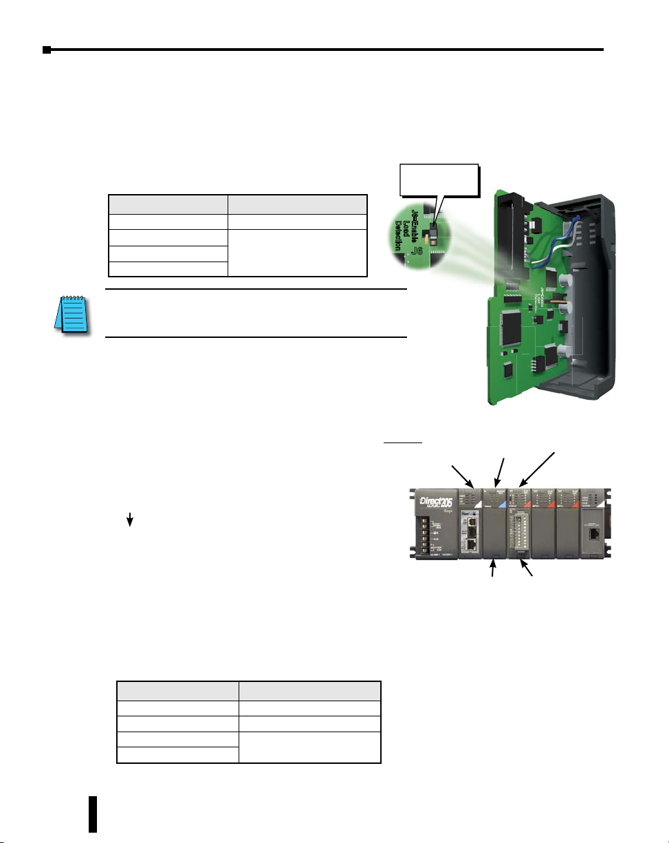
F2–16TD1P, DC Output With Fault Protection, continued
This module detects the following fault statuses and
turns the related X bit(s) on.
1. Missing external 24VDC for the module
2. Open load
3. Over temperature (the output is shut down)
4. Over load current (the output is shut down)
Fault Status X bit Fault Status Indication
Missing external 24VDC All 16 X bits are on.
Open load
Over temperature
Over load current
NOTE: Open load detection can be disabled by removing the
jumper switch J6 on the module PC board. Disable if the load
might be energized by 200µA, or load resistance is > 56kΩ.
Only the X bit assigned to the
faulted output is on
When this module is installed, 16 X bits
are automatically assigned as fault status
indicators. Each X bit indicates the fault
status of a particular output.
In this example, X8-X23 are assigned as fault
status indicators.
X8: Fault status indicator for Y0
X9: Fault status indicator for Y1
X22: Fault status indicator for Y14
X23: Fault status indicator for Y15
Enable Load
Detection
J6=Enable
J6=Enable
Load
Detection
Load
Detection
J6J6
Example
H2-DM1 or H2-DM1E
D2-08ND3
F2-16TD1P
5–18
X0 - X7
The fault status indicators (X bits) will
X8 - X23 Y0
- Y15
automatically reset once the fault condition is
corrected. Over temperature and over load can be
reset by turning the assigned output off or power
cycling the PLC.
Fault Status Operation
Missing external 24VDC Apply external 24VDC
Open load Connect the load.
Over temperature
Over load current
Turn the output (Y bit) off or
power cycle the PLC
Do-more H2 Series PLC Hardware User Manual, 1st Edition, Rev. I - H2-DM-M

Chapter 5: Specifications - Discrete I/O Modules
t
P
12–24VDC
F2–16TD2P, DC Output with Fault Protection
F2-16TD2P DC Output with Fault Protection
Inputs per module
Outputs per module
Commons per module
Output type
Operating voltage
Peak voltage
AC frequency
ON voltage drop
Overcurrent trip
Maximum load current
Maximum OFF current
Base power required 5V
OFF to ON response
ON to OFF response
Terminal type
Status indicators
Weight
Fuses
External DC required
External DC overvoltage
shutdown
oints
16
12
8
4
0
10 20 30 40 50 55°C
0
32 50 68 86 104 122
Ambient Temperature (°C/°F)
24VDC
+–
24V
0V
12–24VDC
+
0V
OUTPUT
L
16 (status indication)
16 (current sourcing)
1
NMOS FET (open source)
10.2–26.4 VDC, external
40VDC
N/A
0.7 V (output current 0.5 A)
0.6 A min., 1.2 A max.
0.25 A continuous, 0.5 A peak
Jumper J6 installed: 200mA; J6
removed: 30mA
70mA
0.5 ms
0.5 ms
Removable (D2-16IOCON)
Logic Side
2.0 oz. (25g)
None
24VDC ±10% @ 50mA
27V, outputs are restored when
voltage is within limits
Reg
O
Derating Char
131°F
OUT
OUT 12-24
A
0
1
A
0
2
1
3
B
2
3
B
F2-1 6TD2P
F2–16TD2P
10.2-26.4
+
L
L
L
L
L
L
L
L
24VDC
L
L
L
L
L
L
L
L
0
1
2
3
24V
+
0
1
2
3
VDC 0.25A
0V
CLASS2
10.2-26.4
VDC 0.25A
CLASS2
4
A
0V
A
0
5
6
7
0V
4
5
6
7
V1
4
0
1
4
1
5
5
2
2
6
6
3
3
7
7
24V
24V
0V
0V
0
0
4
4
1
1
5
5
2
2
6
6
3
3
7
7
B
B
When the A/B switch is in the A position,
the LEDs display the output status of the
module’s first 8 output points. Positon B
displays the output status of the module’s second group of 8 output points.
12-24
VDC
4
VDC
5
4
6
5
7
6
7
Do-more H2 Series PLC Hardware User Manual, 1st Edition, Rev. I - H2-DM-M
5–19
Chapter 5: Specifications - Discrete I/O Modules
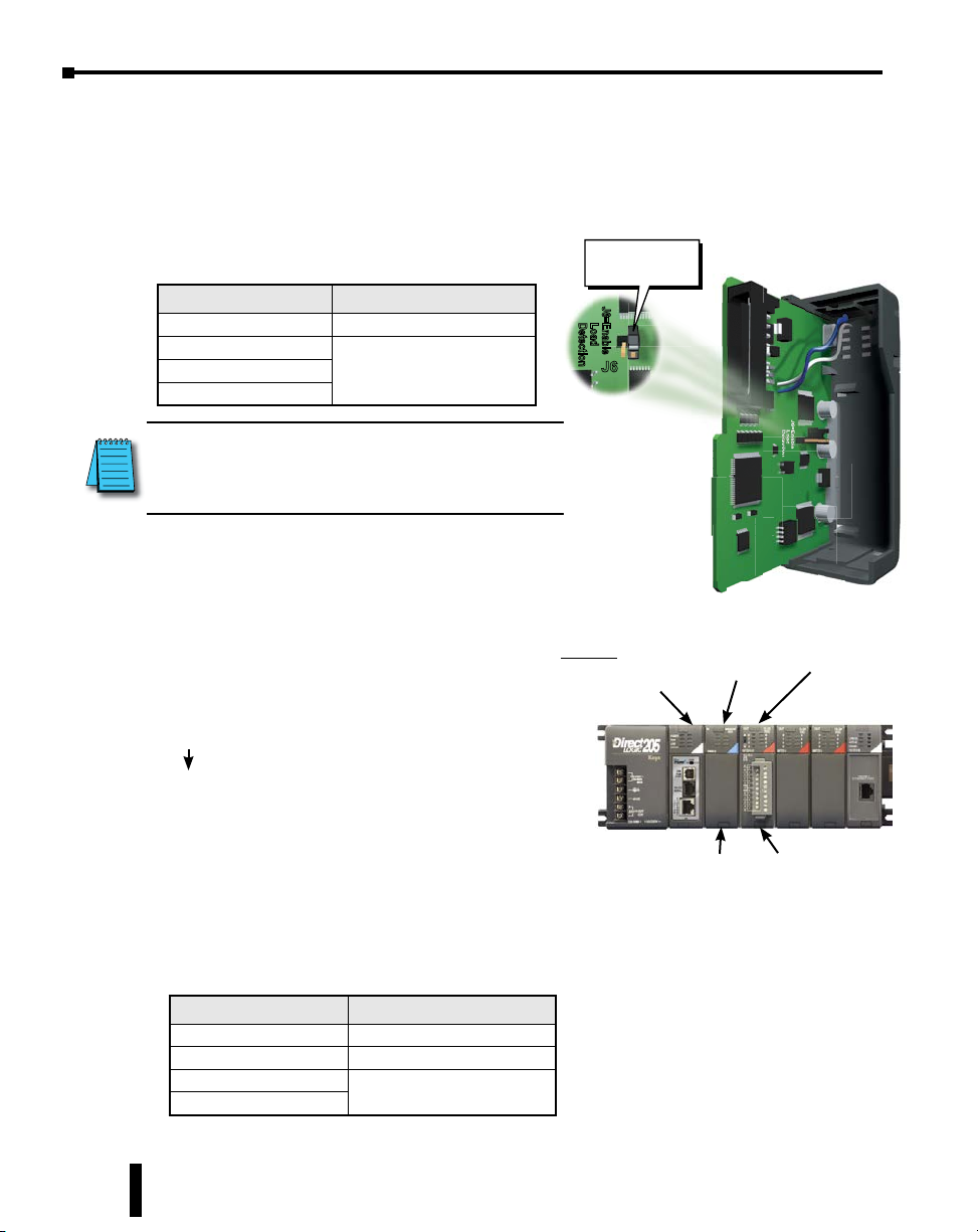
F2–16TD2P, DC Output With Fault Protection, continued
This module detects the following fault statuses and
turns the related X bit(s) on.
1. Missing external 24VDC for the module
2. Open load
3. Over temperature (the output is shut down)
4. Over load current (the output is shut down)
Fault Status X bit Fault Status Indication
Missing external 24VDC All 16 X bits are on.
Open load
Over temperature
Over load current
NOTE: Open load detection can be disabled by removing
the jumper switch J6 on the module PC board. Disable if
the load might be energized by 200µA, or load resistance
is > 56kΩ.
Only the X bit assigned to the
faulted output is on
When this module is installed, 16 X bits
are automatically assigned as fault status
indicators. Each X bit indicates the fault
status of a particular output.
Enable Load
Detection
J6=Enable
J6=Enable
Load
Detection
Load
Detection
J6J6
5–20
In this example, X8-X23 are assigned as fault
status indicators.
Example
H2-DM1 or H2-DM1E
D2-08ND3
X8: Fault status indicator for Y0
X9: Fault status indicator for Y1
X22: Fault status indicator for Y14
X23: Fault status indicator for Y15
The fault status indicators (X bits) will
automatically reset once the fault condition is
X0 - X7
X8 - X23 Y0
- Y15
corrected. Over temperature and over load can be
reset by turning the assigned output off or power
cycling the PLC.
Fault Status Operation
Missing external 24VDC Apply external 24VDC
Open load Connect the load.
Over temperature
Over load current
Turn the output (Y bit) off or
power cycle the PLC
Do-more H2 Series PLC Hardware User Manual, 1st Edition, Rev. I - H2-DM-M
F2-16TD2P
Chapter 5: Specifications - Discrete I/O Modules
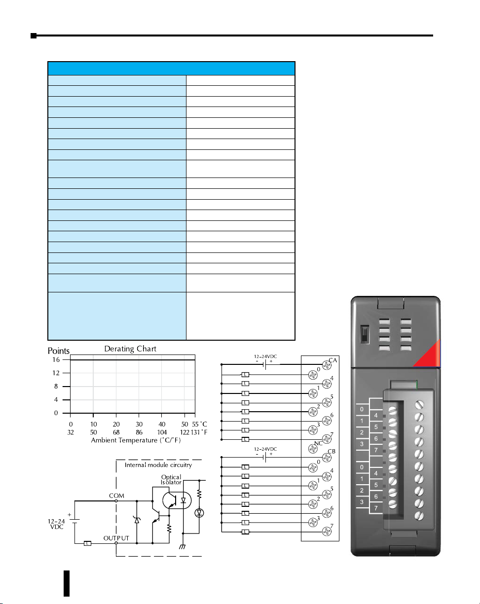
D2–32TD1, DC Output
D2-32TD1 DC Output
Outputs per Module
Commons per Module
Output Type
Operating Voltage
Peak Voltage
ON Voltage Drop
Minimum Load Current
Max Load Current
Max Leakage Current
Max Inrush Current
Base Power Required 5VDC
OFF to ON Response
ON to OFF Response
Terminal Type (not included)
Status Indicator
Weight
Fuses
External DC Power Required
ZIPLink Module
ZIPLink Cable
ZIPLink connector is recommended or purchase custom connector separately.
32 (current sinking)
4 (8 I/O terminal points)
NPN open collector
12–24 VDC
30VDC
0.5 VDC maximum
0.2 mA
0.1 A/point; 3.2 A per module
0.1 mA @ 30VDC
150mA for 10ms
350mA
0.5 ms
0.5 ms
Removable 40-pin connector
Module activity (no I/O status indicators)
2.1 oz. (60g)
None
20–28 VDC max. 120mA (all points on)
ZL-RTB40 (Feedthrough)
ZL-RFU40 (Fuse)
ZL-D24-CBL40 (0.5 m)
ZL-D24-CBL40-1 (1.0 m)
ZL-D24-CBL40-2 (2.0 m)
ZL-D24-CBL40-1P (1.0 m Pigtail)
ZL-D24-CBL40-2P (2.0 m Pigtail)
1
OUT
ACT
D2-32TD1
A0
A4
A1
A5
A2
A6
A3
A7
CI
VI
B0
B4
B1
B5
B2
B6
B3
B7
CII
VII
C0
C4
C1
C5
C2
C6
C3
C7
CIII
VIII
D0
D4
D1
D5
D2
D6
D3
D7
CIV
VIV
12-24VDC
0.1A
CLASS2
12-24
VDC
Do-more H2 Series PLC Hardware User Manual, 1st Edition, Rev. I - H2-DM-M
5–21

Chapter 5: Specifications - Discrete I/O Modules
D2–32TD2, DC Output
D2-32TD2 DC Output
Outputs per Module
Commons per Module
Output Type
Operating Voltage
Peak Voltage
ON Voltage Drop
Minimum Load Current
Max Load Current
Max Leakage Current
Max Inrush Current
Base Power Required 5VDC
OFF to ON Response
ON to OFF Response
Terminal Type (not included)
Status Indicator
Weight
Fuses
ZIPLink Module
ZIPLink Cable
ZIPLink connector is recommended or purchase custom connector separately.
32 (current sourcing)
4 (8 I/O terminal points)
Transistor
12 to 24 VDC
30VDC
0.5 VDC @ 0.1 A
0.2 mA
0.1 A/point; 0.8 A/common
0.1 mA @ 30VDC
150mA @ 10ms
350mA
0.5 ms
0.5 ms
Removable 40-pin connector
Module activity (no I/O status indicators)
2.1 oz (60g)
None
ZL-RTB40 (Feedthrough)
ZL-RFU40 (Fuse)
ZL-D24-CBL40 (0.5 m)
ZL-D24-CBL40-1 (1.0 m)
ZL-D24-CBL40-2 (2.0 m)
ZL-D24-CBL40-1P (1.0 m Pigtail)
ZL-D24-CBL40-2P (2.0 m Pigtail)
1
OUT
ACT
12-24
VDC
D2-32TD2
A0
A4
A1
A5
A2
A6
A3
A7
CI
B0
B4
B1
B5
B2
B6
B3
B7
CII
VII
C0
C4
C1
C5
C2
C6
C3
C7
CIII
VIII
D0
D4
D1
D5
D2
D6
D3
D7
CIV
VIV
12-24VDC
0.1A
CLASS2
VI
5–22
Do-more H2 Series PLC Hardware User Manual, 1st Edition, Rev. I - H2-DM-M

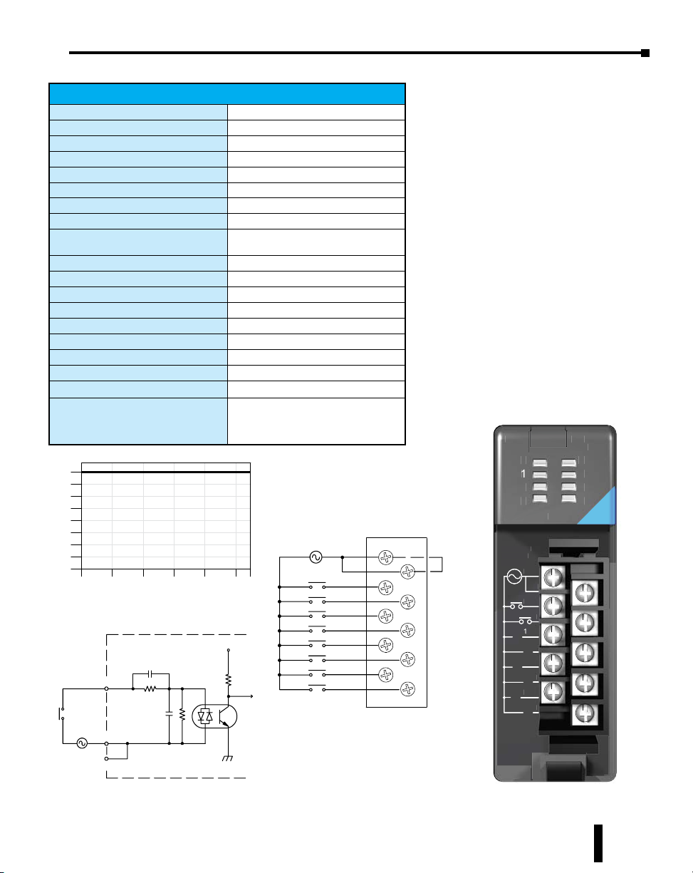
F2–08TA, AC Output
3
C
5A
A
F2-08TA AC Output
Outputs per Module
Commons per Module
Output Type
Operating Voltage
Peak Voltage
ON Voltage Drop
AC Frequency
Minimum Load Current
Max Load Current
Max Leakage Current
Peak One Cycle Surge Current
Base Power Required 5VDC
OFF to ON Response
ON to OFF Response
Terminal Type (included)
Status Indicator
Weight
Fuses
ZIPLink Module
ZIPLink Cable
8
2 (Isolated)
SSR (Triac with zero crossover)
24–140 VAC
140VAC
1.6 V(rms) @ 1.5 A
47 to 63 Hz
50mA
1.5 A / pt @ 30ºC
1.0 A / pt @ 60ºC
4.0 A / common; 8.0 A / module @ 60ºC
0.7 mA(rms)
15A
250mA
0.5 ms - 1/2 cycle
0.5 ms - 1/2 cycle
Removable; D2-8IOCON
Logic side
3.5 oz.
None
ZL-RTB20 (Feedthrough)
ZL-D2-CBL10 (0.5 m)
ZL-D2-CBL10-1 (1.0 m)
ZL-D2-CBL10-2 (2.0 m)
Chapter 5: Specifications - Discrete I/O Modules
20-125
OUT
T
0
1
2
3
F2-08TA
08T
0-125
AC
VAC
4
5
6
7
7
20-125VAC
-125VA
50-60Hz
50-60Hz
.
1.5A
0
1
Do-more H2 Series PLC Hardware User Manual, 1st Edition, Rev. I - H2-DM-M
C0-3
3
5
6
1
-
2
4
C4-7
7
4-7
5–23

Chapter 5: Specifications - Discrete I/O Modules
C
A
z
A
220
D2–08TA, AC Output
D2-08TA AC Output
Outputs per Module
Commons per Module
Output Type
Operating Voltage
Peak Voltage
ON Voltage Drop
AC Frequency
Minimum Load Current
Max Load Current
Max Leakage Current
Max Inrush Current
Base Power Required 5VDC
OFF to ON Response
ON to OFF Response
Terminal Type (included)
Status Indicator
Weight
Fuses
ZIPLink Module
ZIPLink Cable
8
1 (2 I/O terminal points)
SSR (Triac)
15–264 VAC
264VAC
< 1.5 VAC (>0.1 A)
< 3.0 VAC (<0.1 A)
47 to 63 Hz
10mA
0.5 A/point; 4A/common
4mA (264VAC, 60Hz)
1.2 mA (100VAC, 60Hz)
0.9 mA (100VAC, 50Hz)
10A for 10ms
250mA
1ms
1ms + 1/2 cycle
Removable; D2-8IOCON
Logic side
2.8 oz. (80g)
1 per common, 6.3 A slow blow,
non-replaceable
ZL-RTB20 (Feedthrough)
ZL-D2-CBL10 (0.5 m)
ZL-D2-CBL10-1 (1.0 m)
ZL-D2-CBL10-2 (2.0 m)
OUT110-220
OUT
0
1
2
3
D2-08TA
2-08T
AC
VAC
-
4
5
6
7
5–24
15-264VAC
-264VA
mA-0.5
10mA-0.5A
H
50/60Hz
C
C
C
0
L
4
L
1
5
2
6
3
7
Do-more H2 Series PLC Hardware User Manual, 1st Edition, Rev. I - H2-DM-M

D2–12TA, AC Output
15-- 132VAC
AddressesUsed
Po
.
D2-12TA AC Output
Outputs per Module
Outputs Points Consumed
Commons per Module
Output Type
Operating Voltage
Peak Voltage
ON Voltage Drop
AC Frequency
Minimum Load Current
Max Load Current
Max Leakage Current
Max Inrush Current
Base Power Required 5VDC
OFF to ON Response
ON to OFF Response
Terminal Type (included)
Status Indicator
Weight
Fuses
ZIPLink Module
ZIPLink Cable
Derating Chart
300mA/Pt.
AmbientTempera ture (°C/°F)
12
9
6
3
0
ints
0102030405055
32 50 68 86 104 122 131C°F°
12
16 (four unused, see chart right)
2 (isolated)
SSR (Triac)
15–132 VAC
132VAC
< 1.5 VAC (>50mA)
< 4.0 VAC (<50mA)
47 to 63 Hz
10mA
0.3 A /point; 1.8 A/common
2mA (132VAC, 60Hz)
10A for 10ms
350mA
1ms
1ms + 1/2 cycle
Removable; D2-16IOCON
Logic side
2.8 oz. (80g)
(2) 1 per common
3.15 A slow blow, replaceable
Order D2-FUSE-1 (5 per pack)
ZL-RTB20 (Feedthrough)
ZL-RFU20 (Fuse)
ZL-D2-CBL19 (0.5 m)
ZL-D2-CBL19-1 (1.0 m)
ZL-D2-CBL19-2 (2.0 m)
ZL-D2-CBL19-1P (1.0 m Pigtail)
ZL-D2-CBL19-2P (2.0 m Pigtail)
250mA/Pt
L
Chapter 5: Specifications - Discrete I/O Modules
OUTPUT
Yn+0
Yn+1
Yn+2
Yn+3
Yn+4
Yn+5 Yes
Yn+7 No
Y
nisthe starting address
L
L
L
L
L
L
15-- 132VAC
L
L
L
L
L
L
Internal module circuitry
Points
Optical
Isolator
Us ed?
Yes
Yes
Yes
Yes
Yes
NoYn+6
0
1
2
3
0
1
2
3
NC
To LE D
CA
4
5
NC
NC
CB
4
5
NC
NC
Points
Yn+
Yn+
Yn+10
Yn+11
Yn+12
Yn+13
Yn+14
Yn+15
Us ed?
Yes
8
9
Yes
Yes
Yes
Yes
Yes
OUT
0
A
1
2
B
3
D2-12TA
15-132VAC
10mA-0.3A
50/60Hz
CA
CB
No
No
18-110
VAC
4
5
COM
15-- 132
VAC
3.15A
Do-more H2 Series PLC Hardware User Manual, 1st Edition, Rev. I - H2-DM-M
5–25

Chapter 5: Specifications - Discrete I/O Modules
5-
TR
C
z
C
2A
S
T
C
Po
/
/
/
Dera ting Chart
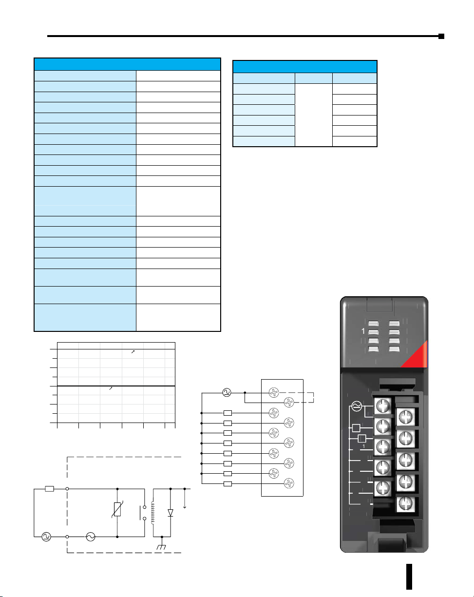
D2–04TRS, Relay Output
Outputs per Module
Outputs Points Consumed
Commons per Module
Output Type
Operating Voltage
Peak Voltage
ON Voltage Drop
AC Frequency
Minimum Load Current
Max Load Current (resistive)
Max Leakage Current
Max Inrush Current
Base Power Required 5VDC
OFF to ON Response
ON to OFF Response
Terminal Type (included)
Status Indicator
Weight
Fuses
ZIPLink Module*
ZIPLink Cable*
*D2-04TRS outputs are derated not to exceed 2 Amps per point
and 2 Amps per common when using the ZIPLink wiring system.
ints
4
3
2
1
0
0
32
D2-04TRS Relay Output
4
8 (only 1st 4pts are used)
4 (isolated)
Relay, form A (SPST)
5–30 VDC / 5–240 VAC
30 VDC, 264 VAC
0.72 VDC maximum
47 to 63 Hz
10mA
4A/point; 8A/module (resistive)
0.1 mA @ 264VAC
5A for < 10ms
250 mA
10ms
10ms
Removable; D2-8IOCON
Logic side
2.8 oz. (80g)
1 per point
6.3 A slow blow, replaceable
Order D2-FUSE-3 (5 per pack)
ZL-RTB20 (Feedthrough)
ZL-D2-CBL10 (0.5 m)
ZL-D2-CBL10-1 (1.0 m)
ZL-D2-CBL10-2 (2.0 m)
10 20 30 40 50 55
50 68 86 104122 131C°F°
AmbientTemperature (°C/°F)
2A
Pt.
3A
Pt.
4A
Pt.
L
5--30VDC
-240 VAC
OUTPUT
COM
Typical Relay Life (Operations)
Voltage & Load Current
Type of Load 1A 2A 3A 4A
24VDC Resistive 500k 200k 100k 50k
24VDC Solenoid
110VAC Resistive 500k 250k 150k 100k
110VAC Solenoid
220VAC Resistive 350k 150k 100k 50k
220VAC Solenoid
1. At 24VDC solenoid (inductive) loads over 2A cannot be used.
2. At 100VAC solenoid (inductive) loads over 3A cannot be used.
3. At 220VAC solenoid (inductive) loads over 2A cannot be used.
5--30VDC
5--240 VAC
Internal module circuitry
6.3A
1
100k 40k – –
2
200k 100k 50k
3
100k 50k – –
NC
NC
OU
OU
C0
L
L
L
L
0
C1
1
C2
2
C3
3
To LED
0
1
2
3
D2-04TRS
2-04TR
5-240VAC
-240VA
A 50/60H
2A 50/60Hz
-30VD
5-30VDC
NC
NC
N
C0
0
L
C1
1
1
L
C2
2
L
C3
3
3
L
mA-
10mA-2A
ELAY
5–26
Do-more H2 Series PLC Hardware User Manual, 1st Edition, Rev. I - H2-DM-M
D2–08TR, Relay Output
ed
AmbientTemperature (°C/°F)
Dera ting Chart
TR
C
z
R
C
A
5--240 VAC
D2-08TR Relay Output
Outputs per Module
Outputs Points Consumed
Commons per Module
Output Type
Operating Voltage
Peak Voltage
ON Voltage Drop
AC Frequency
Minimum Load Current
Max Load Current (resistive)
Max Leakage Current
Max Inrush Current
Base Power Required 5VDC
OFF to ON Response
ON to OFF Response
Terminal Type (included)
Status Indicator
Weight
Fuses
ZIPLink Module
ZIPLink Cable
Points
8
6
4
2
0
0102030405055
32 50 68 86 104122 131C°F°
Internal module circuitry
OUTPUT
L
COM
5--30VDC
6.3A
1A /Pt.
8
8
1 (2 I/O terminals)
Relay, form A (SPST)
5–30 VDC; 5–240 VAC
30VDC, 264VAC
N/A
47 to 60 Hz
5mA @ 5VDC
1A/point; 4A/common
0.1 mA @265VAC
Output: 3A for 10ms
Common: 10A for 10ms
250mA
12ms
10ms
Removable; D2-8IOCON
Logic side
3.9 oz. (110g)
One 6.3 A slow blow, replaceable
Order D2-FUSE-3 (5 per pack)
ZL-RTB20 (Feedthrough)
ZL-D2-CBL10 (0.5 m)
ZL-D2-CBL10-1 (1.0 m)
ZL-D2-CBL10-2 (2.0 m)
0.5A /Pt.
To LED
Chapter 5: Specifications - Discrete I/O Modules
Typical Relay Life (Operations)
Voltage/Load Current Closures
24VDC Resistive
24VDC Solenoid 100k
110VAC Resistive 500k
110VAC Solenoid 200k
1A
220VAC Resistive 350k
220VAC Solenoid 100k
5--30VDC
5--240 VAC
L
L
L
L
L
L
L
L
C
0
1
2
3
Internally
connect
C
4
5
6
7
500k
OU
OUT
0
1
2
3
D2-08TR
2-08T
5-240VAC
-240VA
A 50/60H
1A 50/60Hz
C
0
L
L
1
2
3
5-30VDC
-30VD
mA-1
5mA-1A
ELAY
4
5
6
7
C
4
4
5
6
7
Do-more H2 Series PLC Hardware User Manual, 1st Edition, Rev. I - H2-DM-M
5–27

Chapter 5: Specifications - Discrete I/O Modules
TR
O1
O2
O4
O7
0
3
z
C
10A
12
(1
A/pt.
F2–08TR, Relay Output
F2-08TR Relay Output
Outputs per Module
Outputs Points Consumed
Commons per Module
Output Type
Operating Voltage
Peak Voltage
ON Voltage Drop
AC Frequency
Minimum Load Current
Max Load Current (resistive)
Max Leakage Current
Max Inrush Current
Base Power Required 5VDC
OFF to ON Response
ON to OFF Response
Terminal Type (included)
Status Indicator
Weight
Fuses
ZIPLink Module*
ZIPLink Cable*
*F2-08TR outputs are derated not to exceed 2 Amps per point and
4 Amps per common when using the ZIPLink wiring system.
8
6
Number
00%duty
cycle)
12-- 28VDC
-- 250VAC
4
2
0
0102030405055
32 50 68 86 104122 131C°F°
AmbientTempera ture (°C/°F)
Internal Circuit ry
Common
Points On
8
8
2 (isolated), 4-pts per common
8, Form A (SPST normally open)
7A @ 12–28 VDC, 12–250 VAC;
0.5 A @ 120VDC
150VDC, 265VAC
N/A
47 to 63 Hz
10mA @ 12VDC
10A/point 3 (Subject to derating)
Max of 10A/common
N/A
12A
670mA
15ms (typical)
5ms (typical)
Removable; D2-8IOCON
Logic side
5.5 oz. (156g)
None
ZL-RTB20 (Feedthrough)
ZL-D2-CBL10 (0.5 m)
ZL-D2-CBL10-1 (1.0 m)
ZL-D2-CBL10-2 (2.0 m)
Dera ting Chart
2.5
3 A/pt.
5A/pt.
10 A/pt.
Typical Circuit
Typical Relay Life1 (Operations)
at Room Temperature
Voltage &
Type of Load
2
24VDC Resistive 10M 600k 300k
24VDC Solenoid – 150k 75k
110VDC Resistive – 600k 300k
110VDC Solenoid – 500k 200k
220VAC Resistive – 300k 150k
220VAC Solenoid – 250k 100k
1. Contact life may be extended beyond those values shown with the
use of arc suppression techniques described in the DL205 User Manual.
Since these modules have no leakage current, they do not have built-in
snubber. For example, if you place a diode across a 24VDC inductive
load, you can significantly increase the life of the relay
2. At 120VDC 0.5 A resistive load, contact life cycle is 200k cycles.
3. Normally closed contacts have 1/2 the current handling
capability of the normally open contacts.
L
L
L
L
L
L
L
L
Load Current
50mA 5A 7A
OU
UT
0
1
2
3
F2-08TR
F2-08TR
12-250VAC
12-250VA
10A 50/60Hz
10A 50/60H
12-28VDC
12-28VD
mA-
10mA-10A
NO0
O
NO1
N
CO-3
-
N
NO2
NO3
N
NO4
NO5
C4-7
4-7
NO6
NO7
N
ELAY
4
5
6
7
5–28
NO
L
Do-more H2 Series PLC Hardware User Manual, 1st Edition, Rev. I - H2-DM-M

F2–08TRS, Relay Output
Typical Circuit
/
/
(1
12
TR
Outputs per Module
Outputs Points Consumed
Commons per Module
Output Type
Operating Voltage
Peak Voltage
ON Voltage Drop
AC Frequency
Minimum Load Current
Max Load Current (resistive)
Max Leakage Current
Max Inrush Current
Base Power Required 5VDC
OFF to ON Response
ON to OFF Response
Terminal Type (included)
Status Indicator
Weight
Fuses
ZIPLink Module*
ZIPLink Cable*
*F2-08TRS outputs are derated not to exceed 2 Amps per point
and 2 Amps per common when using the ZIPLink wiring system.
Number
Poin ts On
00%duty
cycle)
12-- 28VDC
-- 250VAC
L
F2-08TRS Relay Output
8
8
8 (isolated)
3, Form C (SPDT)
5, Form A (SPST normally open)
7A @ 12–28 VDC, 12–250 VAC
0.5 A @ 120VDC
150VDC, 265VAC
N/A
47 to 63Hz
10mA @ 12VDC
7A/point 3 (subject to derating)
N/A
12A
670mA
15ms (typical)
5ms (typical)
Removable; D2-16IOCON
Logic side
5.5 oz. (156g)
None
ZL-RTB20 (Feedthrough)
ZL-D2-CBL19 (0.5 m)
ZL-D2-CBL19-1 (1.0 m)
ZL-D2-CBL19-2 (2.0 m)
ZL-D2-CBL19-1P (1.0 m Pigtail)
ZL-D2-CBL19-2P (2.0 m Pigtail)
Dera ting Chart
8
6
4
2
0
0102030405055
32 50 68 86 104122131C°F°
AmbientTempera ture (°C/°F )
Typical Circuit
(points1,2,3,4,5)
Internal Circuitry
Common
NO
5A/pt.
7A/pt.
4A
pt.
6A
pt.
12-- 28VDC
12-- 250VA C
L
L
Chapter 5: Specifications - Discrete I/O Modules
Typical Relay Life1 (Operations)
at Room Temperature
Load Current
50mA 5A 7A
L
OU
0
L
1
2
3
L
L
L
L
F2-08TRS
12-250VAC
7A 50/60Hz
12-28VDC
10mA-7A
NO0
C1
C0
NO1
NC0
C2
C3
NO2
NO3
C4
C5
NO4
NO5
NC6
NC7
C6
C7
NO6
NO7
ELAY
4
5
6
7
Common
NO
NC
Voltage &
Type of Load
2
24VDC Resistive 10M 600k 300k
24VDC Solenoid – 150k 75k
110VDC Resistive – 600k 300k
110VDC Solenoid – 500k 200k
220VAC Resistive – 300k 150k
220VAC Solenoid – 250k 100k
1. Contact life may be extended beyond those values shown with the
use of arc suppression techniques described in the DL205 User Manual.
Since these modules have no leakage current, they do not have built-in
snubber. For example, if you place a diode across a 24VDC inductive
load, you can significantly increase the life of the relay
2. At 120VDC 0.5 A resistive load, contact life cycle is 200k cycles.
3. Normally closed contacts have 1/2 the current handling
capability of the normally open contacts.
12-- 28VDC
12-- 250VAC
L
12-- 28VDC
12-- 250VAC
L
12-- 28VDC
12-- 250VAC
L
normally closed
L
12-- 28VDC
12-- 250VAC
L
(Points0,6,&7 only)
Internal Circuitry
C1
NO 1
C2
NO 2
C4
NO 4
NC 6
C6
NO 6
NO 0
C0
NC 0
C3
NO 3
C5
NO 5
NC 7
C7
NO 7
12-- 28VDC
12-- 250VAC
normally closed
12-- 28VDC
12-- 250VAC
12-- 28VDC
12-- 250VAC
normally closed
12-- 28VDC
12-- 250VAC
Do-more H2 Series PLC Hardware User Manual, 1st Edition, Rev. I - H2-DM-M
5–29

Chapter 5: Specifications - Discrete I/O Modules
Po
C
F
TR
D
5-
D2–12TR, Relay Output
Outputs per Module
Outputs Points Consumed
Commons per Module
Output Type
Operating Voltage
Peak Voltage
ON Voltage Drop
AC Frequency
Minimum Load Current
Max Load Current (resistive)
Max Leakage Current
Max Inrush Current
Base Power Required 5VDC
OFF to ON Response
ON to OFF Response
Terminal Type (included)
Status Indicator
Weight
Fuses
ZIPLink Module
ZIPLink Cable
5–30
D2-12TR Relay Output
12
16 (four unused, see chart below)
2 (6-pts. per common)
Relay, form A (SPST)
5–30 VDC; 5–240 VAC
30VDC; 264VAC
N/A
Typical Relay Life (Operations)
Voltage/Load Current Closures
24VDC Resistive
24VDC Solenoid 100k
110VAC Resistive 500k
110VAC Solenoid 200k
1A
220VAC Resistive 350k
220VAC Solenoid 100k
500k
47 to 60 Hz
5mA @ 5VDC
1.5 A/point; Max of 3A/common
0.1 mA @ 265VAC
Output: 3A for 10ms
Common: 10A for 10ms
450mA
10ms
10ms
Removable; D2-16IOCON
Logic side
4.6 oz. (130g)
(2) 4A slow blow, replaceable
Points Used? Points Used?
Yn+0 Yes Yn+8 Yes
Yn+1 Yes Yn+9 Yes
Yn+2 Yes Yn+10 Yes
Yn+3 Yes Yn+11 Yes
Yn+4 Yes Yn+12 Yes
Yn+5 Yes Yn+13 Yes
Yn+6 No Yn+14 No
Yn+7 No Yn+15 No
Addresses Used
Yn is the starting address
Order D2-FUSE-4 (5 per pack)
ZL-RTB20 (Feedthrough)
ZL-RFU20 (Fuse)
ZL-D2-CBL19 (0.5 m)
OU
A
ZL-D2-CBL19-1 (1.0 m)
ZL-D2-CBL19-2 (2.0 m)
ZL-D2-CBL19-1P (1.0 m Pigtail)
ZL-D2-CBL19-2P (2.0 m Pigtail)
ints
12
8
Dera ting Chart
0.5A /Pt.
0.75A/Pt.
4
0
1.5A /Pt.
0102030405055
32 50 68 86 104122 131
AmbientTemperature (°C/°F)
Internal module circuitry
OUTPUT
L
COM
5--30VDC
-240 VAC
4A
1.25A/Pt.
To LE
5--30VDC
5--240 VA C
L
L
L
L
L
L
°
°
5--30VDC
5--240 VA C
L
L
L
L
L
L
CA
0
4
1
5
2
NC
3
NC
NC
CB
0
4
1
5
2
NC
3
NC
B
D2-12TR
5-240VAC
1.5A 50/60Hz
5-30VDC
5mA-1.5A
Do-more H2 Series PLC Hardware User Manual, 1st Edition, Rev. I - H2-DM-M
0
1
2
3
CA
CB
ELAY
4
5

Chapter 5: Specifications - Discrete I/O Modules
Derating Chart
AmbientTempera ture (°C/°F)
5--240 VAC
24VDC
D
5-
24VDC
D
Sour
08C
/
T
/
A
C
C
C
A
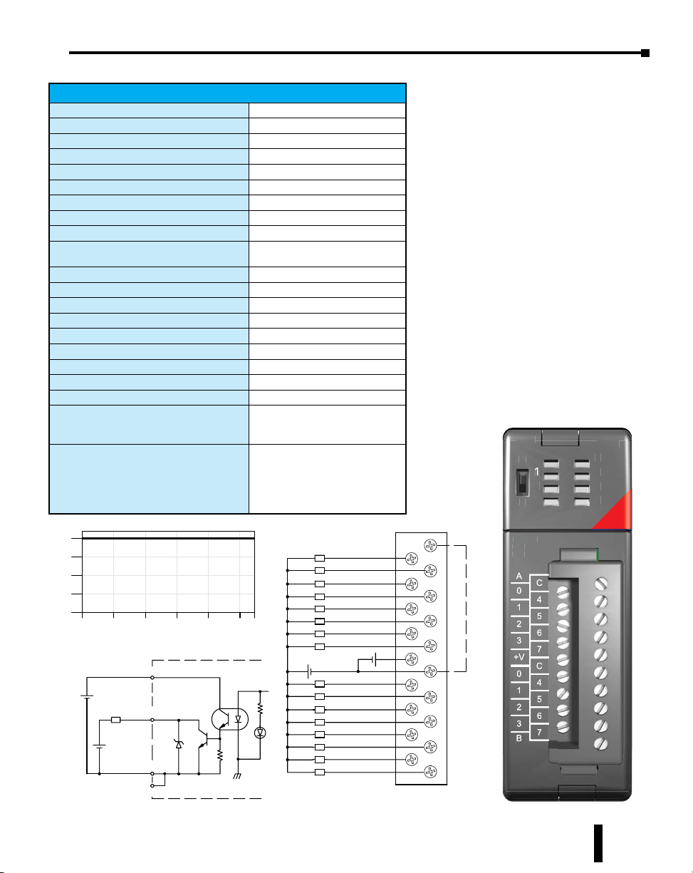
D2–08CDR, 4 pt. DC Input / 4pt. Relay Output
D2-08CDR 4-pt. DC In / 4pt. Relay Out
General Specifications
Base Power Required 5VDC
Terminal Type (included)
Status Indicator
Weight
Input Specifications
Inputs per Module
Input Points Consumed
Commons per Module
Input Voltage Range
Peak Voltage
ON Voltage Level
OFF Voltage Level
AC Frequency
Input Impedance
Input Current
Maximum Current
Minimum ON Current
Maximum OFF Current
OFF to ON Response
ON to OFF Response
Fuses (input circuits)
Output Specifications
Outputs per Module
Outputs Points Consumed
Commons per Module
Points
4
3
2
1
0
0102030405055
32 50 68 86 104 122131C°F°
Sink
ce
+
Internal module circuitry
INPUT
COM
200mA
Removable; D2-8IOCON
Logic side
3.5 oz. (100g)
4 (sink/source)
8 (only first 4-pts are used)
1
20–28 VDC
30VDC
19VDC minimum
7VDC maximum
N/A
4.7 kq
5mA @ 24VDC
8mA @ 30VDC
4.5 mA
1.5 mA
1 to 10 ms
1 to 10 ms
None
4
8 (only first 4-pts are used)
1
Outputs
1A /Pt.
Inputs
5mA/
Pt.
V+
To LE
Optical
Isolator
5--30VDC
Output Type
Operating Voltage
Peak Voltage
ON Voltage Drop
AC Frequency
Minimum Load Current
Max Load Current (resistive)
Max Leakage Current
Max Inrush Current
OFF to ON Response
ON to OFF Response
Fuses (output circuits)
ZIPLink Module
ZIPLink Cable
Typical Relay Life (Operations)
Voltage/Load Current Closures
24VDC Resistive
24VDC Solenoid 100k
110VAC Resistive 500k
110VAC Solenoid 200k
220VAC Resistive 350k
220VAC Solenoid 100k
Source
Sink
+--
Internal module circuitry
OUTPUT
L
COM
-240 VAC
6.3A
1A
L
L
L
L
5--30VDC
Relay, form A (SPST)
5–30 VDC; 5–240 VAC
30VDC; 264VAC
N/A
47 to 63 Hz
5mA @ 5VDC
1A/point ; 4A/module
0.1 mA @ 264VAC
3A for < 100 ms, 10A for < 10ms (common)
12ms
10ms
1 (6.3 A slow blow, replaceable);
Order D2-FUSE-3 (5 per pack)
ZL-RTB20 (Feedthrough)
ZL-D2-CBL10 (0.5 m)
ZL-D2-CBL10-1 (1.0 m)
ZL-D2-CBL10-2 (2.0 m)
500k
IN/
N
OUT
U
A
CA
O
0
1
1
2
2
3
3
CB
To LE
0
1
2
3
D2-08CDR
D2-
20-28VDC
-28VD
8mA
8mA
CA
L
0
L
1
1
L
2
L
3
CB
-240VA
5-240VAC
A 50/60Hz
1A 50/60Hz
-30VD
5-30VDC
mA-1
5mA-1A
DR
0
1
2
3
24VDC/
4VDC
RELAY
0
1
2
3
B
Do-more H2 Series PLC Hardware User Manual, 1st Edition, Rev. I - H2-DM-M
5–31
 Loading...