

Page 1
domnick hunter
dh
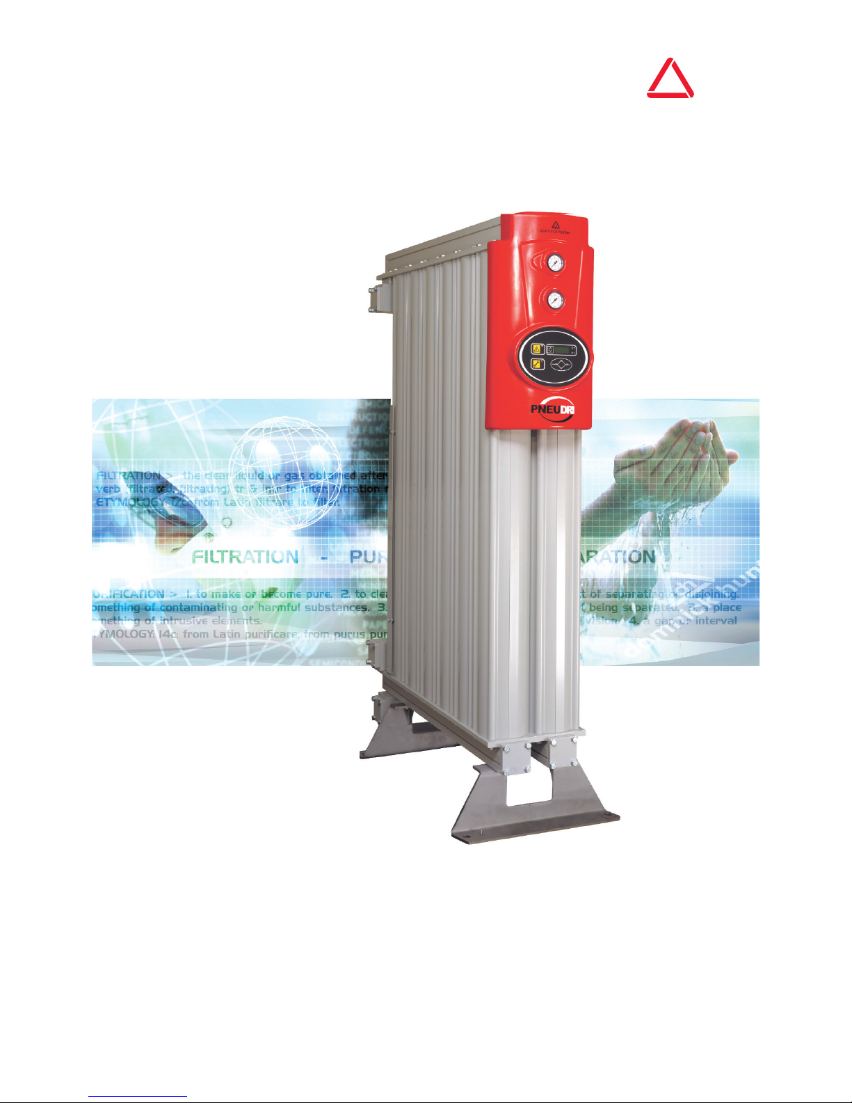
PNEUDRI MAXI
MX102 – MX110
USER GUIDE
• GEBRUIKERSHANDLEIDING • ANWENDERHANDBUCH • GUIDE D’UTILISATION
• KÄYTTÖOPAS • BRUKSANVISNING • BRUKERVEILEDNING • BRUGERVEJLEDNING
• ΕΓΧΕΙΡΙ∆ΙΟ ΧΡΗΣΗΣ • GUÍA DEL USUARIO • GUIA DO UTILIZADOR • MANUALE UTENTE
• INSTRUKCJA UŻYTKOWNIKA • POUŽÍVATEĽSKÁ PRÍRUČKA • UŽIVATELSKÁ PŘÍRUČKA
• KASUTUSJUHEND • HASZNÁLATI ÚTMUTATÓ • LIETOTĀJA ROKASGRĀMATA
• VARTOTOJO VADOVAS • РУКОВОДСТВО ПОЛЬЗОВАТЕЛЯ • NAVODILA ZA UPORABO
• KULLANIM KILAVUZU •
GWIDA G{ALL-UTENT
Page 2

Page 3

3
Contents
1. Safety Information 4
1.1 Markings and symbols 5
1.2 Hazardous Substances 5
2. Description 6
2.1 Technical Specification 7
2.1.1 Dimensions 7
2.2 Unpacking the equipment 8
2.3 Overview of the equipment 8
3. Installation & Commissioning 9
3.1 Recommended system layout 9
3.2 Locating the equipment 9
3.3 Mechanical Installation 9
3.4 Electrical Installation 10
3.4.1 Remote alarm indication 10
3.4.2 MXS–DS Hygrometer connection. 10
3.4.3 MXA Analogue Outputs 10
4. Operating the equipment 11
4.1 Overview of Controls 11
4.2 Starting the equipment 11
4.3 Stopping the equipment 11
5. Servicing 12
5.1 Cleaning 12
5.2 Service Intervals 12
5.3 Service Kits 13
5.4 Service Record 13
6. Troubleshooting guide 14
Declaration of Conformity 285
Page 4

4
MX 102 - MX110 User Guide
1. Safety Information
Important: Do not operate this equipment until the safety information and instructions in this user guide have been read and
understood by all personnel concerned.
Only competent personnel trained, qualified, and approved by domnick hunter should perform commissioning, service and
repair procedures.
Use of the equipment in a manner not specified within this user guide may impair safety and invalidate your warranty.
When handling, installing or operating this equipment, personnel must employ safe engineering practices and observe all related
regulations, health & safety procedures, and legal requirements for safety.
Ensure that the equipment is depressurised and electrically isolated, prior to carrying out any of the scheduled maintenance
instructions specified within this user guide.
Most accidents that occur during the operation and maintenance of machinery are the result of failure to observe basic safety rules
and procedures. Accidents can be avoided by recognising that any machinery is potentially hazardous.
domnick hunter can not anticipate every possible circumstance which may represent a potential hazard. The warnings in this
manual cover the most known potential hazards, but by definition can not be all-inclusive. If the user employs an operating
procedure, item of equipment or a method of working which is not specifically recommended by domnick hunter the user must
ensure that the equipment will not be damaged or become hazardous to persons or property.
Should you require an extended warranty, tailored service contracts or training on this equipment, or any other equipment within the
domnick hunter range, please contact your local domnick hunter office.
Details of your nearest domnick hunter sales office can be found at: www.domnickhunter.com.
Page 5
1.2 Hazardous Substances
The chambers of the dryer are filled with DRYFIL desiccant material. This is a powerful desiccant and will dry out the
atmosphere, eyes, nose, and mouth.
If the desiccant comes into contact with the eyes or skin, wash the affected area with copious amounts of water.
DRYFIL may contain some dust therefore an orinasal dust respirator should be worn when handling the equipment. Adequate
ventilation should be provided when working with desiccant.
The desiccant is classified as non-hazardous for transportation.
DRYFIL will evolve heat on contact with moisture and may generate pressure in a confined space. DRYFIL should therefore be
stored in a dry place in its original packaging.
DRYFIL is non-flammable. Any fire should be fought by means appropriate to the material causing the fire.
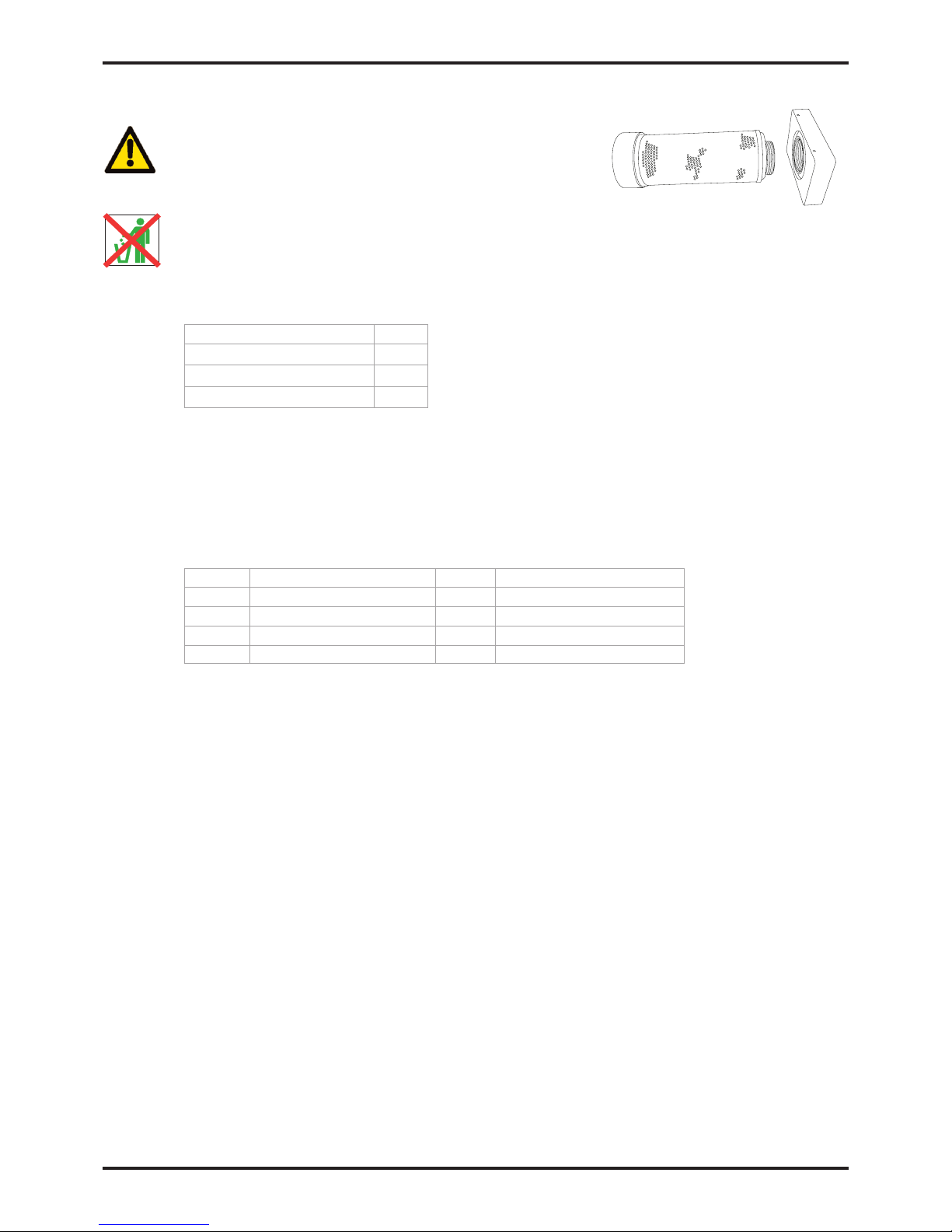
DRYFIL should be disposed of into a licensed land fill site.
5
MX 102 - MX110 User Guide
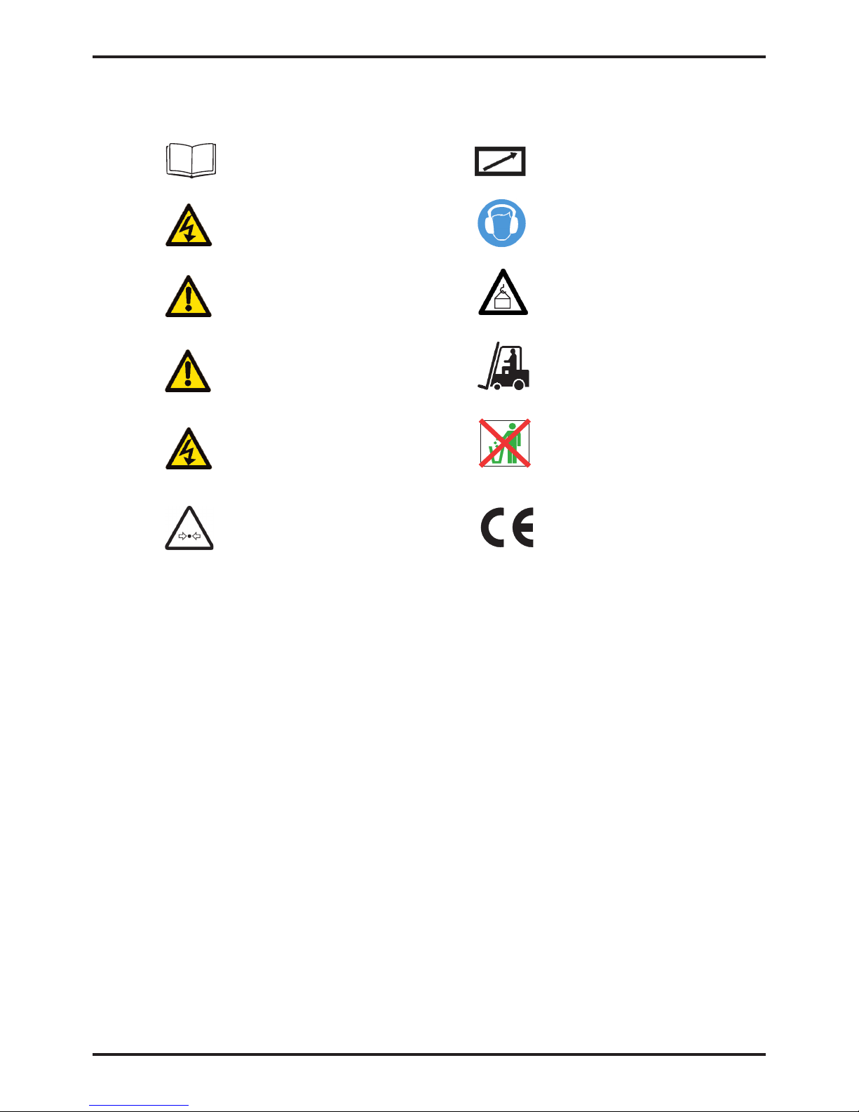
Caution, Read the User Guide.
Risk of electric shock.
Highlights actions or procedures which, if not
performed correctly, may lead to personal
injury or death.
Highlights actions or procedures which, if not
performed correctly, may lead to damage to
this equipment.
Highlights actions or procedures which, if not
performed correctly, could lead to electric
shock.
Pressurised components on system
May start automatically without warning
Wear ear protection.
Use lifting equipment
Use a forklift truck
When disposing of old parts always follow local
waste disposal regulations
Conformité Européenne
Warning
Warning
Caution
1.1 Markings and symbols
The following markings and international symbols are used on the equipment and within this user guide:
Page 6

6
MX 102 - MX110 User Guide
2. Description
domnick hunter desiccant dryers are designed to remove moisture vapour from compressed air. Providing pressure dewpoints
of -20°C (-4°F), -40°C (-40°F) or -70°C (-100°F) at specified conditions.
ISO 8573.1 Air Quality Class
-20°C (-4°F) PDP 1.3.1.*
-40°C (-40°F) PDP 1.2.1.*
-70°C (-100°F) PDP 1.1.1.*
*(when fitted with suitable downstream filtration)
The dryers comprise of extruded aluminium columns. Each column contains twin chambers filled with desiccant material that dries
the compressed air as it passes through. One chamber is operational (drying), whilst the opposite chamber is regenerating by
Pressure Swing Adsorption (PSA).
Pressure Swing Adsorption (PSA)
A small amount of the dried compressed air is used to regenerate the spent desiccant bed. Dried air at line pressure is expanded to
atmospheric pressure through the regenerating column.
Patented Modular Construction
The unique, patented modular construction of PNEUDRI enables the dryers to be sized to exact flow requirements. By simply adding
further modules (banks) of PNEUDRI, the operational capacity of the dryer can be increased to precisely match any system
demands.
Page 7
7
MX 102 - MX110 User Guide
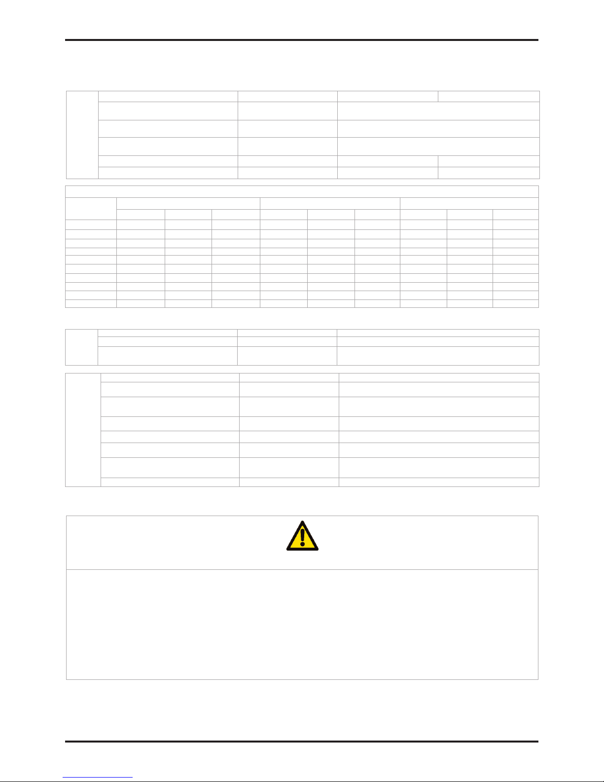
Parameter Units MX102 – MX104 MX105 – MX110
Minimum Inlet Pressure
bar g
(psi g / MPa g)
4
(58 / 0.4)
Maximum Inlet Pressure
bar g
(psi g / MPa g)
13
(190 / 1.3)
Inlet Temperature
ºC
(ºF)
2 – 50
35 - 122
Inlet Connection Inches 2” 2 1/2”
Outlet Connection Inches 2” 2 1/2”
Specific
Stated flows are for operation at 7 bar g (102 psi g / 0.7 MPag) with reference to 20ºC, 1 bar (a), 0% relative water vapour pressure.
Flowrate (7 barg / 100 psi g / 0.7 MPa g @ 35ºC / 95ºF)
Model
Dewpoint -40ºC (-40ºF)
Dewpoint -70ºC (-100ºF) Dewpoint -20ºC (-4ºF)
cfm m3/ min m3/ hour cfm m3/ min m3/ hour cfm m3/ min m3/ hour
MX102c 240 6.80 408 168 4.76 285 264 7.48 449
MX103c 360 10.19 611 252 7.14 428 396 11.21 673
MX103 450 12.75 765 315 8.92 535 495 14.02 841
MX104 600 17.00 1020 420 11.89 713 660 18.69 1121
MX105 750 21.25 1275 525 14.87 892 825 23.36 1402
MX106 900 25.50 1530 630 17.84 1070 990 28.03 1682
MX107 1050 29.75 1785 735 20.82 1248 1155 32.70 1962
MX108 1200 34.00 2040 840 23.79 1427 1320 37.38 2243
MX109
- - -
945 26.76 1605
- - -
MX110
- - -
1050 29.73 1783
- - -
Parameter Units MX102 – MX110
Supply Voltage V ac 100 - 240V ac 50/60Hz ± 10%
Power W
MXS = 18W Max
MXA = 35W Max
Electrical
Parameter Units MX102 – MX110
Temperature
ºC
(ºF)
2 - 45
35 - 113
Humidity -
50% @ 40ºC
(80% MAX ≤ 31ºC)
IP Rating
-
IP65 / >NEMA 13
Pollution Degree
-
2
Installation Category
-
II
Altitude
m
(ft)
<2000
(6562)
Noise dB(A) <80dBA
Environmental
2.1.1 Dimensions
Refer to diagram A1 in Annex A for dimensions and weights
Before continuing with the installation and commissioning of this equipment:
Ensure that it is correctly sized for the inlet pressure, taking into consideration the pressure drop caused by the valves, pipes and
filters within the system. Allowance should be made for purge air loss. The dryer should be typically sized at 1 bar (14 psi/0.1MPa)
below nominal compressor output pressure.
Ensure that it is correctly sized for inlet temperature to meet the dewpoint specified.
-20°C (-4°F), -40°C (-40°F) or -70°C (-100°F).
Ensure that the electrical supply voltage and frequency meet the requirements detailed within this specification and on the
equipment rating plate.
Caution
2.1 Technical Specification
This specification is valid when the equipment is located, installed, operated, and maintained as specified within this user
guide.
Page 8
8
MX 102 - MX110 User Guide
2.2 Unpacking the equipment
Caution
Remove the Silencer from the dryer prior to unpacking.
Remove the equipment from its packaging as shown in the photograpg sequence A2 in Annex A of this user guide and check
that it has not been damaged in transit.
Description Qty
MX Dryer 1
Dryer Test Certificate 1
Hygrometer Test Certificate* 1
* Only applies to DDS dryers.
If any items are missing or damaged please contact your local domnick hunter office.
The following items have been included with your equipment:
2.3 Overview of the equipment
Refering to diagram A3 in Annex A, the major parts of the dryer are as follows:
Ref Identification Ref Identification
1
Column A Gauge
5 Electrical Enclosure
2
Column B Gauge
6 Inlet Port
3 Display 7 Silencer Assembly
4 Outlet Port
Page 9
9
MX 102 - MX110 User Guide
Warning
Only competent personnel trained, qualified, and approved by domnick hunter should perform installation, commissioning and service procedures.
3.3 Mechanical Installation
Once the dryer has been located into position install the piping and filtration for connection to the inlet and outlet manifold.
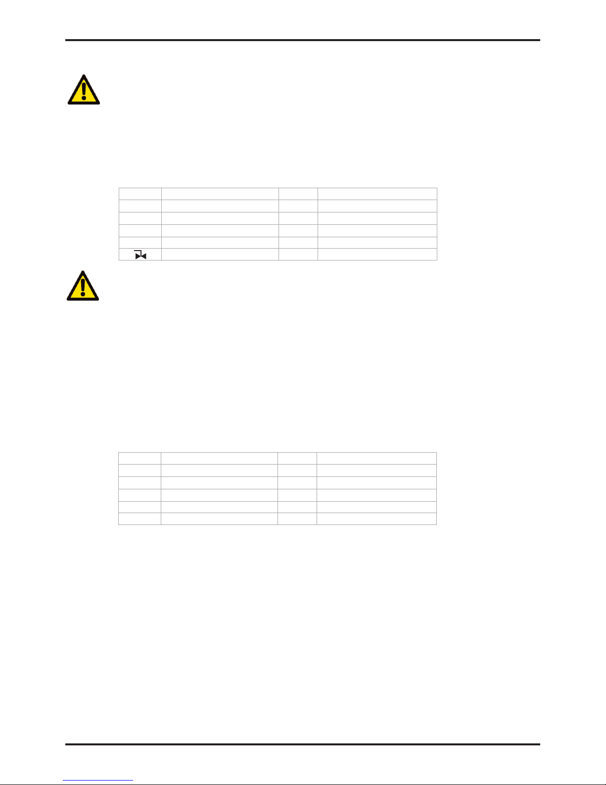
Diagram A6 in Annex A shows the configuration for a bank of 3 dryers.
3.2 Locating the equipment
Identify a suitable location for the equipment taking into consideration the minimum space requirements for maintenance and
lifting equipment as shown in diagram A5 in Annex A. When considering the final location of the equipment take into account
the noise generated when in use.
The dryer should only be lifted by the lower manifold using a fork lift truck or similar.
It is recommended that the dryer is secured to the base using the correct bolts through the support legs.
Ref Description Ref Description
1
Compressor
5 MX Dryer
2
Wet air receiver
6 Dust filter
3 Water separator 7 Bypass line
4 Dryer pre-filtration 8 Oil / Water separator
Isolation Valve
Caution
The use of a bypass line will allow wet untreated air into the system. It should therefore only be used in extreme
circumstances.
Ref Description Ref Description
1
Dryer Bank
6 Isolation Valves
2
AR grade filter (Outlet)
7 Inlet manifold
3 AA grade filter (Inlet) 8 Bypass line
4 AO grade filter (Inlet) 9 Outlet manifold
5 Water Separator
AA and AO grade filtration is recommended at the inlet to the dryer and an AR grade at the outlet. In extreme conditions a
water separator (WS) is recommended at the inlet.
Ensure that each filter condensate drain is suitably piped away and any effluent is disposed of in accordance with local
regulations.
When the dryers are installed in a multi-bank configuration as shown in diagram A6, they should be supplied from an end fed
manifold arrangement using long radius elbows and tee fittings.
It is important to ensure that all piping materials are suitable for the application, clean and debris free.. The diameter of the
pipes must be sufficient to allow unrestricted inlet air supply to the equipment and outlet gas / air supply to the application.
When routing the pipes ensure that they are adequately supported to prevent damage and leaks in the system.
The dryer is supplied with exhaust silencers and should be fitted prior to use. If the exhaust is to be piped away then a
minimum pipe size of 100mm (4”) should be used. This pipe should be fitted with a suitable isolation valve at the dryer
exhaust.
All components used within the system must be rated to at least the maximum operating pressure of the equipment. It is
recommended that the system be protected with suitably rated pressure relief valves.
3. Installation & Commissioning
3.1 Recommended system layout
The dryer should be installed with the correct pre-filtration and condensate management equipment to meet both the
specification and local environmental requirements.
Referring to diagram A4 in Annex A, the following equipment is recommended to meet these requirements:
Page 10
10
MX 102 - MX110 User Guide
3.4 Electrical Installation
Warning
A fully qualified electrical engineer must undertake all electrical work in accordance with local regulations.
The electrical supply cables should be connected to the dryer at the dedicated terminals as shown in diagram A7 in Annex A,
using the cable glands provided.
Warning
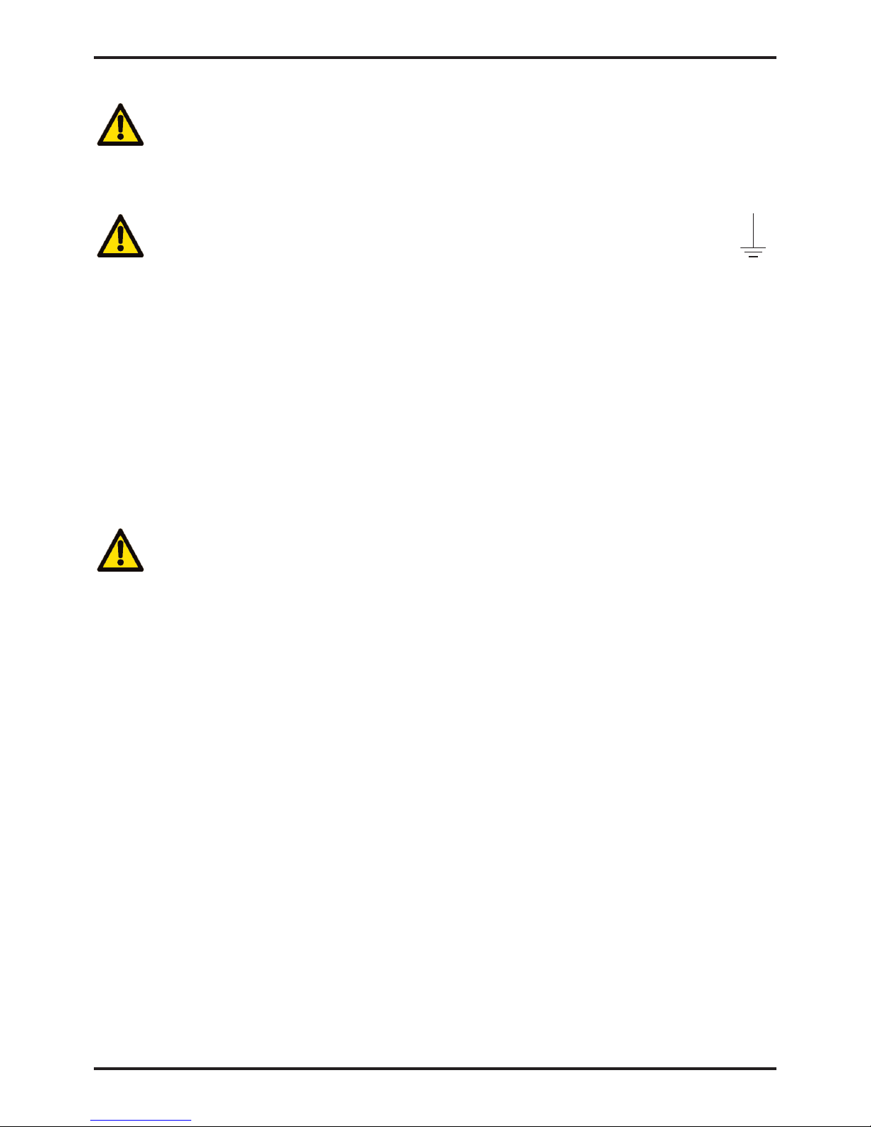
The dryer must be bonded to earth at the terminal marked with the international symbol IEC-60417 – 5017.
The dryer should be connected to the electrical supply through a switch or circuit breaker rated at 250VAC, 2A with a minimum
short circuit rating of 10KA. This device should be clearly and indelibly marked as the disconnecting device for the equipment
and located in close
proximity to the equipment and be easily accessible to the operator.
Overcurrent protection must be fitted as part of the building installation. This protection should be selected in accordance with
local and national code regulations with a maximum short circuit rating of 10KA.
3.4.1 Remote alarm indication
Each dryer is fitted with a set of volt free relay contacts designed for remote alarm indication and are rated 1A
max @ 250Vac (1A @ 30Vdc).
The alarm circuit should be connected between the “COM” and the normally closed terminals, “N/C” of the
relay. Under normal operation the relay will be energised and the alarm circuit will be open. When a fault
occurs, e.g. power failure, the relay will de-energise causing the alarm circuit to be complete.
The external alarm circuit should be connected to the dryer at the dedicated terminals as shown in diagram A8
in Annex A. using the cable glands provided.
Warning
If the remote alarm indication relay is used, the electrical enclosure will contain more than one live circuit. The relay
connections will remain live when the mains supply is disconnected.
3.4.2 MXS–DS Hygrometer connection.
The MXS – DS dryer operates on a variable cycle time controlled via a dewpoint dependent switching energy
management system. The hygrometer should be connected to the dryer at the dedicated terminals as shown in
diagram A9 in Annex A, using the cable glands provided.
3.4.3 MXA Analogue Outputs
The MXA dryer includes two sets of 4 – 20mA linear analogue outputs, which are used for the optional
re-transmission of the pressure and dewpoint readings. Connection to the outputs should be made at the
dedicated terminals shown in diagram A10 in Annex A, using the cable glands provided.
More detailed information is available in the MXA advanced controller addendum (dh Stock No: 178620002)
Page 11
11
MX 102 - MX110 User Guide
4. Operating the equipment
4.1 Overview of Controls
domnick hunter heatless desiccant dryers are available in a choice of three control options as shown below.
MXS
The display provides power supply and service interval indicators.
Please refer to diagram A11 in Annex A1.
MXS – DS
In addition to the power supply and service interval indicators the dryer comes complete with a digital dewpoint display and
associated uniit of measurement ºC / ºF flashes display poor dewpoint measurement interchanges with ECO when in DDS.
Please refer to diagram A11 in Annex A1.
MXA
The controller provides a complete system overview with an LCD status display screen and state of the art monitoring and
control.
Please refer to diagram A11 in Annex A1
More detailed information is available in the MXA advanced controller addendum (dh Stock No: 17862 0002).
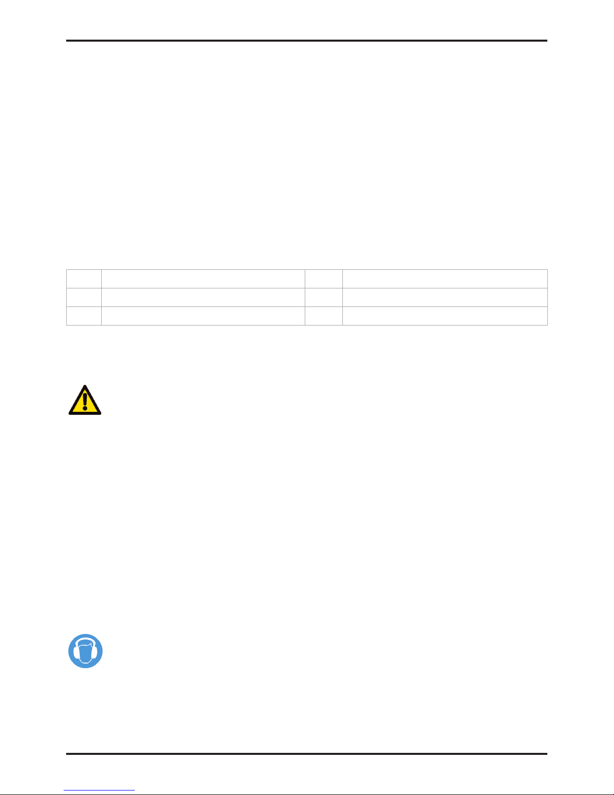
1 Power “ON” indicator 4 System status display LCD
2 Service interval indicator 5 Start / Stop and Reset controls
3 Dewpoint display 6 System navigation keypad
It is possible to upgrade the dryer from an MXS to an MXS-DS or to an MXA. Please contact your local domnick hunter
office for details.
4.2 Starting the equipment
Warning
Start-up should be undertaken by a domnick hunter trained, qualified and approved service engineer.
1. Ensure that the isolation valves on the inlet and the outlet of the dryer are closed.
2. Connect the electrical supply to the dryer and verify that the Power On indicator is illuminated.
3. Slowly open the isolation valve on the inlet of the dryer. Verify that there are no leaks.
4. Check that the system pressure relief valve is closed.
5. Test the condensate drains of the filters and verify that they are discharging correctly into a suitable collection vessel.
6. If the dryer has an MXA controller fitted, press the Start control, otherwise wait for the dryer to start automatically.
7. Slowly open the outlet isolation valve to allow the system to pressurise.
If a bypass line has been fitted, close the bypass valve.
No further intervention is required for normal operation.
4.3 Stopping the equipment
1. Close the isolation valve on the outlet followed by the isolation valve on the inlet.
2. De-pressurise the dryer by venting through the drain ball valve on the outlet dust filter.
Note: The drain valve should be opened gradually.
3. If the dryer has an MXA controller fitted, press the Stop control.
4. Disconnect the electrical supply to the dryer.
Note:- Small amount of air may be trapped between inlet isolation valve and dryer inlet.
Page 12
12
MX 102 - MX110 User Guide
5. Servicing
The recommended Service procedures identified in table 5.2 and all other repair and calibration work should be undertaken by a
domnick hunter trained, qualified and approved engineer.
5.1 Cleaning
Clean the equipment with a damp cloth only and avoid excessive moisture around any electrical sockets. If required you may
use a mild detergent, however do not use abrasives or solvents as they may damage the warning labels on the equipment.
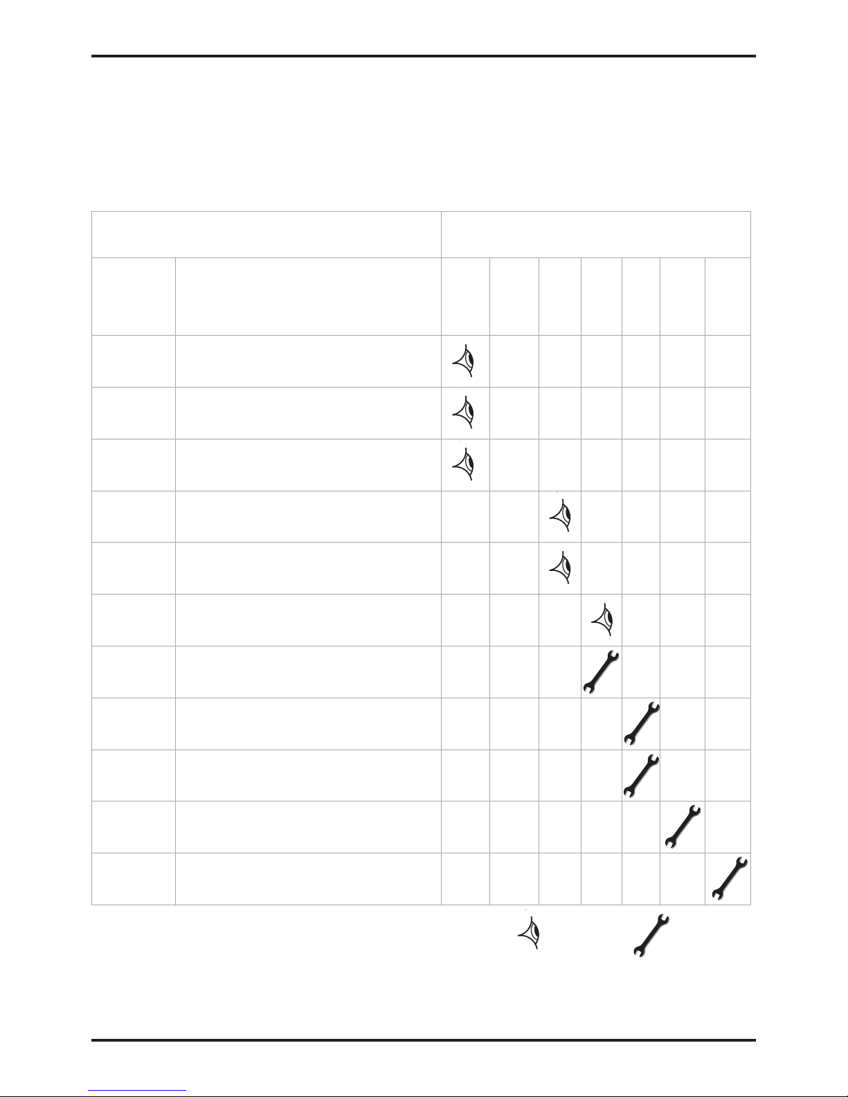
5.2 Service Intervals
Description of Service Requirements Typical Recommended Service Interval
Component Operation
Dryer Check POWER ON indicator is illuminated.
Dryer
Check STATUS / FAULT indicators located on the
controller.
Dryer Check for air leaks.
Dryer
Check the pressure gauges during purging for excessive
back pressure.
Dryer
Check the condition of electrical supply cables and
conduits.
Dryer Check for cyclic operation.
Dryer
Replace the active exhaust silencers
Recommended Service A
Filtration
Replace the inlet, outlet and control air filters, and
service drains.
Recommended Service B
Dryer
Replace / Calibrate dewpoint transmitter (DDS Units
only).
Recommended Service C
Dryer
Replace the valve seats and seals.
Recommended Service D
Dryer
Replace the Desiccant.
Recommended Service E
30 Months
24 Months
12 Months
6 Months
3 Months
Weekly
Daily
Check
Replace
Table 5.2
Page 13
13
MX 102 - MX110 User Guide
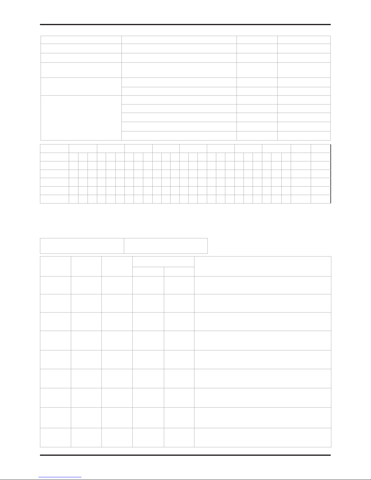
5.3 Service Kits
Service Kit Description Kit No Quantity
A - Silencer Service
Kit: Silencer Element MX 608620090 See table below
B - Filter Service
Refer to Filter user guide (171184000)
C - Hygrometer Service
Replacement dewpoint transmitter.
(DDS Units only)
608203580 1
D - Valve Service
Kit: Valve Overhaul <9 Barg 608620091 1
Kit: Valve Overhaul >9 Barg 608620092 1
E - Desiccant Service
AA 11.2 Litre Bag 608203661 See table below
MS 11.2 Litre Bag 608203662 See table below
WS 11.2 Litre Bag
608203663 See table below
Kit: Column Seals MX 608620098 1
Snow storm filler 608201051 1
MX102C MX103C MX103 MX104 MX105 MX106 MX107 MX108 MX109 MX110
-20 -40 -70 -20 -40 -70 -20 -40 -70 -20 -40 -70 -20 -40 -70 -20 -40 -70 -20 -40 -70 -20 -40 -70 -70 -70
Dryfill AA 9 8 13 12 16 14 21 19 26 24 31 28 36 33 41 37
Dryfill MS 1 7 2 11 2 13 3 17 3 21 4 25 4 29 6 30 37 42
Dryfill WS 2 3 4 5 6 7 8 9 10 11
Seals 1 1 1 1 1 1 1 1 1 1 1 1 1 1 1 1 1 1 1 1 1 1 1 1 1 1
Silencer 1 1 1 1 1 1 1 1 1 2 2 2 2 2 2 2 2 2 3 3 3 3 3 3 3 3
5.4 Service Record
Date of Commissioning
Service
(Hours)
Hours
Shown
Date
Serviced By
Comments / Observations
Print Initials
4,000
8,000
16,000
20,000
24,000
28,000
32,000
36,000
40,000
For servicing diagram please refer to A12 in Annex A1
Page 14
14
MX 102 - MX110 User Guide
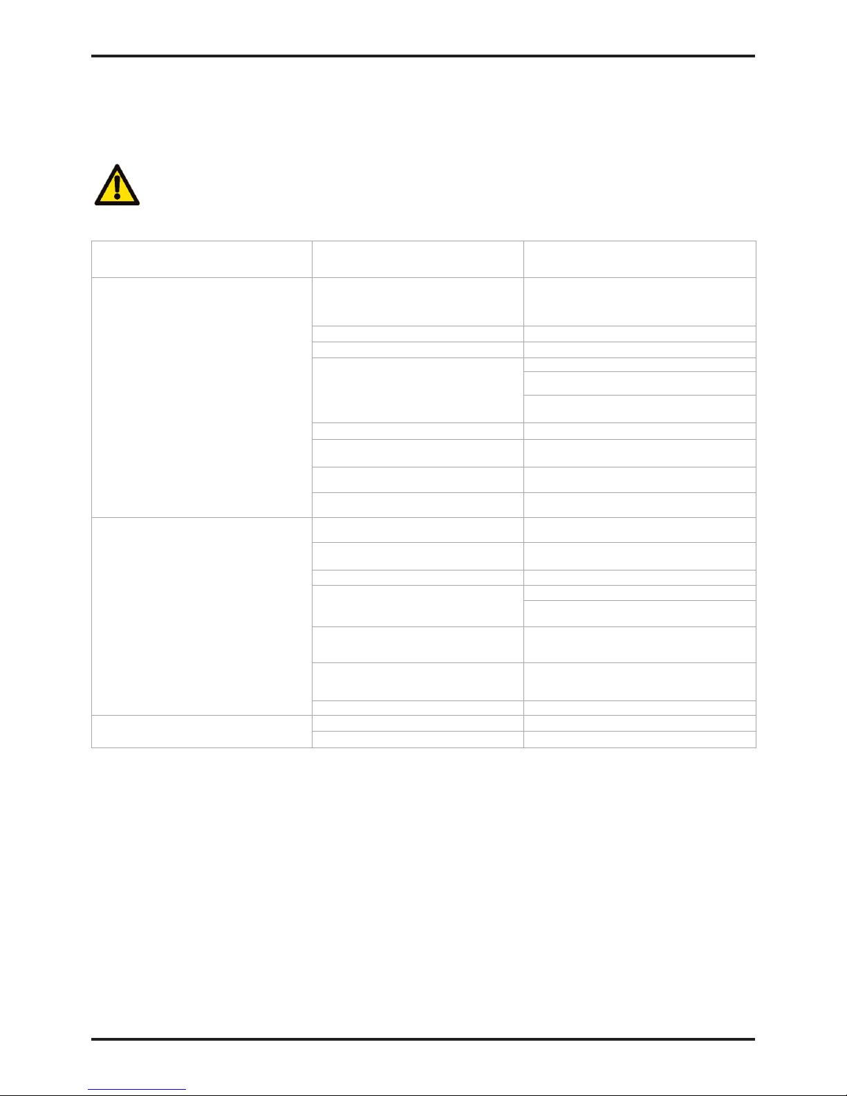
6. Troubleshooting guide
In the unlikely event that a problem occurs on the equipment, this troubleshooting guide can be used to identify the probable cause
and remedy.
Warning
Troubleshooting should only be attempted by competent personnel. All major repair, and calibration work should be
undertaken by a domnick hunter trained, qualified and approved engineer.
Problem Possible cause Action Required.
Poor dewpoint identified by water in the
downstream piping and equipment.
Dryer is operating outside of its sizing
criteria.
Check actual inlet parameters and
environmental conditions against the
values quoted at the time of sizing.
Bypass valve is open. Check bypass valve is fully closed.
Dryer has recently been started. Allow time for the system to “dry down”
The condensate is not being drained.
Check the condensate drain(s) for faults.
Check the drain hoses are free from kinks and
obstructions.
Ensure that the drain isolation valves
are fully open.
Regeneration column pressure > 350mbar. Replace the exhaust silencers.
Timer malfunction.
Contact domnick hunter approved
service agent.
Valve malfunction.
Contact domnick hunter approved
service agent.
Desiccant is approaching the end
of its useful life.
Contact domnick hunter approved
service agent.
High pressure drop resulting in low pressure
gauge readings or intermittent operation of
the downstream equipment.
The pre / after filtration is approaching the
end of its operational life.
Check and replace.
The dryer is being overflowed or is
operating at a reduced system pressure.
Check actual inlet conditions against the values
quoted at the time of sizing.
An isolation valve is partially closed. Check the position of all the isolation valves.
Pressure loss from the system.
Check the system for leaks.
Ensure that the drain cocks and
pressure relief valves are closed.
The dryer tripped due to power
supply interruption to the dryer.
Check that the dryer “POWER ON”
indicator is illuminated. If it is not
check the isolator and fuses.
The compressor tripped due to power
supply interruption to the compressor.
Check that the compressor “POWER
ON” indicator is illuminated. If it is not
check the isolator and fuses.
Isolation valve closed Check the position of the isolation valves.
Interruption of the air supply downstream
leading to a rapid loss of system pressure.
Compressor switched off. Check the compressor.
Fault shutdown event. Check the dryer fault indicators.
 Loading...