

Page 1

V100, V200 & V400
Operation and
Maintenance Manual
Page 2

Amendment Rec
ord
Issue 1 January 2008
2) 27864 Issue 1 January 2008
(
Page 3

CONTENTS
PART 1 : HEALTH & SAFETY........................................................................5
PART 2 : INSTALLATION..................................................................
PART 3 : OPERATION ......................................................................
PART 4 : MAINTENANCE & FAULT FINDING ..................................
APPENDIX A :TECHNICAL REFERENCE ........................................
...........15
...........71
......... 163
......... 251
APPENDIX B : EASYDESIGN MANUAL .................................................... 257
27864 Issue 1 January 2008 (
3)
Page 4

THIS PAGE INTENTIONALLY LEFT BLANK
4) 27864 Issue 1 January 2008
(
Page 5

PART 1 : HEALTH & SAFETY
CONTENTS
Page
EC DECLARATION OF CONFORMITY ........................................
GENERAL SAFETY.......................................................................
HAZARD INFORMATION..............................................................
Warning Notices .....................................................................................11
Caution Notices ......................................................................................13
............. 7
............. 9
........... 11
27864 Issue 1January 2008 (5)
Page 6

HEALTH & SAFETY
THIS PAGE INTENTIONALLY LEFT BLANK
6) 27864 Issue 1 January 2008
(
Page 7

HEALTH & SAFETY
EC DECLARATION OF CONFORMITY
(In accordance with ISO/IEC 17050-1)
Issuer’s Name: Domino UK Ltd
Issuer’s Address: Bar Hill Cambridge CB23 8TU
Objects of the Declaration: V100, V200, V400 Printers. Standard and FHE V-
Series Controllers
The Objects of the declaration described above are in conformity with the
requirements of the following D
irectives:
• 89/392/EEC : Machinery Directive as amended by 91/
368/EEC, 93/44/EEC,
93/68/EEC and 98/37/EEC
• 73/23/EEC : Low Voltage Directive as amended by 93/68/EEC
• 89/336/EEC : EMC Directive as amended by
92/31/EEC and 93/68/EEC
The
Following Standards have been used to show compliance:
• EN 61000
industrial environments.
• EN 61000-6-2, 1997: Generic standards section 2: Immunity for industrial enviro
• EN 61000-6-4, 2001: Generic standards section 4: Emission standard for indust
environments.
• FCC part 15 subpart B
• EN 55011, 1998+A1+A2: Limits and methods
characteristics of industrial, scientific and me
• EN 61000-3-2: 1995+A1+A2, Limits for harmonic
current up to and including 16 A per phase)
• EN 61000-3-3: 1995, Limits, limitation of voltage fluctuations and flicker
supply systems for equipment with rated current ≤ 16 A
• EN 61000-4-2, Electrostatic discharge requirements
• EN 61000-4-3, Radiated electromagnetic field requirements
• EN 61000-4-4, Electri
• EN 61000-4-5, Surge immunity requirements
• En 61000-4-6, Immunity to conducted disturbances, induced by radio frequency fields.
• ENV 50204, 1995 Radiated electromagnetic field from digital radio telephones.
-6-1, 1997: Generi
c standards section 1: Immunity for residential, commercial and light
of measurement of electromagnetic disturbance
dical (ISM) radio frequency equipment.
current emissions (equipment input
in low voltage
cal fast transient/burst immunity test; Basic EMC publication
nments.
rial
Signed for and on behalf of
Domino UK Limited, Bar Hill, Cambridge (December 2007)
27864 Issue 1January 2008 (7)
Page 8

HEALTH & SAFETY
THIS PAGE INTENTIONALLY LEFT BLANK
8) 27864 Issue 1 January 2008
(
Page 9

HEALTH & SAFETY
GENERAL SAFETY
p hine Safety Regulations.
The roduct is designed to conform to all current Mac
Note: Please read through this section before operating the machine.
This printer is designed for use with the following supply systems that conform to IEC
664 light industrial / domestic installation category II mains supply:
• ‘TN’ (any of following - TN-C, TN-S or TN-C-S) for example;
having one or mo
exposed conductive parts of the installation being connected to tha
protective conductors.
• ‘TT’ for example; a system having one point of the source of energy directly
earthed, the exposed conductive parts of the installation being co
earth electrodes electrically independent of the earth electrodes o
It is not suitable for connection to an ‘IT’ system for example; a system hav
direct connection between live parts and earth, the exposed conductive pa
installation being earthed. This therefore excludes any ‘phase to phase’ conn
supplies such as may be available in some factories and / or countries. If eit
fuse (located on the rear of the Controller, below the supply connector) is
must be replaced by a fuse 3.15/6.3AT - 230/115V – 50/60Hz - 300VA. Installation
must only be performed by qualified Domino personnel. For customer installa
authorisation must be obtained from Domino UK Ltd. All relevant Safety P
must be followed.
The printer and its component parts must onl
were sold, and for which they are designe
other functions.
Do not touch the printer or the controller with wet or damp hands.
Failure to do so may invalidate warranty.
re points of the source of energy directly earthed, the
y be used for the purpose for which they
d and constructed. No parts may be used for
a system
t point by
nnected to
f the source.
ing no
rts of the
ected
her supply
replaced it
tions
rocedures
Do not expose the printer or controller to rain.
Do not run the printer without ribbon material, as this may damage the
ALWAYS disconnect the power to the machine before removing any covers. You
must remove the plug from the mains power supply.
DO NOT insert body parts into the print head opening whilst the printer
as there is a danger that the mechanism will move without warning an
crushing h
DO NOT operate the machine with any covers removed. ALL covers must
place using the appropriate number of fasteners. It is essential that electrical a
electrical connector dust covers (provided with the machine) are fitte
connectors to protect against dust and dirt and possible static damage to internal
components.
Ensure all reasonable safety precautions have been undertaken. However, please ensure
that when working with / or around the machine, every care is taken to avoid
potential hazards. ALWAYS take great care around the machine not to slip, trip or fall;
especially if the machine is used in areas where the floor may be wet or greasy.
27864 Issue 1January 2008 (9)
azard.
print head.
is powered
d present a
be in
nd non
d to all unused
Page 10

HEALTH & SAFETY
If non Domino ribbon is used, it is recommended that anti static propert
considered. Domino U
K Limited cannot guarantee the safety and / or suitability of
ies are
non Domino print ribbon.
Take care, in the unlikely event of an e
lectronic fault causing an unexpected start up of
printer drive motors, to avoid possible injury.
If a verification scanner is used on this machine, please follow the manufac
procedures. When fitting and / or operating the scanner, follow th
e specifications as
turer’s safety
stated in the appropriate Laser Safety Standards (IEC825).
Please read the Manufacturers Safety Data Sheet (MSDS) for Isopropanol before using
the cleaning kit with any Domino product.
There is a danger of electrical shocks from the electrical outlet. All electro
nic checks
must be performed by qualified personnel.
There is a non replaceable lithium battery mounted on the Industrial PC. Under no
circumstances should thi
failure, please return the whole control board assembly to
s be replaced (it should last for several years). In the event of
Domino for repair. Please
note the following:
There is a danger of explosion if the battery is incorrectly replaced
.
Only Domino recommended replacements must be used.
Used batteries should be disposed of according to the battery manufacturer
’s
instructions.
The information above is correct to the best of our knowledge, information
at the date of this publication. The information given is d
esigned only as guidance for
and belief
safe handling use, processing, storage, transportation, disposal and release and is not
considered a warranty or quality specification. The information relates only to the
specific material designated and may not be valid for such material used in combination
with any other materials or in any process unless specified in text.
10) 27864 Issue 1 January 2008
(
Page 11
HEALTH & SAFETY
HAZARD INFORMATION
This section contains important notices. You must read these notices b
printe
r. The hazard information is prioritised into warning and caution notices as
follows:
Warning Notices
Warnin
notices clearly state th
avoided.
Handlin
Airborne particles
g notices denote a potential hazard to the health and safety of users. These
e nature of respective hazard and the means by which it can be
g the V200
The Cassette handle is for removing the cassette only.
be used as a means of carrying or holding the printer as this may
result in the printer becoming detached from the cassette causing
a crushi
Airborne particles and substances are a health hazard. Do not use
high-
ng hazard.
pressure compressed air for cleaning purposes.
It must not
efore using the
Heating element
The heating element and surrounding area become very hot
during
head, never touch the heating element area of the print head with
your fingers.
use. To avoid the risk of burns or damage to the print
Organic solvents
Cleaning fluid contains organic solvents, it is recommended to
wear suitable goggles and clothes to avoid contact with the eyes
and skin. Avoid inhalation of the vapour. Do not smoke in the
presence of the vapour.
27864 Issue 1January 2008 (11)
Page 12
Lethal voltages
Lethal voltages are present within this equipment w
connected to the mains supply. Only
personnel may carry out maintenance work.
HEALTH & SAFETY
hen it is
trained and authorised
Observe all statutory electrical safety codes and practi
is necessary to run the printer, disconnect the print
mains electrical supply service before removing the cover or
attempting any service or repair activity, otherwise death or
personal injury may result.
Compre
ssed air supply
To avoid the risk of injury to personnel or damage to the
equipment, do not exceed the flow and pressure specification.
Battery replacement
Replaceable batteries should only be replaced using
the same type and ra
explosion hazard.
Used b
manufactures instructions.
atteries should be disposed of according to the battery
ces. Unless it
er from the
batteries of
ting. Failure to do so may result in an
Fuses fire hazard
To ensure continued protection against the risk of fire, replace
fuses with the specified type and rating only.
12) 27864 Issue 1 January 2008
(
Page 13

Caution Notices
HEALTH & SAFETY
Cautionary notices denote a potential hazard to the physical integrity of
software but not a danger to personal. Thes
hazard and the means by which it can be avoided.
e notices clearly state the nature of the
equipment /
Damag e to Print Head
Changing the print head without setting the new resistance value
may cause severe damage to the print head.
Loss o
The counter values are not retained when the control box is switched off.
f Counter Data
The counter values are not retained when the control box is
switched off.
Equip ment Damage
To avoid the possibility of electric shock hazard and damage to
equipment. Do not fit or remove any connector on the printer
wh
ile the printer is switched on.
Cable Routing
To avoid damage to the cables or equipment, ensure that the
uted clear from any moving parts. cables are ro
Mains Supply Voltage
To avoid damage to the equipment, do not exceed the supply
voltage stated in the manual.
27864 Issue 1January 2008 (13)
Page 14
HEALTH & SAFETY
Cleaning Materials for Print Head
To avoid damage to the printer components, use only
brushes a
nd lint-free cloths. For cleaning we recommend using
cleaning kit.
Do not use high pressure air, cotton waste, abrasiv
metal
lic objects or degreasing cleaning fluids (e.g., Benzene,
acetone).
Spare Parts and Consumables
To avoid the risk of damage to the print head use only Domino
spares, parts and consumables.
Contact your supplier for
les and Service contact:
For sa
Domino UK Ltd.
details.
soft
e materials,
Bar Hill
Cambridge CB23 8TU
Tel: (01954) 782551
Fax: (01954) 782874
© DOMINO UK LTD 2007
14) 27864 Issue 1 January 2008
(
Page 15

PART 2 : INSTALLATION
CONTENTS
UNPACKING ............................................................................................
FHE Controller Main Parts ..........................................................
STD Controller Main Parts ..........................................................
V200 Printer Main Parts ..............................................................
V100 Printer Main Parts ..............................................................
V400 Printer main parts...............................................................
V200 Printer - Optional Bracket...................................................
V100 Printer - Optional Bracket...................................................
V400 - Optional Manual Bracket.............................................................
V400 - Optional Automatic Bracket .............................................
MECHANICAL INSTALLATION.....................................................
Installation Requirements............................................................
Installation ...................................................................................
Electrical FHE controller I/O Connection to a host machine........
...........20
...........21
...........22
...........23
...........24
...........26
...........26
...........29
........... 30
...........30
...........31
...........32
Page
17
28
Electrical FHE controller I/O Connection to a host machine........
STD controller I/O Connection to a host machine .......................
SETTING UP THE FIRMWARE ...............................................................
Saved in Design ..........................................................................
Print Counter ...............................................................................
System ........................................................................................
Time / Date..................................................................................
Error / Warning............................................................................
System Variables ........................................................................
International ...........................................................................................43
Hardware................................................................................................44
Diagnostics.............................................................................................45
I/O Test ..................................................................................................46
...........33
...........34
...........35
...........36
...........37
...........38
...........39
...........42
35
27864 Issue 1January 2008 (15)
Page 16

Sensor Test............................................................................................47
Interface ......................................................................................
Serial Communication .................................................................
I/O Settings .................................................................................
Network .......................................................................................
Network IP Address.....................................................................
Network Host Name ....................................................................
Network ODBC Service...............................................................
...........49
...........50
...........51
...........53
...........54
...........55
...........56
Printer Type............................................................................................
Admin ..........................................................................................
Users and Passwords .................................................................
Users and Passwords, Advanced................................................
...........59
...........60
...........64
Signing Setup.........................................................................................65
Logging ..................................................................................................67
57
(
16) 27864 Issue 1 January 2008
Page 17
INSTALLATION
UNPACKING
The printer can be delivered with tw
• FHE (For Harsh Enviro
• STD (Standard) Controller.
Before installation, it is importa
damaged during shipment, and that all parts needed for the installation and
operation of the printer are present.
o different controllers:
nment), or
nt to check that the printer has not been
Ensure that the following i
STD Controll
Contents Part No.
1 x STD Controller VEP4065E
1 x Cable Printer Power and signal Y1196 VE
1 x Cable for Main Power supply Area Specific) VEYxxxx (
1 x Cable for I/O 15 pin connection VEY0168
er Inventory
tems are present.
1 x Cable Serial VEY1191
1 x V Series Manual 27864 (English)
1 x 128 Mb Compact Flash memory card VEY0527
27864 Issue 1January 2008 (17)
Page 18
INSTALLATION
FHE Controller Inventory
Contents Part No.
1 x FHE Controller VEP4063E
1 x Cable Printer Power and signal 96 VEY11
1 x Cable for Main Power supply Area
VEYxxxx (
cific)
Spe
1 x Cable for I/O 16 pin connection Y0195 VE
1 x Cable Serial VEY1193
1 x Encoder Adapter VEY1197
1 x V Series Manual 27864 (English)
1 x 128 Mb Compact Flash memory card VEY0527
FHE Optional Accessories Inventory
Contents Part No.
Network Adapter Type VEY1185N
Keyboard Adapter Type VEY1185K
Network/Keyboard Adapter Type VEY1185NK
(
18) 27864 Issue 1 January 2008
Page 19

INSTALLATION
Printer Unit Inventory
Contents Part No.
1 x Printer unit s on type Depend
1 x Cleaning kit Type VPR0222
1 x Air pressure regulator
1 x 3 meter 6mm air tube Type VEY0786
1
AS1001 Type V
1
Not for V200 printer unit, as this model has a built in air regulator.
27864 Issue 1January 2008 (19)
Page 20

FHE Controller Main Parts
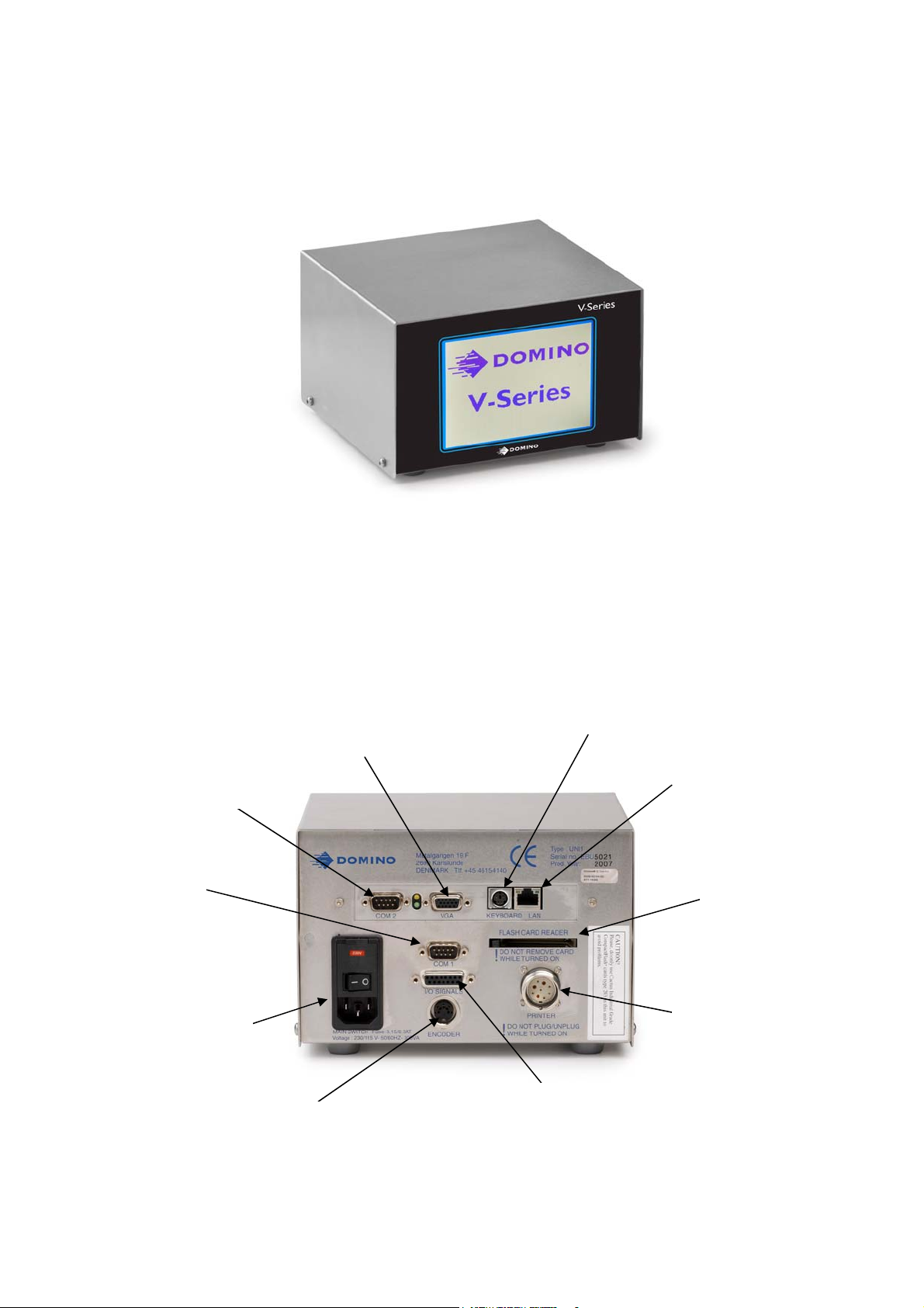
CONTROL BOX (front view)
Touch screen
Power supply
230/115 V a.c.
INSTALLATION
Optional Network and /
Keyboard connection
or
I/O Connection
Printer Connection
Serial Communication
RS232
Control box with touch screen, slots for the flash memory card, and all connectors for
external input.
Encoder
CONTROL BOX (right side)
Power Supply
On/Off
Compact Flash Card
Slot <512Mb
(
20) 27864 Issue 1 January 2008
Page 21
INSTALLATION
STD Controller Main Parts
Allows the creation of labels, programming and electronically control machine
handling and receive all internal service instru
Com 2 Serial
RS232
cessible) (Not ac
Com 1 Serial
RS232 Input
Control Box with the LCD touch screen display (IP20 Protec
ctions in text and pictures. Label design
iewed b g, without ha ed.
efore printin
PC Screen VGA
Connection
ving a printer connectcan be prev
Keyboard Connection
tion)
LAN
Compact
Flash
Card Slot
Power Supply
230V a.c./115V a.c.
2786
V100 and V200 model
4 Issue 1January 2008 (21)
Encoder
only
I/O Input
(Packaging Machine)
Printer Connection
LAN
Page 22
INSTALLATION
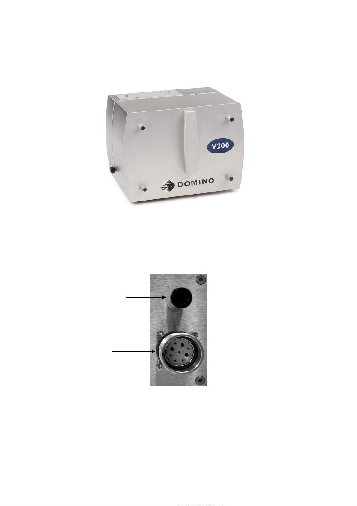
rts V200 Printer Main Pa
Air pressure inlet port
(clean dr
Connection to
controller
y air)
V200 Printer Unit
tions (rear view) Printer Connec
(
22) 27864 Issue 1 January 2008
Page 23
INSTALLATION
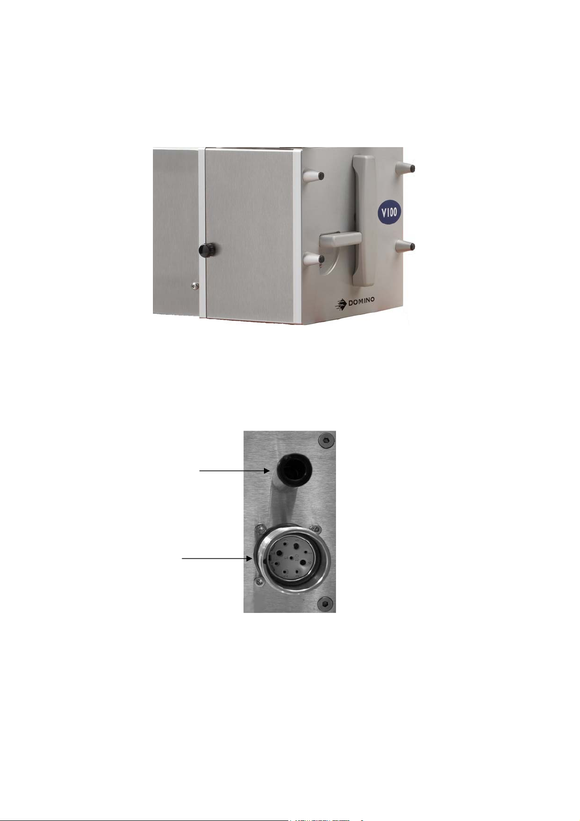
V100 Printer Main Parts
V100 Printer Unit
Printer Connector Plate (rear view)
Pressure air inlet port
(clean dry air)
Connection to
controller
4 Issue 1January 2008 (23)
2786
Page 24
INSTALLATION
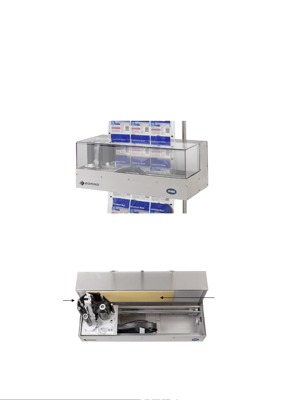
V400 Printer main parts
The system offers a wide range of printing options.
V400 Printer Unit
V400 Printer front view with cover removed
Ribbon
Web
Platen
(
) 27864 Issue 1 January 2008
24
Page 25
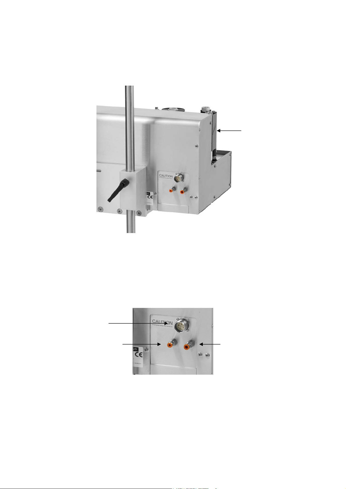
V400 (rear view)
INSTALLATION
Ribbon
Web
V400 Connections (rear view)
Connection to
Controll er
Open exhaust from
the solenoid valve.
Ø 4 mm
(for special GMP
regulation)
Air pressure input
max 6 bars. Ø 6
4 Issue 1January 2008 (25)
2786
Page 26

INSTALLATION
V200 Printer - Optional Bracket
Standard Bracket System
The Standard Bracket System ensures a safe
machine, and makes it eas
Type: VEP 56XXXX (where XXXX range
Standard Intervals are 100mm
y to set up and adjust the printer according to requirements.
mounting of the printer on the packaging
s from 400 to 1300mm).
V100 Printer - Optional Bracket
Standard Bracket System
The Standard Bracket System ensures a safe mounting of the printer on the packaging
machine, and makes it easy to set up and adjust the printer according to requirements.
Type: VEP 51XXXX: (where XXXX ranges from 400 to 1300mm.
Standard intervals are 100mm.
(
26) 27864 Issue 1 January 2008
Page 27
INSTALLATION
Bracket System with Optional Web Positioning S
ystem
The Web positioning system (shown here below the bracket) can be used i
intermittent applications to vary
the position of the web relative to the print position.
n
It fits to the standard bracket system.
Web positioning
System
Web positioning system: Type: VASWP – XXXX (where X ranges from 400 to
1300mm).
Standard Intervals are 100mm
4 Issue 1January 2008 (27)
2786
Page 28

INSTALLATION
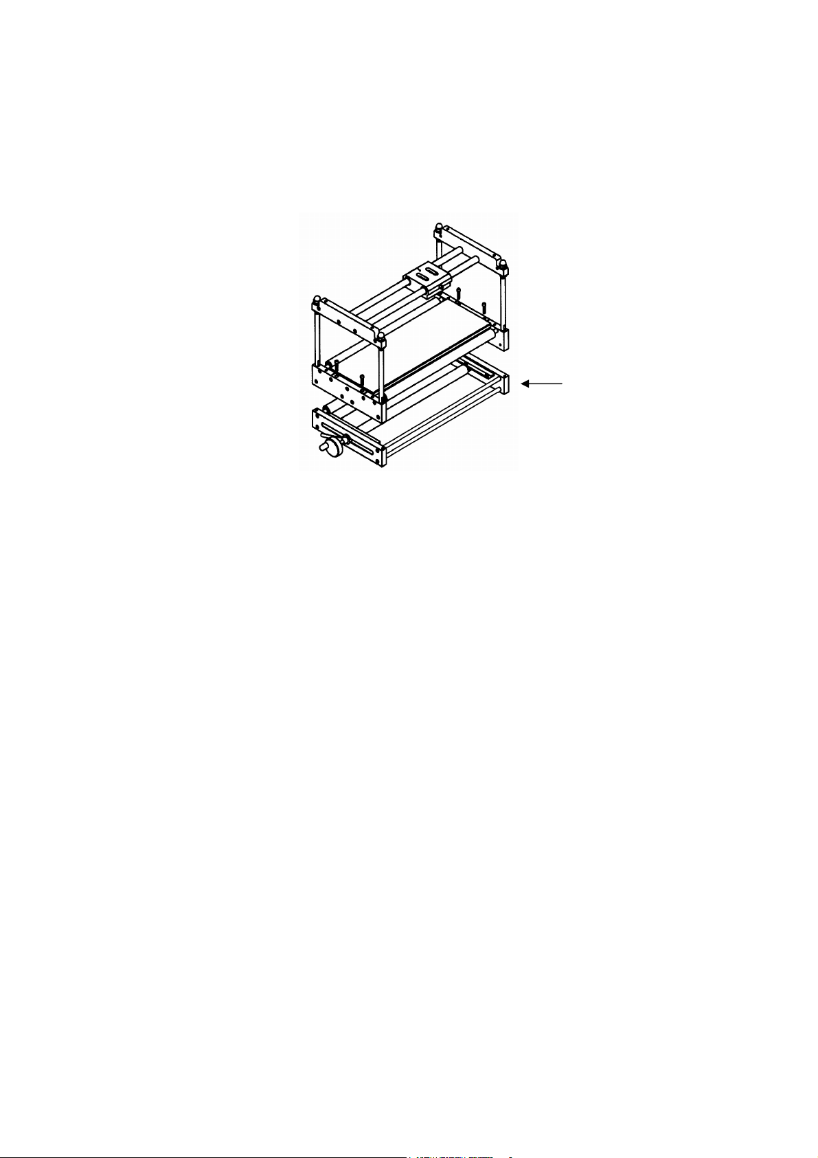
V400 - Optional Manual Bracket
Manual Bracket System
Bracket parts.
1. Mounting plate for the V400 printer
2. Packaging machine large mounting angle
3. Packaging machine small mounting angle
The Manual Bracket System ensures a safe mounting of the printer on the packaging
ma ne, a akes to set up and adjust the printer according to requirements.
chi nd m
Bracket Sy
stem for V400:
it easy
Type: VASHBTM100X (where X determines the width)
X Min. Max.
Width Width Width
4 750
610 mm
mm
5 490 mm 630
mm
6 730 mm 870
mm
(
28) 27864 Issue 1 January 2008
Page 29
INSTALLATION
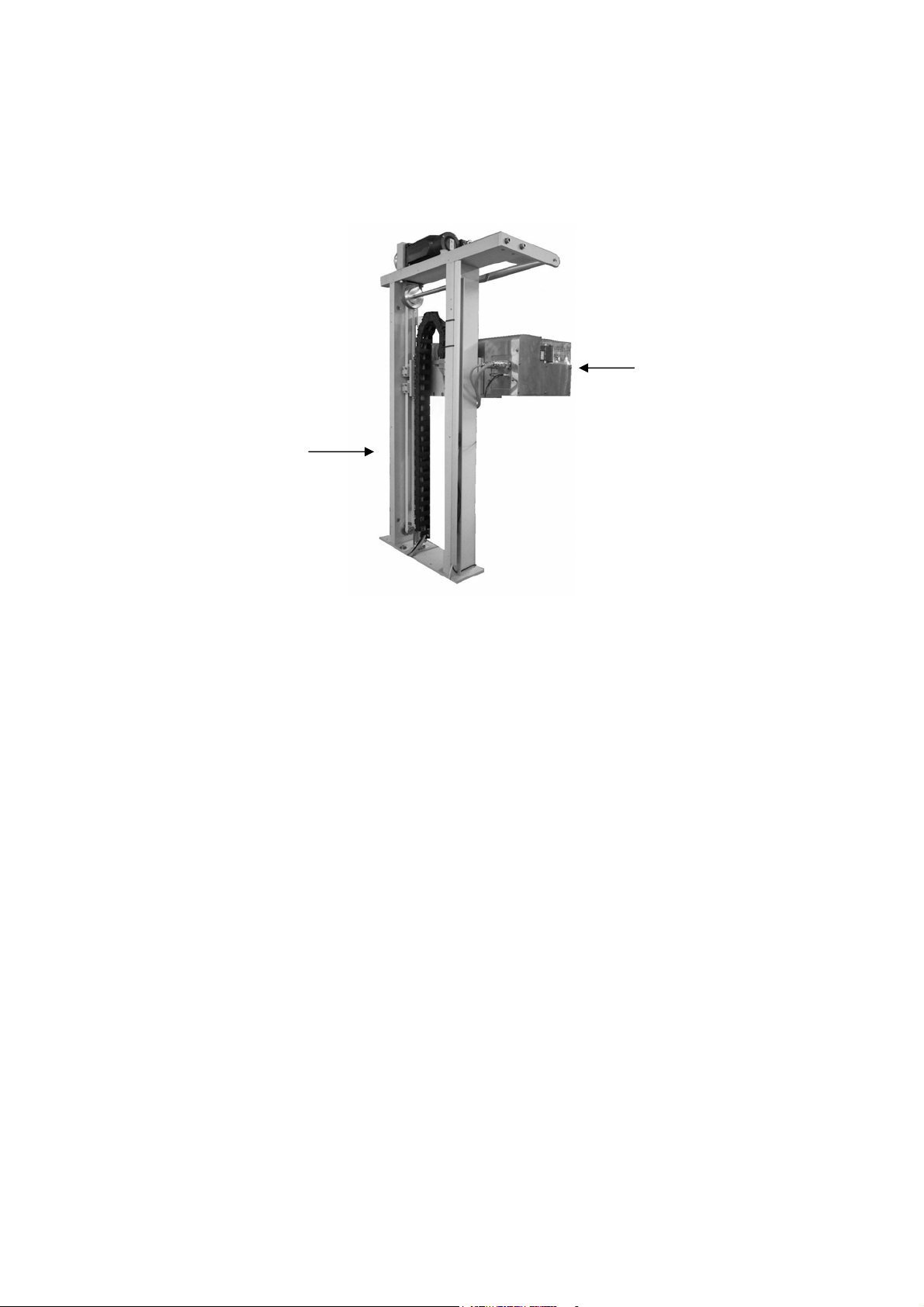
V400 - Optional Automatic Bracket
Automatic Bracket System
Automatic
Bracket
V400 Printer
The automatic bracket system allows the V400 printer to print over a larger area
during each printing cycle (whilst the material to be printed remains station
The automatic bracket moves the printer vertically in steps after each horizontal stroke
of the printer.
The bracket uses a stepper moto
a dedicated control module which uses signals from the V Series cont
packag
The automatic bracket comprises of unguarded moving parts and must be installed to
ensure a safe operating environment.
The automatic bracket is supplied with installation guidelines and an operations
manual.
ing machine.
r to drive the vertical movement and is controlled via
ary)
roller and
4 Issue 1January 2008 (29)
2786
Page 30

INSTALLATION
MECHANICAL INSTALLATION
Installation Requirements
Ensure that the following services and control sig
(1) Power - 115/230 Vac (+10%, -15%) 50/60Hz
(2) Compressed Air - 6 Bar (max.), dry, uncontaminated.
(3) A print start signal - this has to be a vo
printing is required.
(4) Sufficient space for installation and operation.
(5) If using a V200 an encoder to monitor the substrate speed is required.
nals are available:
.
lt free contact which closes when
(
30) 27864 Issue 1 January 2008
Page 31

INSTALLATION
In ts allation
(1
) Mount the printer in the bracket system.
Note:
If mounting is a V200 ensure the print head is mounted on the top point of the
rubber roller.
(2) Adjust the nuts on the 4 shafts of the brac
rubber plate / rubber roller and the print head.
On the V100 printer the distance should be between 1 and 1.5mm
•
• On the V200 the distance should be between 0.2 to 1.0mm.
V100
1.0 - 1.2 mm
ket to the correct distance between the
V200
0 - 1 mm
0.2 - 1 mm
27864 Issue 1January 2008 (31)
Page 32

INSTALLATION
(4) Connect cables.
• Connect the main cable from the controller to the main supply
• Connect the printer cable between the printer and the controller
• Conn
ect the air pressure to the printer and adjust to 2.5 Bar (5 inch printer:
3.5 Bar)
• If a V200, con
nect the encoder.
(5) Turn on the controller.
(6) Put ribbon on the cassette. Follow the instruction inside the c
Load the test design from the design library
(7)
assette.
(8) Carry out a test print as described below.
• V100 only - when printing with the V100 printer push the
test print on
the touch screen
• V200 only - when printing with an CM or V200 run the web on the
packaging machine with 300 mm / s. (note: the start signal must be in
continuous mode)
• Only V200 - If the quality of the print is equal to the print
ou
with the printer then reduce the contrast until the quality is redu
(approximate 10% reduction)
• Only V200 - Fine adjust the print head position according to th
point on the rubber roller. Do the adjustment in steps of a half tu
screw, adjust, run and check again. The adjustment has to be tr
directions depen
may need to be reduced several times in this procedure. Con
adjustmen
t until the best result has been found. The mechanical adjustment
ding on the quality of the packaging material; the contrast
tinue with this
of the printer has now been found and further adjustment of the printer is
not needed anymore
• Only V200 - Increase the contrast until an acceptable quality has been
achieved.
t received
ced
e top
rns on the
ied in both
Head position
screw
(
32) 27864 Issue 1 January 2008
Locking screw
Page 33

INSTALLATION
Electrical FHE controller I/O Connection to
machin
Use Cable VEY0195
Vcc
Vcc
Vcc
Vcc
e
Start Signal
Ribbon Tension
Print Ready Signal
Printer Error Signal
Ribbon Warning Signal
Park out Signal
Max voltage: 30V DC
Max current: 100mA
Input Signals
Signal length min 50ms
Input
Start Signal
24V+
1 Red +
2 Grey 2
_
24V+
5 Black + 5
6 Yellow 6
_
Output
+
15 Blue + 15 Ready
_
16 Green 16 Closed when ready
13 White / Yellow + 13 Error
+
14 Yellow / Brown 14 Closed when no error
_
11 Pink + 11 Ribbon Warning
+
12 Violet 12 Open when low ribbon
_
9 Park (V400 only)
9 White / Green Signal is closed when
+
10 Brown printer is in park osition
_
10 Auto bracket output
To use this output (10), the automatic bracket must
be enabled
K1
Ribbon Tension
K2
K1 and K2 wire length
Output Signals
a host
NPN
or
NPN
or
p
4 Issue 1January 2008 (33)
2786
Page 34

INSTALLATION
STD controller I/O Connection to a host machine
Use Cable VEY0168
Start Signal
Ribbon
Tension
Vcc
Vcc
Vcc
Vcc
Print Ready Signal
Printer Error Signal
Ribbon Warning Signal
Park out Signal
Max voltage: 30V DC
Max current: 100mA
+
_
Input Signals
Signal length min 50ms
Input
Start Signal
24V+
5 Yellow +
13 Black / White 13
_
24V+
7 Blue + 7
15 Red White 15
_
Output
4 Orange + 4 Ready
12 Light Green 12 Closed when ready
3 Red + 3 Error
+
11 Pink 11 Closed when no error
_
2 Brown + 2 Ribbon Warning
+
10 White 10 Open when low ribbon
_
1 Park (V400 only)
1 Black Signal is closed when
+
9 Grey printer is in park posit
_
9 Auto bracket output
To use this output (9) the automatic bracket must be
enabled
K1
Ribbon Tension
K2
K1 and K2 wire length
Output Signals
NPN
or
NPN
or
(
34) 27864 Issue 1 January 2008
Page 35

INSTALLATION
SETTING UP THE FIRMW
ARE
Saved in Design
Find "Save in design" in the "Settings / Run" menu.
This menu allows you to defi
is examined in detail below:
It can sometimes be useful to store some of the settings directly in the design
A scenario could be that design1 uses a low contrast setting but a high start
while design2 requires a high contrast but a low
both contrast and start pulse offset every time the specific design is loaded, t
values for these settings can be stored with the design.
Use the menu below to define which setting you wish to be stored in the design files.
ne the settings you wish to save in the design. The menu
files.
pulse offset,
start pulse offset. Instead of changing
he optimal
1
(1) Settings
This shows the user a complete list of all the settings in the printer that can b
with the individual design. Pressing on the desired settin
"CONTRAST”) will select that item. By pressing the "Toggle” button (in the bottom
right-hand corner), and then "Save”, the selected setting will be saved with each
individual design.
If "CONTRAST” is subsequently altered in a design and the design is then loaded, the
CONTRAST value will update the global CONTRAST value.
g (in the example above:
e saved
4 Issue 1January 2008 (35)
2786
Page 36

Print Counter
INSTALLATION
The system supports t
defined amount of prints.
he use of a print counter. That means it can be used to print a
1
3
(1) Enable prompting of print coun
If this check box is selected, the system will prompt the operator (when a j
manually started) for the number of prints to do. The prin
manually ended (or the print is otherwise interrupted).
ter
ting will continue until
2
ob is
Please note that this setting only applies to a print job started on the printer itself. If a
design is transferred, the sender determines the "number of prints”.
) Action when done
(2
Use this field to define what should happen when the required number of prints has
been printed.
The options are:
• Quit print: Unlo
• Restart print: Restart
selected)
• b, when the last
Ask: The operator is asked whether to restart or unload the jo
print has been printed.
ads the print job when the last print is printed.
s the print job (a new number of desired prints must be
(3) Protect print memory
If enabled, a print in the print memory cannot be overwritten by an
external source. To load another print job, the current job must be
(manually) unloaded first.
(
36) 27864 Issue 1 January 2008
Page 37

INSTALLATION
System
The “System” menu is a configuration menu where the user must s
information needed by the printer to function optimally. These in
language, keyboard layout, all of which should be configured in this men
This menu will normally only be used upon installation of the printer, an
recommended to go through this menu before starting the printer for the first time.
et up some of the
clude; date,
u.
d users are
1
2
3
4
(1) T
Here the user can set
menu is the time used
page 38.
ime/Date
the time and date in the printer’s system. The time set in this
by the printer when calculating the various types of RTC. See
(2) Error/Warning
The menu allows the user
”Error”, e.g., when the printer should display a message when the ribbon
close to being used up. See page 39.
(3) System va
This menu is used to define the printer’s ID. If the printer is required to p
ACHINE ID), this ID must be set before it can be inserted as a variable. See page
(M
42.
riables
to define when the printer should send a ”Warning” or an
is getting
rint its ID
(4) International
This menu allows the user to define keyboard set-up and printer language. See page
43.
4 Issue 1January 2008 (37)
2786
Page 38

INSTALLATION
Time / Date
The time and date in the printer can be set here.
1
2
(1) Set Time
Define the printer’s time here.
local time.
Pressing “Set Time” will allow the user to key in the
(2) Set Date
Set the date in the printer system here. Pressing “Set Date” will allow the user to alter
the date.
(
38) 27864 Issue 1 January 2008
Page 39

Error / Warning
INSTALLATION
This menu allows users to determine when the printer should send a
message. The difference between “Warning” and “Error” is that in th
“Warnin
operating.
In the case o
operating.
To switch from “Error” to “Warning” simply press the button.
g” the user will be informed on the screen but the printer will carry on
f “Error” the printer will display an error message on screen and stop
4
warning or error
e case of
1
2
3
(1) T
The “Error/Warning” menu contains two screens that the user can scroll between. By
pressing the right-han
pressing the left-hand arrow key, the user will be returned to the previou
disp
he arrow keys
d arrow key the user will come to the next screen display. By
s screen
lay.
(2) Ribbon Alarm
When the ribbon is broken, the system has tw
fault.
• A dancer arm act
• The ribbon roll has not r
though a certain amount of ribbon was used.
(3) Ribbon Warnin
When the ribbon roll is almost empty the ribbon-warning feature is activated (the
ribbon warning output is activated).
By setting this feature to “Error” the printer will stop when the diameter of the
ribbon roll is equal to the value set in the "Activate ribbon warning when
diameter is below:" field.
ivates the ribbon alarm sensor
otated (measured by the ribbon warning sensor) even
g
o independent ways of detecting the
4 Issue 1January 2008 (39)
2786
Page 40

INSTALLATION
3
5 4
This item is described below. If ”Ribbon Warning” has been set to ”Warn
warning will be displayed on screen when the ribbon has reached the d
"Activate ribbon warning when diameter i
Activate ribbon warning when diameter is below
This menu is used to set the minimum diamete
together with “Ribbon Warning” (described above).
When ribbon diameter reaches the set value, the “Ribbon Warning” function is
activated. The most suitable diameter is based on the printer’s speed and the size of the
print.
s below:" (see next paragraph):
r of ribbon roll. The menu is used
ing”, a
iameter set in:
(4) Default
The default button allows you to r
To do this, press the “default” button once.
Notice that the button is now reversed
When the default button is reversed, press the setting you wish to reset.
If you have accidentally pressed the default button, press it again to deselect it.
eset a single setting to the factory default.
1
2
6
(1) The arrow keys
The “Error/Warning” menu contains two screens that the user can scrol
pressing the right-hand arrow k
pressing the left-hand arrow the user will be returned to the previous screen
ey the user will come to the next screen display. By
(2) Print pulse when not ready
If the packing or labeling machine sends a signal whilst the printer is calculating, an
error/warning as follows can be set:
l between. By
display.
Error: If the printer is interrupted by a signal during printing, retraction, or calculating
the next label, pause or not ready, it will stop.
(
40) 27864 Issue 1 January 2008
Page 41

INSTALLATION
Note: if the printer is interrupted by a signal during printing, retraction or calculating
label, pause, not ready, it will ignore the signal. The system will first accept the
it has finished calculating. Thus producti
exceeded (but some products may miss a print).
(3) Spe
(CM-Types)
If the web speed is below 50 mm/s, a warning or error signal will be displayed on the
screen, in accordance to the settings.
ed too low
on will not halt if the printer’s maximum speed is
the next
next signal when
(4) Abort print when speed too low
(CM-Types)
By selecting the field, the printer will abort the current print
the setting is unselected t
web is started again, the r
he printer remains in its current print position and when the
emains of the current print is finished.
if the speed is too low. If
(5) Y-offset too short
If the distance between the label start and the first line are too short, a warn
al will be displayed on the screen. If the Y-offset is too short the print head cannot
sign
print the firs
standards. Th
print.
t pixels and hence the print may not comply with the desired quality
e minimum Y-offset depends on the print speed and the actual design to
ing or error
(6) Default
The default button allows the user to reset a single setting to the factory default. To
do this press the “default” button once.
Notice that the button is now reversed. When the default button is reversed, press the
setting you wish to reset.
If the default button was accidentally pressed, press it again to deselect it.
27864 Issue 1January 2008 (41)
Page 42

INSTALLATION
System Variables
1
2
(1) Machine ID
Use this setting to assign a name to the printer. It is this name that the machine id
(identity) vari
able (page 133) refers to.
Please do not confuse the machine id w
ith the host name (see page 55).
(2) Hotstart
The system has limited hot start functionality.
When ever a design is loaded, the name of the design and all entries for pro
variables are stored on the internal system drive. W
the information is purged from the internal system drive.
If the system is switched on, th
any design being printed. If such information is found, the design in question is loaded
and any prompted variables will automatically be filled in.
Please note that any counters and real time variables in the design is initialised as it
would be during a normal job load.
e internal system drive is searched for information about
hen the design is unloaded again,
mpted
(
42) 27864 Issue 1 January 2008
Page 43

INSTALLATION
International
The screen below shows the ”International” menu
1
2
(1) Printer language
Defines the language the V Series Controller User Interface should use. By pressing on
the “English” fi
which the user may select the desired language.
eld in the above illustration, a dropdown list will be displayed from
(2) Keyboard
The user can set the keyboard appropriate to
“English (UK)” field in the above illustration, a dropdown list will be displ
which the user can select the appropriate keyboard layout.
The keyboard is used when designing your print and it is therefore important that this
setting is defined before beginning to design prints.
It is possible to temporarily change the keyboard layout when the keyboard is
displayed.
the printer language here. By pressing the
ayed from
4 Issue 1January 2008 (43)
2786
Page 44

INSTALLATION
3
Hardware
The next tab is the "Hardware” menu.
1
2
(1) Diagnostics
Should problem
the testing of some of the functions necessary for operation of the printer.
s arise in connection with the printer, the ”Diagnostics” item allows
(2) Interface
All connections to
must be defined under “INTER
the surrounding environment (be it a packaging machine or a PC)
FACE”.
(3) Printer Type
Select the printer model connected.
(
44) 27864 Issue 1 January 2008
Page 45

Diagnostics
INSTALLATION
1
2
3
(1) I/O test
Use this menu to verify the interface to the pa
(2) Sensor test
Use this menu to verify the sensors on the
(3) Speed
Use this menu to measure the speed of the web.
The menu will further display information about the voltage to the print head and
stepper motors.
Finally, the menu will show the current temperature of the print head.
/ Voltages / Temperatures
ckaging machine.
print unit.
4 Issue 1January 2008 (45)
2786
Page 46

I/O Test
1
INSTALLATION
2
3
(1) Input
The input co
open or closed.
lumn shows the status of the four inputs to the system. Possible values are
(2) Output
Use the buttons to force the output to either open or closed (simply press the output
you wish to change).
(3) Loop test
The loop test requires the use of a special cable (loop cable) that will test the unit’s
input/output signals.
(
46) 27864 Issue 1 January 2008
Page 47

INSTALLATION
Sensor Test
The menu display reflects the actual printer attached (the screen below is for a V200
printer)
Ribbon Alarm
The ribbon alarm is acti
manually activate th
verify that the sensor is activated.
vated if the dancer arm reached this reflective sensor. To
e sensor, place something reflective in front of the sensor and
Ribbon Warning
The ribbon-warning sensor monitors the rotation of the roll with unused ribbon. Use
a piece of pape
On some models, the ribbon warning is a reflective senso
turn the roll of unused ribbon and verify that the sensor is activated.
r to block the fork sensor and verify that the sensor is activated.
r. On these models, simply
Printer Open
Open and close the cassette and verify
that the sensor is activated.
Encoder
Activate the enc
pulse from the encoder (12 pulses per mm).
The speed test can be used to verify the function of the encoder.
oder and verify that the screen changes. The screen changes for each
Start Winder
(V200 printer only)
Printer has a reflective sensor that monitors the second dancer arm’s position. Place
something reflective in front of the sensor and verify the sensor is activated.
27864 Issue 1January 2008 (47)
Page 48

Stop Winder
(V200 Printer only)
INSTALLATION
Printer has a reflective sensor that monitors the second dancer arm
’s position. Place
something reflective in front of the sensor and verify the sensor is activated.
(
48) 27864 Issue 1 January 2008
Page 49

Interface
3
INSTALLATION
All connections to
must be defined here.
the surrounding environment (be it a packaging machine or a PC)
(1) Serial Communication
Use the serial com
system. The serial port can be used to connect a PC, scale or other de
munication menu to define the behavior of the serial port of the
1
2
4
vice.
(2) I/O Set
Use the I/O settings menu to set up the in
(3) Netw
Ethernet LAN Set-up, u
Ethernet can be used to transfer designs and to remotely control th
(See page 53)
tings
terface with the packaging machine.
ork
sed to set-up IP address.
e printer.
(4) Screen Calibrate
Make a manual update with a pointing device for the touch screen settings.
4 Issue 1January 2008 (49)
2786
Page 50

Serial Communication
2
INSTALLATION
1
3
(1) Com1 Settings
Use this menu to modify the baud rate, number of data and stop bits and also to
modify the parity chec
Note: Hardware handshake is always enabled on this system.
k.
(2) Com2 Settings
The Com2 port of the system is reserved for future use and this me
nu is disabled.
(3) Require user logon
If this setting is enabled, no serial data is accepted before the sender has been
authorised (user name and password of a user known to the system).
(
50) 27864 Issue 1 January 2008
Page 51

I/O Settings
2
This menu display is as follows:
I/O Settings (All printers)
I/O Settings (V100 & V400 printers)
INSTALLATION
1
3
4
I/O Settings (V200 printers)
(1) Start signal
The signal can be set-up in three ways
• Front edge: After the start contact has been closed the printer mak
and
waits for a new start signal. Open and close the start contact again for a new
print cycle.
•
Level – triggered: After the start contact has been closed, the printer prints
until the start s
cycle.
• Continuous: Used for test purposes. Internal start signal whose interval is
defined by the actual
ignal has been removed, and will then stop at the end of a print
label length.
es 1 cycle,
(2) RS while print
Defines whether the system should report back ready (or not ready) while printing.
(3) RS while returning
(V100 and V400 printers)
4 Issue 1January 2008 (51)
2786
Page 52

INSTALLATION
Defines whether the system should report ready (or not ready) while the print head is
returning to its home position.
(4) Encod
er Divide
(V200 printers)
If set to zero, the encoder must give 12 pulses per mm.
If set to another value, the encoder must give 12 times that val
setting the value to 4 requires and encoder tha
t gives 48 pulses per mm.
(The value zero and one requires the same encoder).
ue pulses per mm. E.g.
(
52) 27864 Issue 1 January 2008
Page 53

INSTALLATION
Network
The settings related to network is also divided into several screens.
1
(1) Network Adapter
A list of available network adapters is shown. Press one of the available adapters to set
it up.
4 Issue 1January 2008 (53)
2786
Page 54

INSTALLATION
2
6
Network IP Address
The settings related to network is also divided into several screens.
Please contact your l
use a local area network.
(1) Name Serve
Reserved for future use.
ocal network administrator for guidelines on how to set up and
rs
1
3
4
5
(2) Adap
Shows the name of the adapter currently being edited.
(3) DHCP
Specifies whether the system should automatically fetch an IP address fro
if an IP address should be manually assigned to the printer.
(4) IP Address
The IP address currently assigned to the system is shown here if DHCP i
manual IP assigning is active, use this entry area to type in the printers IP address.
(5) Subnet Mas
The subnet in use is shown here if DHCP is active. If manual IP assigning is active,
use this entry area to type in the printers subnet mask.
(6) Default Gateway
Reserved for future use.
ter Name
m a server, or
s active. If
k
(
54) 27864 Issue 1 January 2008
Page 55

Network Host Name
3
INSTALLATION
1
2
(1) Hostname
This is the printer’s networking name. The printer can be found on the local area
network using th
Note: Two pr
e hostname.
inters cannot have the same name.
(2) Listen Port
Set this to 700.
(3) Require user logon
If this setting is enabled, no serial data is accepted before the sender has been
authorised (user name and password of a user known to the system).
4 Issue 1January 2008 (55)
2786
Page 56

INSTALLATION
2 3
Network ODBC Service
1
(1) IP Address
Type in
running. Yo
the IP address of the computer where the ODBC server application is
u can type in the computers name instead of the IP address.
(2) Port
Set this to 701.
(3) ODBC Active
Specifies whether the printer will allow connections to the ODBC server application.
(
56) 27864 Issue 1 January 2008
Page 57

Printer Type
6 5
INSTALLATION
V400
1
2
3
4
(1) Printer Type
Select the printer type the controller is connected to.
(2) Head Resistance
The resistance of the print head varies from head to head. Eac
changed, the user must remember to key in the resistance of the print head. Print head
resistance consists of 4
Caution: Sett
ing an incorrect value may decrease the lifetime of the print head.
digits and is indicated on the bottom of the print head.
h time the print head is
(3) Printer Length
(V400 printers)
This setting refers to the travel distance for the print head carrier, f
to the machine frame (minus 1 mm).
avoid damage toCaution: To
print head carrier can move, before entering
collide at high speed, with the printer frame and could potentially damage the print
the printer, please take time to measure the correct distance the
a value. If the setting is too high, the carrier will
rom the start point
er.
(4) Automatic bracket
(V400 printers)
Note: If you want to use the V400 Automatic bracket system
When the printer has ended the last label print, the bracket system will start moving in
accordance with the RDY signal.
, mark the field.
(5) Printing statistic
Shows statistical information about print head and electronics.
4 Issue 1January 2008 (57)
2786
Page 58

INSTALLATION
Print head temperature
Use this menu to set a warm up temperature for the print head (requires a heating
element in the print head).
The current temperature can be monitored here as well.
For applications where the ambient temperature is cold (l
ess than 10 degrees Celsius)
the print quality can sometimes improve if the heater is activated.
If no heater is installed (or you do not wish to use it) set the requested temperature to
zero.
(6) Park
(V400 printers)
Moves the print head carrier to/from park position.
(
58) 27864 Issue 1 January 2008
Page 59

Admin
INSTALLATION
The last tab under “Settings” is “Admin”. T
to be set up as well as other administrative options.
his menu allows a variety of user profiles
(1) Users and Passwords
This menu is normally on
printer. This menu allows
can be linked to various user groups. See page 60
ly for use by the person responsible for the running of the
different printer users to be set up in the system, and these
1
2
3
4
(2) Data Management
This menu allows the user to access a list of all the printer’s internal and external files.
It is also possible to copy,
This menu is also used to backup/restore data a
See page 174
(3) Settings Upgra
Used when up
Press the field “Settings Upgrade” and select “Allow Upgrade During ne
followed by “Save”. The menu also gives you the option of re-setting the p
factory defaults. See page 208
grading or changing the V200 software.
rename, move, etc. all of these files.
nd to migrate data from the controller.
de
xt boot”
rinter to
(4) Logging
This menu allows the user to set the parameters to be saved in the printer’s log file.
These are parameters that, for example, can tell the administrator when the printer was
last used and who used it. (See page 67).
4 Issue 1January 2008 (59)
2786
Page 60

INSTALLATION
1 3
Users and Passwords
This menu is used to set up individual users and user types.
Users
The menu is used to manage users.
2
(1) Username/Fu
The list shows the currently defined users that have access to the printer.
Username is the name that should be used when logging in, and “Full Name” is the
actual name of the person.
(2) Log in (defa
Use the drop-down menu to select if the system should automatically log
user in, or i
companies, it will not be relevant for system users always having to log o
Username and Password.
If “LOG IN (default)” is selected, it will not be necessary to log on using username
and passw
If this option is se
users in the system. Use this drop down menu to specify which user should be logged
in automatic
f it is required that the operator always types in a password. In some
ord.
ally at start up.
ll name
ult)
a specific
n using
lected, another drop down appears to the right, containing all the
(3) New
Creates a new user.
Properties
Edits an existing user.
(
60) 27864 Issue 1 January 2008
Page 61

INSTALLATION
6 2
Delete
Deletes the selected user.
Note: You cannot delete the user that is currently logged in.
It is STRONGLY recommended to set up two
administrators. If all administrat
ors forget their password
the unit must be returned for repair.
User Properties
When creating a new user (or editing an existing user) the menu below is displayed.
1
3
4
5
(1) Username
Type in the username. The username is used when logging in to the printer
(2) Full Name
The actual name of the user. Only used for descr
(3) Type
Use the drop down menu to select the user type (group) that the user is a pa
age 62 for information about managing user types.
See p
(4) Password
Type in the new user’s password. The first time the password is used, the user is forced
to type in another password. When editing a user the actual password is replaced with
8 stars.
Note: If a user enters an incorrect password three times in a row the user is suspended. The
administrator can issue a new password to a suspended user to reactivate the user again.
iptive purposes.
rt of.
4 Issue 1January 2008 (61)
2786
Page 62

INSTALLATION
(5) Password Expir
If the password should expire after
set to zero, the password never expires.
If a user’s password expires they are forced to change the password before a real login is
Note:
accepted.
es
a certain number of days, you can define it here. If
(6) Status
The status of the user (new user, Active user or suspended).
User Types
The menu used to manage user types.
1
2
(1) User Type List
The list shows the currently available user types.
The first
The second column i
The last colu
(2) New
Create
Properties
Edits an existing user type.
The user type “Administrator” and “Guest” is read-only and cannot be modified or
deleted.
column (User Type) shows the name of the user type.
s an optional description of the user type.
mn indicates how many users is a part of the group.
s a new user type.
(
) 27864 Issue 1 January 2008
62
Page 63

Delete
Deletes the selected user type.
INSTALLATION
Note: You cannot delete a user type that still has users assigned to that group. If yo
delete a user type you must first modif
another group (or delete the users if desired).
User Type (Properties)
When creating a new user type (or editing an existing user type) the menu below is
shown.
y all the users that are a part of that group to be a part of
u wish to
1
2
3
4
(1) Name
Type in the name of the user type.
(2) Description
Type in an optional description. It is rec
(3) Allo
This is a list of all security items that a
those th
(4) Save
Saves the changes.
Toggle
Inserts (or removes) a checkmark on the security item that is selected.
wed to
at the user type should have access to.
ommended that this is used.
user can have access to. Insert a check mark on
4 Issue 1January 2008 (63)
2786
Page 64

INSTALLATION
2 3
Users and Passwords, Advanced
1
(1) Lock screen automatically
Specifies whether the screen should automatically lock (If a screen is locked, a valid
username and password ne
eds to be entered).
If a user is not authorised to the current screen, the screen will lock im
(2) Lock w
Specifies the number of minutes (of no operator action) before the scr
hen idle for
mediately.
een locks.
(3) Signing
The principle of signing is that whenever a critical operation is to take place, an
authorised user must approve (sign) this.
The button “Signing…” allows the administrator to define which actions require a
signature to execute.
(
64) 27864 Issue 1 January 2008
Page 65

INSTALLATION
1 2
Signing Setup
The screen below shows the menu used to modify which actions require a signature.
(1) List of signing operations
The list s
a signature is required.
(2) Edit
Edits the selected operation (see page 65).
The following screen is used to modify one signing operation
hows all operations that are viable for a signature. A check mark indicates that
1
2
3
4
(1) Default Name
The default name of the operation - all operations have a unique default name.
4 Issue 1January 2008 (65)
2786
Page 66

INSTALLATION
(2) Current Name
Use this edit field to give the operation another name that better suits your needs.
(3) Enable use of this signature
Indicates whether a signature is required to perform this operation.
Only an authorised user can sign for the operation (see pages
how to authorise a user).
60 and 62 for info on
(4) Use default name
Resets the current name of the operation to the default name.
Examples on Signing Setup in resp
The process of design approval uses the fo
(1) Draft (the designer can modify the design).
(2) Locked (the designer has locked the design)
(3) Reviewed (a reviewer has roughly approved the desi
(4) Approved (the person responsible for the designs have approved th
can now be printed by the normal o
alled (T ped an b
Once the approved state is reached the design cannot go back to the earlier states.
llowing states:
perator).
d can no longer (5) Rec he design is scrap e used).
ect to design approval.
gn)
e design, and it
Signing
operation
Lock Design for 9
Review
Review Desig 9 n
Lock and
Review
Approve Design 9 9
Lock, Review
and Approve
States used:
Draft & Approved
9
9
States used States used
Draft, Reviewed Draft, Locked,
& Approved: Reviewed &
Approved
(
66) 27864 Issue 1 January 2008
Page 67

Logging
3
The system has two logs.
INSTALLATION
• System
disabled)
• User log: Used for user related data.
log: Used by the system (for CFR21 Part 11, the system log cannot be
System Log
Basically anything that happens is logged (i.e. an error is acknowledged, a design is
being approved, a print job is started, user prompted information, modifying users etc.)
1
2
(1) LAN
Use the drop down to select the media to store the log file.
• LAN: The log file will be stored
below)
• Internal: The log file will be
location
• Disabled: No log file will be generated.
on a network share (using the path specified
stored on the internal memory card on a fixed
(2) Directory to store log file
(Only visible
The user may select the loc
by browsing the printer’s file system or simply by w
the file is to be saved.
if LAN is selected)
ation where the file is to be saved. This can either be done
riting the name of directory where
(3) Browse
(Only visible if LAN is selected)
Allows a search for the desired location to store the log file.
4 Issue 1January 2008 (67)
2786
Page 68

INSTALLATION
User Lo
The user log is an optional log (meaning that the user is free to decide whe
activate this log or not). Also the user has a choice of selecting which it
which to ignore. At the tim
printed information in a design.
g
ems to log and
e of writing, the user selectable items are all related to
1
3
ther to
2
4
(1) LAN
Use the drop down to select the media to store the log file.
• LAN:
• Internal: The log file will b
• Disabled: No log file will be generated.
The log file will be stored on a network share (using the path specified
below)
e stored on the internal memory card on a fixed
location
(2) Directory to store log file
(Only visible if LAN is selected)
The user may select the loc
by browsing the printer’s file system or
the file is to be saved.
ation where the file is to be saved. This can either be done
simply by writing the name of directory where
(3) Browse
(Only visible if LAN is selected)
Allows a search for the desired location to store the log file.
(4) Optional Events
Use the menu to select which of the optional events you wish to be logged.
(
68) 27864 Issue 1 January 2008
Page 69

INSTALLATION
2
User Optional Log Events
The User log has the option of logging
which of the optional events should be used.
some optional events. Use this menu to define
1
(1) Optio
The list shows the events that the user can choose to log.
nal Events to Log
(2) Toggle
Use the toggle button to set/remove a checkmark on the selected event.
In the example above, six different events are selected.
Please note that the log itself must also be activated for any log file to be generated.
4 Issue 1January 2008 (69)
2786
Page 70

THIS PAGE INTENTIONALLY LEFT BLANK
(
70) 27864 Issue 1 January 2008
Page 71

PART 3 : OPERAT
ION
CONTENTS
SOFTWARE ..................................................................................
User Interface..............................................................................
Components on the screen .........................................................
FIRMWARE VERSION ..................................................................
TOUCH SCREEN KEYBOARD .....................................................
Using the Keyboard.....................................................................
Single Line Edit ...........................................................................
Multi Line Edit.........................................................................................
Page
........... 73
...........73
...........73
........... 75
........... 76
...........76
...........77
78
Symbol Keyboard ........................................................................
USING THE EXPLORER...............................................................
Basic Principle.............................................................................
File Options .................................................................................
MAIN MENU ..................................................................................
PRINTING .....................................................................................
Locating the design .....................................................................
View Design ...........................................................................................
Print Screen.................................................................................
DESIGNING ..................................................................................
Getting Started ............................................................................
Edit Existing Design ....................................................................
The Design Screen......................................................................
Design Attributes .........................................................................
Fields......................................................................................................93
...........79
........... 80
...........80
...........82
........... 83
........... 84
...........84
...........86
........... 88
...........88
...........89
...........90
...........92
85
Inserting Fields .......................................................................................93
Editing Label Field..................................................................................94
Line ........................................................................................................95
27864 Issue 1January 2008 (71)
Page 72

Box .........................................................................................................96
Barcode.......................................................................................
Graphic........................................................................................
Text .............................................................................................
Variables .....................................................................................
Inserting variables .......................................................................
Edit a Variable.............................................................................
Sequential Variable .....................................................................
Real Time Clo ) ........................................................................ck (RTC
Shift Code ...................................................................................
Prompted Variable.......................................................................
Machine ID ..................................................................................
User ID ........................................................................................
Serial Variable.............................................................................
Macro Variable ............................................................................
Macro Output Variable ...............................................................
...........98
.........104
.........107
.........112
.........112
.........113
.........114
118
.........129
.........131
.........133
.........134
.........135
.........138
..........144
Database Variable................................................................................
Database Extract Variable...........................................................
SETTINGS.....................................................................................
Run..............................................................................................
.........149
......... 150
.........151
Run Settings Economy.........................................................................154
Run Settings Position ...........................................................................158
Run Settings Technical ........................................................................161
145
(
72) 27864 Issue 1 January 2008
Page 73

OPERATION
4
SOFTWA
RE
User Interface
This section describes the user interface of the printer.
Components on the screen
1
2
3
5
(1) System Menu
All screens (except pop up windows) have a System Menu butto
Menu button opens up the
Menu button once more.
The content of the System Menu depends on the actual context.
In this example the user can lock the sc
page 75) and change passwords.
(2) Help Button/Status in
The question mark is a built in help function. Pressing the question mark inverts the
question mark to indicate that the help function has been activated. Then press the
item for which you would like help.
If the screen has been locked, the question mark is replaced by a lock symbol to
indicate that the screen has been locked.
System Menu. To close the menu again, pres the System
reen, check firmware versions (see
dicator
n. Pressing the System
4 Issue 1January 2008 (73)
2786
Page 74

OPERATION
(3) Title Bar
Displays the name of the current screen. Sometimes the title bar contains in
about the current “operation (i.e
., in the file explorer the title will change to “Copy”
when a copy operation is in progress).
(4) Main area
This is where the actual screen information is placed.
formation
The main area us
ually contains pictures, combo boxes, buttons and text.
(5) Menu Row
ies of buttons that change to reflect the current situation.
A ser
A Cancel button will discard any unsaved i
screen.
A Save button will save any unsaved information.
An Ok button will save any unsaved information and revert to the previous screen.
nformation or take you to the previous
(
74) 27864 Issue 1 January 2008
Page 75

OPERATION
FIRMWARE VERSION
Example screen shot taken from firmware 2.12.
To check the actual firmware version on your controller, press the System menu (see
page 73)) followed by “Version”.
This will display the software version to which the V200 has been configur
We recommend that the user make a note
If the user should require assistance from the supplier, they will be asked to
some of the information contained in this menu. Moreover, the user should be aware
of possible updates to the printer software.
If the supplier has not automatically provided information about possible updates, it is
recommended that the user contact the supplier for updates to the printer software at
regular intervals.
of this information before using the printer.
ed.
provide
27864 Issue 1January 2008 (75)
Page 76

OPERATION
The syst
is pressed.
em has a built-in keyboard. The keyboard is activated when a string edit field
TOUCH SCREEN KEYBO
ARD
Using the Keyboard
The menu row of the keyboard can have the following option (depending on the
context).
Keyboard
Use this button to change the keyboard layout temporarily, or to hide th
for bette
The default keyboard can be configured according to the nationality of the country
involved.
To set up th yboard, refer to the following menu:
SETTINGS | System | International (Page 43)
r view of the text.
e ke
e keyboard
Clip board
Allows user to import text from a text file, cut, copy and paste.
Only available in a multi-line edit field (see page 78)
(
76)
27864 Issue 1 January 2008
Page 77

OPERATION
Single Line Edit
Used for inputting a single line of text; in this example a filename.
1
2
(1) Edit are
Used for inputting a single line of text. In this example a filename.
(2) Key
Use this button to change the keyboard layout temporarily, or to hide the keyboard
for better view of the text.
See page 76.
a
board
4 Issue 1January 2008 (77)
2786
Page 78

Multi Line Edit
OPERATION
Used for inputting text. Used for example when creating desi
Pressing the enter key on the keyboard inserts a line break in the text.
(1) Edit area
Used for inputting multiple lines of text. In this example a text fiel
gns.
d for a design.
1
2
(2) Clip
Allows user to import text from a text file, cut, copy and paste. See page 76
board
.
Variable
Allows the insertion of a variable a
t the current cursor position. Used when designing.
Keyboard
Use this button to change the keyboard layout temporarily, or to hide the keyboard
for better view of the text. See page 76.
(
78)
27864 Issue 1 January 2008
Page 79

OPERATION
Symbol Keyboard
Pressing the “Sym” key on the keyboard changes the keyboard to show some
commonly used symbols.
The user should note the extra keys that appear in the bottom left-hand cor
”Prev” and ”Next” can be used to scroll backwards and
symbols, as there are more than can be shown on th
Press the “Sym” key again to close the symbolic keyboard.
forwards between the various
e keyboard.
ner.
27864 Issue 1January 2008 (79)
Page 80

OPERATION
USING THE EXPLORER
The Explorer is widely used in the system whenever file
This section briefly explains the basic behaviour of the explorer.
Basic Principle
access is required.
1
2
3
4
5
(1) Path
This displays the current directory and the file mask.
(2) Directory
In order to organise the various files, it is possible to sort files into direct
When a directory is involved, this is indicated with an icon.
press on the required directory you want an
button.
To create a new directory, type a name in the name field. If no file exists with the
name typed in a button labelled “MkDir” occurs in the menu row. Pressing this
button creates a
Note the directory
Card. If no external card is
Note the d
(3) S
Scrolls the view.
croll Bar
directory with the specified name.
called “\FlashDisk”. This directory symbolizes the external Compact Flash
inserted, this directory is not visible.
irectory called “\Network”. This directory symbolises the local area network (LAN).
d confirm the choice by pressing the “Ok”
. To op
ories.
en a directory,
(4) Files
The files in the current directory are listed below the directories. To select a file simply
press it.
(
80)
27864 Issue 1 January 2008
Page 81

OPERATION
2
(5) Name
Alternatively, a name can be typed in using the keyboard.
1
(1) Ok
Pressing the Ok button activates the current function with the selected file. In
example the function is printing a design. Other functions include copy and
this
move file.
(2) View
Certain files (includes design files and text files) can be viewed with an internal viewer.
(3) File
Pressing the “File” button shows some options for the selected file.
3
4 Issue 1January 2008 (81)
2786
Page 82

OPERATION
3
5
File Options
If a file is selected in the Explorer, pressing the file button displays the following menu.
1
2
4
(1) Copy
Pressing copy returns to the explorer in “Copy” mode. Notice
“COPY”.
The firmware automatically suggests a name for the destination file.
Go to ano
After the file is
ther directory and/or give the file a new name and press Ok.
copied, the explorer reverts to its previous directory and function.
the title changes to
(2) Move
Just as with Copy.
(3) Rename
Use the keyboard to g
ive the file a new name
(4) Delete
Deletes the file from the system. Note that the deleted
thus deleted permanently.
file cannot be restored, and is
(5) Properties
Shows size of selected file (or directory) and the available free space as well as the total
capacity of the drive on which the file (or directory) is located.
(
82)
27864 Issue 1 January 2008
Page 83

OPERATION
MAIN MENU
The main menu is displayed when an authorized user is logged in.
1
2
3
4
(1) Start
This menu all
been designed and stored on the accompanying flashcard, these can be se
opened here.
See page no. 84.
The user should not use this menu to edit the stored designs; this is done using the
“DESIGN” menu described below.
(2) Design
This menu allows the user to edit existing layouts, and to create new lay
Read more about this menu on page no. 88.
Printing
ows access to the printer memory. In other words, if layouts have already
lected and
outs.
(3) Settings
This menu is mainly used when installing the printer and it is used to o
printer’s performance in a
and edit the V200’s basic configuration.
Communicati
units is also administered via this menu. Many of the V200’s functions are
configured by the manufacturer, therefore the user should exercise caution
making changes in this menu.
on with peripheral equipment such as packing machines or labelling
number of ways. Through this menu, the user may correct
ptimise the
pre
when
(4) Security
Use this button to log out. This is a common function for multi-user systems. Once
logged out, the user must type in a user name and the corresponding password to log
in again. Using the “SETTINGS” menu described on page no.60, the administrator
can set up different users and their passwords.
4 Issue 1January 2008 (83)
2786
Page 84

OPERATION
2
PRINTING
Pressing ”START PRINT” in the main menu will call up the following display:
Locating the design
Use the explorer functions to locate the design you wish to print.
1
(1) Ok (Start Printing)
The "Ok” button on this display is not active until a selectio
Once either a directory or a file
design has been chosen and the "Ok” button pressed, the design will be loaded into
RAM.
All variables will be initialised and any prompted variables prompted.
The printer is now ready for printing.
has been selected, the "Ok” button can be used. If a
(2) View
This button allows you to view the selected design, described in detail on page no. 85.
n has been made.
(
84)
27864 Issue 1 January 2008
Page 85

OPERATION
3 4
View Design
The” View” button allows the previewing of the design before printing it.
1
2
(1) Scroll
At each side, there is a small arrow pointing to the edge of the display. The area of the
display arou
will move the display in the opposite direction of the arrow (just like stand
Windows scroll action).
nd these arrows is an active area and covering the arrow with one’s finger
ard
(2) Rotate
This allows users to rotate their labels so they can be read. Note that this feature does
not rotate the actual printout of the design, but only the image on screen in
facilitate reading.
order to
(3) Zoom + / -
If the design contains detai
parts of the design – and out again.
Note: This feature has no influence on the size of the design, but is only there to
etails in the individual design.
view d
l which is difficult to read, users can zoom in on individual
allow users to
(4) Init Vars / Next Seq
Shows the variable contents. By pressing “Next Seq” the program calculates the next
set of values (i.e. for counters and real time variables), and shows the result on the
screen.
4 Issue 1January 2008 (85)
2786
Page 86

OPERATION
1
Print Screen
This picture appears when a design is loaded and the unit is ready to print.
4
2
3
5
(1) Design
Show the name of the design being printed.
(2) Approved
If the desig
approved, th
Note: Design statuses include Draft, locked, reviewed, approved and recalled.
(3) Status
Show the printer’s current status. Printer status includes Ready, Printing, P
(if no print unit is connected) Und
(4) Counter
Shows the number of printed labels. If the print counter function is activated you can
also see the n
n has been approved, the date of approval is shown. If the design is not yet
e state of the design is shown instead.
efined Status.
umber of requested prints.
6
aused, and
(5) Remaining ribbon indicator
Shows the remaining ribbon. F = full roll (more than 400 metres ribbon remaining).
E = Empty roll.
Note: The remaining ribbon is measured during print and requires a number of prints before an
accurate value is reached.
(
86)
27864 Issue 1 January 2008
Page 87

OPERATION
(6) Pause
Toggles the printer between pause and ready. For V400 Printers this corresponds to
Park position.
Edit
Allow the modification of a design
or modify the design currently printed.
already stored on the system, create a new design
Settings
Allow
s modification of the run settings (like contrast) while the system is printing.
Save
A save button is shown if a setting (that is set to be stored in t
modified (but not saved in the design). Pre
the updat
ed setting. (Only applicable on draft designs).
ssing the save button saves the design with
he design) has been
Warning
This Symbol is shown when system is running abnormally. It is removed
when system is running normally again.
Reload
The print is reloaded and any prompted variables are prompted again. Any
Time/Date varia
bon tension
Rib
Tensions the ribbon.
Info
hows remaining ribbon (and gives an estimate for when you need to reload
S
ribbon). Also shows web speed for printer models with an enco
info screen will also display the print heads curren
Test print
Simulates reception of one start pulse and hence prints one label (used for
test)
ble that is updated on job start is also recalculated.
der. The
t temperature (in Celsius).
27864 Issue 1January 2008 (87)
Page 88

OPERATION
DESIGNING
The “DESIGN” menu is opened from the controller’s main menu.
Getting Started
This menu allows you to create new designs or edit and adjust existing one
menu is not used for loading designs, but is exclusively used as a design m
you have completed the new desig
save your changes, after which you can start printing using the ”START P
u which is described on page no. 83
men
The figure below shows the display called up by selecting “DESIGN” from the main
menu.
n or edited and adjusted existing designs, you must
s. This
enu. Once
RINT”
1
2
(1) Edit Existing De
This menu allows the user to edit a design
to the V200’s memory card
sign
already created, and which has been saved
(2) Create New Design
An entirely new design can be created from here.
(
88)
27864 Issue 1 January 2008
Page 89

Edit Existing Design
OPERATION
Selecting “Edit Existing Design” opens the explorer allowing the selection o
design to
for editing.
The menus available after a design has been selected, are the same whether you choose
”Edit Existing Design” or ”Create New Design” is chosen. Therefore, the menus
explained under ”Create New Design” also apply to ”Edit Existing Design”.
be edited. Once the design is selected, pushing “Ok” opens the design ready
f the
27864 Issue 1January 2008 (89)
Page 90

The Design Screen
5
6
OPERATION
The following screen is displayed after opening an existing design (nam
“Create New Design” has been selected, the name would simply be “Untitled”.
ed default). If
1
2
3
4
A design can contain fields, variables and settings.
A field is what you directly can see on the print out (i.e., text fi
the information within a field needs to be updated a variable is required.
eld or a barcode). If
4
The information
variables in a design are automatically
generated by a variable must be linked to a field to be printed. The
updated by the system as required.
(1) Quick info
Displays the design
(2) Design Attribu
Use this button to modify the size of the design, and to activate the Cycle
function. See page: 92.
size and the design status
tes
size
(3) Design Approval
Use this menu to approve the design. For maximum security it is recommended that
only approv
ed designs can be printed by the operator.
(4) New Field
Creates a new field. See page: 93.
Edit Field
Edit a field contained in the design. See page: 94.
(
90)
27864 Issue 1 January 2008
Page 91

OPERATION
New Variable
Create a new variable. See page: 112.
Edit Variable
Edit a variable contained in the design. See page: 113.
(5) Test print
Allows the designer to make some test prints. (Takes the user to the Print screen, see
page no.86).
(6) Save As
This enab
les users to save the design using a new name.
Settings
This is a shortcut key to the “SETTINGS” menu described page no. 151.
“settings saved in Design” (see page no 35) can be modified here.
Only the
e notice that any setting changed here does not affect the global settings until the
Pleas
design is loaded for printing.
View
visible when the design is saved on disc. It displays a preview of the design,
Only
using the internal viewer.
Save
Only visible when the design has been modified.
Saves the design using its current name. If the design has not been saved before then it
behaves just like the Save As function (6)
27864 Issue 1January 2008 (91)
Page 92

OPERATION
2
Design Attributes
Having pressed ”Design Attributes”, the following screen display will appear:
1
3
(1) Label Heig
The label length (in mm) is indicated
(2) Label
The label Width (in mm) is indicated here.
Width
ht
here.
(3) Cycles
The number of cycles (copies) you want the pri
directio
The distance betw
Note: All variables are updated
Example:
Cycle siz
Label heigh
Y-offset is
If the start pulse is sampled at 0mm the three prints will be printed at:
First print = 30 + 0*75 = 30mm
n is set up here.
een these prints is determined by the label height.
between the individual cycles.
e is set to 3
t is 75
30
nter to print in the printer’s length
Second print = 30 + 1*75 = 105mm
Third print = 30 + 2*75 = 180mm
(
92)
27864 Issue 1 January 2008
Page 93

Fields
5
OPERATION
A design contains two basic components: Fields and Variables. Fields s
ht of as the building blocks of the design. Without a field, nothing will be
thoug
printed.
hould be
Inserting Fields
This feature allows the user to insert new fields in the design. The following fields can
be inserted using this menu: Line, Box, Barcode, Graphic and Text.
1
2
3
4
Enter the
(1) Lin
See page 95
(2) Box
See page 96
(3) Barc
See page
(4) Graphics
See page 104
(5) Text
See page 107
different fields 1 – 5 for creation of the single program lines.
e
odes
98
4 Issue 1January 2008 (93)
2786
Page 94

Editing Label Field
OPERATION
1
2
(1) Label Fields
This contains the list of fields in the design. The upper part of the screen shows the
type, position and description of each field.
”Type” indicates the type of field.
”Positio
”Description” shows the first word in each field. Where a picture is invol
fieldname will be shown, where a barcode is
be shown
In the above example the design contains 4 fields (2 TTF items, 1 pict
barcode).
n” shows where the individual fields are placed using x and y coordinates.
ved the
involved the code’s numerical values will
.
ure and 1
(2) Edit
Once the desired field has been s
elected, edit this by pressing the “Edit” button.
Delete
This feature deletes the selected field from the design permanently. It should be noted
that a deleted field cannot be restored.
(
94)
27864 Issue 1 January 2008
Page 95

Line
2
5
OPERATION
Here the user can in
offered by this feature.
sert a line in the design. The display below shows the user options
1
3
should be considered as a filled box. In the above example, the line will start
A line
from (0,0) and end at (10,1)
(1) X
es the x-position (across the print head) of the field.
Defin
4
Numerical values can be entered.
(2) Y
Defines the y-posi
If this value is increased, the field will be m
values can be entered.
tion (longitudinally with the print head) of the field.
oved in the writing direction. Numerical
(3) Line Height
This allows the height of the line to be ind
Numerical values can be ente
red.
icated.
(4) Line width
This allows the width of the line to be indicated.
Numerical values can be entered.
(5) Phantom
Allows the item to be hidden during printing, i.e. it will not be printed.
4 Issue 1January 2008 (95)
2786
Page 96

Box
5
OPERATION
This allows the user to insert a box in
options available in this menu.
(1) Height
This allows
Numerical values can be entered.
the height of the box to be indicated.
to the design. The display below shows the
1
2
3
4
(2) Width
This allows the width
Numerical values can be entered.
(3) Line Thickn
The thickness of the line surrounding the box can be entered here.
Nume
rical values can be entered.
of the box to be indicated.
ess
(4) Arc Diameter
The corners of the box can to be rounded using this value. Larger values give rounder
corners.
Numerical values can be entered.
(5) Phantom
Allows the item to be hidden during printing, i.e. it will not be printed.
(
96)
27864 Issue 1 January 2008
Page 97

OPERATION
(1) X
es the x-position (across the print head) of the field.
Defin
1
2
Numerical values can be entered.
(2) Y
Defines the y-position (longitudinally with the print head) of the field.
If this value is increased, the field will be moved in the writing direction. Numerical
values can be entered.
27864 Issue
1January 2008 (97)
Page 98

OPERATION
Barcode
All types of barcode can be inserted with the help of this menu.
1
2
3
4
5
6
7
(1) Height
This allows the height of the barcode to be indicated.
Note: This is not applicable
Numerical values can be entered.
(2) Scale Requested
The scale defines the width of the barcode.
Certain barcode standards (i.e. for EAN128) define how large a 100% sized barcode
should be. The narrow bars in the code must be an integer value a
scales available are determined by the physical resolution of the print head.
(3) Actual size
Show the calculated size for the barcode in accordance to the Scale settings
for all types of barcodes.
nd therefore the
(
98)
27864 Issue 1 January 2008
Page 99

OPERATION
(4) Rotation
The field can be rotated to 0, 90,180 and 270 degrees. Directions are stated
South, East and West. By pressing on a direction, a dropdown menu wil
the user can then select the desired rotation. In com
(see page 100) the field can be rotated to suit requirements.
bination with the anchor point
l appear, and
(5) Phantom
Allows the item to be hi
dden during printing, i.e. it will not be Printed.
as North,
(6) Separator Heigh
GS1 DATABAR barcodes have the option of having a 2d co
Use the Separator height to define the separation thickness between the ordinary
barcode and the 2d component.
The separator height must be between pixel size and 2 times pixel size.
t
mposite component.
2d Component
Separator
(7) Pixel Size
GS1 DATABAR and Datamatrix codes do not use the Scale Requested
parameter. Instead, the size of the narrow bars (or squares) can be defined
with this number.
4 Issue 1January 2008 (99)
2786
Page 100

OPERATION
(1) X
es the x-position (across the print head) of the field.
Defin
1
2
3
Numerical values can be entered.
(2) Y
Defines the y-position (l
If you increase this v
values can be entered.
ongitudinally with the print head) of the field.
alue, the field will be moved in the writing direction. Numerical
(3) Anchor Point
(See also rotation on page 99)
Each field is surrounded by a virtual rectangle. The anchor point determines where the
x and y oordinate tou is r le. T chor point is also used as the point of
rotation. The default is Top left.
c ches th ectang he an
p Left To
Left
Centre
Top
Centre
Centre
Top
Right
Right
Centre
(
100) 2786
Bottom
Left
Bottom
Centre
Bottom
Right
4 Issue 1 January 2008
 Loading...