

Page 1

Domino Macrojet 2
Product Manual
Page 2

THIS PAGE INTENTIONALLY LEFT BLANK
(2) 20509 Issue 7 Jan 2018
Page 3

DOMINO MACROJET 2 PRINTER
PRODUCT MANUAL
This manual, Domino Part No. 20509, is for use in the operation and repair
of the Domino Macrojet 2 printer.
This manual is for use with all Macrojet printers manufactured on or after
1st Feb 2018 (from Serial Number L-21826 onwards).
For Pocket Terminal operating instructions, refer to Type 64 Terminal User's
Pocket Book, Part No 20524.
Users of this printer are warned that it is essential to read, understand and
act according to the information given in Part 1 : Health and Safety.
All rights reserved. No part of this publication may be reproduced, stored
on a retrieval system, or transmitted in any form, or by any means,
electronic, mechanical, photocopying, recording or otherwise, without the
prior permission of Domino Printing Sciences plc.
Domino Printing Sciences plc. has a policy of continuous product
improvement, the Company therefore reserves the right to modify the
specification contained in this manual without notice.
© Domino Printing Sciences plc. 2018.
For sales, service and inks please contact:
Domino UK Ltd. Domino North America
Bar Hill 1290 Lakeside Drive
Cambridge CB23 8TU Gurnee IL.60031
England U.S.A.
Tel: 01954 782551 Tel: 847 244 2501
Fax: 01954 782874 Fax: 847 244 1421
20509 Issue 7 Jan 2018 (3)
Page 4

CONTENTS of
EU DECLARATION OF CONFORMITY
No. Doc-0009847_R02
Manufacturers name: Domino UK Ltd.
Manufacturers Address: Bar Hill, Cambridge CB23 8TU
This declaration of conformity is issued under the sole responsibility
of the manufacturer.
Object of the declaration: Domino Macrojet, from serial number
L21548
The object of the declaration described above is in conformity with
the relevant Union harmonisation legislation:
2014/35/EU : Low Voltage Directive.
2014/30/EU : EMC Directive.
EN 60950-1:2006/A2:2013 Information technology equipment -
Safety - Part 1:General requirements.
EN 61000-6-2:2005 Electromagnetic compatibility (EMC).
Part 6-2 Generic standards -
Immunity for industrial environments.
EN 61000-6-4:2007/A1:2011 Electromagnetic compatibility (EMC).
Part 6-2 Generic standards -
Emission standard for industrial
environments.
(4) 20509 Issue 7 Jan 2018
Page 5

20509 Issue 7 Jan 2018 (5)
Page 6

FCC Notice
This equipment has been tested and found to comply with the limits for a
Class A digital device, pursuant to part 15 of the FCC Rules. These limits
are designed to provide reasonable protection against harmful interference
when the equipment is operated in a commercial environment. This
equipment generates, uses, and can radiate radio frequency energy and, if
not installed and used in accordance with the instruction manual, may
cause harmful interference to radio communications. Operation of this
equipment in a residential area is likely to cause harmful interference in
which case the user will be required to correct the interference at his own
expense.
Any changes or modifications not expressly approved by the manufacturer
could void the user's authority to operate the equipment.
(6) 20509 Issue 7 Jan 2018
Page 7

CONTENTS
PART 1 HEALTH AND SAFETY
PART 2 DESCRIPTION
PART 3 MAINTENANCE PROCEDURES
PART 4 FAULT FINDING AND REPAIR
PART A INSTALLATION
20509 Issue 7 Jan 2018 (7)
Page 8

AMENDMENT RECORD
Amendment Date
All Parts at Issue 1 Feb 91
Following pages amended to Issue 2.0: July 91
Preface-7, 1-4, 1-5, 3-32, 4-11, 4-13, 4-17, 5-17, A2, A20.
All pages at Issue 3 April 92
All pages at Issue 4 July 95
All pages at Issue 5 April 99
All pages at Issue 6 July 2011
All pages at Issue 7- Changes to voltage regulator Jan 2018
(8) 20509 Issue 7 Jan 2018
Page 9

PART 1 : HEALTH AND SAFETY
CONTENTS
Page
Introduction .......................................................................................... 1-3
Basic Requirements ......................................................................... 1-3
Storage ............................................................................................ 1-4
Fire Risk ........................................................................................... 1-4
Spillages and Disposal ..................................................................... 1-5
20509 Issue 7 Jan 2018 1-1
Page 10

HEALTH AND SAFETY
THIS PAGE INTENTIONALLY LEFT BLANK
1-2 20509 Issue 7 Jan 2018
Page 11

HEALTH AND SAFETY
INTRODUCTION
Domino supplies Safety Data Sheets (SDS) giving specific safety
information with each of its ink, make-up and wash fluids. There are also
warnings on each container. The following notes are for general guidance
only.
Basic Requirements
When used correctly, printing inks do not cause problems. However,
everybody using them should be familiar with the appropriate safety
standards and be aware of the precautions that should be taken. The
following are basic requirements:
• Proper standards of industrial practice relating to cleanliness and
tidiness must be maintained.
• Inks and their containers must be stored and handled with care.
• Do not smoke or allow naked flames (or other sources of ignition) in the
vicinity of any inks or solvents as this is highly dangerous.
• All who come into contact with inks must be properly instructed in their
use.
Directions for safe working practices vary according to the environment.
The following are broad principles so that necessary precautions may be
taken:
• Contact with the mouth must be avoided. Therefore eating, drinking or
smoking, or any personal habits or actions which may transfer ink to
the mouth, must be avoided.
• Contact with the eyes must be avoided. Suitable eye protection must
always be worn whenever there is any risk of splashing or misting. If
ink does get into the eyes, first aid treatment is to flood the affected
eye for 15 minutes with saline solution, (or clean water if saline solution
is not available), taking care not to allow the water to run into an
unaffected eye. Medical aid must be obtained immediately.
• Most inks contain solvents which may injure the skin. Good working
practice must always be employed and risk assessments carried out.
Safety Data Sheets are available that give advice on personal
protective equipment. Most gloves only offer limited and short term
exposure protection and must be changed after any splashing and on
a frequent basis.
• Many inks contain materials which vaporise easily and can be inhaled.
Good ventilation and extraction is necessary.
• Any used cleaning materials, e.g. rags, paper wipes, are a potential fire
hazard. They must be collected for safe disposal after use.
• After exposure to ink, all possible traces must be washed off as soon
as possible at the nearest washing facility.
20509 Issue 7 Jan 2018 1-3
Page 12

HEALTH AND SAFETY
Certain inks are allowed for use where they can be in indirect contact with
food. In these cases, the following precautions must be observed in
addition to those appropriate to hygiene:
• The inks must only be used in printers supplied from new for use with
these inks. Any repairs and replacements must use genuine, new and
unused spare parts.
• The inks must not be used in printers which have previously been
used, at any time, for any other purpose.
Storage
Printing inks must be stored in well-ventilated buildings, in areas set aside
for the purpose, chosen for safety in case of fire. Materials based on
volatile, flammable solvents must be stored in accordance with local
regulations.
Fire Risk
For an electrical fire, do not use water. If water must be used, such as in
the case of a Nitro-cellulose ink fire (see below) the power MUST BE
REMOVED first.
Many inks contain Nitro-cellulose as the binder and remain highly
flammable when dry. Observe all warnings given on the machine and the
following safety instructions:
• If there has been an accumulation of dried ink, do not use metal
scrapers to remove it, as they can produce sparks.
• If dry Nitro-cellulose based ink ignites, it will generate its own oxygen
and can only be extinguished by lowering the temperature with water.
• If a Nitro-cellulose fire occurs, ENSURE THAT THE ELECTRICAL
POWER IS IMMEDIATELY REMOVED FROM THE PRINTER BEFORE
water is used to extinguish the fire.
Fire risk is a most important consideration where printing inks are stored
and used. The degree of fire hazard will vary considerably from one type of
ink or wash to another.
Water-based inks will not burn, although inks based on water-alcohol
mixtures may burn if there is sufficient alcohol present. Prolonged exposure
of water-based systems to high temperatures may evaporate the water to
give a flammable residue.
Solvent-based inks offer a greater degree of hazard depending on the
particular solvent or solvent combination. When there is a particular hazard
the appropriate information is given on the SDS.
During maintenance, print drops may be collected in a container, such as a
beaker. It is essential that this container is made of conducting material and
is securely connected to ground/earth.
If there is a fire, there is a likelihood that dangerous fumes will arise from
printing inks. For this reason ink must be stored where it can be reached
1-4 20509 Issue 7 Jan 2018
Page 13

HEALTH AND SAFETY
quickly by the fire fighting service, and where it will not spread beyond the
store.
Spillages and Disposal
WARNING: Some dried inks are highly flammable. Clean up
all ink spillages immediately. Do not allow the
ink to dry or allow any build-up of dried ink spills.
Spillages must be cleaned up as soon as possible with the appropriate
solvent materials and with regard to the safety of personnel. Care must be
taken to prevent spillages or residue from cleaning up entering drains or
sewage systems.
Inks and associated fluids are materials which conduct electricity.
Therefore, power to the printer must be switched off while spillages inside
the printer cabinet are being cleaned up.
Printing inks and associated fluids must not be treated as ordinary waste.
They must be disposed of using approved methods according to local
regulations.
20509 Issue 7 Jan 2018 1-5
Page 14

HEALTH AND SAFETY
THIS PAGE INTENTIONALLY LEFT BLANK
1-6 20509 Issue 7 Jan 2018
Page 15

DESCRIPTION
PART 2 : DESCRIPTION
CONTENTS
Introduction .......................................................................................... 2-4
Printer Specification ............................................................................. 2-5
Print Heads ...................................................................................... 2-5
Print Characteristics: ........................................................................ 2-5
Cabinet ............................................................................................ 2-5
Print Heads ...................................................................................... 2-5
Environment ..................................................................................... 2-6
Electrical Requirements ................................................................... 2-6
Supply Fuse Rating .......................................................................... 2-6
Inputs ............................................................................................... 2-6
External Alarms ................................................................................ 2-6
Print Head ............................................................................................. 2-7
Control Cabinet .................................................................................... 2-11
Ink System ............................................................................................ 2-12
General ............................................................................................. 2-12
Ink System ............................................................................................ 2-14
Electronic System ................................................................................. 2-16
General ............................................................................................. 2-16
Controls and Indicators ................................................................... 2-17
Universal Serial Interface PCB ......................................................... 2-18
Solenoid Driver PCB ........................................................................ 2-18
Low Voltage Power Supply PCB ..................................................... 2-18
Motherboard .................................................................................... 2-20
Product Detector ............................................................................. 2-20
Shaft Encoder (Optional) .................................................................. 2-20
External Connections .......................................................................... 2-22
Product Detector and Shaft Encoder Connectors (5-pin AXR) ........ 2-22
Power Connector ............................................................................ 2-22
Pocket Terminal Connector (Data Entry 25-way D Connector) ....... 2-23
External Alarms ............................................................................... 2-23
Page
20509 Issue 7 Jan 2018 2-1
Page 16

DESCRIPTION
This page intentionally left blank
2-2 20509 Issue 7 Jan 2018
Page 17
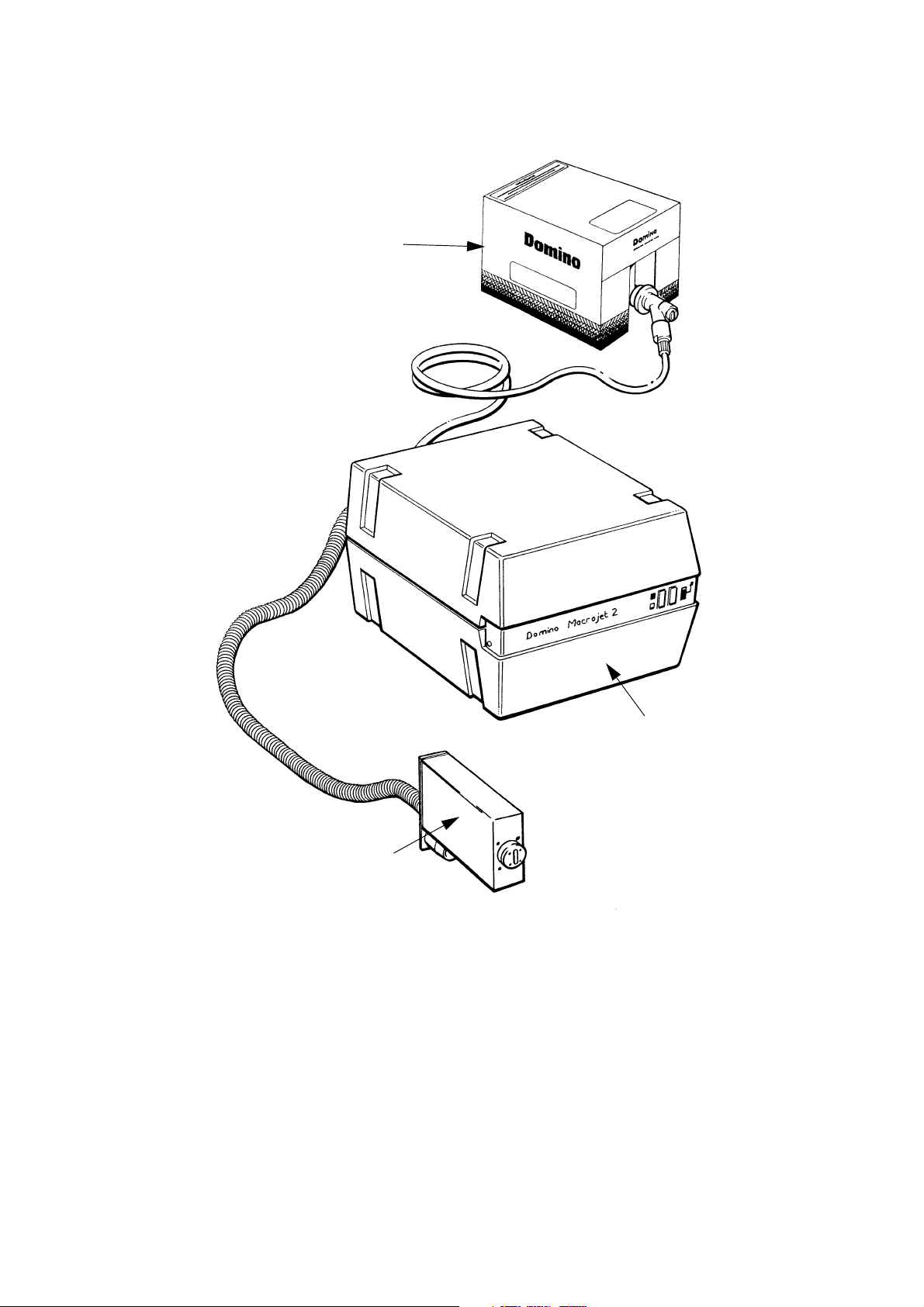
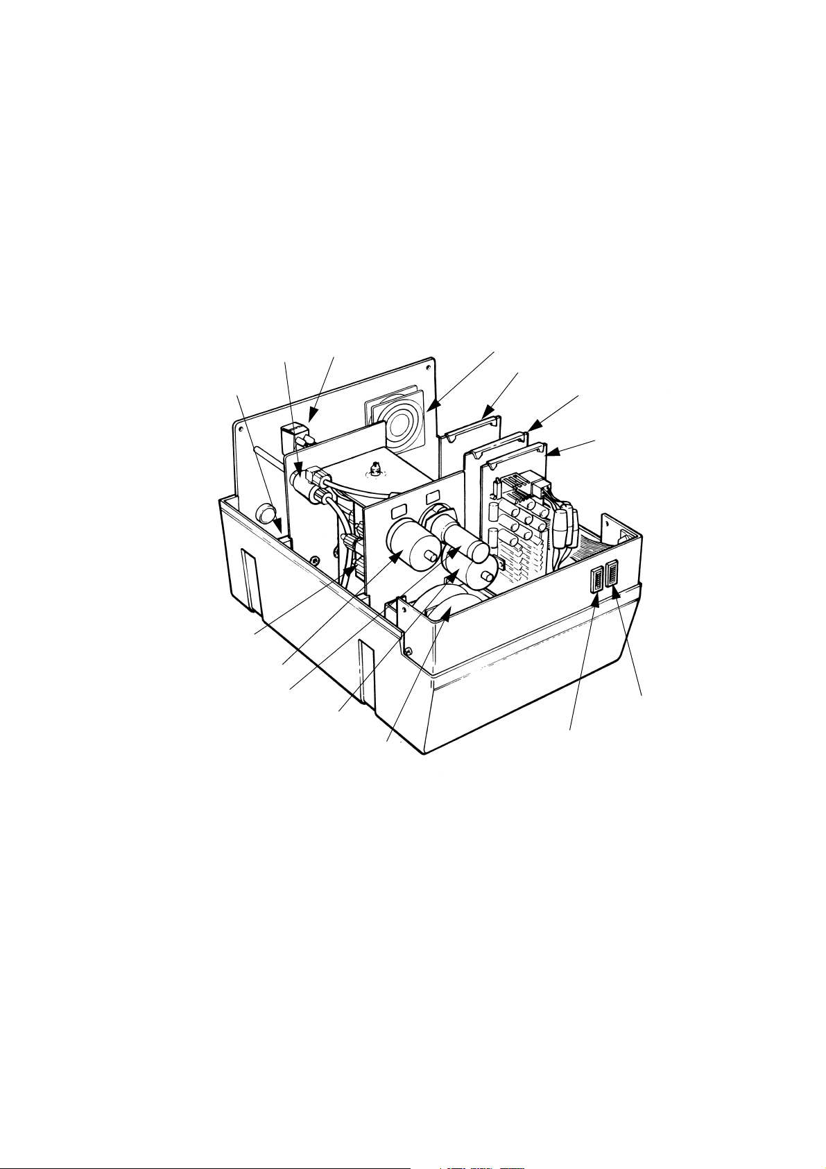
Macrojet 2 Large Character Printer
TP1006_1
Ink Box
Control Cabinet
Print Head
DESCRIPTION
20509 Issue 7 Jan 2018 2-3
Page 18

DESCRIPTION
INTRODUCTION
The Macrojet 2 large character printer consists of:
• The print head (up to four can be fitted to one cabinet)
• The control cabinet
• The product detector (one or two can be fitted)
• The disposable ink supply container.
Print messages are normally entered using a Domino Pocket Terminal.
Print heads can be supplied to print with either 7 or 16 ink drops and in a
range of character heights (see
assembly connected to the cabinet by a flexible conduit and will work in
any position. Print heads can be added or changed without difficulty.
The control cabinet contains an ink system supplying ink to the print
head(s) and an electronics control system. Controls and external
connections are grouped on a panel at the rear.
The product detector is mounted on the line and senses the product as it
approaches the print head. There are three optional types: two are infra-red
beams and a third works by metal detection.
page 2-7). Each is a separate stainless steel
Ink is supplied in a disposable 5 litre bag-in-box ink container, connected to
the printer by a Quick Connect/Disconnect (QCD) connector.
Messages to be printed are normally entered as serial digital data from a
Domino Pocket Terminal, but it is also possible to control the printer from a
separate computer system (details from Domino).
The printer contains a set of separate auxiliary alarm contacts which can be
connected to external indicators or other equipment. An optional alarm
beacon is also available to show the printer status.
Another option is a shaft encoder which allows the printer to follow line
speed variations. This includes the slowing down and speeding up
involved in line stop and start.
2-4 20509 Issue 7 Jan 2018
Page 19
DESCRIPTION
PRINTER SPECIFICATION
Print Heads
7 or 16 drop nozzle heads. Multiple heads in combinations of:
• Up to 4 heads each of 7 nozzle size, or
• Up to 2 heads each of 16 nozzle size, or
• 1 head of 16 nozzle size and 1 head of 7 nozzle size, or
• 1 head of 16 nozzle size and 2 heads of 7 nozzle size.
Print Characteristics:
Character set: 96 ASCII, printed as 7x5 or 16x10 matrix.
Character height: 8mm (5x5 matrix 12 and 32 only)
12, 16, 20, (7 x 5 matrix).
12mm Tray Coder
32mm (16 x 10 matrix)
or 2 lines 12mm (7x5 matrix).
50mm (16 x 10 matrix)
or 2 lines 20mm (7x5 matrix).
Maximum print speed: 100 metres/second at 12.5mm Character width ch
Messages: Up to 40 messages of up to 200 characters length
Cabinet
Dimensions: Width: 394mm (15.51")
Depth: 443mm (17.44")
Height: 282mm (11.1")
Weight: 24.5kg (54lb)
Print Heads
Spacing from print surface: 25mm max.
Conduit Length: 4m, 8m.
7 Nozzle Head:
Height: 85mm
Width: 70mm
Depth: 223mm (12, 16 and 20)
Depth: 278mm (low level 12mm)
16 Nozzle Head:
Height: 111mm
Width: 70mm
Depth: 269mm
20509 Issue 7 Jan 2018 2-5
Page 20

DESCRIPTION
Environment
Temperature Range
+5º to +40ºC (42ºF to 104ºF)
(Operating):
Humidity: 10 - 90% RH (non-condensing)
Electrical Requirements
Supply Voltage: 110V, 130V, 150V, 220V, 240V, 260V, single
phase with ground.
Power: 300VA
Supply frequency: 50/60Hz
Supply Fuse Rating
Power switch: 2A (220-260V)
4A (110 - 150V)
Inputs
Product Detector: 12V, 100mA dc supply to sensor, 5 pin AXR
connector.
Shaft Encoder (print rate
control):
Data Interface: RS232 or 20mA current loop
suitable for open collectors or TTL encoders.
Encoder power supply link selectable, +5V
or +12V. 5 pin AXR connector.
75-19,200 Baud, selectable.
External Alarms
One output via changeover
relay contacts:
2.5A at 260V max. Non inductive.
2-6 20509 Issue 7 Jan 2018
Page 21
DESCRIPTION
TP1290_1
PRINT HEAD
Ink jet printing does not require contact with the print surface. It is therefore
particularly suitable for printing on rough, irregular, soft or other "difficult"
surfaces.
Macrojet 2 is a valve jet printer. Ink is maintained under pressure behind a
closed nozzle or valve. When the valve is opened for a short time, ink
emerges as a drop and is propelled by the pressure towards the print
surface or substrate. Drops are, therefore, only produced as required in
what is known as Drop-on-Demand printing.
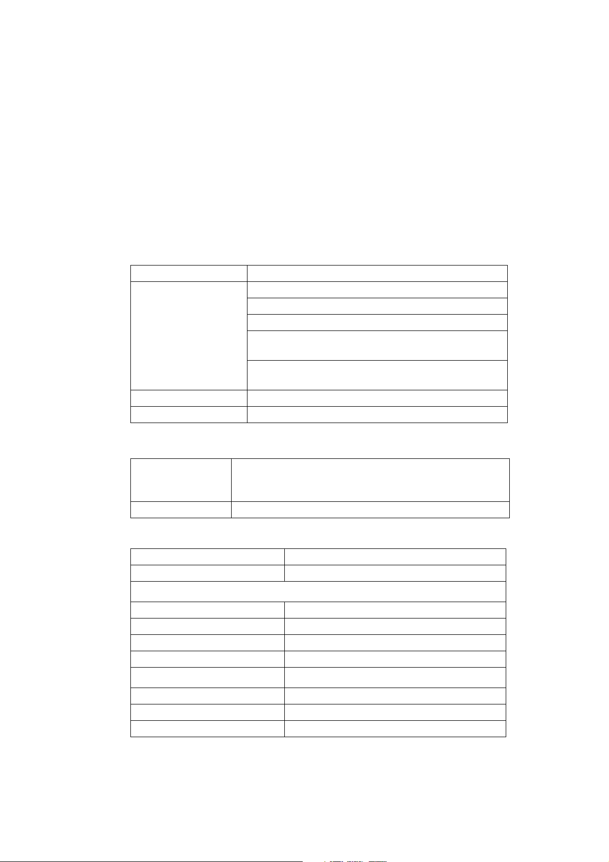
Macrojet 2 print heads have either 7 or 16 nozzles producing a line of drops
called a stroke on the print surface. As the print surface moves past the
head, successive strokes containing different combinations of ink drops
build up the character in the form of a dot matrix. This is best understood
by studying the illustration below.
A dot matrix is specified by the number of dots in a stroke and the number
of strokes making up a single character (for example, the illustration shows
a 7x5 matrix).
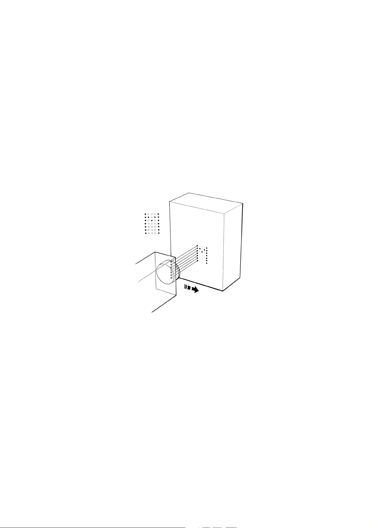
The Macrojet print head has, at the front, a nozzle plate with either 7 or 16
nozzles. Ink is supplied under pressure to a manifold behind the nozzle
plate. A plunger, fitted with a rubber slug on its tip, is held against each
nozzle by a spring. The plunger is connected by a wire to a metal slug
sitting part of the way into a solenoid. When the solenoid is energised, the
slug is pulled into the centre of the solenoid. This pulls back the plunger,
opening the nozzle. When the solenoid is de-energised, the spring pushes
the plunger back to close the nozzle.
20509 Issue 7 Jan 2018 2-7
Page 22
DESCRIPTION
TP1291_1
Plunger Slug Slug Return Spring Solenoid
Nozzle Plunger Control Wire Solenoid Slug
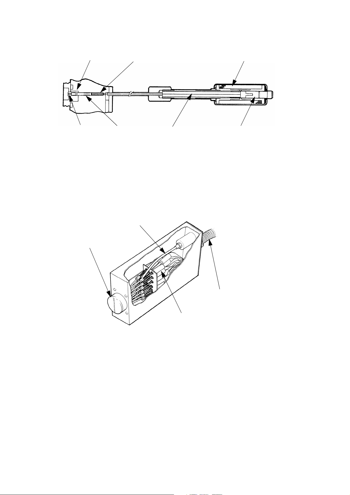
TP1380_1
Nozzle Plate
Feed Pipe
Solenoids
Conduit
The Print Head
The ink that emerges from the nozzle forms a drop, ejected onto the print
surface by the ink pressure. Drop size, density and quality of the print is
controlled by three factors:
• The time for which the solenoid is energized
• The position of the slug when the solenoid is de-energized
• The ink pressure.
Ink flow into the head can be shut off with the print head valve. A purge
switch operates all the nozzles to remove any air (see
The print head is mounted at right angles to the print surface, at a distance
of 3 to 5mm for best print quality. At distances outside these limits, print
quality will be reduced.
Macrojet 2 has a number of print head and print options. The print options
are shown in the diagrams (see
will print only the single line options. A 16 drop head is required to print the
page 2-9 and page 2-10). A 7 drop head
twinline and large options. Up to four lines of print (7x5), by way of four 7
drop heads or two 16 drop heads, can be supplied from a single control
cabinet
page 3-4).
2-8 20509 Issue 7 Jan 2018
Page 23
TP1410_1
Single line 7 x 5 matrix.
Standard Character Printing Styles
TP1412_1
TP1413_1
TP1414_1
Twin line 7 x 5 matrix.
Single line
16 x 10
matrix.
Single line 16 x
10 and 7 x 5
matrix (top or
bottom line).
DESCRIPTION
20509 Issue 7 Jan 2018 2-9
Page 24
TP1415_1
Single line 5 x 5 matrix.
Optional Character Printing Styles
TP1417_1
TP1418_1
TP1419_1
Twin line 5 x 5 matrix.
Single line 5
x 5 and 7 x 5
matrix.
Single line 16 x 10 with single
line 7 x 5 and single line 5 x 5
(top or bottom line)
DESCRIPTION
2-10 20509 Issue 7 Jan 2018
Page 25
DESCRIPTION
Control Cabinet
TP1039_3
Accumulator
Bleed
Valve
Pump
Switch
Inhibit
Fan
Solenoid Driver
Serial Interface
Board
Low Voltage
PSU
Power On
Indicator
Ink Container
Empty Indicator
Power Transformer
Vacuum Switch
Pump
Pressure Switch
Manifold
CONTROL CABINET
The control cabinet is moulded in a structural foam material which is
extremely strong, light and easy to clean. It is sprayed internally and
externally with epoxy paint. A special coating providing RF shielding is also
applied to the internal surfaces.
The cabinet consists of a base, holding the ink and electronics systems,
and a cover fitted over the top. A panel carrying the controls and
connectors is fitted into the rear of the cabinet. The panel is also fitted with
a fan that prevents an accumulation of fumes in the cabinet. The air is
exhausted out of holes in the base under the transformer.
The ink and electronics systems occupy separate halves of the base and a
bulkhead formed in the cover drops between them. Removing four screws
and lifting the cover provides access to the whole cabinet.
20509 Issue 7 Jan 2018 2-11
Page 26
DESCRIPTION
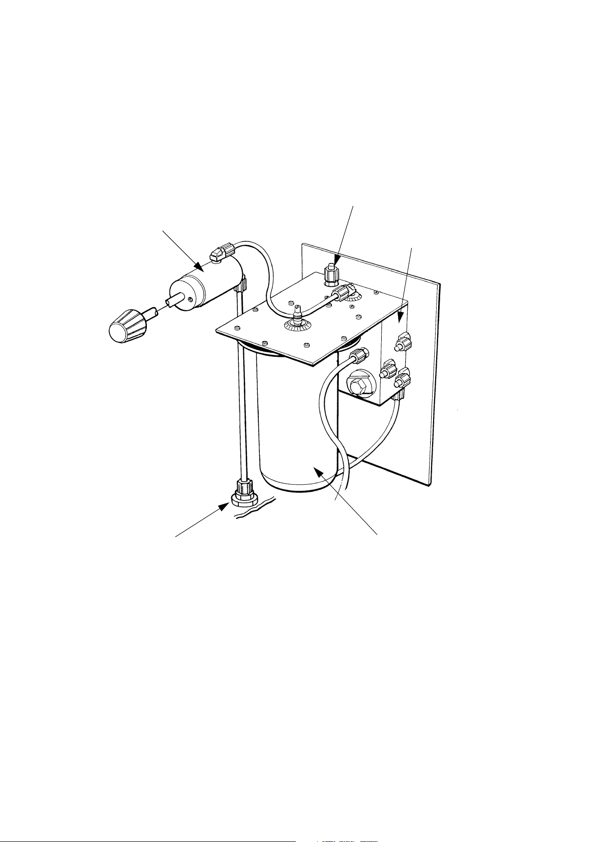
Ink System Components
TP1385_2
Vent
Bleed Valve
Priming Port
Ink Manifold
Accumulator
INK SYSTEM
General
The ink system draws in ink from the ink supply container and supplies it
under pressure to the print head. The system is governed by switches
which control the ink pressure and detect when the ink container is empty.
2-12 20509 Issue 7 Jan 2018
Page 27

Ink System Diagram
M
Accumulator
Bleed
Valve
Vent
Print Head
Valve
Print Head
Main Cabinet
Ink
Container
QCD
Connector
Vacuum Switch
Filter
Spring
NRV
Print Head
Manifold
Solenoids
Pressure Switch
Choke
Bleed
Reservoir
NRV
DESCRIPTION
20509 Issue 7 Jan 2018 2-13
Page 28

DESCRIPTION
INK SYSTEM
The ink system is shown schematically in the diagram opposite. Fresh ink
is contained in a 5 litre disposable ink container, which consists of a flexible
bag protected by a robust cardboard box. The ink container is connected
using a special quick QCD connector.
A gear pump draws ink into the system through a 20 micron filter and spring
Non-Return Valve (NRV) and pumps it into the bleed reservoir. Residual air
collects in the reservoir and opening the bleed valve allows this air to
escape through the vent in the cabinet floor. A by-pass loop, containing a
choke to reduce the flow rate, is connected from the bleed reservoir to the
inlet side of the gear pump. This ensures that the pump remains primed if
air is drawn in through the ink feed pipe.
Ink from the bleed reservoir is forced through a plain NRV into the
accumulator which holds the working reservoir of ink for the print heads.
The accumulator has a flexible diaphragm clamped between the
accumulator body and the mounting flange on the steel frame. The
diaphragm is shaped to contain a volume of air. The mounting flange is
sealed and the only access into the diaphragm is an air valve provided for
maintenance purposes.
As ink is pumped into the accumulator it compresses the air sealed inside
the diaphragm. When the ink is pressurised to 7psi (0.48 Bar) the pressure
switch trips and switches the pump off. The plain NRV closes to maintain
the pressure in the accumulator and re-opens only when the pump next
runs. As ink from the accumulator is used up in printing, the pressure
drops. At approximately 5psi (0.35 Bar) the pressure switch resets,
switching on the pump. The accumulator has a capacity of approximately
70ml, provided by compressing the air behind the diaphragm.
Pressurised ink is fed from the accumulator, through the print head hand
valve and the conduit feed pipe, to the print head manifold behind the
nozzle plate.
When the pump is running and the ink supply container becomes empty, a
vacuum is generated in the feed line. At 8 - 10 inches of mercury (2.76 -
3.45 kilogrammes per sq cm) the vacuum switch trips, switching off the
pump and lighting the Ink Container Empty indicator. The spring NRV shuts
off, and maintains the vacuum.
2-14 20509 Issue 7 Jan 2018
Page 29
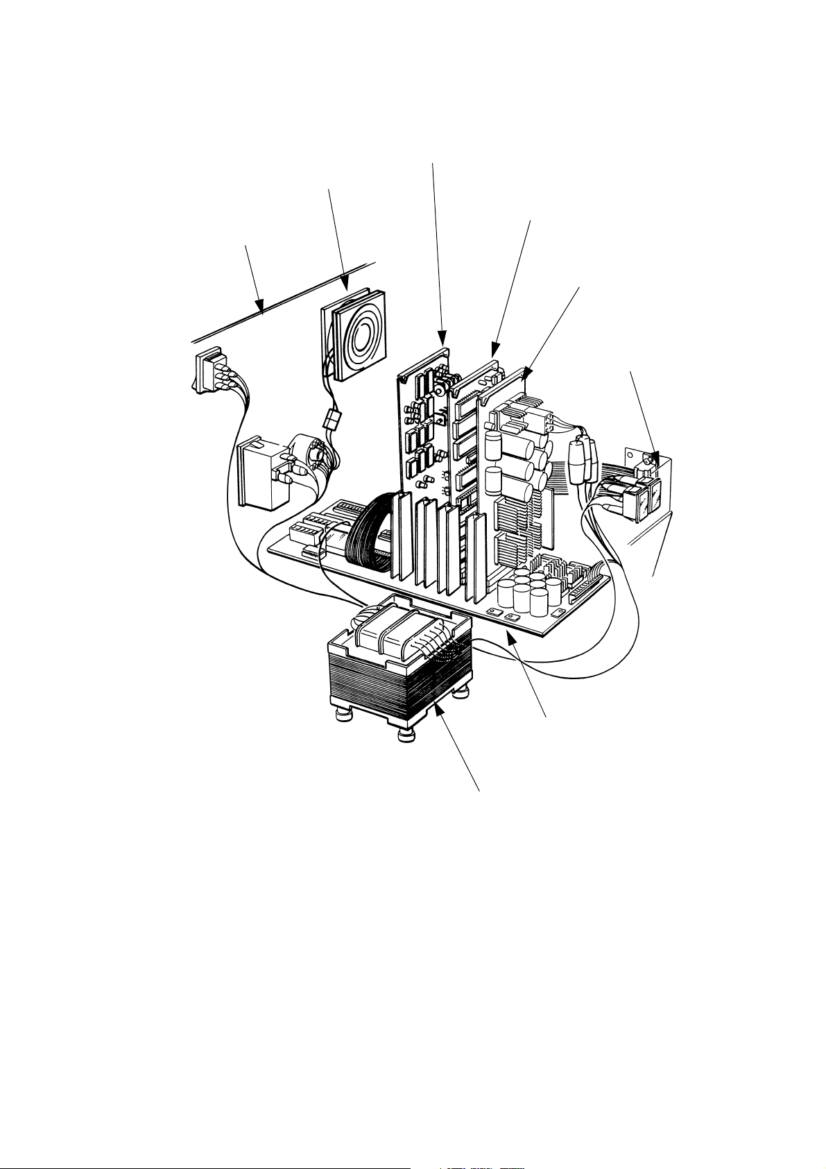
Electronics Components
TP1390_2
Power Transformer
Motherboard
Front Panel
Assembly
Low Voltage
Power Supply
PCB
Universal Serial
Interface PCB
Solenoid Driver
PCB
Fan
Rear Panel
Assembly
DESCRIPTION
20509 Issue 7 Jan 2018 2-15
Page 30

DESCRIPTION
ELECTRONIC SYSTEM
General
The electronic system contains a microprocessor, which controls the
message data input, processing and printing. It also contains circuits to
drive the solenoids in the print head and to generate d.c. power supplies.
The system consists of the following Printed Circuit Boards (PCBs):
• Universal Serial Interface
• Solenoid Driver (one or two depending on the number of print heads)
•Low Voltage Power Supply
• Motherboard.
The motherboard lies flat in the base moulding. The PCBs are plugged
vertically into it and are held in place by a foam strip in the top cover. A
single power transformer provides the low voltages required by the power
supply circuits.
The product detector is part of the electronics system. It detects the
product as it approaches the print head and provides a Print Go signal to
the printer. Macrojet 2 is able to use two detectors, with assignment of
print heads to detectors being set up with the Pocket Terminal. For details
see Pocket Terminal User's Guide, Part Number 20524.
Having been detected, the product still needs time to pass under the head
and reach the correct position for printing. The electronics system allows
for this with the Print Go delay, which is also set up using the Pocket
Term in al .
A shaft encoder is an option which enables the printer to follow line speed
variations. It has been explained how characters are printed by strokes, as
the product passes the head. If the stroke rate is fixed and the product
speed changes, the strokes will become closer or further apart. The result
is a change in the character shape. The Print Go delay is also measured in
strokes and a fixed stroke rate gives a fixed delay. Changes in the product
speed will, result in a change in the position of the printed message.
A shaft encoder is attached to the line and follows the line speed. Using it
to control the stroke rate eliminates the variations in character shape and
message position.
2-16 20509 Issue 7 Jan 2018
Page 31

DESCRIPTION
Controls and Indicators
TP0150_1
Power On
Indicator
Ink Container
Empty Indicator
Character Width
Control
Fan
Intensity
Control
External
Connection
Cable Glands
Pump Inhibi t
Switch
Ink System
Bleed Valve
Product
Detector
Inputs
Shaft
Encoder
Input
Voltage
Selector
Power On/
Off Switch
Print Head
Conduit
Holes
TP0151_1
2A (220 - 260V)
4A (110 - 150V)
2A
4A
Controls and Indicators
Controls and indicators are shown in the diagram below. The supply power
on/off switch also contains a fuse (see
the printer together with any equipment connected to the Auxiliary Power
connector block. The voltage selector switch must be set to the nearest
value to the input supply.
page 4-30) which is rated to support
The pump maintaining ink pressure is controlled by the ink pressure switch.
The pump therefore only operates intermittently. It may be necessary to
ensure that the pump does not operate at all (for example, during
maintenance). The rear panel therefore carries a Pump Inhibit switch,
containing an indicator which goes out when the switch is inhibiting the
pump and the printer is not completely ready for use.
20509 Issue 7 Jan 2018 2-17
Page 32

DESCRIPTION
Universal Serial Interface PCB
The Universal Serial Interface PCB contains a microprocessor which
controls both data input and printing routines. It receives input data in the
form of serial characters and control codes, and converts it into dot matrix
patterns for output to the Solenoid Driver PCB. Characters to be printed
are converted into dot matrix form by character set look up tables
contained in Electronically Programmable Read Only Memories (EPROMs).
Print commands such as bold or reversed are stored in the Random Access
Memories (RAM) along with the dot matrix for that character.
The Universal Serial Interface PCB contains circuits for the RS232 interface,
real time clock, stroke generator, product detector inputs and printed stroke
output. When Macrojet 2 is powered down, a battery backup automatically
maintains the RAM and clock in standby.
This PCB has links and switches that need to be set up to match the printer
system and application (see
page 4-31 and page A-8).
Solenoid Driver PCB
This PCB accepts parallel dot matrix information and amplifies it into
signals suitable to drive the print head solenoids. Each solenoid driver PCB
can drive up to sixteen solenoids. The PCB is arranged as two identical
channels of eight lines. The channels can run independently and drive one
or two 7 drop heads. Alternatively, the two channels can drive one 16 drop
head. Selector links allow one intensity control to govern all sixteen
nozzles. Data is input to the board in 8-bit patterns. With a 16 drop head,
the first 8- bit pattern controls the upper eight nozzles.
Low Voltage Power Supply PCB
This PCB assembly provides the +5V, +12V regulated and +10V
unregulated supplies to the electronics system. The +5V supply powers all
the logic and microprocessor circuits. The +12V supply is used to power
the RS232 circuits, the stroke generator, product detector and the shaft
encoder. The +10V unregulated supply is used to charge the Universal
Serial Interface PCB battery. It is also used to power the power fail detect
circuit which detects the onset of a power failure.
2-18 20509 Issue 7 Jan 2018
Page 33

The Electronic Control System
Universal Serial Interface PCB
Character
Width
Control
Shaft
Encoder
(Optional)
Product
Detector
Pocket
Termi na l
Stroke
Generator
Micro
Processor
Memory
Battery
Backup
Real Time
Clock
Input/
Output
Latch
Solenoid
Driver Pulse
Generator
Store
Gate
Gate
Solenoid
Solenoid
Solenoids
Solenoids
Low Voltage Power Supply PCB
+5V
+12V
+10V
External
Alarms
Intensity
Control
DESCRIPTION
20509 Issue 7 Jan 2018 2-19
Page 34

DESCRIPTION
Motherboard
The motherboard provides the interconnections between the PCBs in the
control system. It also carries all the input/output connections for the print
heads, data input, product detector, vacuum switch and external alarm
relay. The connections for one print head are all contained in a single "D"
connector. There are, therefore, four of these connectors on the
motherboard. Associated with each connector is a dual-in-line (DIL) switch
controlling the aspect ratio of the characters printed by the head.
Four rectifier/capacitor circuits on the motherboard, supplied from windings
on the power transformer, provide the 24V power supplies for the solenoid
drivers.
The motherboard has connections and switches that need to be set up to
match the printer system and application (see
page 4-38 and page A-8).
Product Detector
With a fixed product speed past the print head, the Macrojet 2 may be set
up to use a fixed print speed and operate with one of the following types of
detector:
• Photocell Detector (Reflective)
• Photocell Detector (Proximity)
• Inductive Proximity Detector.
Photocell detector (Reflective) uses a reflector mounted on the opposite
side of the product line. A light beam from the detector is returned by the
reflector to the photocell in the detector. The control circuits detect when
the reflected beam is broken (or restored after interruption) and generates
the print go signal. A time delay will normally still exist between detection
of the product and its arrival in the exact position required for printing. A
compensating delay is, therefore, entered as part of the input print data.
Photocell Detector (Proximity) does not use a reflector. Product detection
depends on reflection from the body of the product or when the edges of
light or dark markings on the product are detected.
The proximity detector senses metal products when they come within
range. This detector normally requires to be very close to the product. The
exact distance is usually dependent upon the material from which the
product is made.
The product detector must be positioned "up-stream" from the print head.
A time delay is necessary to allow the product to reach the print head and
the printing to be placed correctly. This is set up in the printer as the print
go delay (part of the Pocket Terminal input data).
Shaft Encoder (Optional)
With a fixed print speed, if the line speeds up, the printing will be spaced
further apart. If the line slows down, the printing will close up. This
problem is avoided by fitting a shaft encoder.
2-20 20509 Issue 7 Jan 2018
Page 35

DESCRIPTION
The shaft encoder is attached to the product line and produces electrical
pulses as it revolves. There are a fixed number of pulses to each revolution.
The printer is set up so that character stroke rate or print speed is
controlled by these pulses instead of by the internal character width control
(see LK6 on
page 4-35). As the line speeds up or slows down, the shaft
encoder pulses change speed and change the speed of printing.
The exact type of shaft encoder depends upon the installation and more
details of the factors to be considered are given in Appendix A.
20509 Issue 7 Jan 2018 2-21
Page 36

DESCRIPTION
EXTERNAL CONNECTIONS
Product Detector and Shaft Encoder Connectors
(5-pin AXR)
There are three connectors SK1, SK2 and SK3. Connectors SK1 and SK3
are wired with the same connections so that a product detector can be
connected into either connector and a shaft encoder connected into the
other. Alternatively, SK1 and SK3 can be used to loop a single product
detector to another Macrojet 2 in an extended system. Where a second
product detector is used this must be connected into SK2. Pin connections
are given below:
SK1 SK2 SK3 Signal
1 1 1 0V
2 2 2 Shaft Encoder
3 - 3 Print Go 1
- 3 - Print Go 2
4 4 4 +5V
5 5 5 +12V
Product Detector and Shaft Encoder Connections
Power Connector
Euroconnector with moulded lead:
•Line - brown
• Neutral - blue
• Ground - yellow/green.
Macrojet 2 must be connected to earth (ground).
2-22 20509 Issue 7 Jan 2018
Page 37

DESCRIPTION
Pocket Terminal Connector (Data Entry 25-way
D Connector)
PIN SIGNAL PIN SIGNAL
1 0V 12 Tx +ve
2 RS232 Data In 13 Rx +ve
3 RS232 Data Out 18 -12V
4 CTS (Input) 21 20mA ENABLE
5 RTS (Output) 22 +12V
7 0V 24 Tx -ve
9 +5V 25 Rx -ve
11 20mA Source
Data Input Pin Connections
For RS232 operation, pins 13 and 24 are linked to disable the 20mA loop.
Pins 4 and 9 may also be linked to set CTS. For 20mA loop operation, pins
21 and 22 are linked. The terminal as supplied has the connections set for
RS232 operation.
Data must be fed from the external source while the machine is being set
up or during non-print periods.
External Alarms
The printer has a set of changeover relay contacts which are operated at
the same time as the printer fault lamp. However, they are completely
separate from the printer circuits and are provided for external use. Wiring
to the contacts enters the cabinet through one of the cable glands and
goes to the motherboard.
The connections are:
• PL5/1 and PL5/2 (printer internal contacts normally open)
• PL5/1 and PL5/3 (printer internal contacts normally closed).
20509 Issue 7 Jan 2018 2-23
Page 38

DESCRIPTION
THIS PAGE INTENTIONALLY LEFT BLANK
2-24 20509 Issue 7 Jan 2018
Page 39

MAINTENANCE PROCEDURES
PART 3 : MAINTENANCE
PROCEDURES
CONTENTS
Routine Maintenance ............................................................................ 3-3
Cleaning the Nozzle Plate ................................................................ 3-3
Purging the Print Head ..................................................................... 3-4
Bleeding the Ink System .................................................................. 3-5
2000HR Maintenance ........................................................................... 3-6
Access to the Cabinet and Print Heads ........................................... 3-6
Ink Filter Replacement ..................................................................... 3-6
Checking Drop Size ......................................................................... 3-9
Adjusting Drop Size ......................................................................... 3-9
Fan and Filter Check ........................................................................ 3-10
Changing Inks ....................................................................................... 3-11
Changing to New Ink with same Solvent Base ................................ 3-11
Changing to New Ink with different Solvent Base ........................... 3-13
Page
20509 Issue 7 Jan 2018 3-1
Page 40

MAINTENANCE PROCEDURES
THIS PAGE INTENTIONALLY LEFT BLANK
3-2 20509 Issue 7 Jan 2018
Page 41

MAINTENANCE PROCEDURES
ROUTINE MAINTENANCE
WARNINGS: (1) When working on or near the ink system,
protective clothing (especially safety glasses)
must be worn.
(2) Power to the printer must be removed before
carrying out any maintenance.
The main requirement is cleanliness. Keep Macrojet 2 clean and it will give
little trouble. The following procedures will make sure that print quality
does not deteriorate.
CAUTION: The ink system vent is on the underside of the
printer cabinet. Clean away any ink deposits which
may occur under the cabinet.
Cleaning the Nozzle Plate
CAUTION: Some wash solutions can damage the electronic
components inside the print head. The following
methods must be used to avoid any damage.
The nozzles must be washed and dried carefully before start-up and after
shut-down. Make sure the correct wash solution is used and always wipe
with lint-free tissue.
If only light cleaning is necessary, or the print head cannot be dismounted,
clean the nozzle plate with tissue moistened with wash solution.
For thorough cleaning:
(1) Remove the print head from its mounting.
(2) Hold the print head vertically with the nozzle plate at the bottom,
facing downwards.
(3) Using a wash bottle, flush the nozzle plate with wash solution. Pay
particular attention to the nozzles and minimise spraying solution
where it can penetrate into the head.
(4) Wipe away all wash solution while the print head is still vertical.
(5) Inspect the nozzle plate. If it is not entirely clean repeat the cleaning
process (steps (2) - (4)) with the nozzle plate facing downwards as
before.
(6) Refit the print head into its operation position.
Note: If a nozzle becomes blocked, partially or completely, purge the
print head (see
page 3-4).
20509 Issue 7 Jan 2018 3-3
Page 42

MAINTENANCE PROCEDURES
Purge
Switch
TP2105-1
Purging the Print Head
The purge switch on the print head operates all solenoids continuously, to
sweep out traces of air and dirt.
Move a piece of card across the nozzle plate, at the same time operate the
purge switch.
Check the dots printed on the card. They must show that all nozzles are
producing drops of ink correctly.
If purging does not clear all nozzles, the nozzle assembly must be removed
and cleaned in an ultrasonic bath (see
page 4-9).
3-4 20509 Issue 7 Jan 2018
Page 43

MAINTENANCE PROCEDURES
Pump Inhibit
Switch
Bleed Valve
Bleeding the Ink System
At regular intervals, normally once a day, the ink system must be bled to
prevent the build up of air in the system.
(1) Set the Pump Inhibit switch on the rear panel to position 0.
Note: The light in the switch will extinguish.
(2) Slowly open the bleed valve on the rear panel by turning the knob
counter-clockwise. Use a piece of tissue to catch any ink escaping
from the vent in the underside of the printer cabinet.
(3) Wait for 10 seconds and close the valve.
(4) Set the Pump Inhibit switch to position 1.
20509 Issue 7 Jan 2018 3-5
Page 44

MAINTENANCE PROCEDURES
Securing
Screws
TP2105-1
2000HR MAINTENANCE
Access to the Cabinet and Print Heads
The cabinet cover is lifted off after removing the four securing screws.
Note: The cover has a ground wire connected by a snap connector.
Make sure this wire is connected whenever replacing the cover.
The cover on the print head is removed by sliding forward over the nozzle
plate after removing the four securing screws at the front and rear of the
print head. When replacing the cover, make sure that the "O" ring round
the nozzle plate is correctly fitted.
Ink Filter Replacement
The ink filter is fitted into the manifold block. It must be replaced every
2000 hours or every six months, whichever comes first.
The printer must be switched off at the power switch and the cabinet cover
removed. Pull out the electronic circuit PCBs and lay safely to one side,
then proceed as follows:
(1) Disconnect the QCD from the ink supply container.
(2) Close the valve on the print head by turning the knob fully clockwise.
(3) Place a container under the print head and carefully release the
screws fixing the nozzle plate just sufficiently for ink to escape.
(4) Slowly open the print head valve and allow ink to escape into the
container.
3-6 20509 Issue 7 Jan 2018
Page 45

Gasket
TP2104-1
Cover
Securing
Screws
Connector
O-Ring
Spring
Diaphragm
End Cap
O-Rings
TP3395-2
MAINTENANCE PROCEDURES
20509 Issue 7 Jan 2018 3-7
Page 46

MAINTENANCE PROCEDURES
(5) Continue to allow ink to escape until the ink system pressure has
fallen to zero. Leave the print head valve fully open.
(6) Place tissue in the cabinet base to catch any escaping ink.
(7) Unscrew the filter end cap.
(8) Remove the outer and inner O-Rings and the filter.
(9) Discard the O-Rings and filter. Wash out the filter recess and clean
the filter end plug.
To fit the new filter:
(10) Fit a new filter disc into the manifold block with the sharp edge of the
disc facing inward.
(11) Fit a new inner O-Ring onto the end cap.
(12) Fit a new outer O-Ring into the groove in the manifold block.
(13) Refit the filter end cap and tighten.
(14) Carefully refit the PCBs into their correct positions.
(15) Reconnect the QCD to the ink supply container
(16) Switch on the printer.
(17) Check the system for leaks. If everything is satisfactory, switch off
the printer and replace the print head and cabinet covers.
3-8 20509 Issue 7 Jan 2018
Page 47

MAINTENANCE PROCEDURES
Dot
Diameter
TP2103-1
Purge
Switch
Checking Drop Size
All dots printed by a print head must be the same diameter. The diameter
must be 2.5 to 3.0mm for 12, 16, 20, 32 & 50mm heads.
(1) Remove, clean and replace the nozzle plate (see page 4-9).
(2) Switch on the printer and turn the intensity control to maximum (fully
clockwise).
(3) Move a piece of card at a constant speed across the front of the print
head at a distance of 8 - 10mm. At the same time operate the purge
switch.
(4) With a little practice it will be possible to print a series of separate
strokes on the card.
(5) Inspect the strokes printed on the card. All strokes must be made up
of dots of the same diameter. The dot diameter must be within the
dimensions given above.
Note: If the dots are not uniform and the correct diameter, it will be
necessary to adjust the solenoids to change the size of the ink
drops (see below).
Adjusting Drop Size
All nozzles must produce drops of the same size. They are made to do so
by adjusting the solenoids.
The printer must be switched on and working correctly in all other respects.
It will be necessary to work inside the print head and to print on a moving
test surface at the correct distance. If necessary, fit the print head onto a
test mounting to do this.
20509 Issue 7 Jan 2018 3-9
Page 48

MAINTENANCE PROCEDURES
Filter Cover
TP2050-2
Filter
Air
Flow
Air Flow Check
(1) Remove the print head cover.
(2) Turn the intensity control to maximum (fully clockwise). Perform a
drop size check to obtain a print sample.
(3) Check the printed dots and identify the solenoids that need adjusting.
(4) Loosen the locknuts which secure these solenoids.
(5) Adjust the solenoids counter-clockwise to increase dot size or
clockwise to reduce dot size.
(6) Check and adjust until the dots are correct.
(7) Re-tighten the locknuts and replace the print head cover.
(8) Set the intensity control to mid-position and repeat the drop size test
procedure. Check that the drops all remain uniform in size.
Fan and Filter Check
Switch on the printer and check that the fan starts and runs freely.
Switch off the printer, unclip the filter cover and remove the filter. Clean the
filter using warm, soapy water and dry thoroughly. Replace the filter if it is
badly clogged or damaged. If the filter is very dirty after 2000 hours, reduce
the interval between checks.
3-10 20509 Issue 7 Jan 2018
Page 49

MAINTENANCE PROCEDURES
TP2098-1
CHANGING INKS
Changing to New Ink with same Solvent Base
The procedure is to flush the printer with solvent appropriate to the ink type
in use, then to connect an ink supply container with the new ink and bleed
all the heads until the new ink flows through.
20509 Issue 7 Jan 2018 3-11
Page 50

MAINTENANCE PROCEDURES
Note: This procedure assumes the printer has more than one print
head. If only one head is fitted, the basic procedure is the same.
Flushing Procedure.
(1) Disconnect the QCD from the ink supply container.
(2) Make sure that the Pump Inhibit switch is set to 0 (Inhibit).
(3) Close the valve on each print head and remove the heads from their
mountings.
(4) Place all the print heads with their nozzles over a suitable container.
(5) Loosen each nozzle plate sufficiently for ink to escape.
(6) Open the valve on one print head and allow the contents of the ink
system to drain into the beaker.
(7) Close the valve.
(8) Remove the QCD from the feed pipe. Immerse the free end of the
pipe in a container containing several litres of the solvent appropriate
to the ink type currently used in the machine. Do not allow this
container to run dry.
(9) Set the Pump Inhibit switch to position 1 to allow the pump to
pressurise the ink system. When the pump stops, set the switch to
position 0. The ink system will now be full of solvent.
(10) Open the valve in the first print head and allow the solvent in the
system to drain from the nozzle plate.
(11) Close the valve.
(12) Repeat steps (9) to (11), draining the ink out through the next print
head. Repeat this until the ink system has been flushed five times
and each head at least three times.
(13) Refit the QCD to the feed pipe and connect a new colour ink
container.
(14) Bleed all the heads (see page 4-8) until the new ink emerges.
(15) Make sure the nozzle plates are secure. The printer can now be used
to print the new colour.
3-12 20509 Issue 7 Jan 2018
Page 51

MAINTENANCE PROCEDURES
Changing to New Ink with different Solvent Base
CAUTIONS: (1) If MEK base ink is to be changed to water base ink,
the ink system must be meticulously flushed to
prevent ink contamination. Extreme care must be
taken to remove all traces of the old ink. In older
printers it may be necessary to replace some pipes
to thoroughly remove the ink.
(2) Changing from water base ink to MEK base ink is
not possible without extensive replacement of ink
system components.
To change inks from one solvent base to another, flush first with the solvent
for the ink in the printer, then flush with the solvent for the replacement ink.
If the change is from MEK base to water base, ethanol solvent must be
used as an intermediate step. The ink base changes and the solvents used
in the flushing sequence are given in the table.
(1) Flush the ink system following steps (1) to (12) in the procedure given
above (page 3-12), using solvent with the same base as the ink in the
printer (First Flushing Sequence - see table below).
(2) Clean the container - see step (8) - and change the solvent to the
type given in the Second Flushing Sequence column in the table
below.
(3) Repeat steps (9) to (15) of the procedure given above.
Change
From
Change To
1st Flush
Sequence
2nd Flush
Sequence
6000 1100 6000 1100
1100 6000 1100 6000
1100 1000 1100 1000
1000 1100 1000 1100
KEY: 6000 Wash, Water (Old No: Type F)
1100 Wash, Alcohol (Old No: Type K)
1000 Wash, MEK (Old No: Type A)
Flushing Procedures
20509 Issue 7 Jan 2018 3-13
Page 52

MAINTENANCE PROCEDURES
THIS PAGE INTENTIONALLY LEFT BLANK
3-14 20509 Issue 7 Jan 2018
Page 53

FAULT FINDING AND REPAIR
PART 4 : FAULT FINDING AND REPAIR
CONTENTS
Introduction .......................................................................................... 4-2
Faults Related to the Ink System .......................................................... 4-2
Faults Related to the Print Head .......................................................... 4-4
Faults Related to the Electronic System .............................................. 4-5
User Related Faults .............................................................................. 4-5
Print Quality Faults ............................................................................... 4-6
Print Head ............................................................................................. 4-8
Bleeding the Print Head ................................................................... 4-8
Removing the Nozzle Plate .............................................................. 4-9
Testing a Solenoid ........................................................................... 4-10
Replacing a Solenoid ....................................................................... 4-11
Print Head Plunger Slug Replacement ............................................ 4-11
Replacing a Print Head .................................................................... 4-15
Ink System ............................................................................................ 4-16
Depressurising the Ink System ........................................................ 4-16
Pressurising the Ink System ............................................................ 4-17
Priming the Ink System .................................................................... 4-17
Filter and NRV Leaks ....................................................................... 4-19
Refurbishing a Spring NRV .............................................................. 4-19
Refurbishing a Plain NRV ................................................................. 4-20
Pressure Switch Replacement ......................................................... 4-21
Vacuum Switch Check ..................................................................... 4-23
Vacuum Switch Replacement .......................................................... 4-24
Pump Replacement ......................................................................... 4-25
Accumulator Check ......................................................................... 4-26
Reinflating the Accumulator Diaphragm .......................................... 4-26
Refurbishing the Accumulator ......................................................... 4-28
Removing the Ink System ................................................................ 4-29
Electronic System ................................................................................. 4-30
Fuse Replacement ........................................................................... 4-30
PCB Replacement ........................................................................... 4-30
Replacing the Universal Serial Interface PCB .................................. 4-31
Minimum Width Adjustment ............................................................. 4-36
Replacing a Solenoid Driver PCB .................................................... 4-37
Replacing the Low Voltage Power Supply PCB .............................. 4-37
Replacing the Motherboard ............................................................. 4-38
Fan or Filter Replacement ................................................................ 4-39
Cabinet Wiring Component Replacement ....................................... 4-40
Page
20509 Issue 7 Jan 2018 4-1
Page 54

FAULT FINDING AND REPAIR
INTRODUCTION
WARNING: Protective clothing, especially eye protection,
should be worn at all times when working on the
ink circuit.
This part of the manual provides help in identifying the causes of problems
and gives repair procedures. Certain repairs should only be carried out by
trained personnel, and it is recommended that the printer or sub-assembly
is returned to Domino or a distributor.
FAULTS RELATED TO THE INK SYSTEM
Indication Possible Cause Remedy
Ink pressure
reduced
(* See Note)
Pressure drops
when bleed valve
opened
Pump runs
intermittently
during normal
pressurisation
Back leakage through
NRVs
Pressure switch leak Check connections and
Air leak at manifold Tighten all external
Air leak at accumulator
valve, elbow fitting,
flange or valve boss
weld
Back leakage through
accumulator NRV
Restriction in inlet pipe
from ink container
Ink filter blocked Replace ink filter. (see
Check NRVs and clean
as necessary. (see page
4-19)
replace if necessary. (see
page 4-21)
elbow fittings and check
piping. If fault persists
replace ink system
Check tightness of
fittings. If fault persists
replace ink system
Check tightness of
fitting. Strip and clean
where necessary. (see
page 4-21)
Check condition of inlet
pipe from ink container
page 3-6)
* Note: Ambient temperature drop will cause an apparent loss in
pressure. This is normal.
4-2 20509 Issue 7 Jan 2018
Page 55

FAULT FINDING AND REPAIR
Indication Possible Cause Remedy
Pump runs
intermittently with
ink container
empty
Pump runs but
does not
pressurise
system
Pump runs
continuously
Air leak in inlet line at ink
container fitting
Check condition of ink
container QCD and feed
line
Air leak at inlet filter Check tightness of
fittings
Back leakage through
spring NRV O-Rings
Check condition of NRV.
Strip and clean where
necessary. (see page -
19)
Excess air in bleed
reservoir
Bleed air from ink
system. (see page 3-5)
Air leak in system Check tightness of all
connections and fittings.
If fault persists replace
ink system
Faulty pump Replace pump. (see
page 4-25)
Back leakage through
NRVs
Strip and clean NRVs
(see page 4-19)
Ink leakage Check tightness of all
fittings
Faulty pressure switch Check pressure switch.
Replace if fault persists,
page 4-21)
(see
Air leak at accumulator Check tightness of all
fittings. If fault persists,
replace ink system.
20509 Issue 7 Jan 2018 4-3
Page 56

FAULT FINDING AND REPAIR
FAULTS RELATED TO THE PRINT HEAD
Indication Possible Cause Remedy
One or more
nozzles not
working (new
head)
One or more
nozzles not
working (head
previously OK)
One or more
drops cannot be
adjusted large
enough
Dirty nozzles Clean nozzles. (see page
3-3)
Stuck plunger Check condition of
plunger and replace slug
if necessary. (see
page
4-11)
Solenoid has weak pull Check condition and
replace if necessary. (see
page 4-11)
Bad electrical
connection
Check wiring in print
head
Air in print head Bleed print head. (see
page 4-8)
Blocked nozzles Clean nozzles. (see page
3-3)
Solenoid adjustment
incorrect
Rubber plunger slug
damaged
Adjust solenoid. (see
page 3-9)
Replace plunger slug.
(see page 4-11)
Partially blocked nozzle Clean nozzles. (see page
3-3)
Solenoid has weak pull Check condition and
replace if necessary. (see
page 4-11)
One or more
drops misaligned
Partially blocked nozzle Clean nozzles. (see page
3-3)
on printed output
Nozzle jewel misaligned Replace nozzle plate.
page 4-9)
(see
Solenoid driver PCB fault Replace Solenoid driver
PCB. (see page 4-37)
Ink pressure too low Check ink pressure. (see
page 4-21, step 8)
Abnormally large
drops
4-4 20509 Issue 7 Jan 2018
Leaks on air side of
accumulator
See page 4-26.
Page 57

FAULT FINDING AND REPAIR
FAULTS RELATED TO THE ELECTRONIC
SYSTEM
Indication Possible Cause Remedy
Fuse blows
repeatedly
Encoder not
working
Machine stops
printing at
maximum width
Cannot enter
data
Incorrect rated fuses
fitted in main switch
Voltage selector setting
incorrect
Link on motherboard in
wrong position
Links on Serial interface
PCB in wrong position
Preset width adjustment
incorrect
Baud rate switches
incorrectly set
Fit correctly rated fuses
(see page 4-30)
Adjust to line voltage
(see page 2-17)
Check links on
motherboard (see page
4-38)
Check links on Serial
interface. (see
31)
Check width adjustment
(see page 4-36)
Adjust baud rate
switches (see page 4-35)
USER RELATED FAULTS
INDICATION PROBABLE CAUSE REMEDY
page 4-
Machine stops
printing at
minimum width
setting
Cannot enter
head on/off data
Two heads of the
same size print
different width
characters
No ink pressure Machine has run with ink
20509 Issue 7 Jan 2018 4-5
Intensity set too high Reset to a lower setting
page 2-17)
(see
Aspect ratio switches
incorrectly set
Aspect ratio switches
incorrectly set
container empty for long
period
Reset aspect ratio
switches. (see
Reset aspect ratio
switches. (see
Replace ink container
page A-8)
page A-8)
Page 58

FAULT FINDING AND REPAIR
TP3040-1
TP3041-1
TP3042-1
Machine will not
print
Data entry sequence not
terminated
See Pocket Terminal
Instructions
Heads are not turned on See Pocket Terminal
Instructions
Heads are not assigned
to product detectors
See Pocket Terminal
Instructions
PRINT QUALITY FAULTS
Before investigating faults further:
• check that the ink pressure is correct (see page 4-21, steps (7) and (8),
• clean nozzle plate (see page 3-3 ),
• bleed the system (see page 4-8),
• check solenoid adjustment (see page 3-9).
(1) Correct print quality
The following are examples of faulty printing:
(2) Head not mounted at 90° to direction of printing (see page A-6).
(3) Head too far from substrate (see page A-6).
4-6 20509 Issue 7 Jan 2018
Page 59

FAULT FINDING AND REPAIR
TP3043-1
TP3044-1
TP3045-1
TP3046-1
TP3047-1
(4) Pressure too low (see page 4-21, steps (7) and (8)) or intensity too low.
(5) Pressure too high (see page 4-21, steps (7) and (8))
(6) Incorrect solenoid adjustment - note varying drop sizes (see page 3-
9).
(7) Air in print head - note drops not properly formed (see page 4-8).
(8) Splashing on substrate - pressure too high (see page 4-21, steps (7)
and (8)).
20509 Issue 7 Jan 2018 4-7
Page 60

FAULT FINDING AND REPAIR
TP3048-1
TP3370-1
(9) Tails forming on printed drops - surface speed too high - reduce
intensity (see
page 2-17).
PRINT HEAD
Bleeding the Print Head
The printer should be switched on, with the Pump Inhibit switch in position
1 and the ink system properly primed.
(1) Close the valve on the print head by turning the knob fully clockwise.
(2) Place a 500 ml beaker under the nozzle plate. A suitable beaker is
supplied in the tool kit.
(3) Carefully loosen the nozzle plate fixing screws just sufficiently for air
and ink to escape.
(4) Slowly open the print head valve by turning the knob counter-
clockwise and allow air and ink to escape into the beaker. Continue
bleeding the print head until approximately 250ml of ink has been
collected.
(5) Close the print head valve and tighten the nozzle plate screws. Wash
surplus ink from the nozzle plate and dry with lintfree tissue.
(6) Open the print head valve. Purge the head (see page 3-4). Check the
print head for leaks.
4-8 20509 Issue 7 Jan 2018
Page 61

FAULT FINDING AND REPAIR
TP3371-1
Removing the Nozzle Plate
It may be necessary to remove the nozzle plate for cleaning if it becomes
blocked. This could occur after a period out of use, such as during repair or
after a long shutdown.
WARNING: The printer must be switched off before
removing the nozzle plate.
(1) Close the valve in the print head by turning the knob fully clockwise.
Place a container under the nozzle plate to catch escaping ink.
(2) Holding the nozzle in place, unscrew and remove the fixing screws.
Lift the nozzle plate off the head (do not slide it off).
(3) Clean the nozzle in an ultrasonic bath for 10 minutes using the
appropriate wash solution.
(4) Wet the O-Ring with wash solution and fit it into the O-Ring groove.
(5) Replace the nozzle plate and retaining screws.
(6) Open the valve at the print head by turning the knob clockwise.
(7) Bleed the head (see page page 4-8).
Note: If a new nozzle plate assembly is fitted, it may be necessary to
adjust the solenoids (see
20509 Issue 7 Jan 2018 4-9
page 3-9).
Page 62

FAULT FINDING AND REPAIR
TP3372-1
Locknut
Mounting Tube
Solenoid
Testing a Solenoid
The solenoids operate the print valves by pulling a slug into their centre.
This pull must therefore be correct as part of producing the correct drop
size.
The printer should be switched on. Arrange a container to catch ink from
the head during step(
(1) Disconnect the solenoid wiring from the connector.
(2) Loosen the locknut sufficiently to release the solenoid.
(3) Unscrew and remove the solenoid from the mounting tube. Leave the
locknut to mark the position of the solenoid.
5)
(4) Reconnect the solenoid wiring to connector.
(5) Insert a small screwdriver into the solenoid and operate the purge
switch on the print head.
(6) The solenoid should now be exerting a magnetic pull on the
screwdriver. No pull indicates either open circuit solenoid or a bad
connection. Check the connections at print head 16
and 37
way "D" type connector in cabinet.
way connector
(7) If the solenoid is faulty, it must be replaced, see below.
(8) When the solenoid is satisfactory, replace it on the mounting tube,
secure it with the locknut and check the drop size (see
4-10 20509 Issue 7 Jan 2018
page 3-9).
Page 63

FAULT FINDING AND REPAIR
TP3380-1
Plunger Slug
Replacing a Solenoid
The printer should be switched off and the print head cover removed.
(1) Disconnect the solenoid wiring from the connector.
(2) Loosen the locknut sufficiently to release the solenoid.
(3) Unscrew the solenoid and pull it off the mounting tube, leaving the
locknut to mark the original solenoid position.
(4) Screw the new solenoid onto the mounting tube up to the locknut.
(5) Tighten the locknut.
(6) Connect the solenoid wiring.
(7) Check and if necessary adjust drop size (see page -9).
Print Head Plunger Slug Replacement
Nozzles can occasionally leak due to worn plunger slugs. However, first
clean the nozzle plate to make sure the leakage is not caused by dirt. While
the nozzle plate is removed, check:
• Condition of plunger slugs
• That the jewels forming the nozzles in the plate are not damaged or
displaced.
Note: An insertion tool, 33574, is required to replace a damaged
plunger slug.
Having identified the faulty plunger slug proceed as follows:
(1) Close the print head valve. Remove the head from its normal
mounting and support it, preferably in the vertical position.
(2) Remove the nozzle plate
(3) Carefully pull the plunger out from the print head manifold block.
(4) Remove the damaged plunger slug. Make sure the recess for the
plunger slug is clean.
Note: The insertion tool consists of a barrel, sleeve and insertion pin.
The sleeve should be prepared by inserting silicone grease
(MS4) and pushing a plunger slug through several times with the
insertion pin. Wipe away excess grease and discard the slug.
20509 Issue 7 Jan 2018 4-11
Page 64

FAULT FINDING AND REPAIR
TP3384-1
Sleeve
Insertion Pin
TP3381-1
Barrel
TP3382-1
(5) Apply a thin film of silicone grease to the new plunger slug and insert
into the top of the insertion tool sleeve. Push down a short way with
the insertion pin.
(6) Fit the barrel of the insertion tool onto the control wire.
(7) Push the plunger down until it is seated in the barrel.
(8) Push the barrel down onto the manifold (keeping the plunger properly
seated) and fit the sleeve over the barrel. Do not allow the barrel to
slip sideways, risking damage to the plunger and control wire.
4-12 20509 Issue 7 Jan 2018
Page 65

FAULT FINDING AND REPAIR
TP3383-1
(9) Fit the insertion pin into the sleeve and push the new slug into the
plunger. Push only until the slug is felt to be fully inserted excessive
force will damage the slug.
(10) Remove the insertion pin and sleeve. Pull out the plunger and control
wire sufficiently to remove the barrel.
(11) Inspect the plunger, plunger slug, and the control wire to make sure
that they are undamaged and slide them back into the manifold.
(12) Check that the plunger, control wire, etc, move freely.
(13) Refit the nozzle plate and open the print head valve.
Note: At first, there may be a small leakage of ink from the nozzles.
This will stop once the seals are bedded in.
20509 Issue 7 Jan 2018 4-13
Page 66

Solenoid Connections
FAULT FINDING AND REPAIR
4-14 20509 Issue 7 Jan 2018
Page 67

FAULT FINDING AND REPAIR
Replacing a Print Head
The printer should be switched off and the print head cover removed.
(1) Close the valve on the print head by turning the knob fully clockwise.
(2) Place a 500 ml beaker under the nozzle plate. A suitable beaker is
supplied in the tool kit.
(3) Carefully loosen the nozzle plate fixing screws just sufficiently for air
and ink to escape.
(4) Slowly open the print head valve by turning the knob counter-
clockwise and allow air and ink to escape into the beaker. Continue
bleeding the print head until the ink system pressure is reduced to
zero, then close the print head valve.
(5) Fully remove the nozzle plate and put carefully to one side.
(6) Retrieve the O-Ring from the manifold block and the gasket from the
print head cover.
(7) Disconnect the solenoid cables from the conduit connector(s).
(8) Disconnect the pipe from the print head valve. Use a tissue to catch
any escaping ink from the pipe.
(9) Remove the two fixing screws that hold the print head to the end
cover, then remove the print head.
(10) Fit a new print head to the end cover using the two fixing screws.
(11) Connect the pipe, attached to the print head manifold, to the valve.
(12) Connect the solenoid cables to the connector(s) as shown in the
diagram (see
for the 16 drop print head is fitted with a black sleeve.
(13) Refit the O-Ring to the print manifold block and fit the nozzle plate.
(14) Refit the print head cover and gasket.
(15) Open the print head valve by turning the knob fully counter clockwise.
(16) Turn on the printer and bleed the print head (see page 4-8).
(17) Check the drop size. (see page 3-9)
(18) Check for leaks. The print head should now be ready for use.
page 4-14). Note that the cableform for solenoids 1 to 8
20509 Issue 7 Jan 2018 4-15
Page 68

FAULT FINDING AND REPAIR
TP3390-1
INK SYSTEM
WARNING: The ink system MUST BE DEPRESSURISED
before any work is done on it. After the work is
completed the ink system must be pressurised
again. Procedures for both of these are included
below.
Whenever an ink pipe is disconnected, clean the pipe and its fittings and
check that they are undamaged. To achieve an ink-tight joint, apply some
Loctite542 to the fitting before it is reassembled.
Depressurising the Ink System
This procedure must be used before commencing work on the ink circuit.
(1) Set the Pump Inhibit switch to position 0.
(2) Switch off the printer at the power switch.
(3) Close the valve on the print head by turning the knob fully clockwise.
(4) Place a container under the print head and carefully release the
screws fixing the nozzle plate just sufficiently for ink to escape.
Alternatively, remove the print head cover, disconnect the pipe at the print
head manifold, and put the end of the pipe into a container.
(5) Slowly open the print head valve and allow ink to escape into the
container.
(6) Continue to allow ink to escape until the pressure has fallen to zero.
4-16 20509 Issue 7 Jan 2018
Page 69

FAULT FINDING AND REPAIR
Pressurising the Ink System
It is assumed that work on the ink system has been completed and all
connections, etc. are tight. Correct working also depends on the
accumulator being fully inflated to its correct shape at zero pressure. If
there is any doubt about this, carry out the inflation procedure (see page
26).
(1) Make sure that the printer is connected to a full ink container.
(2) Tighten the screws fixing the nozzle plate on the print head (or
reconnect the pipe to the print head manifold in the print head).
(3) Reconnect the input supply and switch on the printer.
(4) Set the Pump Inhibit switch to 1 and the pump should start running.
When the pump stops, the pressure should be normal.
(5) Bleed the ink system (see page 3-5).
(6) Purge the head to remove any traces of air. (see page 3-4).
(7) Check the system for leaks.
(8) Refit the print head cover if necessary.
-
Priming the Ink System
After any work on the ink system manifold, the system must be primed.
The pump is not designed to prime the ink system from a dry state or for
prolonged dry running. The following procedure should be carried out
without unnecessary delays so that the pump is not damaged.
Remove the cabinet cover. All connections must be complete and the
printer must be ready to switch on. An ink container must be connected.
The Pump Inhibit Switch must be set to 0.
(1) Using tissue to catch any escaping ink, disconnect the feed tube from
the QCD. Place a shallow tray under the vent in the underside of the
cabinet.
(2) Fill a wash bottle with the appropriate solvent for the ink type in the
printer.
(3) Connect the feed pipe to the wash bottle.
(4) Switch the printer on at the power switch on the rear panel. The
green front panel indicator should light.
(5) Begin to squeeze the wash bottle to force wash into the feed pipe
and, at the same time, start the pump by setting the Pump Inhibit
switch to 1. The pump should start and the green indicator in the
switch will light.
(6) Allow wash to be drawn into the printer until the sound of the pump
motor changes, indicating that wash has reached the pump. Set the
Pump Inhibit switch to 0. The pump should stop and the green
indicator in the switch will go out.
20509 Issue 7 Jan 2018 4-17
Page 70

FAULT FINDING AND REPAIR
TP3391-3
Bleed Valve
Wash Bottle
(7) Reconnect the feed tube to the QCD and connect the QCD to an ink
supply container.
(8) Restart the pump by setting the Pump Inhibit switch to 1.
(9) Open the bleed valve on the rear panel momentarily by turning the
knob counter clockwise and watch as ink is drawn through the feed
pipe into the printer.
(10) Repeat opening the bleed valve for short periods to control the ink
being drawn into the printer. Watching the tube from the manifold
block to the bleed valve, allow ink to enter the printer until it reaches
the bleed valve.
(11) Set the Pump Inhibit switch on the rear panel to position 0.
(12) Bleed the print head to remove any traces of air (see page 4-8).
(13) Carefully inspect the ink system for leaks.
4-18 20509 Issue 7 Jan 2018
Page 71

FAULT FINDING AND REPAIR
TP3395-3
End Cap
Diaphragm
O-Rings
Spring
Filter and NRV Leaks
External ink leaks may occur at an end cap. Check that the end caps and
blanking plugs are tight. If the leak continues replace the outer O-Ring.
Faults in the ink system can also be caused by ink leaking back through a
faulty NRV. This can be caused by a worn, damaged or dirty diaphragm.
Filters can be refurbished and O-Rings replaced as detailed in the following
instructions.
Refurbishing a Spring NRV
The printer must be switched off and the power removed. The cabinet
cover must also be removed. Place tissue in the cabinet base to catch
escaping ink.
(1) Depressurise the ink system.
(2) Release the end cap with a suitable spanner.
(3) Remove the rubber diaphragm and spring.
(4) Flush out the NRV recess in the manifold with wash.
20509 Issue 7 Jan 2018 4-19
Page 72

FAULT FINDING AND REPAIR
TP3396-2
End Cap
Diaphragm
O-Rings
(5) Clean and check the diaphragm and the O-Rings. Replace if worn or
damaged.
(6) Refit the diaphragm and spring.
(7) Fit the inner O-Ring onto the end cap.
(8) Fit the outer O-Ring into the groove in the manifold block.
(9) Refit the end cap.
(10) Repressurise the ink system.
Refurbishing a Plain NRV
The printer must be switched off and the power removed. The cabinet
cover must also be removed. Place tissue in the cabinet base to catch
escaping ink.
(1) Depressurize the system.
(2) Remove the end cap plug with a suitable spanner.
4-20 20509 Issue 7 Jan 2018
Page 73

FAULT FINDING AND REPAIR
TP3393-2
Pressure
Switch
Air Valve
(3) Remove the rubber diaphragm.
(4) Flush out the NRV recess with wash.
(5) Clean the diaphragm and O-Rings. Replace if worn or damaged.
(6) Refit the diaphragm.
(7) Fit the inner O-Ring onto the end cap.
(8) Fit the outer O-Ring into the groove in the manifold block.
(9) Refit the end cap.
(10) Repressurise the ink system.
Pressure Switch Replacement
Note: The pressure switch contains delicate components and must be
handled with care. It is also factory set and should not be
adjusted.
The printer must be switched off and the cabinet cover removed. Place
tissue in the cabinet base to catch escaping ink. Place the print head over
a container to catch escaping ink.
To check the ink pressure, it will be necessary to use a pressure gauge.
(1) Depressurize the ink system.
(2) Remove the protective boot and the heat shrink sleeve from the wires
and pressure switch body.
(3) Remove the wires from the pressure switch (make a note of the
connections).
20509 Issue 7 Jan 2018 4-21
Page 74

FAULT FINDING AND REPAIR
TP3396a-1
Pressure Switch
Connection
Manifold
Block
(4) Unscrew and remove the complete switch unit.
(5) Apply Loctite 542 to the thread on the new pressure switch and screw
into the manifold block.
(6) Make sure a 6.8 ohm resistor is fitted to the switch, then connect the
wires and fit the heat shrink sleeve and protective boot.
(7) Connect the pressure gauge to the manifold block.
(8) Switch on the printer, set the Pump Inhibit switch to 1 and wait for the
ink system to pressurise. Check that the pump stops when the
pressure is 7-7.7 lbs/sq.in.
6
(9) Close the valve on the print head by turning the knob fully clockwise.
(10) Carefully release the screws fixing the nozzle plate just sufficiently for
ink to escape into the container.
(11) Very carefully open the print head valve and allow ink to escape into
the container.
(12) Check that the pump restarts at a pressure of 5-7lbs/sq.in.
(13) Close the print head valve and allow the ink system to regain
pressure. Check that the pump switches off at the pressure in step
(8).
(14) Set the Pump Inhibit switch to 0 and switch off the printer.
(15) Very carefully open the print head valve and allow ink to escape into
the container until the ink system pressure is reduced to zero.
(16) Remove the pressure gauge and refit the end cap to seal the manifold
block connection.
(17) Close the print head valve and tighten the screws securing the nozzle
plate.
4-22 20509 Issue 7 Jan 2018
Page 75

FAULT FINDING AND REPAIR
Vacuum Switch Check
The vacuum switch is set to detect a pressure drop of 8 to 10 inches of
mercury (2.76 to 3.45 kilogrammes per sq cm) when the pump draws on an
empty ink container.
To check the vacuum switch the printer must be switched on. Remove the
cabinet cover.
(1) Set the Pump Inhibit switch to position 0.
(2) Depressurise the ink circuit.
(3) Close the print head valve.
(4) Remove the QCD from the ink container.
(5) Disconnect the feed tube connection from the QCD.
(6) Fit the vacuum gauge to the feed pipe.
(7) Set the Pump Inhibit switch to 1 and allow the pump to run.
(8) Check the vacuum gauge reading when the pump stops. This should
be between 8 to 10 inches of mercury (2.76 to 3.45 kilogrammes per
sq cm).
(9) If the vacuum reading is correct, set the pump inhibit switch to
position
is incorrect, see below.
O and refit the feed tube to the QCD. If the vacuum reading
20509 Issue 7 Jan 2018 4-23
Page 76

FAULT FINDING AND REPAIR
TP3398-2
Vacuum Switch
Vacuum Switch Replacement
Note: The vacuum switch contains delicate components and must be
handled with care. It is also factory set and should not be
adjusted.
The printer must be switched off and the cabinet cover removed. Place
tissue in the cabinet base to catch escaping ink.
(1) Depressurise the ink system.
(2) Remove the heat shrink sleeve from the wires and vacuum switch
body.
(3) Pull off the connectors on the vacuum switch (make a note of the
connections).
(4) Unscrew and remove the complete unit.
(5) Add Loctite 542 to the thread on the new vacuum switch and screw
into the manifold block.
(6) Reconnect the wiring and fit the heat shrink sleeve over the vacuum
switch body.
(7) Repressurise the system.
4-24 20509 Issue 7 Jan 2018
Page 77

FAULT FINDING AND REPAIR
TP33984-2
Securing
Screws
Pump
Pump Replacement
The pump is a reliable unit and before being replaced all other possible
causes of failure to pressurise the system should be investigated. This
includes leaks in the system.
The printer must be switched off and the power removed. Remove the
cabinet cover and place tissue in the cabinet base to catch escaping ink.
(1) Depressurise the ink system.
(2) Note the positions of the wires, then desolder the motor wiring.
(3) Open the bleed valve on the rear panel to vent the system.
(4) Close the bleed valve.
(5) Remove the two cap head screws securing the pump.
Note: The securing screws are in recesses in the accumulator side of
the manifold. They are not the screws around the pump motor
flange. A 2.5mm ball end driver is required for the top screw
and an Allen key for the bottom screw.
(6) Remove the pump and clean pump housing area with wash solution.
(7) Fit new O-Rings into the pump manifold.
(8) Make sure the new pump has a capacitor fitted across the terminals.
(9) Refit the pump to the manifold block.
(10) Resolder motor wiring (violet wire to + terminal).
(11) Prime the system (see page 4-17).
20509 Issue 7 Jan 2018 4-25
Page 78

FAULT FINDING AND REPAIR
TP3460-1
Calibrated
Beaker
Print Head
Valve
60ml
Accumulator Check
The accumulator provides the working reservoir of ink. It has a reserve
capacity of approximately 70ml, provided by compressing air behind a
rubber diaphragm. It may be necessary to check if a leak in the diaphragm
or the accumulator air seal has caused a reduction in the ink reserve.
Alternatively, if the diaphragm has collapsed for a reason not associated
with damage or a fault, it may need to be re-inflated. Refurbishing the
accumulator requires removal of the complete ink system.
To check that the accumulator is working to its correct capacity:
(1) Switch on the printer and allow the pump to run up the system to the
normal working pressure.
(2) Set the Pump Inhibit switch to position 0. Turn off the print head
valve.
(3) Place a calibrated beaker under a print head and loosen the screws
securing the nozzle plate.
(4) Carefully open the valve on the print head. Catch the ink escaping
from the nozzle plate in the beaker. Failure to collect more than 60ml
of ink indicates that the diaphragm has collapsed.
(5) Bleed the print head.
Reinflating the Accumulator Diaphragm
The printer must be switched off and the cabinet cover removed.
(1) Release any air pressure in the accumulator by pressing the centre of
the air valve, then remove the whole core.
4-26 20509 Issue 7 Jan 2018
Page 79

FAULT FINDING AND REPAIR
TP3461-1
Accumulator
Air Valve
Accumulator
Diaphragm
Accumulator
(2) Close the valve on the print head.
(3) Place a beaker under the print head nozzle plate. Unscrew the
screws securing the nozzle plate sufficiently to release the pressure in
the print head.
(4) Slowly open the print head valve to release any pressure in the ink
circuit.
(5) Apply a very low air pressure to the accumulator air valve (not more
than 6psi) to force the diaphragm into its normal shape and position.
(6) Remove the air pressure and refit the air valve core.
(7) Close the valve in the print head and tighten the screws securing the
nozzle plate.
(8) Make sure that the ink supply is connected.
(9) Switch on the printer and allow the ink system to re-pressurise.
(10) Bleed and purge the print head.
20509 Issue 7 Jan 2018 4-27
Page 80

FAULT FINDING AND REPAIR
TP3465-1
Accumulator
Body
Diaphragm
Clamp Ring
Fixing Screws
Refurbishing the Accumulator
Note: A faulty accumulator should normally be replaced.
Replacement modules are assembled and tested by Domino to
production standards. Refurbishment in the absence of trained
staff and proper test equipment is not recommended.
The ink system must be removed from the printer (see page 4-29).
(1) Remove the pipe from the base of the accumulator cover. Be ready
to catch escaping ink.
(2) Remove the eight screws holding the accumulator to the frame.
(3) Separate the accumulator cover and clamp ring from the frame.
(4) Pull out the rubber diaphragm.
(5) Clean the rubber diaphragm and make sure it is not damaged.
(6) Clean the accumulator cover and make sure the pipe fitting in the
base is tight.
(7) Clean the frame where the accumulator is fitted.
(8) Refit the diaphragm into the accumulator cover.
(9) Assemble the cover and clamp ring onto the frame and secure with
the eight screws. Make sure that the rubber diaphragm flange is in
place.
(10) Tighten the fixing screws in diagonally opposite pairs, "cylinder head"
fashion. Tighten each screw by a small amount, maintaining an equal
4-28 20509 Issue 7 Jan 2018
Page 81

FAULT FINDING AND REPAIR
pressure all round the clamp ring. Do not over tighten and damage
the diaphragm.
(11) Reconnect the pipe to the base of the accumulator cover.
Note: Before the ink system is refitted into the printer and refilled with
ink, make sure that the accumulator diaphragm is fully inflated.
(12) Remove the air valve core and apply a low air pressure (not more than
6psi).
(13) Remove the air pressure.
(14) Refit the valve core.
Removing the Ink System
WARNING: After disconnection, ink will still be present in the
manifold system.
Removing the complete ink system is normally only necessary for
refurbishing the accumulator, removal of the manifold block, or for an
overall service.
The printer must be switched off and the cover removed. Use tissue to
catch escaping ink.
(1) Remove the QCD from the ink container.
(2) Depressurise the ink system.
(3) Disconnect the following pipes from the manifold block:
(a) the ink feed pipe (to the ink container).
(b) the feed pipe(s) to the print head(s).
(c) the pipe to the bleed valve.
(4) Note the connections then disconnect the wiring to the pressure
switch, vacuum switch and pump.
(5) Disconnect the earth (ground) connection on the mounting plate.
(6) Lift out the accumulator and manifold block assembly.
Refitting the assembly is in the reverse order. When complete, reconnect
the ink container, prime the system and bleed the print heads.
20509 Issue 7 Jan 2018 4-29
Page 82

FAULT FINDING AND REPAIR
TP3467-1
Main Switch
Fuse Holder
Fuse
ELECTRONIC SYSTEM
WARNING: Disconnect the power cable before removing the
cabinet cover.
Fuse Replacement
A power fuse is fitted behind a small cover immediately above the power
input connection on the rear panel. The value of this fuse depends upon
the input voltage:
• 110V (nominal): 4A
• 220V (nominal): 2A
The motherboard carries four 4A fuses. Each fuse protects a separate 24V
supply to one half of a Solenoid Driver PCB (and the associated print head
solenoids). Therefore failure of a 7 drop head or half of a 16 drop print head
could be associated with a fuse failure. The fuses are clipped onto the
motherboard.
Three inline fuses are provided in the cables from the mains transformer to
the Low Voltage Power supply PCB. These fuses are:
• Red cables 500mA
• Brown cable 1A
The mains transformer contains a thermal cut out as further protection.
This will not reset if tripped through overheating of the transformer.
PCB Replacement
CAUTION: When removing or refitting PCBs, anti-static
(1) Disconnect the power cable before removing connectors or PCBs.
precautions must be observed.
4-30 20509 Issue 7 Jan 2018
Page 83

FAULT FINDING AND REPAIR
TP3466-1
(2) Each PCB is fitted into a socket on the motherboard. To remove a
PCB, pull on the handle at the top after removing any cabinet wiring
connectors. The PCB sockets and connectors are polarised and
must be refitted into their correct positions.
(3) When refitting a PCB, inspect its connector and the motherboard
socket to check for damage. Be sure to seat the PCB correctly into
its connector and guides.
(4) The printer must be shut down and the power removed. Before fitting
any replacement PCB, make sure that any links or components
containing software are correct. To avoid damage make sure that the
correct PCB is being fitted and that it is the right way round before
inserting. PCB insulation panels must be fitted to replacement PCBs.
Replacing the Universal Serial Interface PCB
The printer must be shut down, the power removed and the cabinet cover
removed.
If the replacement PCB is not fitted with the software PROM Integrated
Circuits (IC7, IC10 and IC9), these must be transferred from the old PCB to
the new PCB. It is vital that each IC is transferred into the identical position,
has pin1 in the correct position and no pins are bent or damaged. It is also
essential that antistatic precautionary procedures are also used.
This PCB has links and switches that must be set correctly. The usual
positions are shown in the diagrams when using:
• the white pocket terminal with the large display window (see T64
Terminal User's Pocketbook) or
• the blue pocket terminal with the small display window.
20509 Issue 7 Jan 2018 4-31
Page 84

FAULT FINDING AND REPAIR
In some cases, settings may differ to meet individual requirements.
Therefore the options available are given in detail as follows.
VBB battery link.
This link is usually set to OFF when the PCB is in transit. It is essential that
the link is set to ON before the PCB is inserted into the printer.
LINK OPTION
On PCB fitted
Off PCB in transit
The link enables the battery fitted onto the PCB to maintain a permanent
supply to the memory ICs. In this state, data in the memory can be
retained even when the PCB is removed. A PCB being used as a
replacement may still have this link in the ON position and hold unwanted
data. To completely clear the memory, fit the VBB link temporarily into the
OFF position.
LK1 Print Go polarity.
LINK OPTION
AC Trai li ng
BC Leading
The Print Go is set automatically by the state of the Print go sensor input
when (a) the VBB Battery link has been set into the ON position, and (b) the
printer has been started up.
To set the Print Go, fit the VBB link onto the OFF position to clear the PCB
memory and then fit into the ON position. Make the printer ready for use
without a product in front of the product detector. Start up the printer, then
start the products. The first product to pass will set the Print Go. It will
then be used without further attention and retained with the other data in
memory when the printer is shut down, etc.
4-32 20509 Issue 7 Jan 2018
Page 85

LK1
Motherboard
1234
OFF
LED
1
LED 2
RV2
RV1
R/POT
B
C
A
LK2 E C A
FDB
G
VBB BATTERY LINK
ON VBBROM RAM
AB
LK5
LK4
LK3
128 512
SW1
LK6
INT REM
KE
Y
U/P LINK
LMNPJKWXYZ
LK7
CD
AB
4-33.eps
Universal Serial Interface PCB Link and Switch
Settings for white T64/PT64 Pocket Terminal
FAULT FINDING AND REPAIR
20509 Issue 7 Jan 2018 4-33
Page 86

LK1
Motherboard
1234
OFF
LED 1 LED 2
RV2
RV1
R/POT
B
C
A
LK2 E C A
FDB
G
VBB BATTERY LINK
ON VBB
ROM
RAM
AB
LK5
LK4
LK3
128 512
SW1
LK6
INT REM
KEY
U/P LINK
LMNPJKWXYZ
LK
7
CD
AB
4-34.epc
Universal Serial Interface PCB Link and
Switch Settings for blue T14 Pocket Terminal
FAULT FINDING AND REPAIR
Where a printer is installed with the VBB Battery link already set to ON, the
first prints should be checked to make sure the existing Print Go is
satisfactory.
4-34 20509 Issue 7 Jan 2018
Page 87

FAULT FINDING AND REPAIR
LK2 Stroke Go control.
LINK OPTION
G-F, D-B Internal
G-E, D-B Shaft Encoder
LK3 This link must be set according to the type of data input.
LINK OPTION
128 Issue 6 software
512 Issue 7 Software
LK4 This link is only altered for special applications.
LINK OPTION
ROM Normally set
to RAM
RAM
LK5 This link must be set according to the type of printer in which the
PCB is used.
LINK OPTION
A XT4 printer
B Other printers
LK6 This link is used to select an internal or external width control. It can
be set to any position if a shaft encoder is selected at LK2.
LINK OPTION
INT Internal control RV2
REM External control through R/Pot
LK7 This link must be set to position AB. In the event of a major software
change, consult Domino.
U/P links These arrange the user port connections and consist of wire
links between pins on a 10 way connector.
SW1 This is a dual in-line switch controlling the data exchange between
the printer and control panel. The switch functions are shown below. Baud
rate is normally set to 9600, with other baud rates available as software
selections once initial communication has been achieved.
20509 Issue 7 Jan 2018 4-35
Page 88

FAULT FINDING AND REPAIR
BAUD RATE SW1/1 SW1/2
300 Off Off
2400 On Off
9600 Off On
19200 On On
SW1/3 SW1/4
ON OFF ON OFF
CTS/RTS XON/XOFF Fault Bus Off Fault Bus On
Minimum Width Adjustment
The printer should be running and ready to print messages.
(1) Locate potentiometer RV2 (preset minimum width control) on the top
edge of the Universal Serial Interface PCB. Turn it fully counter
clockwise. Turn the WIDTH control on the rear panel fully counter
clockwise.
(2) Enter a message similar to those normally printed.
(3) Use a piece of card moved across the front of the product detector
and the print head to observe the printed message. Slowly adjust
RV1 until strokes are missed or printing stops. Reverse the
adjustment of RV1 until proper printing is restored.
4-36 20509 Issue 7 Jan 2018
Page 89

FAULT FINDING AND REPAIR
Motherboard
LK2
LK3
16/2x7
LK2
LK3
16/2x7
16 Drop Head
7 Drop Head
4-37.eps
Solenoid Driver PCB - Link Settings
Replacing a Solenoid Driver PCB
This PCB has two sets of links. In normal replacement of a faulty PCB it is
only necessary to set the positions of the links on the new PCB to those on
the old PCB.
If the existing PCB, or a new PCB, is involved in fitting a new print head, it
will be necessary to set links as follows:
• LK2 and LK3 set to 2 x 7 for one or two 7 drop heads
• Set to 16 for a 16 drop head
Replacing the Low Voltage Power Supply PCB
This PCB has one cabinet wiring connector which is polarised to prevent
being fitted the wrong way round. The potentiometer is set at the factory
and should not be adjusted.
20509 Issue 7 Jan 2018 4-37
Page 90

FAULT FINDING AND REPAIR
4-38.eps
Replacing the Motherboard
CAUTION: Anti-static precautions must be observed.
(1) Remove the PCBs.
(2) Note the wire connections on the motherboard, then remove them
and the other connectors.
(3) Lift out the motherboard after removing the eight securing screws and
nylon washers.
F1
F2
F5
3F4F
SW1 SW3 SW2 SW4
Screw
Nylon
Washer
SK3 SK1
SK2SK4
PL4
PL2
PL6
PL7
PL8
PL1
SK5
RL1
PL5
Screw
Nylon
Washer
(4) Note the positions of the switches in SW1, SW2, SW3 and SW4 and
set these switch positions into the new motherboard.
(5) Fit the motherboard and PCBs in reverse to their removal.
4-38 20509 Issue 7 Jan 2018
Page 91

FAULT FINDING AND REPAIR
TP3470-2
Filter
Air Flow
Filter
Cover
Fixing
Screw
Fan or Filter Replacement
Fan or Filter Replacement
The printer must be switched off and the power connector removed. The
cabinet cover must be removed.
(1) Pull apart the inline connector in the fan wiring.
(2) Unclip the filter cover and remove the filter.
(3) If the fan is to be replaced, remove the four screws and take off the
fan.
(4) Replace either fan or filter, and reassemble to the rear panel.
(5) Connect the inline connectors in the fan wiring.
Replace the cabinet cover, making sure that the earth connection is fitted
and secure. Reconnect the power connector. The printer is now ready for
use.
20509 Issue 7 Jan 2018 4-39
Page 92

FAULT FINDING AND REPAIR
Cabinet Wiring Component Replacement
WARNING: It is essential that the power connector is
removed before working on any part of the
cabinet wiring.
Most of the components are standard electrical components with self
evident replacement procedures. Certain components (such as the power
switch) and some connectors (such as the ground star point) use snap-on
wiring connections. Make sure that all such connections are complete and
secure when refitting. Components such as indicators and switches are
held in place with clips which must be eased gently back to release the
component. There are no replaceable lamps. In each case the complete
component must be replaced.
4-40 20509 Issue 7 Jan 2018
Page 93

APPENDIX A : INSTALLATION
CONTENTS
Page
Introduction .......................................................................................... A-3
Printer Installation ................................................................................. A-4
Positioning the Control Cabinet ....................................................... A-4
Mounting the Print Head(s) .............................................................. A-6
Electrical Supply .............................................................................. A-7
Printer Internal Adjustments ................................................................. A-8
Preparing the Serial Interface PCB .................................................. A-8
Preparing the Motherboard .............................................................. A-8
Aspect Ratio .................................................................................... A-8
Preparing the Ink System ..................................................................... A-11
Connecting the Ink Supply Container .............................................. A-11
Product Detector Installation ................................................................ A-12
Reflective ......................................................................................... A-12
Proximity .......................................................................................... A-13
Shaft Encoder (Optional) ...................................................................... A-15
Setting Character Width ....................................................................... A-17
External Alarms Connections ............................................................... A-18
Adding a Print Head ............................................................................. A-18
20509 Issue 7 Jan 2018 A-1
Page 94

INSTALLATION
THIS PAGE INTENTIONALLY LEFT BLANK
A-2 20509 Issue 7 Jan 2018
Page 95

INSTALLATION
APPENDIX A : INSTALLATION
INTRODUCTION
WARNINGS: (1) There are high voltages inside the Macrojet 2.
The cover should not be removed by untrained
personnel.
(2) For the safety of personnel, all items in the
printer requiring connection to earth/ground
have cables for this purpose. Any earth/ground
cables disconnected at any time must be refitted
before the printer is returned to operation.
(3) Before handling ink or solvents use protective
gloves and spectacles.
Installation of a Macrojet 2 ink jet printer involves the following:
• fitting the cabinet and head(s), and connecting the input power supply
• preparing the electronics system
• preparing the ink system
• fitting and connecting the associated equipment.
Macrojet 2 can be fitted with extra print heads after the printer has left the
factory. This part of the manual therefore includes:
• how to fit another print head.
Domino will be pleased to assist in any problems encountered with
installing or operating the printer or its ancillaries.
20509 Issue 7 Jan 2018 A-3
Page 96

INSTALLATION
PRINTER INSTALLATION
Details of the printer equipment for use in installation are given in the
diagram on the next page.
Positioning the Control Cabinet
The control cabinet must be:
• Level
•Free from vibration
• Electrically isolated from other equipment.
Controls on the rear panel must be easily accessible. Maintenance access
is from above. There should be sufficient space to allow removal of the top
cover and enough room to reach all parts of the cabinet.
The ink container should be conveniently placed for regular replacement.
The feed pipe to the ink container is 2 metres long.
A stand to support the system is available from Domino part number 33210.
The printer should not be put into an area where the temperatures go
outside the range +5
range 10%to 90% (non-condensing).
o
C to +40oC, or the relative humidity goes outside the
A-4 20509 Issue 7 Jan 2018
Page 97

Print Heads
12mm, 16mm, 20mm: Y=223
12mm Low: Y=273
32mm, 50mm: Y=269
Print Heads
12mm, 16mm, 20mm: X=85
32mm, 50mm: X=111
Y
X
394
70
25
613 min
448
226
16
Min. bend
radius = 150
295
Ink
Container
2m Ink Feed
Pipe
Centre Line of First Nozzle
12mm, 16mm, 20mm: H=27.5mm
12mm Low: H=5mm
32mm: H=32mm,
50mm: H=22.5mm
(All dimensions nominal)
200
145
33.8
24.5
H
50
380
380
40
4 Bolts
Z ADJ
25
min.
15mm
shaft
450
Print Heads
12mm, 16mm, 20mm: Z=130
32mm, 50mm: Z=175
Assumed top of
conveyor
70
Installation Diagram
TP7005_2
Note: (a) Dimmensions in mm
(b)Mounting frame is optional
INSTALLATION
20509 Issue 7 Jan 2018 A-5
Page 98

INSTALLATION
25
5
0
10
15
20
0.5 1.0 1.5 2.0
Line Speed (m/sec
Distance of
Print head
from
Substrate
(mm)
Distance of Print Head
from Substrate v Line
Speed
Mounting the Print Head(s)
The print head will work in any position. Therefore, the surface to be
printed on can be at any angle. It is only necessary to mount the print head
at right angles to the print surface.
The print head nozzles should be as close as possible to the print surface.
Increasing the distance reaches a maximum point beyond which the print
quality deteriorates. This maximum distance from the surface depends on
the speed of product past the print head and is given in the diagram below.
Mountings must be rigid and free from vibrations, as these can cause a loss
in print quality. Printing upwards may, for example, in dusty environments
require special consideration. Consult Domino for advice.
During mounting, if the head and conduit needs to be rotated, the conduit
should be turned at its connection into the cabinet.
The conduit must be kept away from power supply cables and other wiring
capable of producing electrical noise.
Note: The minimum bending radius of the conduit is 150mm.
A-6 20509 Issue 7 Jan 2018
Page 99

INSTALLATION
Electrical Supply
WARNING: The earth (ground) connection for the printer
must be correct and secure for the safety of
personnel. An inadequate earth (ground)
connection could also result in unreliable
operation or component failure.
Macrojet 2 requires an input voltage in the range 110V to 260V, 50/60 Hz.
The power cable is supplied with a moulded connector (US) or three wires
(UK and Europe) which must be connected as follows:
•Brown - line
• Blue - neutral
• Yellow/green - earth (ground).
The printer should be connected using a suitable plug and socket outlet
which is accessible and close to the equipment, so that power can be
quickly disconnected. If a fused power connector is used, it should be
fitted with a 10A fuse. If a fused power connector is not used, then the
supply circuit should have a circuit breaker or fuse rated at 10A.
The voltage selector must be set to the supply voltage and the correct
fuses fitted into the power switch (see
The supply must be free from electrical noise. Domino can provide advice
on suitable devices to ensure trouble-free operation.
Note: Check all internal connections as detailed below before
switching on the printer.
page 4-30).
20509 Issue 7 Jan 2018 A-7
Page 100

INSTALLATION
PRINTER INTERNAL ADJUSTMENTS
Macrojet 2 has a number of internal switches and links which must be
checked before switching on. Fitting some ancilliaries could also include
making connections. These should be carried out by personnel with
electronic equipment training.
To gain access to the cabinet, remove the four screws (one each side and
two on the rear panel) and remove the cover (see
has an earth (ground) connection. If this is disconnected, it must be refitted
before replacing the cover.
Printed circuit boards (PCB's) are removed from their slots by grasping the
handle at the top and pulling carefully (see
PCB, ensure that it is the right way round and in the correct slot (see page
2-15) before pushing it home.
page 4-30). When replacing a
Preparing the Serial Interface PCB
The Universal Serial Interface PCB has a number of links and switches
which must be set according to the printer system. These are given in Part
3: Replacing the Universal Serial Interface PCB.
page 2-11). The cover
Note: When replacing the Universal Serial Interface PCB, the
connection for the width control must be reconnected with the
grey wire nearest the handle.
Preparing the Motherboard
The motherboard has Aspect Ratio switches which are set up when the
print heads are fitted to the printer, normally in the factory. They should be
checked to ensure that they have not been disturbed, or set up if print
heads are being changed or fitted (see
External alarm wiring is brought into the cabinet through a cable gland and
connected directly to the motherboard - see also
page A-19).
page 2-22.
Aspect Ratio
The aspect ratio of a printed character is the ratio of the height to width of
the character. The Macrojet 2 motherboard is fitted with four dual-in-line
(DIL) switches which set the aspect ratio for each print head. The printed
characters from different size nozzles can therefore be set in the correct
proportion to each other (see
The switches relate to the print head sockets as follows:
SW1/SK1 SW2/SK2 SW3/SK3 SW4/SK4.
page 2-9 and page 2-10).
Sockets and switches are marked on the motherboard.
A print head will not function correctly unless its switches are set to the
correct values. Unused sockets should have their DIL switches set to all
OFF. The settings override any preset links on the print head 37-way plug.
A-8 20509 Issue 7 Jan 2018
 Loading...