

Page 1

Page 2

CONTENTS
F-SERIES LASER CODER ................................................................4
CONTENTS OF THE EC DECLARATION OF CONFORMITY ...........5
CONTENTS OF THE EU DECLARATION OF INCORPORATION .....7
CERTIFICATION ................................................................................10
HEALTH AND SAFETY ......................................................................11
GENERAL ..........................................................................................11
SPECIFIC DANGERS ........................................................................12
Electrical Energy ..........................................................................12
Laser Radiation ...........................................................................13
AIMING BEAM / PILOT LASER .........................................................14
HARMFUL DUST AND VAPOURS ....................................................14
TOUCHING THE LENS .....................................................................14
Scan Head Mirrors ......................................................................15
Noise ...........................................................................................15
Crushing ......................................................................................15
Laser Marking Process ................................................................16
GUARDING .......................................................................................17
ACCESS GUARDS ............................................................................17
VISOR GUARDS ................................................................................18
BEAM STOP GUARD ........................................................................18
MATERIALS ......................................................................................19
BEAM DELIVERY CABLE (FIBRE) .....................................................20
INTERLOCK SWITCHES ...................................................................21
Emergency Off .............................................................................21
GUARDING LABELS .........................................................................21
OPERATION ......................................................................................22
F-SERIES LASER MARKING SYSTEM .............................................22
CONTROLS AND INDICATORS ........................................................23
TouchPanel and Interface ............................................................23
Controls .......................................................................................23
Indicator lamps ............................................................................24
Additional Indicators Laser Unit F220i ........................................26
SWITCHING ON AND OFF ...............................................................30
Switching On the Control Unit .....................................................30
Switching On the Laser Head .....................................................30
Switching Off the Laser Head .....................................................31
Switching Off the Control Unit ....................................................31
F-SERIES CONNECTIVITY ...............................................................32
WEBSERVER ....................................................................................33
QUICKSTEP INTERFACE ..................................................................34
Home Screen ...............................................................................34
1
Page 3

Status Bar ..............................................................................36
General Functions .......................................................................37
Initial Setup ..................................................................................38
Display Settings .....................................................................38
Setting the Master Clock .......................................................38
Security Management .................................................................39
Creating and Editing a Message .................................................40
Add Text .................................................................................40
Add a New Barcode ..............................................................41
Add an Image ........................................................................41
Add a New Variable .....................................................................42
Add a New Clock ...................................................................43
Add a New Counter ...............................................................43
Add a New Prompted Field ...................................................45
Add a New Link .....................................................................47
Undo / Redo ................................................................................48
File ...............................................................................................48
Edit ..............................................................................................49
Add ..............................................................................................49
Move ............................................................................................50
Zoom ...........................................................................................50
Re-order Visual Items ..................................................................51
Item Selection List .......................................................................51
Resize ..........................................................................................51
MESSAGE STORE AND FILE MANAGEMENT .................................52
Selecting an Existing Message ...................................................52
File Manager ................................................................................52
MAINTENANCE .................................................................................53
CHECKING FANS AND AIR VENTS ..................................................53
CONTROL UNIT ................................................................................53
CLEANING THE LENS ......................................................................53
GENERAL CLEANING .......................................................................54
SERVICE: REPLACEMENT OF COMPONENTS ...............................55
Applications without Shutter .......................................................55
Applications with Shutter ............................................................55
FAULT FINDING ................................................................................56
SYSTEM STATUS MESSAGES ........................................................56
2
Page 4

WARNINGS: (1) As supplied, this coder is a class 4 laser
product. During operation, it will emit up to 40
watts of pulsed invisible laser radiation at a
wavelength between 1030 and 1120
nanometers. Avoid eye or skin exposure to
direct or scattered radiation.
(2) The products contain embedded laser devices
that emit invisible radiation in the region of 900
- 1000 nm with a total output power of up to
120W for the rated output power of the laser
modules: this radiation is not accessible to the
user unless the protective housing is opened.
(3) The laser may emit significantly higher powers
under a single fault condition (<120 W 1030 –
1200 nm; <100 W 900 – 1000 nm).
(4) This coder must be fitted with class 1 laser
safety guarding, to safeguard against
accidental exposure to direct or scattered
radiation before it is operated or made ready
for use.
(5) Guidance on creating and fitting laser
guarding can be found in part 1 of the Product
Manual.
(6) Use of controls or adjustments of
performance or procedures, other than those
specified in this manual, may result in
hazardous radiation exposure.
3
Page 5

F-SERIES LASER CODER
WARNING: This is a Class 4 laser using high power
invisible light. A risk of personal injury or
damage to equipment may result if proper
safety precautions are not observed. Reading
and understanding this manual is required
before operating this laser system.
This manual has been produced for use in the operation of the Domino
F-Series Laser Coder and to reinforce and complement any training
program available with the product. It is not designed to replace any
such training program.
All rights reserved. No part of this publication may be reproduced,
stored on a retrieval system, or transmitted in any form, or by any
means, electronic, mechanical, photocopying, recording or otherwise,
without the prior permission of Domino Printing Sciences plc.
Domino Printing Sciences plc has a policy of continuous product
improvement. The Company, therefore, reserves the right to modify the
specification contained in this manual without notice.
For sales and service assistance please visit the following website and
select “Contact Domino in your country” for local technical support:
http://www.domino-printing.com
Domino Printing Sciences plc
Bar Hill
Cambridge
CB23 8TU
United Kingdom
Tel: +44 1954 782551
Fax: +44 1954 782874
© Domino Printing Sciences plc 2015
4
Page 6

Contents of the
EC DECLARATION OF CONFORMITY
(in accordance with ISO/IEC 17050-1)
No. EPT009665/2
Issuer’s name: Domino Laser GmbH, Germany
Issuer’s Address:
Fangdieckstrasse 75a, 22547 Hamburg / Germany
Object of the declaration:
F-Series laser marking system consisting of: Controller F220i (BCP7),
Laser Unit and optional TouchPanel.
The object of the declaration described above is in conformity with
the requirements of the following documents:
EN 61000-6-2:2005 Electromagnetic compatibility (EMC) - Part 6-2:
Generic standards - Immunity for industrial environments.
EN 60825-1:2014 Safety of Laser Products.
EN 55011:2007 + A2:2007 Industrial scientific and medical (ISM) radiofrequency equipment - Electromagnetic disturbance characteristics Limits and methods of measurement (IEC/CISPR 11:2003 + A1:2004,
modified + A2:2006)
EN 60950-1:2006/A1:2010 Safety of Information Technology
Equipment.
EN 61326-1:2006 Electrical equipment for measurement, control and
laboratory use - EMC requirements - Part 1: General requirements (IEC
61326-1:2005)
EN ISO 13849-1:2008 Safety of machinery - Safety related parts of
control systems - Part 1
5
Page 7

2006/95/EC: Low Voltage Directive
2004/108/EC: EMC Directive
2011/65/EU: RoHS2 Directive
Additional Information
Compliance is dependent upon installation and use in accordance with
the Product Manual supplied.
6
Page 8

Contents of the EU declaration of incorporation
(in accordance to the Directive 2006/42/EC on Machinery
appendix II I.B for partly completed machines)
No.:EPT009665/2
Issuer‘s Name: Domino Laser GmbH
Issuer‘s Address:
Fangdieckstrasse 75a, 22547 Hamburg, Germany
Person authorised to compile the relevant technical
documentation, who must be established in the Community:
Research & Development Department, Domino Laser GmbH
Object of the declaration:
F-Series laser marking system consisting of: Controller F220i (BCP7),
Laser Unit and optional TouchPanel.
The special technical documents corresponding to the machine
have been created according to Appendix VII, part B.
It is expressly stated that the partly completed machine fulfills all
the relevant provisions of the following EC directives
2006/42/EU Directive 2006/42/EC of the European
parliament and of the Council of 17 May 2006
on machinery, and amending Directive 95/16/
EC (recast)
.
2006/95/EU Directive 2006/95/EC of the European
parliament and of the Council of 12 December
2006 on the harmonisation of the laws of
Member States relating to electrical equipment
designed for use within certain voltage limits
7
Page 9

2004/108/EU Directive 2004/108/EC of the European
parliament and of the Council of 15 December
2004 on the approximation of the laws of the
Member States relating to electromagnetic
compatibility
and repealing Directive 89/336/EEC
2011/65/EU Directive 2011/65/EU of the European
parliament and of the Council of 8 June 2011
on the restriction of the use of certain
hazardous substances in electrical and
electronic equipment (recast)
Published applied harmonized standards according to Article 7 (2)
EN 602041:2006-06
EN 61000-62:2005
EN 608251:2014
EN
55011:2007 +
A2:2007
EN 609501:2006/
A1:2010
8
Safety of machinery - Electrical equipment of
machines. Part 1: General requirements.
Electromagnetic compatibility (EMC) - Part 62: Generic standards - Immunity for industrial
environments.
Safety of Laser Products.
Industrial scientific and medical (ISM) radiofrequency equipment - Electromagnetic
disturbance characteristics - Limits and
methods of measurement (IEC/CISPR 11:2003
+ A1:2004, modified + A2:2006)
Safety of Information Technology Equipment.
Page 10

EN 613261:2006
Electrical equipment for measurement, control
and laboratory use - EMC requirements - Part
1: General requirements (IEC 61326-1:2005)
EN ISO
13849-1:2008
Published other applied technical standards and specifications
ÖNORM EN
ISO 11252
2013 -12-01
Safety of machinery - Safety related parts of
control systems - Part 1
Lasers and laser-related equipment Laser device - Minimum requirements for
documentation (ISO 11252:2013);
German version EN ISO 11252:2013
We commit to transmit, in response to a reasoned request by the
surveillance authorities, relevant documents on the partly completed
machinery. Property rights of the manufacturer of the partly completed
machinery remain unaffected.
Important Note
The partly completed machinery must not be put into service until
the final machinery into which it is to be incorporated has been
declared in conformity with the provisions of this Directive, where
appropriate.
9
Page 11

CERTIFICATION
Industrial Laser Unit for Marking:
Controller F220i (BCP7),
Laser Unit F220i.
Approved by Certificate No.: CU72150806 01
10
Page 12

HEALTH AND SAFETY
General
The F-Series laser marking systems are designed and built in
accordance with international standards and other technical
specifications, which are to be observed. The equipment conforms to
current technology and approved safety requirements.
Domino F-Series laser marking systems are produced by Domino
Group company; Domino Laser GmbH Germany. For Sales and
support, contact Domino.
This safety standard, however, can only be achieved if all intended and
required measures have been taken and are constantly observed. It is
part of the equipment operator’s duties to plan these measures and
check their continuing implementation.
The F-Series laser marking systems have been developed and
designed for fully automated marking of packaging materials and
products by use of laser radiation.
The user must ensure that:
• The laser system is only made ready for use after it has been
installed and guarded to Class 1 laser safety standards (EN60825)
• The equipment is only to be used for its intended purpose
• The equipment is only operated in a good, serviceable condition,
and that all safety installations are regularly checked for their
serviceability
• Personal protective goggles for maintenance and repair personnel
are required and made available
• Only suitable and approved tools and equipment are used
• The product manual is complete and in a legible condition at the
equipment location at all times
• The valid rules and laws regarding accident prevention are available
and observed
• Only sufficiently qualified and authorised personnel shall operate,
maintain, and repair the laser marking system
11
Page 13

• These personnel are regularly instructed in all matters concerning
appropriate labour safety and environmental protection, and that
they are familiar with the product manual, particularly the safety
instructions contained therein
• Any safety and warning signs on the laser marking system must not
be removed and must remain in a readable condition.
Specific Dangers
Electrical Energy
In the F-Series laser marking system, the maximum operating voltage is
the connected mains voltage, which can pose a hazard to health. The
mains voltage to be maintained is shown on the name plate.
Work on live components must only be performed by authorised
personnel.
In the case of a defective power supply, operation of the laser marking
system is to be stopped immediately and is only to be repaired by
authorised personnel.
Keep the control unit closed at all times. Only expressly authorised
personnel are permitted to open the control unit.
12
Page 14

Laser Radiation
Laser radiation can pose a risk to eyes and skin. The danger is not only
posed by direct laser radiation, but also by scattered radiation and
reflections from the work piece or the packaging machine. The degree
of injury depends on the duration of the effect, the power and the
wavelength of the laser.
Lasers and their installations are classified into seven laser protection
classes, depending on their potential danger. Class 1 is the safest and
Class 4 is potentially the most harmful. These classes are defined in
detail in EN60825 Part 1 and are summarised below:
Class 1 The accessible laser radiation may be visible or invisible
and is harmless.
Class 1M The accessible laser radiation may be visible or invisible
and is harmless, provided additional optical instruments
are not used.
Class 2 The accessible laser radiation is visible and is harmless
for accidental exposure to eyes for periods of less than
0.25 seconds.
Class 2M The accessible laser radiation is visible and is harmless
for accidental exposure to eyes for periods of less than
0.25 seconds, provided additional optical instruments
are not used.
Class 3R The accessible laser radiation may be visible or invisible.
It is potentially harmful to eyes.
Class 3B The accessible laser radiation may be visible or invisible.
Direct radiation is harmful to the eyes and skin although
diffuse radiation (reflected from a matt surface) is
harmless.
13
Page 15

Class 4
The accessible laser radiation may be visible or invisible.
Direct and diffuse radiation is extremely harmful to eyes
and skin and can pose a fire risk if projected onto
combustible materials.
The F-Series laser marking systems, taken by
themselves, are Class 4 and must not be used until
suitable, interlocked guarding is fitted to achieve a Class
1 laser installation that physically prevents access to the
laser radiation or automatically disables the laser when
access is required to the marking area (for cleaning or
maintenance, etc.).
Aiming Beam / Pilot Laser
The system contains an aiming beam with a wavelength of 630nm to
670nm.
This laser is a class 1 laser.
Harmful Dust and Vapours
When radiating materials by means of a laser, harmful dust and vapours
can be produced. The user is responsible for appropriate measures,
e.g. an exhaust system, to reduce such harmful dust and vapours to a
level that complies with the allowed maximum concentration of
pollutants at the work place.
Touching the Lens
Fused silica lenses are used in the F-Series laser system.
Lenses must not be touched.
If the lens has been soiled, it must be thoroughly cleaned before any
operation.
14
Page 16

Scan Head Mirrors
Never touch the mirrors of the scan head.
The mirrors are inside the scan head and there is a small risk of touching
them when cleaning the lens.
The mirrors for the i-Tech 15 scan head are made of Beryllium.
If the mirrors have been touched accidentally, wash hands thoroughly
with water and soap.
Fumes and dust from Beryllium metal can be hazardous if inhaled.
Noise
All systems emit during operation a noise level lower than 80dB(A). No
personal protective equipment against noise is needed.
Crushing
There is a crushing hazard during installation and operation due to:
• Product moving along the laser head.
• Products moving into and out of protective housing.
• Doors and maintenance openings of protective housings.
15
Page 17

Laser Marking Process
Potential fire risks could result from examples as listed below. This list
is not considered to be complete. Local conditions must be considered
as well.
• Printing on not specified material (e.g. easily inflammable or
explosive materials).
• Invalid parameter settings (e.g. very low mark speed).
• Invalid parameter settings due to corrupted print data.
• Printing constantly on the same product (e.g. no product movement
caused by various reasons).
• Inflammable gases or materials inside the working area.
• In printing mode the laser beam is controlled by software which
must be considered as part of the risk assessment.
• Install a fire detector near the laser to monitor the marking process.
16
Page 18
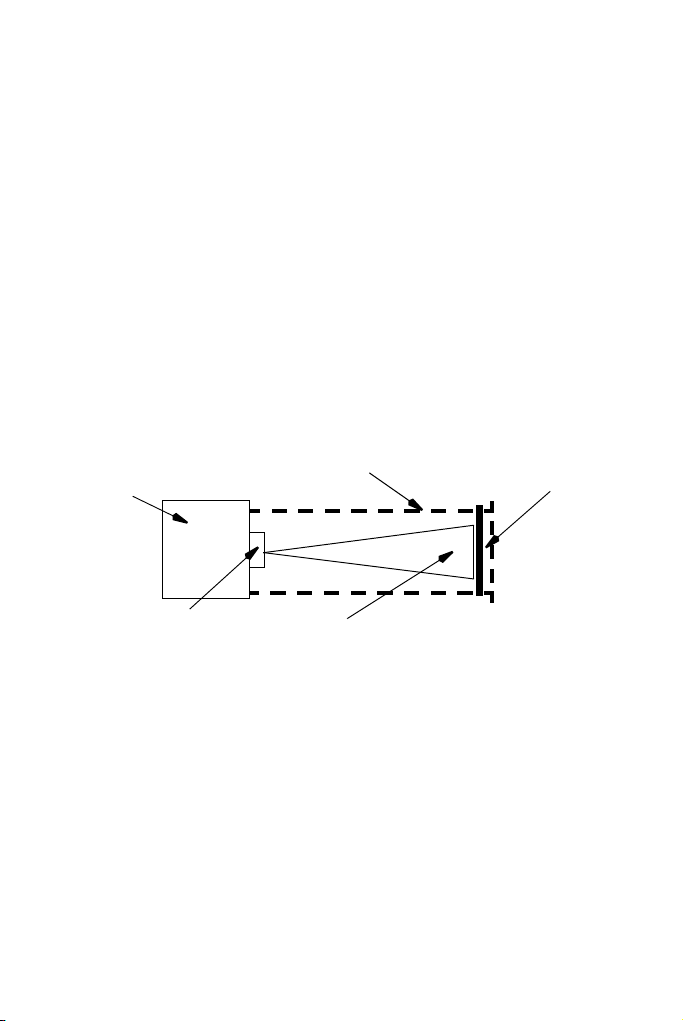
Guarding
Substrate
Laser Beam Path
Access Guard
Laser Head
Lens
The following type of guarding, using the recommended materials and
construction techniques, is required to achieve a safe installation.
WARNING: Never install a laser in such a way that the lens
points to a door or in the direction of an
operator.
When designing a housing for a fibre laser, always use overlaps where
possible to trap the laser light inside the housing, especially for mark on
the fly applications where a product inlet and outlet to the housing are
needed
Access Guards
Access guards are required to prevent direct human access to the laser
beam. In practice, this requires full guarding of the area between, and
including, the laser output lens and the area to be marked on the
substrate.
Note: Guarding is required behind the substrate to prevent access to
the laser beam when the substrate is removed, or following
accidental burn through of the substrate.
17
Page 19
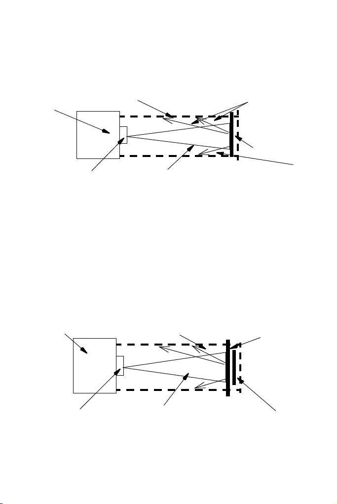
Visor Guards
Substrate
Laser Beam Path
Access/Visor Guard
Laser Head
Lens
Scattered
Radiation
Scattered
Radiation
Substrate
Laser Beam Path
Access Guard
Laser Head
Lens
Beam Stop
Visor guards are required to prevent the escape of scattered radiation.
Often the access guarding can be designed to perform this function
without the need of an extra guard.
WARNING: Visor guards have to be installed at a
minimum distance of four times the focus
distance to the laser beam.
Beam Stop Guard
A beam stop guard is required for applications where guarding material
is fitted within 100mm of the laser lens focal plane. The beam stop is to
prevent burn through of the guard should the laser be repeatedly
operated without the substrate in position. The beam stop must be
capable of absorbing the full output power of the laser for a period of
eight hours and be large enough to cover the complete laser marking
field area.
18
Page 20

Materials
All guard materials must be opaque to 1040 to 1200 nanometers
wavelength laser light produced by the fibre laser. Guards may be
metallic and non-reflecting, however if a see-through guard is required
a material opaque 1030 to 1200 nanometers wavelength laser light
must be used.
See through guards must be special laser safety windows.
Always use non-reflecting materials.
The thickness of the guard material depends on the mechanical
strength required, and the amount of ‘burn through’ anticipated. For the
purpose of adequate mechanical rigidity, a thickness of at least two
millimetres, and preferably three millimetres of steel plate is
recommended. To ensure laser safety a greater thickness of the guard
material may be required.
In a fault condition, these materials withstand the laser beam for a
limited time before the beam burns through. The laser must therefore be
monitored to avoid a risk of fire.
A ceramic or metal plate may be used as a beam stop. A greater
thickness is required to achieve the “eight hour burn through”
requirement.
Guidance regarding laser guards can be found in EN60825-Part 4.
19
Page 21

Beam Delivery Cable (Fibre)
The beam delivery cable is not Class 1 under a worst case single fault,
no cable break or fibre break detection is offered on this product. The
integrator must either include the beam delivery cable inside the Class
1 enclosure with the Pulsed Laser Aperture or undertake suitable
measures to ensure that under reasonable use, the cable is suitably
positioned to prevent it from becoming damaged or mishandled.
The beam delivery cable has not been designed for robotic
applications. The Laser must not be designed into systems where the
Beam Delivery Cable will be subject to high levels of acceleration,
torsion and twist, or combination thereof. If this is a requirement for the
integration, please contact Domino to discuss the application in more
detail.
The minimum bedding radius (r) for the fibre is 75mm.
20
Page 22

Interlock Switches
Interlock switches must be fitted to all access guards preventing access
to the laser output lens and marking area that can be opened without
the use of access tools.
Interlock switches must be wired into the laser control circuit so that the
laser beam is disabled when the guard is removed.
Emergency Off
Integrate the laser into the emergency off circuit of the machine into
which the laser is integrated. Install an emergency off push button near
the laser marking systems which turns off the laser. Connect the
emergency off push button via the interlock circuit to the controller.
Guarding Labels
Domino recommend that the following information is prominently
displayed on the guard:
WARNING: Class 1 laser product containing an embedded
class 4 laser.
Operation of the product with safety guards
removed may result in hazardous exposure to
laser radiation.
These labels are supplied with the laser system. Additional labels are
available from Domino Printing Sciences plc as part of the Guarding
Labels Kit, Part Number L007628.
21
Page 23

OPERATION
Optional
TouchPanel
Laser key switch
BCP 7
Controller
On/Off Switch
Laser Unit
(Laser Box)
Scanner Head
Laser Lens
Mains
connector
Laser Unit
(Laser Module)
Laser Fibre
Beam Delivery
F-Series laser Marking System
22
Page 24

Controls and Indicators
Key switch
On/Off Button
Indicator Lamps
The User Interface, Indicator Lamps and Software icon functions are
described in the following paragraphs:
TouchPanel and Interface
The software is operated via a PC keyboard, TouchPanel or Web
Browser. An entry is confirmed with the left mouse button if PC or Web
browser are used. The optional TouchPanel if connected, allows entry
by touching the tabs and function keys on the screen. An onboard
keyboard is included in the software.
Note: The Web Browser does not support the message editor.
Controls
ON / OFF BUTTON - Starts and stops the controller and PC unit
KEY SWITCH - Starts and stops the Laser Unit (fans and laser tube)
The key switch has three positions:
• “0” Laser off
• “1” Laser ready
• “*” Laser start.
23
Page 25

Indicator lamps
Interlock 1
Interlock 2
PC Ready
Printer Ready
Printer Busy
Power supply LED
on the rear of the
laser unit.
• Interlock 1 - Illuminates when the interlock 1 is closed.
• Interlock 2 - Illuminates when all the interlocks are closed.
• PC Ready - Illuminates when the internal PC is ready.
• Printer Ready - Illuminates when the Laser is powered up and
marking system is ready to print.
• Printer Busy- Illuminates when the Laser is marking
The activation of the laser power supply is also indicated by two red
(Power) LEDs on the front and one at the rear of the laser module.
24
Page 26

To scanner head
Power supply LED on the
front of the laser unit.
Shutter LEDs on the front of the laser unit
(only with shutter option)
Illuminates when shutter is open
Shutter LED
Power supply LED on the
front of the laser unit.
To scanner head
Laser Module without Shutter Option
Laser Module with Shutter Option
25
Page 27

Additional Indicators Laser Unit F220i
Interlock Indicator 1
Shutter Preparation / Error Indicator
Laser Indicator
Interlock Indicator 2
Shutter State / Error Indicator
Interlock Indicator 1 and 2
Lit GREEN Interlock 1 and 2 respectively
are closed.
Both interlock 1 LED and
interlock 2 LED are alternating
RED flashing
Both interlock 1 LED and
interlock 2 LED parallel RED
flashing
Both Interlock 1 LED and
interlock 2 LED are lit RED:
Within approximately 8 seconds after power up (boot phases of the
safety relay) the display of both interlock LEDs is not valid.
Wrong order was in the
interlock loops e.g. open and
close one loop only. Correct
and restart the process.
The interlock has been
opened while the shutter selftest was running.
An electrical error (cross
connection) was detected.
Debug wiring and restart the
process.
The safety relay is completely
shut down. Inspecting of its
display is suggested. Power
cycling is required.
26
Page 28

Shutter Preparation / Error Indicator
Blinking GREEN Waiting for start command.
Lit GREEN Ready.
Lit RED A shutter malfunction is
present
Blinking RED A shutter malfunction was
detected but no more present.
Blinking ORANGE A shutter malfunction was
detected - waiting for start
command.
Lit ORANGE: No shutter and shutter
controlling is equipped.
27
Page 29

Shutter State / Error Indicator
Lit YELLOW Shutter is open, caution laser
radiation is possible!
Lit RED Shutter temperature display
(after power-up only).
Lit RED (permanent) shutter feedback cross-check
failed.
Flashing RED while the
GREEN Shutter preparation
Shutter is close to over
temperature.
LED is lit or blinking
Blinking RED while GREEN
shutter preparation LED is
blinking
A shutter over temperature, or
sensor fail (<10°C) had
occurred. Therefore the laser
was switched off. Restart is
possible.
Flashing RED while GREEN
shutter preparation LED is off
A shutter temperature sensor
fail (<10°C) is present.
Therefore the laser is switched
off.
Blinking RED while GREEN
shutter preparation LED is off
A shutter over temperature is
present. Therefore the laser is
switched off.
Note: The GREEN shutter preparation LED blinking is suppressed if
one or both interlock is not closed.
28
Page 30

Laser Indicator / Error Indicator
Lit YELLOW Laser source ready for
emission.
Lit RED (error) Laser is not (correctly) started.
1x Flashing YELLOW Laser modulation (print
activity) missed.
2x Flashing YELLOW Laser modulation (print
activity) not permitted.
3x Flashing YELLOW Laser modulation (print
activity) missed AND not
permitted.
LED Test display on Power Up
After power up, the laser unit F220i will start an error test display in the
following sequence:
• Shutter state error; each sec. means 10° Celsius of scanner
temperature. This display shows that the temperature sensor of the
shutter housing is properly connected, and that the LED works.
Then, approximately 8 seconds after power up the 4 LED’s from top to
bottom:
• Extinguish for a moment
• Light up (RED) for 1 second each, top to bottom
• Extinguish for a moment
• Display status as described above
If unauthorised changes are performed, the warranty will be invalidated.
29
Page 31

Switching On and Off
WARNINGS: (1) The laser marking system must only be used
CAUTION: The lens cap must be removed before operation.
Switching On the Control Unit
Turn on the laser unit F220i first by switching the switch from position
“0” to “1”. At the control panel, release the On/Off button by turning it
clockwise. Wait until the SERVER RUNNING indicator has
illuminated.
Switching On the Laser Head
Turn the key switch from position “0” to position “1”. To start the laser
turn the key clockwise to the laser symbol and hold it for at least 1
second. The key automatically turns back to position “1”.
• The laser needs a warm-up phase of 3 seconds.
The PRINTER BUSY indicator will illuminate when the laser
hardware is switched on.
The PRINTER READY indicator illuminates. After initialising the
Dynamark 3 software and starting the lasers, the marking system is
ready.
Laser emission is also displayed by a red LED on the rear of the laser
unit.
for its intended purpose.
(2) The laser marking system may only be
operated by trained personnel.
(3) Operation is only allowed with all required
cables connected and all parts mounted. Do
not disconnect any cables during operation.
30
Page 32

Switching Off the Laser Head
• Turn the key switch from position “1” to position “0”. The laser
hardware is switched off.
Switching Off the Control Unit
• Press the On/Off button at the BCP7 controller. The computer will
immediately switch off.
• Turn off the laser unit F220i by switching the switch from position
“1” to “0”.
31
Page 33

F-Series Connectivity
X59 TouchPanel Connector
The F-Series is operated either via a remote TouchPanel or via a PC
running on Microsoft Windows 7®
QuickStep software.
To connect to one D-Series, the TouchPanel is connected to the X59
TouchPanel connector of the controller.
The TouchPanel then displays the UI relating to that printer.
One TouchPanel can control multiple F-Series in the same network if
required.
Details about the printer being controlled are displayed in the Home
screen which lists: the logged in user, the printer’s name and the printer
model. To connect to another printer in the network, follow the steps
below:
(1) Disconnect from the current printer by pressing the Lock button
and selecting Disconnect From Printer to display the printers’
list screen.
(2) Press the Lock button and select Unlock UI Settings, enter the
password (QS).
(3) Press Settings, select Broadcast (default) as the connection
method.
(4) Go back to the printers’ list screen and press Refresh to view a
list of all printers in the network.
(5) Select the required printer.
or Windows 8® with installed
32
Page 34

A list of favourite remote printers can be created, as follows:
(1) From the printer’s list screen, press the Lock button and select
Unlock UI Settings, enter the password (Domino1).
(2) Press Settings and select Favourite as the connection method.
(3) Press Add Favourite and fill in the required fields manually or get
a favourite printer from broadcast
(4) Select a printer from the Broadcast list.
(5) Press Add to Favourites.
Webserver
One may also connect to the printer’s UI via standard web browser. The
following web browsers are supported:
• Microsoft Internet Explorer from version 9.0 on
• Mozilla Firefox from version 22 on
• Google Chrome from version 27 on
• Apple Safari from version 6 on
Not the complete functionality of the UI is available when connecting to
the printers via a web browser.
Not available is:
• The Message Editor which is accessed via Home Screen > Settings
> Message Editor or via Home Screen > Messages > New Message
/ Edit Printing Message
33
Page 35

Quickstep Interface
Status Icons
Status Bar
Start/Stop Button
Lock
Main Menu
Selection
Buttons
Live Message
Preview
Zoom Toolbar
Printer Name
Home Screen
When starting the printer, the following Home screen is displayed.
34
Page 36

Status Icons: Displays current status of printer, e.g:
• Laser active
(Laser is busy - laser emission!)
• USB device connected
(USB device connected to
controller or TouchPanel)
• Dongle connected
(Pharma or Service dongle
connected)
Status Bar: Displays printer and alert status. If
more than one alert is present, the
highest priority alert is
displayed.
Start/Stop Button: • Enables marking
Note: If the laser unit is switched off,
it must be switched on before
marking can take place.
• Stops marking
• Triggers a print
• Restarts the Printer
Zoom Toolbar: Zooms in and out and to marking field
Live Message Preview: Main working area. Used for settings
and message creation.
Main Menu
Selection Buttons:
Navigate to the four main QuickStep
areas where all functions of the
operational software can be
accessed.
35
Page 37

Lock Button: • Locks the screen to prevent
accidental changes
• Login and logout
• Disconnects from printer
Printer Name: Shows the printer which is being
currently controlled
Status Bar
The status bar displays informal warning and error messages in different
colours:
• Green - the condition is normal, no action is required.
• Blue - the condition requires attention but does not prevent marking
except when the system is in standby mode.
• Yellow - the condition prevents marking, however if marking was
enabled and the reason for this fault has become obsolete it
automatically re-enables marking.
• Red - the condition prevents marking and requires immediate
correction.
Note: Click on the status bar to acknowledge errors.
36
Page 38

General Functions
Status Icons Status Bar
Start/Stop Button
Screen
Title
Tabs
Breadcrumb navigation
Scroll By
Page
Scroll By
Line
The following illustration shows the Global Print Settings screen and the
various screen areas.
Click long on a button to get a description. Click long on a button of the
Settings area to move this button to the Home screen.
Note: The breadcrumb navigation shows the current location inside
the menu structure. One can switch the user interface level by
clicking on the icons; it is also a quick way to return to the home
screen from any page.
37
Page 39

Initial Setup
The initial setup configures the overall look of the interface and also
configures basic settings and presets for printer operation.
Display Settings
Home > Settings > Regional > Language and Keyboard
Set:
• Language.
• Keyboard layout.
•IME Scheme.
• Primary currency.
Setting the Master Clock
Home > Settings > Regional > Date and Time
Set:
• System date.
• System time (24 hour clock).
• Time zone.
• Automatic Daylight Saving Time.
• Setup the Network Time Protocol.
38
Page 40

Security Management
Password protection prevents unauthorised changes to the software,
and unauthorised operation of the laser marking system.
Some functions can only be accessed from higher user levels; the
higher the user level, the more functions are available. The current user
level is displayed in the Title Bar across the top of the user interface
screen.
The functions that can be accessed for each user level are as follows:
User Level Functions Password
Logout View the main functions none
Operator Start / stop marking, select
op
message, acknowledge alerts
Supervisor Create/Edit messages; Change
sv
Marking Parameters; Access to
Editor and Save Editor
Administrator Edit most of the setup Not
published
Service Access everything Daily
changing
Extended system parameter settings can only be changed after
entering the Administrator password. This password is only known by
employees authorised by Domino.
Note: If unauthorised changes are performed, the warranty will be
invalidated.
Changing the passwords after the initial installation is recommended.
39
Page 41

Creating and Editing a Message
Tex t Barcode
(MRC)
Image Arc
Rectangle
Clone Item
Add Text
(1) Select Messages > New Message or Settings > Message Editor
to open the Message Editor.
(2) Press on the screen within a specific area of the Message Editor
where you require the item to appear. A cross hair will appear at
this location.
(3) Select the Add icon.
The Add sub-menu displays.
(4) From the sub-menu select the Text icon.
Note: Change keyboards by selecting the appropriate Alternative
Keyboard icon at the bottom of the text entry screen.
(5) Enter the required text using the keyboard and select the green
tick icon when finished.
(6) To change text, select the text item and then the Keyboard icon
on the Edit sub-menu.
(7) To change text parameters (Object Name, Position, Bold, Width
etc.), use the sub-menu (Font, Alignment) or select More…
(8) To delete an object, select the object and select the delete
icon of the Edit menu
(9) Activate the message for printing by sending it to the printer
via the File menu
40
Page 42

Add a New Barcode
To add a barcode to the message:
(1) Press on the screen within a specific area of the Message Editor
where you require the item to appear. A cross hair will appear at
this location.
(2) Select the Add Barcode icon and select the type and
specification required from the list and editable text boxes.
(3) Use the Text, Variable, Edit Variable and Properties tabs to enter
the barcode data.
(4) Select the green tick icon to insert the code into the message.
(5) Edit the barcode by highlighting the barcode within the
message and using the sub-menu or by selecting More…
(6) Activate the message for printing by sending it to the printer
via the File menu .
Add an Image
To insert an image into the message:
(1) Press on the screen within a specific area of the Message Editor
where you require the item to appear. A cross hair will appear at
this location.
(2) Select the Image icon from the Add menu.
(3) An images folder stored in the printer will open.
(4) Browse for the required image.
(5) Select the green tick icon to insert the image.
Note: Monochrome Bitmap (*.bmp), DXF (*.dxf) (up to Version 12,
information about 3-dimensional objects is discarded, fonts and
labels are not supported) and Hewlett Packard Graphics
Language HPGL (*.plt) black white graphic file formats are
supported.
Supported commands for HPGL import are: Arc Absolute, Arc
Relative, Plot Absolute, Plot Relative, Pen Up, Pen Down
(6) Select the Move icon to move the copied item to the
desired location within the message.
(7) Activate the message for printing by sending it to the printer
(8) Use the File Manager (Home > Settings > File Manager) to copy
via the File menu .
an image from a USB device to the controller.
41
Page 43

Add a New Variable
Message or system variables may be added. Message variables may
only be used in the message in which they have been created. System
variables can be used in all messages.
• Message variables are created via Home > Settings > Message
Editor >
Add > Text > Add Variable .
• System variables are created via Home > Settings > Message Editor
>
File > Add/Edit Variable > Add Variable .
Note: System variables are referenced within message via a link. Insert
a link into a message to use a global variable.
The following variables can be created and added to the message:
• Clock (message & system).
• Counter (message & system).
• Prompted Field (message only).
• Link (message only).
• Script (message only).
• Coding (message only).
• Shift Code (message only).
• Text Insert (message & system).
• Text Variable (message & system).
• Text Link (message only).
Notes: (1) System variables are empted on a power cycle.
(2) All steps below are described for local variables as they
are the same for global variables.
42
Page 44

Add a New Clock
To add a new offset clock to the message:
(1) Press on the screen within a specific area of the Message Editor
where you require the item to appear. A cross hair will appear at
this location.
(2) Select the Add icon.
(3) From the sub-menu select the Add Text icon.
(4) Select +Variable > +Create New > Clock.
(5) The scope cannot be changed - use the File menu to create a
global counter.
(6) Enter a name for the clock or use the default name and use the
drop down lists to select the format.
(7) Select the required offset parameters (Days, Months, Years and/
or Hours, Minutes, Seconds and/or Weeks) and add values
using the keyboard. Select the green tick icon when each
parameter is completed.
(8) Review the entered information and select the green tick icon if
correct or press in the required field to add or change values.
(9) Select the green tick icon to enter the offset clock into the
message.
(10) Activate the message for printing by sending it to the printer
via the File menu .
Add a New Counter
To add a new counter to the message:
(1) Press on the screen within a specific area of the Message Editor
where you require the item to appear. A cross hair will appear at
this location.
(2) Select the Add icon.
(3) From the sub-menu select the Add Text icon.
(4) Select +Variable > +Create New > Counter.
(5) The scope cannot be changed - use the File menu to create a
global counter.
(6) Enter a name for the counter and enter the Format String “N” for
numerical and “A” for alpha characters.
(7) Select a Leading Character Mode from the drop down options:
None, Blank or Custom. If a custom character is selected in the
Leading Character box, enter the character required.
43
Page 45

(8) In the Step Control box, select the option required to activate
the increment:
Print Start
User Input (Rising Edge)- specify the User Input to be used
User Input (Falling Edge)- specify the User Input to be used
(9) In the External Reset box, select None, Mark Enable,
Application Start, Message Load, User input Rising Edge, User
input Falling Edge.
(10) In the Counter Repeat box, enter the number of items to be
marked before the counter increments (default value is ‘1’).
(11) Step Size sets the increment value of the selected counter from
1 to 99999. The default value is ‘1’.
(12) Set the current value in the selected alphanumeric format of the
counter.
(13) Set the start value in the selected alphanumeric format for the
counter. If the start value is larger than the end value the
counter will count backwards.
(14) Set the end value in the selected alphanumeric format of the
counter.
(15) Edit, if required, the Alpha Field String. to be used for the alpha
designators in the counters. All alphanumeric characters are
available for use in this string. The maximum string length is 26
characters. The default string is A to Z (including all characters).
(16) Select an Ending Action: Select None, Disable, User Output or
User output and disable. Select the User Output if activated.
(17) If required, set a Batch Link to another counter when this
counter has it’s end value and select the linked counter from the
drop down list.
(18) Review the entered information and select the green tick icon if
correct or press in the required field to add or change values.
(19) Select the green tick icon to enter the counter into the message.
(20) Activate the message for printing by sending it to the printer
via the File menu .
44
Page 46

Add a New Prompted Field
Prompted text fields may be inserted into messages. The content of
these text fields is entered in QuickStep after sending the message to
the printer.The content format has to be specified when creating these
text fields in a message in the Message Editor.
To add a new prompted field to the message:
(1) Press on the screen within a specific area of the Message Editor
where you require the item to appear. A cross hair will appear at
this location.
(2) Select the Add icon.
(3) From the sub-menu select the Add Text icon.
(4) Select +Variable > +Create New > Prompted Field.
(5) Enter a name or use the default name for the prompted field
object.
(6) Set a default value in the format matching the input mask for the
prompted field.
(7) Enter a prompt which is displayed on screen when the data for
the prompted field should be entered. (After sending the
message to the printer).
(8) Select an input mask for the prompted field which specifies the
type of content for the prompted field.Possible formats:
Mask Description
0 Mandatory numeric character 0-9
9 Optional numeric character 0-9
L Mandatory alpha character A-Z or a-z
? Optional alpha character A-Z or a-z
A Mandatory alphanumeric character
0-9, A-Z or a-z
a Optional alphanumeric character
0-9, A-Z or a-z
45
Page 47

C Mandatory any character
c Optional any character
# Optional currency symbol €, $, £ or ¥
& Mandatory any character or space
(9) Review the entered information and select the green tick icon if
correct or press in the required field to add or change values.
(10) Select the green tick icon to enter the prompted field into the
message.
(11) Activate the message for printing by sending it to the printer
via the File menu .
46
Page 48

Add a New Link
To add a new link to the message:
(1) Press on the screen within a specific area of the Message Editor
where you require the item to appear. A cross hair will appear at
this location.
(2) Select the Add icon.
(3) From the sub-menu select the Add Text icon.
(4) Select +Variable > +Create New > Link.
(5) Enter a name or use the default name for the link object.
(6) Specify the source of the link, e.g. a counter or a clock or
message content element. System variables are entered into a
message via a link.
(7) Select the green tick icon to enter the offset clock into the
message. The link object will have the same content as the
source object.
(8) Activate the message for printing by sending it to the printer
via the File menu .
47
Page 49

Undo / Redo
Undo Redo
New
Message
Save
Save as
Coding
Laser
Parameters
Global
Variables
Message
Properties
Send to
Printer
Undo re redo the last editing steps in the message editor including
change of settings or parameter settings.
Note: Creating a new message clears the undo cache - no undo to the
last message is possible.
File
New Message - Creates a new message.
Save - Saves the current message in a selected message store.
Save as - Saves the current message with a given name in a selected
message store.
Coding - Selects a source for the coding variable.
Laser Parameters - Create, delete and edit laser parameter sets.
Global Variables - Create global variables.
Message Properties - Message settings overwrites system settings of
Fields, Mark on the Fly, Vector Sorting and activate usable fields. Also
enables the user to activate Optical Correction, Tube Distortion and PN
Transformation.
Send to Printer - sends the current message to the printer and
activates it for printing.
48
Page 50

Edit
Edit Text
Select
Font
Alignment
Edit Object
Properties
Delete
Object
Edit menu for a text object.
Tex t Barcode
(MRC)
Image Arc
Rectangle
Clone Item
Edit Text - Opens the keyboard to edit the text content.
Select Font - Opens the list of available fonts to select a font.
Alignment - Sets the alignment of the object.
Edit Object Properties - Allows editing the properties of the object.
Delete Object - Deletes the selected object.
Add
49
Page 51

Move
Zoom in
Zoom out
Fit height
Fit Width
Zoom 100%
Zoom to
Item
Select an object in the editor by clicking on it and move it in the desired
direction by clicking on the arrow icons.
Drag and drop can also be used.Select and hold the item within the
message and move it to the desired location.
Zoom
To view the item(s) in the Message field, or the whole Message field in
a different size, select the item(s) and then select the appropriate button
from the above toolbar:
Incrementally zoom in on the message area.
Incrementally zoom out of the message area.
Fit whole message height to area.
Fit whole message width to area.
Zoom to 100% (actual size) of Message.
Zoom selected item to fit into message area.
50
Page 52

Re-order Visual Items
Sets the order of objects to print.
Select an object of the list and use the arrows to change the order.
Item Selection List
Selects multiple or all objects of a message. Select the items of the list
to be selected. Or click on “Select all” to select all objects. Click on
“Clear Selection” to have no object selected.
Resize
Resize an object by selecting it and dragging the red mark of the object.
51
Page 53

Message Store and File Management
Selecting an Existing Message
Note: Where no message is selected for printing, no live message will
be displayed in the Home screen.
(1) Select the Messages button to open the Message Store.
(2) Select the required message from the list.
(3) Choose to Edit, Preview or Send to Print.
Note: Send to Print will revert to the Home screen. The selected
message will then be displayed.
File Manager
Home > Settings > File Manager
File Manager is a useful way of reviewing and organising stored
messages, images and scripts.
Using File Manager it is easy to edit files, create new folders and copy
content between folders.
New Store: Create a new store for messages, images and
scripts.
Note: A new message store can only be
created in the messages folder.
Edit: • Rename
•Copy
•Cut
•Delete
•Details
Paste: Used with the Copy/Cut commands to add
files into folders.
52
Page 54

MAINTENANCE
Checking Fans and Air Vents
WARNING: Before undertaking any work on the laser
marking system, unplug the mains power.
The fans are located at the sides of the control unit.
A fan defect immediately poses a danger of overheating that may result
in damage to the control unit, therefore the fans must be checked once
a month.
Control Unit
(1) Check the fans for bearing noises. If bearing noise exist, the
respective fan must be replaced.
(2) Check the fan filters of the controller (2 on the left side and 2 on
the right side) for blockages and dirt. If necessary, exchange
them. This may be easily done from the outside without opening
the controller.
Cleaning the Lens
CAUTIONS: (1) Do not use compressed air from the installation
WARNING: Ensure the mains power plug is removed
The lens must be checked monthly for dust, and if necessary be
cleaned with (absolutely clean) compressed air from a can.
For all other dirt, the lens must be cleaned with Isopropyl Alcohol and
lens paper, or cotton swabs (Q-tips), as follows:
(1) Take an unused cotton swab (cotton bud) and soak one end in
Isopropyl Alcohol.
(2) Lightly wipe with ONE PASS ONLY across the surface of the
lens.
for cleaning.
(2) Water must not be used for cleaning, as the
lenses are not water resistant.
(3) Clean carefully as there is a risk of scratch marks
on the lens which will reduce the marking quality
before cleaning the lens.
53
Page 55

Cotton Swab
Lens Assembly
(3) Inspect the cotton swab. If dirt or oil is present, repeat steps (1)
to (3).
(4) Use the dry end of the cotton swab to lightly wipe excess liquid
from the lens.
General Cleaning
WARNING: The laser marking system and the connected
installation must be switched off with the
mains supply to the laser marking system
disconnected.
The outer surfaces may be cleaned with a damp cloth and a mild
cleaning agent only. No humidity must get into the system.
54
Page 56

Service: Replacement of Components
Applications without Shutter
Maximum cycles of E-Stop Relay PNOZ S4
15 Million
(opening of guard door when laser is printing)
Maximum cycles of E-Stop Relay PNOZ S4
100 Million
(opening of guard door when laser is not
printing)
Applications with Shutter
Maximum cycles of Shutter 10 Million
55
Page 57

FAULT FINDING
System Status Messages
Status
Message
11 Encoder/Line
too fast
(overflow).
12 Encoder/Line
too slow
(underflow.)
13 List buffer
repeat count
fail.
14 Maximum print
to print
distance
exceeded.
15 Print start
signal ignored.
16 Maximum laser
on time exceed
(laser disabled
by hardware).
17 Laser warm up. A short warm up
30 Scanhead
power missing.
Cause Suggested Action
The message has
not been completed
in time.
The message has
not been completed
in time.
Internal Fault. Restart the system. Contact
The maximum
distance between
print go signals has
been exceeded and
an expected print go
was not received.
A print go has been
received too soon
after the previous.
The laser has been
firing for longer than
expected.
period is required
before use.
There is no +/-15v at
the scanhead, or no
data returning from
scanhead.
Slow down the conveyor,
reduce the mark time, or
move the text upstream on
the field.
Reduce the mark time or
move the text upstream on
the field.
Domino.
Restart the system. Contact
Domino.
Restart the system. Contact
Domino.
Restart the system. Contact
Domino.
Restart the system. Contact
Domino.
Restart the system. Contact
Domino.
56
Page 58

Status
Message
31 Scanhead
temperature
out of valid
range.
32 Scanhead
warming up please wait.
33 Control unit
over
temperature.
51 Control unit
near over
temperature.
56 Printer ready to
print.
58 No Message
loaded
549 Turn keyswitch
to enable
marking
550 System
disabled
551 Aiming turned onThe aiming beam,
Cause Suggested Action
The scanhead is
cold.
The scanhead is
cold.
The temperature in
the controller is very
cold or too hot.
The controller is
getting quite hot.
Printer will print if a
print go signal
arrives.
There is no valid
message loaded
into the controller.
The safety relay
needs to be set after
an interlock has
been opened.
The keyswitch is at
position 0.
configurable in the
global settings, is
turned on.
Restart the system. Contact
Domino.
Wait for the heaters in the
scanner motors to warm the
scanners, the printer can be
used but you may
experience very minor
position errors.
Check that the fans are
working and that the filters
are not blocked.
Check that the fans are
working and that the filters
are not blocked.
Information Only.
Load a message and send it
to printer.
Turn keyswitch to start
position, or give a remote
start input (the “Play” button
on the UI will not function).
Turn the keyswitch to
position 1.
Information Only.
57
Page 59

Status
Message
552 External
Interlocks
Open
553 External
Interlock 1
Open
554 External
Interlock 2
Open
555 Air Fault Not enough air flow
556 Vacuum Fault The DPX is not
557 Filter not ok The DPX filters are
578 System
Standby
579 Printer
enabling.
580 Inconsistent
Laser On State
Cause Suggested Action
The interlock or
interlocks are open.
The interlock switch
1 is open
The interlock switch
2 is open
to cool the laser.
running.
blocked.
The keyswitch is at
position 1 but not
yet set by turning
the keyswitch or
remote start.
The laser is
switched on but
warming up.
The laser start input
level is being
overridden by a user
interface laser on
selection or by a
fault message.
Close the guards to 'make'
the interlocks.
Close the guards to 'make'
the interlocks.
Close the guards to 'make'
the interlocks.
Check the air regulator filters
and pressure settings.
Make sure the DPX is
serviceable and running.
Change the DPX filters.
Turn the keyswitch to start
position, or give a remote
start input, or press the
“Start” button on the user
interface.
Wait for the printer to be
ready.
Restart the system. Contact
Domino.
58
Page 60

Status
Message
581 Next controller
not ready
582 Controller Idle
(Multi Head
System)
583 External
Interlock has
been opened
594 Safety Relay
Fault
Cause Suggested Action
The next controller
in a “chain” in a
Multihead
configuration is not
ready.
The system is part
of a multi head
“chain” but has
been disabled (see
install options). This
is for information
only.
One or both
interlocks was
opened but is now
closed.
There was a laser
start command
present while one or
both (CAT3/4)
interlocks where not
closed.
Restart the system. Contact
Domino.
Restart the system. Contact
Domino.
Restart the system. Contact
Domino.
Make sure the interlocks are
closed before giving the laser
start input.
Note: For all other errors or messages contact Domino.
59
Page 61

 Loading...