

Page 1

C-SERIES PRINTERS
OPERATION AND
MAINTENANCE MANUAL
MODELS
C7, C16 AND C34
Page 2
DECLARATION OF CONFORMITY
We
Domino UK Ltd, Bar Hill, Cambridge, England CB3 8TU
declare under our sole responsibility that the products,
Domino C7, C16 and C34 Printers
to which this declaration relates, are in conformity with the following standards:
BS EN 60204 - 1:1992 Safety of machinery - electrical equipment of machines
73/23/EEC : Low Voltage Directive as amended by 93/68/EEC
Council Directive 89/336/EEC EMC compatibility as amended by directive
92/31/EEC of 28th April 1992
BS EN 50082 - 1:1992 Electromagnetic Compatibility-Generic Immunity
Standard
BS EN 50081 - 1:1992 Electromagnetic Compatibility - Generic Emission
Standard
EN 55022:1987 Limits and measures of measurement of radio interference
characteristics of information technology equipment
EN 55011:1996 Conducted emissions
EN 61000 - 4 - 1:1995 Electromagnetic compatibility (EMC). Part 4. Testing
and measurement techniques
EN 61000 - 4 - 2:1995 Electromagnetic compatibility (EMC). Electrostatic
discharge immunity test
EN 61000 - 4 - 3:1996 Electromagnetic compatibility (EMC). Radiated RF
immunity.
EN 61000 - 4 - 4:1995 Electromagnetic compatibility (EMC). Electrical fast
transient burst immunity test
EN 61000 - 4 - 6:1996 Electromagnetic compatibility (EMC). Direct injection
immunity to RF signals
EN 61000 - 4 - 11:1994 Electromagnetic compatibility (EMC). Part 4. Voltage
dips, short interruptions and voltage variations immunity tests.
L. J. Mason
Technical Director
2 77091 Issue 2 November 2003
Page 3

C-SERIES PRINTERS
OPERATION AND MAINTENANCE
MANUAL
MODELS C7, C16 AND C34
This manual, Domino Part No. 77091, is for use in the maintenance of Domino
C7, C16 and C34 printers.
Users of this equipment are warned that it is essential to read, understand and act
according to the information given in Health and Safety, page 9. This part of the
manual also specifies a set of symbols which are used elsewhere in the manual to
convey special warnings or requirements. It is, therefore, essential that users are
also familiar with these symbols and act accordingly.
All rights reserved. No part of this publication may be reproduced, stored on a
retrieval system, or transmitted in any form, or by any means, electronic,
mechanical, photocopying, recording or otherwise, without the prior permission
of Domino UK Ltd.
Domino UK Ltd has a policy of continuous product improvement, the Company
therefore reserves the right to modify the specification contained in this manual
without notice.
© Domino UK Ltd 2001.
For sales, service and inks please contact:
Domino UK Ltd Domino Amjet Inc
Bar Hill 1290 Lakeside Drive
Cambridge CB3 8TU Gurnee IL.60031
England U.S.A.
Tel:+44 (0)1954 782551 Tel:(001) 847 244 2501
Fax:+44 (0)1954 782874 Fax:(001) 847 244 1421
77091 Issue 2 November 2003 3
Page 4

FCC Notice
This equipment has been tested and found to comply with the limits for a Class A
digital device, pursuant to Part 15 of the Federal Communication Commission
(FCC) Rules. These limits are designed to provide reasonable protection against
harmful interference when the equipment is operated in a commercial
environment.
This equipment generates, uses and can radiate radio frequency energy and, if not
installed and used in accordance with the instruction manual, may cause harmful
interference to radio communication. Operation of this equipment in a residential
area is likely to cause harmful interference, in which case, the user will be required
to correct the interference at his own expense.
If this equipment does cause harmful interference to radio or television reception,
which can be determined by turning the equipment off and on, the user is
encouraged to try to correct the interference by one or more of the following
measures:
• Re-orientate or relocate the receiving antenna
• Increase the separation between the equipment and receiver
• Connect the equipment into an outlet on a circuit different from that to
which the receiver is connected
• Consult the dealer or an experienced radio/TV technician for help.
Any changes or modifications not expressly approved by the manufacturer could
void the user's authority to operate the equipment.
TÜV CERTIFICATION
This product has been designed for maximum safety, and has been certified as such
by TÜV Product Services.
Modifications to this machine that are not approved by Domino, or the use of
non-Domino approved spares, will invalidate the CE mark and the TÜV
certification.
4 77091 Issue 2 November 2003
Page 5

AMENDMENT RECORD
Amendment Date
All Parts at Issue 1 October 2001
All Parts at Issue 2 November 2003
77091 Issue 2 November 2003 5
Page 6

6 77091 Issue 2 November 2003
Page 7

CONTENTS
HEALTH AND SAFETY . . . . . . . . . . . . . . . . . . . . . . . . . . . . . . . . . . . . . . . 9
Introduction . . . . . . . . . . . . . . . . . . . . . . . . . . . . . . . . . . . . . . . . . . . . . . 9
Basic Requirements . . . . . . . . . . . . . . . . . . . . . . . . . . . . . . . . . . . . . . 9
Storage . . . . . . . . . . . . . . . . . . . . . . . . . . . . . . . . . . . . . . . . . . . . . . . 10
Fire Risk . . . . . . . . . . . . . . . . . . . . . . . . . . . . . . . . . . . . . . . . . . . . . 10
Spillages and Disposal . . . . . . . . . . . . . . . . . . . . . . . . . . . . . . . . . . . . 10
SYSTEM OVERVIEW . . . . . . . . . . . . . . . . . . . . . . . . . . . . . . . . . . . . . . . 11
Introduction . . . . . . . . . . . . . . . . . . . . . . . . . . . . . . . . . . . . . . . . . . . . . 11
How it works . . . . . . . . . . . . . . . . . . . . . . . . . . . . . . . . . . . . . . . . . . . . . 12
Ink . . . . . . . . . . . . . . . . . . . . . . . . . . . . . . . . . . . . . . . . . . . . . . . . . . 20
The Base Unit . . . . . . . . . . . . . . . . . . . . . . . . . . . . . . . . . . . . . . . . . 21
One Litre Base . . . . . . . . . . . . . . . . . . . . . . . . . . . . . . . . . . . . . . 21
Three Litre Base . . . . . . . . . . . . . . . . . . . . . . . . . . . . . . . . . . . . . 25
The Print Head . . . . . . . . . . . . . . . . . . . . . . . . . . . . . . . . . . . . . . . . 27
INSTALLATION . . . . . . . . . . . . . . . . . . . . . . . . . . . . . . . . . . . . . . . . . . . . 30
Where to Site the Printer . . . . . . . . . . . . . . . . . . . . . . . . . . . . . . . . . 30
Buffer plate . . . . . . . . . . . . . . . . . . . . . . . . . . . . . . . . . . . . . . . . . . . . 32
Mounting the printer . . . . . . . . . . . . . . . . . . . . . . . . . . . . . . . . . . . . 32
Voltage Setting . . . . . . . . . . . . . . . . . . . . . . . . . . . . . . . . . . . . . . . . . 36
One Litre Base . . . . . . . . . . . . . . . . . . . . . . . . . . . . . . . . . . . . . . 37
Three Litre Base . . . . . . . . . . . . . . . . . . . . . . . . . . . . . . . . . . . . . 38
All Models . . . . . . . . . . . . . . . . . . . . . . . . . . . . . . . . . . . . . . . . . 39
Connecting an Ink Bottle . . . . . . . . . . . . . . . . . . . . . . . . . . . . . . . . . 41
Connecting the Print Head . . . . . . . . . . . . . . . . . . . . . . . . . . . . . . . . 43
Priming the System . . . . . . . . . . . . . . . . . . . . . . . . . . . . . . . . . . . . . . 44
Purging the Print Head . . . . . . . . . . . . . . . . . . . . . . . . . . . . . . . . . . . 44
Two Line LCD Models . . . . . . . . . . . . . . . . . . . . . . . . . . . . . . . . 45
Four Line LCD Models . . . . . . . . . . . . . . . . . . . . . . . . . . . . . . . . 45
All Models . . . . . . . . . . . . . . . . . . . . . . . . . . . . . . . . . . . . . . . . . 46
PROGRAMMING AND PRINTING . . . . . . . . . . . . . . . . . . . . . . . . . . . . 47
Selecting a language . . . . . . . . . . . . . . . . . . . . . . . . . . . . . . . . . . . . . 47
Password Protection . . . . . . . . . . . . . . . . . . . . . . . . . . . . . . . . . . . . . 47
Setting the Clock . . . . . . . . . . . . . . . . . . . . . . . . . . . . . . . . . . . . . . . 48
Creating a Message . . . . . . . . . . . . . . . . . . . . . . . . . . . . . . . . . . . . . . 51
Printing a Message . . . . . . . . . . . . . . . . . . . . . . . . . . . . . . . . . . . . . . 53
77091 Issue 2 November 2003 7
Page 8

CONTENTS
Adjusting the Dot Size . . . . . . . . . . . . . . . . . . . . . . . . . . . . . . . . . . . . 54
Adjusting the line print density . . . . . . . . . . . . . . . . . . . . . . . . . . . . .55
Adjusting the Speed . . . . . . . . . . . . . . . . . . . . . . . . . . . . . . . . . . . . . .56
Adjusting the delay . . . . . . . . . . . . . . . . . . . . . . . . . . . . . . . . . . . . . .59
Setting the Print Direction . . . . . . . . . . . . . . . . . . . . . . . . . . . . . . . . .61
Setting the Print Orientation . . . . . . . . . . . . . . . . . . . . . . . . . . . . . . .62
Product Count . . . . . . . . . . . . . . . . . . . . . . . . . . . . . . . . . . . . . . . . .64
Setting Up a Second Password . . . . . . . . . . . . . . . . . . . . . . . . . . . . . .65
Clearing all Messages . . . . . . . . . . . . . . . . . . . . . . . . . . . . . . . . . . . . .66
FORMATTING MESSAGES . . . . . . . . . . . . . . . . . . . . . . . . . . . . . . . . . . .67
Formatting Text . . . . . . . . . . . . . . . . . . . . . . . . . . . . . . . . . . . . . . . .67
Slashed and Non-Slashed Zeros . . . . . . . . . . . . . . . . . . . . . . . . . . . . .68
Bold . . . . . . . . . . . . . . . . . . . . . . . . . . . . . . . . . . . . . . . . . . . . . . . . .68
Text Size . . . . . . . . . . . . . . . . . . . . . . . . . . . . . . . . . . . . . . . . . . . . . .69
Standard Text Sizes . . . . . . . . . . . . . . . . . . . . . . . . . . . . . . . . . . . . . .70
Box Counting . . . . . . . . . . . . . . . . . . . . . . . . . . . . . . . . . . . . . . . . . .74
Pallet Counting . . . . . . . . . . . . . . . . . . . . . . . . . . . . . . . . . . . . . . . . .76
Setting Up Counting . . . . . . . . . . . . . . . . . . . . . . . . . . . . . . . . . .76
Printing the Count . . . . . . . . . . . . . . . . . . . . . . . . . . . . . . . . . . . .77
Printing the Date and Time . . . . . . . . . . . . . . . . . . . . . . . . . . . . . . . .78
Printing a Sell-by-Date . . . . . . . . . . . . . . . . . . . . . . . . . . . . . . . . . . .80
Start code . . . . . . . . . . . . . . . . . . . . . . . . . . . . . . . . . . . . . . . . . . 81
Incremental value . . . . . . . . . . . . . . . . . . . . . . . . . . . . . . . . . . . . .81
Date code letters . . . . . . . . . . . . . . . . . . . . . . . . . . . . . . . . . . . . .81
End code “e” . . . . . . . . . . . . . . . . . . . . . . . . . . . . . . . . . . . . . . . .81
Printing Shift Codes . . . . . . . . . . . . . . . . . . . . . . . . . . . . . . . . . . . . .82
MAINTENANCE . . . . . . . . . . . . . . . . . . . . . . . . . . . . . . . . . . . . . . . . . . .86
General . . . . . . . . . . . . . . . . . . . . . . . . . . . . . . . . . . . . . . . . . . . . . . . . .86
Routine Maintenance . . . . . . . . . . . . . . . . . . . . . . . . . . . . . . . . . . . . . . .86
Daily . . . . . . . . . . . . . . . . . . . . . . . . . . . . . . . . . . . . . . . . . . . . . . . .87
Before Long Holidays . . . . . . . . . . . . . . . . . . . . . . . . . . . . . . . . . . . .87
Six Monthly Check . . . . . . . . . . . . . . . . . . . . . . . . . . . . . . . . . . . . . .88
TROUBLESHOOTING . . . . . . . . . . . . . . . . . . . . . . . . . . . . . . . . . . . . . . .89
The Ink Line . . . . . . . . . . . . . . . . . . . . . . . . . . . . . . . . . . . . . . . . . . .89
Flushing the Jets . . . . . . . . . . . . . . . . . . . . . . . . . . . . . . . . . . . . . . . .90
Solenoid Valve Tubing Order . . . . . . . . . . . . . . . . . . . . . . . . . . . . . . .91
8 77091 Issue 2 November 2003
Page 9

HEALTH AND SAFETY
HEALTH AND SAFETY
INTRODUCTION
Domino supplies Safety Data Sheets (SDS's) giving specific safety information with
each of its ink products. There are also warnings on each container. The
following notes are for general guidance only.
Basic Requirements
When used correctly, printing inks do not cause problems. However, everybody
using them should be familiar with the appropriate safety standards and be aware of
the precautions that should be taken. The following are basic requirements.
• Proper standards of industrial practice relating to cleanliness and tidiness must
be maintained
• Inks and their containers must be stored and handled with care
• All who come into contact with inks must be properly instructed in their
use.
Directions for safe working practices vary according to the environment. The
following are broad principles so that necessary precautions may be taken.
• Contact with the mouth must be avoided. Therefore eating, drinking or
smoking, or any personal habits or actions which may transfer ink to the
mouth, must be avoided
• Contact with the eyes must be avoided. Suitable eye protection must always
be worn whenever there is any risk of splashing or misting. If ink does get
into the eyes, first aid treatment is to flood the affected eye for 15 minutes
with saline solution, (or clean water if saline solution is not available), taking
care not to allow the water to run into an unaffected eye. Medical aid must
be obtained immediately
• Most inks contain ingredients which may injure the skin. Warning of this is
given on the SDSs. Barrier creams should be used and protective clothing
worn
• Many inks contain materials which vaporise easily and can be inhaled. Good
ventilation is necessary
• Any used cleaning materials, e.g. rags, paper wipes, are a potential fire hazard.
They must be collected for safe disposal after use
• After exposure to ink, all possible traces must be washed off as soon as
possible at the nearest washing facility.
77091 Issue 2 November 2003 9
Page 10

HEALTH AND SAFETY
Storage
Store in a cool dry place, avoiding direct sunlight. Keep in the original container
and keep the container fully closed.
Fire Risk
For an electrical fire, do not use water. If water must be used, the power MUST
BE REMOVED first.
Water-based inks will not burn, although inks based on water-alcohol mixtures
may burn if there is sufficient alcohol present. Prolonged exposure of water-based
systems to high temperatures may evaporate the water to give a flammable residue.
If there is a fire, there is a likelihood that dangerous fumes will arise from printing
inks. For this reason ink must be stored where it can be reached quickly by the fire
fighting service, and where it will not spread beyond the store.
Spillages and Disposal
WARNING: Some dried inks are highly flammable. Clean up all
ink spillages immediately. Do not allow the ink to
dry or allow any build-up of dried ink spills.
Spillages must be cleaned up as soon as possible with the appropriate solvent
materials and with regard to the safety of personnel. Care must be taken to prevent
spillages or residue from cleaning up entering drains or sewage systems.
Inks and associated fluids are materials which conduct electricity. Therefore,
power to the printer must be switched off while spillages are being cleaned up.
Printing inks and associated fluids must not be treated as ordinary waste. They
must be disposed of using approved methods according to local regulations.
10 77091 Issue 2 November 2003
Page 11

SYSTEM OVERVIEW
INTRODUCTION
The Domino C-Series is a family of high quality ink jet printers enabling printing
at speeds of up to 35 metres per minute. Each C-Series unit is designed to be
compact and efficient, requiring no external connections except power.
The C-Series printers are capable of printing up to four lines of text at once
(depending on the model used), each line containing up to 40 characters. Text
heights range from 10mm to 68mm. Each line (or lines) of text printed at once is
known as a “message”. 50 separate messages can be stored in the printer’s memory.
Once input, these messages can be recalled for printing at the touch of a button
and are entirely unaffected by power loss.
Production dates, sell-by-dates, shift codes and incremental box counting can be
generated automatically. The system is quick and easy to install and operate,
requiring minimal user input and maintenance. All communication with the
printer is made using the combination membrane keypad and LCD panel on the
top of the unit.
Ink is held in a special disposable container inside the printer case. A window in
the case allows an instant check on ink level to be made.
77091 Issue 2 November 2003 11
Page 12
SYSTEM OVERVIEW
The C7, C16 and C34 printers are robust, stand-alone units manufactured from
high quality metal and will give many years of service in even the most demanding
of environments.
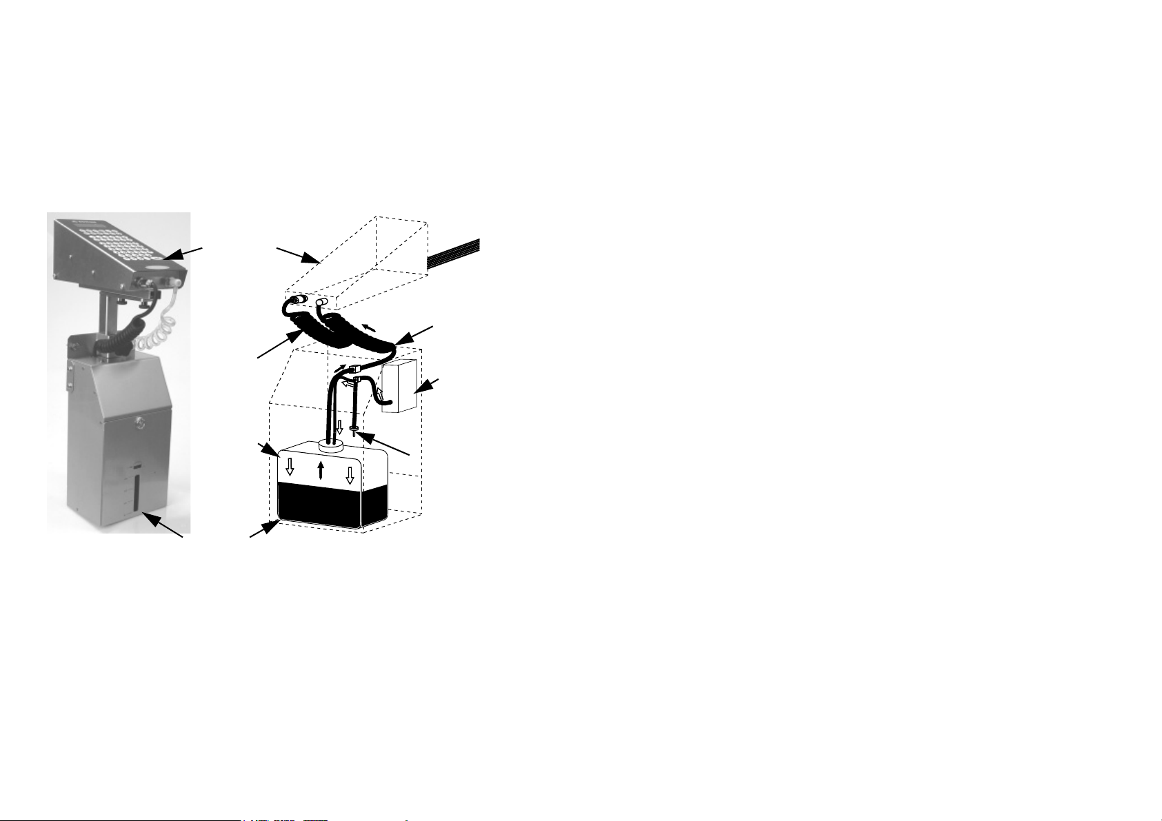
HOW IT WORKS
Each printer is manufactured in two main parts. The base unit holds the ink
storage and delivery system, power supply unit and in-built air pump.
Print Head
Print Head
Ink Supply
Print Head
Power Cable
Ink Bottle
Base Unit
Print Head and Base Unit
The print head contains the printer’s processor, memory and ink valve driver
electronics, keypad, LCD screen and photocell (or other product sensor). It also
contains all the electro-mechanical valves, tubing, filters and ink jet system
required to form a matrix of alphanumeric characters.
Air is supplied from an internal air pump mounted in the base unit, which remains
active while power is switched on. Low pressure air is fed into the sealed ink
bottle, forcing ink up into the print head. A manually operated pressure release
Air Pump
Air Pressure
Release
12 77091 Issue 2 November 2003
Page 13
SYSTEM OVERVIEW
e
valve is fitted in order to depressurise an empty ink bottle when changing to a fresh
supply.
Due to the air pump, there is a constant pressure of ink driven up the coiled
supply tube linking the base unit to the print head (a second, separate coiled tube
provides the print head with power). A quick disconnect “QD” plug at the end of
the ink supply tube is fastened into the rear of the print head.
Ink Filter
QD Ink
Connector
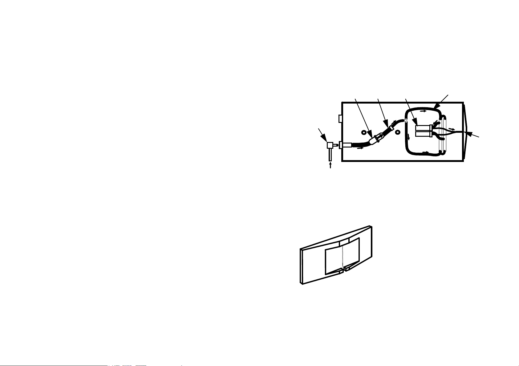
Print Head Ink Distribution
Entering the print head, the ink passes through a 25 micron ink filter which traps
any minute particles suspended in it, then an ink reducer. Finally it is distributed
to all the inlets in the solenoid valve array. The diagram above shows the ink path
in a typical print head. For clarity, only two of the valves are shown. The number
of valves and layout of the ink distribution assembly depends on the model used.
Printer Nozzle Plate
Valv esReducer
On activation, each solenoid valve allows a
measured amount of ink (still under air pump
pressure) to move forward into the outlet tube
linking the valve with the nozzle plate. The
nozzle plate consists of a series of openings
arranged vertically. The ink is ejected from
these openings in droplets, driven a few
millimetres onto the surface of whatever is to be
printed. Each time the valve is activated more
ink is released into the relevant outlet tube,
forcing another droplet of ink out of the nozzle
plate.
Ink Distribution
Assembly
Nozzl
Plate
77091 Issue 2 November 2003 13
Page 14
SYSTEM OVERVIEW
The vertical component of text is produced
by the vertical arrangement of openings in
the nozzle plate. Since the printer is fixed in
position, the horizontal component of text is
produced by the movement of product on the
conveyor. It is similar to the action of a
typewriter; the place at which printing takes
place is fixed, and the carriage moves (to the
left) correctly positioning the paper for each
character. In the case of the C-Series
printers, it is not each character which needs
to be positioned but each vertical row of dots.
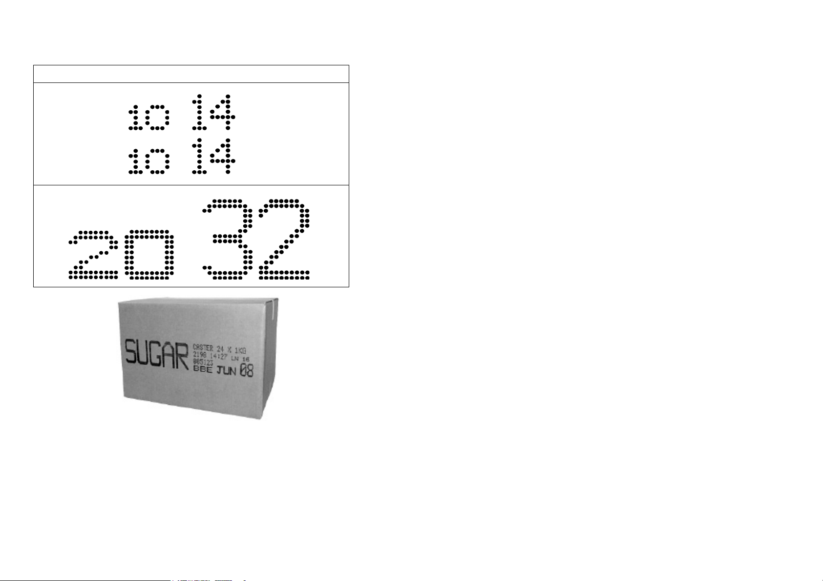
C-Series printers produce text in several
available matrices, depending on the text size
chosen and the capabilities of the model used. These matrices can range from 5 x
5 (five dots high and five dots wide) to 34 x 24.
Printing single and
two line text
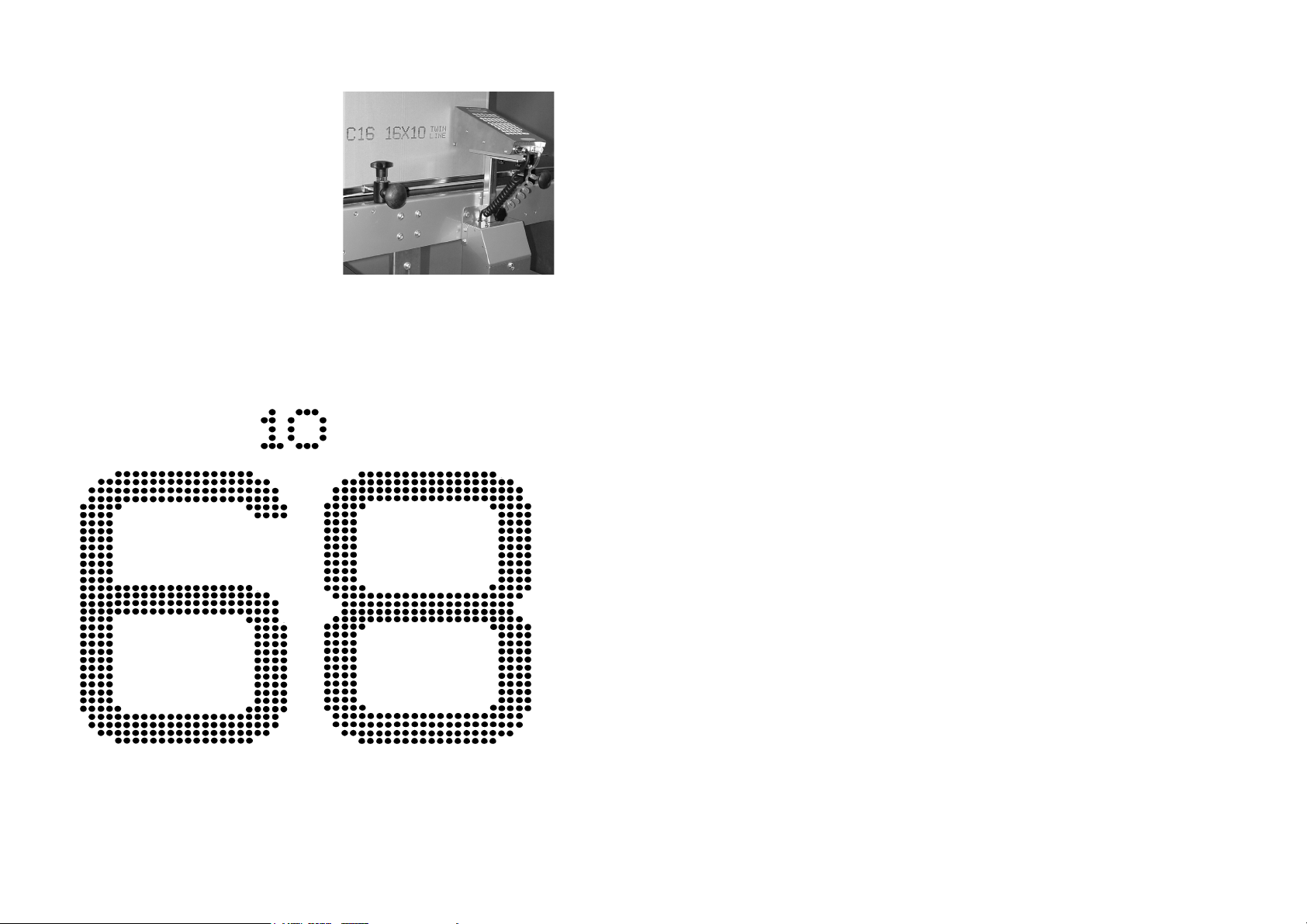
The previous diagram shows the smallest and largest matrices available in the C7,
C16 and C34 printer range. The text is to scale but not full size; the numbers give
14 77091 Issue 2 November 2003
Page 15
the actual height of the text in millimetres. Each character in the top row is
formed using a 5 x 5 matrix; each character in the bottom row is formed using a
34 x 24 matrix.
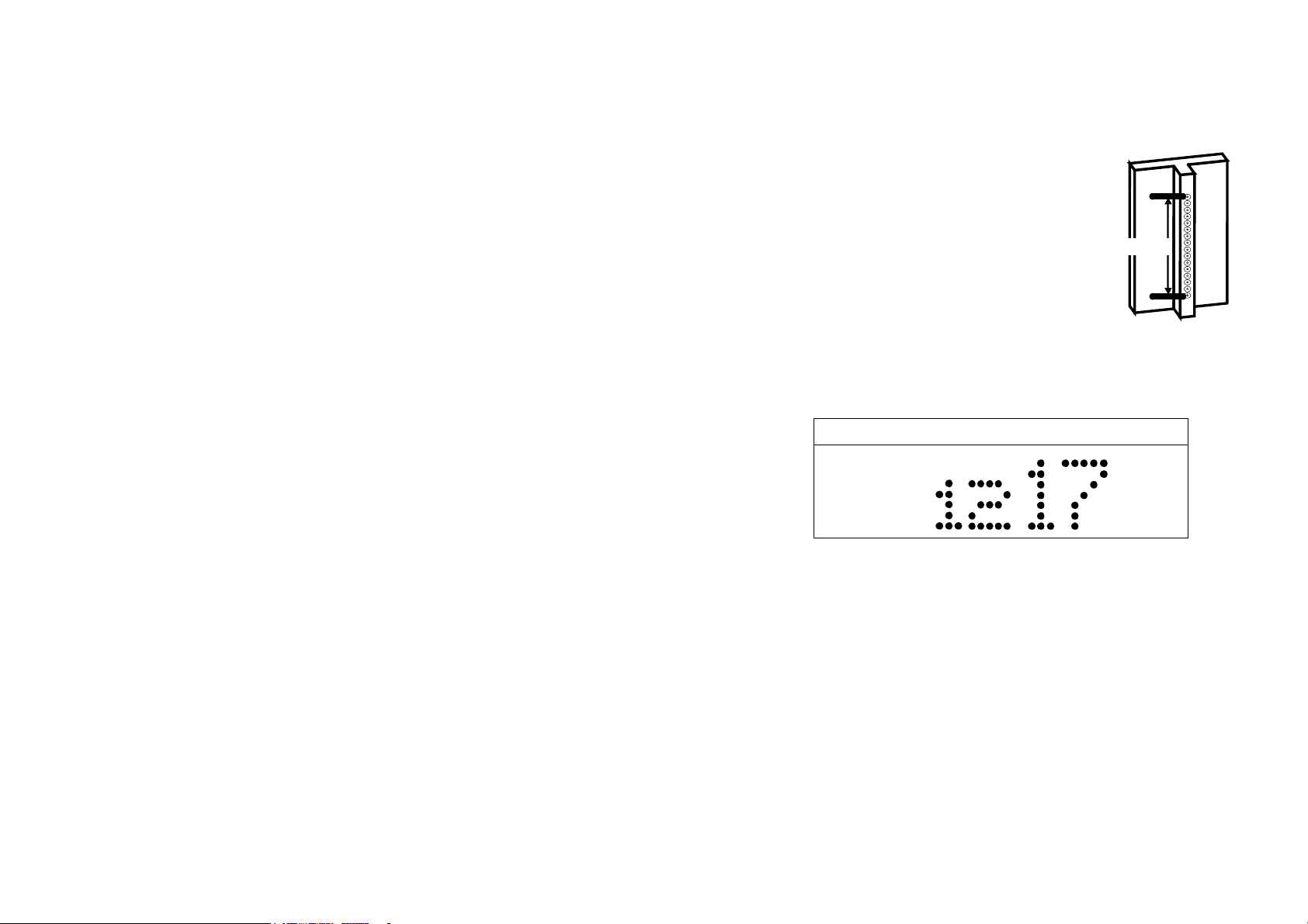
The number of jets per nozzle plate, and hence the
largest matrix available, is fixed for each model. Thus,
a C14 has 14 jets arranged in two blocks of seven.
This allows two lines of 7 x 5 matrix text to be
produced. (Note: it cannot produce one line of text
14 jets high - multi-line text requires a C14.)
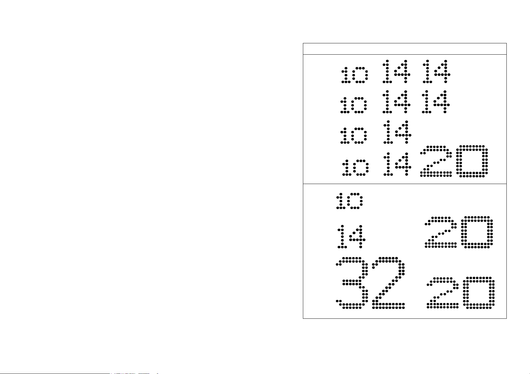
Heigh
The diagrams below show proportionally the print
capabilities of each of the printers. In each case, the
number is the height of the relevant text in
millimetres.
Nozzle Plate Height
Note: The sizes given are representative only. When
dealing with nozzle plates, the “height” is assumed
to be the measurement between the middle of the top jet and the middle of the
bottom plate in the array.
C7
The print capabilities differ widely between models. The larger model number
printers are capable of a bigger range of text sizes. The models also differ in the
size of LCD screen. Functions and features detailed in this manual are relevant to
all models in the range except where indicated.
77091 Issue 2 November 2003 15
Page 16
SYSTEM OVERVIEW
C14
An Example of a Printed Message
16 77091 Issue 2 November 2003
Page 17
SYSTEM OVERVIEW
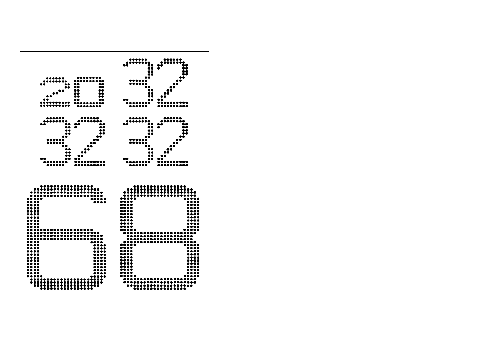
C34
77091 Issue 2 November 2003 17
Page 18
SYSTEM OVERVIEW
C34 (continued)
18 77091 Issue 2 November 2003
Page 19
SYSTEM OVERVIEW
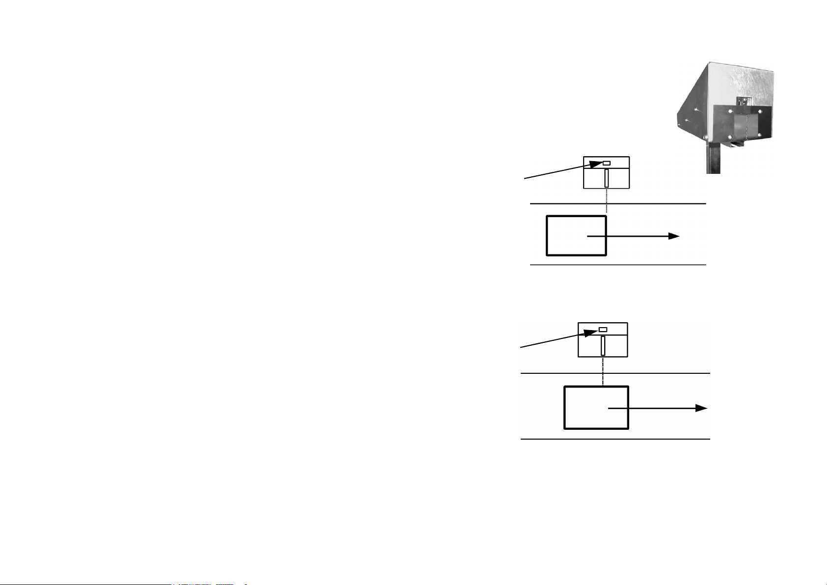
The printer is fixed to the side of a conveyor
along which move the items to be printed.
As an item reaches the print head it is
detected by a built-in photocell mounted just
above the nozzle plate. (The diagram left
shows a C16 print head. The arrangement is
slightly different for some printers, but the
principle remains the same.)
Photocell
Direction of Travel
The system then allows a short time delay to enable the item to be carried on past
the print head. This delay depends on the speed of the conveyor and the length
and position of the message and is set by the operator for each message.
Photocell
Direction of Travel
When the item is at the correct position in respect to the print head, the desired
text is printed by repeated triggering of the solenoid valves.
Meanwhile a second item may be approaching the print head. Items do not need
to be equally spaced along the conveyor since the printer senses each one
individually as it reaches the photocell.
77091 Issue 2 November 2003 19
Page 20

SYSTEM OVERVIEW
As mentioned earlier, it is the steady horizontal motion of the item along the
conveyor which produces the text. On a stationary item only a single vertical band
of ink would be produced.
The printer is capable of high volume printing (at a maximum line speed of 35
metres per minute) dependent on the speed of the conveyor. Software controls
regulate the speed at which the vertical lines of dots are produced in order to
match the speed at which the items pass by the nozzle plate.
It is important that the conveyor runs at a steady, uniform speed. Conveyors
which judder or run at variable speed will produce uneven print. On a suitable
conveyor the ink jet system is capable of good quality text due to its extremely
accurate timing and control of ink drop release.
Ink
CAUTION: Do not use ink or cleaner not supplied by Domino. The use of any
other ink or cleaner can cause serious damage to the printer. Contact
your nearest distributor or Domino Service for advice on ink and
printing applications.
Printer ink comes in a choice of colours and is specially formulated to maintain the
long life of the printer and to provide the optimum performance in a wide variety
of applications. There is no messy mixing or topping up of ink as this is supplied
in easily-changed disposable containers.
Domino’s water-based inks are best suited to porous surfaces such as cardboard,
paper and fibres. The main advantage of using water-based ink is that the ink is
less prone to drying while in the tube and on the jet openings which are exposed
to the atmosphere. Spirit-based inks tend to dry in and on the jets, creating a need
for more maintenance. Domino only use water-based ink in the C7, C16 and
C34 printers.
20 77091 Issue 2 November 2003
Page 21
SYSTEM OVERVIEW
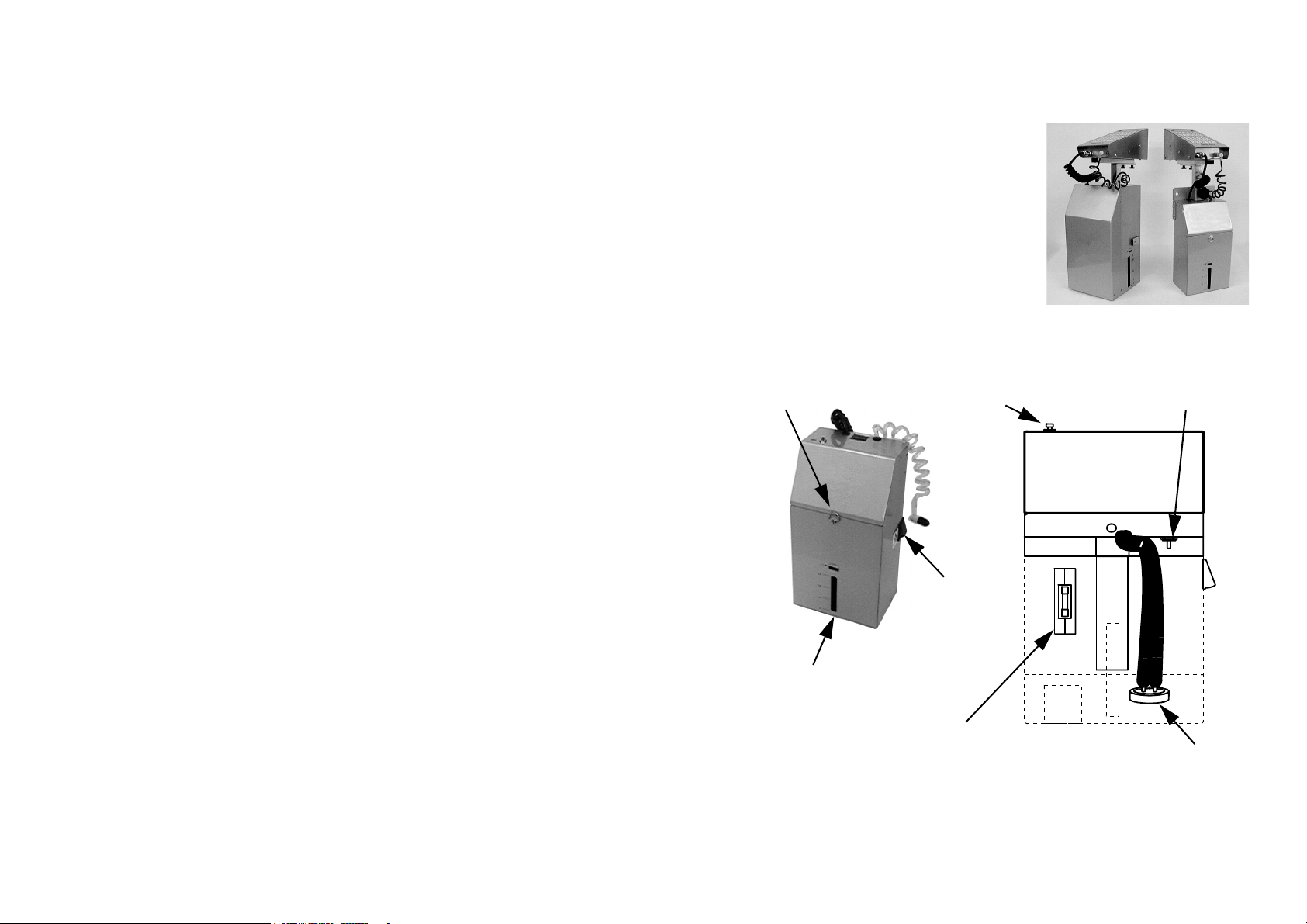
The Base Unit
Two different sizes of base unit have ink
containers of different capacities.. The C7
and C16 printers are supplied with a one litre
base as standard. The C34 is supplied with a
three litre base as standard. The larger base
with its larger capacity ink container, allows
extended operation between ink changes.
One Litre Base
In the one litre base the ink bottle is located
inside the base unit, accessed by rotating the
door catch ring on the front of the unit 90°,
allowing the door to swing down. The diagram below shows the layout of the ink
bottle compartment behind the door.
Door
Catch
Ink Level Indicator
Switch
Pressure Release
Valv e
Power
Switch
Ink Level
Window
Ink Level
Indicator Lamp
77091 Issue 2 November 2003 21
Ink Cap
Page 22
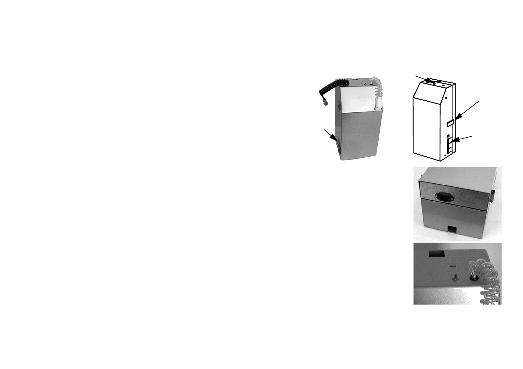
SYSTEM OVERVIEW
To check the level of ink in the bottle, press
the red push-button on the top of the base
unit. This switches on the ink level indicator
lamp inside the unit. The light from the
lamp shines through the ink bottle. The
remaining ink can be seen through the ink
level window at the front of the base unit. (If
the unit has been moved, allow the ink to
settle before checking the ink level.) It can
then be seen when the ink bottle should be
replaced.
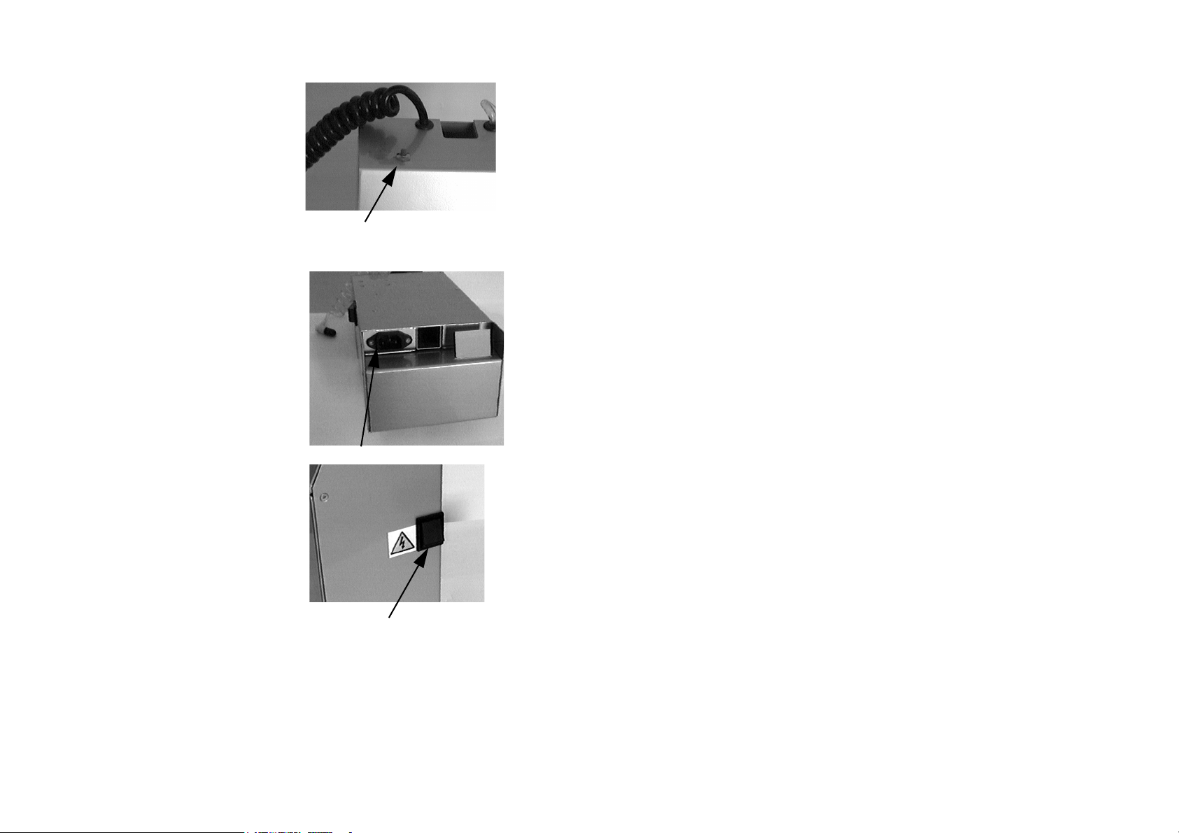
Power is supplied to the printer by the mains
input plug located on the bottom face of the
base unit, just behind the hinged door. This
is the only input that is required for
operation of the printer.
Ink Level Indicator
Switch
Power Input
The power switch is located on the right side
face of the base unit. When power is turned
on, this switch will illuminate. A serial
number label near the switch will indicate
the supply voltage to which the printer unit
is set. Before switching on the printer,
ensure that the supply matches the voltage
stated on this label. If the unit is set to the
wrong voltage, before switching on the
printer, change the voltage settings inside
the base unit as given in the
INSTALLATION chapter of this manual.
22 77091 Issue 2 November 2003
Power Switch
Page 23

SYSTEM OVERVIEW
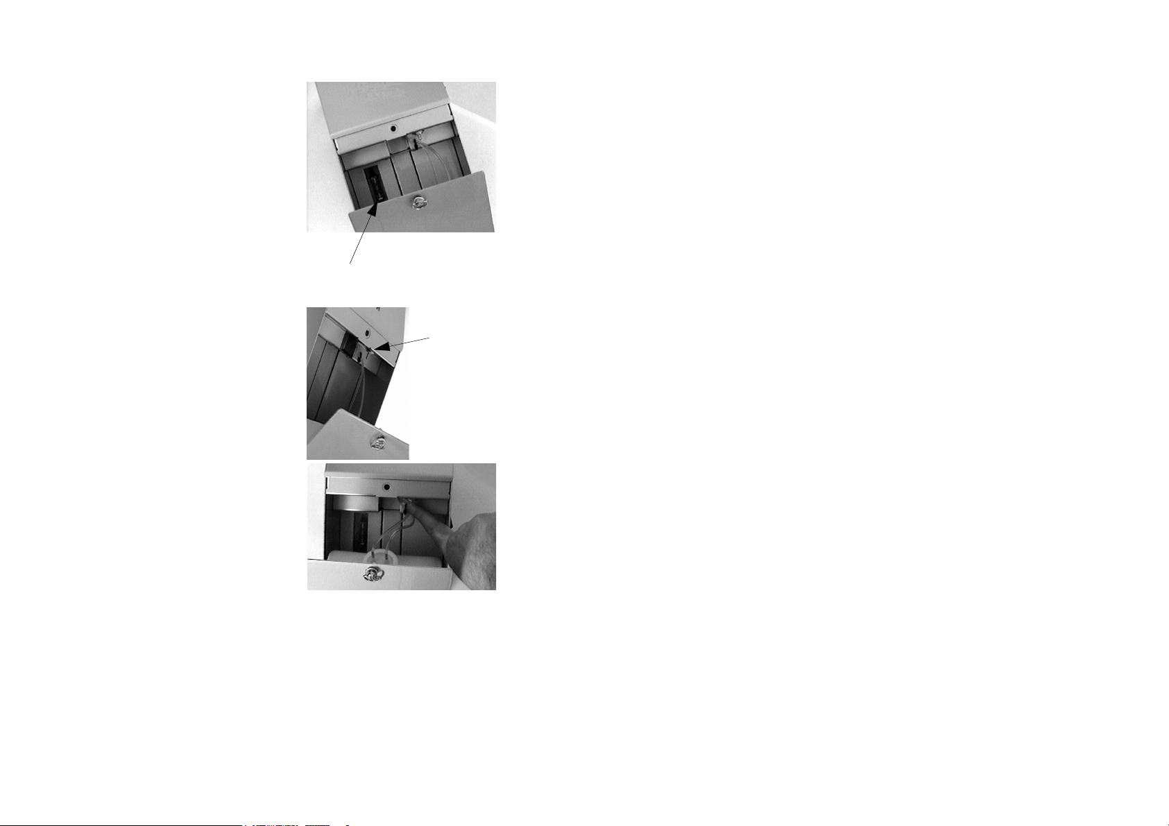
To open the ink compartment door, grasp
the door catch ring and rotate it 90° anticlockwise to disengage the catch. The door
will then fall forward on its hinge allowing
access to the interior. A stopper beneath the
door ensures that it will not trap the mains
cable.
To close the ink compartment door, reverse
this procedure. Push the catch in while
rotating it 90° clockwise until it holds firm.
Take care not to trap the ink and air lines
when closing the door.
77091 Issue 2 November 2003 23
Page 24
SYSTEM OVERVIEW
In this photo the ink level indicator lamp
(which looks like a fuse) is visible on the left
hand side of the back wall.
A pressure release valve is located just inside
the door. This valve safely depressurises the
ink bottle when it is exhausted. Since the
internal air pump keeps the ink bottle
pressurised in order to force ink up into the
print head, it is not advisable to attempt to
remove an exhausted bottle without first
depressurising it.
Ink level
indicator
Pressure
release
valve
Switch the power off (stopping the air pump)
then press the valve stem upwards to release
the pressure from the bottle. The bottle can
then be removed and discarded.
Full instructions on connecting up a new ink
bottle are given in the INSTALLATION
chapter of this manual.
24 77091 Issue 2 November 2003
Page 25
SYSTEM OVERVIEW
Three Litre Base
The three litre base is identical in operation to the one litre base; the differences are
in the location of the various components and, of course, in the size of ink bottle it
uses.
Ink level indicator
switch
Door
catch
Power
switch
The mains input plug is again located on the
bottom of the base unit, this time on the
door itself. The power switch is located on
the left side face of the base unit door and
will illuminate when power is turned on.
Ink level
window
Like the one litre base, an ink level indicator
switch is located on the top of the base unit
in the form of a red push-button. When it is
pressed down the ink level indicator lamp
will illuminate and the level of ink in the
bottle can be seen through the window on
the right side face of the base unit door.
77091 Issue 2 November 2003 25
Page 26
SYSTEM OVERVIEW
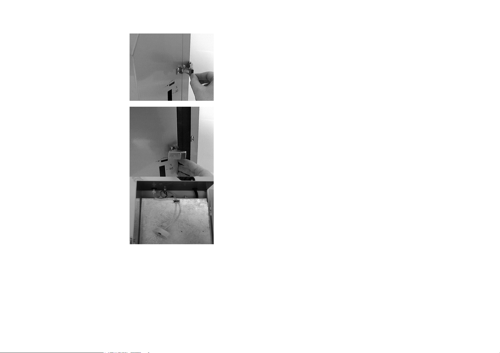
To open the ink compartment door, pull
open the door catch so that it disengages
with the rear of the base unit (as shown
right). The door can then be swung open
on its hinge allowing access to the interior.
To close the ink compartment door, reverse
this procedure. Hook the catch around the
fastening on the rear of the base unit and
press it in place. Take care not to trap the ink
and air lines when closing the door.
This photo shows the interior of the three
litre base’s door. The captive ink bottle cap
can be clearly seen hanging from its
connecting air and ink tubes. All the base
unit’s electronics are located behind the panel
in the door.
26 77091 Issue 2 November 2003
Page 27

SYSTEM OVERVIEW
The pressure release valve is located at the
top of the base unit’s door. This valve safely
depressurises the ink bottle when it is
exhausted, enabling the supply to be
renewed.
Full instructions on connecting up a new ink
bottle are given in the INSTALLATION
chapter of this manual.
Pressure Release
Valve
The Print Head
Communication with the printer is achieved
by using the built-in membrane keypad and
LCD display on the top of the print head.
The C34 incorporates a four-line LCD
display. The other models use a two-line
LCD display. This reflects the larger models’
increased print capabilities - all other
functions are exactly the same.
All printers use the same keypad layout and
communicate with the operator in the same
way, with the same keys accessing the same
options and the same prompts requesting the
same information.
Notes: (1) The keys are activated by pressure-
sensitive pads just beneath the
printed surface of the keypad. Press
once firmly in the centre of the
selected key to activate it.
(2) Do not use pens or other sharp
objects to activate the keys as serious
damage could result. The keypad
was designed for fingertip use only.
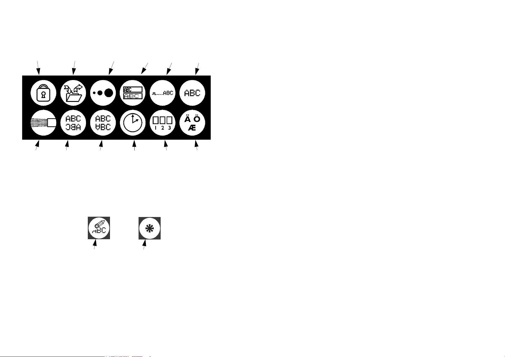
The keypad is in three sections. Pressing any of the special icon keys at the top
accesses the appropriate function as detailed in the Programming and Printing
Keypad
LCD Display
77091 Issue 2 November 2003 27
Page 28
SYSTEM OVERVIEW
section of this manual. When pressed in combination with the SHIFT key (see the
following page) some of these keys access additional functions.
Password
Create and Edit
Messages
Dot Size
Speed
Delay Print
Purge Direction Orientation Set the
Clock
The central section of the keypad contains the number keys and the BACKSPACE
and ALL keys. The BACKSPACE key is used when editing messages to delete the
character to the left of the currently high-lighted character. When pressed in
combination with the SHIFT key (see below), the BACKSPACE key clears the
entire message line while editing messages; when not editing messages this key
combination erases all the messages in the printer's memory.
Backspace key All key
The ALL key is used in many functions to select all the messages in the printer’s
memory.
The bottom section of the keypad contains the letter keys and SPACEBAR. To
the right of the letter keys, the arrow keys (in blue) are used for navigating through
messages and other entered data.
Product
Count
Set the
Language
28 77091 Issue 2 November 2003
Page 29

SYSTEM OVERVIEW
In the bottom left hand corner there are the SHIFT and DOWN SHIFT keys (in
red). The SHIFT key is used in combination with the icon keys to access
additional printer functions. It is also used in combination with the letter and
number keys to enter the special characters and punctuation marks displayed in red
in the top right hand corner of the key.
To access these
characters, use
the downshift
Shift Key
The DOWN SHIFT key is used in combination with the number keys 1 to 6 to
enter the lower case characters displayed in red in the bottom left hand corner of
the key.
The key in the bottom right hand corner of the keypad is the ENTER key. This
key is used to execute a function once data has been entered. Unlike the other
keys, the ENTER key consists of multiple pressure-sensitive pads. Ensure this key
is pressed in the correct place to activate it.
Downshift Key
To access these
characters, use
the shift key
77091 Issue 2 November 2003 29
Page 30

INSTALLATION
INSTALLATION
Where to Site the Printer
WARNINGS: (1)The printer must not be sited where there is a
risk of water splashing onto the machine. The
printer is not water-resistant.
(2)The printer must not be sited near a source of
static or electromagnetic radiation, such as
metal detectors or high current sealing
machines.
(3)The electricity supply to the printer must be of
constant voltage and current and must be free
from transient spikes and interference. Check
the voltage setting before switching on the
machine.
Before installing the system, check the shipment carefully, removing all packaging,
to ensure that all the ordered components have arrived and that there is no obvious
mechanical damage from shipping. Installation is not complicated, and should take
less than half an hour.
The printer is capable of exceptional print quality at high speed. The performance
of the system depends greatly on its proper installation. Contact your local
distributor or service technician for advice on installing the printer.
It is important to prepare the site carefully. Choose a suitable place for the printer
to be mounted to the conveyor frame. A level, straight sextion of conveyor is
required. If printing on both sides of the items, using more than one printer, both
sides of the printer must be easily accessibe for programming and maintenance.
30 77091 Issue 2 November 2003
Page 31

INSTALLATION
Beware of trailing cables. For example, the printer requires a power cable.
Therefore, ducting or some other form of cable management may be required.
The printer is equally suited to right-to-left or left-to-right conveyor travel legibility in the latter case achieved simply by reversing the direction of print using
the operating software. Reversed printing also means that it is possible to print
simultaneously on both sides of items using more than one printer.
Right to Left Conveyor Travel
Normal Printing
Each printer will need individual servicing, for example when replacing ink
bottles. A printer should not be placed in a location where it may be knocked or
jolted. The printer is also sensitive to vibration which may adversely affect print
quality.
For the best quality of print, select a power-driven section of conveyor for
mounting. Guide bars are essential to align the product to pass the print head only
just touching the front face.
Though items do not need to be equally spaced on the conveyor, there must be an
adequate gap - of at least 100mm - between them for the photocell to register the
arrival of each one. Items must not jam up on the conveyor; the photocell will not
recognise multiple products in a jam. This will result in missed products and
incorrect box counting.
Left to Right Conveyor Travel
Reversed Printing
77091 Issue 2 November 2003 31
Page 32

INSTALLATION
Avoid locations where operators or machinery moving close to the printer are
likely to trigger the photocell. Do not place the printer opposite a large reflective
area as this may also trigger the photocell. When printing on both sides of
product, never place the two printers exactly opposite - the photocells will trigger
each other.
Buffer plate
Each printer incorporates a buffer plate to
afford some protection to the nozzle plate, to
provide a degree of print-head-to-product
spacing for correct character generation and
to help prevent smearing before the ink
dries. In the C16, this is built into the nozzle
plate itself.
In all other models, the buffer plate is
separate to the nozzle plate and is bolted in
place. The position of the buffer plate may
need to be changed to correspond with the
direction of product movement on the
conveyor - make sure that the product
reaches the buffer plate before it reaches the
nozzle plate. This involves removing the
print head cover, which is explained in the
MAINTENANCE chapter of this manual.
Combined Buffer and
Nozzle Plate
Separate Buffer Plate
- Position as Required
Mounting the printer
The exploded diagram (below) shows the arrangement of components used in the
mounting of a printer with a one litre base. Items A and B are not required when
installing a three litre base as they are built into the base unit.
32 77091 Issue 2 November 2003
Page 33

INSTALLATION
H
G
F
C
I
C
A
B
B
E
A Mounting Bracket MJ/605
B Base Mounting Bolts M5x10
D
C Mounting Bolts M8x20
Mounting Washers M8
Mounting Nuts M8
D Vertical Mounting
MF006
Bracket
E Height Adjustment
M8x15
Knob
F Slide Bar MF/
005M
G Print Head Fixing
M5x6
Screws
H Clamping Plate MF/008
I Overhang Adjustment
M5x10
Screws
77091 Issue 2 November 2003 33
Page 34

INSTALLATION
(1) (One litre base only.) Using the
mounting bracket (A) as a template,
drill two holes at an appropriate place
on the conveyor.
(2) (One litre base only.) Fix the
mounting bracket to the base unit
using the M5 mounting bolts (B)
provided. These bolts thread into the
holes at the top of the longest edge of
each side of the base unit.
(3) (One litre base only.) Fix the
mounting bracket/base unit assembly
to the conveyor using the two sets of M8 mounting bolts, washers and nuts
provided (C).
(4) (Three litre base only.) Open the base
unit door and locate the fixing holes
at the rear of the cabinet. Use these
as a template to drill into the
conveyor at the appropriate place.
Fix the base unit to the conveyor
using the M8 mounting bolts,
washers and nuts provided (C).
Mounting Bolts
Vertical Mounting Bracket
Fixing Holes
34 77091 Issue 2 November 2003
Page 35

(5) Slot the vertical mounting bracket
(D) into the square section of the
mounting bracket/base unit and
tighten the height adjustment knob
(E). The horizontal arm may point
towards or away from the conveyor
depending on the application.
(6) Turn the print head upside down.
On its base are three slide bar
mounting holes. Two of the holes
(not all three) will be used to fix the
print head to the slide bar (F). Screw
the two print head fixing screws (G)
into two adjacent holes. Which two
are depends on the application - in
other words, how far from the edge of
the conveyor the product will be
moving. Do not tighten these screws
yet.
(7) Slot the slide bar (F) onto the print
head by passing the two fixing screws
through two of the “keyhole” cutouts
in the slide bar. Make sure the slide
bar does not extend beyond the
nozzle plate. Tighten the screws.
Slide Bar
Mounting Holes
77091 Issue 2 November 2003 35
Page 36

INSTALLATION
(8) Thread the slide bar onto the
horizontal arm of the vertical
mounting bracket so that the upper of
the two clamping plates (H) is inside
the slide bar. Use the two overhang
adjustment screws (I) to hold the
print head securely in position.
Print head overhang can be adjusted by
sliding the slide bar in and out, or by moving
the fixing screws to different holes in the
print head or slide bar. The vertical
mounting bracket can also be rotated 180° to
extend or shorten the overhang. The vertical
position of the print head can be adjusted
using the height adjustment knob.
Overhang
Adjustment
Screws
Height
Adjustment
Knob
Voltage Setting
WARNING: DANGER OF ELECTRIC SHOCK. Disconnect the
printer completely from the mains supply before
attempting any internal access or making any
adjustments to the PSU.
Before switching the printer on, ensure that the internal power setting is set to
match the local electricity supply - either 240v, 220v or 110v AC. The printer
will operate at either 50Hz or 60Hz.
36 77091 Issue 2 November 2003
Page 37

INSTALLATION
Normally the printer is correctly set during manufacture to match the supply
voltage in the country of destination. This is marked on the Serial Number label
next to the power switch on the side of the base unit. However, should it become
necessary to change the voltage settings, follow this procedure.
CAUTION: This procedure involves unscrewing the base unit case to expose the
circuitry inside. Do not attempt to remove the base unit case unless
qualified to do so. If unsure about mounting or connecting the
printer, call Domino Service or your local distributor for assistance.
One Litre Base
(1) Disconnect the printer from the power supply.
(2) Remove the two screws indicated below from both sides of the base unit.
(3) Swing the angled top plate of the base
unit up and backwards, taking great
care not to stress any of the cables or
pipes.
77091 Issue 2 November 2003 37
Page 38

INSTALLATION
(4) The printer power supply (PSU) is located in the top left hand corner of
the exposed circuitry. Changing the voltage setting requires moving the
jumper pins on this board. It may also require changing the fuse located
nearby. (Jump to the section “ALL MODELS” to continue.)
Three Litre Base
(1) Disconnect the printer from the power supply.
Base Unit
Screws
(2) Remove all of the visible screws from both sides of the base unit door.
There will be six in total.
(3) Open the base unit door carefully,
and rotate the plate containing the
electronics. Take great care not to
stress any of the cables or pipes.
(4) The printer power supply (PSU) is
located in the middle of the exposed
circuitry. Changing the voltage
setting requires moving the jumper
pins on this board. It may also require
changing the fuse located nearby.
Power
Supply
Unit
(PSU)
38 77091 Issue 2 November 2003
Page 39

INSTALLATION
All Models
(5) Set the jumpers and fuse to match the input voltage as shown below (1L
base) and over the page (3L base)
.
One Litre Base Link Settings and Fuse Ratings
240V
220V
110V
0.25A
0.25A
0.5A
Jumpers
Fuse
Location of Jumpers and Fuse in
One Litre Base
77091 Issue 2 November 2003 39
Page 40

INSTALLATION
Three Litre Base Link Settings and Fuse Ratings
240V
220V
110V
0.25A
0.25A
0.5A
Fuse
Jumpers
Location of Jumpers and Fuse in
Three Litre Base
(6) Carefully reassemble the base unit and tighten all the screws. Complete the
installation process before switching on the machine.
Note: The voltage setting on the serial number label must be changed to correspond to the
PSU setting.
40 77091 Issue 2 November 2003
Page 41

INSTALLATION
Connecting an Ink Bottle
In the photos on this page a one litre base is shown; follow exactly the same
procedure for the three litre base.
The ink cap is attached to the inside of the base unit by its two feed pipes (air in
and ink out). The two metal probes pierce the seal into the ink bottle allowing an
air-tight, ink-tight seal to be formed.
(1) If installing the printer for the first
time, there may be a piece of
protective tubing placed over the ends
of the probes. Pull off this piece of
tubing carefully - the probes are very
sharp. Check that both “O” ring
seals are present around the supply
stems, otherwise air and ink leaks may
occur.
WARNING: If replacing an empty ink bottle, remember to switch
the power off and press the pressure release valve
before unscrewing the old bottle.
(2) Discard the transit cap from the new
ink bottle and push the bottle into
place. In the one litre base it slots
down into the door of the unit. In
the three litre base it sits on the ledge
at the bottom of the unit.
77091 Issue 2 November 2003 41
Page 42

INSTALLATION
(3) Push the air and ink probes into the correct holes in the ink bottle,
puncturing the seals. Notice that the probes have different diameters which
must be aligned correctly with the holes in the bottle, otherwise damage
will result if the cap is forced on.
Note: Ensure that the
large and small
probes go into the
correct holes.
(4) Press the centre of the probe assembly
firmly with the thumbs to make sure
that both probes have pierced the
seals. Then screw the bottle cap in
place.
(5) Tighten the bottle cap firm (hand
tight only). Arrange the air and ink
tubes so that when the door is shut
they cannot be trapped in the door
mechanism. Switch the printer on
(activating the air pump) before
closing the door and check the cap
thoroughly for leaks.
42 77091 Issue 2 November 2003
Page 43

INSTALLATION
Ensure the ink level is checked regularly (by pressing the ink level indicator switch
and looking through the window on the base unit door) since an exhausted ink
bottle will draw large quantities of air into the system. The process of changing
the ink supply will always cause some air bubbles to become lodged in the ink feed
tubes - these must be removed by priming the system.
Note: If the printer is not going to be used for periods of longer than three weeks, it is
recommended that to replace all the ink in the system with Domino flushing fluid for
the idle period.
Connecting the Print Head
There are two connections to the print head:
a black coiled power cable and a translucent
coiled ink supply tube fitted with a quick
disconnect (“QD”) plug.
Connect the power cable to the socket on
the left hand side of the print head (under
the ledge). The pins are arranged to prevent
incorrect insertion. Screw the cable firmly
in place.
Remove the shipping caps from the end of
the ink supply tube and the QD socket on
the right hand side of the print head.
Connect the QD plug by simply lining it up
with the socket and pressing it in place. A
“click” will be heard as the locking plate
secures the plug.
77091 Issue 2 November 2003 43
Page 44

INSTALLATION
To remove the QD plug, push the locking plate to
the right. The plug will then disconnect and can be
easily pulled free.
The tip of the QD plug contains a spring-loaded
valve which will automatically seal when removed
from the socket. A drip of ink might leak out before
the valve closes, but this is normal. Take care not to
press the tip of the plug against any object, as ink will
then escape under pressure.
Priming the System
On initial installation, and whenever the ink bottle is replaced, air will be trapped
in the ink supply tube. In order to remove this air, the system will need to be
primed.
If the ink supply tube is connected to the print head, disconnect it as shown on the
previous page. Turn the printer on - this will activate the air pump. The air pump
remains on whenever there is power to the system.
A large container, not required for any other
purpose, will be required to catch expelled ink.
Press the tip of the QD plug against an internal
surface of the container. Ink and air will escape into
the container. Once all the air has been expelled,
release the plug, sealing the ink line, and connect it
to the print head.
A purge will now need to be performed. This is
explained on the following page.
Note: Discard any expelled ink in accordance with local waste disposal legislation. Do not
attempt to re-use old printer ink.
Purging the Print Head
Priming the system expels trapped air from the ink supply tube. Purging the print
head continues this process, expelling trapped air and particles from the ink feed
system inside the print head itself. A purge may need to be performed whenever
changing ink bottles or when changing from ink to flushing fluid or vice versa.
44 77091 Issue 2 November 2003
Page 45

INSTALLATION
Like priming, a large container will be needed to
catch expelled ink. Hold this container at an
angle in front of the print head.
Purging is an electronic command; it is achieved
by pressing the PURGE key on the printer’s
keypad.
Two Line LCD Models
Press the key labelled:
If a password prompt appears on the LCD panel, type it in. The following screen
will appear:
Cover eye to go
key to stop
Ensure that the waste ink container in place, then briefly cover the photocell
window on the front of the print head to begin purging.
Four Line LCD Models
Press the key labelled:
If a password prompt appears on the LCD panel, type it in. The following screen
will appear:
Purge which line
press 1, 2 or 3
Type in the number of the line that requires purging. (Each line will need to be
purgeed in turn.) The C34 has five.
Purge line 5 for the C34 refers to the two dots between lines 2 and 3 which are
only used when printing 34 x 24 (68mm) text.
77091 Issue 2 November 2003 45
Page 46

INSTALLATION
Ensure that the waste ink container in place, then briefly cover the photocell
window on the front of the print head to begin purging.
All Models
On initial installation there may be a considerable
amount of spluttering while air is driven out of the
print head. Continue to purge until all the jets in
the nozzle plate are firing consistently.
When finished, press the ENTER key to end the
purge. Wipe the nozzle plate clean with a lint-free
cloth). The printer is now ready to begin
programming and printing messages.
If a good clean jet cannot be obtained by purging,
wipe the nozzle plate with a lint-free cloth dipped
in cleaning fluid and repeat the purge cycle. For
further help in obtaining good jet flow, refer to the
TROUBLESHOOTING chapter of this manual.
Types of correct and
incorrect jet flow
Correct
Feathering
Blocked
Drooling
46 77091 Issue 2 November 2003
Page 47

PROGRAMMING AND PRINTING
PROGRAMMING AND PRINTING
Selecting a language
The printer can communicate with the operator in one of several languages (as
listed below). To select which language to use, press the key labelled:
A list of available languages will appear. Use the keys
to move up and down the list until the required language is located. Press the
ENTER key to confirm choice.
Languages include:
English Italian
French Spanish
German Portuguese
Dutch
Password Protection
To prevent unauthorised use, the printer requires a password to be entered every
time it is switched on. Password protection can be enabled while the printer is in
use by pressing the Password key labelled:
77091 Issue 2 November 2003 47
Page 48

PROGRAMMING AND PRINTING
The following screen will appear:
2 line LCD models:
Enable password
again Y or N
4 line LCD models:
Press Y to enable
the password, press
any other key to
leave it disabled
Press
to enable password protection or any other key to leave the option.
Setting the Clock
This option allows the current system time and date to be changed, and to set up
the rollover time (the time at which the date changes as far as each production line
is concerned.)
Note: Do not attempt to set the printer’s clock while printing is taking place.
It is important that the printer is given the correct current date and time before
date stamping or sell-by-dates can be printed. Once entered, the correct time will
remain in the printer even if the power is switched off.
Press the key labelled:
48 77091 Issue 2 November 2003
Page 49

PROGRAMMING AND PRINTING
The following screen will appear:
2 line LCD models:
HR:MI DT/MO/YR D
14:51 28/08/01 2
4 line LCD models:
use > < to move then
replace numbers
HR:MI DT/MO/YR D
14:51 28/04/01 2
The top line gives a key for the current time (in 24 hour format) and date which
are displayed on the bottom line.
HR:MI stands for hours and minutes. In the example above, the current time is
14:51.
DT/MO/YR stands for day, month and year. In the example above, the current
date is 28/08/01, (which is the 28th August 2001.)
D stands for day of the week. In a typical system, Monday = 1, Tuesday = 2 etc.
In the example above, the current day is Tuesday.
The day of the week setting can be amended as required, for instance if the
working week begins on Sunday. The system will calculate the current day of the
week simply by using a seven-day cycle based on whatever value is entered here.
77091 Issue 2 November 2003 49
Page 50

PROGRAMMING AND PRINTING
To amend the date or time, use the arrow keys:
to move the cursor to the part of the display requiring change then overtype this
with the new entry.
By default the rollover time is midnight. To change this value, press the arrow key.
Press the key labelled:
The following screen will appear:
ROLLOVER TIME
00:00
This prompt is the same for both types of LCD screen.
Amend the time by using the left and right arrow keys to move the cursor to the
digit requiring change then over-typing this with the new value.
When complete press the ENTER key.
Note: If the rollover time does not need to be changed, press the ENTER key instead of
the down arrow key.
50 77091 Issue 2 November 2003
Page 51

Creating a Message
A “message” is the line or lines of text that are printed whenever the photocell is
triggered. A total of fifty messages can be stored in the printer, each given a
reference number from 0 to 49. It is this number which must be entered whenever
editing or printing a message.
The number of message lines available depends on the printer:
C7 ONE LINE
C16 TWO LINES
C34 FOUR LINES
All messages are stored in permanent memory, which means that even if the power
to the printer is switched off the messages will be retained. When the power is
switched back on, all the messages can be recalled.
As many or as few messages (up to the maximum of 50) can be stored and each
one can be given whichever reference number required (0 to 49). It is not
necessary to start with message 0.
It may be valuable to make a note of the reference number and contents of each of
the messages in the system. A space is provided at the end of this manual for this
purpose.
Press the key labelled:
the following screen will appear
Edit which
message
This prompt is the same for both types of LCD screen.
Type in the number (0 to 49) of the message to be created (or edited), then press
the ENTER key.
77091 Issue 2 November 2003 51
Page 52

PROGRAMMING AND PRINTING
Note: Each message line can be up to 40 characters in length, including formatting codes -
refer to the FORMATTING MESSAGES chapter of this manual for further
information).
If there is already a message in the chosen location it will be displayed. To leave
the message without making any changes, press the ENTER key a second time. If
there is no existing message in the chosen location, a blank message screen will
appear. Type in the message using the keypad.
At the end of each message line, a marker will appear (a vertical line) indicating the
limit of entered text. To move to the next (or previous) line of a multi-line
message use the keys
These keys also allow the user to move to successive and previous messages (in
reference number order) held in the printer’s memory. As many messages as
required can be edited or created in one editing session. The following message
editing keys can also be used:
Enters a space
at the cursor
position.
Removes the character to
the left of the cursor
position. To delete the
last character in a line,
position the cursor over
the vertical marker.
Moves forward
through the
current message
line.
Moves backward
through the
+
Clears the
contents of
the entire
current line.
current message
line.
52 77091 Issue 2 November 2003
Page 53

PROGRAMMING AND PRINTING
To preview the message on the LCD screen, press together the keys labelled:
+
This displays the message as it will actually print within the limitations of the
screen. Left and right arrow keys will assist to view the whole message.
Formatting codes such as date codes and sell-by-dates will show values correct for
the time at which print preview was accessed. To return to the editing screen,
press the ENTER key.
When the message is complete, press the ENTER key to fix the changes in the
printer’s memory.
Note: Print preview is unable to show bold characters (they will display as normal).
Reverse formatting is included to eliminate the use of added spaces within the
message edit function for print alignment. Therefore print in reverse will come out
the same as in forward as per print preview.
Printing a Message
To print a message, enter the required message reference number (0-49) to be
printed. Once this has been done, the printer will print the selected message
whenever the photocell is triggered.
Press the key labelled:
The following screen will appear:
2 line LCD models:
Print msg no.?
4 line LCD models:
Which message number
do you want to print
Type in number then
press EXE.?
77091 Issue 2 November 2003 53
Page 54

PROGRAMMING AND PRINTING
Type in the number of the message to print then press the ENTER key. The next
time the photocell is triggered the selected message will be printed.
Adjusting the Dot Size
Use this option to set up the optimum print quality for the system. Dot size
adjustment can be applied to one particular message or to all the messages in the
printer’s memory.
Dot size set too low
Dot size set too high
Dot size correct
Press the key labelled:
The following screen will appear:
2 line LCD models:
For which msg
(* for all)
4 line LCD models:
For which message
Enter number or
press * for all...
Enter the number (0-49) of the message to change, or press the key labelled:
to change the setting for all the messages held in the printer. Now press the
ENTER key.
54 77091 Issue 2 November 2003
Page 55

PROGRAMMING AND PRINTING
If a specific message is chosen the screen will change to:
2 line LCD models:
Dotsize =
New value:
4 line LCD models:
Type in a new number
or press EXE to quit
Dot size =
Enter new value:
If all messages are chosen, the screen will change to:
2 line LCD models:
All messages
New value:
4 line LCD models:
Now altering the
settings for all the
messages.
Enter new value:
Type in a value greater than 100 and press the ENTER key to store the changes in
memory and exit the dot size setting routine.
Perform a test print. If the print quality is incorrect, increase or reduce the dot size
value. Higher values increase the dot size and lower numbers reduce it. In some
circumstances the value may need to be reduced to less than 100.
Adjusting the line print density
Use this option to adjust the print density of individual lines in a multi-line
message.
Press together the keys labelled:
+
77091 Issue 2 November 2003 55
Page 56

PROGRAMMING AND PRINTING
The following screen will appear:
2 line LCD models:
Dotsize 1 2
0...3 0 0
Note: This screen presumes a printer capable of two line messages.
4 line LCD models:
Dot size 1 2 3 4
0...3 0 0 0 0
Note: This screen presumes a printer capable of four line messages.
For each of the message lines, enter a number from 0 to 3 where 0 is the least print
density and 3 is the most.
When finished, press the ENTER key to store the changes in memory and exit the
line print density setting routine.
Adjusting the Speed
Use this option to match the speed of printing (the rate at which vertical lines in
the dot matrix are produced) to the speed of the conveyor. The faster the
conveyor, the faster the text must be printed in order to be legible. Speed
adjustment can be applied to one particular message or to all the messages in the
printer’s memory.
Note: The larger the speed value the longer the gap between printing the vertical lines in
the dot matrix.
Speed set too high
56 77091 Issue 2 November 2003
Page 57

PROGRAMMING AND PRINTING
Speed set too low
Correct speed
Press the key labelled:
The following screen will appear:
2 line LCD models:
For which msg
(* for all)
4 line LCD models:
For which message
Enter number or
press * for all...
Enter the number (0-49) of the message to change, or press the key labelled:
to change the setting for all the messages held in the printer. Now press the
ENTER key.
If a specific message is chosen the screen will change to:
2 line LCD models:
Speed =
New value:
77091 Issue 2 November 2003 57
Page 58

PROGRAMMING AND PRINTING
4 line LCD models:
Type in a new number
or press EXE to quit
Speed =
Enter new value:
If you chose all messages the screen will change to:
2 line LCD models:
All messages
new value:
4 line LCD models:
Now altering the
setting for all the
messages.
Enter new value:
Type in a value between 15 and 255. Lower numbers produce a faster print rate,
forming narrower characters; higher numbers produce a slower print rate, forming
broader characters.
The faster the conveyor, the smaller the speed value. This may need to be fine
tuned in order to obtain optimum print quality.
When finished, press the ENTER key to store the changes in memory and exit the
speed setting routine.
58 77091 Issue 2 November 2003
Page 59

PROGRAMMING AND PRINTING
Adjusting the delay
The delay setting determines the time gap between the photocell being triggered
and the nozzle plate beginning to emit ink. Since the photocell is triggered by the
leading edge of the items on the conveyor, the larger the delay setting the further
along the side of the item each message will begin to print.
TEXT TEXT
Small delay setting: message
printed close to the leading edge of
item
Small delay setting: message
printed close to the leading edge of
item
Delay is normally set for each individual message since different messages will be of
different lengths. Long messages may need shorter delay times than brief messages.
The delay value used will also depend on the speed of the conveyor - faster
conveyors may need lower delay times.
Press the key labelled:
The following screen will appear:
2 line LCD models:
For which msg
(* for all)?
4 line LCD models:
For which message
Enter number or
press * for all
77091 Issue 2 November 2003 59
Page 60

PROGRAMMING AND PRINTING
Enter the number (0-49) of the message to change, or press the key labelled:
to change the setting for all the messages held in the printer. Now press the
ENTER key.
If a specific message is chosen, the screen will change to:
2 line LCD models:
Delay =
New value:
4 line LCD models:
Type in a new number
or press EXE to quit
Speed =
Enter new value:
If all messages are chosem, the screen will change to:
2 line LCD models:
All messages
new value:
4 line LCD models:
Now altering the
setting for all the
messages.
Enter new value:
Type in a value between 0 and 255. Higher numbers increase the delay time,
retarding printing along the side of the product. A value of 0 means that there is
no delay - in other words the message will begin printing the moment the
photocell is triggered.
When finished, press the ENTER key to store the changes in memory and exit the
delay setting routine.
60 77091 Issue 2 November 2003
Page 61

PROGRAMMING AND PRINTING
Setting the Print Direction
Use this option to set the print direction for the printer. Messages can be printed
in either forward or reverse direction, enabling products moving in either direction
on conveyors (right to left (forward print) or left to right (reverse print)) with
respect to the print head. It also allows the product to be printed on both sides
(with more than one printer on the line). The system assumes a normal conveyor
movement from right to left.
Printing “forward” for a conveyor
moving right to left
Printing “forward” for a conveyor
moving left to right
Printing “reverse” for a conveyor
moving right to left
Printing “forward” for a conveyor
moving left to right
Forward printing means that the first character of the message is printed first, just
like a typewriter. Reverse printing means that the last character is printed first.
Press the key labelled:
The following screen will appear:
2 line LCD models:
Direction
Press F or R
4 line LCD models:
Set direction
press F for forward,
R for reverse or EXE to
leave
77091 Issue 2 November 2003 61
Page 62

PROGRAMMING AND PRINTING
Press:
or
for forward or reverse printing respectively. Then press the ENTER key to
confirm.
Setting the Print Orientation
Use this option to set the print orientation for the printer. Messages can be
printed in either normal or inverted orientation, enabling the message to be
printed upside down. When printing inverted messages on conveyors moving
right to left, the message direction will also need to be set to reverse.
Printing “normal” for a conveyor
moving right to left
Printing “inverted” and “reverse” for
a conveyor moving right to left
Press the key labelled:
The following screen will appear:
2 line LCD models:
Orientation
Press N or I
Printing “inverted” for a conveyor
moving right to left
Printing “inverted” for a conveyor
moving left to right
62 77091 Issue 2 November 2003
Page 63

PROGRAMMING AND PRINTING
4 line LCD models:
Set orientation
press N for normal,
I for inverse or EXE to
leave
Press:
or
for forward or reverse printing respectively. Then press the ENTER key to
confirm the choice.
When printing inverted, each individual line of the message is inverted, not the
whole message. So a four line message which prints like this in normal
orientation:
will print like this in inverted orientation:
Each line of the message has been inverted, but line 1 is still line 1, line 2 is still line
2, and so on. The layout of the message may need to be amended ensure legibility
in multi-line messages.
77091 Issue 2 November 2003 63
Page 64

PROGRAMMING AND PRINTING
Product Count
This option displays the total number of product triggers registered by the printer
so far - in other words since the last time the value was reset to zero. It is not the
same as the box count automatic attribute.
Press the key labelled:
The following screen will appear:2 line LCD models:
Count
Zero count = Y/N
4 line LCD models:
Box count =
Press Y to zero the
count or any other key
to leave it.
The current product count appears at the top of the screen. This value can be
reset to zero at any time by pressing
64 77091 Issue 2 November 2003
Page 65

PROGRAMMING AND PRINTING
Setting Up a Second Password
The printer allows two passwords to be used. One password is set into the printer
at the factory and cannot be changed. The other can be set to the operator’s own
preference. When using the system, enter either password to access printer
functions (presuming that password protection has been set).
To maintain security, whenever the password is entered in order to access a printer
function, the password characters will not appear on the screen. Instead, a series of
ash marks will appear (e.g. ######).
To set up a second password press together the keys labelled:
+
At the prompt, type in the new password. Printer passwords can be up to six
characters in length using any alphanumeric characters. This new second password
will replace any password previously set.
When finished, press the ENTER key to store the new password in the printer’s
permanent memory.
77091 Issue 2 November 2003 65
Page 66

PROGRAMMING AND PRINTING
Clearing all Messages
This option will clear all the messages and settings from the printer’s memory.
Both password protection and a confirmation prompt are provided to reduce the
risk of accidental erasure.
Note: Do not run this routine unless absolutely certain it is necessary. Once the messages
have been erased, it will not be possible to retireve them.
Press together the keys labelled:
+
The following screen will appear:
2 line LCD models:
Type in password
4 line LCD models:
Type in your
password first...
Enter the password. If password is less than 6 digits press enter key. The screen
will change to:2 line LCD models:
N.B. This will
wipe memory Y/N
4 line LCD models:
N.B. This will erase
our messages. Press
Y to do this or any
other key to quit
Press:
to erase all messages from the printer’s memory or any other key to exit the
routine.
66 77091 Issue 2 November 2003
Page 67

FORMATTING MESSAGES
FORMATTING MESSAGES
Formatting Text
When setting up messages, a wide range of different codes and attributes can be
included which enables the way text is printed to be changed, or to include
variable information in the messages such as production dates or shift indicators.
Non-printing formatting information, included into messages, may include things
such as square or curly brackets or letters in lower case. The non-printing
characters can all be found in the top right and bottom left corners of the number
keys (1 to 6).
Each message line can be up to 40 characters long. This includes any non-printing
formatting codes.
Note: The lower case letters on the keypad do not print. They are used exclusively as
codes.
To include a non-printing bracket in a message, hold down the key labelled:
while pressing the relevant number key. To include one of these lower case letters
in a message, hold down the key labelled:
while pressing the relevant number key.
The letter keys contain a range of international characters and punctuation marks
(in the top right hand corner of each key) which can be included in a message.
Due to the limitations of the LCD screen the international characters will display
using lower case letters - the correct characters will be printed. To include one of
these characters in a message, hold down the key labelled:
while pressing the relevant letter key.
77091 Issue 2 November 2003 67
Page 68

FORMATTING MESSAGES
Slashed and Non-Slashed Zeros
The printer can print zeros either with a slash (Ø) or without (0). This is set for all
messages at once. The slash will appear on the screen during message editing but
will print correctly.
Choose which the printer will use by pressing together the keys labelled:
+
Repeated pressing of this key combination “toggles” slashed zero printing on and
off. No confirmation message will appear - do a test print to check that zeros are
printing correctly.
Bold
All or part of any message can be printed in bold text. (Unless specified, messages
always print in normal text.) Bold text produces thicker letters (as shown below).
Normal 7x5 Text
Bold 7x5 Text
To print in bold, enclose the relevant part of the message in the curly brackets
which can be accessed by holding down
and pressing:
or
Any text inside these non-printing brackets will be printed in bold; any text
outside these brackets will be printed in normal. For example:
This will print normal
{This will print bold}
68 77091 Issue 2 November 2003
Page 69

FORMATTING MESSAGES
Text Size
The range of sizes of text available depends on the printer. Some text sizes may
occupy more than one message line. All text sizes can be printed in bold by
enclosing the relevant piece of text in curly brackets.
This is 7x5 text. Each character is produced by a
matrix 7 dots high and 5 dots wide.
The “size” of any text means the matrix used to create it. So a text size 5 x 5
means that each character is formed by a matrix five dots high and five dots wide.
A text size 34 x 24 means that each character is formed by a matrix 34 dots high
and 24 dots wide. (Bold text, of course, slightly increases the width of each
character’s matrix.) For detailed information on how this system works, refer to
the SYSTEM OVERVIEW chapter of this manual.
Each printer model has a standard text size. All text will be printed in this size of
text unless otherwise indicated. To print in any other size than standard, a text size
formatting code must be used. Like the curly brackets used to indicate bold text,
the text size formatting code encloses the text whose size requires changing. Any
text outside of the formatting code prints in the standard size.
The text size formatting code consists of two separate parts: a start code and an end
code. The start code says “everything that follows, up to the end code, is to be in
this size of print”. Though the start code is different for each different size of text,
the end code is always the same: it is a lower-case letter e. For example:
Note: It is vitally important to use the correct case characters when formatting messages.
The following chart shows the different sizes of text available for each printer and
the text size formatting code required in each case. Remember that only the text
whose size requires changing needs to be included inseide the code; any text
outside the code will print at the standard size. Whenever a code is used, both
parts must be used - don't forget the lower-case e at the end
STANDARD SIZE c2 ANOTHER SIZE e STANDARD SIZE
Standard
text
77091 Issue 2 November 2003 69
Start
code
Affected text End
code
Standard size text
Page 70

FORMATTING MESSAGES
Standard Text Sizes
Refer to pages 15 to 17 for examples of the print.
The standard text sizes is 7x5.
Size of Text Start Code End Code
C7
7 x 5 None None
5 x 5 cA e
C16
7 x 5 None None
5 x 5 cA e
10 x 10 (see Note 1 below) c2cA e
16 x 10 (see Note 1 below)c2 e
C34
7 x 5 None None
5 x 5 cA e
10 x 10 (see Note 1 below) c2cA e
16 x 10 (see Note 1 below) c2 e
34 x 24 (see Note 2 below) c4 e
Notes: (1) Only available on line 1 or 3 of the message.
(2) Only available on line 1 of the message.
More than one size of text can be used in the same message line. For example:
WEIGHT c2cA4,5e cAKGe
This prints “Weight” in standard size 7x5 text, “4.5” in size 10x10 text and “Kg”
in size 5x5 text.
70 77091 Issue 2 November 2003
Page 71

FORMATTING MESSAGES
Text which fills more than one message line can also be printed. The C34, for
example, allows text up to four lines high to be printed.
Note that text larger than one line projects down from the line into which it is
written. Therefore, text which fills more than one message line can only be
included if there is room beneath it to form the entire dot matrix. For example,
16x10 text cannot be placeed on the last line of a message in a C34 since each line
is only seven dots high, it can only be placed on the first or third line.
Where a piece of text fills more than one message line, the other text in the
message must be placed carefully to make room for it. If necessary, the printer will
shift any text on succeeding lines to the right of multi-line text. For example:
c2LARGE TEXTe FIRST SMALL TEXT
SECOND SMALL TEXT
“Large text” occupies two message lines so “Second small text” is shifted to the
right to make room:
FIRST SMALL TEXT
LARGE TEXT
SECOND SMALL TEXT
Note that the two lines of small text do not line up. This is because the first line of
the message has a space after the end code e. To correct this, begin the second line
with a space:
c2LARGE TEXTe FIRST SMALL TEXT
SECOND SMALL TEXT
FIRST SMALL TEXT
LARGE TEXT
SECOND SMALL TEXT
77091 Issue 2 November 2003 71
Page 72

FORMATTING MESSAGES
Where the large text comes in the middle or at the end of a line, it again takes
priority over any text on lower lines. For example:
SMALL TEXT C2LARGE TEXTe
SMALL TEXT
SMALL
TEXT
SMALL
TEXT
If the small text on line 2 was longer than the small text on line 1, the extra
characters must jump to the end:
FIRST
SECOND LINE
The first six characters of the small text on both lines (including the space on line
1) print before the large text. The rest of line 2 has been shifted to the right.
LARGE TEXT
FIRST C2LARGE TEXTe
SECOND LINE
LARGE TEXT
WEIGHT c2RICEe CATERING
4,5 KG PACKS
WEIGHT
4 ,5 KG PACKS
In this example the word “Packs” has been shifted to the right. Note the double
space after the word “KG” used to line up the word “Packs” with “Catering”.
These are fairly straightforward examples using only two sizes of text in two line
messages. Using messages of more than two lines, or using four-line as well as
72 77091 Issue 2 November 2003
RICE
CATERING
Page 73

single- and two-line text can cause unexpected results, especially to inexperienced
A
users. For example:
c2BIGe c2MEDIUM TEXTe
SMALL TEXT
SMALL TEXT
MEDIUM TEXT
SMALL TEXT
BIG
In this example nothing has been entered in line 2 (which is being occupied by the
text in line 1), and the standard size text in lines 3 and 4 has been padded with a
space to align with “Medium Text”. (It will line up correctly since the space
between the two blocks of text in line 1 is also at standard size.)
In practice, always run a test print (for example by “sweeping” a piece of paper or
card across the front of the printer) to check message programming.
It may even be useful to map the message out on a grid of squared paper. For a
C34, a grid 4 squares deep will be needed. Use one square per single-line
character, a block of four squares per two-line character and a block of sixteen
squares per four-line character.
SMALL TEXT
A
A
A
(The longest possible message a C34 can print, using all 40 characters at the largest
possible print size for each line, would require a grid 296 squares wide. When
printed, this message would be about 3.5 metres long!)
77091 Issue 2 November 2003 73
Page 74

FORMATTING MESSAGES
Box Counting
Incremental and decremental box counting is generated by a special code called an
“automatic attribute” entered as part of a message. This automatic attribute code
can be entered on any line and along with any other text or formatting
information.
The incremental box count attribute consists of the number from which counting
is to commence enclosed in the pointed brackets which can be accessed by holding
down.
and pressing:
or
For example:
<001>
In this example the number 001 has been entered. This means that the next item
to trigger the photocell will be printed 001; the following 002 and so on.
The maximum box count will be 999, after which numbering will revert to 000
and continue incrementally from there as before.
Incremental box counting can begin from any value. The number framed by the
brackets is the number from which counting will begin. So an entry of <100>
will begin with 100, 101 and so on up to 999, when it will revert to 000.
The number of digits entered indicates the maximum number that box counting
will reach. An entry of <1000> will begin with 1000, 1001 and so on up to 9999.
Any number of up to seven digits can be entered, with a theoretical maximum box
count of 9999999.
To start box counting at, say, 100 and count into the thousands, enter 100 as a four
digit number - <0100>. All numbers under 1000 will be padded with zeros.
74 77091 Issue 2 November 2003
Page 75

FORMATTING MESSAGES
Decremental box counting uses exactly the same method as incremental box
counting, but in this case the brackets are reversed:
>100<
Here decremental counting will start at 100 - the next item to trigger the
photocell will be printed 100, the next 099 and so on down to 001, after which
the count prints 000 and then repeats the decremental count from 999.
Note: For multiple attributes or formatting codes a system of “nesting” is used, with one
set of codes nested inside another. This is explained below.
To print an incremental or decremental box count in a different text size than
standard, or as part of a longer message, “nest” the automatic attribute inside any
other formatting code to be used. For example:
BOX NUMBER c2<0501>e
In this example the words “Box number” will be printed in standard size text on
each item, followed by the box count value in large text:
BOX NUMBER
0501
Note: Ensure formatting codes do not overlap. Thus, referring to the above example, the
following is NOT acceptable:
BOX NUMBER c2<0501e>
77091 Issue 2 November 2003 75
Page 76

FORMATTING MESSAGES
Pallet Counting
Pallet counting is used for logging multiple product counts for bundling onto a
pallet. The incremental box and pallet count can both be included in messages for
printing.
Pallet 1 Box 1 Pallet 1 Box 8 Pallet 2 Box 13
For example, if there are 20 boxes per pallet, count each box up to 20 as belonging
to pallet 1 - Pallet 1 Box 1, Pallet 1 Box 2 etc. The 21st box is therefore the first
box on pallet 2 - Pallet 2 Box 1.
There are two parts to the pallet count procedure, both of which must be
performed correctly for pallet counting to commence. First tell the system the
number of boxes per pallet for each message which uses pallet counting, then
create a pallet count automatic attribute in those messages.
Setting Up Counting
To record how many boxes are held on each pallet, press together the keys labelled:
or
The following screen will appear:
2 line LCD models:
Pallet count on
which msg?
4 line LCD models:
Pallet count on
which message?
76 77091 Issue 2 November 2003
Page 77

FORMATTING MESSAGES
Enter the message number (0-49) in which a pallet count will be set-up, then press
the ENTER key.
The screen will change to:2 line LCD models:
Boxes/Pallet=99
New value:
4 line LCD models:
Current number of
boxes per pallet = 50
Enter new value:
Enter the number of boxes per pallet (01 to 99). Pad numbers less than 10 with a
zero (e.g. 01). In the example screen above, each pallet holds 50 boxes.
When finished, press the ENTER key to store the value in the printer’s memory.
Pallet counting automatic attributes can now be set-up in the chosen message.
Printing the Count
Access the relevant message. To print the box and pallet count, use a code
consisting of the lower case letter b (for “boxes”) or p (for “pallets”) followed by
the start count value. Each pallet can hold up to 99 boxes, and a total of 999 pallets
can be counted. For example:
b01 p001
The two numbers give the start values for the box and pallet counts. The box
count value must be two digits long (00 to 99) and the pallet count value must be
three digits long (001 to 999).
In the example above, both box and pallet counts will begin at 1. (The code letters
b and p are not printed.) With the boxes-per-pallet count set a 50, the first box
along the conveyor will be printed 01 001, the second 02 001, the third 03 001
and so on up to 50 001. This fills the first pallet, so the next box will be printed 01
002.
Note: A box/pallet count value
which box and pallet count codes are to be used. If using different numbers of boxes
per pallet for different applications, make a note of which messages have been
assigned to which box/pallet count numbers.
77091 Issue 2 November 2003 77
must
be set in the box count function for every message in
Page 78

FORMATTING MESSAGES
The codes can be included as part of a longer message including text or other
formatting codes or automatic attributes. For example:
BOX: b01
PALLET: p125
Note: Both box and pallet codes must be included in the message - this is not a substitute
for incremental box counting. They do not need to be on the same line of the
message but the whole code must be included with the box count code coming before
the pallet count code.
Printing the Date and Time
Like box counting, the current date and time is generated by an automatic
attribute code entered as part of a message. This automatic attribute can be
entered on any line and along with any other text or formatting information,
when a system of nesting can be used. The date and time can be printed in a
variety of formats entirely defined by the user.
Note: Ensure the system date and time are correct using the CLOCK function. Both
date codes and sell-by-dates rely on the printer’s internal clock being accurate. For
information on changing the printer’s internal clock, see page 48.
The date code automatic attribute consists of a set of formatting letters (and,
optionally, punctuation marks) enclosed in the square brackets which can be
accessed by holding down:
and pressing:
or
The difference between day of the year (KLM) and Julian day of the year (UVW) is
only apparent on leap years. In the European system of counting leap year days the
29th of February is counted as day 60, following directly on from day 59 (28th of
February). The 31st of December is therefore day 366. To follow this system, use
the KLM code.
In the American (Julian) system, the 29th of February is counted as day 366, with
all other days counted exactly as non-leap year days. The 31st of December, for
78 77091 Issue 2 November 2003
Page 79

FORMATTING MESSAGES
example, is always day 365, whether it is a leap year or not. To follow this system,
use the UVW code.
After the 29th of February in leap years, the KLM code will print a value one day
ahead of the value printed by UVW.
A full list of the available formatting letters is given below.
Code Meaning Example
AB Hours 23
CD Minutes 59
EF Day 31
GH Month 12
IJ Year 01
KLM Day of the year 366
NO Week number 52
P Day of week (number) 7
RST Month in words DEC
UVW Julian day of the year 365
X Day of week (letter) G
For example:
[AB:CD]
In this example, the brackets frame the letters AB and CD separated by a colon.
This code prints the current time in hours and minutes, using the colon to separate
the two numbers - 12:15, for example. AB represents hours (in the twenty-four
hour clock 00 to 23) and CD represents minutes (00 to 59).
[EF/GH/IJ]
Here the punctuation mark / has been used to separate the three sets of code
letters EF, GH and IJ. It prints the current date in day, month and year order - 25/
01/01, for example.
When printed, day of the year (either code) always pads out values under 100 with
zeros - for instance 001 or 023. Numerical day of week (P) can have the value 1 to
7, and alphabetical day of week (X) the corresponding letter A to G.
77091 Issue 2 November 2003 79
Page 80

FORMATTING MESSAGES
It is not necessary to use the whole code when printing. For instance, [IJ]
included in the message will print the last two digits of the current year - 01 for
instance. The code [J] in the message will only print the last digit - in this case 1.
The punctuation marks available for use include colons, obliques and spaces. For
example:
[AB:CD GH/EF/IJ]
This will print the current time (hours and minutes separated by a colon) and then
the current date in American format (month/day/year):
12:15 01/25/01
Date codes, like all other automatic attributes, can be included as part of a longer
message and nested inside text size formatting codes.
Printing a Sell-by-Date
Sell-by-dates use the same code letters as date codes (see the table in the previous
section) allowing them to be printed in a wide variety of formats, entirely defined
by the user. Again, since sell-by-dates are calculated from the printer’s internal
clock, make sure the clock is correctly set before attempting to print.
Note: It is vitally important that the sell-by-date code is correctly entered. Check codes
thoroughly. Make especial note of the upper and lower case characters required.
Where the date and time automatic attribute used the square brackets to enclose
the code letters, sell-by-dates use a special code similar to the text size formatting
code:
Start Code Value Date Code End Code
cD or cM e
There are four parts to this code:
80 77091 Issue 2 November 2003
Page 81

FORMATTING MESSAGES
Start code
This tells the system that what follows is a sell-by-date. Use the code cD for a sellby-date based on an incremental number of days calculated from the current date.
Use the code cM for a sell-by-date based on an incremental number of months
calculated from the current date.
Incremental value
Enter a three digit value (001-999) representing the number of days or months to
be added to the current date.
Note: A three digit code must be entered. Pad out values less than 100 with zeros, e.g.
030.
Date code letters
Enter here the actual date code to be printed. This can consist of a number of
punctuation marks - colons, obliques and spaces, just as when printing a date code
- and the date code letters EF, GH, IJ and RST. None of the other date code
letters are used.
End code “e”
For example:
cD030EF RST IJe
In this example, the code cd has been used, telling the system to add a number of
days to the current date to calculate the sell-by-date. The three digit number that
follows gives the number of days to be added - 030. The date code letters to be
printed follow - EF RST IJ - and finally the end code e.
Presuming that today is the 25th of January 2001, this example would print:
24 FEB 01
For another example
cM006EF RST IJe
Here, a number of months are to be added to the current date. Note that the value
006 has been padded with zeros.
Presuming that today is the 25th of January 1997, this example would print:
25 JUL 97
77091 Issue 2 November 2003 81
Page 82

FORMATTING MESSAGES
If two sell-by-dates are to be printed in the same message line, the second start
code must be entered slightly differently - both letters must be in lower case:
Start Code Value Date Code End Code
cd or cm e
It is only possible to have two sell-by-dates in the same message line.
Note: Like other codes, sell-by-dates can be included as part of a longer message and nested
in other formatting codes. If the end codes of a sell-by-date and a text size
formatting code coincide, you only need to enter it once. For example:
c2cM060RST IJe
Printing Shift Codes
Up to four production shifts can be programmed into the printer, each designated
a shift code letter defined by the operator (for example A B C D). This shift code
letter can be included in messages for printing, automatically changing when the
shift changes.
There are two parts to the printing shift codes procedure. First set up the number
and times of the shifts used, then create a shift code automatic attribute in the
messages.
Note: It is assumed that the factory only uses one shift system. Once set up, shift details
apply to all the messages in the printer.
Press together the keys labelled:
+
The following screen will appear:
2 line LCD models:
From . . SHIFT 1
04:00 A
4 line LCD models:
Enter start time and
letter to print for
each shift 1
04:00 A
82 77091 Issue 2 November 2003
Page 83

FORMATTING MESSAGES
This is the first of four similar screens, in each of which the start time of the
relevant shift and the shift code letter to be included in messages needs to be
entered. In this example the first shift starts at 04:00 and has been designated the
shift code letter A.
When the correct first shift details have been entered, press the DOWN arrow key:
The screen will change to:2 line LCD models:
From . . SHIFT 2
10:00 B
4 line LCD models:
Enter start time and
letter to print for
each shift 2
10:00 B
Enter here the start time of the second shift of the day and its shift code letter. In
the example above the second shift starts at 10:00 and has been designated the shift
code letter B.
Now press the DOWN arrow key again:
The third shift setup screen will appear. Enter here the start time of the third shift
of the day and its shift code letter. For example:
2 line LCD models:
From . . SHIFT 3
16:00 C
77091 Issue 2 November 2003 83
Page 84

FORMATTING MESSAGES
4 line LCD models:
Enter start time and
letter to print for
each shift 3
16:00 C
Repeat this procedure for the fourth shift setup screen. For example:
2 line LCD models:
From . . SHIFT 4
22:00 D
4 line LCD models:
Enter start time and
letter to print for
each shift 4
22:00 D
Continue to use the DOWN arrow key to loop through the four screens until the
shifts are correctly entered. When finished, press the ENTER key to store the
shift details in the printer’s memory.
84 77091 Issue 2 November 2003
Page 85

FORMATTING MESSAGES
The examples so far assume a four-shift system. A two-shift or a three-shift system
can also be set-up. To do this, enter the details of the last shift of the day in all the
unused screens.
So for a three-shift system, enter the same details - start time and shift code letter in both the third and the fourth shift screens:
SHIFT 1 06:00 A
SHIFT 1 14:00 B
SHIFT 1 22:00 C
SHIFT 1 22:00 C
For a two-shift system, enter the same details in the second, third and fourth shift
screens:
SHIFT 1 06:00 A
SHIFT 1 16:00 B
SHIFT 1 18:00 B
SHIFT 1 18:00 B
To print the current shift code letter, a code letter similar to those used when
printing the current date or time must be included - in fact the shift code letter
operates exactly the same way as any of the other letters used in date codes.
Code Meaning Example
Q Current shift A
Just like date code letters, the shift code letter is enclosed in square brackets. For
example:
PACKED ON SHIFT [Q]
This message prints “Packed on shift” followed by the current shift code letter:
PACKED ON SHIFT A
Since the shift code letter acts just like the date code letters, they can all be
incorporated into the same brackets. For example:
PACKED [EF/GH/IJ Q]
77091 Issue 2 November 2003 85
Page 86

MAINTENANCE
MAINTENANCE
GENERAL
CAUTION: Do not use needles or other pointed objects to clear the ink jet
orifices, or use sharp objects such as screwdrivers to scrape off dried
ink from the nozzle plate.
Ensure the printer and ink is correctly configured for the application, otherwise
print performance and component life span will be affected. The life of the
printer depends on the working environment in which it is placed and the
treatment it receives at the hands of operators. Ensure that the printer is installed
where it will not be knocked, protect it as much as possible from heat, dust and
vibration and never allow any part of the printer to come into contact with water
or other liquids.
ROUTINE MAINTENANCE
Under normal operating conditions the printer requires minimal maintenance. A
few periodic checks are all that is needed to keep the system running at optimum
performance.
Inspect and clean the system regularly. Periodic maintenance will be required at
the beginning and end of each working day, before holidays and every six months.
Most maintenance can be carried out by the operator and involves no more than
replacing ink bottles, cleaning the nozzle plates or performing a prime. The
printer warranty may be invalidated by damage caused through not following
proper maintenance procedures.
Where a problem occurs, refer to the TROUBLESHOOTING chapter of this
manual for help. It may be, should a degradation in print quality occur, that a
wipe of the ink or dust from the surface of the nozzle plate is all that is required.
86 77091 Issue 2 November 2003
Page 87

MAINTENANCE
Daily
Use only the genuine Domino inks, cleaners and flushing fluids specifically
matched to your application. Do not use any other inks, solvents or chemicals, as
they will certainly damage the printer and may invalidate the warranty.
Check the ink level by pressing the red indicator lamp button at the top of the case
and looking through the viewing window in the front of the door. Try not to let
the ink become fully exhausted before replacement, otherwise air (which has to be
purged) can be introduced into the system from an empty bottle.
Dust from the environment (particularly cardboard, paper and fibre dust) can mix
with the jet mist on the front of the nozzle plate and form a sticky paste that
disrupts the jet pattern or can cause a complete jet blockage.
With a clean, lint-free cloth dipped in domino nozzle cleaner, wipe the front of
the nozzle plate sideways to remove any contamination. Clean the photocell
window.
Check for damage to ink and air lines in the ink compartment, as they may have
been trapped when closing the front door. Inspect external cables and tubing for
signs of chafing and splits, especially near the connectors.
Before Long Holidays
If the printer is not going to be used for more than three weeks, ensure the ink in
the system is replaced with Domino flushing fluid.
77091 Issue 2 November 2003 87
Page 88

MAINTENANCE
Six Monthly Check
Every six months the printer should receive a complete examination. Check the
external and internal tubing for signs of ageing, kinking or leaking, and have them
replaced if necessary.
Every six months the ink filter unit (IF/01) must be replaced. This involves
opening the print head unit. Unscrew the four screws around the bottom edge of
the print head (not those further up) and lift off the top of the chassis, complete
with keypad, LCD display and electronics. Support the top out of the way or
disconnect the cables - do not let it hang!
Unscrew and remove the
print head screws
Replace the ink filter, checking that it is
installed correct way around (an arrow is
printed on the filter to show ink flow
direction - toward the nozzle plate). To help
eliminate air in the ink system, fill the ink
filter with nozzle cleaner fluid before fitting.
When completed, perform a purge.
88 77091 Issue 2 November 2003
Lift off the top of the chassis
Ink filter
Page 89

TROUBLESHOOTING
TROUBLESHOOTING
The Ink Line
Problems with the ink line may lead either
to the incorrect firing or total absence of
one or more jets, or the entire loss of ink
supply, affecting all the jets. The diagram
(right) shows a good jet stream for
comparison with incorrectly firing jets.
Drooling and feathering are generally caused
by a build-up of contaminants on the nozzle
plate and can be cleared by cleaning the
nozzle plate with Domino nozzle cleaner
and a soft, lint-free cloth. If this does not
cure the problem, perform a purge.
Individual missing jets can be restored by
checking the nozzle plate, then the tubing
inside the print head leading back to the
relevant valve. The ink problem can be
followed back to the distribution assembly,
after which the ink path is common to all
valves. If the tubes are not blocked, the
solenoid valve itself is suspect. This is easily isolated by plugging a known good
valve into the suspect socket.
If no ink is present at any of the jets, withdraw the QD plug from the print head
and press the tip against the inside of an old container. If ink flows freely, suspect a
clogged ink filter or blocked tubing. No ink signifies a loss of supply from the ink
bottle - check the cap and probes.
Types of correct and
Correct
Feathering
Blocked
Drooling
incorrect jet flow
77091 Issue 2 November 2003 89
Page 90

TROUBLESHOOTING
Total loss of ink to all jets can also be due to an air pump failure, which is easily
detected by the absence of pump noise and vibration from the base. Check the
mains input, that the ON/OFF switch is illuminated and that the LCD screen
shows a display. Check all the ink and air supply lines and the pressure release valve
for leaks.
Alternatively, an electronic problem in the print head may be preventing any valve
from firing. Listen for the sound of valves firing to see if this is the case. Check
the LCD screen - if there is a display, check all setup parameters (is it an incorrect
dot size value). If the parameters are satisfactory, contact Domino Service for
further advice.
Flushing the Jets
If cleaning the front face of the nozzle plate and performing a purge operation
cannot restore a partially or fully blocked jet to working order, then a particle of
dust may be trapped inside the jet. The syringe flushing method will have to be
used to remove it.
Switch off the power and remove the print head cover. With a small, flat-bladed
screwdriver, gently pry off the valve outlet tube which is connected to the suspect
jet, noting the refitting order if more than one tube is released. The valves plug
into the board and can be pulled out to make this operation slightly easier.
Connect the detached end of tubing to a
syringe (SY/1, supplied in the cleaning kit)
filled with Domino nozzle cleaning fluid.
Press the syringe plunger to force cleaning
fluid down the tubing, watching for fluid
being ejected from the jet. When the
syringe is down to a quarter full, pull the
plunger back up to withdraw fluid and any
debris back into the syringe.
Discard this spent fluid immediately and
recharge with fresh fluid, repeating the
process until satisfied that the blockage and
debris have been completely cleared from
the jet. Trim the tubing slightly before
refitting to prevent leaks from the joint.
Finally, perform a purge.
Nozzle
Ink line
removed from
valve outlet
90 77091 Issue 2 November 2003
Page 91

TROUBLESHOOTING
The presence of matter in the jets could be an indication that the ink filter (IF/01)
has failed. If this is suspected, the ink filter should be replaced immediately.
Qualified service personnel only. This operation requires specialist skills or tools.
Solenoid Valve Tubing Order
Note: The printer operates with solenoid valves which are not interchangeable with valves
in other printer models.
If any solenoid valves are changed, or the syringe flushing procedure is carried out,
there is a risk that tubing may be replaced in the wrong order, creating illegible
print characters when reassembled.
Shown on the following pages are tubing order diagrams which clarify the
connections between the jets on the nozzle plate and their corresponding solenoid
valves. All valve diagrams are viewed from the rear of the print head looking
forward.
It is very important that outlet tubing from
one valve is not transposed to another valve
outlet, as this creates a character illegibility
problem. If more than one set of tubing is
reassembled in the wrong order, then
greater character disruption occurs.
However, if valve inlet tubing is transposed
to another valve inlet, this is not as critical,
as all the inlets are commonly connected
through the distribution assembly.
Trim back the tubing by a small amount
wherever removal and refitting is
performed.
Nozzle
plate
Ink line
removed from
valve outlet
77091 Issue 2 November 2003 91
Page 92

TROUBLESHOOTING
Model C7
Solenoid Valve and Nozzle
Distribution
(viewed from rear of chassis)
7654321
7
6
5
4
3
2
1
16
15
14
13
12
Model C16
Solenoid Valve and Nozzle
Distribution
(viewed from rear of chassis)
11
10
9
8
7
16 15 14 13 12 11 10 9
6
5
4
87654321
3
2
1
Model C34
Solenoid Valve and Nozzle
Distribution
(viewed from rear of chassis)
34 33 32 31 30 29 28 27 26 25 24
23 22 21 20 19 18 17 16 15 14 13
121110987654321
34
33
32
31
30
29
28
27
26
25
24
23
22
21
20
19
18
17
16
15
14
13
12
11
10
9
8
7
6
5
4
3
2
1
92 77091 Issue 2 November 2003
 Loading...