

Domino C6000 plus, C6000i plus, C3000 plus, C3000X plus, C6000MF plus Operation And Maintenance Manual
...Page 1

C-Series plus
Printer
Operation and
Maintenance Manual
Page 2

THIS PAGE INTENTIONALLY BLANK
2 77144 Issue 8 August 2009
Page 3

DOMINO C-SERIES plus PRINTER
OPERATION AND MAINTENANCE
MANUAL
This manual, Part No. 77144, is for use with the Domino C6000, C6000(i,)
C6000MF, C6000v, C3000, C3000X, C1000, C1000X
For further printer maintenance information, call Domino.
For sales, service and inks enquiries, please contact:
Domino Printing Sciences plc Domino Amjet Inc
Bar Hill 1290 Lakeside Drive
Cambridge CB3 8TU Gurnee IL. 60031
Tel: +44 1954 782551 Tel:+1 847 244 2501
Fax: +44 1954 782874 Fax:+1 847 244 1421
All rights reserved. No part of this publication may be reproduced, stored on a
retrieval system, or transmitted in any form, or by any means, electronic,
mechanical, photocopying, recording or otherwise, without the prior permission
of Domino Printing Sciences plc.
Domino Printing Sciences plc has a policy of continuous product improvement,
the Company therefore reserves the right to modify the specification contained in
this manual without notice.
© Domino Printing Sciences plc 2009
plus Printers.
77144 Issue 8 August 2009 3
Page 4

C-SERIES plus
EC DECLARATION OF CONFORMITY
(in accordance with ISO/IEC 17050-1)
No. 77144/1
Issuer’s name: Domino UK Ltd.
Issuer’s Address: Bar Hill, Cambridge CB3 8TU
Object of the declaration: Domino C1000, C1000X, C3000, C3000X,
C6000, C6000(i,) C6000v and C6000MF Printers
The object of the declaration described above is in conformity with the
requirements of the following documents:
EN 61000-6-4:2007 Electromagnetic Compatibility (EMC). Generic
Standards. Emission standard for industrial environments.
EN 61000-6-2:2007 Electromagnetic Compatibility (EMC). Generic
Standards. Immunity Standard for industrial environments.
EN 55022-1 1998 Class A : Electromagnetic Compatibility (Radiated).
EN 60950:2000 Safety of Information Technology Equipment.
2006/95/EC : Low Voltage Directive.
2004/108/EC : EMC Directive.
Signed for and on behalf of:
Domino UK Ltd.
Bar Hill,
Cambridge,
August 2009
Pete Jakes
OCC Technical Manager
4 77144 Issue 8 August 2009
Page 5

CONTENTS
Page
EC DECLARATION OF CONFORMITY . . . . . . . . . . . . . . . . . . . . . . . . . 4
SAFETY INFORMATION . . . . . . . . . . . . . . . . . . . . . . . . . . . . . . . . . . . . . 9
Safety Recommendations . . . . . . . . . . . . . . . . . . . . . . . . . . . . . . . . . . . . . 9
Fire safety . . . . . . . . . . . . . . . . . . . . . . . . . . . . . . . . . . . . . . . . 9
Maintenance . . . . . . . . . . . . . . . . . . . . . . . . . . . . . . . . . . . . . . 9
Ink . . . . . . . . . . . . . . . . . . . . . . . . . . . . . . . . . . . . . . . . . . . . . . . 10
Eye contact . . . . . . . . . . . . . . . . . . . . . . . . . . . . . . . . . . . . . . 10
Skin contact . . . . . . . . . . . . . . . . . . . . . . . . . . . . . . . . . . . . . . 10
Ingestion . . . . . . . . . . . . . . . . . . . . . . . . . . . . . . . . . . . . . . . . 10
Inhalation . . . . . . . . . . . . . . . . . . . . . . . . . . . . . . . . . . . . . . . 10
Storage and Disposal . . . . . . . . . . . . . . . . . . . . . . . . . . . . . . . 10
INTRODUCTION . . . . . . . . . . . . . . . . . . . . . . . . . . . . . . . . . . . . . . . . . . 11
PRINTER SPECIFICATION . . . . . . . . . . . . . . . . . . . . . . . . . . . . . . . . . . 13
Print Head (Remote) . . . . . . . . . . . . . . . . . . . . . . . . . . . . . . . 13
Control Unit . . . . . . . . . . . . . . . . . . . . . . . . . . . . . . . . . . . . . 13
Base . . . . . . . . . . . . . . . . . . . . . . . . . . . . . . . . . . . . . . . . . . . 14
Data Input . . . . . . . . . . . . . . . . . . . . . . . . . . . . . . . . . . . . . . . 14
Environment . . . . . . . . . . . . . . . . . . . . . . . . . . . . . . . . . . . . . 14
Base Unit Connectors (MHB) . . . . . . . . . . . . . . . . . . . . . . . . 15
BASIC OPERATIONS . . . . . . . . . . . . . . . . . . . . . . . . . . . . . . . . . . . . . . . 16
Base Unit Mounting . . . . . . . . . . . . . . . . . . . . . . . . . . . . . . . . . . 23
Dual Mounting Bracket . . . . . . . . . . . . . . . . . . . . . . . . . . . . . . . 25
Control Unit Head Mounting . . . . . . . . . . . . . . . . . . . . . . . . . . . 26
Control Unit Height Adjustment . . . . . . . . . . . . . . . . . . . . . . . . . . . . . . 27
Rotating the Remote Head 90° - C3000X and C1000X Only . . . . . . . . . 28
Printing at Angles - C6000I Only . . . . . . . . . . . . . . . . . . . . . . . . . . . . . . 30
PRINT HEAD SETUP – C6000v ONLY . . . . . . . . . . . . . . . . . 32
Setup Procedure . . . . . . . . . . . . . . . . . . . . . . . . . . . . . . . . . . 32
Printing at Angles - C3000X and C1000X Only . . . . . . . . . . . . . . . . . . . 34
Head Mounted Box Guide . . . . . . . . . . . . . . . . . . . . . . . . . . . . . . . . . . . 35
Ship Cap Attachment . . . . . . . . . . . . . . . . . . . . . . . . . . . . . . . . . 36
Releasing the Air Flow Vent . . . . . . . . . . . . . . . . . . . . . . . . . . . . 37
77144 Issue 8 August 2009 5
Page 6

Replacing an Ink Bottle . . . . . . . . . . . . . . . . . . . . . . . . . . . . . . . .39
200ml Base . . . . . . . . . . . . . . . . . . . . . . . . . . . . . . . . . . . . . . .40
2 Litre Base . . . . . . . . . . . . . . . . . . . . . . . . . . . . . . . . . . . . . . .41
Interconnections . . . . . . . . . . . . . . . . . . . . . . . . . . . . . . . . . . . . .43
Base Unit . . . . . . . . . . . . . . . . . . . . . . . . . . . . . . . . . . . . . . . .43
Control Units . . . . . . . . . . . . . . . . . . . . . . . . . . . . . . . . . . . . .45
Powering Up . . . . . . . . . . . . . . . . . . . . . . . . . . . . . . . . . . . . . .47
Priming the Print Head(s) . . . . . . . . . . . . . . . . . . . . . . . . . . . . . . .49
C6000v Priming . . . . . . . . . . . . . . . . . . . . . . . . . . . . . . . . . . .50
Priming a Rotated Head - C3000X and C1000X only . . . . . . . . . .51
Auto Prime . . . . . . . . . . . . . . . . . . . . . . . . . . . . . . . . . . . . . . . . .52
Number of Prints . . . . . . . . . . . . . . . . . . . . . . . . . . . . . . . . . .52
Duration . . . . . . . . . . . . . . . . . . . . . . . . . . . . . . . . . . . . . . . . .52
Timed . . . . . . . . . . . . . . . . . . . . . . . . . . . . . . . . . . . . . . . . . .52
Event Driven . . . . . . . . . . . . . . . . . . . . . . . . . . . . . . . . . . . . . .52
Control Unit Keypad Layout . . . . . . . . . . . . . . . . . . . . . . . . . . . . . . . . . .53
Basic Interface Controls . . . . . . . . . . . . . . . . . . . . . . . . . . . . . .55
Functions and Menus . . . . . . . . . . . . . . . . . . . . . . . . . . . . . . . .56
Keypad Functions . . . . . . . . . . . . . . . . . . . . . . . . . . . . . . . . . .57
Function Keys - C6000 MF Only . . . . . . . . . . . . . . . . . . . . . .58
LCD Screen Icons - C6000 MF Only . . . . . . . . . . . . . . . . . . . .58
LCD Screen Icons . . . . . . . . . . . . . . . . . . . . . . . . . . . . . . . . . .60
Interface Map . . . . . . . . . . . . . . . . . . . . . . . . . . . . . . . . . . . . .63
Setting a Print Job . . . . . . . . . . . . . . . . . . . . . . . . . . . . . . . . . . . .65
Printing a Default Test Message . . . . . . . . . . . . . . . . . . . . . . . . . . .68
Printing a Saved Message . . . . . . . . . . . . . . . . . . . . . . . . . . . . . . .69
Deleting a Saved Message . . . . . . . . . . . . . . . . . . . . . . . . . . . . . . .71
PROGRAMMING THE PRINTER . . . . . . . . . . . . . . . . . . . . . . . . . . . . .72
Selecting a Language . . . . . . . . . . . . . . . . . . . . . . . . . . . . . . . . . . . . . . . .72
Setting the Clock . . . . . . . . . . . . . . . . . . . . . . . . . . . . . . . . . . . . .73
Rollover Time . . . . . . . . . . . . . . . . . . . . . . . . . . . . . . . . . . . . . . .75
Enter Number of Shifts . . . . . . . . . . . . . . . . . . . . . . . . . . . . . . . .76
Checking Current Box Count . . . . . . . . . . . . . . . . . . . . . . . . . . .78
Erasing the Control Unit Memory . . . . . . . . . . . . . . . . . . . . . . . .79
6 77144 Issue 8 August 2009
Page 7

Print Direction . . . . . . . . . . . . . . . . . . . . . . . . . . . . . . . . . . . . . . 80
Orientation . . . . . . . . . . . . . . . . . . . . . . . . . . . . . . . . . . . . . . . . 81
Ink Cost Calculator . . . . . . . . . . . . . . . . . . . . . . . . . . . . . . . . . . . . . . . . 81
Variables . . . . . . . . . . . . . . . . . . . . . . . . . . . . . . . . . . . . . . . . . . . . . . . . 82
Prompted Variable . . . . . . . . . . . . . . . . . . . . . . . . . . . . . . . . . 82
External Variable . . . . . . . . . . . . . . . . . . . . . . . . . . . . . . . . . . 82
External Setup . . . . . . . . . . . . . . . . . . . . . . . . . . . . . . . . . . . . 83
Options . . . . . . . . . . . . . . . . . . . . . . . . . . . . . . . . . . . . . . . . . . . 85
Message Revert . . . . . . . . . . . . . . . . . . . . . . . . . . . . . . . . . . . 85
Communications . . . . . . . . . . . . . . . . . . . . . . . . . . . . . . . . . . 85
Action Comms . . . . . . . . . . . . . . . . . . . . . . . . . . . . . . . . . . . . . . 85
Echo Data . . . . . . . . . . . . . . . . . . . . . . . . . . . . . . . . . . . . . . . . . . 85
Satellite Mode . . . . . . . . . . . . . . . . . . . . . . . . . . . . . . . . . . . . . . . 85
Switches . . . . . . . . . . . . . . . . . . . . . . . . . . . . . . . . . . . . . . . . 85
Shaft Encoder . . . . . . . . . . . . . . . . . . . . . . . . . . . . . . . . . . . . . . . 85
Shaft Encoder Test . . . . . . . . . . . . . . . . . . . . . . . . . . . . . . . . . . . . 86
Screen Saver . . . . . . . . . . . . . . . . . . . . . . . . . . . . . . . . . . . . . . . . 86
Acknowledgement . . . . . . . . . . . . . . . . . . . . . . . . . . . . . . . . . . . . 86
Record Change . . . . . . . . . . . . . . . . . . . . . . . . . . . . . . . . . . . . . . 86
Bottle Out . . . . . . . . . . . . . . . . . . . . . . . . . . . . . . . . . . . . . . . . . 86
Extra Port . . . . . . . . . . . . . . . . . . . . . . . . . . . . . . . . . . . . . . . . . . 87
Retrieve Mode . . . . . . . . . . . . . . . . . . . . . . . . . . . . . . . . . . . . . . 87
Sensor . . . . . . . . . . . . . . . . . . . . . . . . . . . . . . . . . . . . . . . . . . 87
Auto Prime . . . . . . . . . . . . . . . . . . . . . . . . . . . . . . . . . . . . . . 87
IP Settings . . . . . . . . . . . . . . . . . . . . . . . . . . . . . . . . . . . . . . . 87
FORMATTING MESSAGES . . . . . . . . . . . . . . . . . . . . . . . . . . . . . . . . . . . 88
Creating a Message . . . . . . . . . . . . . . . . . . . . . . . . . . . . . . . . . . . . . . . . . 88
Edit Which Message? Sub-Menus . . . . . . . . . . . . . . . . . . . . . . 90
Select Alternative Font . . . . . . . . . . . . . . . . . . . . . . . . . . . . . . 91
Entering Text . . . . . . . . . . . . . . . . . . . . . . . . . . . . . . . . . . . . . . . 92
Message Layout . . . . . . . . . . . . . . . . . . . . . . . . . . . . . . . . . . . . . 97
Adding Spaces . . . . . . . . . . . . . . . . . . . . . . . . . . . . . . . . . . . . . . 99
Saving a Message . . . . . . . . . . . . . . . . . . . . . . . . . . . . . . . . . . . 100
Message Attributes . . . . . . . . . . . . . . . . . . . . . . . . . . . . . . . . . . . . . . . . 101
Edit . . . . . . . . . . . . . . . . . . . . . . . . . . . . . . . . . . . . . . . . . . . 101
Entering a Sell By Date . . . . . . . . . . . . . . . . . . . . . . . . . . . . 101
77144 Issue 8 August 2009 7
Page 8

Real Time Commands . . . . . . . . . . . . . . . . . . . . . . . . . . . . . 103
Counting . . . . . . . . . . . . . . . . . . . . . . . . . . . . . . . . . . . . . . .107
Character Map . . . . . . . . . . . . . . . . . . . . . . . . . . . . . . . . . . .109
Bar Codes . . . . . . . . . . . . . . . . . . . . . . . . . . . . . . . . . . . . . . .110
Creating a Bar Code . . . . . . . . . . . . . . . . . . . . . . . . . . . . . . .114
Data Matrix Codes . . . . . . . . . . . . . . . . . . . . . . . . . . . . . . . .115
QR Codes . . . . . . . . . . . . . . . . . . . . . . . . . . . . . . . . . . . . . .116
Logos (Graphics) . . . . . . . . . . . . . . . . . . . . . . . . . . . . . . . . . .118
ADJUSTING PARAMETERS . . . . . . . . . . . . . . . . . . . . . . . . . . . . . . . . . 120
Message Parameters . . . . . . . . . . . . . . . . . . . . . . . . . . . . . . . . . . . . . . . 120
MAINTENANCE . . . . . . . . . . . . . . . . . . . . . . . . . . . . . . . . . . . . . . . . . . 129
Routine Maintenance . . . . . . . . . . . . . . . . . . . . . . . . . . . . . . . . . . . . . . 129
Daily Maintenance . . . . . . . . . . . . . . . . . . . . . . . . . . . . . . . . . . . 130
Changing the Ink Collection Sponge . . . . . . . . . . . . . . . . . . . . . .131
Every 6 Months . . . . . . . . . . . . . . . . . . . . . . . . . . . . . . . . . . . .133
Cleaning the Nozzle Plate . . . . . . . . . . . . . . . . . . . . . . . . . . . . .135
C6000v Head Cleaning . . . . . . . . . . . . . . . . . . . . . . . . . . . . . . . . . . . . .135
Relocating the Unit . . . . . . . . . . . . . . . . . . . . . . . . . . . . . . . . . . . . . . . 136
C1000X & C3000X PRINT HEAD POSITIONING . . . . . . . . . . . . . . . . 137
DIMENSION DRAWINGS . . . . . . . . . . . . . . . . . . . . . . . . . . . . . . . . . . . 139
TROUBLESHOOTING . . . . . . . . . . . . . . . . . . . . . . . . . . . . . . . . . . . . . . 159
OPERATOR NOTES . . . . . . . . . . . . . . . . . . . . . . . . . . . . . . . . . . . . . . . 164
Message Notes . . . . . . . . . . . . . . . . . . . . . . . . . . . . . . . . . . . . . . . . . . . 164
INDEX . . . . . . . . . . . . . . . . . . . . . . . . . . . . . . . . . . . . . . . . . . . . . . . . . . . 167
8 77144 Issue 8 August 2009
Page 9

SAFETY INFORMATION
SAFETY INFORMATION
SAFETY RECOMMENDATIONS
Before proceeding with installation, using or maintaining the printer, please read
this section of the manual carefully.
Domino UK Ltd. shall not be liable against any damage or problems that arise from
the use of any options or consumable products other than those designated as
original Domino UK Ltd. or Domino UK Ltd. approved products.
Fire safety
The C-Series range of inks are not classed as flammable. In the event of an
electrical fire, combustion of the ink may produce toxic and irritating vapours.
Locating the printer in a well ventilated location is highly recommended. The inks
are also sensitive to ignition by electrostatic discharge, precautions must be taken to
prevent this form of ignition occurring.
Please refer to the Domino Safety Data Sheet (SDS) for further details.
Maintenance
WARNINGS: (1)When performing any maintenance tasks that
involve the disassembly of any part, ensure the
mains power is removed.
(2)Ink contact with the eyes must be avoided,
therefore eye protection must be worn whenever
there is risk of ink splashing or misting.
CAUTION: The printer must always be kept upright, with the keyboard facing
upwards. During transit and in general handling, the printer should
not be tilted by more than 15 degrees. When installed, the underside
of the printer should be as close to horizontal as possible, so that the
printing nozzles are in a vertical line (not applicable to remote
heads). The printer should never be subjected to knocks or vibration.
If damage occurs to the mains plug or cable, replace immediately by contacting
your local Domino office.
77144 Issue 8 August 2009 9
Page 10

SAFETY INFORMATION
INK
The use of ink other than supplied by Domino UK Ltd.will almost certainly result
in the damage of the print head.
When handling ink or cleaning ink spillages, care should be taken to avoid contact
with skin or eyes.
Protective glasses and gloves must be worn. In the event of contact with skin, eyes,
or ingestion, follow the first aid instructions below and refer to the relevant Safety
Data Sheet (SDS).
Eye contact
Flood the affected eye for 15 minutes with saline solution (or clean water if saline
solution is not available), taking care not to allow the water to run into the
unaffected eye. Medical aid must be obtained immediately.
Skin contact
Remove contaminated clothing. Wash skin with water. If symptoms develop,
obtain medical attention.
Ingestion
Wash out mouth with water and give 200-300ml of water to drink. Do not induce
vomiting. Obtain medical advice.
Inhalation
Remove patient from exposure, keep warm and at rest. Obtain medical attention if
ill effects occur.
Storage and Disposal
If storing any ink, containers should be tightly closed. Keep ink away from
oxidising agents and precautionary measures should be taken against contact with
static discharges.
Disposal of any ink containers or ink spillage’s should be in accordance with local,
state or national authority legislation.
10 77144 Issue 8 August 2009
Page 11

INTRODUCTION
INTRODUCTION
The C6000(i), C6000v, C3000(X) and C1000(X)
are the latest in high resolution ink jet case coders,
capable of printing up to 8 lines of text, graphics,
various barcodes, box counts and time/date
functions, all from its stand alone unit. The text
ranges from a maximum character height of:
C6000(i): 70mm to a minimum of 8mm
C3000(X): 35mm to a minimum of 4mm and
C1000(X): 17mm to a minimum of 2mm,
and is editable with various formats.
The (X) designates that the printer has a remote print head (attached to the control
unit via a conduit). The (i) designates a remote inclined print head (also attached
to the control unit via a conduit), this can be used where a conveyor is not
horizontal. Unless otherwise stated in this manual, the information refers to all
variants.
The maximum recommended printing speed is up to 144 metres per minute with
four different font heights available.
77144 Issue 8 August 2009 11
Page 12

INTRODUCTION
THIS PAGE INTENTIONALLY BLANK
12 77144 Issue 8 August 2009
Page 13
PRINTER SPECIFICATION
PRINTER SPECIFICATION
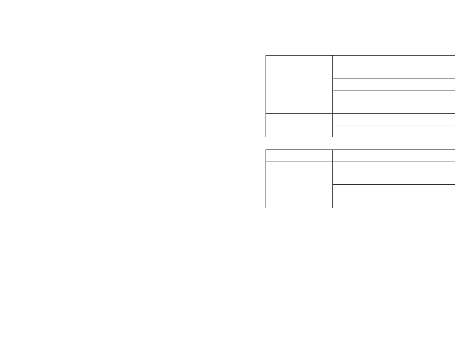
Print Head (Remote)
Standard Finish: Grained 304 Stainless Steel
Dimensions: (width x
height x depth):
Conduit Length: (128 & 256 dot): 1.0m
Control Unit
Standard Finish: Grained 304 Stainless Steel
Dimensions: (width x
length x height):
Control Panel Material: Polyester Membrane Touch Panel
(128 dot): 39.5mm x 71.5mm x 65mm
(256 dot): 59.5mm x 90mm x 90mm
(500 dot inclined): 79mm x 114mm x 187mm
(500 dot): 79mm x 170mm x 114
(500 dot only): 1.5m
(128 dot): 113mm x 295mm x 125mm
(256 dot): 113mm x 295mm x 146mm
(500 dot): 113mm x 370mm x 160mm
77144 Issue 8 August 2009 13
Page 14
PRINTER SPECIFICATION
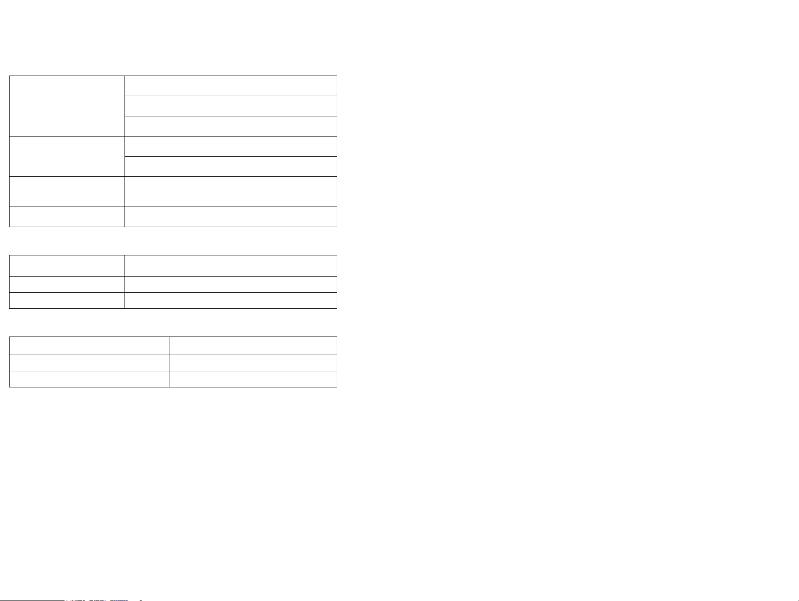
Base
Standard Finish: (200ml) Grained 304 Stainless Steel
(2 litre) Grained 304 Stainless Steel
Grained 304 Stainless Steel
Dimensions: (width x
(200ml): 152mm x 360mm x 108mm
length x height):
(2 litre): 228mm x 507mm x 139mm
Dimensions (incl. bracket):
289mm x 520mm x 252mm
(width x height x depth):
Weight (no fluids): 16.3kg
Data Input
Interface Rate
RS232: 300 - 115200 Baud Software Configurable
TCP/IP: 10BaseT
Environment
Temperature Range (working):
Humidity: 10 - 90% RH
Electrical Supply: Single Phase, 90-240V @ 50-60 Hz
+10
ºC to +40ºC (50ºF to 104ºF)
14 77144 Issue 8 August 2009
Page 15
PRINTER SPECIFICATION
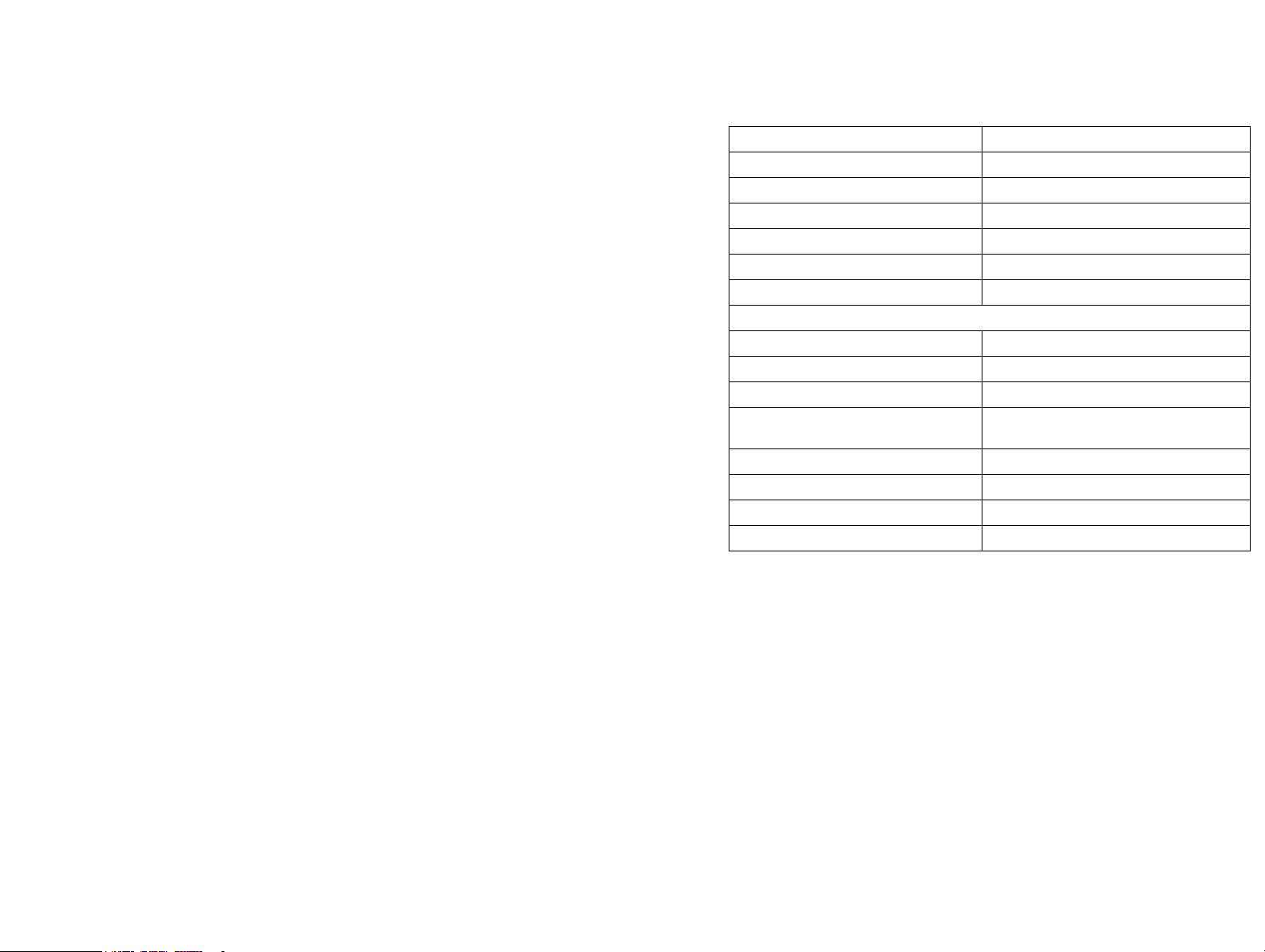
Base Unit Connectors (MHB)
Power Connector: IEC
Product Detector Connector: DIN 5-way 180
Shaft Encoder Connector: DIN 4-way
Shaft Encoder Input: PNP
RS232 Connector: 9-way D
Bottle Empty Alarm Connector: DIN 5-way 240
Ink Out Alarm Connector: DIN 5-way 240
Base and Head Connections
Product Detector Connector: DIN 5-way 180
TCP/IP Connector: RJ45
“Bottle Out” Alarm Connector: DIN 5-way 240 (2 litre base only)
Shaft Encoder Connector (via
Accessory Connection Box (ACB)): DIN 4-way
Shaft Encoder Input: PNP
RS232 Connector (via ACB) 9-way D
Ink Out Alarm Connector (via ACB) DIN 5way 240
Power Connector IEC
77144 Issue 8 August 2009 15
Page 16
BASIC OPERATIONS
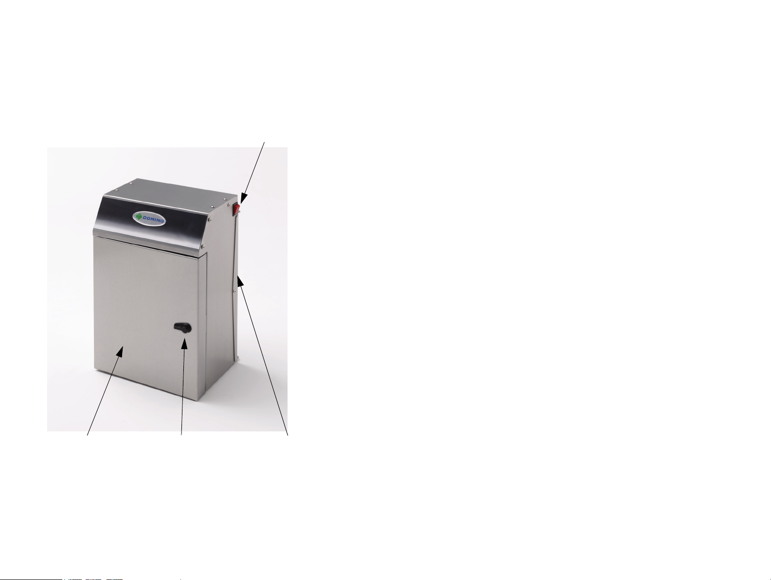
Door Latch
Power Switch
Multi-head Base Unit
Ink Bottle (behind door)
Mounting Bracket
BASIC OPERATIONS
16 77144 Issue 8 August 2009
Page 17
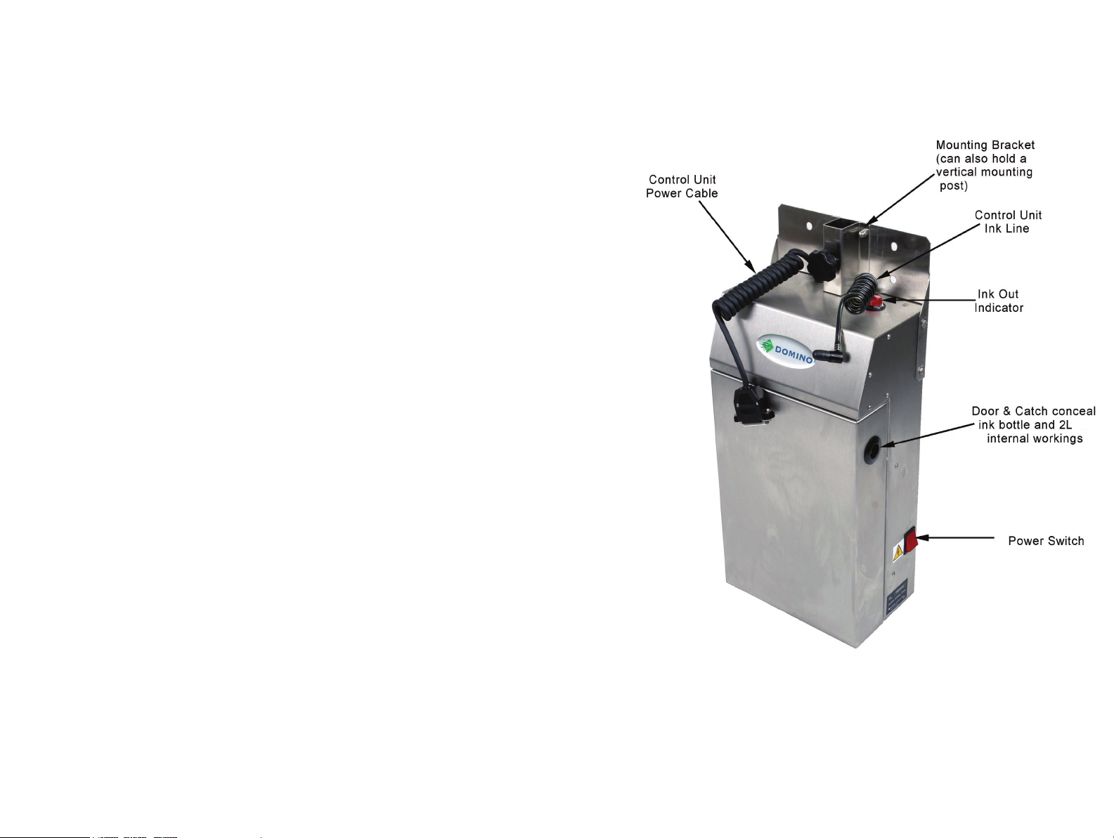
2 Litre Base Unit
BASIC OPERATIONS
77144 Issue 8 August 2009 17
Page 18
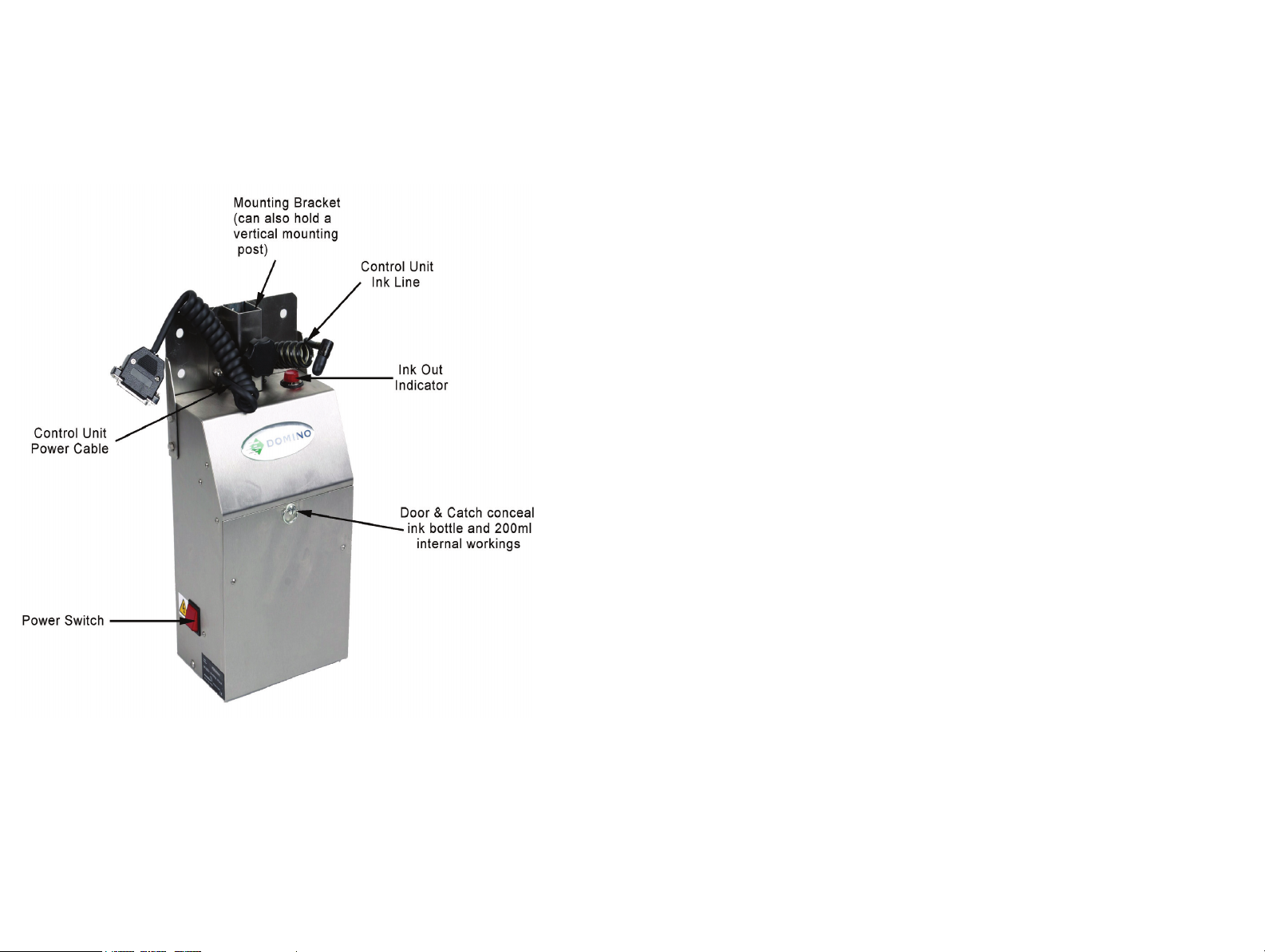
BASIC OPERATIONS
200ml Base Unit
18 77144 Issue 8 August 2009
Page 19
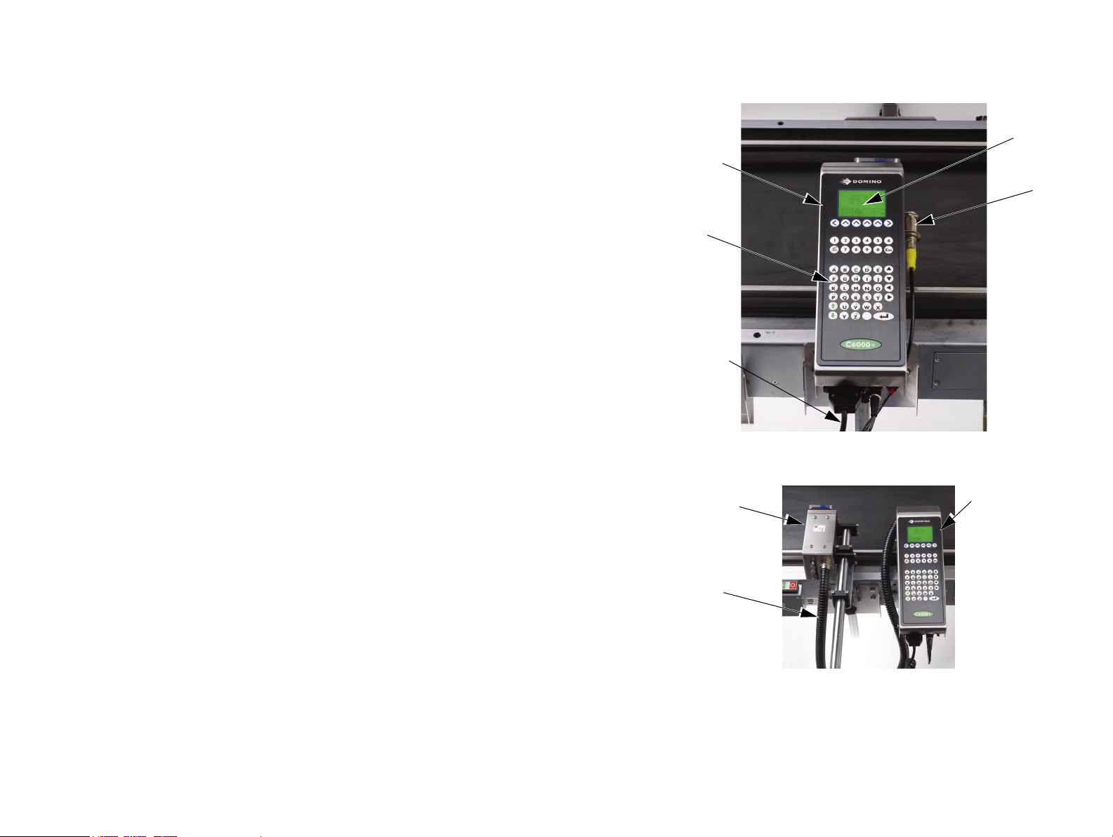
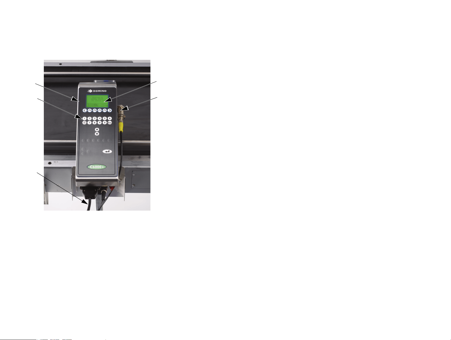
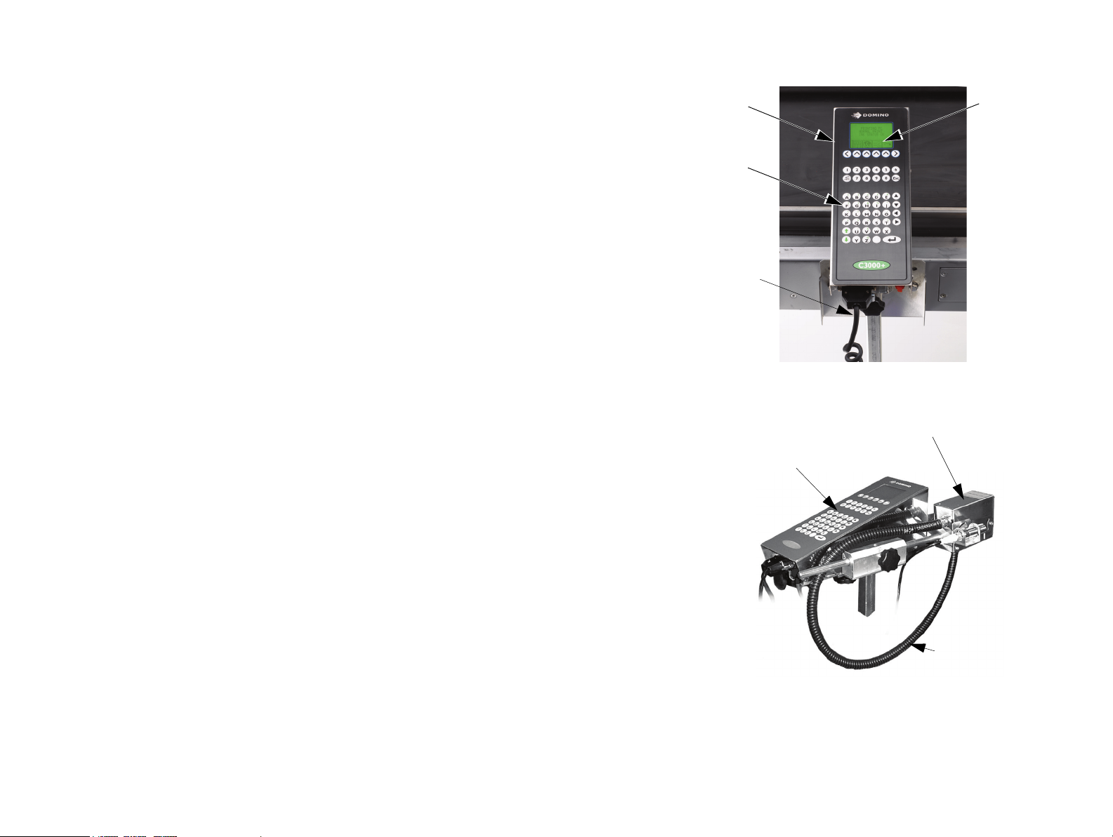
Alphanumeric
keypad
LCD display
Control unit
Control unit
power cable
C6000(i) Control Unit
C6000i Control Unit and Print Head
Conduit
Control unit
Print head
Product
Detector
BASIC OPERATIONS
77144 Issue 8 August 2009 19
Page 20
Keypad
LCD display
Control unit
Control unit
power cable
C6000MF - Control Unit
Product
Detector
BASIC OPERATIONS
20 77144 Issue 8 August 2009
Page 21
LCD display
Control unit
Control unit
power cable
C3000(X) Control Unit
C3000X Control Unit and Print Head
Conduit
Print head
Control unit
Alphanumeric
keypad
BASIC OPERATIONS
77144 Issue 8 August 2009 21
Page 22
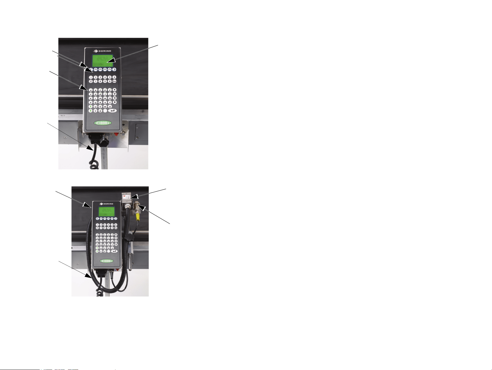
Alphanumeric
keypad
LCD display
Control unit
Control unit
power cable
C1000 (X) Control Unit
C1000X Control Unit and Print Head
Conduit
Print Head
Control unit
Product
Detector
BASIC OPERATIONS
22 77144 Issue 8 August 2009
Page 23
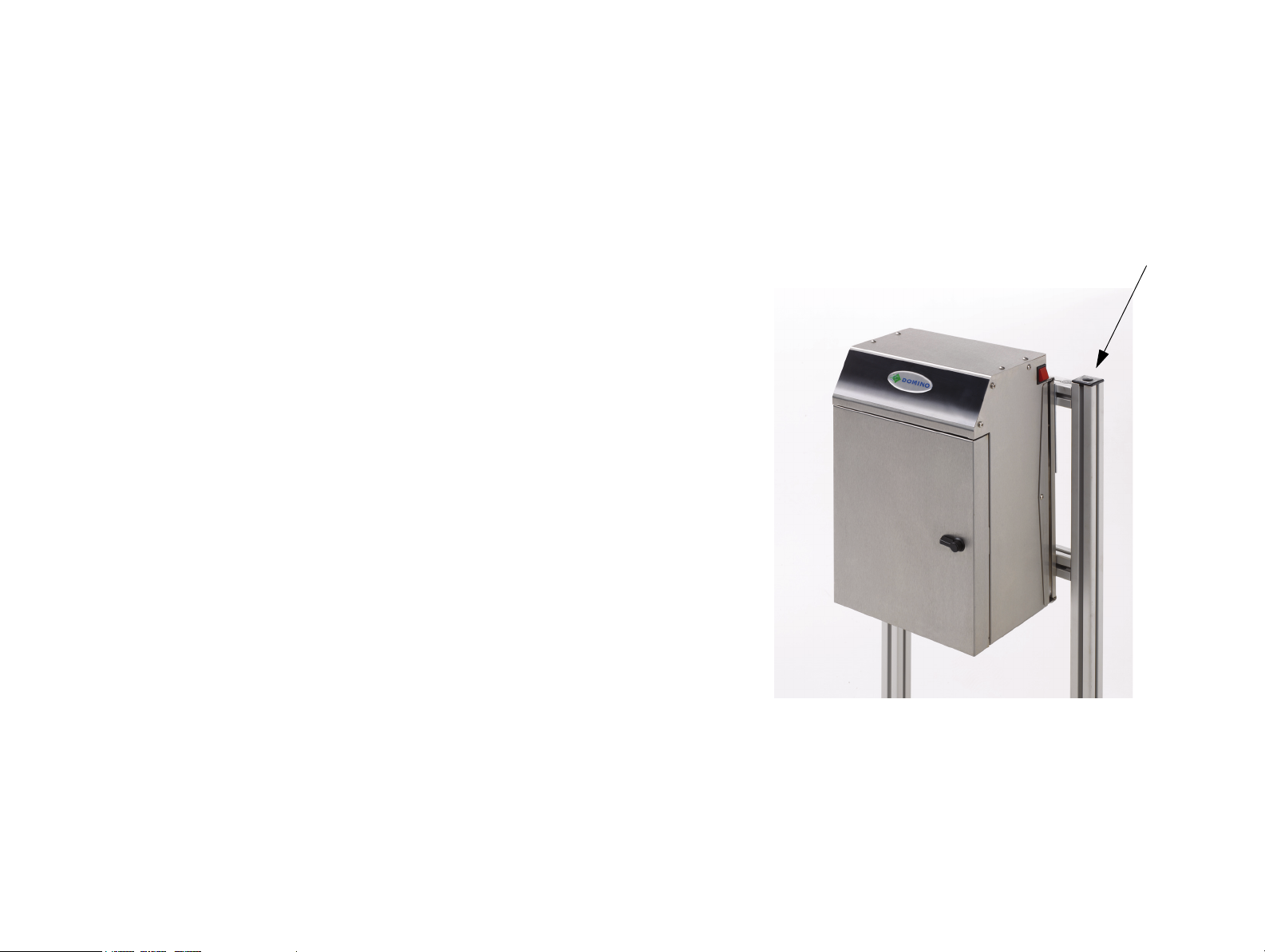
Stand
Multi-head Base Stand
BASIC OPERATIONS
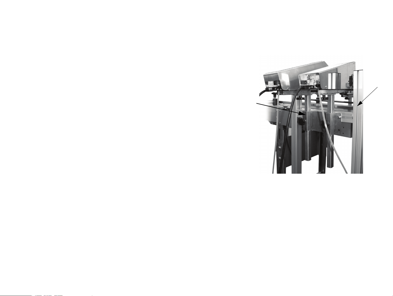
BASE UNIT MOUNTING
The base unit and control units must be mounted either on a stand or onto the
conveyor.
77144 Issue 8 August 2009 23
Page 24
BASIC OPERATIONS
Conveyor
24 77144 Issue 8 August 2009
Page 25
BASIC OPERATIONS
Dual Mounting
Bracket
Stand
DUAL MOUNTING BRACKET
Domino can supply a mounting bracket to enable two print heads to be mounted
next to each other on the stand.
77144 Issue 8 August 2009 25
Page 26
BASIC OPERATIONS
Views show C6000
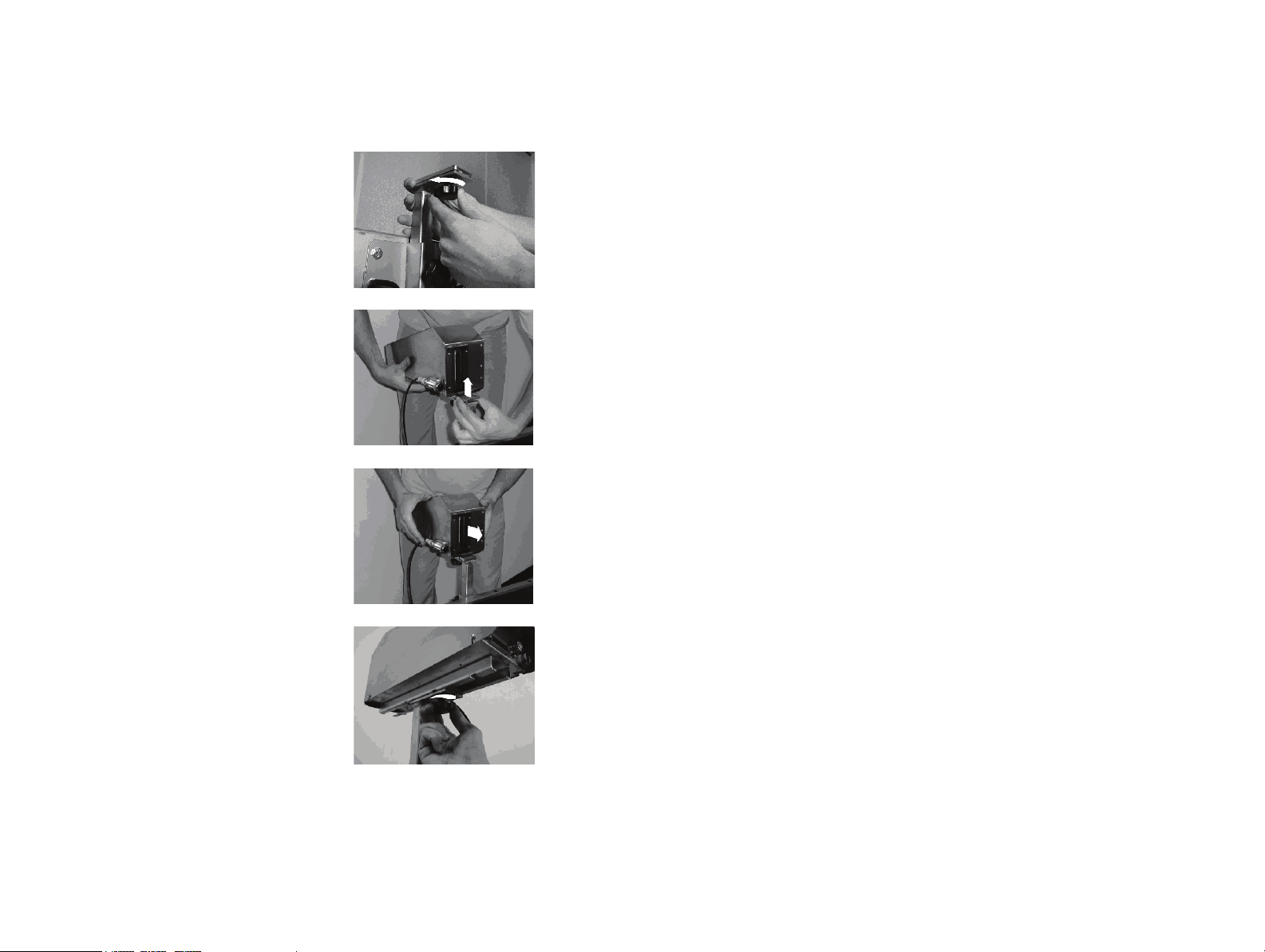
CONTROL UNIT HEAD MOUNTING
Note: It is recommended that control units are mounted on stands.
(1) To mount or dismount the control unit head,
loosen the fixing knob on the top of the
vertical mounting post.
(2) Mount the control unit by gently moving the
unit’s slide bar over the loosened clamping
plate. Ensure that the unit is well supported
during this operation.
(3) Ensure the front of the unit is facing the
conveyor belt as shown. To dismount the
unit, move the slide bar back off the
loosened clamping plate, ensuring that all
connections to the control unit are
unplugged.
(4) When the control unit has been moved to
the required position, tighten the fixing knob
at the top of the vertical mounting post.
26 77144 Issue 8 August 2009
Page 27

BASIC OPERATIONS
Base of Head and Base of
Control Unit must be at
same height when printing
vertically
CONTROL UNIT HEIGHT ADJUSTMENT
(1) The vertical mounting post on the printer
base unit can be adjusted up or down to the
required height. This operation should be
carried out with the control unit in place.
Note: Picture shown with control unit removed for
clarity.
(2) Tighten the fixing knob on the front of the
vertical column so that it is holding the
vertical mounting post securely in place.
CAUTION: The C6000i print head and
control unit must be adjusted to
the same height (bases) and must
be kept in the same environment.
Refer to page 30 for printing at
angles.
(3) To Adjust the C6000i print head, slacken the
fixing knob and adjust to the required
height.
77144 Issue 8 August 2009 27
Page 28
BASIC OPERATIONS
ROTATING THE REMOTE HEAD 90° C3000X AND C1000X ONLY
(1) To set a remote head to print down, the head
must be set to the correct height to provide
adequate tolerance for the print surface to
pass beneath it. By adjusting the length of the
bracket arm, the position of the message can
be placed accurately on the print surface.
(2) Before setting the print the head must be
rotated. The pivot point of the head will
need switching as follows; release the bracket
screws on either side of the head, ensure that
the head is held securely and the ship cap is
attached.
(3) Whilst holding the head, gently rotate it to
the position indicated.
(4) There are two sets of fixings on either side of
the head, use the ones shown.
28 77144 Issue 8 August 2009
Page 29

BASIC OPERATIONS
(5) There are two pivot points on the remote
head bracket. The top right position is for
forward and angled printing. The lower left
pivot point (indicated) is the mounting
position for printing down.
(6) Align the fixing holes and the pivot point on
the mounting bracket and refit the screws
enough to secure the head. Do not over
tighten.
(7) The sensor must also be inverted by
slackening the bottom left screw on the
sensor bracket and pushing the sensor up so
that it is facing down, ensuring that the
sensor is not triggered by the conveyor.
(8) The remote head mounting plate must be
removed and turned over to compensate for
the drop in height due to the new pivot
point. The mounting plate has a bend on
one side that increases the head height by
9mm, see step (3) on page 34. To do this,
dismount the control unit, remove and flip
the plate and remount the unit to the vertical
pillar.
77144 Issue 8 August 2009 29
Page 30
BASIC OPERATIONS
0o TO +25
o
0o TO +25
o
Controller
Print head
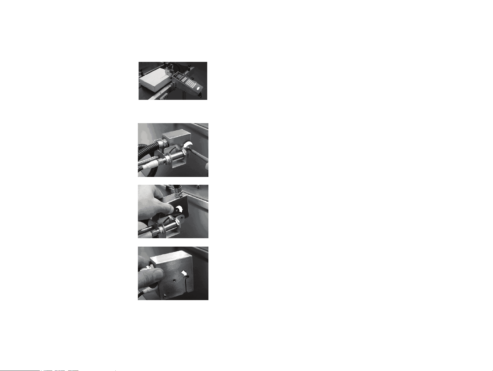
PRINTING AT ANGLES - C6000i ONLY
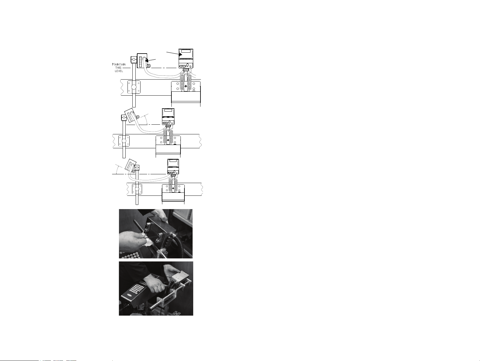
When printing horizontally, the controller
should be mounted so that the bottom
face is level with the bottom face of the
print head.
The print head can print up to a
maximum angle of 25
angle is maintained - i.e. the bottom dot
position should be higher than the bottom
of the controller face. To achieve this, the
print head should be mounted on either
side of the mounting post as follows:
Note: Before repositioning the mounting
brackets, ensure the ship cap has
been fitted and the vent valve is
shut. Ensure that the conduit
does not become twisted whilst the
print head is removed from its
mounting.
(1) Remove the bracket and print head
from the mounting post, then
remove the bracket from the print
head. Take care to retain screws
and nuts.
(2) Mount the bracket on the other
side of the print head and refit to
the mounting post. Adjust the
print head to the required angle (up
to a maximum of 25
º as long as a positive
º).
30 77144 Issue 8 August 2009
Page 31

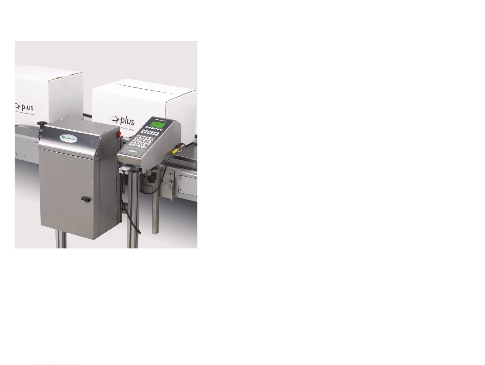
BASIC OPERATIONS
(3) After the print head has been mounted at the required angle, check the ink
flow from the controller to the print head (for initial start up it may be
useful to place tissue beneath the print head face):
(a) If the print head face is weeping:
(i) Ensure the bottom edge of the print head is the same height as
the bottom face of the controller.
(ii) Ensure that the print head angle has not exceeded 25
(iii) If the print head is still weeping, it is recommended to lower the
controller slightly whilst observing the print, until the weeping
around the lower dot position has stopped.
(b) If any dots are missing from the message (particularly at the top), it
may suggest that the controller is positioned too low in relation to the
print head. In this instance, the controller should be raised slightly
whilst observing the print until the dots re-appear.
º.
77144 Issue 8 August 2009 31
Page 32

BASIC OPERATIONS
PRINT HEAD SETUP – C6000V ONLY
The C6000v is designed only to print vertically down - for this to work there must
be a difference of 40mm ± 5mm between the bottom of the unit and the face of
the print head.
When first putting ink in the unit there are a few procedures that should be
followed to ensure that the printer works as expected and that it removes all the air
from the print head.
Setup Procedure
(1) Place a suitable ink bottle in the base and set the head to the correct height;
this is 40mm ± 5mm between the bottom of the unit and the face of the
print head. Let the unit top up with ink so that it displays ‘ink ok’.
(2) With the ink line disconnected, prime heavily until the unit displays ‘ink
low’. Turn the unit off then lift the head cover to close the AR/03 valve.
(3) Turn the unit back on. It will display ‘ink-low’. Place a container or cloth
under the print face to catch the ink. Then reconnect the ink line. This will
give a continuous ink flow from the print head. Once all the air stops
coming out of the print face, switch off the unit, lift the cover and open the
AR/03 valve.
32 77144 Issue 8 August 2009
Page 33

BASIC OPERATIONS
(4) Turn the head 90 degrees. Prime heavily, catching the ink in a suitable
container or cloth until all air is removed.
(5) Turn the head to its original vertical position.
Clean the head and test (see ‘Head Cleaning’ and ‘Priming’ on the next
page).
After the setup has been completed there are several things to look for. Below are a
few examples:
(a) Weeping: If the head is weeping then ensure that the AR/03 is open
and that all air has been removed by priming the unit. If weeping
continues then raise the print head, remembering that the maximum
height for the face of the print head should be 45mm from the bottom
of the unit.
(b) Missing channels: If a channel is missing on the test print, prime the
unit and if the problem persists lower the print head. No lower than
35mm from the bottom of the unit.
(c) Missing dots: Prime the unit. If this does not fix the problem then
clean the print head face with either WJ-910 or WJ-911.
77144 Issue 8 August 2009 33
Page 34

BASIC OPERATIONS
30°
90°
0°
30°
If using the bottom left pivot point the bend
in the bracket plate should be facing up
If using the top right pivot point the bend in
the bracket plate should be facing down.
PRINTING AT ANGLES - C3000X AND C1000X ONLY
(1) The remote head must be tilted in the
bracket arm to the required angle as follows;
slacken the two bracket fastening screws and,
using the top right pivot point, rotate the
head to the required angle. Note the
minimum and maximum angles for the top
pivot.
(2) If a smaller angle is required, the lower pivot
point must be used. When the lower pivot
point is used, the bracket mounting plate
must be turned over to compensate for the
height difference between the two pivot
points. The picture shows the different
bracket orientations.
(3) Turn the mounting plate in the direction
indicated to correspond with one of the
orientations outlined above, this will depend
on the pivot point chosen. Align the holes
then mount the control unit and the remote
head bracket to the sliding bar.
34 77144 Issue 8 August 2009
Page 35

BASIC OPERATIONS
Box
guide
rail
Buffer plateBox Guide
Ink drip tray
and ink
collection
sponge
HEAD MOUNTED BOX GUIDE
Some conveyors require extra guidance rails for the
boxes to travel on the conveyor without twisting or
hitting the control unit. The head mounted box
guide rail controls the distance between box and
print head and also corrects the misalignment of
boxes that have moved out of the correct printing
path. The box guide should only be used in
conjunction with conveyor guide rails. For
installation instructions on this box guide refer to
your local Domino office. Instructions for changing
the ink collection sponge are on page 131.
77144 Issue 8 August 2009 35
Page 36

BASIC OPERATIONS
Ship cap attachment
SHIP CAP ATTACHMENT
The ship cap is the protective cover placed
over the nozzle plate to protect it during transit
and from dust when it is not in use for more
than 24 hours.
Fit the ship cap to the print head as follows:
(1) Align the ship cap screws with the holes
either side of nozzle plate on the front
of the control unit and tighten the
screws.
(2) Screws should be tightened to the
following torque:
C1000 and C1000X - 0.34 N.m
C3000 and C3000X - 0.68 N.m
C6000, C6000MF, C6000v and C6000i - 0.34 N.m
(3) Remove the ship cap before re-starting the unit.
36 77144 Issue 8 August 2009
Page 37

BASIC OPERATIONS
Air Flow
Vent
Air Flow
Release
Locking
Screw
RELEASING THE AIR FLOW VENT
WARNING: If the printer is being run for the first time since
installation or re-mounting, the air flow vents must
be released.
There are two air flow vents in the C6000 and C6000(i), and one in the C3000
and C1000 that require releasing prior to initial power up. There is also a vent in a
2L base that needs to be released.
For the vent(s) on the header tank:
(1) Using a screwdriver, remove the four screws
securing the control unit cover.
(2) Carefully raise the control unit cover and move back
just enough to expose the header tank in the top left
corner of the control unit.
(3) The header tank air flow vent is a small plastic
valve located on the top of the header tank.
77144 Issue 8 August 2009 37
Page 38

BASIC OPERATIONS
C6000(i)
C3000, C1000, C6000v
2xvalves
Remove all securing
screws to remove the
panel cover.
Valve is located on top
of the reservoir.
(4) Using thumb and forefinger, fully undo the metal
locking ring surrounding the grey plastic air flow
release, then fully open the air flow release. When
complete, tighten the locking ring. Carefully slide
the cover back in place and secure. Take care not
to trap any wires or pipes.
For the vent in the 2 litre base unit:
(5) Open the base door and remove the panel cover.
(6) Repeat step (4) for this valve.
38 77144 Issue 8 August 2009
Page 39

BASIC OPERATIONS
REPLACING AN INK BOTTLE
CAUTION: Do not pull on the pipes in the cap, when replacing the ink bottle.
It is possible to fit either a 1 or 2 litre ink bottle.
If fitted, the beacon will flash to indicate that the
ink bottle needs replacing.
(1) If installing the printer for the first time,
there may be a piece of protective tubing
over the ends of the probes. Pull off this
piece of tubing carefully - the probes
are very sharp. Check that both O-ring
seals are present around the supply stems,
otherwise air and ink leaks may occur.
(2) Discard the transit cap from the new ink
bottle and place the bottle into the front of
the unit.
(3) Push the air and ink probes into the correct
holes in the ink bottle, puncturing the
seals.
Note: The probes have different diameters which
must be aligned correctly with the holes in
the bottle, otherwise damage can occur if
the cap is forced.
(4) Press the centre of the probe assembly
firmly to ensure that both probes have
pierced the seals.
(5) Tighten the bottle cap (hand tight only).
Arrange the air and ink tubes so that they
cannot be trapped in the door mechanism.
77144 Issue 8 August 2009 39
Page 40

BASIC OPERATIONS
200ml Base
Note: New printers are shipped with a protective tube over the septum, ensure this is
removed prior to fitting the ink bottle.
When the ink bottle is exhausted, printing will continue for a short while because
of the small reserve of ink in the header tank. When the ink supply to the header
tank runs low, the replenishment indicator on the base unit will flash. If it is empty,
replace as follows:
(1) Open the base door by pushing the catch
toward the door and twisting 90º
anticlockwise. Unscrew to remove the used
ink bottle. Ensure the use by date on the new
ink bottle has not expired and unscrew the
protective cap from the bottle non-leak top.
(2) Gently push the top of the bottle into the housing
containing the steel puncture probe.
(3) When the ink bottle is located, apply a small
downward pressure and twist the bottle in a
clockwise direction until it tightens.
(4) Close the base unit door.
Note: Discard any used or damaged ink bottles in
accordance with local waste disposal legislation. Do
not attempt to reuse used or damaged ink bottles.
40 77144 Issue 8 August 2009
Page 41

BASIC OPERATIONS
2 Litre Base
CAUTION: Do not to pull on the pipes in the cap, when replacing the ink bottle.
A warning light on the top of the base will flash to indicate that the ink bottle
needs replacing. The light will flash slowly as the ink falls below the first level
(bottle empty, up to 8hrs of printing time remaining). When the ink falls below
the second level (ink chamber empty), the warning light will flash rapidly. When
the printer screen shows Ink status out, there are 19 prints remaining before the
printer will stop.
The ink cap is attached to the inside of the base unit by its two feed pipes (air in
and ink out). Two metal probes pierce the seal in the ink bottle allowing an airtight, ink-tight seal to be formed.
(1) If installing the printer for the first time, there may
be a piece of protective tubing placed over the ends
of the probes. Pull off this piece of tubing
carefully - the probes are very sharp. Check
that both “O” ring seals are present around the
supply stems, otherwise air and ink leaks may occur.
(2) Discard the transit cap from the new ink bottle and
push the bottle into its slots in the door of the unit.
(3) Push the air and ink probes into the correct holes
in the ink bottle, puncturing the seals. Notice that
the probes have different diameters which must be
aligned correctly with the holes in the bottle,
otherwise damage will result if the cap is forced.
77144 Issue 8 August 2009 41
Page 42

BASIC OPERATIONS
(4) Press the centre of the probe assembly firmly
with the thumbs to ensure that both probes
have pierced the seals.
(5) Tighten the bottle cap (hand tight only).
Arrange the air and ink tubes so that they
cannot be trapped in the door mechanism.
42 77144 Issue 8 August 2009
Page 43

BASIC OPERATIONS
Control Unit
Connectors
RS232
Product
Detector
Shaft
Encoder
Power
Connector
Ink Out
Beacon
Bottle Out
Beacon
Base Unit
Ink Connectors
Base Unit Connectors
To control Unit
1, 2, 3 and 4
To control Unit 1, 2, 3 and 4
INTERCONNECTIONS
Base Unit
CAUTION: Ensure that Control Unit connector 1 and ink connector 1 are
connected to control unit 1 and so on.
(1) The connections on the back of the control unit are for power, 4 x Control
unit connections, 1 x product sensor, 1 x shaft encoder, 2 x beacons (1 for
bottle out, 1 for ink out) and 1 x RS232 connection, there are also 4 x ink
connections. The control unit and ink connections relate to the 4 control
units that can be connected to the base. All connections should be checked
and maintained to ensure that the unit remains in good working order.
(2) Connect the 25-way connector(s) from the
control unit(s) to the base unit.
(3) Remove the blanking plug from the ink
connectors and connect the ink tube(s)
from the control unit(s) to the base unit.
(4) If required (e.g. for downloading messages),
connect the RS232 connection. This only
communicates to head 1, see “Options” on
page 85 for communication to multiple
heads.
77144 Issue 8 August 2009 43
Page 44

BASIC OPERATIONS
(5) Connect the product sensor and shaft
encoder.
(6) If used, connect the beacon(s).
(7) Power to the base unit is supplied via the
connector on the rear and switched on via
the illuminated switch on the side.
.
44 77144 Issue 8 August 2009
Page 45

BASIC OPERATIONS
C6000(i), C6000v
C3000 & C1000
C6000(i), C6000v
C3000 & C1000
C6000(i), C6000v
C3000 & C1000
Control Units
(1) The four connections on the back of the control unit
are the power, ink, external sensor and ethernet
connections. These connections should always be
checked and maintained to ensure that the unit
remains in good working order.
(2) The black power cable, from the base unit, is connected
to the power connection port and is secured in position
by two fixing screws. To unplug the connector ensure
these screws are unfastened.
(3) To connect the ink line, use the quick release (QR)
connector on the end of the translucent plastic tube,
running from the bottom rear of the base unit. The
QR connector must be pushed into the female
connection port on the back of the control unit head
until it clicks into place.
77144 Issue 8 August 2009 45
Page 46

BASIC OPERATIONS
C6000(i), C6000v
C3000 & C1000
Sensor
Socket
Sensor
Socket
Ethernet
Connection
Ethernet
Connection
(4) To disconnect the ink line, push the locking plate on
the side of the connection port. The connector will
release with ease. The QR plug and connection port
both contain spring loaded valves that automatically
seal to prevent ink loss.
CAUTION:The ink line should always remain connected when
the printers power is on, if disconnecting the ink line ensure the
power is turned off.
(5) The power is supplied via a connection on the
bottom of the base unit. The power cable should
be connected to a mains supply.
(6)The Ethernet connection is required if
communicating using TCP/IP protocol.
(7)The Multi-head Base Unit supplies all control units
fitted, with the print-go and shaft encoder signals.
(8)On 2L and 200ml bases only. The product sensor is
required for the C6000(i), C6000v, C3000X and
C1000X which connects into the sensor 5 pin DIN
socket.
46 77144 Issue 8 August 2009
Page 47

BASIC OPERATIONS
Power
Switch
Power
Switch
2 Litre Base
200ml Base
Powering Up
When the unit is correctly connected, the power can be switched on.
WARNING: If the printer is being run for the first time since
installation or re-mounting, the air flow vents must
be released - see page 37.
Note: If connecting for the first time, it may take a few minutes for the ink to transfer
from the bottle into the chamber.
(1) To power on the printer, press the power
switch on the bottom/top right side of the
unit (as shown). This switch will illuminate
to indicate that power is on.
77144 Issue 8 August 2009 47
Page 48

BASIC OPERATIONS
PLEASE WAIT
PRINTING Name
NORMAL PRINT
INK STATUS OK
ABC
(2) The printer will power up. The LCD screen will
flash twice and the screen will prompt “Please
wait” for a short while followed by
“Initialising”.
(3) After a short wait the screen shown will be
displayed. Where “Name” is seen, the
currently selected message name is displayed.
Before proceeding to the printing stage, it is
recommended that the prime function is
carried out to prime the nozzle plate with
ink, clearing any dust from the print head.
48 77144 Issue 8 August 2009
Page 49

BASIC OPERATIONS
PRINTING TEST
NORMAL PRINT
INK STATUS OK
ABC
ABOUT TO PRIME
PRESS TO
CONFIRM
OR ESC TO RESUME
PRIMING THE PRINT HEAD(S)
It is good practice to prime the control unit(s) at least once a day. It is
recommended that this is carried out as soon as the printer has been powered up at
the beginning of a shift to prevent degradation in the print quality.
Note: To run remote units for the first time: Power up the unit until ink ok is
displayed and then disconnect the ink line. Purge the unit until the head
reports ink low. Close the vent valves in the print head and reconnect the ink
line. The base will now pump ink through the system. Turn the unit off when
a constant stream of ink is coming from the print face. Release the vent valves
and turn unit on.
CAUTION: Do not wipe across the face of the nozzle plate.
Note: Illustrations show C6000.
(1) Hold a cleaning wipe just below the base of the
nozzle plate.
(2) Press the prime key on the LCD screen.
This will purge a small amount of ink through
the nozzle plate so it is primed and ready to
print.
(3) Before any ink is expelled from the nozzle plate,
a screen prompt will appear on the LCD asking
for confirmation of the prime function. Press
enter to confirm the action.
(4) Continue holding the cleaning wipe in position.
The print head will expel a small amount of ink
whilst making a vibrating sound for
approximately five seconds. Only remove the
cleaning wipe when all the ink has been soaked
up. The control unit is now primed and ready to
print. Repeat the procedure if necessary.
77144 Issue 8 August 2009 49
Page 50

BASIC OPERATIONS
Ink
Vent
Note: In the case of persistent air in the ink system, it
is possible to intermittently plug the ink vent on
the bottom of the printer with a finger during the
prime procedure. Put finger over vent hole for
maximum 1 second only. Do not keep finger
over the ink vent for the duration of the prime
procedure.
C6000v Priming
(1) Ensure the print head face is back in its vertical position. Prime as with
other units, catching the ink in a suitable container or cloth.
(2) To remove spots of ink from the print face, use a swab and gently blot to
remove the ink off the print face.
50 77144 Issue 8 August 2009
Page 51

BASIC OPERATIONS
PRINTING TEST
NORMAL PRINT
INK STATUS OK
ABC
ABOUT TO PRIME
PRESS TO
CONFIRM
OR ESC TO RESUME
PRIMING A ROTATED HEAD - C3000X AND C1000X ONLY
When a remote head is in the printing down position, prime as follows:
CAUTION: Do not wipe across the face of the nozzle plate.
(1) Slacken the bracket screws and pull the head
back at a slight angle as shown. Hold a
cleaning wipe just below the base of the nozzle
plate as shown.
(2) Press the prime key on the LCD screen.
This will purge a small amount of ink through
the nozzle plate so it is primed and ready to
print.
(3) Before any ink is expelled from the nozzle
plate, a screen prompt will appear on the LCD
asking for confirmation of the prime function.
Press enter to confirm the action.
(4) Continue holding the cleaning wipe in
position. The print head will expel a small
amount of ink whilst making a vibrating sound
for approximately five seconds. Only remove
the cleaning wipe when all the ink has been
soaked up.
(5) Move the head back to the printing down position and tighten the bracket.
Repeat the procedure if necessary.
77144 Issue 8 August 2009 51
Page 52

BASIC OPERATIONS
AUTO PRIME
WARNING: Ensure that any purged ink is collected using a box
guide with ink drip tray and collection sponge.
Note: The Auto Prime function is controlled using Connect software for the
C6000MF. Please refer to the Connect manual.
Number of Prints
It is possible to set the printer to automatically prime the print head after a set
number of prints. The printer will expel a small amount of ink from the nozzle
plate after the prints.
Set the auto prime function as follows:
Press the Options icon and select auto prime.
Note: This function is password protected.
Enter the number of prints after which the printer will auto prime. This is up to a
maximum of 32,000 prints and 0 is disabled.
The printer will then auto prime the nozzle after this amount of prints.
Duration
It is also possible to set the duration of the purge (the length of time the purge
pump is on), this can be set between 0.08 and 9.99 seconds.
Timed
Instead, or as well as setting the number of prints, it is possible to select the time in
minutes after which the purge occurs, up to a maximum of 32,000 minutes (0 is
disabled).
Event Driven
An external source can also give the printer a signal to auto prime, this is done in
conjunction with the above settings and is set to either Enable or Disable.
52 77144 Issue 8 August 2009
Page 53

BASIC OPERATIONS
Liquid Crystal
Display Screen
(LCD)
Main Menu Bar
Horizontal Scrolling
Scroll Menu Bar
Left
Delete
Alphanumeric
Keypads
Shift Up &
Down
Four
Corresponding
Menu Bar Selection
Keys
Scroll Menu Bar
Right
Escape Current
Menu/selection
Cursor Keys
Enter (Select)
Current Settings
Space
PRINTING TEST
NORMAL PRINT
INK STATUS OK
ABC
Standard Keypad Layout
CONTROL UNIT KEYPAD LAYOUT
77144 Issue 8 August 2009 53
Page 54

Liquid Crystal
Display Screen
(LCD)
Delete
Numeric
Keypad
UpShift
Escape Current
Menu/selection
Function Keys
Enter (Select)
Current Settings
PRINTING TEST
NORMAL PRINT
INK STATUS OK
ABC
Down Shift
Point
Scroll Left/
Right
Scroll Up/
Down
MF Keypad Layout
BASIC OPERATIONS
54 77144 Issue 8 August 2009
Page 55

BASIC OPERATIONS
Menu icons
correspond
with the plain
keys directly
beneath
If there are no
icons left in the
menu bar, the
direction key
will not do
anything if
pressed
This graphic is
part of the next
icon and means
there are
further icons to
the right
Directional
menu keys will
scroll through
the icons in the
menu bar
PRINTING TEST
NORMAL PRINT
INK STATUS OK
ABC
ABC
ABC
New graphic of
partial icon
appears on the
left side of the
LCD, indicating
that menu bar
can scroll left
New Product
direction icon
appears to the
right of the
LCD
PRINTING MESSAGE1
NORMAL PRINT
INK STATUS OK
ABC
Basic Interface Controls
The main menu bar is shown above. There are never more then four icons on
display at one time. These icons correspond directly with the plain keys beneath
them. For example if the plain key on the far right is pressed the prime icon
would be selected.
If the operator presses the left arrow key nothing will happen as there are no icons
in this direction. If the right arrow key is pressed once, the menu bar will scroll
across by one icon. As a result the print which message? icon will disappear
and the product direction icon is displayed.
77144 Issue 8 August 2009 55
Page 56

BASIC OPERATIONS
Functions and Menus
When the basic operation of the control unit is understood, the operator may
commence programming instructions and commands into the printer. It is
recommended to read through the different menus and familiarise with all icons.
Note: When using the directional keys to scroll through the menu bar, if the
directional arrow key is pressed and held, then the menu will continue to scroll
until the operator releases the key or the end of the menu bar is reached.
56 77144 Issue 8 August 2009
Page 57

BASIC OPERATIONS
E
SC
BC
Keypad Functions
The control unit communicates via an array of various keypad and LCD functions.
A brief explanation of these functions is as follows.
CONTROL UNIT,
FUNCTION KEYS
The enter key is used to execute commands like
saving changes to a message or confirming the
selection of certain commands.
The escape key is used when a command or icon
that has been selected is not required or needs to be
cancelled without making further selections.
The delete key is mainly used in the message editor
to erase text, graphics or spaces. It can also be used to
delete characters when entering information into
other menus and functions.
The up shift key can be combined with delete or the
alphanumeric keys, to give greater options for these
keys. For example if used with the alphanumeric keys,
the small green character in the top right corner of the
keys are used.
Name & Description
The down shift key is combined with other keys to
give alternate options with various keys. For example,
when down shift is pressed simultaneously with a
letter key, it will create a lower case character. Rather
than the default upper case.
The cursor keys control the movement of the
flashing cursor block in various option screens, for
example when editing text or setting the clock. They
can also be combined with the shift keys in the
message editor.
The space key is used to add spaces between text and
attributes when editing or creating a new message.
77144 Issue 8 August 2009 57
Page 58

BASIC OPERATIONS
E
SC
BC
2001
Function Keys - C6000 MF Only
CONTROL UNIT,
FUNCTION KEYS
The enter key is used to execute commands like
saving changes to a message or confirming the selection
of certain commands.
The escape key is used when a command or icon that
has been selected is not required or needs to be
cancelled without making further selections.
The delete key is used to delete messages from the
memory, or editing information.
The cursor keys control the movement of the flashing
cursor block in various option screens, for example
when editing the IP address.
LCD Screen Icons - C6000 MF Only
ROOT LEVEL, MENU
BAR ICONS
Name & Description
NAME & DESCRIPTION
It is recommended that the Prime print head is
performed every time the printer is started or
when the nozzle plate requires cleaning.
Enable user password, the operator can restrict
access to the control unit by installing a numeric
user password.
Wipe completely erases the control unit memory,
this icon will delete all saved messages and
downloaded logos. The printer will revert to its
default factory settings.
External Setup, used to setup parameters of
external variables - preamble, postamble &
timeout.
Options, allows the user to enable external
settings, such as IP Address.
58 77144 Issue 8 August 2009
Page 59

BASIC OPERATIONS
Down Shift
FIPTV
C6000MFSpecial Function Keys
UpShift
Point
The following keys are used to perform specific functions, usually in conjunction
with the downshift key.
Downshift + F Fill the ink system. If ink system is already full, will report
Ink system filled
Downshift + I View the IP setting details. To change the IP address, see
below.
Downshift + P Enable/Disable the password.
T To print a test message, hold the T button in and power
the printer on.
V View current software issue details
To change the IP address, use the scroll left/right buttons to locate the Options
icon , select by pressing the button below the icon. Using the Up/Down
scroll buttons, scroll the cursor to IP Settings, press enter to select the IP setting.
Use the delete key to remove the old value and replace using the numeric keys - to
enter a decimal point, use the upshift and Point keys. Once complete, scroll to
OK and press the enter key.
77144 Issue 8 August 2009 59
Page 60

BASIC OPERATIONS
ABC
ABC
LCD Screen Icons
ROOT LEVEL, MENU
BAR ICONS
NAME & DESCRIPTION
Print which message?, select a saved message to
be printed from the control unit’s memory.
Edit or create a message?, to format a new
message, update or edit an old message.
Parameters of the message can be altered, e.g.
print speed, DPI, delay, adjusting the bar codes or
copying current message parameters as the default
settings.
Prime print head, it is recommended the prime
function is performed every time the printer is
started or any time the nozzle plate requires
cleaning.
Product direction, depending on which side of
the conveyor the printer is mounted, will
determine whether the message is printed from left
to right or right to left.
Enter new time, can be adjusted at any point.
Details of time, date, month and day can be
entered for printing.
Rollover time, the default rollover time is set to
midnight. This is when the system clock will
rollover on to a new day. The rollover function can
be changed to suit.
Enter number of shifts, the printer can keep a
track of the shifts during the running time of the
production line, this icon allows the selection of
between 1-4 different shifts.
60 77144 Issue 8 August 2009
Page 61

BASIC OPERATIONS
123
2001
ABC
V
V
ROOT LEVEL, MENU
BAR ICONS
NAME & DESCRIPTION
Box count, this icon allows the operator to record
the number of products passing on the production
line.
Choose language, allows the operator to select
from the list of operating languages.
Options screen, allows the operator to enable
external peripherals, e.g. a shaft encoder or
external photo cell.
Enable user password, the operator can restrict
access to the control unit by installing a user
password so that the settings cannot be changed.
Wipe, to completely erase the control unit
memory, this icon will delete all saved messages
and downloaded logos. The printer will revert to
its default factory settings.
Orientation, to invert and reverse the message.
The print direction is automatically changed.
Ink Cost Calculator, used to calculate the cost
and amount of ink used for a specified message.
Var ia bl es , add either a prompted or external
variable into a message.
External Setup, used to setup parameters of
external variables - preamble, postamble &
timeout.
Shaft Encoder Sensing, measures S/E pulses to
ensure not being overdriven for current DPI.
77144 Issue 8 August 2009 61
Page 62

BASIC OPERATIONS
THIS PAGE INTENTIONALLY BLANK
62 77144 Issue 8 August 2009
Page 63

Interface Map
DPI
A
ABC
A
A
30 31 1
123
Æ
Ç
Ä
â
ABCD
ABCD
ABCD
ABCD
AB
A
D
Y
H
MM
DOW
DOY
W
PRINT
MAGNIFICATION
VARIABLE
EXTERNAL
SETUP
ALTERNATIVE
FONT
ABC
ABC
123
2001
ABC
V
V
ORIENTATION
INK COST
CALCULATOR
WIPE
MEMORY
ENTER
PASSWORD
OPTION
SCREEN
SELECT A
LANGUAGE
CURRENT BOX
COUNT
ENTER NUMBER
OF SHIFTS
ROLLOVER
TIME
ENTER NEW
TIME
DIRECTION
PURGE NOZZLE
PLATE
PARAMETERS
EDIT OR
CREATE NEW
MESSAGE
PRINT WHICH
MESSAGE?
PRINT WHICH
MESSAGE?
> MESSAGE 1
MESSAGE 2
MESSAGE 3
EDIT WHICH
MESSAGE?
>MESSAGE 1
MESSAGE 2
MESSAGE 3
PHASE
ADJUST
COPY
PARAMETERS
AS DEFAULT
PICK MESSAGE
TO ADJUST
PICK CURRENT
MESSAGE
WHICH
MESSAGE?
> MESSAGE 1
MESSAGE 2
MESSAGE 3
SPEED
RESOLUTION
DELAY BAR CODE
SPACING
BAR
WIDTH
V
V
VARIABLE
LOGO LIST
BAR CODE
CHARACTER
MAP
COUNTING
REAL TIME
COMMANDS
SELL BY
DATE
SELECT
FONT SIZE
EDIT
EIGHTH
HEIGHT
QUARTER
HEIGHT
HALF
HEIGHT
FULL
HEIGHT
OPTIONS
MENU
DAY MONTH
YEAR
D
Y
DAY MONTH
YEAR
OPTIONS
MENU
D
Y
DAY MONTH
YEAR
DAY OF
WEEK
DAY OF
YEAR
WEEK
SHAFT ENCODER
SENSING
BASIC OPERATIONS
77144 Issue 8 August 2009 63
Page 64

BASIC OPERATIONS
THIS PAGE INTENTIONALLY BLANK
64 77144 Issue 8 August 2009
Page 65

BASIC OPERATIONS
Bottom
of
nozzle
plate
SETTING A PRINT JOB
When setting a print job, it is good practice to prepare the site - ensuring that the
printer and conveyor are set correctly. The following steps outline this set up
procedure:
A Multi-head Base Unit should be mounted in a suitable position to enable the
control units to be mounted within 3 metres of the base. Each print head can be
set up as follows:
(1) Calculate exactly where the message is to be
printed on the surface of the substrate. For
this example, the message is printed on the
box.
(2) To calculate how high to set the print head,
place the print surface (box) onto the
conveyor next to the control unit, measure
from the lowest point of the intended
message to the conveyor surface. This
measurement will be where the bottom of
the nozzle plate will need to be set.
(3) Measure from the bottom of the nozzle plate
to the conveyor. Ensure this measurement
matches the distance from step (2). If not,
loosen the black plastic fixing knob on the
front of the base unit and adjust to the
desired height.
77144 Issue 8 August 2009 65
Page 66

BASIC OPERATIONS
Fixing knob
(4) When the control unit is at the required
height, tighten the fixing knob.
(5) When the vertical height of the unit is set,
the conveyor mounted guide rails should be
positioned so the box is not too far from the
print head. At this point the distance from
the control unit front to the box can be
approximated. It will be adjusted more
accurately in the next step.
(6) To accurately adjust the horizontal distance
between the box and the unit, loosen the
black plastic fixing knob beneath the control
unit, then move the unit forward until it sits
flush against the surface of the box. Do not
press too hard, the surfaces should be as
close as possible without touching.
(7) When the horizontal distance is set, ensure
there is adequate tolerance for the box to
move past the print head without getting
stuck or misaligned. If not, move the control
unit back very slightly.
(8) Repeat steps (1) to (7) above for all control
units (print heads).
66 77144 Issue 8 August 2009
Page 67

BASIC OPERATIONS
A
(9) When the set up is complete, the printer
should be switched on and tested. Run a test
box on the conveyor, past the print head(s) to
check that the message is printing in the
required location. The vertical and
horizontal adjustments may need to be fine
tuned. If the message is printing too close to
the edge of the box then this must be
adjusted using the delay function . See
Adjusting Parameters for further
information, for the C6000MF printer this is
done via the Connect software, refer to the
Connect manual.
77144 Issue 8 August 2009 67
Page 68

BASIC OPERATIONS
PRINTING A DEFAULT TEST MESSAGE
The printer can print a test message to check print quality, as follows:
(1) Turn off the printer.
(2) Hold down the letter ‘T’ button and switch on the printer.
(3) Keep the ‘T’ button depressed until the screen shows that initialising is
complete. During this time the test message will be loaded.
(4) Print the test message by passing a piece of card in front of the product
detector and printer. Check the test message is clear and complete. If any
nozzles appear blocked, refer to the section “Priming the print head”.
It is also possible to print the test message by selecting the message called “TEST”
from the print which message menu.
68 77144 Issue 8 August 2009
Page 69

BASIC OPERATIONS
ABC
LOAD MESSAGE
LOAD MSG TO MEMORY
DELETE MSG FROM MEMORY
ABC
PRINT WHICH MESSAGE
> ALAN
BEST
DATE
CRISPS
PRINT WHICH MESSAGE
DATE
EXPIRY
s*
> SCREWS
SWAP
TINNED
PRINTING A SAVED MESSAGE
The printer can quickly switch between saved messages.
The message store can be viewed and messages uploaded by selecting the print
which message? icon. To use this function:
(1) Select the print which message?
icon on the main menu bar. The following
sub menu screen is displayed.
(2) The menu options can be selected using
the cursor keys to scroll the selection arrow
up or down and the enter key.
Load Message: The screen will display
the saved messages list in alphanumeric
order. The list can be scrolled up or down
using the cursor keys.
Alternatively, if the list is long, to save
scrolling through all the messages with the
up down cursors, the operator can press the
first letter of a message name. This will
cause the > cursor to move directly to the
first message beginning with that letter or
number (s in this example), this character is
retained so the second character entered
searches on the second character of the
message names,i.e.
SCREWS S would point to SCREWS
SWAP W would point to SWAP.
The search string is cleared if the UP or DOWN arrows are pressed. When
on the correct message, press enter to confirm the upload.
77144 Issue 8 August 2009 69
Page 70

BASIC OPERATIONS
PRINTING SCREW
NORMAL PRINT
INK STATUS OK
ABC
(3) When enter is pressed, the screen will return
to the main menu and the appropriate
message name will appear on the screen
prompt to confirm that it has been uploaded.
The message is now ready to be printed.
Load msg to memory: This also displays the saved messages in
alphanumeric order but, on selection it loads the message into memory to
allow for fast message changeover. It does not affect the currently printing
message. These messages in memory are selected from an external source.
Delete msg from memory: This displays the current list of messages
that are loaded into memory and enables the user to delete messages from
the memory list. This does not delete the message from the printer.
70 77144 Issue 8 August 2009
Page 71

BASIC OPERATIONS
ERASE
YOU ARE ABOUT TO
ERASE MESSAGE
SCREW
PLEASE CONFIRM
BC
DELETING A SAVED MESSAGE
To delete a message, select the edit which
message? menu, scroll the message list as
described in step (2) on page 69 and select a saved
message to erase. When the
appropriate message press the delete key and
the screen prompt opposite is displayed. Press
enter to confirm, or escape to undo, this action.
Note: It is not possible to delete the currently
printing message.
> cursor is on the
77144 Issue 8 August 2009 71
Page 72

PROGRAMMING THE PRINTER
Press the corresponding key to select the function
PRINTING MESSAGE1
NORMAL PRINT
INK STATUS OK
Press right directional key until the menu bar starts to scroll
123
> ENGLISH
FRENCH
ITALIAN
PORTUGUESE
SPANISH
GERMAN
DUTCH
PROGRAMMING THE PRINTER
SELECTING A LANGUAGE
The printer can communicate with the operator in one of several resident
languages. Select a new operating language as follows:
(1) Scroll through the menu bar using the right directional key and select the
global map icon. The arrow key can be pressed continuously to scroll
through the menu quicker.
(2) When selected, a list of languages will appear
on the LCD, use the up and down cursor
keys to scroll through the list.
(3) When the appropriate language has been
selected, press the enter key to complete the
command. All the menus and options will
then operate in the chosen language.
72 77144 Issue 8 August 2009
Page 73

PROGRAMMING THE PRINTER
ENTER NEW TIME....
HR:MI DT/MO/YR D
15 : 28 10/11/00 5
SETTING THE CLOCK
This function determines the clock time used to run some of its real time
functions, e.g. shift codes, sell by dates and date/time prints.
Note: When the current time is set, it continues to operate even when the control unit
has been switched off. The only time the clock will need to be reset is if the
control unit’s memory has been wiped or if adjustments for daylight saving are
made.
The time, date and day are held in the systems
memory in the following format:
The top line is a key for the current format the
bottom contains the time/date/day data.
HR:MI is the current time in hours and minutes,
displayed in 24 hour format. In the example, the
clock reads 15:28 (3:28pm).
DT/MO/YR is the date/month/year. The
example, reads 10/11/00 (10th of November 2000).
D is the day of week. The printer works on 7 day
cycle, as a default, Monday is day 1. So Monday = 1, Tuesday = 2 Wednesday = 3,
etc. Therefore, in the example above day 5 would be Friday.
When inputting the year format, it should be entered as a two unit figure. For
example to enter 2000 as the year, enter 00 as the value. 2001, 2002, 2003 would
be 01, 02, 03, etc.
77144 Issue 8 August 2009 73
Page 74

PROGRAMMING THE PRINTER
Press the corresponding key to select the function
PRINTING MESSAGE1
NORMAL PRINT
INK STATUS OK
Press right directional key until the menu bar starts to scroll
123
CLOCK OPTIONS
> FIRST WOY
TIME
HR:MI DT/MO/YR D
5 : 28 10/12/99 5
Flashing block cursor can scroll
across time/date/day format
enabling operator to edit the
clock time.
Amend the clock function, as follows:
(1) Scroll through the menu bar functions and select the set clock icon.
(2) The Clock Options submenu is displayed.
Select the time option by using the up down
cursor keys and press enter.
(3) A flashing cursor block at the beginning of
the hours format can be moved left or right
by pressing the cursor arrows on the key pad.
(4) To re-adjust any of the values, place the
cursor over the character to be adjusted and
overtype the new value, when all changes are
completed press enter.
Note: Values that are outside the parameters of the 24 hour clock or calendar month,
74 77144 Issue 8 August 2009
are not accepted.
Page 75

PROGRAMMING THE PRINTER
Press the corresponding key to select the function
PRINTING MESSAGE1
NORMAL PRINT
INK STATUS OK
Press right directional key until the menu bar starts to scroll
123
ROLLOVER TIME
0:00
ROLLOVER TIME
The default working day ends and starts at midnight. This is when the control unit
will rollover to the next working day. This value can be adjusted as follows:
(1) Scroll through the main menu bar icons using the directional arrow keys
and select the rollover icon.
(2) When the icon has been selected, the following will be displayed
The flashing cursor block on the first character can
be moved using the left and right cursor arrows.
Move the cursor over the character to be changed
and overtype with the required rollover time, e.g.
06:00 if six AM is the required rollover time. Press
enter to confirm the changes.
77144 Issue 8 August 2009 75
Page 76

PROGRAMMING THE PRINTER
Press the corresponding key to select the function
PRINTING MESSAGE1
NORMAL PRINT
INK STATUS OK
123
ENTER NUMBER OF
SHIFTS 2, 3 OR 4
SHIFT CODES
A 00:00
A 00:00
A 00:00
Default shift code screen
ENTER NUMBER OF SHIFTS
Up to four production shifts can be programmed, and can be given code letters,
for example shifts A, B, C, D.
These shift codes are then split into the working hours of the production line. The
printer can be set to print out the shift automatically. See also formatting messages
on page 88. To enable the print out of different shifts, the times and shift codes
must be programmed. Enter the shift codes and times as follows:
(1) Scroll through the main menu bar on the LCD with the directional arrow
keys and select the shift code icon
(2) A prompt asking how many shifts are
required is displayed, in this case select 3,
press enter.
(3) A flashing cursor block will be seen at the
top left of the screen under the A character.
Decide which code letters are to be
designated to the shifts. For this example there
are 3 shifts
76 77144 Issue 8 August 2009
Page 77

PROGRAMMING THE PRINTER
SHIFT CODES
A 06:00
B 10:00
C 14:00
Newly entered shift codes
(4) Using the four cursor keys, scroll
around the shift code screen over-typing the
default letters. In this example, shift A starts
at 6am and finishes at 10am. Shift B starts at
10am and finishes at 2pm. Shift C, the final
shift, starts at 2pm and finishes at 6am. Press
the enter key to save the shift codes and
times.
77144 Issue 8 August 2009 77
Page 78

PROGRAMMING THE PRINTER
123
Press right
hand
directional key
until the menu
bar starts to
scroll
Press the
corresponding
key to select
the function
PRINTING MESSAGE1
NORMAL PRINT
INK STATUS OK
123
CURRENT BOX COUNT IS
99
DO YOU WISH TO
ZERO THIS VALUE
E
SC
123
CURRENT BOX COUNT IS
99
DO YOU WISH TO
ZERO THIS VALUE
PRESS TO CONFIRM
OR ESC TO RESUME
CHECKING CURRENT BOX COUNT
The printer is capable of counting the number of boxes that have passed the sensor.
The box count function can be zeroed at any point and will count in single
increments from zero. Check the box count as follows:
(1) Scroll through the main menu bar on the LCD with the directional arrow
keys and select the current box count icon.
(2) The current box count figure will be
displayed, in this example 99. Below the box
count number is “Do you wish to zero this
value?” If the value needs to be reset back to
zero, press the enter key. If the current
value is still required, press escape to return to the main menu.
Note: It is possible to print box counts and pallet counts. These functions are set up
under the
counting
icon which is located under the
edit which message?
menu.
(3) On pressing enter, the following screen is
displayed, press enter to zero the box count
or press Esc to resume the count.
78 77144 Issue 8 August 2009
Page 79

PROGRAMMING THE PRINTER
ENTER PASSWORD
2001
ALL MESSAGES
WILL BE LOST
PRESS TO CONFIRM
OR ESC TO RESUME
E
SC
PRINTING TEST
NORMAL PRINT
INK STATUS OK
ABC
ERASING THE CONTROL UNIT MEMORY
To erase the control unit memory, follow the steps below:
CAUTION:
(1) Enter the clear all menu, for extra
security, a screen will prompt for the re-entry
of the user password (numeric only for
C6000MF). Once the password has been
entered, press the enter key to confirm.
(2) Press enter to confirm or escape to
return to the main menu.
After the memory wipe has commenced the
screen will indicate that the system is
initialising. After a few seconds the memory
will be reset to the initial factory settings.
(3) The screen will indicate that the test message
is ready to print. For new C6000MF
printers this will be the default message.
Do not
use this function unless the whole control unit memory
needs to be wiped. All saved messages, logos and saved settings will
be wiped and replaced with the default settings.
77144 Issue 8 August 2009 79
Page 80

PROGRAMMING THE PRINTER
ABC
PRODUCT DIRECTION
PRODUCT DIRECTION
When the direction of the conveyor belt is running from left to right then
product direction function will need to be altered as shown above
PRINT DIRECTION
The print direction default is from right to left.
Depending on which side of the conveyor each
control unit is mounted, will dictate the direction
that the print surface is moving and could change to
left to right, causing the message to be printed in reverse.
If required, select the print direction icon for the affected control unit(s).
The sample screen below will be displayed. The animated directional arrow
indicates the direction of the print. If the direction needs to be altered then press
the right hand directional key. When pressed, the animated arrow will change
direction. Press enter to confirm the changes. The screen will change to show
“INITIALISING” then returns to the main screen.
80 77144 Issue 8 August 2009
Page 81

MESSAGE ORIENTATION
ABC
123
MESSAGE ORIENTATION
INK
>VOLUME(ML) : 1000
PRICE : 278.00
DOT VOLUME : 82
OK
COST (1) : 0.003283
COST (1000) : 3.283024
PRINTS : 84679
PROGRAMMING THE PRINTER
ORIENTATION
Orientation allows the operator to invert and reverse
a message.
The up and down cursor keys are used to control
the orientation of the message. The small ABC/123
graphic shows the orientation selected, once
selected press enter to confirm. The LCD will
display that the unit is initialising the changes, the
main display will show the words “Inverted Print”
instead of the usual “Normal Print”.
INK COST CALCULATOR
This function calculates the cost and amount of ink
used for a selected message. It will also estimate the
amount of prints achievable for the given quantity
of ink.
Enter in the volume of ink purchased (e.g. 1000ml)
and the price paid (example here 278.00), then dot
volume (e.g., 82pl).
Select the message from the list shown and press
Enter, the screen will change to show the cost of ink
for one print of the selected message, the cost for
1000 prints and the amount of prints for the
quantity of ink.
Note: This is an indication only and does not take
into consideration ink used for priming.
77144 Issue 8 August 2009 81
Page 82

PROGRAMMING THE PRINTER
PROMPTED VARIABLE
>NAME:
LENGTH:
PROMPT:
V
V
Boxes remaining : [ }
EXTERNAL VARIABLE
>NAME:
LENGTH:
OFFSET:
VV
VARIABLES
This function allows the insertion of a variable into a message. There are two types
of variable; prompted and external.
Prompted Variable
A prompted variable is inserted into a message and will prompt the operator for
information when that message is selected for print.
Enter a prompted variable as follows:
Select the variable Icon from the main menu,
then select new and press enter. Select Prompted
Va r i a bl e .
On this screen, enter the name required for the
variable, the number of characters for the
information required and the prompt required, e.g. “enter number of boxes left.”
Therefore, if a prompted variable is setup with
Name: “boxes”, Length: “3” and Prompt: “Boxes
remaining”, if this prompt is inserted into a message,
when the message is selected for printing, the
prompt will appear, the user can then enter the
number of boxes, up to 999.
External Variable
A variable can also be inserted into a message from an external source, i.e. a check
weigher, bar code scanner, etc.
Note: This information has to be sent to the printer prior to the print.
Enter an external variable as follows:
Select the Variable icon from the main menu,
then select new and press enter. Select External
Va r i a bl e .
On this screen, enter the name required for the
variable, the number of characters for the
information, the offset - this is the amount of
characters to offset by, e.g.
Information string is 12345abcde, if a length of 2 and an offset of 5 is entered then
the variable information would be ab, as the offset ignores the first 5 characters and
the length is 2.
Note: The External Var Params must be configured via External Setup, see page 83
82 77144 Issue 8 August 2009
Page 83

PROGRAMMING THE PRINTER
EXTERNAL VAR PARAMS
>PREAMBLE:
POSTAMBLE:
TIMEOUT:
ENABLE:
PORT:
PORT NUMBER:
OK
External Setup
Note: External setup is password protected.
When using external variables, it is necessary to set the parameters which enable
the printer to use the correct part of the information.
Set these parameters as follows:
Select External Setup Icon from the main
menu. Select External Var Params and press enter.
Preamble is the character required to indicate the
start of the information, e.g. <STX>.
Postamble is the character required to indicate the
end of the information, e.g. <ETX>.
Timeout is the number of characters after which
the printer will stop looking for a postamble. After
this, the information will have to be re-sent.
Enable must be set to TRUE to communicate
externally. If set to FALSE, it will only communicate using the C-Series protocol
and no variables can be acquired.
Port can be set to either TCP/IP or RS232. To use this, Enable must be set to
Tr ue .
Port number greater than 3001 to avoid conflict with Connect. This allows
Connect and another device to communicate with printer over TCP/IP. See
“Options” on page 85 for backward compatibility.
The unused port can still be used to communicate with either Apprentice or
Connect by selecting Enable as True and Port as RS232, this will enable external
data to enter via the RS232 port leaving communications with Connect or
Apprentice via TCP/IP. It is also possible to communicate to Apprentice via the
RS232 (Connect cannot communicate via RS232) by setting the port to TCP/IP,
this means that external data is via TCP/IP and communications to Apprentice is
via RS232.
77144 Issue 8 August 2009 83
Page 84

PROGRAMMING THE PRINTER
SERIAL PORT SETTINGS
> BAUD RATE:
BITS PER BYTE:
STOP BIT:
PARITY:
OK
The Serial port settings can also be set within the
External Setup menu. To do this, select Serial Port
Settings.
84 77144 Issue 8 August 2009
Page 85

PROGRAMMING THE PRINTER
OPTIONS
Message Revert
When printing a random system - where an external device selects the message
e.g. bar code scanner, PC, etc. - the revert message can be set so that a default
message is selected and printed when the external device does not select the
message.
The revert message can be selected from a list that is displayed when ‘Revert Back’
is enabled.
Communications
This takes you to a sub menu that gives the user the following options:
Action Comms
Normally enabled. When disabled the printer will not respond to control
characters from an external source.
Echo Data
Normally disabled. When enabled using the Multi-head Base control characters
are echoed out of the serial port.
Satellite Mode
If enabled allows the controller to change a message on another printer through
the serial link. Multi-head Base only.
Switches
This takes the user to a sub menu:
Shaft Encoder
A shaft encoder can be fitted to a production line, it’s rotation follows the speed of
the line, ensuring that the print speed changes accordingly.
For a Multi-head Base, the shaft encoder is plugged into the rear of the base unit
where the signal is then sent to all control units. For a 2 Litre or 200ml Base the
Shaft Encoder is plugged into the ACB.
At each control unit, the shaft encoder is enabled via the Options menu. To set the
printer to communicate with a shaft encoder, select the Options menu and
select Shaft Encoder. Toggle between Enabled and Disabled using the cursor keys.
77144 Issue 8 August 2009 85
Page 86

PROGRAMMING THE PRINTER
SPEED TEST
ENSURE SHAFT ENCODER
IS CONNECTED AND
SPINNING
PRESS ANY KEY
TO CONTINUE
Shaft Encoder Test
(1) To check if shaft encoder is
overdriven. When a key is pressed this will
cause the printer to count pulses for a given
time.
CAUTION: DO NOT trigger the photocell
during this test.
The printer will then respond if the
conveyor speed is ok or not, it will also
respond if no pulses were received.
Screen Saver
This function, when enabled, will automatically turn the display backlight off
when the printer is not in use.
To enable the screen saver, select the Options menu and select Screen Saver.
Toggle between Enabled and Disabled using the cursor keys.
Acknowledgement
This take you to a sub menu:
Last Raster RS232 The printer will send an acknowledge character to an
RS232 device when the last raster has been printed.
Last Raster TCP/IP In the same way as the Last Raster RS232, the printer will
send an acknowledgement character to an ethernet device when the last raster has
been printed.
New Data RS232 The printer will send an acknowledge character when the
system is ready to receive fresh data from an RS232 device.
New Data TCP/IP In the same way as the New Data RS232, the printer will
send an acknowledge character when it is ready to receive fresh data.
Record Change
The unit records each piece of changing information of the currently printing
message to a file that can be retrieved using Connect. It records the time and date,
the action and all the changing information.
Bottle Out
Used with the Multi-head Base only this will allow the bottle out to be
communicated to Connect.
86 77144 Issue 8 August 2009
Page 87

PROGRAMMING THE PRINTER
Extra Port
Normally enabled. If disabled removes the port number option from external
variable setup and fixes this to 3001. Only needed for backward compatibility.
Retrieve Mode
This is normally disabled. When enabled changes the functionality of the print
which message icon. See Connect Manual for more details.
Sensor
A sensor can be fitted to the production line to give a print-go signal when a
product passes in front of the sensor.
The recommended method for using a sensor to detect products with the Multihead Base is a single sensor plugged into the base unit. The signal is then sent to
all the control units attached. Alternatively, a sensor can be plugged into each of
the control units.
CAUTION: For Multi-head Base - do not plug a sensor into both the base and
the control unit(s) otherwise it will cause the units to print incorrectly.
Notes: (1) For the Multi-head Base, this must be set to Enabled (for external).
(2) It is not necessary to select the photocell option for the C6000 range of control
units.
Auto Prime
It is possible to set the printer to automatically prime the print head after a set
number of prints. The printer will expel a small amount of ink from the nozzle
plate after the prints.
See page 52 for further details of the Auto Prime function.
IP Settings
Note: This menu is password protected.
The IP Settings menu provides network information for the printer, such as IP
Address, Subnet Mask and Gateway.
77144 Issue 8 August 2009 87
Page 88

FORMATTING MESSAGES
ZERO WITHOUT SLASH
PRESS ANY KEY
TO CONTINUE
ZERO WITH SLASH
PRESS ANY KEY
TO CONTINUE
FORMATTING MESSAGES
CREATING A MESSAGE
A “message” is a line or lines of text, bar codes and graphics (“logos”) that are
printed to produce information on the substrate.
Messages can be saved into the memory and will remain even when the power is
removed. These messages can be edited and updated at any time or erased if no
longer required.
Zero characters can be toggled to print as 0 or ∅ (with a slash). Press upshift and
0 to display the following message (depending on which 0 state the printer is
currently set):
Press upshift and 0 to toggle again.
88 77144 Issue 8 August 2009
Page 89

FORMATTING MESSAGES
Press the corresponding key
PRINTING MESSAGE1
NORMAL PRINT
INK STATUS OK
ABC
EDIT WHICH MESSAGE?
>new
Flashing cursor
Sub menu function icons
BLANK MESSAGE
1.
2.
3.
4.
ABC
A
A
30 31 1
(1) When creating a new message, select the edit which message? icon .
(2) The saved messages screen will be displayed.
Since there are no messages currently saved,
the only option available is the create new
message option, press enter to select.
(3) The screen will prompt as shown below.
Note: It is always worthwhile creating a back-up reference of all messages on paper.
There is space provided at the back of this manual to record message names and
contents.
77144 Issue 8 August 2009 89
Page 90

FORMATTING MESSAGES
ABC
A
A
30 31 1
123
Æ
Ç
Ä
â
Edit Which Message? Sub-Menus
The text and attribute function icons located under the edit which message?
icon are shown below. The operator should familiarise themselves with these
icons to understand the message editing and creation capabilities available.
EDIT WHICH
MESSAGE?
SUB–MENU ICON
Edit an Item, to edit the parameters of a bar code, the
name of a logo or variable information (e.g. sell by dates),
select the edit function while the cursor is at the front of the
field.
Select a font, the operator must select which font size is
required for different parts of the message, if not selected the
default is automatically entered. There are four different
font sizes, full, half, quarter and the default eighth.
Sell by date, when a sell by date is required it can be
entered using the sell by date icon.
Real time commands, if times, dates and shift codes are
required in the message, this can be done using real time
commands and represented as normal text or coded for
confidentiality.
Function & Description
Counting, if a box count is to be entered into the message
then this can be done incrementally or decrementally. There
is also the option of including a pallet count. Only one
incremental, decremental and pallet count per message.
Character map, most alternative characters are available
under the character map icon.
Bar code, a list of ten different bar code types are available,
directly from the control unit memory. The bar code
horizontal scale and raster size can be controlled via the
control unit using the parameters function.
Logo list, logos can be stored in the logo store and can be
accessed and inserted in any message via this icon. Any logo
inserted via the control unit will always use the full print
height.
90 77144 Issue 8 August 2009
Page 91

FORMATTING MESSAGES
V
V
Va ri ab l e s, this allows the insertion of variable information
into a message. These can be either prompted or external.
Prompted will prompt the user to enter information and
external will read information from an external source, i.e
bar code scanner.
Alternative Font, an alternative font can be used in
message areas such as sell by dates and shift codes. Refer to
the Connect manual for further information on
downloading an alternative font.
Data matrix Code, if a data matrix code is required in the
message, it can be entered by using this icon. The height
and width of the code is also set within this command.
QR Code, if a QR code is required in the message, it can
be entered by using this icon. All functions relating to this
code are entered using this command.
Select Alternative Font
It is possible to download an alternative font (via external software). This can then
be used in messages for the following:
• Sell by Alpha Months, Days and Hours
• Shift Codes
For more information on downloading an alternative font, contact Domino or
refer to the Connect User Guide.
To use the alternative font, in the edit/create new message screen, scroll to the
icon and select. The icon should now be displayed in the top right hand
corner to indicate the alternative font is now enabled. Any text entered in will
now use the alternative font.
To turn the alternative font off and return to the default font, scroll to the
icon and press. The icon will no longer be displayed. Toggle between default and
alternative fonts to design the required message.
Using the alternative font it is possible to print a message containing two languages
e.g. English and Arabic.
77144 Issue 8 August 2009 91
Page 92

FORMATTING MESSAGES
A
A
A
A
A
A
A
A
A
A
A
A
A
A
A
Full height
Half height
Quarter height
Eighth height
(default text)
Not to scale
Flashing cursor
Sub menu function icons
Four message
lines are
displayed at a
time, scroll
down to display
lines 5 to 8.
BLANK MESSAGE
1.
2.
3.
4.
ABC
A
A
30 31 1
ENTERING TEXT
When the edit which message? screen is selected, it is possible to start
typing text in straight away. The eighth high text is the default size.
The flashing cursor is the point where the text will start to appear. This is the top
line of the message. There are eight lines in total but all eight lines can only be
used simultaneously if the text height remains at the default size. Each line has a
number to the left, four lines are displayed on the screen at a time, use the scroll
key to view lines 5 to 8.
If another size text is required, use the select a font icon. The default text
cursor is shown as a flashing line.
When other font sizes are required, press the font selection icon, and select which
size is required, notice that the size of the cursor is dependant on the font size
selected.
92 77144 Issue 8 August 2009
Page 93

FORMATTING MESSAGES
A
B
Full Height Text
Default Text Height
A
B
A
B
Half Height Text
Quarter Height Text
ABC
A
A
30 31 1
Only the default size will be
available on the bottom line
Eighth Height -
Default
Half Height Full Height
Quarter Height
A
A
ABCD
ABCD
ABCD
ABCD
AB
A
If full height text is selected, the cursor will change to a large black square, when
text is entered all available space on the message screen is occupied by a box with
the selected character in the top left corner. Because the bounding box occupies
all eighth lines it is not possible to see all of the box.
The half height (two line) text cursor is a smaller square. The half height text on
the screen is bounded by a box occupying half the available space (four lines).
The quarter height text cursor is smaller than the half height, the quarter height
text on the screen is bounded by a box occupying a quarter of the available space
(two lines).
The default text does not have a box boundary as it can be entered on any line.
Full height text can only be entered in the top line, half height text can only be
entered on the first five lines and quarter height on the first seven lines, therefore
depending on which line the cursor is on dictates which text icon appears in the
menu, i.e. on the eighth (bottom) line, only the default eighth height text will be
available.
77144 Issue 8 August 2009 93
Page 94

FORMATTING MESSAGES
A
1
2
1234
1234
1234
1234
B
1
2
Note: Not actual screen size, it has been stretched to show all the
characters across. Use Scroll bars to view the bottom four
lines of the message.
1234
12
AB
1234
1234
12
1234
1234
12
1234
1234
12
1234
AB
AB
1.
2.
3.
4.
B
A
ABC
A
A
30 31 1
123
Æ
Ç
Ä
â
The following example shows what is displayed on the screen and the
corresponding print.
There are various key presses to enable the user to move around a message, these
are detailed in the following table.
94 77144 Issue 8 August 2009
Page 95

BC
BC
M
’
M
E
SC
Message
Edit keys
FORMATTING MESSAGES
Function
Moves the cursor forward or backward through the
message line
Moves the cursor up and down through the eight message
lines
Moves the cursor to the end of the current line
Moves the cursor to the beginning of the current line
Enters a space immediately to the left of the cursor
Erases the character immediately to the left of the cursor
Erases entire line that the cursor block is on, all other lines
will remain intact
Use the up shift and the required character key to access
the green characters in the top corner of the
alphanumeric keys
Use the down shift and the required character key to
access the lower-case characters
Enters the command and saves the message that has been
created or edited
Escapes from the create/edit message function back to the
main menu bar
77144 Issue 8 August 2009 95
Page 96

FORMATTING MESSAGES
A
A
A
A
A
A
A
A
A
The following table shows the symbols that appear on-screen within a message.
Sub-menu
icon
Format boundary
symbols
Symbol explanation
Full (eight line) height text
Half (four line) height text
Quarter (two line) height
text
Graphic (“logo“)
Bar code attribute
Data matrix attribute
QR code attribute
96 77144 Issue 8 August 2009
Page 97

FORMATTING MESSAGES
HALF
The Message editor
parameters are constrained
by the eight line heights.
FULL
HALF
BLANK MESSAGE
MESSAGE 1
MESSAGE 2
MESSAGE 3
MESSAGE 4
1.
2.
3.
4.
ABC
A
A
30 31 1
MESSAGE 1
MESSAGE 2
MESSAGE 3
MESSAGE 4
Use the scroll
button to scroll
along the
message on the
screen
BLANK MESSAGE
Quarter
Height Text
Boundary
Blank Space
M E S S A G E L I
M E S S A G E L I
1.
2.
3.
4.
ABC
A
A
30 31 1
A
A
MESSAGE LAYOUT
If eight text lines are overlaid on top of a
message, a clearer understanding of the
minimum, maximum height and layout
parameters can be seen.
In this example, four lines of default (eighth
height) text have been typed into the top four lines.
Because no font format has been selected, the size of
the text is set to the default eighth height text.
Notice that there are no box boundaries. To move
from one line to the next, the up down cursors
are used. A sample of the print out is
shown.
In the next example, two lines of quarter height text are entered.
Selecting quarter height text from the Select a font menu icon changes the
cursor to the small (quarter height) square.
77144 Issue 8 August 2009 97
Page 98

FORMATTING MESSAGES
MESSAGE LINE 1
MESSAGE LINE 3
BLANK MESSAGE
Select Full Height
1.
2.
3.
4.
M
E
ABC
A
A
30 31 1
ABCD
ABCD
ABCD
ABCD
AB
A
MESSAGE
After typing the first line (“MESSAGE LINE 1”), press the down cursor to get
to the third line.
Type the next line of text (“MESSAGE LINE
3”).
The sample shows the information printed.
The next example shows the sequence needed in
the message editor to achieve the sample shown.
Again the select a font menu must be
opened and full height text chosen. The
operator will notice the text boundary cursor
change to the large (full height) square. Unless a
new text format is selected or a new line is
chosen, the full height text will remain open.
Full height text can only be entered onto the top
line.
Notice that all the text does not fit onto the message edit screen, the screen will
scroll along as the message increases beyond the LCD parameters.
It is recommended to always do a test print prior to production.
98 77144 Issue 8 August 2009
Page 99

FORMATTING MESSAGES
DOMINO
C-SERIES
DOMINO UK Ltd
BAR HILL
CAMBRIDGE
CB3 8TU
D O M I N O
C - S E R I E S
BLANK MESSAGE
Blank
Spaces
DOM
BAR
CAM
CB3
1.
2.
3.
4.
ABC
A
A
30 31 1
DOMINO
DOMINO UK Ltd
BAR HILL
CAMBRIDGE
CB3 8TU
C-SERIES
ADDING SPACES
In the figure opposite, no spaces have been entered,
resulting in the default text on the first two lines not
aligning with the rest of the address. In order to
make the message clearer to read, it is necessary to
enter spaces where required. The example below
shows the message with spaces added and the screen
shows the spaces entered.
Note: This example uses quarter and default text heights for clarity, and only the first
four lines are shown below.
If uniform spacing is required, here are some useful tips:
• Calculate where the spaces need to go.
• Calculate whether the spaces need to be large or small.
The example shows, that by adding quarter height spaces, the quarter height text
can be centred and separated from the default text.
77144 Issue 8 August 2009 99
Page 100

FORMATTING MESSAGES
D O M I N
C - S E R I
BLANK MESSAGE
1.
2.
3.
4.
ABC
A
A
30 31 1
TYPE NAME
TYPE NAME
MESSAGE
ALL CHANGES TO
MESSAGE WILL BE
LOST
PRESS ↵ TO CONFIRM
OR ESC TO RESUME
E
SC
SAVING A MESSAGE
When a message has been completed, it must be saved and given a name, as
follows:
(1) When the message is complete, press the
enter key .
(2) A screen similar to this will be displayed.
Enter the required message name, up to eight
characters.
Note: As the default test message is named “Test”, it
is not possible to use this name.
(3) If an existing message is being edited the
option of renaming the message will be given.
(4) Once the message name has been entered,
press enter to confirm.
At any point during message creation, or editing,
the operator may escape back to the main menu bar
by pressing the escape key.
Note: If the
enter
key is used, the new or
changed message will not be saved.
The adjacent confirmation screen will be shown to
prevent accidental loss of information.
100 77144 Issue 8 August 2009
 Loading...