

Page 1

DOMINO A--SERIES
INK JET PRINTER
OPERATION AND
MAINTENANCE
MANUAL
Page 2

DECLARATION OF CONFORMITY
We,
Domino UK Ltd, Bar Hill, Cambridge CB3 8TU
declare under our sole responsibility that the products,
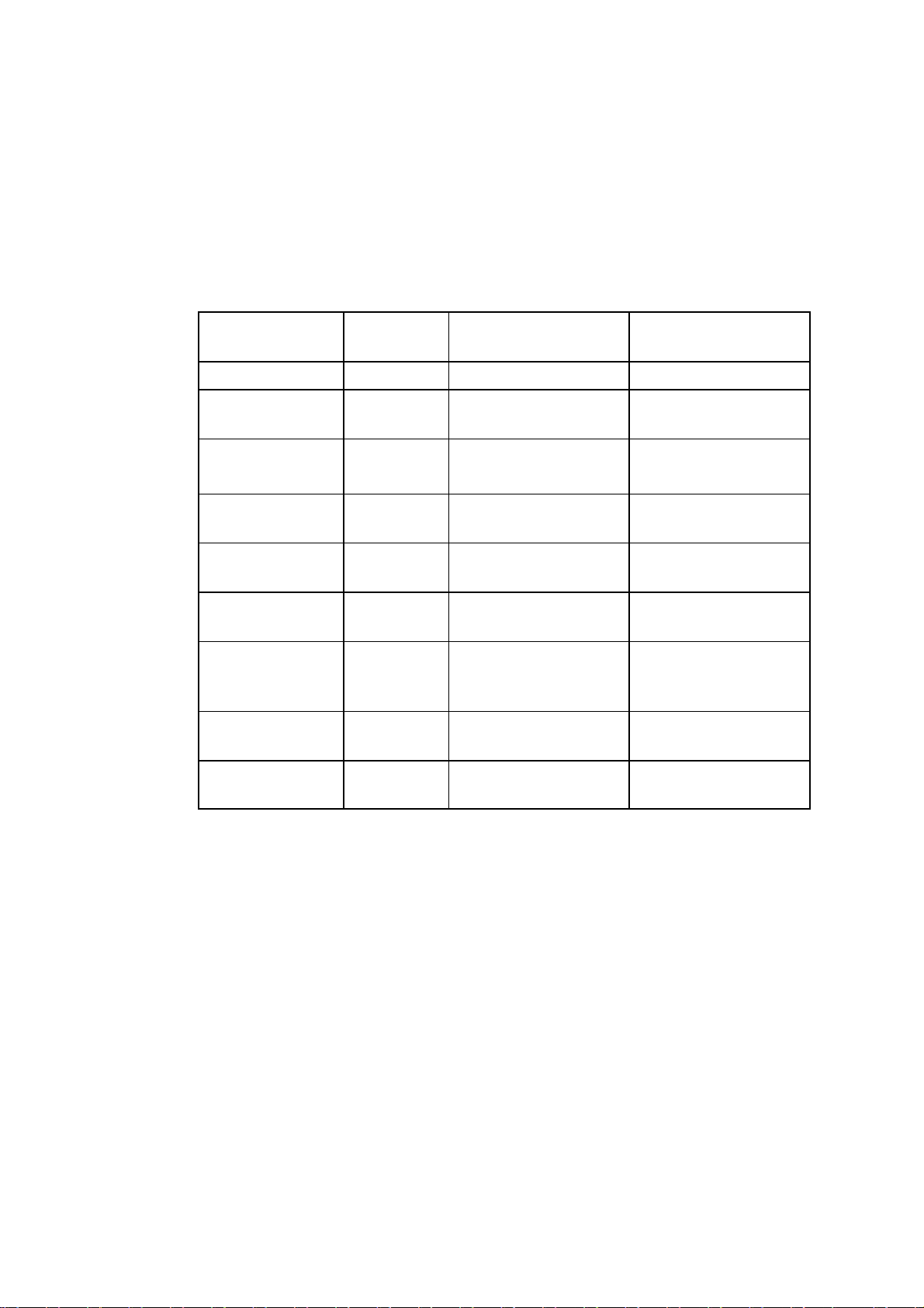
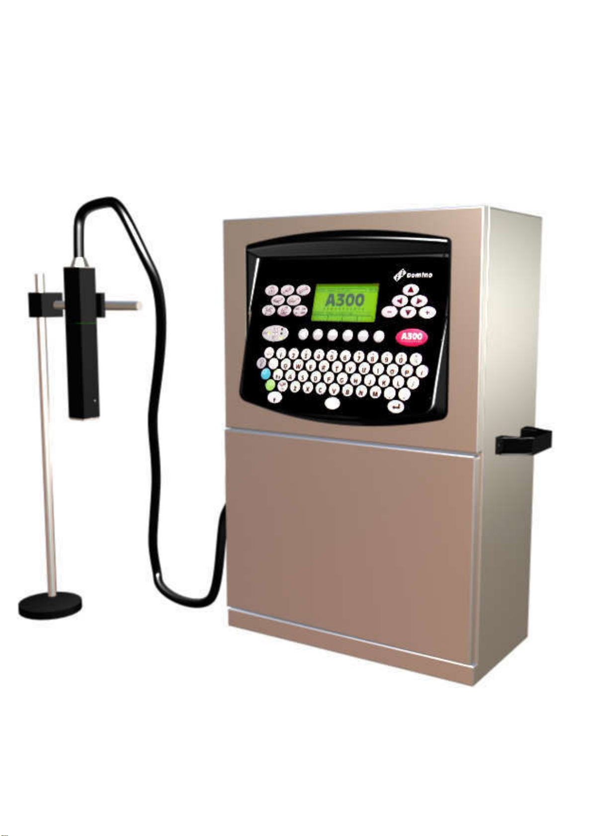
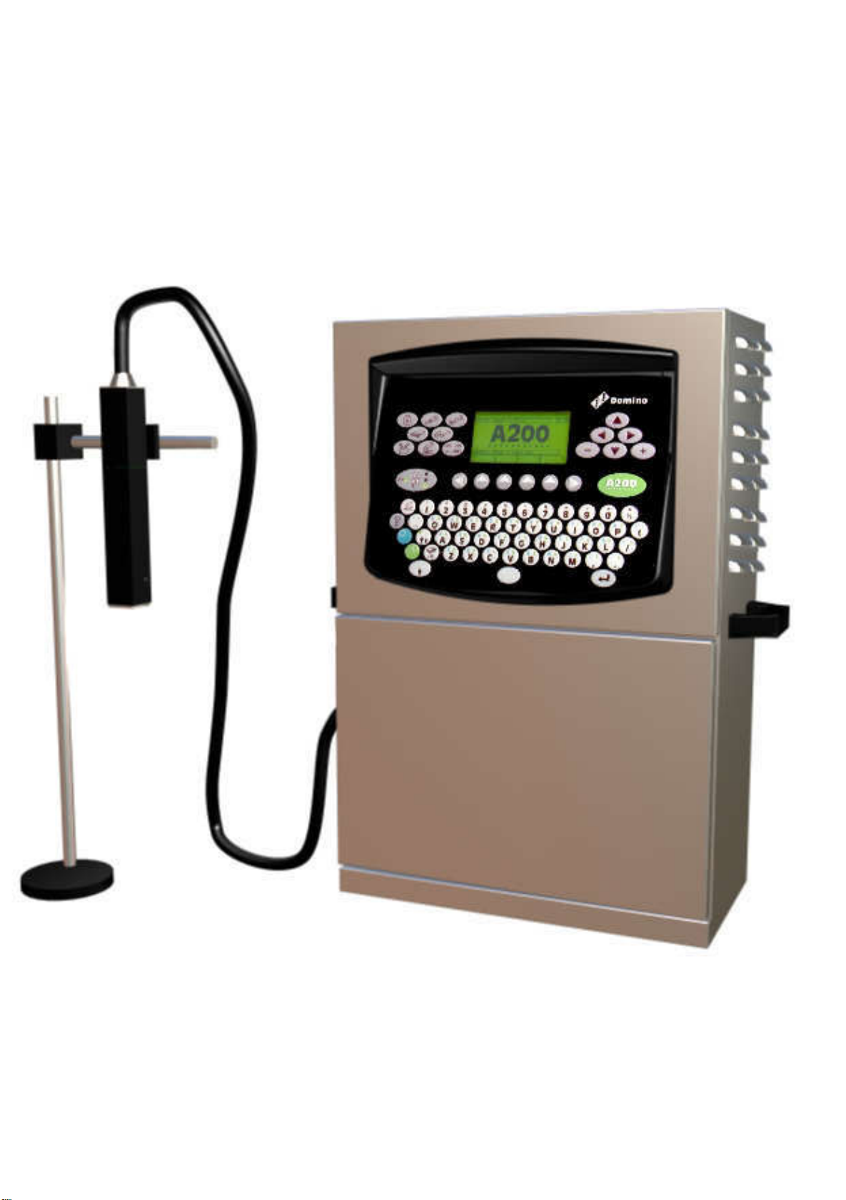
Domino A300 and Pinpoint, A200 & A100 Printers
to which this declaration relates, are in conformity with the following
standards:
EN50081--2 1992 Class B : Electromagnetic Compatibility
(Conducted),
EN50082--2 1992 : Electromagnetic Compatibility, General
Immunity Standard
EN55022--1 1987 Class A : Electromagnetic Compatibility
(Radiated)
EN60204 Part 1 : Safety of Machinery -- Electrical Equipment of
Industrial Machines
EN60950 : Safety of Information Technology Equipment, including
Electrical Business Machines
following the provisions of:
73/23/EEC : Low Voltage Directive
89/336/EEC : EMC Directive.
Bar Hill,
Cambridge,
17th July 1998 D.W. Reed
(2) 27080 Issue 1 Sept 98
Page 3

DOMINO A--SERIES
INK JET PRINTER
OPERATION AND MAINTENANCE MANUAL
This manual, Domino Part No. 27080, is for use in the maintenance of
Domino A300 and Pinpoint, A200 and A100 printers.
For instructions on how to operate the printer, refer to the Domino
A--Series Operator’s Pocketbook, Domino Part No. 27090.
Users of this ink jet printer are warned that is is essential to read,
understandandactaccordingtotheinformationgiveninPart1:Health
andSafety. Thispartofthemanualalsospecifiesasetofsymbolswhich
are used elsewhere in the manual to convey special warnings or
requirements. It is,therefore,essentialthat users arealso familiarwith
these symbols and act accordingly.
All rights reserved. No part of this publication may be reproduced,
stored on a retrieval system, or transmitted in any form, or by any
means, electronic, mechanical, photocopying, recording or otherwise,
without the prior permission of Domino UK Ltd.
Domino UK Ltd has a policy of continuous product improvement,the
Company therefore reserves the right to modify the specification
contained in this manual without notice.
E Domino UK Ltd 1998
For sales, service and inks please contact:
Domino UK Ltd Domino Amjet Inc
Bar Hill 1290 Lakeside Drive
Cambridge CB3 8TU Gurnee IL.60031
England U.S.A.
Tel: 01954 782551 Tel: 847 244 2501
Fax: 01954 782874 Fax: 847 244 1421
27080 Issue 1 Sept 98 (3)
Page 4

FCC Notice
Thisequipmenthasbeentestedandfoundtocomplywiththelimitsfor
a Class A digital device, pursuant to Part 15 of the FCC Rules. These
limits are designed to provide reasonable protection against harmful
interference when the equipment is operated in a commercial
environment.
Thisequipmentgenerates,usesandcanradiateradiofrequencyenergy
and, if not installed and used in accordance with the instruction
manual, may cause harmful interference to radio communication.
Operation of this equipment in a residential area is likely to cause
harmfulinterference,in whichcase,the userwillbe requiredtocorrect
the interference at his own expense.
Ifthis equipmentdoes causeharmful interferencetoradioortelevision
reception, which can be determined by turning the equipment off and
on, the user is encouraged to try to correct the interference by one or
more of the following measures:
D Re--orientate or relocate the receiving antenna
D Increase the separation between the equipment and receiver
D Connect the equipment into an outlet on a circuit different from
that to which the receiver is connected
D Consultthedealeroranexperiencedradio/TVtechnicianforhelp.
Any changes or modifications not expressly approved by the
manufacturercouldvoidtheuser’sauthoritytooperatetheequipment.
(4) 27080 Issue 1 Sept 98
Page 5

DOMINO A--SERIES
INK JET PRINTER
OPERATION AND MAINTENANCE MANUAL
CONTENTS
CHAPTER 1 Part 1 Health and Safety
Basic requirements and symbol
explanations.
Part 2 Introduction
Including printer specification, menu map
and use of the front panel.
CHAPTER 2 Part 3 Operation
Start up, shut down, cartridge and
reservoir replacement and how to create a
message.
Part 4 Display Messages and Fault Finding
Message interpretation and basic
fault--finding.
Part 5 Reference
Glossary of terms and screen descriptions
with details of the options.
CHAPTER 3 Part 6 Printer Description
Print head, cabinet, electronics and ink
systems.
Part 7 Maintenance
General and periodic maintenance, jet
alignment and ink changes.
Part 8 Repair
Print head, electronics system and ink
system.
Part 9 Spares and Accessories
Accessories, consumables, tools and
spares.
Part 10 Options
Additional parts for the printer.
Appendix A Installation
Installation and preparation for use.
Index To locate a subject in the manual.
Appendix B Compressor Driven Airdryer
Instructions and maintenance.
Appendix B Air Driven Airdryer
Instructions and maintenance.
27080 Issue 1 Sept 98 (5)
Page 6

(6) 27080 Issue 1 Sept 98
Page 7

DOMINO A--SERIES
INK JET PRINTER
OPERATION AND MAINTENANCE MANUAL
AMENDMENT RECORD
Amendment Date
All Parts at Issue 1 September 98
Appendix B : Compressor Driven Airdryer April 98
Appendix B : Air Driven Airdryer April 98
27080 Issue 1 Sept 98 (7)
Page 8

(8) 27080 Issue 1 Sept 98
Page 9
DOMINO A--SERIES
INK JET PRINTER
OPERATION AND MAINTENANCE MANUAL
In order that the machine continues to comply with the standards
required by the certification, the following components must not be
altered in any way or replaced by other types.
COMPONENT DOMINO
PART NO.
HV PSU 12170 Advance HI Volt GM7--19
PSU Assy 37758 Bulgin Power
Filter
Mains/Power
Switch
Mains/Power
Plug 3 Way
Mains/Power
Socket 7 Way
Mains/Power
PCB Assy
External
Interface
Fuse 20x5 (T)
1A
Fuse 20x5 (T)
4A
13492 Shaffner
37744 EAO 61--8420.12
13496 Bulgin PX0730/P
13498 Bulgin PX0744/S
25109 Domino 25109
01210 Little Fuse 213.001.MA000
01229 Little Fuse 218.004.MA000
MANUFACTURER MANUFACTURER
PART NO.
SAX110--34
Source
FN332--3/05
Bulgin
PS02/A0320/63
27080 Issue 1 Sept 98 (9)
Page 10

(10) 27080 Issue 1 Sept 98
Page 11

PART 1 : HEALTH AND S AFETY
CONTENTS
INTRODUCTION Page 1--3. . . . . . . . . . . . . . . . . . . . . . . . . . . . . . . . . . . .
Basic Requirements 1--3. . . . . . . . . . . . . . . . . . . . . . . . . . . . . . . . . . . . .
Storage 1--4. . . . . . . . . . . . . . . . . . . . . . . . . . . . . . . . . . . . . . . . . . . . . . . .
Fire Risk 1--4. . . . . . . . . . . . . . . . . . . . . . . . . . . . . . . . . . . . . . . . . . . . . .
Spillages and Disposal 1--6. . . . . . . . . . . . . . . . . . . . . . . . . . . . . . . . . .
SYMBOLS 1--7. . . . . . . . . . . . . . . . . . . . . . . . . . . . . . . . . . . . . . . . . . . . . . . .
27080 Issue 1 August 98 1--1
Page 12

HEALTH AND SAFETY
1--2 27080 Issue 1 August 98
Page 13

HEALTH AND SAFETY
HEALTH AND SAFETY
INTRODUCTION
Domino supplies Safety Data Sheets (SDS’s)giving specific safety
information with each of its ink, make--up and wash fluids. There are
also warnings on each container. The following notes are for general
guidance only.
Basic Requ irements
When used correctly, printing inks do not cause problems. However,
everybody using them should be familiar with the appropriate safety
standards and be aware of the precautions that should be taken. The
following are basic requirements.
D Proper standards of industrial practice relating to cleanliness and
tidiness must be maintained
D Inks and their containers must be stored and handled with care
D All who come into contact with inks must be properly instructed
in their use.
Directions for safe working practices vary according to the
environment. The following are broad principles so that necessary
precautions may be taken.
D Contact with the mouth must be avoided. Therefore eating,
drinkingorsmoking, or any personal habits oractionswhichmay
transfer ink to the mouth, must be avoided
D Contact with the eyes must be avoided. Suitable eye protection
must always be worn whenever there is any risk of splashing or
misting. If ink does get into theeyes,firstaid treatment is toflood
theaffectedeyefor15minuteswithsalinesolution,(orcleanwater
ifsalinesolutionisnotavailable),takingcarenottoallowthewater
to run into an unaffected eye. Medical aid must be obtained
immediately
D Most inks contain solvents which may injure the skin. Warning of
this is given on the SDSs. Barrier creams should be used and
protective clothing worn
27080 Issue 1 August 98 1--3
Page 14

HEALTH AND SAFETY
D Many inks contain materials which vaporise easily and can be
inhaled. Good ventilation is necessary
D Any usedcleaning materials,e.g.rags, paperwipes,are apotential
fire hazard. They must be collected for safe disposal after use
D After exposure to ink, all possible traces must be washed off as
soon as possible at the nearest washing facility.
Certain inks are allowed for use where they can be in indirect contact
with food. In these cases, the following precautions must be observed
in addition to those appropriate to hygiene:
D The inks must only be used in printers supplied from new for use
with these inks. Any repairsand replacementsmust use genuine,
new and unused spare parts
D The inks must not be used in printers which have previously been
used, at any time, for any other purpose.
In other words, a printer using ”food grade” ink can be converted for
use with other inks, but a printer which has used other inks must not
be converted for use with food grade ink.
Storage
Printing inks must be stored in well--ventilated buildings, or in areas
set aside for the purpose, chosen for safety in case of fire. Materials
based on volatile, flammable solvents must be stored in accordance
with local regulations.
Fire Risk
For an electrical fire, do not use water. If water must be used, such as
inthe caseof aNitro--cellulose inkfire (seebelow) thepowerMUST BE
REMOVED first.
Manyinks usedin inkjetprintingcontainNitro--celluloseas thebinder
and remain highly flammable when dry. Observe all warnings given
on the machine and the following safety instructions:
D If there has been an accumulation of dried ink, do not use ferrous
metal (iron or steel) scrapers to remove it, as they can produce
sparks
1--4 27080 Issue 1 August 98
Page 15

HEALTH AND SAFETY
D If dry Nitro--cellulose based ink ignites, it will generate its own
oxygenand canonly beextinguished bylowering thetemperature
with water
D If a Nitro--cellulose fire occurs, ENSURE THAT THE
ELECTRICAL POWER IS IMMEDIATELY REMOVED FROM
THE PRINTER BEFORE water is used to extinguish the fire.
Fire risk is a most important consideration where printing inks are
storedandused. Thedegreeoffirehazardwillvaryconsiderablyfrom
one type of ink or wash to another.
Water--based inkswillnot burn, althoughinksbased on water--alcohol
mixtures may burn if there is sufficient alcohol present. Prolonged
exposureof water--based systemstohigh temperatures mayevaporate
the water to give a flammable residue.
Solvent--based inks offer a greater degree of hazard depending on the
particular solvent or solvent combination. When there is a particular
hazard the appropriate information is given on the SDS.
Ink jet printers place small electrostatic charges on the ink drops used
for printing. In most circumstances, such as when they arrive at the
print surface, these electrostatic charges are either conducted away or
cannotaccumulate. However,duringmaintenance,printdropsmaybe
collected in a container, such as a beaker. It is essential that this
container is made of conducting material and is securely connected to
ground/earth. The electrostatic chargeswill then be safely conducted
to ground/earth.
If there is a fire, there is a likelihood that dangerous fumes will arise
from printing inks. For this reason ink must be stored where it can be
reached quickly by the fire fighting service, and where it will not
spread beyond the store.
27080 Issue 1 August 98 1--5
Page 16

HEALTH AND SAFETY
Spillages and Disposal
WARNING: Some dried inks are highly flammable. Clean up
allink spillagesimmediately. Do notallow theink
to dry or allow any build--up of dried ink spills.
Spillages must be cleaned up as soon as possible with the appropriate
solventmaterials andwith regardtothesafetyofpersonnel. Caremust
be taken to prevent spillages or residue from cleaning up entering
drains or sewage systems.
Inks and associated fluids are materials which conduct electricity.
Therefore, power to the printer must be switched off while spillages
inside the printer cabinet are being cleaned up.
Printing inks and associated fluids must not be treated as ordinary
waste. They must be disposed of using approved methods according
to local regulations.
1--6 27080 Issue 1 August 98
Page 17

HEALTH AND SAFETY
SYMBOLS
The following symbols are used in this manual. Where they appear
next to a procedure or instruction, they have the significance and
importance of written warnings and cautions.
Eye protection must be worn.
Protective clothing must be worn.
The equipment must be switched off and power removed.
Only trained personnel should carry out this procedure.
Beware of Electrostatic Discharge (ESD). Electrostatic precautions
must be used.
D Switch off machine first
D Wear a wristband connected to ground
D Avoid wearing clothing which can build up electrostatic voltages
D Use ESD protective bags to transport PCBs
D Only place PCBs on a mat made from a material which will
dissipate electrostatic voltages and which is connected to ground.
27080 Issue 1 August 98 1--7
Page 18

HEALTH AND SAFETY
1--8 27080 Issue 1 August 98
Page 19

PART 2 : INTRODUCTION
CONTENTS
GENERAL Page 2--5. . . . . . . . . . . . . . . . . . . . . . . . . . . . . . . . . . . . . . . . . .
PRINTER SPECIFICATION 2--6. . . . . . . . . . . . . . . . . . . . . . . . . . . . . . . .
Print Head 2--6. . . . . . . . . . . . . . . . . . . . . . . . . . . . . . . . . . . . . . . . . . . .
Cabinet 2--6.. . . . . . . . . . . . . . . . . . . . . . . . . . . . . . . . . . . . . . . . . . . . . .
Data Input 2--6. . . . . . . . . . . . . . . . . . . . . . . . . . . . . . . . . . . . . . . . . . . . .
Ink System 2--7. . . . . . . . . . . . . . . . . . . . . . . . . . . . . . . . . . . . . . . . . . . .
Environment 2--7. . . . . . . . . . . . . . . . . . . . . . . . . . . . . . . . . . . . . . . . . . .
General 2--7.. . . . . . . . . . . . . . . . . . . . . . . . . . . . . . . . . . . . . . . . . . . . . .
PRINTER CONTROL 2--8. . . . . . . . . . . . . . . . . . . . . . . . . . . . . . . . . . . . . .
Front Control Panel 2--8. . . . . . . . . . . . . . . . . . . . . . . . . . . . . . . . . . . . .
Display 2--8. . . . . . . . . . . . . . . . . . . . . . . . . . . . . . . . . . . . . . . . . . . . . . .
On/Off Switching 2--9. . . . . . . . . . . . . . . . . . . . . . . . . . . . . . . . . . . . . .
Topic Keys 2--11. . . . . . . . . . . . . . . . . . . . . . . . . . . . . . . . . . . . . . . . . . .
General Purpose Keys 2--12. . . . . . . . . . . . . . . . . . . . . . . . . . . . . . . . .
Help Key 2--13. . . . . . . . . . . . . . . . . . . . . . . . . . . . . . . . . . . . . . . . . . . . .
Currency Key 2--13. . . . . . . . . . . . . . . . . . . . . . . . . . . . . . . . . . . . . . . . .
Password System 2--13. . . . . . . . . . . . . . . . . . . . . . . . . . . . . . . . . . . . . .
Unicode Character Entry 2--14. . . . . . . . . . . . . . . . . . . . . . . . . . . . . . .
Importing and Exporting Data 2--14. . . . . . . . . . . . . . . . . . . . . . . . . .
User Port 2--14. . . . . . . . . . . . . . . . . . . . . . . . . . . . . . . . . . . . . . . . . . . . .
FRONT PANEL TOPIC KEY MENUS 2--15. . . . . . . . . . . . . . . . . . . . . . .
27080 Issue 1 August 98 2--1
Page 20
Page 21
Page 22
Page 23

INTRODUCTION
INTRODUCTION
GENERAL
This manual provides:
D A basic introduction to the printer and how to use the front panel,
with procedures that demonstrate how to manage the printer
D Reference sections describing the functions and messages
presented through the front panel
D A full description of the ink and electronics systems
D Maintenance and repair procedures.
Theprinterconsistsofaprinthead connectedtoastainlesssteelcabinet
by way of a flexible conduit. The cabinet contains an ink system and a
controlling electronic system operated through a panel on the cabinet
upper door. The printers are shown on pages 2--2, 2--3 and 2--4, with
internal views of thecabinetupper(electronic) and lower (inksystem)
compartments shown on pages 6--7 and 6--8.
27080 Issue 1 August 98 2--5
Page 24
INTRODUCTION
PRINTER SPECIFICATION
Print Head
Standard Finish: Aluminium alloy, Tufram coated
Dimensions: Width: 40mm (1.575”)
Depth: 42.5mm (1.673”)
Height: 280.5mm (11.05”)
Weight: 1.0kg (2.2lbs)
Nozzle size:
Pinpoint only:
Spacing from print surface:
Pinpoint only:
Working height relative to
cabinet base:
Conduit Length: 3 or 6 metres (10ft and 20ft)
60 or 75 micron
40 micron
12mm (0.47”) nominal
4mm (+/-- 1mm)
3m conduit: +/--2m (8ft 2ins)
6m conduit: +/--3m (10ft) (A300/A200
only)
A300 Pinpoint and A100: 3m only
Cab inet
Standard Finish: Brushed 316 stainless steel (A300)
Brushed 304 stainless steel (A200 & A100)
IP Rating: A300 is IP65 (1977)
A200/A100 are IP53 (1977)
Dimensions (A300 &
A200):
Width: 475mm (18.7”) --not incl. handles
Depth: 245mm (9.65”) --not incl. front panel
Height: 715mm (28.15) --not incl. feet
Weight (A300 & A200)
(incl. fluids):
Dimensions (A100): Width: 450mm (17.7”) -- not incl. handles
Weight (A100) (incl. fluids): 33kg (72.6lbs)
Control Panel: Polyester, Membrane touch button
For cabinet and print head installation dimensions, see Installation
page A--13.
36kg (79lbs)
Depth: 245mm (9.46”)
Height: 650mm (25.6”)
Data Input (Optional)
Interface: Serial, RS232, RS485
Rate: 110 -- 38.4kBaud software configurable
2--6 27080 Issue 1 August 98
Page 25
INTRODUCTION
Ink System
Ink Capacity (Reservoir): 1.2 litres (0.32 US gall.) -- automatically
metered
Ink Capacity (Cartridge): 825ml (0.218 US gall.)
Make--up Capacity
(Reservoir):
Make--up Capacity
(Cartridge):
Ink Viscosity Control: Automatic Viscometer
Ink Bleed Control: Automatic Start--Up/Shut--Down
Working Pressure:
Pinpoint only:
600 ml (0.16 US gall.) nominal --
automatically metered
825ml (0.218 US gall.)
Automatic, 2900mBar (42 psi) nominal
Automatic, 4000mBar (60psi) nominal
Environment
Temperature Range
(working):
Temperature Range
(Storage):
Humidity: 10 -- 90% RH (non--condensing)
Electrical Supply: 90--132V/180--264V 50/60Hz single phase
+5° to +45°C (42°F to 112°F)
--20° to +60°C (--4°F to +140°F) (machine dry
storage, wet dependent upon fluids)
Auto ranging, 200VA, internal fuse rating 4A
General
Acoustic Noise Level: Not more than 70 dBA
Positive Air Pressure (print
head):
Product detector/Shaft
encoder connectors:
Shaft Encoder Input: Open collector or TTL encoder
Beacon Connector (option): Bulgin ”Buccaneer” 7 way socket
Alarms Connector (option): Bulgin ”Buccaneer” 9 way plug
User Port Connector (option): Bulgin ”Buccaneer” 25 way socket
Communications Port
connector (option):
Power connector: Bulgin ”Buccaneer” 3 way plug,
Internal or external supply. Max
external supply pressure to cabinet
1 bar. (A100 is internal only)
Bulgin ”Buccaneer” 6 way socket.
12V 100mA for photocell or
proximity detector
Bulgin ”Buccaneer” 9 way socket
cable supplied
27080 Issue 1 August 98 2--7
Page 26
INTRODUCTION
PRINTER CONTROL
The printer is switched on by pressing the black button--switch on the
side of the cabinet. This supplies power to the whole printer and after
a short period control of the printer is transfered to the front panel.
Control Panel
Theprinter iscontrolledexclusivelythroughthefrontpanel. Thereare
two types of keys:
D Permanent keys with fixed functions (these form the majority of
keys)
D Function keys with functions which can change under software
control.
The main areas of the front panel are identified in the diagram below.
Topic Keys
Jet
On/Off
Key
Character
Set Keys
A1006_1
Displa y
Display
Front Panel Keyboard Layout
Cursor Keys
Data Entry Keys
Increment
Keys
Function
Keys
The display presentation has the following basic structure.
Alertbar shows amessagewhen a printeralertis raised. Themessage
flashes until acknowledged bypressingany character key or thespace
key,after whichthe messageis displayedcontinuously. Whenthealert
condition is cleared,themessageis cleared. If two or more alerts exist
2--8 27080 Issue 1 August 98
Page 27

INTRODUCTION
Alert Bar
Status Bar
Working Area
Information Bar
Key Option Bar
Screen Number
Print Symbol
Scroll Arrow
simultaneously, the highest priority alert is displayed. An
unacknowledged alert is always at a higher priority than any other
acknowledged alert. Screen messages are detailed in Part 4.
Status bar shows status and other non--alert information.
Working area provides a general presentation area for the function in
use.
Informationbar usually showswhich levelis currentlyselected, but is
also used for general information.
Key option bar shows up to four key options at any one time,
presentingthemaslabelsforthefour functionkeysimmediatelybelow
the screen. The options are scrolled left and right in groupsof four by
the keys on each side of the function keys, which appear when thereis
morethanfourkeyoptions. Scrollingresultsinthekeylabelschanging,
with the functions of the keys also changing to correspond with the
labelling.
Screen n umber provides a numerical identity for each screen.
Scroll arrow shows that the screen detail extends off the display. The
up-- and down--cursor keys must be used to show the hidden detail.
Print symbol shows printing as each Print Go signal is received. At
very slow print rates the symbol will appear to flash, but typical print
rates will give the appearance of a continuous symbol.
Jet On/Off Switching
TheJetOn/Off switchispressed toswitchon the jetandpressedagain
to switch off the jet. It is necessary to press the switch for two seconds
as a precaution against accidental use. The switch also carries the
following indicators:
Power On Indicator shows when the power is switched on at the
switch on the side of the cabinet.
Red Alert Indicator shows the printer has a fault which prevents
printing. The indicatorflasheswhilethe alert is unacknowledged and
27080 Issue 1 August 98 2--9
Page 28

INTRODUCTION
Power On
Indicator
Jet On/Off
Key
Red Alert
Indicator
Amber Alert
Indicator
Green
Indicator
displays steadily when the alert is acknowledged. It is extinguished
when the fault is cleared.
Amber Alert Indicator shows the printer has a fault that requires
attention. Theindicatorflasheswhilethealertisunacknowledgedand
displays steadily when the alert is acknowledged. It is extinguished
when the fault is cleared.
Green Indicator flashes while the printer is starting up or shutting
down and displays steadily when the printer is printing or ready to
print. It is extinguished by a fault or when the jet is not running.
2--10 27080 Issue 1 August 98
Page 29
INTRODUCTION
Topic Keys
Thetopic keyseach opensets ofscreenoptions. These areshown inthe
diagram on pg. 2--8 and described in detail in Part 5 : Reference.
Message Editor Provides access to the message
creation utilities.
Message Store Provides access to the stored
Messages.
Print Setup Provides access to the utilities
controlling the message being
printed, e.g. message
orientation.
Machine Setup Provides access to adjustments
in setting up the printer.
Service Provides access to the printer for
the Service engineer.
Memory Card Provides access to the PCMCIA
utilities.
Message
Monitor
Shows the message currently
being printed.
Lock--out Switches on password
protection, where used.
27080 Issue 1 August 98 2--11
Page 30
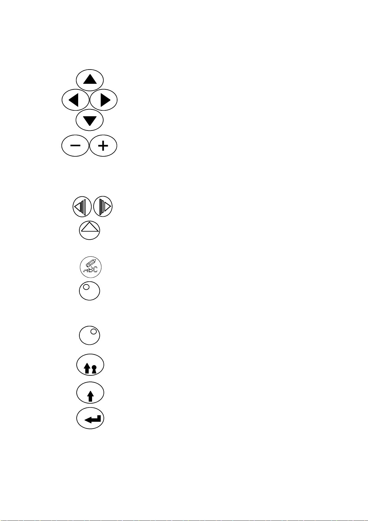
General Purpose Keys
Cursor Keys Four permanent keys used to
Increment Keys Two permanent keys used to
INTRODUCTION
move the cursor around the
screen.
increment and decrement values
shown on the screen and
marked with the highlight bar.
The effect of these keys on
settings and values is
immediate.
Option Key Bar
Scroll Keys
Two keys used to scroll the
functions in the keybar.
Function Keys Keys with functions identified
by the names in the keybar
immediately above.
Delete Key Deletes entries marked by the
highlight bar.
Alternative
Character Set -Left (Blue)
Press this key to select the top
left blue character on each
character key. Also (used with
the + and -- keys) controls screen
contrast.
Alternative
Character Set -Right (Green)
Press this key to select the top
right green character on each
character key.
Shift Lock Key Changes characters to lower case
until pressed again to return to
upper case characters.
Shift Key Hold down to change characters
to lower case.
Enter Key Press this key to put data into
the system to complete an
action.
2--12 27080 Issue 1 August 98
Page 31

INTRODUCTION
Help Key
Help Key Provides access to help
information concerned with the
current menu screen.
Currency Key
Currency Key Provides entry for localised
currency characters. Pressing
this key generates the minor
currency symbol (e.g. p,c) and
pressing it in combination with
the Shift key generates the major
currency symbol (e.g. £, $, etc).
Lockou t
Pressing the Lockout key prevents unauthorised changes through the
front panel or, for example, interference with the printer while it is
unattended. WithLockout selected, control of the printer is restricted
toswitchingon,switchingoffandinspectingthecurrentmessagebeing
printed (by pressing the Label Monitor key). Access to all other
functions requires the use of the appropriate password, provided this
has been set.
The Lockout screen also shows the internal clock, which is replaced in
all other cases by a screen number.
Password System
Entry to the Lockout and Message Monitor areas of printer control is
unrestricted, but all other areas can, if required, be protected by
password.Therearetwolevelsofpasswordprotection:Supervisor,and
Service. Each of these has a progressivelyhigher level of access to the
machine. When accessing a protected area, it is necessary to enter the
appropriatepassword (orthepassword forahigher level). Entry toall
areas with the same or lower protection status will subsequently be
unhindered. Returning to Lockout resets the password access. It is
possible to change the Supervisor password.
27080 Issue 1 August 98 2--13
Page 32

INTRODUCTION
Thefollowingtableshowstheavailablepasswordprotection:
LEVEL PASSWORDREQUIRED
Lockout None
MessageMonitor None
MessageEditor Supervisor
MessageStore Supervisor
PrintSetup Supervisor
MemoryCard Supervisor
MachineSetup Supervisor
Service Service
UnicodeCharacterEntry
Charactersthatarenotrepresentedbyakeycanbeavailablefor
printing.TheycanbeenteredintotheMessageEditororadataentry
dialogusingtheirUnicodeidentity.Thisisdonebyholdingdownboth
alternativecharactersetkeysandtypingtheUnicode4--digit
hexadecimalnumber(0000toFFFF).
ImportingandExportingData
MemoryCard
Thememorycardisablank,formattedPCMCIAcardwhichcanbe
usedtocopyandback--upmessagesandlogos.Thiscanthenbeused
asaback--upforthemessagesandlogos,orusedtocopymessagesand
logostoanotherprinter.
Itispossibletocopytheentiremessage(seepg.5--30)orlogostoreor
individualmessagesorlogos(seepg.5--23and5--25).
Back--up/RestoreCard
TheBack--up/RestorecardisadedicatedPCMCIAcardusedto
back--upandrestorealloftheconfigurationdataofaprinter.Itcanalso
beusedtorestorepartialconfigurationdatatothesameprinterorcopy
ittoanotherprinter(althoughtheprintersmustbethesame,i.e.
machinetype,inktype,etc.andhavethesameversionofmain
program).Thepartialrestorewillcopydatasuchas:nozzlesize,ink
type,conduitlength,etc.butnotdatasuchas:pumpspeed,modulation
voltage,etc.(seepg.5--44).
UserPort
ExternalcontroloftheprinterispossiblethroughtheUserPort.
2--14 27080Issue1August98
Page 33

27080 Issue 1 August 98 2--15
MESSAGEEDITOR
Print
Message
(pg.5--8)
Font
Size
(pg.5--8) (pg.5--9) (pg.5--9)
Insert
Clock
Serial
Number
Edit
(pg.5--11)
New
Message
(pg.5--11) (pg.5--11)
Bold
On/Off
Dblspace
On/Off
(pg.5--12) (pg.5--12)(pg.5--12)
Shift
Code
Insert
Logo
Text
Field
(pg.5--13)
Clock
Offsets
(pg.5--13)
MessageEditor(Cont.)
Start
MRC
(pg5--14)
End
MRC
(pg5--14)
MRC
Text
(pg5--15) (pg5--16)
Toggle
MRCs
Special
Setup
(pg.5--16)
INTRODUCTION
SPECIALSETUP
Exit
Message
Bold
(pg.5--16) (pg.5--17)
Reverse
Control
Inverse
Control
(pg.5--18) (pg.5--19)
Repeat
Printing
Message
Offset
(pg.5--19)
Product
Select#
(pg.5--20)
Raster
(pg.5--20)
MESSAGESTORE
Select
Message
(pg.5--21)
Print
Message
(pg.5--21)
StopMsg
Printing
(pg.5--21)
Save
Message
(pg.5--22)
Delete
Message
(pg.5--22)
Storage
Stats
(pg.5--23)
Export
Message
(pg.5--23)
Import
p:\)
(pg.5--23)
Import
r:\)
(pg.5--24
Logo
Store
(pg.5--24)
StopAll
Printing
(pg.5--25)
A300/A200
Only
LOGOSTORE
Cancel
FrontPanelTopicKeyMenus
OK Delete
Logo
(pg.5--24)
Storage
Stats
(pg.5--25) (pg.5--25)
Export
Logo
Import
(p:\)
(pg.5--25)
Import
(r:\)
(pg.5--25)
Page 34

2--16 27080 Issue 1 August 98
PRINTSETUP
Message
Bold
(pg.5--26) (pg.5--26)
Reverse
Control
MACHINESETUP
Master
Clock
(pg.5--31)
Serial
Port
(pg.5--31)
(pg.5--32)
SERVICE
Print
Head
(pg.5--37)
Ink
System
(pg.5--38)
MEMORYCARD
Export
Messages
(Pg.5--30)
Import
Messages
(pg.5--30)
Inverse
Control
(pg.5--26) (pg.5--26)
Ink
Data
Product
Counter
(pg.5--32) (pg.5--32) (pg.5--33)
Repeat
Printing
ViscosityExternal
I/F
(pg.5--39)
(pg.5--41) (pg.5--42) (pg.5--43)
SERVICE:EXTERNALI/F
Export
Logos
(pg.5--30)(pg.5--30)
Import
Logos
Enable
Printing
(Pg.5--27)
Day
Names
Month
Names
Config
Cancel OK
FrontPanelTopicKeyMenus
Print
Delay
(pg.5--27) (pg.5--28)
Reset
Serial#
Alpha
Hours
(pg.5--33)
Event
Log
Product
Sequence
Format
(pg.5--33)
Change
Resvr
(pg.5--43) (pg.5--44)
Start
Product
(Pg.5--44)
PRODUCTSEQUENCESIMULATION
Exit
Time
Change
Height
(pg.5--28) (pg.5--29)
Password
Setup
(pg.5--34) (pg.5--35) (pg.5--35)
Change
Width
Set
Currency
Backup
Printer
End
Product
Start
Sequence
Print
Once
Start
Cont
(pg.5--44)
Beeper
INTRODUCTION
Stop
Page 35

PART 3 : OPERATION
Repl. Resv
Repl. Cart.
Create Msg.
CONTENTS
START--UP Page 3--3. . . . . . . . . . . . . . . . . . . . . . . . . . . . . . . . . . . . . . . . . .
SHUT DOWN 3--3. . . . . . . . . . . . . . . . . . . . . . . . . . . . . . . . . . . . . . . . . . . .
INK RESERVOIR REPLACEMENT 3--4. . . . . . . . . . . . . . . . . . . . . . . . . .
INK AND MAKE--UP CARTRIDGE REPLACEMENT 3--6. . . . . . . . .
CREATING A MESSAGE 3--7. . . . . . . . . . . . . . . . . . . . . . . . . . . . . . . . . .
Display Contrast 3--7. . . . . . . . . . . . . . . . . . . . . . . . . . . . . . . . . . . . . . .
General Information 3--7. . . . . . . . . . . . . . . . . . . . . . . . . . . . . . . . . . . .
Creating the Message 3--8. . . . . . . . . . . . . . . . . . . . . . . . . . . . . . . . . . .
To Print the Message 3--8. . . . . . . . . . . . . . . . . . . . . . . . . . . . . . . . . . . .
To Save the Message 3--8. . . . . . . . . . . . . . . . . . . . . . . . . . . . . . . . . . . .
To Delete the Message from Store 3--8. . . . . . . . . . . . . . . . . . . . . . . . .
To Select an Existing Message 3--9. . . . . . . . . . . . . . . . . . . . . . . . . . . .
To Enter a Clock Entry 3--9. . . . . . . . . . . . . . . . . . . . . . . . . . . . . . . . . .
To Enter a Serial Number 3--11. . . . . . . . . . . . . . . . . . . . . . . . . . . . . . .
To Enter a Shift Code 3--12. . . . . . . . . . . . . . . . . . . . . . . . . . . . . . . . . .
To Enter a Text Field 3--12. . . . . . . . . . . . . . . . . . . . . . . . . . . . . . . . . . .
To Create a Machine Readable Code 3--13. . . . . . . . . . . . . . . . . . . . .
27080 Issue 1 August 98 3--1
Page 36

OPERATION
3--2 27080 Issue 1 August 98
Page 37

OPERATION
OPERATION
START--UP
Pressthepush--buttonswitchontheleftsideofthecabinet.
(Thefollowingswitch--onandautomaticrun--uptakesabout40
seconds).
DScreendisplays”Pleasewait...”
DGreenindicatorontheJetOn/Offkeybeginstoflash.
DStatusbarshowsmessagePrinterInitialising.Seepgs.2--8and2--9
forscreenandkeydetails.
Note: TheamberalertindicatorontheJetOn/Offkeymayflashanda
messageappearinthealertbaronthedisplay.
DStatusbarmessagechangestoPrinterOffandthegreenindicator
stopsflashingandremainsoff.
DEitherA300,A200,A100(dependingonprintertype)orDomino
Logoisdisplayedonthescreen.
Theprinterisnowreadyforthejettobeswitchedon.
PresstheJetOn/Offkeyfor2--3secondsoruntilanaudible“beep”is
heard(ifactivated--seepg.5--35).
(Turningonthejetisanautomaticproceduretakingabout70seconds).
DStatusbarshowsthemessageSequencingOn,
DGreenindicatorontheJetOn/Offkeybeginstoflash.
DStatusbarmessagechangestoReadytoPrint,greenindicatorshows
steadily.
Theprinterisnowreadytoprintmessages.
SHUTDOWN
CAUTION Donotremovepowertotheprinteruntil’PrinterOff’
isdisplayed.
PresstheJetOn/Offkeyfor2--3secondsoruntilanaudible“beep”is
heard(ifactivated--seepg.5--35).
(Shutdownisanautomaticproceduretakingabout3minutes).
DStatusbarshowsthemessageSequencingOff.
DGreenindicatorontheJetOn/Offkeybeginstoflash.
DStatusbarmessagechangestoPrinterOffandthegreenindicator
stopsflashingandremainsoff.
Pressthepush--buttonswitchontheleftsideofthecabinettoswitchoff
theprinter.
27080Issue1August98 3--3
Page 38

OPERATION
Reservoir Replacement
INK RESERVOIR REPLACEMENT
Themessages Inkchange neededin lessthan24 hoursand,later,Inkchange
needed in less than 2 hours will appear near the end of the reservoir life
(If a long--life system is being used, these warnings will appear at 300
hours and 24 hours before the end of reservoir life). Printing will not
continue beyond the expiry of the reservoir life.
It is necessary to enter the reservoir quality code of the new reservoir
and reset the reservoir replacement alarms, using the following
procedure:
(1) Press the Service key and enter the password if required.
(2) Use the key bar scroll keys to find the Change Resvr option at the
bottom of the screen.
Change
Resvr
OK
(3) Pressthefunction key markedbyChange Resvr andthe screenwill
change to show a prompt requesting input of the Quality Code
printed on the label of the new ink reservoir.
(4) Type in the reservoir quality code.
(5) Press the function key marked OK.
If the correct code is typed in, the reservoir run time will be reset and
the alarms cancelled. Proceed to step (6).
If the number is typed inaccurately, it can be corrected by typing in
again. If an invalid code number is typed, the number will not be
accepted and messages in the information bar will indicate the
problem, e.g. Incorrect ink type, Ink out of date, or Resvr already used (an
old reservoir number). The offending reservoir should be replaced.
(6) Shut down the printer using the proper procedure.
(7) Switch off the printer.
Replace the reservoir as follows.
Notes (1) Tissue will be required for this procedure.
Removetheink cartridge (seediagramon thenextpage). Unscrewthe
manifold locking ring, lift the manifold out of thereservoirand secure
themanifoldintothemanifoldretainerinsidethetopofthe inkcabinet.
Fitacaptothereservoir. Pushthemetalreservoirretainingbarandpull
the reservoir forward to remove.
To fit a new reservoir, reverse the above procedure.
3--4 27080 Issue 1 August 98
(2) The make--up reservoir is non--replaceable.
Page 39

OPERATION
Manifold
Retainer
Reservoir
Retaining Bar
MG188- -1
MG187- -1
Removing the Ink Reservoir
Reservoir
Retaining Bar
MG189- -1
Refitting the Ink Reservoir
27080 Issue 1 August 98 3--5
Page 40

OPERATION
INK AND MAKE--UP CARTRIDGE
REPLACEMENT
Note: If only small amounts of ink are being used by the printer, it may
notbe necessaryto fitan inkcartridge. Leavetheink manifoldseal
inplace andonly fitan inkcartridge whena requestappears onthe
display.
Messages‘AddInkCartridge’or‘AddMake--upCartridge’willappear
on the front panel display when the ink or make--up cartridges need
replacing, and the amber alert will illuminate.
Theinkcartridge is rotated anti--clockwiseandthemake--up is rotated
clockwise to free them before being lifted away. This mechanism
ensures that the cartridges cannot be fitted onto the wrong manifold.
To fit a cartridge, cut off the sealing tab and push on to the correct
manifold.
Rotate and lift
cartridges to
remove.
MG184- -1
Press cartridge down
firmly to fit.
MG186- -2
Cartridge Replacement
MG183- -1
If the make--up cartridge is not replaced, the make--up reservoir will
empty and the ink viscosity will eventually go outside limits. Also,
headflushingwillnotbecarriedoutwhentheprinterisshut downand
ink may be deposited on the print head components. Thus, although
the printer can still be used, head faults may occur.
3--6 27080 Issue 1 August 98
Page 41

OPERATION
Create Message
CREATING A MESSAGE
Thefollowingshowshowtocreateandprintamessage. Thesuggested
entries could be used as a working example. All of the screens
presented on the display are fully described in Part 5 : Reference.
Displa y Contrast
For comfort, the display contrast can be adjusted by pressing the blue
alternative character set key and adjusting the contrast using the
increment (+ and --) keys.
General Information
The following is general advice for using the keyboard. For example,
if a mistake is made, and it is required to delete a character, the cursor
keys (see pg. 2--12) can be used to move a highlight bar over the
character. Pressing the delete key (see pg. 2--12) will then remove the
character. Note that new characters are always inserted immediately
in front of the highlight. Therefore, if a replacement character is
required in the same place as a deleted character, type in the new
character without moving the highlight.
Font (character) size, bold characters and double spacing can be
selected as function key options. Pressing the key activates the option
and allsubsequententrieswill be size/bold/spaced accordingly,until
the key is pressed again.
Valuescanbetypedin,or changedbyusingtheincrementkeys (seepg.
2--12). Values changed with the increment keys are effective
immediately. By contrast, values typed in using the number keys
become effective only when OK or the equivalent is selected using the
function keys, or a +/-- key is pressed.
Font size is indicated by the vertical size of the cursor. If a larger font
size is inserted into a multi--line message, the other characters will be
automatically arranged around the larger characters.
Note: The following attributes/parameters can be set as special setups
into individual messages (through Message Editor) and also set
into the printer as overall global settings (through Print Setup):
Bold
Repeat messages
Reverse/Inverse
Individual message settings take priority over the global settings.
27080 Issue 1 August 98 3--7
Page 42

OPERATION
The key labels along the bottom of the screen may not show the
requiredoptions immediately. Ifnecessary, use the scrollkeys(seepg.
2--12) to move the options acrossthescreen. To select the option, press
the key below the label on the screen.
To Create the Message
(1) Press the Message Editor topic key.
(2) Type in the message (e.g. abc).
Creating a detailed message can include entering clock data, serial
numbers, shift codes or text fields (see below). To continue with a
simple message, proceed as follows.
To Print the Messa ge
(1) With Message Editor selected, press the scroll keys to search the
key options and find Print Message.
Print
Message
Save
Message
OK
(2) Press the key below Print Message the prompt ’Message Ready for
Printing’ is displayed. The message will now be printed at each
Print Go signal if the printer is in the Ready to Print state.
Note: Ifanon--linemessageischangedinanyway,itisnecessarytopress
Print Message again to implement the changes.
To Save the Message
(1) Press the Message Store key. (The screen will change and may
show the name of a previous message -- ignore this!)
(2) Select Save Message from the key options along the bottom of the
screen (by pressing the key under the label).
(3) Type in the name of the message (e.g. ”Example”).
(4) Select OK from the key options (by pressing the key under the
label).
To Delete the Message from Store
Delete
Message
(1) WithMessage Storeselected, pressthe scrollkeys tosearchthekey
options and select Delete Message. The screen will change to show
a list of names of stored messages.
(2) Use anup-- or down--cursorkeyto move thehighlightbar to cover
the name of the required message, e.g. ”Example”. The list of
3--8 27080 Issue 1 August 98
Page 43

OPERATION
message names may extend off the screen -- continuing to use the
cursor key will automatically scroll the list.
Note: Amessagebeing currentlyusedfor printing (marked ”>”)cannot
be deleted.
Delete
Message
OK
Cancel
Select
Message
OK
(3) Select Delete Message fromthekey options. Thescreenwill change
to show Delete message? and the message name.
(4) SelectOKtodeletethemessage andthescreenwill returntothelist
of messages.
The deleted message name will not now be included in the list and
steps (2) to (4) can be repeated to delete any other messages.
(5) Select Cancel from the key options.
To Select an Existing Message
(1) WithMessage Storeselected, pressthe scrollkeys tosearchthekey
options and select Select Message. The screen will change to show
a list of names of stored messages.
(2) Use down-- andup--cursor keys to move the highlightbartoselect
the name of the required message.
(3) Select OK from the key options. The display will change to show
the name of the chosen message only.
Note: To print this message, select Print Message from the key options.
Insert
Clock
(4) Press Message Editor and the display will show the full message.
To Enter a Clock Entry
(1) With Message Editor selected, select Insert Clock from the key
options. The display will change to show the Insert Clock screen
with a highlight bar over Clock Offset Number.
(2) Type in a numerical value, e.g. 2. (This value selects one of four
clocks on A300/A200, or one of two clocks on A100, containing
time offsets entered into the printer by way of the Clock Offsets
option. For example, a continuously updated date four weeks
ahead of the current date can be inserted into the message).
(3) Press the down--cursor key to move the highlight bar down over
Format.
The clock entries consist of names, etc. arranged in a range of formats.
Thenames,codes, available formats,etc. canallbe changedifrequired
(see pgs. 5--33 and 5--34).
27080 Issue 1 August 98 3--9
Page 44

OPERATION
(4) Useanincrementkeytochangethedateformatinthehighlightbar
to a suitable format.
(5) Select OK from the key options. The display will change to show
OK
the message with the clock detail inserted at the cursor position.
Clock entries on the display will not be updated. However, the
printed messages will have clock entries updated fromthemaster
clock and Message Monitor will also display the correct clock
information after each received print go.
3--10 27080 Issue 1 August 98
Page 45

OPERATION
To Enter a Serial Number
(1) With Message Editor selected, press the scroll keys to search the
Select
Message
key options and select Serial Number.
The screen will change to show the parameters controlling the serial
numbering. Theseincludethe startnumber (firstlimit),finish number
(secondlimit) andthe changebetweenmessages (stepsize). If thestart
number is below the finish number the change (step) will be
incremental, i.e. positive. If the start number is above the finish
number, the change (step) will automatically be decremental, i.e.
negative. Also,ifrequired,thesame serial number can be enteredinto
a selected number of messages before it is changed (Repeat Count).
More advanced serial numbers can be set up, to include a letter--type
prefix or suffix and batch linking between two serial numbers (batch
linking on A300/A200 only). In the case of alphanumeric serial
numbers,theorder (precedence)in which thealphaand numericparts
areupdatedcanbeselected.Inthefollowing steps,the exampleentries
willcreatea serialnumberAA0000, AA0001 . ..throughAX0000 . . up
to KK1000, increasing at each step by 1.
(2) Use down-- and up--cursor keys to move the highlight bar and
select the details of the serial number, and type in the required
values. For example:
First Limit: 0. . . . . . . . . . .
Second Limit: 1000. . . . . . . . .
Start Value: 0. . . . . . . . . .
Leading Zeros: Y es(selected with the increment keys). . . . . . . .
Step Size: 1. . . . . . . . . . . .
Repeat Count: 0. . . . . . . .
The serial number is displayed at the bottom of the screen.
(3) If a more complex serial number is required, select Advanced.
(4) Use down-- and up--cursor keys to move the highlight bar and
select the details of the serial number, and enter the required
values. For example:
Alpha: Prefix (selected with the increment keys). . . . . . . . . . . . . . .
Batch Link: No (selected with the increment keys). . . . . . . . . . .
(A300/A200 only)
Precedence: Numeric (selected with the increment keys). . . . . . . . . . .
First Limit: AA. . . . . . . . . . .
Second Limit: KK. . . . . . . . .
27080 Issue 1 August 98 3--11
Page 46

OPERATION
Lower Character: A. . . . . .
Upper Character: X. . . . . .
Start Value: AA. . . . . . . . . .
(5) Select OK from the key options.
OK
To Enter a Shift Code
(1) With Message Editor selected, press the scroll keys to search the
functionkey optionsand selectShift Code. The displaywillchange
Shift
Code
OK
Text
Field
to show the Shift Code screen. Up to 24 shift codes can be entered
inthe formof startand stoptimes (inhours andminutesaccording
to the 24 hour clock system) and a shift code name (in the String
column). Move the highlight bar using the up-- and down--cursor
keys to mark the entry being entered or amended.
(2) Type in a shift code, e.g. Start 08:30, Stop 12:30, String Red.
(3) Select OK from the key options. The display will change to show
the message and, provided the current real time falls within the
specified shift code start and stop times, the shift code name, e.g.
Red, will be inserted at the cursor position. (If the shift code time
isoutsidethetimelimits,theshiftcodepositioninthemessagewill
show as a blank space.)
To Enter a Text Field
A text field is a blank area which can be left within a message, e.g. to
avoid interference with other pre--printed information.
(1) With Message Editor selected, select Text Field from the key
options. The display will change to show the Text Field screen.
Enter a value representing the size of the field (measured in
characters).
(2) Select OK from the key options. The message will re--appear
OK
showing a space sized to the value entered in the previous step at
the position of the cursor.
3--12 27080 Issue 1 August 98
Page 47

OPERATION
To Create a Machine Readable Code (MRC) (A300/A200
only)
The following procedure is carried out in Message Editor, either as a
new message or as part of a message being constructed.
During the following procedures, decisions on the following will be
required:
(a) MRC type
(b) MRC data which is appropriate to the MRC type
(c) Positionofany human--readabletext relatedto theMRC. This
is usually indented into a barcode, but can, if required, be
placed elsewhere.
(d) Type of human readabletext. This is usually thesamedataas
the MRC and, ifsetupaccording to the followingprocedures,
amendmentsorupdatestotheMRCwillthenbeautomatically
Font
Size
Start
MRC
applied to the human--readable text.
During the procedures,key labels along the bottom of the screen may
not show the requiredoptions. It will be necessary to be familiar with
using the scroll keys (see pg. 2--12) to move the key options across the
screen and selecting an option by pressing the key below the label on
the screen.
It will also be necessary to be familiar with using the up-- and
down--cursorkeysto move thehighlightbarto select settings given on
a display screen.
(1) Inspectthecursoronthe displayand pressthe FontSizeoption key
until it is the size of the required MRC.
(2) SelectStartMRCoption keyandnotetheappearanceofthesymbol
”>” at the correct MRC size.
Height
(Lines)
Barcode
Size
(Lines)
123456
Quiet Zone
(Left)
27080 Issue 1 August 98 3--13
Indentation
Width
Quiet Zone
(Right)
Page 48

OPERATION
(3) Type in the MRC message.
End
MRC
OK
(4) Press End MRC option key. The screen will change to show the
MRC Identifier i.e. whether the barcode is the first, second, etc. in
the message, and the MRC type.
(5) If necessary, use the increment keys to change the MRC setting to
the required type.
To Create a Barcode:
(6) If asimplebarcode onlyisrequiredselectOK and the barcodewill
appear. If human--readable information is to be included, select
Advanced as in step (7).
To confirmthebarcode data, usetheToggle MRC’soption key to switch
between the barcode and its human--readable version. (Toggling the
data does not affect printing -- only the barcode is printed.) However,
selecting the human--readable version helps editing, as the cursor can
be moved to the required character and changed in the normal way.
Note the ”<” symbol at the end of the barcode data. Marking this and
selectingEdit returnsthescreentostep (4)allowing thebarcodedetails
tobechanged. Alternatively,togglingtothe barcodeandselectingEdit
also returns the screen in step (4).
Advanced
OK
OK
Font
Size
(7) The barcode data can be printed in human--readable form, either
before or after the barcode, or it can be indented into the barcode
as shown in the diagram. Some barcodes (such as EAN 13) use a
double indentation. Select Advanced.
(8) WithAdvanced selected,setthe indentation width. Foranexact fit,
this width ismeasuredin strokes, butfordemonstrationpurposes
enter any large number (e.g. 1000) to create the largest available
width in the barcode.
(9) Enter the height (in number of lines) of the barcode above the
indentation (see diagram).
(10)If required, values (in strokes) can be entered to give quiet zones
(clear spaces) at the beginning and end of the barcode.
(11) Select OK to return to the barcode screen.
(12)SelectOK to returnto the MessageEditorscreen. The barcodewill
now show the indentation(s).
(13)Inspectthe cursor atthefront ofthedisplay and pressthe Font Size
optionkey untilitisthesize oftherequiredbarcode. Ifthebarcode
3--14 27080 Issue 1 August 98
Page 49

OPERATION
text is to be fitted into the indentation, it is important that this is a
height suitable to fit into the indentation (or the text will be fitted
outside the barcode). Then use the cursor keys tomovethecursor
to the required position.
MRC
Text
OK
MRC
Text
(14)SelectMRC Text or, if thebarcodeuses two indentations,gotostep
(18).
(15)HighlighttheNumberofCharactersandenterthenumberofbarcode
characters.
(16)Select OK.
(17)The barcode will appear including the human--readable text. If
required, this text can be re--positioned by entering character
spaces or thin spaces (shift + space keys).
(18)In a barcode using two indentations, selected human--readable
characters would be placed in the two positions. Select MRC Text.
(19)Select Number of Characters and enter the number of characters to
beput intothefirst indent(thisis usuallyhalf ofthetotal number).
Leave the Offset value at zero.
First indent characters
OK
MRC
Text
OK
123456789123
Offset
Second indent characters
123456 789123
(20)SelectOK and checkthatthe requiredcharacters appearin thefirst
indentation. Ifnecessarymove thecursor tothestart ofthesecond
indentation.
(21)Select MRC Text again.
(22)SelectOffsetandenter the number of characters not required to be
shown. Select Number of Characters and enter the number of
characters (usually half of the total number), beyond the offset, to
be put into the second indent.
(23)SelectOK and checkthatthe requiredcharacters appearin thefirst
and second indentations.
27080 Issue 1 August 98 3--15
Page 50

OPERATION
To Create A Dot Code:
Followsteps under’CreateaMachineReadableBarcode’up tostep(5),
then continue as follows:
(6) Select therequiredcode(Snowflakeor Data Matrix) and press the
Advanced key.
(7) Select the requiredDot Code parameters in this screen. These are
as follows:
Formatwhichdescribesthetypeofdatatobeencoded,optionsare:
SNOWFLAKE DATA MATRIX
1. Numeric only (0..9) 1. Numeric only (0..9)
2. Upper case only (A..Z) 2. Alpha only (A..Z)
3. Lower case only (a..z) 3. Printable ASCII
4. Punctuation (;:’,.?!)
5. Alphanumeric (A..Z a..z 0..9)
Error CorrectionCode (ECC) applied to dotcode. Use the help(?)
to enter the required ECC for Snowflake, values of none and
checksum are not permitted and will be changed to the minimum
supported value of 10%. For Data Matrix, ECC values of 000, 010
and 040 are not supported and are changed to the minimum
supported value of 050. The reason that numbers are entered is to
make the menu generic for all dotcode symbologies (see the
following Help screens).
(8) Select the height and width required and press OK.
3--16 27080 Issue 1 August 98
Page 51

OPERATION
DENSITY
DENSITY
Snowflake Encryption Capacities
10% E rror Code Correction
DENSITY MAXIMUM CHARACTER ENCRYPTION CAPACITY
Numeric
Format 1
Upper
Case
Format
2
Lower
Case
Format
3
Punctuation
Format 4
Alphanumeric
Format 5
7 x 16 4 3 3 4 3
7 x 24 10 8 8 10 7
8 x 8 n/a n/a n/a n/a n/a
9 x 9 2 1 1 2 1
10 x 10 2 2 2 2 1
11 x 11 6 4 4 6 4
11 x 24 23 19 19 23 15
12 x 12 8 7 7 8 5
12 x 24 26 21 21 26 17
13 x 13 12 9 9 12 8
14 x 14 15 12 12 15 10
15 x 15 17 13 13 17 11
16 x 16 21 17 17 21 14
16 x 24 39 31 31 39 26
20% E rror Code Correction
DENSITY MAXIMUM CHARACTER ENCRYPTION CAPACITY
Numeric
Format 1
Upper
Case
Format
2
Lower
Case
Format
3
Punctuation
Format 4
Alphanumeric
Format 5
7 x 16 2 2 2 2 1
7 x 24 6 5 5 6 4
8 x 8 n/a n/a n/a n/a n/a
9 x 9 1 n/a n/a 1 n/a
10 x 10 2 1 1 2 1
11 x 11 3 2 2 3 2
11 x 24 15 12 12 15 10
12 x 12 4 3 3 4 2
12 x 24 16 13 13 16 11
13 x 13 6 5 5 6 4
27080 Issue 1 August 98 3--17
Page 52

OPERATION
DENSITY
14 x 14 8 7 7 8 5
15 x 15 11 9 9 11 7
16 x 16 13 10 10 13 9
16 x 24 25 20 20 25 17
40% E rror Code Correction
DENSITY MAXIMUM CHARACTER ENCRYPTION CAPACITY
Numeric
Format 1
Upper
Case
Format
2
Lower
Case
Format
3
Punctuation
Format 4
Alphanumeric
Format 5
7 x 16 n/a n/a n/a n/a n/a
7 x 24 2 2 2 2 1
8 x 8 n/a n/a n/a n/a n/a
9 x 9 n/a n/a n/a n/a n/a
10 x 10 n/a n/a n/a n/a n/a
11 x 11 1 n/a n/a 1 n/a
11 x 24 6 5 5 6 4
12 x 12 1 1 1 1 1
12 x 24 7 5 5 7 4
13 x 13 2 1 1 2 1
14 x 14 2 2 2 2 1
15 x 15 4 3 3 4 2
16 x 16 5 4 4 5 3
16 x 24 11 9 9 11 7
3--18 27080 Issue 1 August 98
Page 53

OPERATION
DataMatrixSquareEncryptionCapacities
ErrorCodeCorrection50
DENSITY MAXIMUMCHARACTERENCRYPTIONCAPACITYDENSITY
NumericFormat1 Alphanumeric
Format2
11x11 1 1 n/a
13x13 10 6 4
15x15 20 13 9
16x16 20 13 9
ASCIIFormat3
ErrorCodeCorrection80
DENSITY MAXIMUMCHARACTERENCRYPTIONCAPACITYDENSITY
NumericFormat1 Alphanumeric
Format2
13x13 4 3 2
15x15 13 9 6
16x16 13 9 6
ASCIIFormat3
ErrorCodeCorrection100
DENSITY MAXIMUMCHARACTERENCRYPTIONCAPACITYDENSITY
NumericFormat1 Alphanumeric
Format2
13x13 1 1 n/a
15x15 8 5 3
ASCIIFormat3
16x16 8 5 3
ErrorCodeCorrection200
DENSITY MAXIMUMCHARACTERENCRYPTIONCAPACITYDENSITY
NumericFormat1 Alphanumeric
Format2
8x18 10 6 6
8x32 20 13 8
10x10 6 3 3
12x12 10 6 5
12x26 32 22 14
12x36 44 31 20
14x14 16 10 6
16x16 24 16 10
16x36 64 46 30
16x48 98 72 47
ASCIIFormat3
27080Issue1Sept98 3-19
Page 54

PART 4 : DISPLAY MESSAGES AND FAULT
FINDING
CONTENTS
INTRODUCTION Page 4--3. . . . . . . . . . . . . . . . . . . . . . . . . . . . . . . . . . . .
Red alerts 4--3. . . . . . . . . . . . . . . . . . . . . . . . . . . . . . . . . . . . . . . . . . . . .
Amber alerts 4--3.. . . . . . . . . . . . . . . . . . . . . . . . . . . . . . . . . . . . . . . . . .
Fault Acknowledgement 4--4. . . . . . . . . . . . . . . . . . . . . . . . . . . . . . . .
ALERT BAR MESSAGES 4--4. . . . . . . . . . . . . . . . . . . . . . . . . . . . . . . . . . .
STATUS BAR MESSAGES 4--14. . . . . . . . . . . . . . . . . . . . . . . . . . . . . . . . .
INFORMATION BAR MESSAGES 4--16. . . . . . . . . . . . . . . . . . . . . . . . .
PRINTER FAULTS 4--17. . . . . . . . . . . . . . . . . . . . . . . . . . . . . . . . . . . . . . .
No Indicators Showing. 4--17. . . . . . . . . . . . . . . . . . . . . . . . . . . . . . . .
Machine Does Not Print. 4--17. . . . . . . . . . . . . . . . . . . . . . . . . . . . . . .
Print Position Incorrect. 4--17. . . . . . . . . . . . . . . . . . . . . . . . . . . . . . . .
Print Size Too Small. 4--18. . . . . . . . . . . . . . . . . . . . . . . . . . . . . . . . . . .
Gutter Over--flowing Ink. 4--18. . . . . . . . . . . . . . . . . . . . . . . . . . . . . . .
PRINT QUALITY FAULTS 4--19. . . . . . . . . . . . . . . . . . . . . . . . . . . . . . . .
27080 Issue 1 August 98 4--1
Page 55

DISPLAY MESSAGES AND FAULT FINDING
4--2 27080 Issue 1 August 98
Page 56

DISPLAYMESSAGESANDFAULTFINDING
DISPLAYMESSAGESANDFAULTFINDING
INTRODUCTION
Thereareseparatebarsonthedisplayshowing:
Dalertmessages(seebelow)
Dstatusmessages(seepg.4--14)
DInformationmessages(seepg.4--16).
RedAlerts
RedalertsareshownbyaflashingredLEDindicatoronthejeton/off
switchandamessageflashinginthealertbar(seepg.4--4).Theyshow
thepresenceoffaultsandstoptheprinterprintingorpreventanunsafe
conditionoccurring.Therearetwotypes:
Non--recoverableThejetwillshutoff(withoutfollowingthenormal
sequencing).Ifthefaultconditionisstillpresentwhenacknowledged
(seebelow),theredLEDwillremainonandthealertbarmessagewill
showcontinuously. Ifthefaultconditionhasclearedwhen
acknowledged,theredLEDwillextinguishandthemessagewillbe
removed.
RecoverableThegreenLEDonthejeton/offswitchwillflashasthe
printerattemptstorecover.Thejetremainsswitchedon.Ifrecovery
issuccessful,thegreenLEDwillremainonandtheredLEDwillflash
untilacknowledged. Whenacknowledged,theredLEDwill
extinguishandthealertbarmessagewillberemoved.
AmberAlerts
Amberalertsareusedtoinformtheoperatorthattheprinterisinneed
ofattentionorthattherearemessagehandlingerrors.
Ifthefaultconditionisstillpresentwhenacknowledged(seebelow),
theamberLEDwillremainonandthealertbarmessagewillshow
continuously.Ifthefaultconditionhascleared,theamberLEDand
alertbarmessagewillflashuntilacknowledged,whentheamberLED
willextinguishandthealertbarmessagewillberemoved.
27080Issue1August98 4--3
Page 57

DISPLAY MESSAGES AND FAULT FINDING
Fau lt Acknow ledgement
Alertbarmessagesflashuntilacknowledgedbypressinganycharacter
keyorthespacekey,afterwhichthemessageisdisplayedcontinuously.
Dependingon thealert, somemessages areclearedwhenthe condition
is cleared. In other cases the message is retained until acknowledged.
If two or more alerts exist simultaneously, the highest priority alert is
displayed. An unacknowledged alert is always at a higher priority
than any acknowledged alert.
All reports are recorded in the error log, together with times of
acknowledgement and repair.
ALERT BAR MESSAGE S
Alert Bar
The following warning and alert messages may be displayed:
Abandoned message, product ended
End of product detected before end of message.
Check sensor position, message length.
Abnormal ink pressure
Ink pressure is outside limits for current ink type: pump failed,
pressure transducer failed or connection problem.
Check electrical and ink connections, pump and pressure
transducer.
Ink pressure set too high or too low.
Adjust ink pressure.
Add ink cartridge
The ink level is low.
Fit a new ink cartridge.
4--4 27080 Issue 1 August 98
Page 58

DISPLAY MESSAGES AND FAULT FINDING
Abnormal vacuum level
Flow through jet pump low with low pump speed.
Check for and eliminate any ink leakage.
Flow through jet pump with high pump speed.
Check for and eliminate any partial blockage in feed circuit
or jet pump.
Check for and eliminate any air leakage into feed circuit.
Add make--up cartridge
The make--up level is low.
Fit a new make--up cartridge.
Beware! Ink reservoir change overdue
The ink life has expired.
Fit a new reservoir.
Blank message detected (no drops)
Attempting to print a blank message.
Editmessage orreassignamessagecontaining information.
Cabinet overheated
Cabinet temperature is too high.
Ensure printer is operating within specified temperature
environment.
Check air filter. If fault persists, call Domino Service.
Cabinet temperature sensor input error
Failure at input to sensor.
If fault persists, call Domino Service.
Charge detection has failed
Incorrect modulation, ink or solvent on charge electrode.
Reset modulation, clean/check charge electrode.
Could not convert message to Codenet
Selectedmessage isnot inavalidformatforthecurrentlyselected
font and raster.
If fault persists, call Domino Service.
27080 Issue 1 August 98 4--5
Page 59

DISPLAY MESSAGES AND FAULT FINDING
Could not find message to be printed
Message does not exist.
Select a new message.
Could not find message to be updated
Message to be updated does not exist.
Select a new message.
Could not find message to clear queue
Message queue is already empty.
Send new message.
Could not prepare message for printing
Selectedmessage isnot inavalidformatforthecurrentlyselected
font and raster.
Send new message.
EEPROM write failed
The EEPROM (a hardwaredevice used by the printer to storethe
ink life data) has failed.
If fault persists, call Domino Service.
Excess pump overspeed
Ink pressure is being maintained but pump speed is excessive.
Check ink system for leaks or worn pump.
Excess pump underspeed
Ink pressure is being maintained but pump speed is too low.
Checkinksystemforblockages,kinkedtubes,badlyformed
connections, etc.
Excessive ink pressure
Ink pressure is too high. Blocked jet pump.
Refurbish jet pump.
Failed to write to store file
Message store is full or corrupted.
Delete unused messages or restore the contents from
backup.
4--6 27080 Issue 1 August 98
Page 60

DISPLAY MESSAGES AND FAULT FINDING
Fall--back jet modulation in use
During start--up sequencing, the modulation level is
automatically determined if automatic modulation has been
selected. If the modulation level cannot be determined
automatically, the last successful modulation level is used and
this warning raised. Check and if necessary clean the charge
electrode. Printer can be used, but check print quality.
If fault persists, call Domino Service.
Fault: PEB restarted
Internal error.
If fault persists, call Domino Service.
Fault: PSB restarted
Internal error.
If fault persists, call Domino Service.
Fault: SGB restarted
Internal error.
If fault persists, call Domino Service.
Gunbody temperature high
Gunbody temperature is higher than set value.
If fault persists, call Domino Service.
Gunbody temperature low
Gunbody temperature is lower than set value.
If fault persists, call Domino Service.
Gutter dry
Ink not entering gutter.
Check jet alignment.
Check that nozzle is not blocked.
Head temperature sensor input error
Failure at input to sensor.
Check sensor connections. If fault persists, call Domino
Service.
27080 Issue 1 August 98 4--7
Page 61

DISPLAY MESSAGES AND FAULT FINDING
Ink temperature sensor input error
Failure at input to sensor.
Check sensor connections. If fault persists, call Domino
Service.
Ink change due -- replace ink reservoir
Ink life has expired.
Fit new reservoir before printing can be restarted.
4--8 27080 Issue 1 August 98
Page 62

DISPLAY MESSAGES AND FAULT FINDING
Ink change needed in less than 2hrs (Not given in extended ink life
printers.)
Ink life is within 2 hours ofexpiry. (A firstwarningisgiven at 24
hours before expiry.)
Fit new ink reservoir.
Ink change needed in less than 24hrs
Ink life is within 24 hours of expiry.
Fit a new ink reservoir.
Ink change needed in less than 300hrs (Extended ink life printers only.)
Inklifeiswithin 300 hours of expiry. (A second warning isgiven
at 24 hours before expiry.)
Hold new ink reservoir ready for use at 24 hour warnings.
Ink detected on charge electrode
Ink on charge electrode.
Clean charge electrode (see pg. 7--17), restart printer.
Ink ”hours--to--go” data altered
Ink life setting has been altered due to either ink being changed
or ink life setting value adjustment.
Check authorisation for change.
Ink heating failed
Ink heating system has failed.
Check heater connections and check thermistor.
Ink level sensor input error
Failure at input to sensor.
Check sensor connections. If fault persists, call Domino
Service.
Ink pressure loss
Pressure loss due to leakage, pump failure or transducer failure.
Check for leaks. Check electrical connections, pump and
transducer operation.
Ink temperature high
Ink temperature is outside control system limits.
Ensure printer environment is within specification.
27080 Issue 1 August 98 4--9
Page 63

DISPLAY MESSAGES AND FAULT FINDING
Ink temperature low
Ink temperature is outside control system limits.
Ensure printer environment is within specification.
Invalid or missing Font file
Font file missing or corrupted.
Replace the font file.
Invalid or missing Raster file
Raster file is either missing or corrupted.
Replace the raster file.
Long print, check print quality
Long print generated.
Inspect print quality.
New Store file created
This message is displayed for information only. It indicates that
a new file store (for the display of messages, logos etc.) has been
created. Thismay happenifthe printerhasbeen reconfigured(to
use a different ink type, nozzle size or print format).
No ink
Ink level is below minimum.
Fit a new ink cartridge.
No make--up
Make--up level is below minimum.
Fit a new make--up cartridge.
PEC config. item defaulted
Configuration data not available (during initialisation).
Initialisation will be continued using default values.
Print Engine Standby timed--out
Printer has remained in standby state for longer than the pre--set
time (and sequenced full off).
Start up printer if required.
4--10 27080 Issue 1 August 98
Page 64

DISPLAYMESSAGESANDFAULTFINDING
PECchanged--newbuildinformation
Softwareupgradehasresultedinchangetobuilddatastoredin
printer.
Ifmessagedoesnotcorrespondtoasoftwarechange,call
DominoService.
PECchanged--newconfigurationdata
Configurationchangehasresultedinchangetobuilddatastored
inprinter.
Ifmessagedoesnotcorrespondtoaconfigurationchange,
callDominoService.
Pressuresensorinputerror
Failureatinputtosensor.
Checksensorconnections.Iffaultpersists,callDomino
Service.
Printdatageneratedtoolate
Printratetoofast.
Adjust print delay.
Printfailed--printdelaytooshort
Messagedatawasnotreceivedbeforethenextproductwas
detected.
Increaseprintdelayuntilanacceptablevaluecanbe
entered.Ifnecessary,adjustpositionofproductsensoror
printhead.Iffaultpersists,callDominoService.
PrintGooccurredwhileprinting
Nextproductwasdetectedbeforethecurrentmessagecompleted
printing.
Checksensorposition,messagelength.
Printlate--printdelaytooshort
Messagedatawasreceivedtoolateforthemessagetobe
generatedandprinted.
Iffaultpersists,callDominoService.
27080Issue1August98 4--11
Page 65

DISPLAY MESSAGES AND FAULT FINDING
Print max speed limit in force
Maximum stroke rate has been exceeded.
Reduce print rate.
PSB Battery low or disconnected
Backup battery voltage low and data will be lost when printer is
switched off.
Copy all files to a PCMCIA card before shutting down the
printer. Call Domino for support.
Pump speed outside normal range
Pump system is trying to compensate for excess or loss of
pressure.
Check for blockages or leaks in ink circuit.
Pump pressure could be set too high
Check and adjust if necessary.
Quality code OK -- fit reservoir
Quality code indicates a reservoir of the correct type.
Fit reservoir.
RAM disk has been reformatted
File store has been re--initialised with loss of any changes to
configuration parameters and edited messages. Possible battery
backup failure.
Check battery.
Reset by watchdog
Internal error.
If fault persists, call Domino Service.
Solvent level sensor input error
Failure at input to sensor.
Check sensor connections. If fault persists, call Domino
Service.
4--12 27080 Issue 1 August 98
Page 66

DISPLAY MESSAGES AND FAULT FINDING
Too many products, some ignored
Messages have been queued more frequently than products are
being detected. Some messages will be lost.
Too much ink
Ink level is above maximum.
Remove ink from the reservoir.
Too much make--up
Make--up level is above maximum.
Remove make--up from the make--up reservoir.
Ventilation failure
Fan has stopped, pressure switch has failed or (if fitted) the air
supply from the air dryer has stopped.
Check fan and connections.
Viscometer fault
Viscometer or valve has failed.
Check connections, replace viscometer or valve.
Viscosity out of range
Make--up cartridge empty or make--up add solenoid failed.
(Printing is still possible, but print quality may deteriorate).
Replace make--up cartridge or solenoid. Ensure printer
operating environment temperature is correct.
Too many shut downs performed, resulting in low viscosity.
Allow printer to run until ink recovers or change ink
reservoir. Reducefrequencyofshutdownsasgoodpractice.
27080 Issue 1 August 98 4--13
Page 67

DISPLAY MESSAGES AND FAULT FINDING
STATUS BAR MESSAGES
Status Bar
The following status messages may be displayed:
Fault condition
Theprinterencountereda faultthatitwasunabletorecoverfrom.
In general, this state is entered after the printer has shut down
followingan unsuccessfulfault recoveryattempt. Pressingthejet
On/Off button for 2 seconds resets the printers status to ”Printer
Off”. The printer or print head may require cleaning or other
maintenance before attempting to start up again.
Fault recovery attempt
The printer has encountereda fault that it may be able to recover
from and it is attempting to do so. Please wait until the printer
reports ”Ready to Print” indicating that recovery was successful
or the printer aborts the recovery attempt and sequences off.
Head bleed in progress
The printer is performing a print head bleed operation. This is a
service level operation.
Heating, please wait
During sequencing on, the printer has determined that the
gunbody in the print head has not yet reached the minimum
operating temperature for the type of ink in use. Once the
required head temperature is reached, the printer will report
”Sequencing On” and continue until ”Ready to Print”.
Jet running
The printer has entered an intermediate state where the jet is
running,butthereisnoHV,jetmodulationordropcharging. This
state is only reported when sequencing is controlled via the
Service mode.
4--14 27080 Issue 1 August 98
Page 68

DISPLAY MESSAGES AND FAULT FINDING
Modulating
The printer has entered an intermediate state where the jet is
running and modulation is enabled. This intermediate state is
only reported when sequencing is controlled via the Service
Mode.
Modulation reset
The printer is attempting to automatically reset the modulation
level.
Phase locked
The printer has entered an intermediate state where the jet is
runningandthephasecontrolhasbeenlocked. Thisintermediate
state is only reported when sequencing is controlled via the
Service Mode
Printer Off
The printer’s ink delivery system is fully sequenced off. The ink
is not pressurised. (This is one of the possible states that printer
can enter when first turned on -- the other is Printer Standby).
Printer Initialising
The printer is initialising. This may take several minutes if the
printerhasbeenreconfiguredtooperateusingdifferentoperating
parameters, e.g. the ink type, nozzle size or print format has
changed.
Printer Standby
The printer’s ink delivery system is sequenced off but the ink is
pressurised. (This is one of the possible states that printer can
enter when first turned on -- the other is Printer Off).
Printing Disabled
Printing has been disabled -- see Enable Printing in Print Setup.
Ready to Print
Theprinterinkdeliverysystemisfullysequencedonand isready
to print. This is the state the printer reports when actually
printing. Indication of actual printing is made by the ”printing”
symbol to the immediate right of the printer status line.
27080 Issue 1 August 98 4--15
Page 69

DISPLAY MESSAGES AND FAULT FINDING
Sequencing Off
Theprinter issequencing off. Duringnormal operation,this state
maybereported iftheoperator has requestedsequenceto off, i.e.
theprinterwasReadytoPrintandtheJetOn/Offkeywaspressed
fortwoseconds. Thisstatemay alsobereportedifthe printerhas
foundafaultconditionthatnecessitatesanautomaticshut--down.
Sequencing On
Theprinter issequencingon. Duringnormaloperation, thisstate
is reported when the operator has requested sequence on to get
Ready to Print.
INFORMAT ION BAR MESSAGES
Information Bar
This bar normally shows the current menu name, but is also used to
provide general messages such as the following. Such messages are
normally self--explanatory.
Access Denied
Action Not Allowed
Discard Changes?
Leave Dialog First!
File Already Exists: Overwrite?
Help: Press Help Again When Finished
Incorrect ink type-- do not fit
Ink out of date -- do not fit
Password: Enter Password & Press Ok
Password Reset!
Press Help For More Information
Reading Log -- Please Wait
Resv, already used -- do not fit
Unknown ink -- do not fit
4--16 27080 Issue 1 August 98
Page 70

DISPLAY MESSAGES AND FAULT FINDING
PRINTER FAULTS
The following problems can have the suggested causes and remedies.
No Indica tors Showing
Power failure.
Restore power.
Fuse failure.
Replace fuse (see pg. 8--22).
Machine Does Not Prin t
Message faulty.
Check data entry.
Product detector disconnected or faulty.
Check detector.
Width control set too low.
Reset width control.
Faulty Shaft Encoder.
Check shaft encoder and connector.
External stroke source selected (where no encoder is fitted).
Change to internal stroke source (see pg. 5--42).
Print Position Incorrect
Print delay incorrect.
Re--enter Print delay data.
Product detector misaligned.
Re--align detector.
Spaces entered at start or end of message.
Clear fixed spaces from input data.
27080 Issue 1 August 98 4--17
Page 71

DISPLAY MESSAGES AND FAULT FINDING
Print Size Too Small
Character height adjustment incorrect.
Adjust print height.
Jet alignment with deflector plates incorrect.
Check jet alignment.
Ink Pressure too high.
Check and reset pressure if required.
Solvent on deflector plates (after cleaning).
Dry deflector plates.
Print head too close to product.
Check position of print head.
Incorrect size nozzle fitted.
Check and replace if necessary.
Gutter Over--flowin g Ink
Gutter filter blocked.
Replace gutter filter.
Gutter tube blocked.
Wash down and clear gutter.
Air leak preventing vacuum at gutter.
Check gutter circuit for leaks.
Vacuum pump head faulty.
Check/replace pump head.
Pressure set incorrectly.
Adjust pressure.
4--18 27080 Issue 1 August 98
Page 72

DISPLAY MESSAGES AND FAULT FINDING
PRINT QUALITY FAULTS
The following are examples of faulty printing. In most cases, further
investigations should begin with ensuring that the print head is clean
and properly aligned.
Head not mounted at 90 degrees to direction of product movement.
TP3060- -1
Head too far from print surface.
TP3061- -1
Pressure too low -- note missing drops from some characters.
TP3062- -1
Pressure too high -- note drops coalescing on some characters.
TP3063- -1
Incorrectbreak--up -- satellites can beseeninthe viewer and break--up
is not in correct position relative to charge electrode.
TP3064- -1
Printeddropsclipping edgeofgutter --jet incorrectlyaligned togutter,
or print height too low.
TP3065- -1
Phase error -- see incorrect break--up fault (above).
TP3066- -1
27080 Issue 1 August 98 4--19
Page 73

PART 5 : REFERENCE
CONTENTS
GLOSSARY OF TERMS Page 5--5. . . . . . . . . . . . . . . . . . . . . . . . . . . . . . .
Print Definitions 5--6. . . . . . . . . . . . . . . . . . . . . . . . . . . . . . . . . . . . . . .
SCREEN DESCRIPTIONS 5--7. . . . . . . . . . . . . . . . . . . . . . . . . . . . . . . . . .
LOCKOUT 5--7.. . . . . . . . . . . . . . . . . . . . . . . . . . . . . . . . . . . . . . . . . . . . . .
MESSAGE MONITOR 5--8. . . . . . . . . . . . . . . . . . . . . . . . . . . . . . . . . . . . .
MESSAGE EDITOR 5--8. . . . . . . . . . . . . . . . . . . . . . . . . . . . . . . . . . . . . . .
Print Message 5--8. . . . . . . . . . . . . . . . . . . . . . . . . . . . . . . . . . . . . . . . . .
Font Size 5--8. . . . . . . . . . . . . . . . . . . . . . . . . . . . . . . . . . . . . . . . . . . . . .
Insert Clock 5--9. . . . . . . . . . . . . . . . . . . . . . . . . . . . . . . . . . . . . . . . . . .
Serial Number 5--9.. . . . . . . . . . . . . . . . . . . . . . . . . . . . . . . . . . . . . . . .
Advanced Serial Number 5--10. . . . . . . . . . . . . . . . . . . . . . . . . . . . . .
Edit 5--11. . . . . . . . . . . . . . . . . . . . . . . . . . . . . . . . . . . . . . . . . . . . . . . . .
New Message 5--11.. . . . . . . . . . . . . . . . . . . . . . . . . . . . . . . . . . . . . . . .
Bold On/Off 5--11.. . . . . . . . . . . . . . . . . . . . . . . . . . . . . . . . . . . . . . . . .
DblSpace On/Off 5--12. . . . . . . . . . . . . . . . . . . . . . . . . . . . . . . . . . . . .
Shift Code 5--12. . . . . . . . . . . . . . . . . . . . . . . . . . . . . . . . . . . . . . . . . . . .
Insert Logo 5--12. . . . . . . . . . . . . . . . . . . . . . . . . . . . . . . . . . . . . . . . . . .
Text Field 5--13. . . . . . . . . . . . . . . . . . . . . . . . . . . . . . . . . . . . . . . . . . . .
Clock Offsets 5--13. . . . . . . . . . . . . . . . . . . . . . . . . . . . . . . . . . . . . . . . .
Start MRC 5--14. . . . . . . . . . . . . . . . . . . . . . . . . . . . . . . . . . . . . . . . . . . .
End MRC 5--14. . . . . . . . . . . . . . . . . . . . . . . . . . . . . . . . . . . . . . . . . . . .
MRC Text 5--15. . . . . . . . . . . . . . . . . . . . . . . . . . . . . . . . . . . . . . . . . . . .
Toggle MRCs 5--16. . . . . . . . . . . . . . . . . . . . . . . . . . . . . . . . . . . . . . . . .
Special Setup 5--16. . . . . . . . . . . . . . . . . . . . . . . . . . . . . . . . . . . . . . . . .
SPECIAL SETUP 5--16. . . . . . . . . . . . . . . . . . . . . . . . . . . . . . . . . . . . . . . . .
Message Bold 5--16. . . . . . . . . . . . . . . . . . . . . . . . . . . . . . . . . . . . . . . . .
Reverse Control 5--17. . . . . . . . . . . . . . . . . . . . . . . . . . . . . . . . . . . . . . .
Dynamic Control 5--17. . . . . . . . . . . . . . . . . . . . . . . . . . . . . . . . . . . . . .
Counted Repeats 5--17. . . . . . . . . . . . . . . . . . . . . . . . . . . . . . . . . . . . . .
Counted Products 5--18. . . . . . . . . . . . . . . . . . . . . . . . . . . . . . . . . . . . .
Inverse Control 5--18. . . . . . . . . . . . . . . . . . . . . . . . . . . . . . . . . . . . . . .
Repeat Printing 5--19. . . . . . . . . . . . . . . . . . . . . . . . . . . . . . . . . . . . . . .
Message Offset 5--19.. . . . . . . . . . . . . . . . . . . . . . . . . . . . . . . . . . . . . . .
27080 Issue 1 August 98 5--1
Page 74

REFERENCE
Product Select # 5--20. . . . . . . . . . . . . . . . . . . . . . . . . . . . . . . . . . . . . . .
Raster 5--20. . . . . . . . . . . . . . . . . . . . . . . . . . . . . . . . . . . . . . . . . . . . . . . .
MESSAGE STORE 5--21.. . . . . . . . . . . . . . . . . . . . . . . . . . . . . . . . . . . . . . .
Select Message 5--21.. . . . . . . . . . . . . . . . . . . . . . . . . . . . . . . . . . . . . . .
Print Message 5--21. . . . . . . . . . . . . . . . . . . . . . . . . . . . . . . . . . . . . . . . .
Stop Message Printing 5--21. . . . . . . . . . . . . . . . . . . . . . . . . . . . . . . . .
Save Message 5--22. . . . . . . . . . . . . . . . . . . . . . . . . . . . . . . . . . . . . . . . .
Delete Message 5--22. . . . . . . . . . . . . . . . . . . . . . . . . . . . . . . . . . . . . . .
Storage Stats 5--23. . . . . . . . . . . . . . . . . . . . . . . . . . . . . . . . . . . . . . . . . .
Export Message 5--23. . . . . . . . . . . . . . . . . . . . . . . . . . . . . . . . . . . . . . .
Import (p:\) 5--23.. . . . . . . . . . . . . . . . . . . . . . . . . . . . . . . . . . . . . . . . .
Import (r:\) 5--24. . . . . . . . . . . . . . . . . . . . . . . . . . . . . . . . . . . . . . . . . . .
Logo Store 5--24. . . . . . . . . . . . . . . . . . . . . . . . . . . . . . . . . . . . . . . . . . . .
Delete Logo 5--24.. . . . . . . . . . . . . . . . . . . . . . . . . . . . . . . . . . . . . . . . .
Storage Stats 5--25. . . . . . . . . . . . . . . . . . . . . . . . . . . . . . . . . . . . . . . . . .
Export Logo 5--25. . . . . . . . . . . . . . . . . . . . . . . . . . . . . . . . . . . . . . . . . .
Import (p:\) 5--25.. . . . . . . . . . . . . . . . . . . . . . . . . . . . . . . . . . . . . . . . .
Import (r:\) 5--25. . . . . . . . . . . . . . . . . . . . . . . . . . . . . . . . . . . . . . . . . . .
Stop All Printing 5--25. . . . . . . . . . . . . . . . . . . . . . . . . . . . . . . . . . . . . .
PRINT SETUP 5--26. . . . . . . . . . . . . . . . . . . . . . . . . . . . . . . . . . . . . . . . . . .
Message Bold 5--26. . . . . . . . . . . . . . . . . . . . . . . . . . . . . . . . . . . . . . . . .
Reverse Control 5--26. . . . . . . . . . . . . . . . . . . . . . . . . . . . . . . . . . . . . . .
Inverse Control 5--26. . . . . . . . . . . . . . . . . . . . . . . . . . . . . . . . . . . . . . .
Repeat Printing 5--26. . . . . . . . . . . . . . . . . . . . . . . . . . . . . . . . . . . . . . .
Enable Printing 5--27. . . . . . . . . . . . . . . . . . . . . . . . . . . . . . . . . . . . . . .
Print Delay 5--27. . . . . . . . . . . . . . . . . . . . . . . . . . . . . . . . . . . . . . . . . . .
Reset Serial Number 5--28. . . . . . . . . . . . . . . . . . . . . . . . . . . . . . . . . . .
Change Height 5--28.. . . . . . . . . . . . . . . . . . . . . . . . . . . . . . . . . . . . . . .
Change Width 5--29.. . . . . . . . . . . . . . . . . . . . . . . . . . . . . . . . . . . . . . .
MEMORY CARD 5--30. . . . . . . . . . . . . . . . . . . . . . . . . . . . . . . . . . . . . . . . .
Export Messages 5--30. . . . . . . . . . . . . . . . . . . . . . . . . . . . . . . . . . . . . .
Import Messages 5--30. . . . . . . . . . . . . . . . . . . . . . . . . . . . . . . . . . . . . .
Export Logos 5--30. . . . . . . . . . . . . . . . . . . . . . . . . . . . . . . . . . . . . . . . .
Import Logos 5--30. . . . . . . . . . . . . . . . . . . . . . . . . . . . . . . . . . . . . . . . .
MACHINE SETUP 5--31. . . . . . . . . . . . . . . . . . . . . . . . . . . . . . . . . . . . . . .
Master Clock 5--31. . . . . . . . . . . . . . . . . . . . . . . . . . . . . . . . . . . . . . . . .
Serial Port 5--31. . . . . . . . . . . . . . . . . . . . . . . . . . . . . . . . . . . . . . . . . . . .
5--2 27080 Issue 1 August 98
Page 75

REFERENCE
Ink Data 5--32. . . . . . . . . . . . . . . . . . . . . . . . . . . . . . . . . . . . . . . . . . . . .
Product Counter 5--32. . . . . . . . . . . . . . . . . . . . . . . . . . . . . . . . . . . . . .
Day Names 5--32. . . . . . . . . . . . . . . . . . . . . . . . . . . . . . . . . . . . . . . . . . .
Month Names 5--33. . . . . . . . . . . . . . . . . . . . . . . . . . . . . . . . . . . . . . . .
Alpha Hours 5--33.. . . . . . . . . . . . . . . . . . . . . . . . . . . . . . . . . . . . . . . . .
Time Format 5--33. . . . . . . . . . . . . . . . . . . . . . . . . . . . . . . . . . . . . . . . . .
Password Setup 5--34. . . . . . . . . . . . . . . . . . . . . . . . . . . . . . . . . . . . . . .
Set Currency 5--35. . . . . . . . . . . . . . . . . . . . . . . . . . . . . . . . . . . . . . . . . .
Beeper 5--35. . . . . . . . . . . . . . . . . . . . . . . . . . . . . . . . . . . . . . . . . . . . . . .
SER VICE 5--36. . . . . . . . . . . . . . . . . . . . . . . . . . . . . . . . . . . . . . . . . . . . . . . .
Print Head 5--37. . . . . . . . . . . . . . . . . . . . . . . . . . . . . . . . . . . . . . . . . . .
Ink System 5--38. . . . . . . . . . . . . . . . . . . . . . . . . . . . . . . . . . . . . . . . . . .
Viscosity 5--39. . . . . . . . . . . . . . . . . . . . . . . . . . . . . . . . . . . . . . . . . . . . .
External I/F 5--41.. . . . . . . . . . . . . . . . . . . . . . . . . . . . . . . . . . . . . . . . .
Config 5--42. . . . . . . . . . . . . . . . . . . . . . . . . . . . . . . . . . . . . . . . . . . . . . .
Event Log 5--43. . . . . . . . . . . . . . . . . . . . . . . . . . . . . . . . . . . . . . . . . . . .
Change Resvr 5--43. . . . . . . . . . . . . . . . . . . . . . . . . . . . . . . . . . . . . . . . .
Backup Printer 5--44.. . . . . . . . . . . . . . . . . . . . . . . . . . . . . . . . . . . . . . .
Product Sequence (Simulation) 5--44. . . . . . . . . . . . . . . . . . . . . . . . . .
27080 Issue 1 August 98 5--3
Page 76

REFERENCE
5--4 27080 Issue 1 August 98
Page 77

REFERENCE
REFERENCE
Glossary of Terms
Alphanumeric Letter or number characters.
Attribute A characteristic, or distinctive feature.
BFT Ball Fall Time. The time taken for the ball in the
viscometer to descend through the sample of ink in
the viscometer tube.
BUP Break up point, below nozzle plate and within
charge electrode, where jet breaks into drops.
Drop Ink drop. Also used as a unit of measurement in
measuring character or font height.
Enter Information to be put into the printer -- use the
keyboard keys to type in a value.
Key options Options selected by the function keys under the
screen labels.
Mode Way of working or way in which something is done;
method of procedure.
MRC Machine Readable Code, such as barcode or Dot
Code.
PCMCIA (Personal Computer Memory Card International
Association) the software interface and hardware
specification for the memory and input/output cards
used by the printer.
Range Information presented by the printer -- the range
within which the value should appear.
Raster The set of charge voltages that create a print stroke.
Rasters are specifically designed to accommodate
drop size characteristics, number of lines of print
and the required print quality.
Select Information to be put into the printer -- use the
keyboard increment keys to choose the option
required.
Sequencing Application of an automatic sequence of actions,
such as used to start up or shut down the printer.
Soft Key Key having its function controlled by software. The
key can, therefore, be expected to have different
functions at different points in printer operation.
27080 Issue 1 August 98 5--5
Page 78

REFERENCE
Status Information presented by the printer -- the current
value, setting or adjustment in the printer.
Stroke The adjacent lines of ink drops making up the
character drop matrix. The distance between strokes
is sometimes used as a unit of measurement in
spacings or delays.
Unicode An international coding scheme for written
characters and text, each of which is identified by a
16--bit code between 0000 and FFFF. The code
conforms to a Standard maintained by the Unicode
Consortium and ISO organisation.
Print Defin itions
Normal Print
Print Delay
Inverse Print
Reverse Print
Double Space Print
Bold (Double Stroke) Print
Print Go
Print Delay
5--6 27080 Issue 1 August 98
Page 79

REFERENCE
SCREENDESCRIPTIONS
Followingisareferencesectionofscreensappearingonthefrontpanel
display,Eachdescriptionconsistsof:
Darepresentativeillustrationwithageneralexplanation
DScreencontent(initalics):specifyingtheoptions,values,etc.
DOptions:explainingtheoptionswherethesearenotimmediately
apparent
DFunctionkeyoptions:explainingtheoptionsofferedthroughthe
softkeys.
RefertotheGlossaryonpg.5--5foranexplanationofterms.
Todisplaythescreensshown,pressthekeysequenceshowninthe
margin,followedbythekeycorrespondingtothetitle.Optionstobe
changedareselectedbyuseofahighlightbar,whichismovedusing
thecursorkeys.Presetoptionconditionsorvaluesareselectedusing
theincrementanddecrementkeys(+and-).Numericalvaluesare
initiallyfullyhighlightedandcanbeincrementedordecrementedas
completenumbers,orreplacedbyvaluestypedinusingthekeys.
However,whenvaluesarebeingentered,thehighlightbarisconfined
tosinglecharactersandhastobemovedusingtheleft--andright-cursorkeysaccordingly.Highlightedcharacterscanberemovedwith
thedeletekeyandtypedcharacterswillbeinsertedtoreplacethem.
Repeateduseofthedeletekeywilldeletedthehighlightedcharacter
andsuccessivecharacterstotheleftofit.
Movingthehighlightbarupordownwillautomaticallyscrollthe
screenline--by--line.Toscrollthewholescreen,usetheShiftkeywith
thecursorkeys.
Thismanualcontainsproceduresdemonstratingmanyoftheoptions
describedbelow:
DForconstructingamessage,seepg.3--7andsubsequentpages.
DForadjustmentstotheprinter,seepg.A--8andsubsequentpages.
LOCK--OUT
Whenthelock--outkeyispresseda
screensimilartotheoneshownwill
appear (depending upon the
printer).Start--upandShut--down
arestillcontrolledbythejetOn/Off
key,butapasswordmaybe
requiredforaccesstoanyother
menuareas(seepg.2--13)
ThescreenalsoappearsatStart--up.
27080Issue1August98 5--7
Page 80

REFERENCE
MESSAGEMONITOR
Showsthemessagesastheyare
printed. Adisplayedmessage
cannotbeedited,butisupdated
eachtimethemessageisprinted
(uptothemaximumdisplay
refreshrate)andshowsthetrue
valueofprintedserialnumbers
andclockfields.
Messagesareonlydisplayedafteraprintgosignalisreceivedandthe
messageisprinted.Similarly,ifamessageisedited,thenewmessage
willonlybedisplayedafteraPrintGosignalcausesittobeprinted.
MESSAGEEDITOR
AccesstoMessageEditorcanbecontrolledbypassword(seepg.2-13).
Used to create and modify
messages. Existingentriesare
markedwithahighlightbarand
thehighlightbarismovedaround
themessageusingthecursorkeys.
Acursoroftheselectedcharacter
sizeappearsattheendofline
position.
Entriescanbemadeintothemessageasshownbelow.Forvery
accurateprintpositioning,athin--spacecanbeinsertedusingShiftand
Spacekeys.
PrintMessage
Permitsthemessagebeingeditedtobeprintedonreceiptofthenext
productdetectsignal.Serialnumbersinthemessagewillstartatthe
lowerlimitorthelastprintedvalue.
FontSize
Theselectedcharactersizeisshownonthedisplaybytheheightofthe
cursor.Pressthefunctionkeytocyclethroughthecharactersizes
availableinthecurrentprintformatandavailableforinsertiononthe
currentline.
5--8 27080Issue1August98
Page 81

REFERENCE
Insert Clock
Permits clock information to be
inserted into the message at the
cursor position. The format of the
clockinformationand offsetstothe
timecan beselected fromarangeof
options.
Clock Offset Number: Enter 1--4 (or 1--2 on A100)(see pg. 5--13)
Format: Select DD MM YYYY / DD/MM/YY /
DD/MM/YYYY / Date / Day name / Day
of week / Day of year / HH MM / HH MM
SS / Hour character / Hours / Julian Y ear/
Minutes / Month name / Month number /
Quarter hours / Seconds / Week number /
Year (2 digits) / Year (4 digits). (These
formats are set up using Time Format -- see
pg. 5--33).
Function key options:
Cancel Return to previous menu without entering
clock.
OK Enter clock information into message.
Serial Number
Permits creation of a serial
numbering system and inserts it
into the message at the cursor
position. Numbers can be numeric
or alphanumeric (using
Advanced). Numbers with a first limit higher than the second limit
will decrement. Two serial numbersareavailable on the A300/A200
printers, and one on the A100 printer.
First Limit: Starting value of serial number sequence.
Second Limit: Finish value of serial number sequence.
Start Value: First number in sequence.
Leading Zeros: Select Yes/No for leading number positions
to be zeros or blanks.
Step Size: Step size between successive numbers.
Repeat Count: Number of times serial number is to be
repeated before stepping to the next value.
Serial Number: Example serial number to show structure.
27080 Issue 1 August 98 5--9
Page 82

Function key options:
Cancel Return to previous menu without entering
serial number.
OK Enter serial number information into
message.
Advanced Open menu enabling complex serial
numbers.
Advanced Serial Number
REFERENCE
Advanced
Enables alphanumeric serial
numbers to be created. Alpha
steppingwill bereversedifthefirst
limit is beyond the second limit.
Also enables two serial numbers to
linked for batch numbering.
(Screen differs for A100).
Alpha: Select None/Prefix/Suffix.
Batch Link: Select Yes/No for sequential updating to be
carried across into a second serial number.
(A300/A200 only).
Precedence: Select Numeric/Alpha to select which part
of the number will be the least significant
part, i.e. successively updated with the step
size.
First Limit: Enter alpha characters in range a--ZZ as
starting value of sequence.
Second Limit: Enter alpha characters in range a--ZZ as
finishing value of sequence.
Lower Character: Enter alpha character in range a--Z as lower
limit on least significant character.
Upper Character: Enter alpha character in range a--Z as upper
limit on least significant character.
Start Value: Enter alpha characters in range a--ZZ.
Function key options:
Cancel Discard settings and return to serial number
screen.
OK Enter settings into serial number.
5--10 27080 Issue 1 August 98
Page 83

REFERENCE
Edit
Permits the editing of any part of
the message such as individual
characters, clock entries, serial
numbers, etc. The required part of
the message isselectedbymarking
with the highlight bar.
Thescreendetailmaybeasshown. However, moreappropriatescreen
detail will be shown if required by the function selected for editing.
Bold: Select On/Off.
Double Space: Select On/Off.
Font: Select from the fonts shown by using the
increment keys.
Font Height: Enter height in number of drops.
Font Height by Set Index:Enter height in number of fonts.
Function key options:
Cancel Discard changes.
OK Accept new settings.
New Messag e
Clears the screen to start a new message. If the current message has
been edited, but not saved, a warning is given so that, if required, the
current message can be named and saved before being discarded.
Current Message Shows name of current message.
Discard Changes If selected with the highlight bar, the
changes to the message can be discarded.
Options:
Cancel Previous message returns to screen.
OK Cancels message and clears screen.
Bold On/Off
Press the function key and all items subsequently inserted in the
message will bemadeupof double strokes, creatinga bold effect. The
flashing cursor will increase in width to indicate Bold is on. Press the
key again to discontinue bolderising. (This key does not cause the
entire message to be printed in bold.)
27080 Issue 1 August 98 5--11
Page 84

REFERENCE
DblSpace On/Off
Press the function key and all items subsequently inserted in the
message will be double--spaced. Press the key again to discontinue
double--spacing. (This key does not cause the entire message to be
printed in double spacing -- see pg. 5--26).
Shift Code
Permits creation of shift code
information and inserts it into the
message at the cursor position.
Start: Enter hours and minutes of start time in 24hr
clock system.
Finish: Enter hours and minutes of finishing time in
24hr clock system.
String: Enter shift code (name, identification code,
etc.)
Function key options:
Cancel Return to previous menu without entering a
shift code.
OK Enter shift code into message.
Insert Logo
Permitstheselection of a logo from
the logo store and inserts it at the
cursor position. The logo name is
shownon thedisplay. Ifheightand
width values are set, the logo is
centred within the defined area.
The logo store contents can be inspected through Logo Store, see pg.
5--24.
Logo Name: Select from names scrolled by the increment
keys.
Width: Enter width in strokes.
Height: Enter height in drops.
Function key options:
Cancel Return to previous menu without entering a
logo.
OK Enter logo into message.
5--12 27080 Issue 1 August 98
Page 85

REFERENCE
Text Field
Permits the insertion of an open
area in the message allowing, for
example, other pre--printed
information to show clearly
through the message.
Text Field Length: Enter length in character widths.
Function key options:
Cancel Return to previous menu without creating or
amending a text field.
OK Accept text field settings.
Clock Offsets
Permits setting offsets into each of
four clocks (A300/A200), (two
clocks A100), derived from the
master clock. These clocks,
numbered1to4(1to2),canthenbe
used by date/time fields (see pg.
5--9).
Ifreal(master)clocktimeisrequiredforentryintomessages,oneofthe
four (two) clocks must be left without offsets.
Offset Number: Enter 1--4(1--2).
Year Offset: Enter 0--99.
Day Offset: Enter 0--366.
Hours Offset: Enter 0--23.
Minutes Offset: Enter 0--59.
Function key options:
Cancel Return to previous screen without entering a
logo.
OK Accept new settings.
27080 Issue 1 August 98 5--13
Page 86

REFERENCE
Start MRC (A300/A200 only)
End MRC(A300/A200 only)
Insertsamarkerindicatingthestart
of the MRC. Subsequent entries
intothemessagewillbeincludedin
the MRC, until End MRC is
selected. The marker is shown on
the screen by a ”>” symbol.
Inserts the marker indicating the
endof theMRC. Entries beforethis
marker will be part of the MRC.
The marker is shown on the screen
by a ”<” symbol.
End
MRC
Also permits selection of the type of MRC and identifies the MRC as
first, second, etc, in the message. Further MRC parameters can be set
in Advanced -- see below.
Machine Readable Code Identifier: Shows MRC identification number.
Code Type: Select 2/5 5 BARCODE / INTERLEAVED
2/5 BARCODE / CODE 39 BARCODE /
EAN 13 BARCODE / EAN 8 BARCODE /
UPC--A BARCODE / UPC--E BARCODE /
CODE 128 BARCODE / 2/5 INDUSTRIAL
BARCODE.
Function key options:
Cancel Return to previous screen without accepting
changes.
OK Accept new settings.
Advanced See below.
(EN D MRC) ADVANCE D (A300/A200 only)
Permits the MRC details to be set
for use in the construction of the
MRC.
5--14 27080 Issue 1 August 98
Page 87

REFERENCE
Indentation Width: Enter 0--59.
Height: Enter number of print lines.
Check Digit: Select Default/None/Mod10
Factor3/Mod10 Factor 3 Alt/Modulus
43/Modulus 103 .
Invert/Normal: Select Invert/Normal.
Quiet Zone Width Left: Enter 0--59.
Quiet Zone Width Right: Enter 0--59.
Element Width: Enter number of strokes to be used to create
the barcode element.
Options:
Invert: White printing on black background.
Check digit: Type depends upon type of barcode selected.
Function key options:
Cancel Return to previous screen without accepting
changes.
OK Accept new settings.
MRC Text (A300/A200 only)
Permits the characters represented
by the MRC to be printed in
human--readable form. The
number of characters can be
selected and the characters
identifiedby specifyingan offsetof
non--printed characters -- see
diagram pg. 3--15.
Machine Readable Code Identifier: Enter 1--4.
Offset: Enter 0--255.
Number of Characters: Enter 0--255.
Character Pitch: Enter 0--99.
Function key option:
Cancel Return to previous screen without accepting
changes.
OK Accept new settings.
27080 Issue 1 August 98 5--15
Page 88

REFERENCE
Toggle MRCs (A300/A200 only)
Permits switching the display between the MRC and the characters
represented by the MRC.
Special Setup
Messages are printed according to two groups of settings -- the special
settings associated with a particular message and the general (global)
settings used by the printer. Selecting Special Setup (see below) gives
access to the settings associated with the message. These settings are
saved with the message and may override the general settings put in
through Print Setup (see 5--26).
SPECIAL SETUP
Provides access to the options
Special
Setup
permitting special settings for use
with the message currently being
edited (see above).
Function key options:
Exit Return to the topic screen.
Others as below.
Message Bold
Permits setting the message to be
printedinboldand/orwithdouble
spacing. Alternatively the global
bold setting selected through Print
Setupcanbe used. Double spacing
isnotavailableasaglobalattribute.
Message Bold: Select On/Off/Use Global.
Spacing: Select Single/Double.
Options:
On/Off: Print/Do not print message in double
strokes (bold).
Use Global: Use the settings in Print Setup.
Function key options:
Exit Accept settings.
5--16 27080 Issue 1 August 98
Page 89

Special
Setup
REFERENCE
Reverse Control
Permits reverse printing of each
message. Thiswillbeappliedto all
messagesunlessdynamiccontrolis
used, in which case reverse
printing can be alternately applied
and suspended to specified counts
of messages.
Reverse Orientation Select On/Off/Use Global
Function key options:
Cancel Discard new settings.
OK Accept special settings.
Dynamic Control: Open Dynamic Control screen for
advanced options (see below).
Dyn amic Control
Special
Setup
Reverse
Control
Special
Setup
Reverse
Control
Dynamic
Control
Permits reverse printing to be
alternately applied and suspended
to groups of messages. The size of
the groups is specified as message
repeats or counts of products.
Reverse Orientation: Select On/Off.
Function key options:
OK Accept special settings.
Cancel Discard new settings.
Counted Repeats:Open Counted Repeats screen.
Counted Products Open Counted Products screen.
External Port Provides access to external control settings.
Counted Repe ats
Permits setting the initial
orientation and number of
repeated messages for which
reverse printing will be alternately
applied and suspended.
Initial Orientation: Select On/Off for initial reverse printing.
Count: Enter number of repeats.
27080 Issue 1 August 98 5--17
Page 90

Special
Setup
Reverse
Control
Dynamic
Control
REFERENCE
Function key options:
OK Accept special settings.
Cancel Discard new settings and return to Special
Setup screen.
Static Control: Abandon dynamic control and return to
Dynamic Control screen.
Counted Products Opens Counted Products screen --see
below.
External Port Provides access to external control settings.
Counted Products
Permits setting the initial
orientation and number of
products for which reverse
printingwillbe alternatelyapplied
and suspended.
Special
Setup
Initial Orientation: Select On/Off for initial reverse printing.
Count: Enter number of products.
Function key options:
Cancel Discard new settings and return to Special
Setup screen.
OK Accept special settings.
Static Control: Abandon dynamic control and return to
Dynamic Control screen.
Counted Repeats Opens Counted Repeats screen --see previous
page.
External Port Provides access to external control settings.
Inverse Control
Permits control of inverse printing
inthesame wayas reverseprinting
(see page 5--17).
5--18 27080 Issue 1 August 98
Page 91

Special
Setup
REFERENCE
Repeat Printing
Permits selection of continuous
printing, or repetitive counts to a
specified number and pitch value,
or global settings entered through
PrintSetup. Messagecontentssuch
as clocks, shift codes, serial
numbers,etc, canbe updatedevery
time a message is printed or only
when a new product is detected.
Repeat Mode Select Off/Counted/Continuous/Use
Global.
Repeat Count Enter 1--254.
Repeat Pitch Enter 2--65535.
Update Numbers for each repeat: Select Yes/No.
Use Product End: Select Y es/No.
Special
Setup
Options:
Use Global: Use the settings in Print Setup.
Counted: Use Repeat Count value.
Continuous: Repeat continuously.
Function key options:
Cancel Discard changes.
OK Accept new settings.
Message Offset
Permits entry of an offset between
the normal start--of--print position
and the required print position.
This delay is added to the Print
Delay value.
Forward Offset: Enter 0--9999 strokes offset (forward
printing).
Reverse Offset: Enter 0--9999 strokes offset (reverse printing).
Offset Mode: Select On/Use Global.
Options:
On: Use the values set here.
Use Global: Use the settings in Print Setup.
27080 Issue 1 August 98 5--19
Page 92

Special
Setup
REFERENCE
Function key options:
Cancel Discard changes.
OK Accept new settings.
Product Sele ct #
Permits allocation of a number to
identify the message. This allows a
range of messages to be available
for printing according to selection
by number through the User Port.
Product Select Number Enter 0--255.
Function key options:
Cancel Discard change.
OK Accept new setting.
Raster
Special
Setup
Shows the raster identification.
5--20 27080 Issue 1 August 98
Page 93

REFERENCE
MESSAGESTORE
AccesstoMessageStorecanbecontrolledbypassword(seepg.2-13).
Providesaccesstothemessage
storeandiscloselylinkedwiththe
MessageEditor.
SelectMessage
Permits selection from an
alphabeticallistingofthestored
messages.Ifamessageisalready
selectedforediting,selectionof
anothermessageisaccompanied
byawarningthatthecurrentmessagecouldbelost.(Usefunctionkey
CancelorOKtodiscardorkeepthemessage.)
Selectthemessagebycoveringwiththehighlightbarusingtheupand
downcursorkeystoscrollthroughthelist.Amessagealreadybeing
printedwillbemarkedwitha”>”.
Tomoveupordownthelistbyonescreen,usetheshiftkeytogether
withtheupanddowncursorkeys.
Tomovetothestartorfinishofthelist,usethebluecharactersetkey
togetherwiththeupanddowncursorkeys.
Functionkeyoptions:
Cancel Returntopreviousmenu.
OK Loadselectedmessage.
PrintMessage
Permitsthemessagecurrentlyselectedtoprintonreceiptofthenext
productdetectsignal.Serialnumbersinthemessagewillstartatthe
lowerlimitorthelastprintedvalue.
StopMsgPrinting
MarksthemessageasbeingnotavailableforprintingAnymessagein
thisstatewouldnotbeincludedinprintingwhichiscontrolled,for
example,byanexternalcontrollerusingtheProductSelectnumbering
facility(seepg.5--20).Messagesavailableforprintingareindicatedby
thesymbol”>”againstthenameonthedisplay.Messagescanbemade
availableforprintingbyusingPrintMessage.
27080Issue1August98 5--21
Page 94

REFERENCE
Save Message
Permits entering the message into
the message store under a message
name. Awarningisprovidedifthe
message name is already used in
the store.
Save current message as: Enter message name up to 64 characters long.
Function key options:
Cancel Return to previous menu without saving
message.
OK Save message under typed name.
Delete Message
Permits deletion of any message
from the message store except a
Function key options:
Cancel Return to previous menu without deleting
Delete Message Delete highlighted message. Screen will
Function key options:
Cancel Do not delete message.
OK Complete deletion of message.
message currently being printed
(marked ”>”). If the message
currently being printed is to be
deleted, printing must be stopped
in Message Editor.
message.
change to request confirmation that selected
message should be deleted.
Requests confirmation that named
message should be deleted.
5--22 27080 Issue 1 August 98
Page 95

REFERENCE
Storage Stats
Displays message store
information as shown.
Key Option:
Exit Return to previous menu.
Export Message
Permitsexportofamessageasafile
to a PCMCIA card or the printer
internalRAM disk.(Always weara
wrist strap when working in the
electronics cabinet).
Use the cursor keys to move the highlight bar to cover the message.
Function key options:
Cancel Return to previous menu.
Export Message Screen changes to show only the selected
message.
Function key options:
Exit Return to previous menu without exporting
OK Export file and return to previous menu.
Import (p:\)
Function key options:
Cancel Return to previous screen without action.
OK Complete procedure.
Provides confirmation of selected
message and permits entry of a
filename for the filetobeexported.
Path identity for the RAM disk is r:
Pathidentityfor PCMCIAcardisp:
file.
Permits import of a message from
the PCMCIA cardintothemessage
store.
27080 Issue 1 August 98 5--23
Page 96

Import (r:\)
Function key options:
Cancel Discontinue procedure.
OK Continue procedure.
Logo Store
REFERENCE
Permits import of a message from
the printer’s internal RAM diskfor
direct use in printing.
Permits inspection and control of
the store from which logos can be
selected for insertion into
Logo
Store
messages. Controlof the logo store
issimilarto controlof themessages
in Message Store.
Logos are inserted into the message using Insert Logo (see pg. 5--12).
Use the cursor keys to move the highlight bar to cover the logo.
Function key options:
Cancel Return to the topic screen.
OK Select logo and return to previous menu.
Others as below.
Delete Logo
Same as Delete Message -- see pg.
5--22.
5--24 27080 Issue 1 August 98
Page 97

Logo
Store
Logo
Store
REFERENCE
Storage Stats
Provides statistics for the logo
store.
Export Logo
Permits export of a logo onto the
PCMCIA card or to the printer’s
RAM disk.
Path identity for the RAM disk is r:
Pathidentityfor PCMCIAcardisp:
Logo
Store
Logo
Store
Import (p:\)
Permits import of a logo from the
PCMCIA card into the logo store.
Import (r:\ )
Similarto Import(p:). Permitsimport ofa logofromtheRAMdiskinto
the printer for direct use in printing.
Stop All Prin ting
Marks all messages as being not available for printing. To mark
individual messages as not being available for printing, use Stop
Message Printing -- see pg. 5--21.
27080 Issue 1 August 98 5--25
Page 98

REFERENCE
PRINT SETUP
Access to Print Setup can be controlled by password (see pg. 2--13).
Providesaccess to default orglobal
options which control the way all
messages are printed. Message
may, however, contain individual
settings entered through the
Message Editor (see pg. 5--16) that
override these global settings.
Message Bold
Permits all messages to be printed
with double strokes, creating bold
print.
Repeat each stroke in a message: Select Off/On.
Function key options:
Exit Accept screen settings.
Reverse Control
This function is similar to that in Special Setup-- see pg. 5--16.
Inverse Control
This function is similar to that in Special Setup -- see pg. 5--18.
Rep eat Printing
Allows selection of continuous
printing or a chosen number of
repeated prints. Repeated prints
follow the print initiated by
product detection, and must be
terminated before the arrival of the next product detection by either
a careful limit on the number or detection of the end of the product.
Repeat Mode: Select Off/Counted/Continuous.
Repeat Count: Enter 0--99.
Repeat Pitch: Enter 2--9999.
5--26 27080 Issue 1 August 98
Page 99

REFERENCE
Update Numbers for each Repeat: Select Yes/No.
Use Product End: Select Y es/Noto select if repeats are to be
terminated by detection of the end of the
product.
Function key options:
Cancel Discard changes.
OK Accept new settings.
Enable Printing
Permits printing to be enabled
under control of the product
detector input.
Printing Select Enabled/Disabled.
Function key options:
Exit Accept new settings.
Print Delay
Permits entry of the delay (in
strokes)betweentheprint go input
and the first stroke of the printed
message. Each print format has a
minimum delay and the printer
mustnotbe set tovalues belowthis
minimum (see pg. A--10).
Print delay (strokes) Enter 2--9999.
Function key options:
Cancel Discard changes.
OK Accept new settings.
27080 Issue 1 August 98 5--27
Page 100

REFERENCE
Reset Serial #
Ifthecurrentmessagedoesnotcontainanyserial numbersthiskeywill
not be active.
Displays the current values of any
serial numbers contained in the
message currently being printed.
The printed output can be edited
with new values or reset to the
original values. The A100 printer
has only one serial number
available.
Serial Number Identifies serial number.
Alpha Part Enter a--ZZ.
Numeric Part Enter start value.
Function key options:
Cancel Discard changes.
OK Accept new settings.
Reset 1 Reset serial number 1 to original settings.
Reset 2 Reset serial number 2 to original settings.
(A300 /A200 only).
Cha nge Heigh t
Permitsadjustmentof the height of
printed characters by adjusting the
HV. Full scale print height is also
controlled by the print head
distance from the print surface, see
pg. A--15.
Print Height (%): Enter 28--100% (of full scale height).
Amessageon the screenwarns that reducingprintsizecan affect print
quality. If size is reduced too far, printing can be inhibited entirely.
Using the increment keys gives immediate adjustment: typed--in
values are not effective until key option OK is used.
Function key options:
Cancel Discard changes.
OK Accept new settings.
5--28 27080 Issue 1 August 98
 Loading...