

Dometic Group WPS900F, WPS910 Quick Guide [ml]
MagicWatch
WPS900F/WPS910
1
2
3
4
5
6
7
8
9
EN DE FR ES PT IT NL DA
bl Blue Blau Bleu Azul Azul Blu Blauw Blå
br Brown Braun Marron Marrón Castanho Marrone Bruin Brun
sw Black Schwarz Noir Negro Preto Nero Zwart Sort
SV NO FI RU PL SK CS HU
bl Blå Blå Sininen Синий Niebieski Modrá Modrá Kék
br Brun Brun Ruskea Коричневый Brązowy Hnedá Hněda Barna
sw Svart Svart Musta Черный Czarny Čierna Černá Fekete
EN: 5
DE: 27
FR: 49
ES: 71
PT: 92
IT: 115
NL: 137
DA: 160
SV: 182
NO: 204
FI: 226
RU: 248
PL: 270
SK: 291
CS: 313
HU: 335
EN: 9
DE: 31
FR: 52
ES: 75
PT: 97
IT: 119
NL: 141
DA: 164
SV: 186
NO: 208
FI: 230
RU: 252
PL: 274
SK: 296
CS: 318
HU: 340
EN: 9
DE: 31
FR: 52
ES: 75
PT: 97
IT: 119
NL: 141
DA: 164
SV: 186
NO: 208
FI: 230
RU: 252
PL: 274
SK: 296
CS: 318
HU: 340
EN: 10
DE: 32
FR: 53
ES: 76
PT: 98
IT: 120
NL: 142
DA: 165
SV: 187
NO: 209
FI: 231
RU: 253
PL: 275
SK: 297
CS: 319
HU: 341
EN: 10
DE: 32
FR: 54
ES: 76
PT: 98
IT: 120
NL: 142
DA: 165
SV: 187
NO: 209
FI: 231
RU: 253
PL: 275
SK: 297
CS: 319
HU: 341
1
32
10
4
5 6 7 8
11
12
13
14
9
aa
A
1.
PRIMER
B
2.
PRIMER
a = 50 cm
a = 40 cm
< 25 cm
25 – 30 cm
25 – 30 cm
< 25 cm
90°
–12°
a
18 mm
a
12°
C
a
ØØØ
2.
22 mm22 mm
1.
D
click
click
22 mm
18 mm
10 cm
32 cm
32 cm
10 cm
E
1.
2.
bl
sw
sw
bl
R
–
+
br
br
br
br
1
1.
2.
a
b
c
e
f
EN DE FR ES PT IT NL DA
bl Blue Blau Bleu Azul Azul Blu Blauw Blå
br Brown Braun Marron Marrón Castanho Marrone Bruin Brun
ge Yellow Gelb Jaune Amarillo Amarelo Giallo Geel Gul
gn Green Grün Ver t Verd e Ver de Ve rde Groen Grøn
or Orange Orange Orange Naranja Cor de
laranja
Arancio Oranje Orange
rt Red Rot Rouge Rojo Ver mel ho Rosso Rood Rød
sw Black Schwarz Noir Negro Preto Nero Zwart Sort
SV NO FI RU PL SK CS HU
bl Blå Blå Sininen Синий Niebieski Modrá Modrá Kék
br Brun Brun Ruskea Коричневый Brązowy Hnedá Hněda Barna
ge Gul Gul Keltai nen Желтый Żółty Žltá Žlutá Sárga
gn Grön Grønn Vihreä Зеленый Zielony Ze lená Zelená Zöld
or Orange Oransje Oranssi Оранжевый Pomarań-
czowy
Oranžová Oranžová Narancs
rt Röd Rød Punainen Красный Czerwony Červená Červená Piros
sw Svart Svart Musta Черный Czarny Čierna Černá Fekete
0
EN: 10
DE: 32
FR: 54
ES: 76
PT: 98
IT: 120
NL: 142
DA: 165
SV: 187
NO: 209
FI: 231
RU: 253
PL: 275
SK: 297
CS: 319
HU: 341
EN: 12
DE: 34
FR: 56
ES: 78
PT: 100
IT: 122
NL: 144
DA: 167
SV: 189
NO: 211
FI: 233
RU: 255
PL: 277
SK: 299
CS: 321
HU: 343
EN: 12
DE: 34
FR: 56
ES: 78
PT: 100
IT: 122
NL: 144
DA: 167
SV: 189
NO: 211
FI: 233
RU: 255
PL: 277
SK: 299
CS: 321
HU: 343
EN: 13
DE: 35
FR: 57
ES: 79
PT: 101
IT: 123
NL: 145
DA: 168
SV: 190
NO: 212
FI: 234
RU: 256
PL: 278
SK: 300
CS: 322
HU: 344
EN: 14
DE: 36
FR: 58
ES: 80
PT: 102
IT: 124
NL: 146
DA: 169
SV: 191
NO: 213
FI: 235
RU: 257
PL: 279
SK: 301
CS: 323
HU: 345
d
11
ge/sw
10
sw/bl
2
+12 V/+24 V
14
sw
120
0
240
000000
1
ge/sw
3
sw/bl
19
or/gn
br
5
31
18
CAN H CAN L
6
7
bl
sw
sw
bl
+12 V/+24 V
30/15
br
br
br
br
12
or/br
17
9
8
br
16
br
sw/bl
sw/rt
13
31
15
1
1.
2.
2
2
~ 0 cm
4 (STOP)
3
R
ge/sw
3
sw/bl
19
or/gn
br
5
31
or/br
18
CAN H CAN L
6
7
bl
sw
sw
bl
15
4
br
br
br
br
12
br
17
8
16
9
13
31
br
sw/bl
sw/rt
15
11
ge/sw
10
sw/bl
+12 V/+24 V
14
sw
120
0
240
000000
2
1
2
1
5
3
Dometic WAECO International GmbH
Hollefeldstrasse 63
D-48282 Emsdetten
~ 35 cm
~ 55 cm
~ 115 cm
~ 160 cm ~ 90 cm
4
~ 0 cm
~ 25 cm
~ 35 cm
~ 60 cm
6
7
www.dometic.com
4445101735 11/2016
g
EN: 15
DE: 37
FR: 59
ES: 81
PT: 103
IT: 125
NL: 147
DA: 170
SV: 192
NO: 214
FI: 236
RU: 258
PL: 280
SK: 302
CS: 324
HU: 346
EN: 16
DE: 38
FR: 60
ES: 82
PT: 104
IT: 126
NL: 148
DA: 171
SV: 193
NO: 215
FI: 237
RU: 259
PL: 281
SK: 303
CS: 324
HU: 347
h
MagicWatch WPS900F/WPS910
R
> 5 s
2x
1x
1x
3x
R
> 5 s
1x
4x
4x
4x
4x
5x
6x
90 cm
90 cm
50 cm
50 cm
80 cm
80 cm
55 cm
50 cm
55 cm
70 cm
0
0
1
2
3
3
30
8
12
25
30 cm
35 cm
45 cm
120 cm
180 cm
160 cm
A = 25 cm, B = 25 cm
A = 25 cm, B = 35 cm
A = 35 cm, B = 50 cm
0
240
120
20 s
1 s
3 s
5 s
10 s
cont.
2
1
4
5
6
7
8
9
10
11
12
15
16
17
13
14
3
1x 3x
1x
1x
1x
1x
7x
8x
9x
4x
40 s
1x
5x
60 s
1x
6x
2x
2x
2x
3x
4x
5x
2x
2x
2x
6x
7x
8x
2x
3x
3x
9x
1x
2x
3x
3x
3x
3x
3x
3x
3x
4x
4x
4x
4x
4x
4x
5x
5x
5x
5x
5x
5x
5x
5x
5x
6x
6x
6x
6x
4x
City 1x 10 km/h
RESET
6x
5x
6x
6x
3x
4x
5x
2x
2x
1x
2x
7x
8x
9x
6x
3x
9x 9x
7x
8x
9x
1x
2x
3x
4x
5x
6x
7x
8x
9x
1x
2x
3x
7x
6x
1x
2x
A
A
B
B
STOP
STOP
/ s
0
240
120
000000
0
240
120
000000
0
240
120
CAN H ?CAN L
EN: 17
DE: 39
FR: 61
ES: 83
PT: 105
IT: 127
NL: 149
DA: 172
SV: 194
NO: 216
FI: 238
RU: 260
PL: 282
SK: 304
CS: 326
HU: 348
i
Dometic WAECO International GmbH
Hollefeldstrasse 63
D-48282 Emsdetten
www.dometic.com
4445101736 01/2017

WPS900F, WPS910
EN
DE
FRESPTITNLDASVNOFIRUPLSKCS
HU
Radio-based parking aid
Installation and Operating Manual. . . . . . . . 3
Funk-Einparkhilfe
Montage- und Bedienungsanleitung. . . . .25
Aide au stationnement radio
Instructions de montage
et de service . . . . . . . . . . . . . . . . . . . . . . . . .47
Sistema RF de ayuda para aparcar
Instrucciones de montaje y de uso. . . . . . .69
Sistema de auxílio ao
estacionamento por rádio
Instruções de montagem e manual de
instruções . . . . . . . . . . . . . . . . . . . . . . . . . . . 91
Ausilio per il parcheggio
Istruzioni di montaggio e d’uso . . . . . . . . 113
Draadloze parkeerhulp
Montagehandleiding en
gebruiksaanwijzing . . . . . . . . . . . . . . . . . .135
Trådløs parkeringshjælp
Monterings- og betjeningsvejledning . . . 158
Fjärr-parkeringshjälp
Monterings- och bruksanvisning . . . . . . . 180
SAFETY & SECURITY
MAGICWATCH
Trådløs parkeringsassistent
Monterings- og bruksanvisning. . . . . . . . 202
Langaton parkkitutka
Asennus- ja käyttöohje . . . . . . . . . . . . . . . 224
Радиоуправляемый парковочный
радар
Инструкция по монтажу и эксплуатации 246
Radiowy system parkowania
Instrukcja montażu i obsługi. . . . . . . . . . .268
Rádiový parkovací asistent
Návod na montáž a uvedenie
do prevádzky. . . . . . . . . . . . . . . . . . . . . . .290
Bezdrátový parkovací asistent
Návod k montáži a obsluze . . . . . . . . . . . 312
Rádiós parkolósegéd
Szerelési és használati útmutató . . . . . . .334


EN
WPS900F/WPS910
Please read this instruction manual carefully before installation and first
use, and store it in a safe place. If you pass on the product to another
person, hand over this instruction manual along with it.
Table of contents
1 Safety and installation instructions . . . . . . . . . . . . . . . . . . . . . . . . . . . . . . . . . .4
2 Scope of delivery . . . . . . . . . . . . . . . . . . . . . . . . . . . . . . . . . . . . . . . . . . . . . . .5
3 Intended use . . . . . . . . . . . . . . . . . . . . . . . . . . . . . . . . . . . . . . . . . . . . . . . . . . .7
4 Pre-installation instructions . . . . . . . . . . . . . . . . . . . . . . . . . . . . . . . . . . . . . . . .8
5 Fitting the parking aid . . . . . . . . . . . . . . . . . . . . . . . . . . . . . . . . . . . . . . . . . . .10
6 Connecting the parking aid . . . . . . . . . . . . . . . . . . . . . . . . . . . . . . . . . . . . . . 11
7 Detection range . . . . . . . . . . . . . . . . . . . . . . . . . . . . . . . . . . . . . . . . . . . . . . .13
8 Setting the system. . . . . . . . . . . . . . . . . . . . . . . . . . . . . . . . . . . . . . . . . . . . . .14
9 Testing functions . . . . . . . . . . . . . . . . . . . . . . . . . . . . . . . . . . . . . . . . . . . . . . . 19
10 Using the parking aid . . . . . . . . . . . . . . . . . . . . . . . . . . . . . . . . . . . . . . . . . . . 19
11 Troubleshooting . . . . . . . . . . . . . . . . . . . . . . . . . . . . . . . . . . . . . . . . . . . . . . .21
12 Guarantee . . . . . . . . . . . . . . . . . . . . . . . . . . . . . . . . . . . . . . . . . . . . . . . . . . . 23
13 Disposal. . . . . . . . . . . . . . . . . . . . . . . . . . . . . . . . . . . . . . . . . . . . . . . . . . . . . 23
14 Technical data . . . . . . . . . . . . . . . . . . . . . . . . . . . . . . . . . . . . . . . . . . . . . . . . 24
3

EN
Safety and installation instructions WPS900F/WPS910
1 Safety and installation instructions
The following texts are only a supplement to the illustrations featured on
the supplementary sheet. They do not contain the full installation and
operating instructions. Please observe the illustrations on the supplementary sheet.
Please observe the prescribed safety instructions and stipulations from the
vehicle manufacturer and service workshops.
The manufacturer accepts no liability for damage in the following cases:
• Damage to the product resulting from mechanical influences and excess voltage
• Alterations to the product without express permission from the manufacturer
• Use for purposes other than those described in the operating manual
• Installing the parking aid can cause problems on vehicles with LED tail
lights.
A
• On vehicles with a spare tyre fitted to the outside of the vehicle, or a
tow bar attached to the outside, please observe the setting parameters in chapter “Setting the system” on page 14.
• If you would like to install the sensors on metal bumpers, you will
require suitable adapters (not included in the scope of delivery).
• Observe the applicable legal regulations.
• Secure the parts of the parking aid which are installed in the vehicle in
such a way that they cannot become loose under any circumstances
(sudden braking, accidents) and cause injuries to the occupants of
the vehicle.
• Do not install the parts of the parking aid anywhere in the vehicle
where an airbag may open. This could cause injury if the airbag
deploys.
• The sensors may not cover signal lamps.
• When fitting the sensors, make sure there are no objects fixed to the
front of the vehicle and no large objects mounted near the tailgate
(such as a bicycle rack) which are in the detection range of the sensors.
• The parking aid is intended as an additional aid, which means it does
not relieve you of the obligation to take due care when manoeuvring.
4

EN
WPS900F/WPS910 Scope of delivery
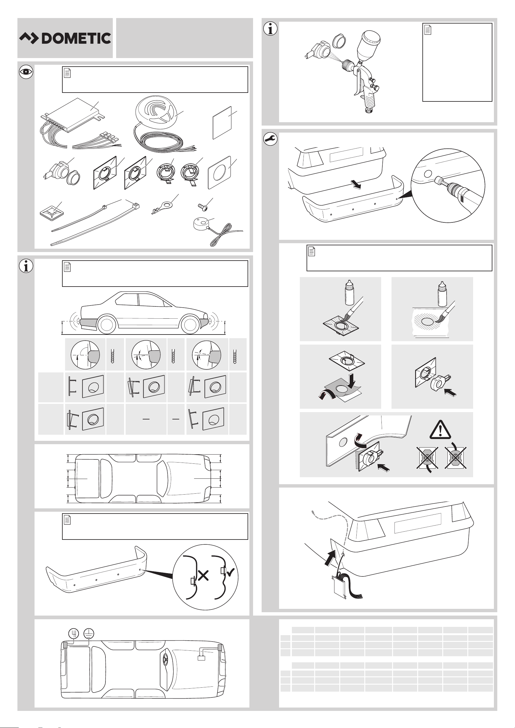
2Scope of delivery
2.1 WPS900F
No. in
fig. 1
1 1 Control electronics 9101500031
2 1 Control unit 9101500032
3 2 Double-sided adhesive tape for control
4 4 Ultrasonic sensors (brown) 9101500058
5 4 Standard 0° sensor holder
6 4 Standard 12° sensor holder
7 4 0° sensor holder with cover ring
8 4 12° sensor holder with cover ring
9 5 Double-sided adhesive tape for sensors
10 4 Fastening holder
11 10
12 1 Cable lug
Quantity Description Ref. no.
electronics and control unit
(fitted from the inside)
(fitted from the inside)
9101500004
(fitted from the outside)
(fitted from the outside)
Cable binder, small
1
Cable binder, large
13 1 Screw
14 1 External button 9103555920
5

EN
Scope of delivery WPS900F/WPS 910
2.2 WPS910
No. in
fig. 1
1 2 Control electronics 9101500031
2 1 Control unit 9101500032
3 3 Double-sided adhesive tape for control
42
5 8 Standard 0° sensor holder
6 8 Standard 12° sensor holder
7 8 0° sensor holder with cover ring
8 8 12° sensor holder with cover ring
9 9 Double-sided adhesive tape for sensors
10 8 Fastening holder
11 20
Quantity Description Ref. no.
electronics and control unit
Ultrasonic sensors (blue)
2
4
2
Ultrasonic sensors (black)
Ultrasonic sensors (brown)
(fitted from the inside)
(fitted from the inside)
(fitted from the outside)
(fitted from the outside)
Cable binder, small
Cable binder, large
9101500057
9101500056
9101500058
9101500004
12 1 Cable lug
13 1 Screw
14 1 External button 9103555920
6

EN
WPS900F/WPS910 Intended use
2.3 Accessories for WPS900F/WPS910
Available as accessories (not included in the scope of delivery):
Description Ref. no.
Sensor holder with silicon ring for metal bumper 9101500015
(VPE 4)
20° sensor holder with cover ring (fitted from outside) 9101500023
(VPE 1)
Sensor extension cable 1.5 m 9103555747
Punching tool 22 mm 9101500024
Punching tool 18 mm 9101500013
3 Intended use
MagicWatch WPS 900F (ref. no. 9600000356) and WPS910 (ref. no. 9600000357)
are ultrasonic radio-based parking aids. When manoeuvring, they monitor the space
in front of or behind the vehicle and emit an audible warning signal if they detect an
obstacle.
MagicWatch is designed for installation in passenger vehicles with a width of up to
2.20 m.
7

EN
Pre-installation instructions WPS900F/WPS910
4 Pre-installation instructions
4.1 Connection options
MagicWatch WPS900F and MagicWatch WPS 910 can process either digital speed
signals from the CAN bus (CAN bus connection on the loudspeaker) or an analogue
speed signal (analogue connection on the front control electronics) to activate the
front parking aid. A CAN bus connection is not possible in all vehicles with a CAN
bus.
NOTE for vehicles with CAN bus
I
• The vehicle-specific product overview on the homepage will tell you
whether a CAN bus connection is possible your vehicle.
“http://www.dometic.de/product/waeco-magicwatch-wps910”,
or call us and ask (for the contact information, please see the back of
the instructions).
• If your vehicle features a CAN bus, but the vehicle list states that a
CAN bus connection is not possible, MagicWatch WPS900F or
WPS910 must be connected using a analogue connector. This will
require analogue transmission of the speed signal.
If the vehicle does not provide a speed signal which is compatible (neither by CAN
bus nor analogue), the front parking aid must be activated and deactivated using the
timer function or the switch (see chapter “Setting the system” on page 14).
8

EN
WPS900F/WPS910 Pre-installation instructions
4.2 Determining the sensor installation position
See fig. 2 to fig. 5
NOTE
I
Note the following during installation:
• The distance from the sensors to the ground should be at least 40 cm and a
maximum of 50 cm (fig. 2).
• For the sensors to function optimally, the angle of the sensor to the road surface
should be 90° (fig. 2). The angle may not be less than 90°, as the road will otherwise be interpreted by the sensor as an obstacle.
• The sensor holders included are suitable for all standard bumpers. Should the
vehicle bumper be mounted at a steep angle, 20° sensor holders with a cover
ring are available as an optional extra (see chapter “Accessories for
WPS900F/WPS910” on page 7).
• The sensor holders included are not suitable for installation in metal bumpers. If
your vehicle has metal bumpers, you will need special sensor holders with a
silicon ring (see chapter “Accessories for WPS900F/WPS910” on page 7).
• Note that the sensor holder depends on the installation height and the angle of
the bumper. Select the right sensor holder and the appropriate drill diameter by
consulting the table in fig. 2. The instruction manual shows how to install the
standard sensor holder (fitted from the inside of the bumper), which produces
the best visual result. Alternatively, the sensors can also be fitted using the sensor
holders with cover ring which are provided.
• Install the sensors in the correct position (fig. 5):
The sensors must be correctly aligned for the device to work properly.
If they point to the ground, irregularities and bumps on the surface may
be interpreted as obstacles. If they point too far up, obstacles will not be
detected at all.
Colour of sensor Installation location
Blue (bl) Outer sides of the rear bumper
Black (sw) Middle sensors on the rear bumper
Brown (br) Front bumper
9

EN
Fitting the parking aid WPS900F/WPS910
4.3 Painting the sensors
See fig. 6
NOTE
I
The sensors may be painted. The manufacturer recommends having the
sensors painted by a specialist workshop.
5 Fitting the parking aid
NOTICE!
A
See fig. 7 to fig. b
Supplements fig. 8
A
On vehicles which feature metal reinforcement behind the bumpers, the
sensors must not be touching this reinforcement. Otherwise there is no
guarantee the parking aid will function correctly.
NOTICE! Risk of malfunction!
Align and attach the sensor holders correctly. Otherwise there is no
guarantee the parking aid will function correctly.
The sensor holders must be attached with the retaining tabs pointing up
and down.
➤ Clean the adhesive surface on the inner side of the bumper with a primer.
➤ Apply a small amount of grease inside the sensor plug connections.
Supplements fig. a
Both the control electronics have been configured for front sensors by default.
Define the control electronics for the rear sensors as follows:
➤ Disconnect the cable bridges.
10

EN
WPS900F/WPS910 Connecting the parking aid
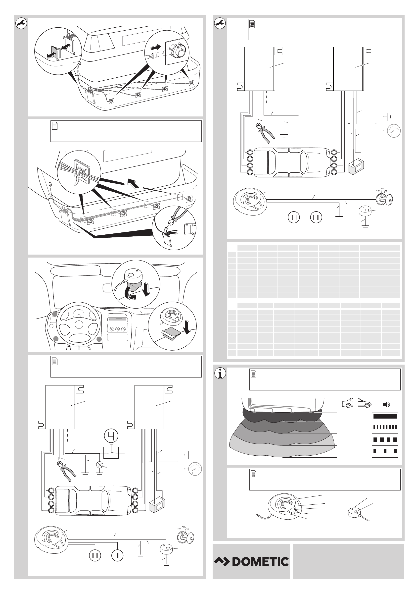
6 Connecting the parking aid
NOTE
I
• On some vehicles, the reversing light only works when the ignition is
switched on. In this case, you must switch on the ignition in order to
identify the positive and earth wires.
• You can set a switch-off time for the front system if you are unable to
provide a speedometer signal for the front sensor control electronics
(neither a digital connection via the CAN bus nor an analogue connection from the speedometer) (see chapter “Programming the system” on page 16 and fig. i, parameter 1).
• You can connect the control electronics for the rear sensors directly
to the continuous operating voltage or to the positive cable for the
ignition (fig. d) if you are unable to provide a reversing signal for the
rear sensor control electronics (e.g. +12 V contact voltage from the
reversing light). This is only an option if you use the CAN bus connection to the control unit, and the vehicle CAN bus provides the reversing signal (see vehicle-specific product overview on the homepage
“http://www.dometic.de/product/waeco-magicwatch-wps910”).
• A reversing signal is not provided via CAN bus on all vehicles which
allow a CAN bus connection.
11

EN
Connecting the parking aid WPS900F/WPS 910
The complete circuit diagram can be found in:
• fig. c for reversing signal via reverse gear
• fig. d for reversing signal via CAN bus
No. Description
1 Control electronics for rear sensors
2 Control electronics for front sensors
3 Black/blue cable: connection to the reversing light
4 Reversing light
5 Brown cable: Connection to earth
6 Black cable bridge (connected = front unit/disconnected = rear unit)
7 Rear sensors
8 Front sensors
9 Brown cable: connection to the negative battery terminal.
10 Black/blue cable: connection to the positive battery terminal.
11 Yellow/black wire (for the front system only): Connection to earth
Optional: connection to the speed signal from the speedometer
12 Black/blue cable: connection to connected positive (+12 V)
13 Black/red wire for the control unit: connection to the black/red wire of the external
button
14 External button
15 Black wire from the external button: connection to earth
16 Brown cable: connection to earth
17 Orange/brown wire: connection to CAN Low
18 Orange/green wire: connection to CAN High
19 Control unit
12

EN
WPS900F/WPS910 Detection range
7Detection range
See fig. e
The detection range of the parking aid is divided into four zones
(The figure applies accordingly for the front sensors):
• Zone 1
This zone is the first limit range. Small objects or those with poor reflective
characteristics may not be detected here.
• Zone 2
Nearly all objects in this zone are displayed.
• Zone 3
Nearly all objects in this zone are displayed, however objects may only appear in
the sensors’ blind spot, or not be detected at all due to their consistency or small
size.
• Stop zone (4)
If there are objects in this zone, the parking aid emits a continuous tone warning
you to stop.
Nearly all objects in this zone are displayed, however objects may only appear in
the sensors’ blind spot or not be detected at all due to their consistency or small
size.
The distance at which the parking aid starts signalling you to stop can be set to
different levels.
The display of fixed objects, such as a trailer hitch, can be suppressed.
13

EN
Setting the system WPS900F/WPS910
8 Setting the system
NOTICE!
A
I
8.1 Control elements
The control unit features the following control elements:
Incorrect settings can impair the operational safety.
NOTE
To stop setting the parameters without saving your changes, or to
stop the entire set-up: refrain from pressing any buttons for a while.
No. in fig. f Description
1 Left button
2 Red LED
3 Yellow LED
4 Right button
5 Loudspeaker
The external button features the following control elements:
No. in fig. f Description
6 LED
7 Button
14

EN
WPS900F/WPS910 Setting the system
8.2 Learning the system
NOTE
I
The system communicates by radio contact. The control unit must be programmed
to ensure it recognises the codes from the other devices.
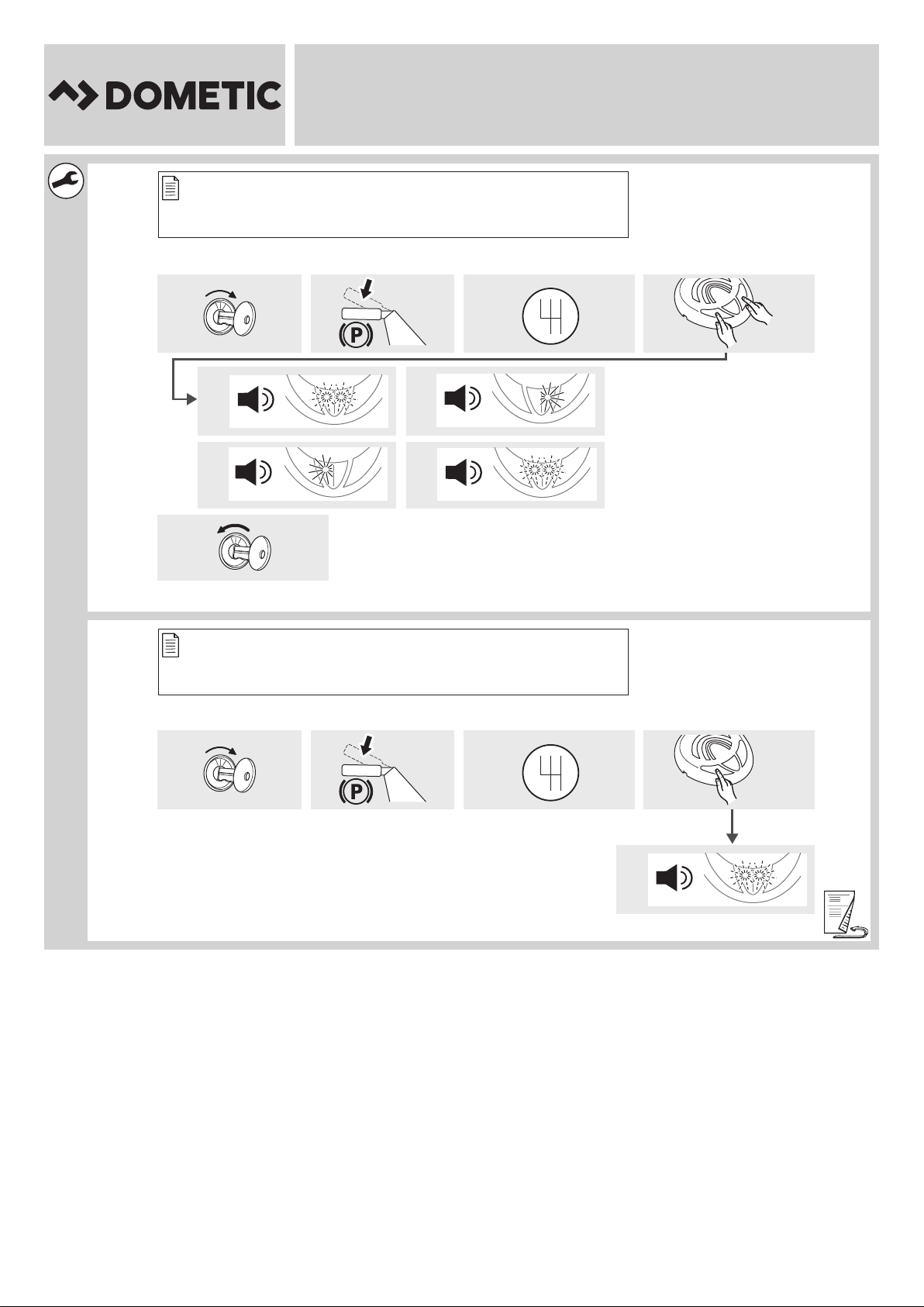
See fig. g
Start the programming procedure as follows:
➤ Connect the voltage supply for the front control electronics.
➤ Switch on the ignition.
➤ Release the handbrake.
➤ Engage the reverse gear.
➤ Press the left and right button on the control unit simultaneously for 5 seconds.
✓ The loudspeaker will emit two tones and the red and yellow LEDs will light up
twice.
You must carry out the learning procedure within 4 minutes of activating
the front sensors. Once these 4 minutes have elapsed, the front system
will stop sending an ID code.
➤ Let go of the two buttons.
➤ Wait for a high-pitched tone and for the yellow LED to light up.
➤ WPS910 only: Wait for a low-pitched tone and for the red LED to light up.
➤ Wait for the loudspeaker to emit three tones and for the yellow and red LED to
light up three times.
➤ Switch the ignition off.
15

EN
Setting the system WPS900F/WPS910
8.3 Programming the system
NOTE
I
You can programme diverse settings.
See fig. h
➤ Start programming as follows:
– Switch on the ignition.
– Release the handbrake.
– Engage reverse gear.
– Press the left button on the control unit for 5 seconds.
The loudspeaker emits a peep tone once, and both LEDs light up.
➤ Set the preferred value (fig. i; chapter “Programming functions” on page 17).
The right button of the remote control is used to set the tens, and the left button
is used to set the units for the preferred value. For example, if you wish to set the
function “24”, press the right button twice and the left button four times.
➤ Once you have set the desired value, wait until the loudspeaker beeps in accord-
ance with the value you have set and the respective LED flashes accordingly.
Adapt the programming of the parameters to the type of installation you
have carried out.
➤ Switch the ignition off.
Configuring the front sensors
The front parking aid is always activated when you:
• Switch on the ignition
• Release the handbrake
• Engage the reverse gear (WPS910 only)
• Briefly press the right button on the loudspeaker (< 5 seconds)
• Press the external button (< 5 seconds)
16

EN
WPS900F/WPS910 Setting the system
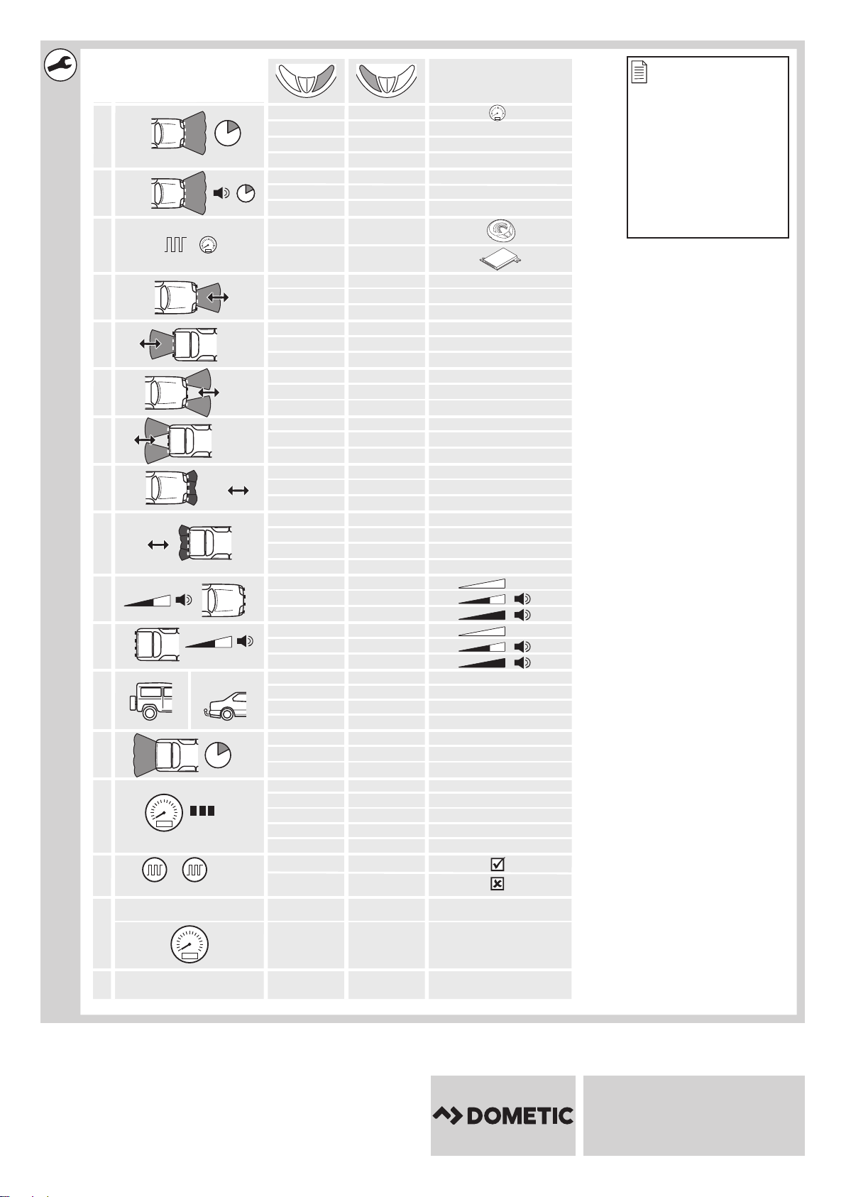
Programming functions
You can also set the function for the front sensors by programming it once, using the
following method, among others (see fig. i):
NOTE
I
• Parameter 1: Speed signal/time-out front sensors (function 13 – 16)
Default setting: speed-dependent
Function 13 (speed-dependent) is set by default. If there is no speed signal avail-
able which is compatible, you have the alternative of using the time-out to deactivate the front parking aid. Once activated, the programmed time period starts
counting down.
If there is an obstacle in the detection range when the time period is over, the
front parking aid remains active. Only when no obstacle is detected for more
than 5 s will the front parking aid shut down.
• Parameter 2: Duration of the front sensor signal
Default setting: 1 sec.
• Parameter 3: Choose the speed signal source
Default setting: Control unit
• Parameter 4: Detection range of the inner front sensors
Default setting: 80 cm
• Parameter 5: Detection range of the inner rear sensors
Default setting: 160 cm
• Parameter 6: Detection range of the outer front sensors
Default setting: 55 cm
• Parameter 7: Detection range of the outer rear sensors
Default setting: 55 cm
• Parameter 8: Stop zone for front sensors
Default setting: Corner sensors = 25 cm, middle sensors = 35 cm
• Parameter 9: Stop zone for rear sensors
Default setting: 35 cm
• Parameter 10: Volume of warning tones for front sensors
Default setting: High
• Parameter 11: Volume of warning tones for rear sensors
Default setting: High
The default settings are printed in bold in the table fig. i.
17

EN
Setting the system WPS900F/WPS910
• Parameter 12: Suppress display of fixed objects
Default setting: Off
• Parameter 13: Shut-down delay for rear sensors
Default setting: Off
• Parameter 14: Number of speed signal pulses
Default setting: 3
• Parameter 15: CAN bus status
Default setting: On
• Parameter 16: City function (function 66) or speed-dependent activation and
deactivation (function 67)
Default setting: Speed-dependent activation and deactivation
Speed-dependent activation and deactivation (function 67)
The default setting automatically activates the front parking aid at speeds below
10 km/h and automatically deactivates at speeds above 10 km/h. Connecting a
compatible speed signal is essential for this function to work.
City function (function 66)
This function deactivates the front parking aid the first time a speed of 10 km/h is
exceeded and does not activate it again when the speed falls below 10 km/h. It
is only activated:
– the next time the reverse gear is engaged
– when the right button on the loudspeaker is pressed
– when the external button is pressed (< 5 s)
The next time the ignition is started, the initial 10 km/h limit is activated again.
Connecting a compatible speed signal is essential for this function.
This function is useful when, for example, the parking aid is considered a
nuisance while driving in city traffic when roads are full, or in traffic jams.
• Parameter 17: Reset to default settings
18

EN
WPS900F/WPS910 Testing functions
9 Testing functions
Complete the functional test of the rear sensors as follows:
➤ Release the handbrake.
➤ Switch on the ignition and engage the reverse gear.
Be very careful when you use the device for the first time, and make sure that you
familiarize yourself with the various sequences of beeps (see fig. e).
NOTICE!
A
Test the front sensors the same way. To do so, drive slowly, for example, towards
a wall.
In zone 4, some obstacles may not be detected, because they are no
longer within range of the sensors (construction-related characteristic).
10 Using the parking aid
The rear sensors are automatically activated when you engage the reverse gear
when the ignition is on or the engine is running.
The front sensors are activated automatically:
• by starting the vehicle
• by engaging the reverse gear
• by lowering the vehicle speed to less than 10 km/h
• by pressing the right button on the control unit
• by pressing the external switch
When the front sensors are activated, the LED on the external button and the
yellow LED on the control unit both light up.
If the speedometer signal cannot be detected, the front sensors are activated when
the ignition is switched on. Once the adjustable switch-off time has elapsed, they are
deactivated automatically.
As soon as there is an obstacle within the detection range, a steady signal tone is
emitted repeatedly.
As you approach, the tone sequence will change according to the zone in which the
obstacle is, thereby indicating the distance (fig. e applies to the front sensors).
Be very careful the first time you use the system, until you are familiar with the various
sequences of beeps.
19

EN
Using the parking aid WPS900F/WPS910
The front sensors are deactivated when
• the speed of the vehicle is more than 10 km/h
• you press the external button or the right button on the control unit briefly
Press one of the two button for at least 5 s to deactivate the front sensors until the
next time the vehicle is started.
NOTICE!
A
A
Stop the vehicle immediately and investigate the situation (getting out
if necessary), if the following happens while you are manoeuvring:
the device first indicates an obstacle and the tone sequence speeds up
normally (e.g. from slow to medium) when manoeuvring. The signal
tone suddenly slows down, or no obstacle is indicated at all.
This means that the original obstacle is in the blind spot of the sensors
(construction-related characteristic), and there is still a potential for collision.
NOTICE!
Be especially careful when manoeuvring after the system has been disconnected from the front or rear sensors.
The system will indicate this fault by:
• the speaker will emit a double alarm tone.
• the red LED in the control unit and the LED on the external button
flash continuously.
I
20
NOTE
When the stop zone is reached, the volume of the continuous tone will
fall by about 50 % after a short time.

EN
WPS900F/WPS910 Troubleshooting
11 Troubleshooting
The device shows no function.
The cables to the reversing light are not connected or are not properly connected.
The plugs for the sensors are not connected or are not correctly plugged into the
control electronics.
➤ Check the plugs and make sure they lock into place.
The speaker emits a double alarm tone, and the red LED in the control unit
and the LED on the external button flash continuously
The system has been disconnected from the front or rear sensors. This can occur due
to interference in the frequency range. Reprogramme the control modules (see
chapter “Learning the system” on page 15).
Audible error signal is emitted for three seconds after engaging the
reverse gear, following by a sequence of tones.
One or more sensors are defective or no longer connected to the control
electronics. The LEDs in the control unit and the LED on the external button are
flashing rapidly. The sequence of tones following the continuous tone indicate
which sensor is defective:
• high tones for the front sensors
(e.g. two high tones for front sensor no. 2)
• low tones for the rear sensors
(e.g. three deep tones for front sensor no. 3)
The sensor with the shortest cable is sensor no. 1, the one with the longest cable is
sensor no. 4.
➤ Check the plugs and make sure they lock into place.
➤ Replace the defective sensor(s).
NOTICE!
A
The system does not work if one or more sensors are defective.
21

EN
Troubleshooting WPS 900F/WPS910
The front sensors shut down too early
The front sensors shut down before the speed reaches 10 km/h. The LEDs in the
control unit and on the external button switch off.
➤ Set parameter 14 (“number of speed signal pulses”) to function “59”, “61”, “62”
or “63” (see chapter “Programming the system” on page 16).
Device indicates obstacles incorrectly
False alarms may have the following causes:
• Dirt or frost on the sensors
➤ Clean the sensors.
• Rain
➤ Check whether the front sensors are deactivated at a speed exceeding 10 km/h.
➤ Check whether a compatible speed signal is available.
If there is no speed signal available, set parameter 1 (“Speed signal/Time-out
front sensors”) to function “14”, “15” or “16” (see chapter “Programming the
system” on page 16).
• The sensors were incorrectly installed.
➤ Adjust the position or height of the sensors (fig. 2).
➤ Make sure that the appropriate sensor bracket was used (0°/12°/20°/bracket
for metal bumpers).
• The sensors are in contact with the chassis.
➤ Separate the sensors from the chassis.
No acoustic signal.
➤ Check whether the yellow LED in the control unit and the LED on the external but-
ton light up.
When the LEDs are flashing, the system is in emergency mode.
Start the vehicle again.
Objects on the vehicle (e.g. spare wheel) result in false alarms.
➤ Set parameter 12 (“Suppress display of fixed objects”) to function “52”, “53” or
“54” (see chapter “Programming the system” on page 16).
22

EN
WPS900F/WPS910 Guarantee
12 Guarantee
The statutory warranty period applies. If the product is defective, please contact the
manufacturer's branch in your country (see the back of the instruction manual for the
addresses) or your retailer.
For repair and guarantee processing, please send the following items:
• Defect components
• A copy of the receipt with purchasing date
• A reason for the claim or description of the fault
13 Disposal
➤ Place the packaging material in the appropriate recycling waste bins wherever
possible.
If you wish to finally dispose of the product, ask your local recycling centre
or specialist dealer for details about how to do this in accordance with the
M
applicable disposal regulations.
23
EN
Technical data WPS900F/WPS910
12
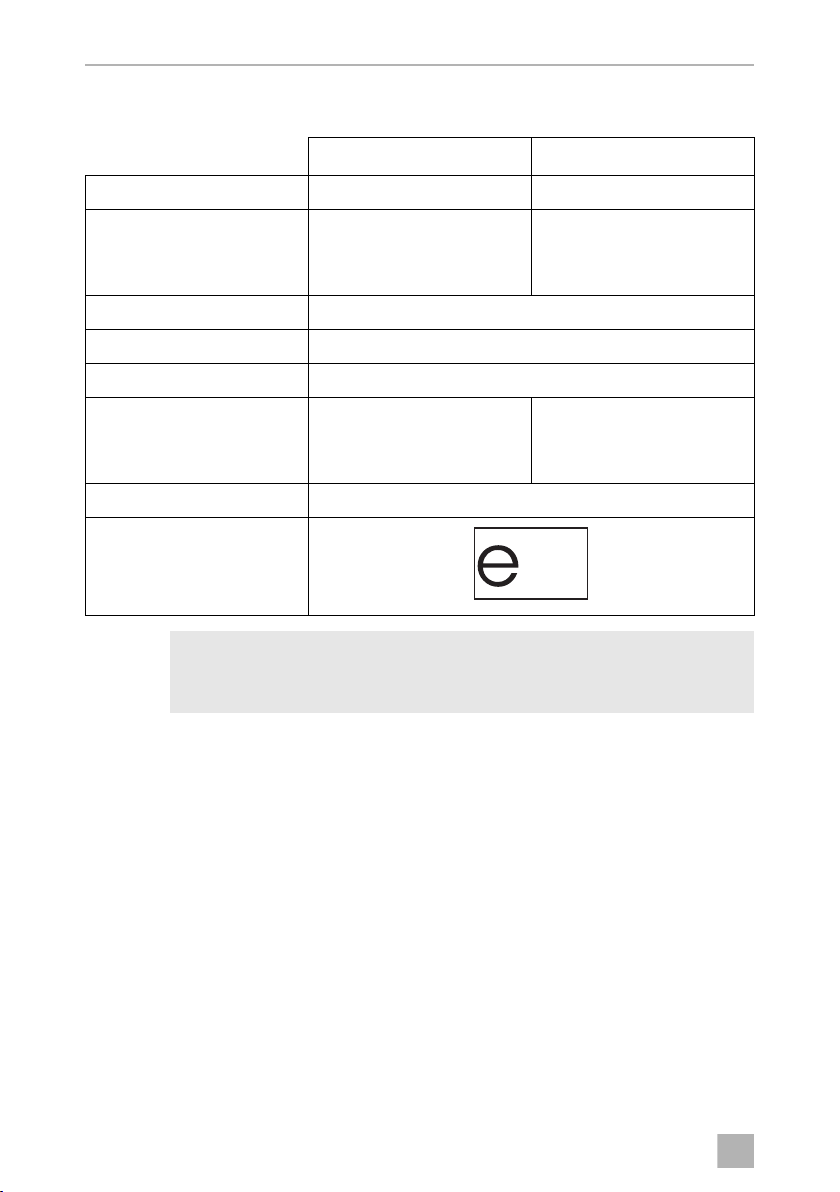
14 Technical data
MagicWatch WPS900F MagicWatch WPS910
Reference no.: 9600000356 9600000357
Detection range
Stop zone:
Measuring range:
Ultrasound frequency: 40 kHz
Transmission frequency: 868 kHz
Supply voltage: 9 – 30 V
Current consumption
Operating:
Standby:
Operating temperature: –25 °C to +70 °C
Certification:
Approx. 0.1 m to 0.25 m
Approx. 0.25 m to 0.9 m
Max. 180 mA
8.5 mA
Approx. 0.1 m to 0.3 m
Approx. 0.3 m to 1.8 m
Max. 240 mA
8.5 mA
I
24
NOTE
The sensors may be painted. The manufacturer recommends having the
sensors painted by a specialist workshop.

DE
WPS900F/WPS910
Bitte lesen Sie diese Anleitung vor Einbau und Inbetriebnahme sorgfältig
durch und bewahren Sie sie auf. Geben Sie sie im Falle einer Weitergabe
des Produktes an den Nutzer weiter.
Inhaltsverzeichnis
1 Sicherheits- und Einbauhinweise . . . . . . . . . . . . . . . . . . . . . . . . . . . . . . . . . 26
2 Lieferumfang . . . . . . . . . . . . . . . . . . . . . . . . . . . . . . . . . . . . . . . . . . . . . . . . . 27
3 Bestimmungsgemäßer Gebrauch . . . . . . . . . . . . . . . . . . . . . . . . . . . . . . . . 29
4 Hinweise vor dem Einbau. . . . . . . . . . . . . . . . . . . . . . . . . . . . . . . . . . . . . . . 30
5 Einparkhilfe montieren . . . . . . . . . . . . . . . . . . . . . . . . . . . . . . . . . . . . . . . . . 32
6 Einparkhilfe anschließen . . . . . . . . . . . . . . . . . . . . . . . . . . . . . . . . . . . . . . . . 33
7 Erfassungsbereich. . . . . . . . . . . . . . . . . . . . . . . . . . . . . . . . . . . . . . . . . . . . . 35
8 System einstellen. . . . . . . . . . . . . . . . . . . . . . . . . . . . . . . . . . . . . . . . . . . . . . 36
9 Funktion testen . . . . . . . . . . . . . . . . . . . . . . . . . . . . . . . . . . . . . . . . . . . . . . . .41
10 Einparkhilfe benutzen . . . . . . . . . . . . . . . . . . . . . . . . . . . . . . . . . . . . . . . . . . . 41
11 Fehler suchen . . . . . . . . . . . . . . . . . . . . . . . . . . . . . . . . . . . . . . . . . . . . . . . . 43
12 Gewährleistung. . . . . . . . . . . . . . . . . . . . . . . . . . . . . . . . . . . . . . . . . . . . . . . 45
13 Entsorgung . . . . . . . . . . . . . . . . . . . . . . . . . . . . . . . . . . . . . . . . . . . . . . . . . . 45
14 Technische Daten . . . . . . . . . . . . . . . . . . . . . . . . . . . . . . . . . . . . . . . . . . . . . 46
25

DE
Sicherheits- und Einbauhinweise WPS900F/WPS910
1 Sicherheits- und Einbauhinweise
Die folgenden Texte ergänzen lediglich die Abbildungen auf dem Beiblatt.
Sie alleine sind keine vollständigen Einbau- und Bedienhinweise! Bitte
beachten Sie unbedingt die Abbildungen auf dem Beiblatt!
Beachten Sie die vom Fahrzeughersteller und vom Kfz-Handwerk vorgeschriebenen Sicherheitshinweise und Auflagen!
Der Hersteller übernimmt in folgenden Fällen keine Haftung für Schäden:
• Beschädigungen am Produkt durch mechanische Einflüsse und Überspannungen
• Veränderungen am Produkt ohne ausdrückliche Genehmigung vom Hersteller
• Verwendung für andere als die in der Anleitung beschriebenen Zwecke
• Bei Fahrzeugen mit LED-Rücklichtern kann der Einbau der Einparkhilfe
zu Störungen führen.
A
• Bei Fahrzeugen mit einem außen angebrachten Ersatzrad oder eine
raußen angebrachten Abschleppstange beachten Sie bitte die Einstellparameter in Kapitel „System einstellen“ auf Seite 36.
• Wenn Sie die Sensoren in Metall-Stoßfänger montieren möchten,
benötigen Sie geeignete Adapter (nicht im Lieferumfang enthalten).
• Beachten Sie die geltenden gesetzlichen Vorschriften.
• Befestigen Sie die im Fahrzeug montierten Teile der Einparkhilfe so,
dass sie sich unter keinen Umständen (scharfes Abbremsen, Verkehrsunfall) lösen und zu Verletzungen der Fahrzeuginsassen führen
können.
• Montieren Sie die im Fahrzeug montierten Teile der Einparkhilfe nicht
im Wirkungsbereich eines Airbags. Sonst besteht Verletzungsgefahr,
wenn der Airbag auslöst.
• Die Sensoren dürfen keine Signallampen verdecken.
• Achten Sie bei der Montage der Sensoren darauf, dass sich keine am
Fahrzeug festangebauten Objekte im Frontbereich und keine zu großen festangebauten Objekte im Heckbereich (z. B. Fahrradträger) im
Erfassungsbereich der Sensoren befinden.
• Die Einparkhilfe soll Sie zusätzlich unterstützen, d. h. das Gerät
entbindet Sie nicht von Ihrer besonderen Vorsichtspflicht beim
Rangieren.
26
 Loading...