

ENDEFR
ES
PTITNLDASV
NO
FIRUPLSKCS
HU
DRIVING SUPPORT
PERFECTVIEW
VT100DIG
Digital radio link
Installation and Operating Manual . . . . . . 7
Digitale Funkstrecke
Montage- und Bedienungsanleitung . . . 19
Systéme radio numérique
Instructions de montage
et de service . . . . . . . . . . . . . . . . . . . . . . . 32
Tramo de transmisión por radio
digital
Instrucciones de montaje y de uso . . . . . 45
Percurso digital
Instruções de montagem e manual de
instruções . . . . . . . . . . . . . . . . . . . . . . . . . 58
Tratta radio digitale
Istruzioni di montaggio e d’uso . . . . . . . . 71
Digitaal zendbereik
Montagehandleiding en
gebruiksaanwijzing. . . . . . . . . . . . . . . . . . 84
Digital trådløs forbindelse
Monterings- og betjeningsvejledning. . . 97
Digital radiolänk
Monterings- och bruksanvisning . . . . . . 109
Digital radiolink
Monterings- og bruksanvisning . . . . . . .121
Digitaalinen radiolinkki
Asennus- ja käyttöohje. . . . . . . . . . . . . . 133
Устройство цифровой
радиосвязи
Инструкция по монтажу
и эксплуатации. . . . . . . . . . . . . . . . . . . . 146
Cyfrowe łącze radiowe
Instrukcja montażu i obsługi . . . . . . . . . 160
Digitálne rádiorelé spojenie
Návod na montáž a uvedenie
do prevádzky . . . . . . . . . . . . . . . . . . . . . 173
Zařízení k přenosu digitálního
rádiového signálu
Návod k montáži a obsluze . . . . . . . . . . 186
Digitális rádiós szakasz
Szerelési és használati útmutató . . . . . . 198

VT100DIG
1
2
3
4
9
6 8
5
7
10
11
12
1
3
2
3
2.
1.
1.
4
12
5
VT100DIG
4
VT100DIG
65
7 8
4
1
2
3
6
1
2
3
5
6
4
7
5
VT100DIG
8
9
6

VT100DIG Explanation of symbols
EN
Please read this instruction manual carefully before installati on and first use, and store
it in a safe place. If you pass on the product to another person, hand over this instruction manual along with it.
Table of contents
1 Explanation of symbols. . . . . . . . . . . . . . . . . . . . . . . . . . . . . . . . . . . . . . . . . . . . . . . . . . . . . . . 7
2 Safety and installation instructions . . . . . . . . . . . . . . . . . . . . . . . . . . . . . . . . . . . . . . . . . . . . . .8
3 Scope of delivery . . . . . . . . . . . . . . . . . . . . . . . . . . . . . . . . . . . . . . . . . . . . . . . . . . . . . . . . . . 10
4 Intended use . . . . . . . . . . . . . . . . . . . . . . . . . . . . . . . . . . . . . . . . . . . . . . . . . . . . . . . . . . . . . . 10
5 Technical description . . . . . . . . . . . . . . . . . . . . . . . . . . . . . . . . . . . . . . . . . . . . . . . . . . . . . . . 10
6 Installing the radio link . . . . . . . . . . . . . . . . . . . . . . . . . . . . . . . . . . . . . . . . . . . . . . . . . . . . . . 12
7 Connecting electrical power to the radio link . . . . . . . . . . . . . . . . . . . . . . . . . . . . . . . . . . . . 13
8 Pairing the system . . . . . . . . . . . . . . . . . . . . . . . . . . . . . . . . . . . . . . . . . . . . . . . . . . . . . . . . . . 16
9 Troubleshooting . . . . . . . . . . . . . . . . . . . . . . . . . . . . . . . . . . . . . . . . . . . . . . . . . . . . . . . . . . . 17
10 Warranty . . . . . . . . . . . . . . . . . . . . . . . . . . . . . . . . . . . . . . . . . . . . . . . . . . . . . . . . . . . . . . . . . 17
11 Disposal. . . . . . . . . . . . . . . . . . . . . . . . . . . . . . . . . . . . . . . . . . . . . . . . . . . . . . . . . . . . . . . . . . 18
12 Technical data . . . . . . . . . . . . . . . . . . . . . . . . . . . . . . . . . . . . . . . . . . . . . . . . . . . . . . . . . . . . . 18
1 Explanation of symbols
WARN ING !
!
!
Safety instruction: Failure to observe this instruction can cause fatal or serious injury.
CAUTION!
Safety instruction: Failure to observe this instruction can lead to injury.
A
I
NOTICE!
Failure to observe this instruction can cause material damage and impair the function
of the product.
NOTE
Supplementary information for operating the product.
7

Safety and installation instructions VT100DIG
EN
2 Safety and installation instructions
The manufacturer accepts no liability for da mage in the following cases:
• Damage to the product resulting from mechanical influences and excess voltage
• Alterations to the product without express permission from the manufacturer
• Use for purposes other than those described in the operating manual
Please observe the prescribed safety instructions and stipulations from the vehicle
manufacturer and service workshops.
WARN ING !
Inadequate supply cable connections could result in short circuits, which could have as
!
a consequence that:
• Cable fires occur
• The airbag is triggered
• Electronic control devices are damaged
• Electric functions fail (indicators, brake light, horn, ignition, lights)
NOTICE!
To prevent the risk of short circuits, always disconnect the negative terminal of the vehi-
A
cle's electrical system before working on it.
If the vehicle has an additional battery, its negative terminal should also be disconnected.
Please observe the following instructions:
• When working on the following cables, only use insulated cable lugs, plugs and flat push-on
recepta cles:
– 30 (direct supply from positive battery terminal)
–15 (connected positive terminal, behind the battery)
– 31 (return line from the battery, earth)
– L (indicator lights left)
– R (indicator lights right)
Do not use terminal strips.
• Use a crimping tool to connect the cables.
• When connecting to cable 31 (earth), screw the cable
– to the vehicle's earth bolt with a cable lug and a gear disc or
– to the sheet-metal bodywork with a cable lug and a self-tapping screw.
Ensure that there is a good earth connection.
8

VT100DIG Safety and installation instructions
EN
If you disconnect the negative terminal of the battery, all data stored in the volatile memories will
be lost.
• The following data must be set again, depending on the vehicle equipment options:
–Radio code
– Vehicle clock
–Timer
– On-board computer
– Seat position
You can find instructions for making these settings in the appropriate operating instructions.
Observe the following installation instructions:
CAUTION!
• Secure the parts installed in the vehicle in such a way that they cannot become loose
!
A
Observe the following instructions when working with electrical parts:
A
under any circumstances (sudden braking, accidents) and cause injuries to the
occupants of the vehicle.
• Secure any parts of the system covered by the bodywork in such a manner that they
cannot be come loose or damage other parts and cables or impair vehicle functions
(steering, pedals, etc).
• Always follow the safety instructions of the vehicle manufacturer.
Some work (e.g. on retention systems such as the AIRBAG etc.) may only be performed by qualified specialists.
NOTICE!
• To prevent damage when drilling, make sure there is sufficient space on the other
side for the drill head to come out.
• Deburr all drill holes and treat them with a rust-protection agent.
NOTICE!
• When testing the voltage in electrical cables, only use a diode test lamp or a voltmeter.
Test lamps with an illuminant take up voltages which are too high and which can damage the vehicle's electronic system.
• When making electrical connections, ensure that:
– they are not kinked or twisted
– they do not rub on edges
– they are not laid in sharp edged ducts without protection.
• Insulate all connection s.
• Secure the cables against mechanical wear with cable binders or insulating tape,
for example to existing cables.
9

Scope of delivery VT100DIG
EN
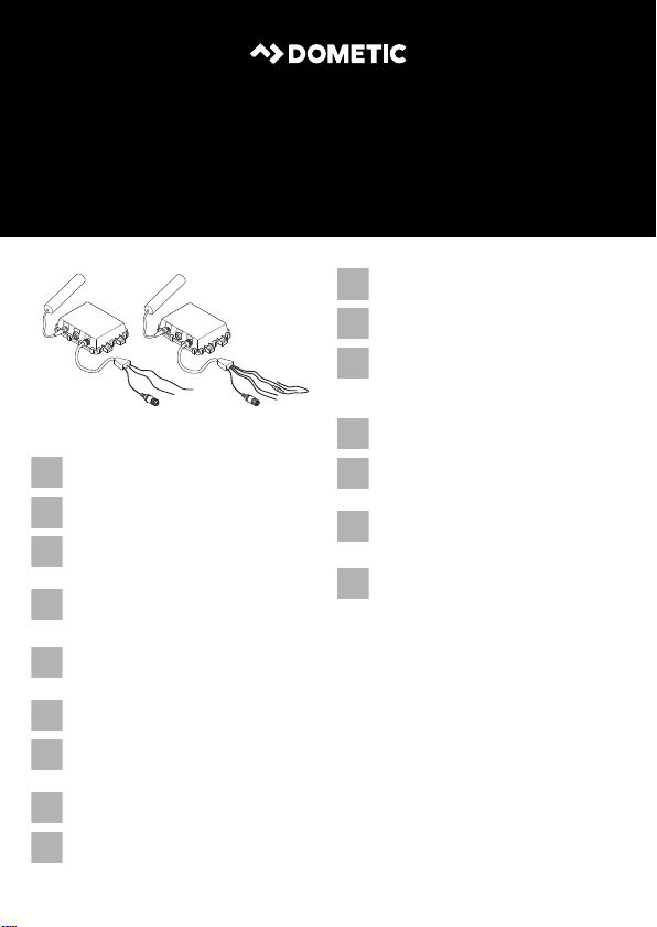
3Scope of delivery
No. in
fig. 5, page 4
1 1 Transmitter module
21Receiver module
––Fastening material
Quantity Description
4Intended use
The PerfectView VT100DIG radio link (ref. no. 9600000068) is used for the wireless transmission
of signals between the camera and the monitor for the PerfectView reversing video systems from
2011.
5 Technical description
5.1 Function description
The radio link consists of a transmitter module and a receiver module. The two modules can be
mounted inside or outside the vehicle. They transmit pictures and sound wirelesssly from the
camera to the monitor.
The transmitter module is preferably supplied with a voltage via the ignition plus and is also used
to supply the camera with a voltage. When connecting only with the reversing light, the system
pairing cannot be started in reverse gear.
The receiver module is powered by the monitor. The wireless signals are transmitted in the
2.4 GHz range.
Since the system is designed merely as an additional aid for reversing, it does not relieve you of
the duty to take proper care when reversing.
NOTICE!
A
• VT100DIG transmits digital data. The data is displayed on the monitor 0.2 s after it
is recorded by the camera. Therefore, it is essential that you drive slowly.
• If the monitor displays a yellow warning triangle, there is a fault in the picture
transmission. It is possible that the display of the camera image on the monitor is
delayed. Therefore the system may not be used as an aid during reversing in such
circumstances.
10

VT100DIG Technical description
EN
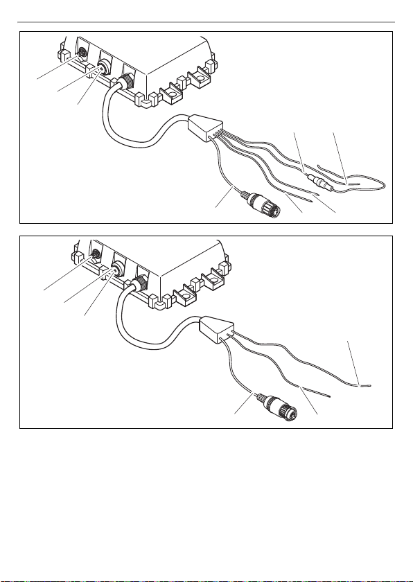
5.2 Control elements
You will find the following control elements on the transmitter module:
No. in
fig. 6, page 5
1 Antenna connection
2 Pairing button
3 Operating mode display:
4 Camera connection
5 Blue cable (CAMERA POWER TRIGGER): voltage supply for camera and
6 Green cable (REVERSE TRIGGER): control cable for activating the pairing
7 Red cable (DC INPUT): Connection to the positive terminal of the
8 Black cable (GND): Connection to the negative terminal of the voltage
The receiver module has the following control elements:
No. in
fig. 7, page 5
1 Antenna connection
2 Pairing button
3 Operating mode display:
4 Monitor connection
5 Green cable (REVERSE TRIGGER): control cable for activating the pairing
6 Black cable (GND): Connection to earth
Meaning
• LED glows red when signals are being transmitted
• LED flashes red when the components are being paired
switch input for protective cover of CAM80 (see page 15)
signal
voltage supply; preferably ignition plus
supply or earth
Meaning
• LED glows red when signals are being transmitted
• LED flashes red when the components are being paired
signal
11

Installing the radio link VT100DIG
EN
6 Installing the radio link
6.1 Tools required
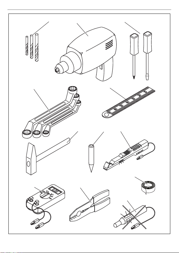
For installation and assembly, you will need the following tools:
• Drill bit set (fig. 1 1, page 3)
• Electric drill (fig. 1 2, page 3)
• Screwdriver (fig. 1 3, page 3)
• Set of ring or open-ended spanners (fig. 1 4, page 3)
• Measuring ruler (fig. 1 5, page 3)
• Hammer (fig. 1 6, page 3)
• Centre punch (fig. 1 7, page 3)
To establish and test the electrical connection, the following tools are required:
• Diode test lamp (fig. 1 8, page 3) or voltmeter (fig. 1 9, page 3)
• Crimping tool (fig. 1 10, page 3)
• Insulating tape (fig. 1 11, page 3)
• Cable bushing sleeves (optional)
To fasten the module and the cables, you may need additional screws and cable binders.
6.2 Installing the modules
CAUTION!
!
Observe the following installation instructions:
• Install the modules so that as few objects as possible are between them.
• If possible, install the modules in the vehicle.
• The installation location should be flat.
• Before drilling, check each time that there is sufficient space on the other side for the drill head
• Transmitter module: Make sure you can lay the connection cable to the camera.
• Receiver module: Make sure you can lay the connection cable to the monitor.
12
Select the location of the modules so that they cannot injure the passengers in the
vehicle under any circumstances (e.g. sudden braking, road traffic accidents).
Metal objects in particular can hinder radio transmission.
The housings are splash-water protected and can be mounted outside the vehicle. In this
case, you need to select a location that is protected against mechanical impacts (e.g. flying
stones).
to emerge (fig. 2, page 4).

VT100DIG Connecting electrical power to the radio link
EN
NOTE
I
To perform the installation, proceed as follows:
➤ Attach the modules temporarily to the planned installation location.
➤ Install the rear view video system if you have not already done so.
➤ Start up the rear view video system.
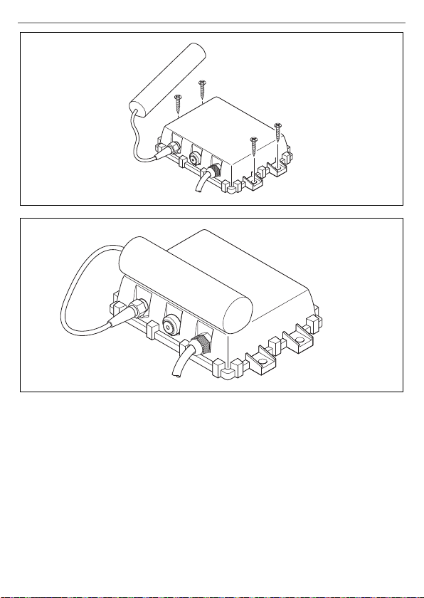
Attaching the modules (fig. 8, page 6)
To do this, proceed as follows for each module:
➤ Hold the module at the chosen location and mark the four points for drill holes.
➤ Drill holes with a Ø of 4 mm at each of the points you just marked.
➤ Screw the module on with M5 x 20mm self-tapping screws.
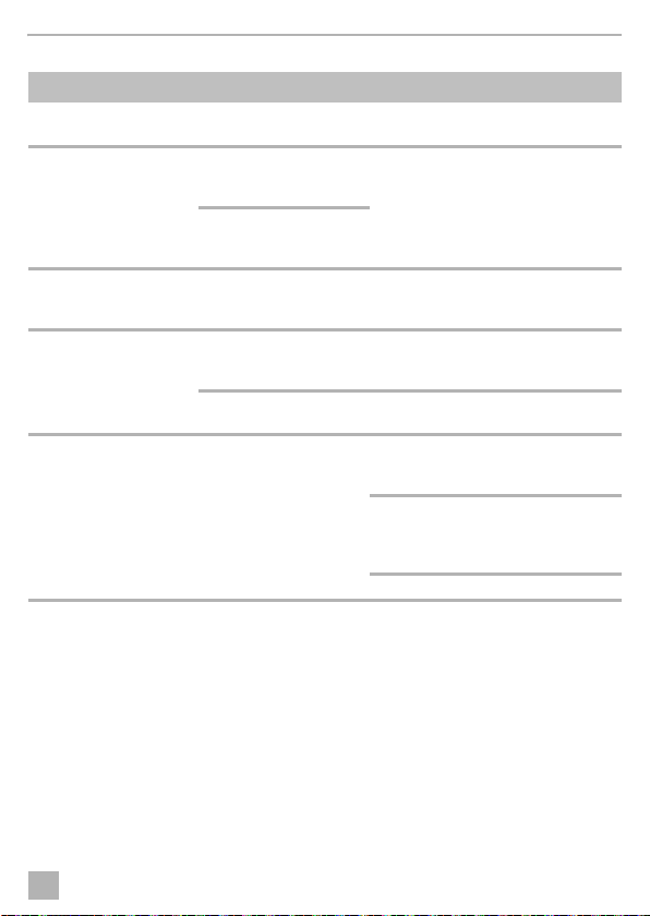
Fixing the antennas (fig. 9, page 6)
I
➤ You can glue the antennae on the corresponding module.
Pictures and sound are sent from the transmitter module to the receiver module. To
ensure flawless functio ning, you need to check whether the wireless transmission is
stable before final installation.
If the camera image transmission is stable (two or three reception bars at the top right of the
monitor), you can complete final installation of the two modules.
If faults occur (only one reception bar or a yellow warning triangle on the top right of the
monitor) turn or move the transmitter or receiver module slightly and conduct further tests.
NOTE
Always align the antennas in the same direction, for example, both vertically.
This improves the transmission performance.
7 Connecting electrical power to the radio link
7.1 General notes on laying cables
I
NOTE
• As far as possible, use original ducts for laying the cables, or other suitable options
such as panelling edges, ventilation grilles or dummy plugs. If no openings are available, you must drill holes for the cables. Check beforehand that there is sufficient
space on the other side for the drill head to emerge.
• Cables and connections that are not properly installed will cause malfunctions or
damage to components. Correct installation of cables and connections ensures
lasting and trouble-free operation of the retrofitted components.
13

Connecting electrical power to the radio link VT 100DIG
EN
Therefore, please observe the following instructions:
• Wherever possible, lay cables inside the vehicle, as they are better protected there than
outside.
If you do need to lay a cable outside the vehicle, ensure that it is well fastened (use additional
cable ties, insulating tape etc.).
• To prevent damage to the cables when laying them, ensure that they are far enough away from
hot or moving vehicle components (exhaust pipes, drive shafts, light systems, fans, heaters
etc.).
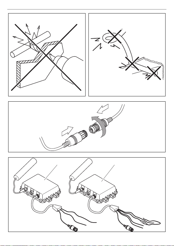
• Screw on the plug connections of the connecting cables to protect against water penetration
(fig. 4, page 4).
• When laying the cables, make sure:
– they are not kinked or twisted
– they do not rub on edges
– they are not laid in sharp-edged ducts without protection (fig. 3, page 4).
• Protect every through-hole made in the bodywork against water penetration, e.g. by using a
cable with a sealant and by spraying the cable and the cable sleeve with sealant.
NOTE
I
7.2 Connecting electrical power to the transmitter module
A
VT100DIG requires a few seconds to initiate the digital wireless connection. To keep this start-up
time short, you should connect the transmitter module to an active +12 V voltage supply. If no
continuous operating voltage is available, you can connect the transmitter module to the reversing
light.
Connecting the transmitter module to a continuous operating voltage
➤ Connect the red cabl e of the transmitter module (fig. 6 7, page 5) to an active positive cable,
➤ Connect the black cable of the transmitter module (fig. 6 8, page 5) to earth (bodywork).
➤ Connect the green cable of the transmitter module (fig. 6 6, page 5) to the reversing light.
A
Only start sealing through-holes when you have completed all installation work on the
camera and have laid the required cable lengths.
NOTICE!
Make sure the polarity is correct.
e.g. terminal 15.
NOTICE!
Always connect the green cable to the reversing light and not to a continuous
operating voltage or an active positive cable. The "pairing" is started via this cable by
engaging the reverse gear three times.
14

VT100DIG Connecting electrical power to the radio link
EN
➤ Connect the blue cable of the transmitter module (fig. 6 5, page 5) depending on the type
of camera.
– Camera without motorised protective cover to an active positive cable
– Camera with motorised protective cover to the reversing light
➤ Connect the camera connector (fig. 6 4, page 5) to the camera.
Connecting the transmitter module to the reversing light (no continuous operating
voltage)
NOTE
I
➤ Connect the red cable of the transmitter module (fig. 6 7, page 5) to the positive wire (+) of
➤ Connect the black cable of the transmitter module (fig. 6 8, page 5) to the earth wire (–) of
➤ Connect the blue cable of the transmitter module (fig. 6 5, page 5) to the positive wire of the
➤ Connect the camera connector (fig. 6 4, page 5) to the camera.
A
• These connection options only work with the cameras CAM 50C, CAM60CM or
CAM30C.
• On some vehicles, the reversing light only works when the ignition is switched on.
In this case, you must switch on the ignition in order to identify the positive and earth
wires.
• If the transmitter module is o nly connected via the reversing light, the system pairing
cannot be started in the reverse gear.
the reversing light.
the reversing light or to earth (bodywork).
reversing light.
NOTICE!
The green cable may not be used.
Pairing the transmitter and receiver is only possible when reverse gear is engaged via
the button!
7.3 Connecting electrical power to the receiver module
➤ Connect the green cable of the receiver module (fig. 7 5, page 5) to the reversing switch.
➤ Connect the black cable of the receiver module (fig. 7 6, page 5) to earth (bodywork).
➤ Connect the monitor connector (fig. 7 4, page 5) to the monitor.
➤ Switch on the monitor.
✓ The monitor displays the message “Wait Tx Signal …”.
15

Pairing the system VT100DIG
EN
8 Pairing the system
NOTE
I
8.1 Pairing the system manually with the pairing button
➤ Press the pairing button on the receiver module (fig. 7 2, page 5) three times within 10 s
✓ The LED on the receiver module (fig. 7 3, page 5) flashes red.
✓ The monitor displays the message “Pairing Start” and a counter that counts down 50 s.
➤ Press the pairing button on the transmitter module (fig. 6 2, page 5) three times within 10 s
✓ The LED on the transmitter module (fig. 6 3, page 5) flashes red.
✓ The modules synchronise themselves with each other.
8.2 Pairing the system with reverse gear
You can start pairing the module via the reverse gear if you connect the red cable from the transmitter module to the positive terminal and the green cable of both modules on the reversing light.
➤ Switch on the monitor.
➤ Activate the required channel.
➤ Engage and disengage the reverse gear three times within 10 s.
✓ The LED on the transmitter module (fig. 6 3, page 5) and the LED on the receiver module
✓ The modules synchronise themselves with each other.
The transmitter module and the receiver module have to be paire d with each other so
that the monitor can display the camera images. This is conducted at the factory.
(press the button approx. 1 time per second).
You need to perform the pairing of the transmitter module within 50 s.
(press the button approx. 1 time per second).
This takes approx. three to five seconds. For successful pairing, t he monitor shows the “Save
data” message and the picture appears.
If pairing is unsuccessful, the monitor displays the message “Pairing Failed”. Repeat
the pairing procedure.
(fig. 7 3, page 5) flash red.
This takes approx. three to five seconds. For successful pairing, t he monitor shows the “Save
data” message and the picture appears.
If pairing is unsuccessful, the monitor displays the message “Pairing Failed”. Repeat
the pairing procedure.
16
VT100DIG Troubleshooting
EN
9 Troubleshooting
Fault Cause Suggested remedy
The monitor displays the
message “NO SIGNAL”.
The monitor displays the
message “REVERSE
FOR IMAGE”.
The monitor displays the
message “Pairing
Failed”.
The monitor displays the
message “wait for
TX”.
Irregular image playback
or yellow warning triangle
on the screen.
The transmitter module is
not working.
The green and the blue
cable are incorrectly connected.
The transmitter module is
not receiving a video signal.
The start signal (on/off
three times) is incomplete
or missing.
Tra ns mi tte r a nd rece iv er
modules have lost identification.
The transmitter module
has no voltage supply.
– Make sure that the antennae of the
Check the voltage supply.
Check the camera connection and
function.
Repeat the system pairing until the
monitor displays “Save data”.
Engage reverse gear again.
Start system pairing.
Check the voltage supply.
receiver module and the transmitter
module are firmly connected.
Check the reception bars on the monitor. If only one reception bar is displayed, change the position of the
transmitter or receiver module.
Check if the battery charge is sufficient.
10 Warranty
The statutory warranty period applies. If the product is defective, please contact the
manu factu rer's b ranch i n your c ountry (see th e back o f the in struct ion ma nual fo r the ad dresse s) or
your retailer.
For repair and guarantee processing, please include the following documents when you send in
the device:
• A copy of the receipt with purchasing date
• A reason for the claim or description of the fault
17
Disposal VT100DIG
EN
13
1622
10R-0412874
11 Disposal
➤ Place the packaging material in the appropriate recycling waste bins wherever possible.
If you wish to finally dispose of the product, ask your local recycling centre or specialist
dealer for details about how to do this in accordance with the applicable disposal
M
regulat ions.
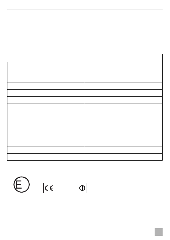
12 Technical data
VT100DIG
Ref. no.: 9600000068
Frequency: 2.400– 2.483 GHz
Transmission output of transmitter module: 10 mW
Reception delay: < 200 ms
Range: 120 m, free field
Channel raster: 18.9 MHz
Frame rate: max. 30 frames/s
Operating temperature: –20 °C to +60 °C
Operating voltage: 12– 30 Vg
Current consumption
Transmitter modul e (without came ra)
Receiver module:
Protection class: IP65
Dimensions (W x H x D) (without antenna): 115 x 110 x 26 mm
Weight: 220 g
Approvals
The appliance has E13 certification.
approx. 130 mA
approx. 100 mA
18

VT100DIG Erklärung der Symbole
DE
Bitte lesen Sie diese Anleitung vor Einbau und Inbetriebnahme sorgfältig durch und
bewahren Sie sie auf. Geben Sie sie im Falle einer Weitergabe des Produktes an den
Nutzer weiter.
Inhaltsverzeichnis
1 Erklärung der Symbole . . . . . . . . . . . . . . . . . . . . . . . . . . . . . . . . . . . . . . . . . . . . . . . . . . . . . . 19
2 Sicherheits- und Einbauhinweise. . . . . . . . . . . . . . . . . . . . . . . . . . . . . . . . . . . . . . . . . . . . . . 20
3 Lieferumfang . . . . . . . . . . . . . . . . . . . . . . . . . . . . . . . . . . . . . . . . . . . . . . . . . . . . . . . . . . . . . . 22
4 Bestimmungsgemäßer Gebrauch . . . . . . . . . . . . . . . . . . . . . . . . . . . . . . . . . . . . . . . . . . . . .22
5 Technische Beschreibung . . . . . . . . . . . . . . . . . . . . . . . . . . . . . . . . . . . . . . . . . . . . . . . . . . .22
6 Funkstrecke montieren . . . . . . . . . . . . . . . . . . . . . . . . . . . . . . . . . . . . . . . . . . . . . . . . . . . . . .24
7 Funkstrecke elektrisch anschließen . . . . . . . . . . . . . . . . . . . . . . . . . . . . . . . . . . . . . . . . . . . . 26
8 System abgleichen . . . . . . . . . . . . . . . . . . . . . . . . . . . . . . . . . . . . . . . . . . . . . . . . . . . . . . . . . 29
9 Störungsbeseitigung . . . . . . . . . . . . . . . . . . . . . . . . . . . . . . . . . . . . . . . . . . . . . . . . . . . . . . .30
10 Gewährleistung . . . . . . . . . . . . . . . . . . . . . . . . . . . . . . . . . . . . . . . . . . . . . . . . . . . . . . . . . . .30
11 Entsorgung . . . . . . . . . . . . . . . . . . . . . . . . . . . . . . . . . . . . . . . . . . . . . . . . . . . . . . . . . . . . . . . 31
12 Technische Daten . . . . . . . . . . . . . . . . . . . . . . . . . . . . . . . . . . . . . . . . . . . . . . . . . . . . . . . . . . 31
1 Erklärung der Symbole
WARN UNG !
!
!
Sicherheitshinweis: Nichtbeachtung kann zu Tod oder schwerer Verletzung führen.
VORSIC HT!
Sicherheitshinweis: Nichtbeachtung kann zu Verletzungen führen.
A
I
ACHTUNG!
Nichtbeachtung kann zu Materialschäden führen und die Funktion des Produktes
beeinträchtigen.
HINWEIS
Ergänzende Informationen zur Bedienung des Produktes.
19

Sicherheits- und Einbauhinweise VT100DIG
DE
2 Sicherheits- und Einbauhinweise
Der Hersteller übernimmt in folgenden Fällen keine Haftung für Schäden:
• Beschädigungen am Produkt durch mechanische Einflüsse und Überspannungen
• Veränderungen am Produkt ohne ausdrückliche Genehmigung vom Hersteller
• Verwendung für andere als die in der Anleitung beschriebenen Zwecke
Beachten Sie die vom Fahrzeughersteller und vom Kfz-Handwerk vorgeschriebenen
Sicherheitshinweise und Auflagen!
WARN UNG !
Unzureichende Leitungsverbindungen können zur Folge haben, dass durch Kurzschluss
!
• Kabelbrände entstehen,
• der Airbag ausgelöst wird,
• elektronische Steuerungseinrichtungen beschädigt werden,
• elektrische Funktionen ausfallen (Blinker, Bremslicht, Hupe, Zündung, Licht).
ACHTUNG!
Klemmen Sie wegen der Kurzschlussgefahr vor Arbeiten an der Fahr zeugelektrik immer
A
den Minuspol ab.
Bei Fahrzeugen mit Zusatzbatt erie müssen Sie an dieser ebenfalls den Minuspol abklemmen.
Beachten Sie deshalb folgende Hinweise:
• Verwenden Sie bei Arbeiten an den folgenden Leitungen nur isolierte Kabelschuhe, Stecker
und Flachsteckhülsen:
– 30 (Eingang von Batterie Plus direkt)
– 15 (Geschaltetes Plus, hinter Batterie)
– 31 (Rückleitung ab Batterie, Masse)
– L (Blinkerleuchten links)
– R (Blinkerleuchten rechts)
Verwen den S ie kein e Lüsterklemmen.
• Verwenden Sie eine Krimpzange zum Verbinden der Kabel.
• Schrauben Sie das Kabel bei Anschlüssen an Leitung 31 (Masse)
– m it Kabelschuh und Zahnscheibe an eine fahrzeugeigene Masseschraube oder
– mit Kabelschuh und Blechschraube an das Karosserieblech.
Achten Sie auf eine gute Masseübertragung!
20

VT100DIG Sicherheits- und Einbauhinweise
DE
Beim Abklemmen des Minuspols der Batterie verlieren alle flüchtigen Speicher der Komfortelektronik ihre gespeicherten Daten.
• Folgende Daten müssen Sie je nach Fahrzeugausstattung neu einstellen:
–Radiocode
–Fahrzeuguhr
– Zeitschaltuhr
– B ordcomputer
– Sitzposition
Hinweise zur Einstellung finden Sie in der jeweiligen Bedienungsanleitung.
Beachten Sie folgende Hinweise bei der Montag e:
VORSIC HT!
• Befestigen Sie die im Fahrzeug montierten Teile so, dass sie sich unter keinen
!
A
Beachten Sie folgende Hinweise bei der Arbeit an elektrischen Teilen:
A
Umständen (scharfes Abbremsen, Verkehrsunfall) lösen und zu Verletzungen der
Fahrzeuginsassen führen können.
• Befestigen Sie verdeckt unter Verkleidungen anzubringende Teile des Systems so,
dass sie sich nicht lösen oder andere Teile und Leitungen beschädigen und keine
Fahrzeugfunktionen (Lenkung, Pedale usw.) beeinträchtigen können.
• Beachten Sie immer die Sicherheitshinweise des Fahrzeugherstellers.
Einige Arbeiten (z. B. an Rü ckhaltesystemen wie Airbag usw.) dürfen nur von geschultem Fachpersonal durchgeführt werden.
ACHTUNG!
• Achten Sie beim Bohren auf ausreichenden Freiraum für den Bohreraustritt, um Schäden zu vermeiden.
• Entgraten Sie jede Bohrung und behandeln Sie diese mit Rostschutzmittel.
ACHTUNG!
• Benutzen Sie zum Prüfen der Spannung in elektrischen Leitungen nur eine Diodenprüflampe oder ein Voltmeter.
Prüflampen mit einem Leuchtkörper nehmen zu hohe Ströme auf, wodurch die Fahrzeugelektronik beschädigt werden kann.
• Beachten Sie beim Verlegen der elektrischen Anschlüsse, dass diese
– nicht geknickt oder verdreht werden,
– nicht an Kanten scheuern,
– nicht ohne Schutz durch scharfkantige Durchführungen verlegt werden.
• Isolieren Sie alle Verbindungen und Anschlüsse.
• Sichern Sie die Kabel geg en mechanische Beanspruchung durch Kabelbinder oder
Isolierband, z. B. an vorhandenen Leitungen.
21

Lieferumfang VT100DIG
DE
3Lieferumfang
Nr. in
Abb. 5, Seite 4
11Sendemodul
2 1 Empfangsmodul
––Befestigungsmaterial
Menge Bezeichnung
4 Bestimmungsgemäßer Gebrauch
Die Funkstrecke PerfectView VT 100DIG (Artikel-Nr. 9600000068) dient zur kabellosen
Übertragung der Signale zwischen Kamera und Monitor für die Rückfahrvideosysteme
PerfectView ab 2011.
5 Technische Beschreibung
5.1 Funktionsbeschreibung
Die Funkstrecke besteht aus einem Sendemodul und einem Empfangsmodul. Die beiden Module
können im oder außen am Fahrzeug m ontiert werden. Sie übertragen Bild und Ton digital per Funk
von der Kamera zum Monitor.
Das Sendemodul wird vorzugsweise über Zündungsplus mit Spannung versorgt und dient
gleichzeitig als Spannungsversorgung für die Kamera. Bei Anschluss nur über den Rückfahrscheinwerfer, kann der Systemabgleich nicht über den Rückwärtsgang gestartet werden.
Das Empfangsmodul erhält die Spannungsversorgung durch den Monitor. Die Funksignale
werden im 2,4-GHz-Bereich übertragen .
Das System stellt eine Unte rstützung beim Rückwärtsfahren dar, es entbindet Sie jedoch nicht von
der besonderen Vorsichtspflicht beim Rückwärtsfahren.
ACHTUNG!
A
• VT100DIG überträgt digitale Daten. Die Darstellung am Monitor ist um 0,2 s
gegenüber der Kameraaufnahme verzögert. Fahren Sie deshalb unbedingt
langsam.
• Wenn der Monitor ein gelbes Warndre ieck anzeigt, ist die Bildübertragung gestört.
Möglicherweise verzögert sich die Darstellung auf dem Monitor zeitlich gegenüber
der Kameraaufnahme. Deshalb darf das System in diesem Fall nicht zur
Absicherung beim Rückwärtsfahren eingesetzt werden.
22
VT100DIG Technische Beschreibung
DE
5.2 Bedienelemente
Am Sendemodul finden Sie folgende Bedienelemente:
Nr. in
Abb. 7, Seite 5
1 Antennen-Anschluss
2 Abgleichtaster
3 Betriebsart-Anzeige:
4 Kamera-Anschluss
5 Blaues Kabel (CAMERA POWER TRIGGER): Spannungsversorgung
6 Grünes Kabel (REVERSE TRIGGER): Steuerleitung zur Aktivierung des
7 Rotes Kabel (DC INPUT): Anschluss an Pluspol der Spannungsquelle;
8 Schwarzes Kabel (GND): Anschluss an Minuspol der Spannungsquelle
Am Empfangsmodul finden Sie folgende Bedienelemente:
Nr. in
Abb. 7, Seite 5
1 Antennen-Anschluss
2 Abgleichtaster
3 Betriebsart-Anzeige:
4 Monitor-Anschluss
5 Grünes Kabel (REVERSE TRIGGER): Steuerleitung zur Aktivierung des
6 Schwarzes Kabel (GND): Anschluss an Masse
Bedeutung
• LED leuchtet rot, wenn Signale übertragen werden
• LED blinkt rot, wenn die Komponenten abgeglichen werden
Kamera und Schalteingang für Schutzklappe von CAM80 (siehe
Seite 27)
Abgleichsignals
vorzugsweise Zündungsplus
oder Masse
Bedeutung
• LED leuchtet rot, wenn Signale übertragen werden
• LED blinkt rot, wenn die Komponenten abgeglichen werden
Abgleichsignals
23

Funkstrecke montieren VT 100DIG
DE
6Funkstrecke montieren
6.1 Benötigtes Werkzeug
Für Einbau und Montage benötigen Sie folgende Werkzeuge:
• Satz Bohrer (Abb. 1 1, Seite 3)
• Bohrmaschine (Abb. 1 2, Seite 3)
• Schraubendreher (Abb. 1 3, Seite 3)
• Satz Ring- oder Maulschlüssel (Abb. 1 4, Seite 3)
• Maßstab (Abb. 1 5, Seite 3)
• Hammer (Abb. 1 6, Seite 3)
• Körner (Abb. 1 7, Seite 3)
Für den elektrischen Anschluss und seine Überprüfung benötigen Sie folgende Hilfsmittel:
• Diodenprüflampe (Abb. 1 8, Seite 3) oder Voltmeter (Abb. 1 9, Seite 3)
• Krimpzange (Abb. 1 10, Seite 3)
• Isolierband (Abb. 1 11, Seite 3)
• Ggf. Kabeldurchführungstüllen
Zur Befestigung der Module und der Kabel benötigen Sie ggf. noch weitere Schrauben und
Kabelbinder.
6.2 Module montieren
VORSIC HT!
!
Beachten Sie folgende Hinweise bei der Montag e:
• Montieren Sie die Module so, dass sich möglichst wenige Objekte zwischen ihnen befinden.
• Montieren Sie die Module möglichst im Fahrzeug.
• Der Montageort sollte eben sein.
• Kontrollieren Sie vor jedem Bohren, ob ausreichender Freiraum für den Bohreraustritt
• Sendemodul: Stellen Sie sicher, dass Sie das Anschlusskabel zur Kamera verlegen können.
Wählen Sie den Platz der Module so aus, dass unter keinen Umständen (z. B. durch
scharfes Abbremsen, Verkehrsunfall) Fahrzeuginsassen verletzt werden können.
Besonders metallische Objekte behindern die Funkübertragung.
Die Gehäuse sind spritzwasse rgeschützt und können außen am Fahrzeug montiert werden. In
diesem Fall müssen Sie einen Ort auswählen, der vor mechanischer Belastung (z. B. Steinschlag) geschützt ist.
vorhanden ist (Abb. 2, Seite 4).
24

VT100DIG Funkstrecke montieren
DE
• Empfangsmodul: Stellen Sie sicher, dass Sie das Anschlusskabel zum Monitor verlegen
können.
HINWEIS
I
Gehen Sie bei der Montage wie folgt vor:
➤ Befestigen Sie die Module provisorisch jeweils am geplanten Montageort.
➤ Montieren Sie ggf. das Rückfahrvideosystem.
➤ Nehmen Sie das Rückfahrvideosystem in Betrieb.
Module befestigen (Abb. 8, Seite 6)
Gehen Sie für jedes Modul wie folgt vor:
➤ Halten Sie das Modul jeweils an den gewählten Montageort und markieren Sie die vier
➤ Bohren Sie an den zuvor angezeichneten Punkten jeweils ein Loch von Ø 4 mm.
➤ Schrauben Sie das Modul mit den Blechschrauben M5 x 20 mm an.
Antennen befestigen (Abb. 9, Seite 6)
I
➤ Sie können die Antennen auf dem zugehörigen Modul ankleben.
Bild und Ton werden vom Sendemodul zum Empfangsmodul übertragen. Für eine
einwandfreie Funktion müssen Sie vor der endgültigen Montage prüfen, ob die
Funkübertragung stabil ist.
Wenn das Kamerabild stabil übertragen wird (zwei oder drei Empfangsbalken oben rechts auf
dem Monitor), können Sie die beiden Module endgültig montieren.
Wenn Störungen auftreten (nur ein Empfangsbalken oder ein gelbes Warndreieck oben
rechts auf dem Monitor), drehen oder versetzen Sie das Sende- oder das Empfangsmodul
leicht und testen Sie es erneut.
Bohrpunkte.
HINWEIS
Montieren Sie die Antennen immer in gleiche Ausrichtung, z. B. beide senkrecht.
Dadurch wird die Übertragungsleistung verbessert.
25

Funkstrecke elektrisch anschließen VT 100DIG
DE
7 Funkstrecke elektrisch anschließen
7.1 Allgemeine Hinweise zur Kabelverlegung
HINWEIS
I
Beachten Sie deshalb folgende Hinweise:
• Verlegen Sie die Kabel nach Möglichkeit immer im Fah rzeuginneren, denn dort sind sie besser
• Um Beschädigungen am Kabel zu vermeiden, halten Sie beim Verlegen der Kabel immer
• Verschrauben Sie die Steckverbindungen der Verbindungskabel zum Schutz gegen das
• Beachten Sie beim Verlegen der Kabel, dass diese
• Schützen Sie jeden Durchbruch an der Auße nhaut durch geeignete Maßnahmen gegen
• Verwenden Sie für die Durchführung der Anschlusskabel nach Möglichkeit
Originaldurchführungen oder andere Durchführungsmöglichkeiten, z. B.
Verkleidungskanten, Lüftungsgitter oder Blindschalter. Wenn keine Durchführungen vorhanden sind, müssen Sie für die jeweiligen Kabel entsprechende
Löcher bohren. Schauen Sie vorher nach, ob ausreichender Freiraum für den
Bohreraustritt vorhanden ist.
• Nicht fachgerechte Kabelverlegungen und Kabelverbindungen führen immer
wieder zu Fehlfunktionen oder Beschädigung en von Bauteilen. Eine korrekte
Kabelverlegung bzw. Kabelverbindung ist die Grundvoraussetzung für eine
dauerhafte und fehlerfreie Funktion der nachgerüsteten Komponenten.
geschützt als außen am Fahrzeug.
Wenn Sie die Kabel trotzdem außerhalb des Fahrzeuges verlegen, achten Sie auf eine sichere
Befestigung (durch zusätzliche Kabelbinder, Isolierband usw.).
ausreichend Abstand zu heißen und sich bewegenden Fahrzeugteilen (Auspuffrohre,
Antriebswellen, Lichtmaschine, Lüfter, Heizung usw.).
Eindringen von Wasser (Abb. 4, Seite 4).
– nicht stark geknickt oder verdreht werden,
–nicht an Kanten scheuern,
– nicht ohne Schutz durch scharfkantige Durchführungen verlegt werden (Abb. 3, Seite 4).
Wassereinbruch, z. B. durch Einsetzen des Kabels mit Dichtungsmasse und durch Abspritzen
des Kabels und der Durchführungstülle mit Dichtungsmasse.
I
26
HINWEIS
Beginnen Sie mit dem Abdichten der Durchbrüche erst, nachdem alle Einstella rbeiten
an der Kamera abgeschlossen sind und die benötigten Längen der Anschlusskabel
festliegen.

VT100DIG Funkstrecke elektrisch anschließen
DE
7.2 Sendemodul elektrisch anschließen
ACHTUNG!
A
VT100DIG benötigt einige Sekunden, um die digitale Funkverbindung aufzubauen. Um diese
Startzeit kurz zu halten, sollten Sie das Sendemodul an eine geschaltete +12-V-Spannungsquelle
anschließen. Wenn keine Dauerspannung zur Verfügung steht, können Sie das Sendemodul an
den Rückfahrscheinwerfer anschließen.
Sendemodul an Dauerspannung anschließen
➤ Schließen Sie das rote Kabel des Sendemoduls (Abb. 6 7, Seite 5) an eine geschaltete
➤ Schließen Sie das schwarze Kabel des Sendemoduls (Abb. 6 8, Seite 5) an Masse
➤ Schließen Sie das grüne Kabel des Sendemoduls (Abb. 6 6, Seite 5) an den Rückfahr-
A
➤ Schließen Sie das blaue Kabel des Sendemoduls (Abb. 6 5, Seite 5) abhängig vom
➤ Verbinden Sie den Kamera-Anschluss (Abb. 6 4, Seite 5) mit der Kamera.
Achten Sie auf die richtige Polung.
Plusleitung an, z. B. an Klemme 15.
(Karosserie) an.
scheinwerfer an.
ACHTUNG!
Schließen Sie das grüne Kabel immer am Rückfahrscheinwerfer an, nicht an
Dauerspannung oder an eine geschaltete Plusleitung. Über diese Leitung wird durch
dreimaliges Einlegen des Rückwärtsganges das „pairing“ gestartet.
Kameratyp an:
– Kamera ohne motorbetriebene Schutzklappe an geschaltete Plusleitung
– Kamera mit motorbetriebener Schutzklappe an Rückfahrscheinwerfer
27

Funkstrecke elektrisch anschließen VT 100DIG
DE
Sendemodul an den Rückfahrscheinwerfer anschließen (keine Dauerspannung)
HINWEIS
I
➤ Schließen Sie das rote Kabel des Sendemoduls (Abb. 6 7, Seite 5) an die Plusleitung (+) des
➤ Schließen Sie das schwarze Kabel des Sendemoduls (Abb. 6 8, Seite 5) an die
➤ Schließen Sie das blaue Kabel des Sendemoduls (Abb. 6 5, Seite 5) an die Plusleitung des
➤ Verbinden Sie den Kamera-Anschluss (Abb. 6 4, Seite 5) mit der Kamera.
A
7.3 Empfangsmodul elektrisch anschließen
➤ Schließen Sie das grüne Kabel des Empfangsmoduls (Abb. 7 5, Seite 5) an den
➤ Schließen Sie das schwarze Kabel des Empfangsmoduls (Abb. 7 6, Seite 5) an Masse
➤ Verbinden Sie den Monitor-Anschluss (Abb. 7 4, Seite 5) mit dem Monitor.
➤ Schalten Sie den Monitor ein.
✓ Der Monitor zeigt die Meldung „Wait Tx Signal …“.
• Bei dieser Anschlussvariante können nur die Kameras CAM50C, CAM 60CM oder
CAM30C eingesetzt werden.
• Bei manchen Fahrzeugen funktioniert der Rückfahrscheinwerfer nur bei
eingeschalteter Zündung. In diesem Fall müssen Sie die Zündung einschalten,
um die Plus- und die Masseleitung zu bestimmen.
• Wenn Sie das Sendemodul nur über den Rückfahrscheinwerfer anschließen,
kann der Systemabgleich nicht über den Rückwärtsgang gestartet werden.
Rückfahrscheinwerfers an.
Masseleitung (–) des Rückfahrscheinwerfers oder an Masse (Karosserie) an.
Rückfahrscheinwerfers an.
ACHTUNG!
Das grüne Kabel darf nicht verwendet werden.
Das Abgleichen von Sender und Empfänger ist nur bei eingelegtem Rückwärtsgang
über die Taster möglich!
Rückfahrschalter an.
(Karosserie) an.
28

VT10 0DIG System abgleichen
DE
8System abgleichen
HINWEIS
I
8.1 System manuell mit dem Abgleichtaster abgleichen
➤ Drücken Sie den Abgleichtaster am Empfangsmodul (Abb. 7 2, Seite 5) innerhalb von 10 s
✓ Die LED am Empfangsmodul (Abb. 7 3, Seite 5) blinkt rot.
✓ Der Monitor zeigt die Meldung „Pairing Start“ und einen Zähler, der einen Countdown
➤ Drücken Sie den Abgleichtaster am Sendemodul (Abb. 6 2, Seite 5) innerhalb von 10 s
✓ Die LED am Sendemodul (Abb. 6 3, Seite 5) blinkt rot.
✓ Die beiden Module stellen sich aufeinander ein.
8.2 System mit dem Rückwärtsgang abgleichen
Sie können den Abgleich der Module über den Rückwärtsgang starten, wenn Sie die rote Leitung
des Sendemoduls an geschaltetes Plus und die grüne Leitung beider Module am Rückfahrscheinwerfer anschließen.
➤ Schalten Sie den Monitor ein.
➤ Aktivieren Sie den entsprechenden Kanal.
➤ Legen Sie den Rückwärtsgang innerhalb von 10 s dreimal ein und aus.
✓ Die LED am Sendemodul (Abb. 6 3, Seite 5) und die LED am Empfangsmodul (Abb. 7 3,
✓ Die beiden Module stellen sich aufeinander ein.
Das Sendemodul und Empfangsmodul müssen aufeinander abgestimmt sein, damit
der Monitor das Bild von der Kamera übertragen kann.
Dies wurde werksseitig durchgeführt.
dreimal (ca. 1 Tastendruck pro Sekunde).
von 50 s hinunterzählt.
Sie müssen den Abgleich des Sendemoduls innerhalb dieser 50 s vornehmen.
dreimal (ca. 1 Tastendruck pro Sekunde).
Dies dauert ca. drei bis fünf Sekunden. Bei erfolgreichem Abgleich zeigt der Monitor die
Meldung „Save data“ und das Bild erscheint.
Bei erfolglosem Abgleich zeigt der Monitor die Meldung „Pairing Failed“.
Wiederholen Sie den Abgleich.
Seite 5) blinken rot.
Dies dauert ca. drei bis fünf Sekunden. Bei erfolgreichem Abgleich zeigt der Monitor die
Meldung „Save data“ und das Bild erscheint.
Bei erfolglosem Abgleich zeigt der Monitor die Meldung „Pairing Failed“.
Wiederholen Sie den Abgleich.
29
Störungsbeseitigung VT100DIG
DE
9 Störungsbeseitigung
Störung Ursache Lösungsvorschlag
Der Monitor zeigt die
Meldung „NO SIGNAL“.
Der Monitor zeigt die
Meldung „REVERSE
FOR IMAGE“.
Der Monitor zeigt die
Meldung „Pairing
Failed“.
Der Monitor zeigt die
Meldung „wait for
TX“.
Stockende Bildwiedergabe oder gelbes
Warndreieck auf dem
Bildschirm.
Das Sendemodul arbeitet
nicht.
Das grüne und blaue
Kabel sind falsch
angeschlossen.
Das Sendemodul erhält
kein Videosignal.
Das Startsignal (dreimal
Ein/Aus) ist unvollständig
oder fehlt.
Sende- und Empfangsmodul haben die
Kennung verlo ren.
Das Sendemodul hat
keine Spannung.
– Stellen Sie sicher, dass die Antennen
Prüfen Sie die Spannungsversorgung.
Prüfen Sie Anschluss und Funktion der
Kamera.
Wiederholen Sie den Systemabgleich
bis der Monitor „Save data“
anzeigt.
Legen Sie noch einmal den Rückwärtsgang ein.
Starten Sie den Systemabgleich.
Prüfen Sie die Spannungsversorgung.
des Empfangsmoduls und des
Sendemoduls fest angeschlossen sind.
Prüfen Sie die Empfangsbalken auf
dem Monitor. Wenn nur ein Balken
angezeigt wird, ändern Sie die Position
des Sende- oder des Empfangsmoduls.
Prüfen Sie, ob die Batterieladung
ausreichend ist.
10 Gewährleistung
Es gilt die gesetzliche Gewährleistungsfrist. Sollte das Produkt defekt sein, wenden Sie sich bitte
an die Niederlassung des Herstellers in Ihrem Land (Adressen siehe Rückseite der Anleitung) oder
an Ihren Fachhändler.
Zur Reparatur- bzw. Gewährleistungsbearbeitung müssen Sie folgende Unterlagen mitschicken:
• eine Kopie der Rechnung mit Kaufdatum,
• einen Reklamationsgrund oder eine Fehlerbeschreibung.
30

VT100DIG Entsorgung
DE
13
1622
10R-0412874
11 Entsorgung
➤ Geben Sie das Verpackungsmaterial möglichst in den entsprechenden Recycling-Müll.
Wenn Sie das Produkt endgültig außer Betrieb nehmen, informieren Sie sich bitte beim
nächsten Recyclingcenter oder bei Ihrem Fachhändler über die zutreffenden
M
Entsorgungsvorschriften.
12 Technische Daten
VT100DIG
Artikelnummer: 9600000068
Frequenz: 2,400– 2,483 GHz
Sendeleistung Sendemodul: 10 mW
Empfangsverzögerung: < 200 ms
Reichweite: 120 m, Freifeld
Kanalraster: 18,9 MHz
Bildrate: max. 30 Bilder/s
Betriebstemperatur: –20 °C bis +60 °C
Betriebsspannung: 12 –30 Vg
Stromverbrauch
Sendemodul (ohne Kamera):
Empfangsmodul:
Schutzklasse: IP65
Abmessungen B x H x T (ohne Antenne): 115 x 110 x 26 mm
Gewicht: 220 g
Zulassungen
Das Gerät hat die E13-Zulassung.
ca. 130 mA
ca. 100 mA
31

Explication des symboles VT100DIG
FR
Veuillez lire attentivement cette notice avant le montage et la mise en service. Veuillez
ensuite la conserver. En cas de passer le produit, veuillez le transmettre au nouvel
acquéreur.
Sommaire
1 Explication des symboles . . . . . . . . . . . . . . . . . . . . . . . . . . . . . . . . . . . . . . . . . . . . . . . . . . . .32
2 Consignes de sécurité et instructions de montage. . . . . . . . . . . . . . . . . . . . . . . . . . . . . . . . 33
3 Pièces fournies . . . . . . . . . . . . . . . . . . . . . . . . . . . . . . . . . . . . . . . . . . . . . . . . . . . . . . . . . . . . 35
4 Usage conforme . . . . . . . . . . . . . . . . . . . . . . . . . . . . . . . . . . . . . . . . . . . . . . . . . . . . . . . . . . . 35
5 Description technique . . . . . . . . . . . . . . . . . . . . . . . . . . . . . . . . . . . . . . . . . . . . . . . . . . . . . .35
6 Montage du système radio . . . . . . . . . . . . . . . . . . . . . . . . . . . . . . . . . . . . . . . . . . . . . . . . . . 37
7 Raccordement électrique du système radio . . . . . . . . . . . . . . . . . . . . . . . . . . . . . . . . . . . . .39
8 Réglage du système . . . . . . . . . . . . . . . . . . . . . . . . . . . . . . . . . . . . . . . . . . . . . . . . . . . . . . . .42
9 Dépannage . . . . . . . . . . . . . . . . . . . . . . . . . . . . . . . . . . . . . . . . . . . . . . . . . . . . . . . . . . . . . . . 43
10 Garantie. . . . . . . . . . . . . . . . . . . . . . . . . . . . . . . . . . . . . . . . . . . . . . . . . . . . . . . . . . . . . . . . . . 43
11 Retraitement . . . . . . . . . . . . . . . . . . . . . . . . . . . . . . . . . . . . . . . . . . . . . . . . . . . . . . . . . . . . . .44
12 Caractéristiques techniques. . . . . . . . . . . . . . . . . . . . . . . . . . . . . . . . . . . . . . . . . . . . . . . . . .44
1 Explication des symboles
AVERTISSEMENT !
!
!
Consigne de sécurité : le non-respect de ces consignes peut entraîner la mort ou de
graves blessures.
ATTENTION !
Consigne de sécurité : le non-respect de ces consignes peut entraîner des bles-
sures.
A
I
32
AVIS !
Le non-respect de ces consigne s peut entraîner des dommages matériels et des dysfonctionnements du produit.
REMARQUE
Informations complémentaires sur l'utilisation du produit.

VT100DIG Consignes de sécurité et instructions de montage
FR
2 Consignes de sécurité et instructions de montage
Le fabricant décline toute responsabilité pour des dommages dans les cas suivants :
• des influences mécaniques et des surtensions ayant endommagé le matériel
• des modifications apportées au produit sans autorisation explicite de la part du fabricant
• une utilisation différente de celle décrite dans la notice
Respectez les consignes de sécurité et autres prescriptions imposées par le fabricant
du véhicule et par les professionnels de l'automobile !
AVERTISSEMENT !
Tout branchement électrique inadéquat peut entraîner un court-circuit causant
!
• la combustion de câbles,
• le déclenchement de l'airbag,
• l’endommagement des dispositifs électroniques de commande,
• la défaillance des fonctions électriques (clignotants, feux-stop, klaxon, allumage,
éclairage).
AVIS !
Débranchez toujours la borne négative avant de procéder à des travaux sur les éléments
A
électriques du véhicule afin d’éviter tout risque de court-circuit.
Sur les véhicules équipés d’une batterie supplémentaire, vous devez également
débrancher le pôle négatif de cette dernière.
Veuillez donc respecter les consignes suivantes :
• Pour tous les travaux sur les lignes électriques suivantes, n’utilisez que des cosses de câble,
fiches et alvéoles pour contacts plats isolés :
– 30 (entrée directe pôle positif de la batterie)
–15 (pôle positif connecté, derrière la batterie)
– 31 (ligne de retour à partir de la batterie, masse)
– L (clignotants gauches)
– R (clignotants droits)
N’utilisez pas de dominos.
• Utilisez une pince à sertir pour relier les câbles.
• Pour les raccordements à la ligne électrique 31 (masse), vissez le câble
– à une vis de masse du véhicule, avec une cosse et une rondelle crantée, ou bien
– à la carrosserie, avec une cosse et une vis à tôle.
Veillez à une bonne transmission de la masse !
33

Consignes de sécurité et instructions de montage VT100DIG
FR
Lorsque vous débranchez le pôle négatif de la batterie, les mémoires volatiles de l’électronique de
confort perdent toutes les données enregistrées.
• Vous devez procéder à un nouveau réglage des données suivantes en fonction de l’équipement du véhicule :
–code radio
– horloge du véhicule
–minuterie
– ordinateur de bord
– position du siège
Les instructions de réglage figurent dans les notices d’utilisation correspondantes.
Veuillez respecter les consignes suivantes lors du montage :
ATTENTION !
• Fixez les pièces installées dans le véhicule de manière à ce qu’elles ne puissent en
!
A
Veuillez respecter les consignes suivantes pour les travaux sur les éléments électriques :
A
aucun cas se desserrer (freinage abrupt, accident) et risquer de causer des blessures
aux occupants du véhicule.
• Fixez les pièces du système sous l'habillage de telle sorte qu'elles ne puissent pas se
détacher, endommager d'autres pièces ou connexions, ni gêner le fonctionnement
du véhicule (direction, pédales, etc.).
• Respectez toujours les co nsignes de sécurité du fabricant du véhicule.
Certains travaux (p. ex. au niveau des systèmes de retenue, AIRBAG, etc.) doivent
être effectués uniquement par un personnel spécialisé ayant reçu une formation correspondante.
AVIS !
• Avant de percer des trous, assurez-vous que vous disposez d’un espace suffisant de
l'autre côté du trou à percer afin que la mèche n'occasionne aucun dégât.
• Ebavurez tous les trous et protégez-les avec un enduit anticorrosif.
AVIS !
• Pour le contrôle de la tension des lignes électriques, n’utilisez qu’une lampe étalon à
diode ou un voltmètre.
Les lampes étalons à corps lumineux absorbent des courants trop élevés qui pourraient endommager les composants électroniques du véhicule.
• Lors de l'installation des raccordements électriques, veillez à ce que ceux-ci
– ne soient ni pliés, ni tordus,
– ne frottent pas contre des arêtes,
– ne soient pas placés dans des passages à arêtes vives sans protection.
• Isolez toutes les connexions et tous les raccords.
• Protégez les câbles contre toute contrainte mécanique en les fixant par exemple aux
lignes existantes à l'aide de serre-câbles ou de ruban vinyle.
34

VT100DIG Pièces fournies
FR
3Pièces fournies
N° dans
fig. 5, page 4
1 1 Module émetteur
2 1 Module récepteur
– – Matériel de fixation
Quantité Désignation
4Usage conforme
Le système radio PerfectView VT 100DIG (n° d’art. 9600000068) permet la transmission sans fil
des signaux entre la caméra et le moniteur pour le s systèmes vidéo de recul PerfectView à partir de
2011.
5 Description technique
5.1 Description du fonctionnement
Le système radio se compose d’un module ém etteur et d’un module récepteur. Les deux modules
peu vent être m onté s dan s le v éhicu le ou à l’e xtéri eur, sur le véhicule. Ils transmettent image et son
par radio, de la caméra à l’écran, de manière numérique.
Le module émetteur est alimenté de préférence par le pôle positif de l'allumage et sert en même
temps d'alimentation en tension pour la caméra. En cas de raccordement uniquement par le feu
de recul, il n'est pas possible de démarrer le réglage du système par la marche arrière.
L’alimentation électrique du module récepteur a lieu par le moniteur. Les signaux radio sont
transmis sur 2,4 GHz.
Le système vous apporte une aide supplémentaire en marche arrière, mais cet a ppareil ne vous dispense pas du devoir de prudence qui vous incombe alors.
AVIS !
A
• VT100DIG transmet des données numériques. La représentation à l’écran est
décalée de 0,2 s par rapport à l’enregistrement de la caméra. Vous devez donc
absolument rouler lentement.
• Lorsque l’écran affich e un triangle jaune, la transmis sion de l’image est défectueus e.
Il est probable que la représentation à l’écran soit décalée dans le temps par
rapport à l’enregistrement de la caméra. C’est pourquoi le système ne doit pas
être utilisé dans ce cas comme protection en marche arrière.
35

Description technique VT100DIG
FR
5.2 Éléments de commande
Le module émetteur est équipé des éléments de commande suivants :
N° dans
fig. 6, page 5
1 Raccordement de l’antenne
2Touche de réglage
3 Affichage du mode de fonctionnement :
4 Raccordement de la caméra
5 Câble bleu (CAMERA POWER TRIGGER) : alimentation électrique de la
6 Câble vert (REVERSE TRIGGER) : ligne de commande pour l'activation
7 Câble rouge (DC INPUT) : raccordement au pôle positif de la source de
8 Câble noir (GND) : raccordement au pôle négatif de la source de ten-
Le module récepteur est équipé des éléments de commande suivants :
N° dans
fig. 7, page 5
1 Raccordement de l’antenne
2Touche de réglage
3 Affichage du mode de fonctionnement :
4 Raccordement du moniteur
5 Câble vert (REVERSE TRIGGER) : ligne de commande pour l'activation
6 Câble noir (GND) : raccordement à la masse
Signification
• la DEL s’allume en rouge lors de la transmission des signaux
• la DEL clignote en rouge lors du réglage des composants
caméra et entrée de commutation pour le clapet de protection de la
CAM80 (voir page 40)
du signal de réglage
tension ; de préférence pôle positif de l’allumage
sion ou à la masse
Signification
• la DEL s’allume en rouge lors de la transmission des signaux
• la DEL clignote en rouge lors du réglage des composants
du signal de réglage
36

VT100DIG Montage du système radio
FR
6 Montage du système radio
6.1 Outils nécessaires
Pour la mise en place et le montage, vous devez disposer des outils suivants :
• Jeu de mèches (fig. 1 1, page 3)
• Perceuse (fig. 1 2, page 3)
• Tournevis (fig. 1 3, page 3)
• Jeu de clés à œil ou de clés plates (fig. 1 4, page 3)
• Règle graduée (fig. 1 5, page 3)
• Marteau (fig. 1 6, page 3)
• Pointeau (fig. 1 7, page 3)
Pour le raccordement électrique et le contrôle de celui-ci, vous devez disposer du matériel
suivant :
• Lampe étalon à diodes (fig. 1 8, page 3) ou voltmètre (fig. 1 9, page 3)
• Pince de sertissage (fig. 1 10, page 3)
• Ruban vinyle (fig. 1 11, page 3)
• Si nécessaire, passe-câbles
Pour la fixation des modules et des câbles, vous pourriez avoir besoin de vis et de serre-fils
supplémentaires.
37

Montage du système radio VT 100DIG
FR
6.2 Montage des modules
ATTENTION !
!
Veuillez respecter les consignes suivantes lors du montage :
• Montez les modules de telle sorte qu’il y ait aussi peu d’objets que possible entre eux.
• Autant que possible, montez les modules dans le véhicule.
• L’emplacement de montage choisi doit être plan.
• Vérifiez avant chaque perçage qu’il y a un espace suffisant de l’autre côté du trou pour le
• Module émetteur : assurez-vous de pouvoir poser le câble de raccordement à la caméra.
• Module récepteur : assurez-vous de pouvoir poser le câble de raccordement au moniteur.
I
Procédez au montage de la façon suivante :
➤ Fixez provisoirement les modules sur l’emplacement choisi.
➤ Le cas échéant, montez le système vidéo de recul.
➤ Mettez en marche le système vidéo de recul.
Fixation du module (fig. 8, page 6)
Procédez comme suit pour chaque module :
➤ Placez le module sur l’emplacement choisi pour son montage et marquez les quatre points de
➤ Percez sur chaque point préalablement tracé un trou de Ø 4 mm.
➤ Vissez le module à l’aide des vis à tôle M5 x 20 mm.
Installez les modules à un endroit où ils ne risqueront en aucun cas de blesser les
occupants du véhicule (p. ex. en cas de freinage violent ou d’accident).
Les objets métalliques en particulier empêchent la transmission radio.
Les boîtiers sont protégés contre les éclaboussures d’eau et peuvent être montés à l’extérieur,
sur le véhicule. Dans ce cas, vous devez choisir un emplacement protégé des contraintes
mécaniques (p. ex. chute de pierres).
passage de la mèche (fig. 2, page 4).
REMARQUE
Le module émetteur transmet l’image et le son au module récepteur. Afin de garantir
le parfait fonctionnement du module, vous devez, avant son montage définitif,
contrôler la stabilité de la transmission radio.
Lorsque l’image de la caméra est transmise de manière stable (deux ou trois barres de
réception en haut à droite de l’écran), vous pouvez monter définitivement les deux modules.
En cas de dysfonctionnements (une seule barre de réception ou un triangle jaune en haut à
droite de l’écran), tournez ou déplacez légèrement le module émetteur ou le module
récepteur et refaites une tentative.
perçage.
38

VT100DIG Raccordement électrique du système radio
FR
Fixation de l’antenne (fig. 9, page 6)
REMARQUE
I
➤ Vous pouvez coller les antennes sur le module correspondant.
Montez toujours les antennes dans le même sens, p. ex. toutes les deux à la verticale.
Ceci permet d'améliorer la transmission.
7 Raccordement électrique du système radio
7.1 Remarques générales concernant la pose des câbles
REMARQUE
I
Veuillez respecter les consignes suivantes :
• Dans la mesure du possible, ne posez les câbles qu’à l’intérieur du véhicule. Ils y seront mie ux
• Installez les câbles à une distance suffisante des éléments chauds et/ou mobile s du véhicule
• Vissez les raccords enfichables des câbles de raccordement afin de les protéger contre les
• Lors de la pose des câbles, veillez à ce que ceux-ci
• Veillez à protéger chaque trou percé dans la carrosserie en prenant des mesures appropriées
• Pour la pose des câbles de raccordement, utilisez si possible des passages existants
ou d’autres possibilités de passage telles que les arêtes de garnitures, grilles
d’aération ou interrupteurs intégrés. Si aucun passage n’est disponible, vous
devrez percer des trous pour y faire passer les câbles. Vérifiez avant le perçage qu’il
y a un espace suffisant pour la sortie de la mèche de l’autre côté du trou.
• Toute erreur de pose ou de branchement des câbles entraîne presque toujours des
dysfonctionnements ou des détériorations des composants. Une pose et un
branchement corrects des câbles sont indispensables au fonctionnement durable
et fiable des composants que vous installez.
protégés qu’à l’extérieur.
Si vous devez malgré tout faire passer les câbles à l’extérieur du véhicule, veillez à ce qu’ils
soient solidement fixés (en utilisant des serre-fils supplémentaires, du ruban vinyle, etc.).
(tuyaux d’échappement, arbres de transmission, dynamo, ventilateurs, chauffage, etc.) qui
pourraient les endommager.
infiltrations d’eau (fig. 4, page 4).
– ne soient ni fortement pliés, ni tordus,
– ne frottent pas contre des arêtes,
– ne soient pas placés dans des traversées à arêtes vives sans protection (fig. 3, page 4).
contre toute infiltration d’eau, par exemple en appliquant du mastic sur le câble et sur le passecâble.
39

Raccordement électrique du système radio VT100DIG
FR
REMARQUE
I
7.2 Raccordement électrique du module émetteur
A
VT10 0DIG a besoin de quelques secondes pour établir la connexion radio numérique. Afin que ce
temps de démarrage reste bref, raccordez le module émetteur à une source de tension +12 V
commutée. Si aucune tension continue n’est disponible, vous pouvez raccorder le module
émetteur au feu de recul.
Raccordement du module émetteur à la tension continue
➤ Raccordez le câble rouge du module émetteur (fig. 6 7, page 5) à une ligne positive
➤ Raccordez le câble noir du module émetteur (fig. 6 8, page 5) à la masse (carrosserie).
➤ Raccordez le câble vert du module émetteur (fig. 6 6, page 5) au feu de recul.
A
➤ Raccordez le câble bleu du module émetteur (fig. 6 5, page 5) selon le type de caméra :
➤ Raccordez le raccord de caméra (fig. 6 4, page 5) à la caméra.
Les opérations d’étanchéification des ouvertures ne doivent être entreprises que
lorsque tous les réglages de position de la caméra ont été effectués et que les
longueurs de câbles de raccordement nécessaires sont définies.
AVIS !
Respectez la polarité.
commutée, p. ex. à la borne 15.
AVIS !
Raccordez toujours le câbl e ve rt a u feu de r ecu l, et pas à une tension continue ou une
ligne positive. Cette ligne permet de démarrer le "pairing" »" en passant trois fois la
marche arrière.
– caméra sans clapet de protection motorisé à une ligne positive connectée
– caméra à clapet de protection motorisé au feu de recul
40

VT100DIG Raccordement électrique du système radio
FR
Raccordement du module émetteur au feu de recul (non tension continue)
REMARQUE
I
➤ Branchez le câble rouge (fig. 6 7, page 5) du module émetteur à la ligne positive (+) du feu
➤ Branchez le câble noir du module émetteur (fig. 6 8, page 5) à la ligne de masse du feu
➤ Branchez le câble bleu (fig. 6 5, page 5) du module émetteur à la ligne positive du feu de
➤ Raccordez le raccord de caméra (fig. 6 4, page 5) à la caméra.
A
7.3 Raccordement électrique du module récepteur
➤ Raccordez le câble vert du module récepteur (fig. 7 5, page 5) au commutateur de recul.
➤ Raccordez le câble noir du module récepteur (fig. 7 6, page 5) à la masse (carrosserie).
➤ Raccordez le raccord du moniteur (fig. 7 4, page 5) au moniteur.
➤ Mettez l’écran en marche.
✓ L’écran affiche le message « Wait Tx Signal … ».
• Seules les caméras CAM 50C, CAM60CM ou CAM 30C peuvent être utilisées avec
cette variante de raccordement.
• Sur certains véhicules, le feu de recul ne fonctionne que lorsque le contact est mis.
Dans ce cas, vous devez mettre le contact pour déterminer la ligne positive et la
ligne de masse.
• En cas de raccordement uniquement par le feu de recul, il n'est pas possible de
démarrer le réglage du système par la marche arrière.
de recul.
arrière ou à la masse (carrosserie).
recul.
AVIS !
Le câble vert ne doit pas être utilisé.
Le réglage de l'émetteur et du récepteur à l'aide des touches est possible uniquement
lorsque la marche arrière est enclenchée !
41

Réglage du système VT100DIG
FR
8Réglage du système
REMARQUE
I
8.1 Réglage manuel du système avec la touche de réglage
➤ Appuyez sur la touche de réglage du module récepteur (fig. 7 2, page 5) trois fois en
✓ La DEL du module récepteur (fig. 7 3, page 5) clignote en rouge.
✓ L’écran affiche le message « Pairing Start » et un compteur qui affiche un compte à
➤ Appuyez sur la touche de réglage du module émetteur (fig. 6 2, page 5) trois fois en
✓ La DEL du module émetteur (fig. 6 3, page 5) clignote en rouge.
✓ Les deux modules se règlent l’un sur l’autre.
8.2 Réglage du système avec la marche arrière
Vous pouvez démarrer le réglage des modules par la marche arrière si vous avez raccordé le câble
vert des deux modules au feu de recul ou à la marche arrière.
➤ Mettez l'écran en marche.
➤ Activez le canal correspondant.
➤ Passez trois fois la marche arrière dans un délai de 10 s.
✓ La DEL du module émetteur (fig. 6 3, page 5) et la DEL du module récepteur (fig. 7 3,
✓ Les deux modules se règlent l’un sur l’autre.
Le module émetteur et le module récepteur doivent être réglés l’un sur l’autre pour
que l’écran puisse diffuser l’image de la caméra. Cela a été effectué en usine.
l’espace de 10 s (env. 1 pression sur la touche par seconde).
rebours de 50 s.
Vous devez effectuer le réglage du module émetteur dans ce délai de 50 s.
l’espace de 10 s (env. 1 pression sur la touche par seconde).
Cela dure env. trois à cinq secondes. Lorsque le réglage est terminé, l'écran affiche le
message « Save data » et l'image apparaît.
Si le réglage échoue, l’écran affiche le message « Pairing Failed ». Faites une nouvelle
tentative de réglage.
page 5) clignotent en rouge.
Cela dure env. trois à cinq secondes. Lorsque le réglage est terminé, l'écran affiche le
message « Save data » et l'image apparaît.
Si le réglage échoue, l’écran affiche le message « Pairing Failed ». Faites une nouvelle
tentative de réglage.
42

VT100DIG Dépannage
FR
9 Dépannage
Dysfonctionnement Cause Solution proposée
L'écran affiche le
message « NO
SIGNAL ».
L'écran affiche le message « REVERSE FOR
IMAGE ».
L'écran affiche le
message « Pairing
Failed ».
L'écran affiche le
message « wait for
TX ».
Transmission saccadée
des images ou triangle
jaune à l'écran.
Le module émetteur ne
fonctionne pas.
Le câble vert et le câble
bleu so nt mal raccordé s.
Le module émetteur ne
reçoit aucun signal vidéo.
Le signal de départ (trois
fois marche/arrêt) est
incomplet ou manque.
Le module émetteur et le
module récepteur ont
perdu la signalisation.
Le module émetteur n'a
pas de tension.
– Assurez-vous que les antennes du
Vérifiez l'alimentation électrique.
Vérifiez le raccordement et le
fonctionnement de la caméra.
Répétez le réglage du système jusqu'à
ce que l'écran affiche « Save data».
Enclenchez une nouvelle fois la marche
arrière.
Démarrez le réglage du système.
Vérifiez l'alimentation électrique.
module récepteur et du module
émetteur sont bien raccordées.
Vérifiez les barres de réception à
l'écran. Si une seule barre s'affiche,
modifiez la position du module
émetteur ou du module récepteur.
Vérifiez si la charge de la batterie est
suffisante.
10 Garantie
Le délai légal de garantie s'applique. Si le produit s'avérait défectueux, veuillez vous adresser à la
filiale du fabricant située dans votre pays (voir adresses au verso du présent manuel) ou à votre
revendeur spécialisé.
Veuillez y joindre les documents suivants pour la gestion des réparations et de la garantie :
• une copie de la facture avec la date d'achat,
• le motif de la réclamation ou une description du dysfonctionnement.
43

Retraitement VT 100DIG
FR
13
1622
10R-0412874
11 Retraitement
➤ Jetez les emballages dans les conteneurs de déchets recyclables prévus à cet effet.
Lorsque vous mettrez votre produit définitivement hors service, informez-vous auprès
du centre de recyclage le plus proche ou auprès de votre revendeur spécialisé sur les
M
prescriptions relatives au retraitement des déchets.
12 Caractéristiques techniques
VT100DIG
Numéro de l’article : 9600000068
Fréquence : 2,400 – 2,483 GHz
Puissance d’émission du module émetteur : 10 mW
Délai de réception : < 200 ms
Portée : 120 m, champ libre
Tra me : 18 ,9 MH z
Images par seconde : max. 30 images/s
Température de fonctionnement : –20 °C à +60 °C
Tension de service : 12 – 30 Vg
Consommation de courant
module émetteur (sans caméra) :
module récepteur :
Type de protection : IP65
Dimensions L x h x l (sans antenne) : 115 x 110 x 26 mm
Poids : 220 g
Certifications
Cet appareil possède la certification E13.
env. 130 mA
env. 100 mA
44

VT10 0DIG Aclaración de los símbolos
ES
Lea detenidamente estas instrucciones antes de llevar a cabo la instalación y puesta en
funcionamiento, y consérvelas en un lugar seguro. En caso de vender o entregar el producto a otra persona, entregue también estas instrucciones.
Índice
1 Aclaración de los símbolos . . . . . . . . . . . . . . . . . . . . . . . . . . . . . . . . . . . . . . . . . . . . . . . . . . 45
2 Indicaciones de seguridad y para el montaje . . . . . . . . . . . . . . . . . . . . . . . . . . . . . . . . . . . . 46
3 Volumen de entrega . . . . . . . . . . . . . . . . . . . . . . . . . . . . . . . . . . . . . . . . . . . . . . . . . . . . . . . . 48
4 Uso adecuado. . . . . . . . . . . . . . . . . . . . . . . . . . . . . . . . . . . . . . . . . . . . . . . . . . . . . . . . . . . . .48
5 Descripción técnica . . . . . . . . . . . . . . . . . . . . . . . . . . . . . . . . . . . . . . . . . . . . . . . . . . . . . . . . 48
6 Montaje del tramo de transmisión por radio . . . . . . . . . . . . . . . . . . . . . . . . . . . . . . . . . . . . . 50
7 Conexión eléctrica del tramo de transmisión por radio . . . . . . . . . . . . . . . . . . . . . . . . . . . . 52
8 Sincronización del sistema . . . . . . . . . . . . . . . . . . . . . . . . . . . . . . . . . . . . . . . . . . . . . . . . . . .54
9 Solución de averías . . . . . . . . . . . . . . . . . . . . . . . . . . . . . . . . . . . . . . . . . . . . . . . . . . . . . . . . .55
10 Garantía legal . . . . . . . . . . . . . . . . . . . . . . . . . . . . . . . . . . . . . . . . . . . . . . . . . . . . . . . . . . . . . 56
11 Gestión de residuos . . . . . . . . . . . . . . . . . . . . . . . . . . . . . . . . . . . . . . . . . . . . . . . . . . . . . . . .56
12 Datos técnicos . . . . . . . . . . . . . . . . . . . . . . . . . . . . . . . . . . . . . . . . . . . . . . . . . . . . . . . . . . . . 57
1 Aclaración de los símbolos
¡ADVERTENCIA!
!
!
Indicación de seguridad: su incumplimiento puede acarrear la muerte o graves
lesiones.
¡ATENCIÓN!
Indicación de seguridad: su incumplimiento puede acarrear lesiones.
A
I
¡AVISO!
Su incumplimiento puede acarrear daños materiales y perjudicar el correcto funcionamiento del producto.
NOTA
Información adicional para el manejo del producto.
45

Indicaciones de seguridad y para el montaje VT100DIG
ES
2 Indicaciones de seguridad y para el montaje
El fabricante declina toda responsabilidad ante daños ocurridos en los siguientes casos:
• daños en el producto debido a influencias mecánicas y sobretensiones
• modificaciones realizadas en el producto sin el expreso consentimiento del fabricante
• utilización del aparato para fines distintos a los descritos en las instrucciones
¡Tenga en cuenta las indicaciones de seguridad y la documentación suministrada por
el fabricante y el taller del vehículo!
¡ADVERTENCIA!
Las conexiones eléctricas deficientes pueden provocar, como consecuencia de un cor-
!
tocircuito, que:
• se quemen los cables,
• se dispare el airbag,
• resulten dañados los dispositivos electrónicos de control,
• queden sin funcionamiento determina das funciones eléctricas (intermitentes, luz de
freno, claxon, encendido, luz).
¡AVISO!
Desemborne el polo negativo siempre que vaya a trabajar en el sistema eléctrico del
A
vehículo para evitar un cortocircuito.
Desemborne también el polo negativo de la batería adicional en aquellos vehículos que
dispongan de una.
Por ello, observe las siguientes indicaciones:
• Al trabajar en los siguientes cables, utilice sólo terminales de cable, conectores y manguitos de
enchufe planos que estén provistos de aislamiento:
– 30 (entrada del polo positivo directo de la batería)
– 15 (polo positivo conectado, detrás de la batería)
– 31 (cable de retorno desde la batería, masa)
– L (lámpara de luz intermitente izquierdo)
– R (lámpara de luz intermitente derecho)
No utilice regletas.
• Utilice una crimpadora para empalmar los cables.
• En el caso de conexiones al cable 31 (masa), atornille el cable
– con terminal de cable y arandela dentada a un tornillo de masa del vehículo, o bien,
– con terminal de cable y tornillo para chapa a la chapa de la carrocería.
Asegúrese de que se produzca una correcta transmisión de masa.
46

VT100DIG Indicaciones de seguridad y para el montaje
ES
Tenga en cuenta que al desembornar el polo negativo de la batería se perderán todos los datos
almacenados en las memorias volátiles de la electrónica de confort.
• Dependiendo del equipamiento del vehículo, deberá volver a ajustar los siguientes datos:
– código de la radio
– reloj del vehículo
– reloj programador
– ordenador de a bordo
– posición del asiento
Las indicaciones para realizar los ajustes se encuentran en las instrucciones de uso correspondientes.
Tenga en cuenta las siguientes indicaciones durante el montaje:
¡ATENCIÓN!
• Sujete las pieza s montadas en el vehíc ulo de form a que no se puedan sol tar bajo n in-
!
A
Tenga en cuenta las siguientes indicaciones al trabajar en los componentes eléctricos:
A
guna circunstancia (frenazo o accidente) ni ocasionar lesiones a los ocupantes del
vehículo.
• Fije ocultas bajo revestimientos las partes del sistema que se deban montar, de
manera que no puedan soltarse o dañar otras piezas ni cables, y de manera que no
puedan afectar a las funciones del vehículo (dirección, pedales, etc.).
• Respete siempre las indicaciones de seguridad del fabricante del vehículo.
Algunos trabajos (p. ej. en los sistemas de retención como AIRBAG, etc.) sólo los
puede realizar personal especializado y con la debida formación.
¡AVISO!
• A fin de evitar que se produzcan daños al utilizar el taladro, asegúrese de disponer
de suficiente espacio para la salida de la broca.
• Lije las perforaciones y aplíqueles un antioxidante.
¡AVISO!
• Para comprobar la tensión en los cables eléctricos utilice solamente un diodo de
comprobación o un voltímetro.
Las lámparas de prueba con un elemento luminoso tienen un consumo de corriente
demasiado elevado, por lo que puede dañarse el sistema electrónico del vehículo.
• Al instalar las conexiones eléctricas tenga en cuenta que éstas:
– no se doblen ni se tuerzan,
– no rocen con bordes,
– no se instalen sin protección en canales de paso con bordes afilados.
• Aísle todos los empalmes y conexiones.
• Asegure los cables frente a tracciones mecánicas mediante abrazaderas para cables
o cinta aislante, por ejemplo, fijándolos a los cables eléctricos ya existente s.
47

Volumen de entrega VT100DIG
ES
3 Volumen de entrega
N.º en
fig. 5, página 4
1 1 Módulo de emisión
2 1 Módulo de recepción
– – Material de fijación
Cantidad Denominación
4Uso adecuado
El tramo de transmisión por radio PerfectView VT 100DIG (artículo n.° 9600000068) cumple
desde 2011 la función de transmisión inalámbrica de las señales entre la cámara y el monitor para
el sistema de vídeo para marcha atrás PerfectView.
5 Descripción técnica
5.1 Descripción del funcionamiento
El tramo de transmisión por radio se compone de un módulo de emisión y un módulo de recepción. Ambos módulos pueden montarse en el interior o en el exterior del vehículo. Transmiten en
formato digital la imagen y el sonido por radio de la cámara al monitor.
El módulo de emisión recibe tensión de preferencia a través del polo positivo del contacto y al
mismo tiempo proporciona alimentación a la cámara. Si se conecta solo a través de la luz de
marcha atrás, la compensación del sistema no se puede iniciar a través de la marcha atrás.
El módulo de recepción recibe tensión del monitor. Las señales de radio se transmiten en una
banda de frecuencia de 2,4 GHz.
El sistema nos ofrece una ayuda adicional en las maniobras de marcha atrás, aunque ello no exime
de tomar las precauciones necesarias durante la maniobra de marcha atrás.
¡AVISO!
A
• VT100D IG transmite datos digitales. La visualización en el monitor tiene un retardo
de 0,2 s con respecto a las imágenes captadas por la cámara. Por eso es necesario
que se desplace muy lentamente.
• Si en el monitor aparece un triángulo de advertencia amarillo, hay una falla en la
transmisión de imágenes. Es probable que la visualización en el monitor sufra un
retardo con respecto a las capturas de la cámara. Por este motivo no se puede usar
el sistema en este caso como ayuda para ir marcha atrás.
48

VT100DIG Descripción técnica
ES
5.2 Elementos de mando
En el módulo de emisión se encuentran los siguientes elementos de mando:
N.º en
fig. 6, página 5
1 Conexión para antena
2 Tecla de sincronización
3 Indicador de modo de funcionamiento:
4 Conexión de la cámara
5 Cable azul (CAMERA POWER TRIGGER): Alimentación de tensión de la
6 Cable verde (REVERSE TRIGGER): Línea piloto para activar la señal de
7 Cable rojo (DC INPUT): Conexión al polo positivo de la fuente de
8 Cable negro (GND): Conexión al polo negativo de la fuente de
En el módulo de recepción están los siguientes elementos de mando:
N.º en
fig. 7, página 5
1 Conexión para antena
2 Tecla de sincronización
3 Indicador de modo de funcionamiento:
4Conexión de monitor
5 Cable verde (REVERSE TRIGGER): Línea piloto para activar la señal de
6 Cable negro (GND): conexión a masa
Significado
• El LED se ilumina en rojo mientras se transmiten señales
• El LED parpadea en rojo mientras se sincronizan los componentes
cámara y entrada para la tapa protectora de la CAM80 (véase
página 53)
sincronización
alimentación; de preferencia el polo positivo del contacto
alimentación o a masa
Significado
• El LED se ilumina en rojo mientras se transmiten señales
• El LED parpadea en rojo mientras se sincronizan los componentes
sincronización
49

Montaje del tramo de transmisión por radio VT100DIG
ES
6 Montaje del tramo de transmisión por radio
6.1 Herramientas necesarias
Para realizar la instalación y el montaje son necesarias las siguientes herramientas:
• Juego de brocas (fig. 1 1, página 3)
• Taladradora (fig. 1 2, página 3)
• Destornillador (fig. 1 3, página 3)
• Juego de llaves poligonales o de boca (fig. 1 4, página 3)
• Regla graduada (fig. 1 5, página 3)
• Martillo (fig. 1 6, página 3)
• Punzón para marcar (fig. 1 7, página 3)
Para realizar la conexión eléctrica y su comprobación, necesitará los siguientes utensilios:
• Diodo de comprobación (fig.1 8,página 3) o voltímetro (fig. 1 9, página 3)
• Crimpadora (fig. 1 10, página 3)
• Cinta aislante (fig. 1 11, página 3)
• En caso necesario, boquillas pasapaneles
Para fijar los módulos y los cables pueden ser necesarios más tornillos y abrazaderas para
cables.
6.2 Montaje de los módulos
¡ATENCIÓN!
!
Tenga en cuenta las siguientes indicaciones durante el montaje:
• Monte los módulos de manera que se interponga entre ellos la menor cantidad posible de
• Monte el módulo dentro de lo posible en el vehículo.
• El lugar de montaje debe ser llano.
• Antes de taladrar, compruebe si se dispone de espacio libre suficiente para la salida de la broca
Escoja el lugar de montaje de los módulos de modo que en ningún caso puedan
lesionar a los ocupantes del vehículo (por ejemplo, por frenazos bruscos, accidente).
objetos.
En especial los objetos metálicos interfieren la transmisión por radio.
Las carcasas son resistentes al agua y pueden m ontarse en el exterior del vehículo. En este
caso se debe seleccionar un lugar que esté protegido contra cargas mecánicas (por ejemplo,
por golpes de piedras).
(fig. 2, página 4).
50

VT100DIG Montaje del tramo de transmisión por radio
ES
• Módulo de emisión: asegúrese de que puede colocar correctamente el cable de conexión
hacia la cámara.
• Módulo de recepción: asegúrese de que puede colocar correctamente el cable de conexión
hacia el monitor.
NOTA
I
Para el montaje proceda de la siguiente manera:
➤ Ajuste provisionalmente los módulos en el lugar de montaje previsto.
➤ De ser necesario, instale el sistema de vídeo para marcha atrás.
➤ Ponga en funcionamiento el sistema de vídeo de marcha atrás.
Fijar los módulos (fig. 8, página 6)
Proceda de la siguiente manera con cada uno de los módulos:
➤ Sostenga el módulo en el lugar de montaje seleccionado y marque los cuatro puntos de
➤ Realice una perforación de Ø4 mm en los puntos marcados anteriormente.
➤ Atornille el módulo con los tornillos para chapa M5 x 20 mm.
Fijación de antenas (fig. 9, página 6)
I
El módulo de emisión transmite la imagen y el sonido al módulo de recepción. Para
garantizar el correcto funcionamiento del aparato, antes de realizar el montaje definitivo, asegúrese de que la transmisión de radio es estable.
Una vez que la imagen de la cámara se transmita de manera estable (dos o tres barras de
recepción en la esquina superior derecha del monitor) puede montar ambos módulos de
manera definitiva.
Si se presentan fallas (solo aparece una barra de recepción o un triángulo amarillo de advertencia en la esquina superior derecha del monitor), gire el módulo de recepción o cámbielo
ligeramente de lugar y compruebe nuevamente el estado de la transmisión.
perforación.
NOTA
Monte siempre las antenas con la misma orientación, p. ej., ambas en ve rtical. Con
ello se mejora la potencia de transmisión.
➤ Puede adherir las antenas al módulo correspondiente.
51

Conexión eléctrica del tramo de transmisión por radio VT100DIG
ES
7 Conexión eléctrica del tramo de transmisión por radio
7.1 Indicaciones generales para la instalación de cables
NOTA
I
Por ello, observe las siguientes indicaciones:
• Siempre que sea posible, tienda los cable s en el interior del vehículo, puesto que allí estarán
• A fin de evitar daños en los cables, al instalarlos, mantenga una distancia suficiente respecto a
• Atornille los conectores del cable de conexión para protegerlo frente a la entrada de agua
• Al tender los cables asegúrese de que:
• Proteja cada abertura del revestimiento exterior con las medidas adecuadas para evitar que
• Para tender los cables de conexión utilice, siempre que sea posible, canales de
paso originales u otras posibilidades, como por ejemplo, bordes del revestimiento,
rejillas de ventilación o tapas de interruptores. Si no existe ningún canal de paso
previo, deberá realizar las correspondientes perforaciones para cada cable. Antes,
compruebe si hay suficiente espacio libre para la salida de la broca.
• La colocación y las c onexiones de cables que no hayan sido realizadas por personal
especializado, generalmente tienen como consecuencia el mal funcionamiento o
daños en los componentes. La instalación y conexión correctas de los cables son
requisitos fundamentales para un funcionamiento duradero y correcto de los
accesorios instalados.
más protegidos que si van por fuera del mismo.
Si a pesar de ello tendiese los cables por la parte externa del vehículo, procure que queden
bien fijos (mediante abrazaderas de cable adicionales, cinta aislant e, etc.).
las piezas del vehículo que estén caliente s y en movimiento (tubos de escape, ejes de
accionamiento, dínamo, ventiladores, calefacción, etc.).
(fig. 4, página 4).
– no se doblen ni se retuerzan,
– no rocen con bordes,
– no se tiendan sin protección a través de guías con aristas afiladas (fig. 3, página 4).
penetre agua, p.ej. colocando el cable con pasta para juntas y rociando el cable y el tubo
protector con pasta para juntas.
I
52
NOTA
Comience a sellar las aberturas sólo cuando haya finalizado todos los trabajos de ajuste
en la cámara y cuando haya determinado las longitudes necesarias del cable de
alimentación.

VT100DIG Conexión eléctrica del tramo de transmisión por radio
ES
7.2 Conexión eléctrica del módulo de emisión
¡AVISO!
A
VT100DIG requiere algunos segundos para establecer la conexión digital por radio.
Para mantener al mínimo este tiempo de inicio, debería conectar el módulo de emisión a una
fuente de alimentación encendida de +12 V. Si no hay tensión constante disponible, puede
conectar el módulo de emisión a la luz de marcha atrás.
Conexión del módulo de emisión a una fuente de tensión constante
➤ Conecte el cable rojo del módulo de emisión (fig. 6 7, página 5) a un cable positivo con
➤ Conecte el cable negro del módulo de emisión (fig. 6 .8, página 5) a masa (carrocería).
➤ Conecte el cable verde del módulo de emisión (fig. 6 .6, página 5) a la luz de marcha atrás.
A
➤ Conecte el cable azul del módulo de emisión (fig. 6 5, página 5) en función del tipo de
➤ Conecte la clavija de la cámara (fig. 6 4, página 5) a la cámara.
Conexión del módulo de emisión a la luz de marcha atrás (no tensión constante)
I
Preste atención a la polaridad correcta.
tensión, por ejemplo, al borne 15.
¡AVISO!
Conecte el cable verde siempre a la luz de marcha atrás, no a tensión continua o a un
cable positivo con tensión. Monte siempre las antenas con la misma orientación, p. ej.,
ambas en vertical. Con ello se mejora la potencia de transmisión.
cámara:
– Cámara sin tapa protectora accionada por motor, a un polo positivo conectado
– Cámara con tapa protectora accionada por motor, a la luz de marcha atrás
NOTA
• En esta variante de conexión solo se pueden utilizar las cámaras CAM 50C,
CAM60CM o CAM30C.
• En algunos vehículos, la luz de marcha atrás funciona solo con el encendido del
vehículo conectado. En ese caso, deberá conectar el encendido para reconocer el
cable positivo y el de masa.
• Si conecta el módulo de emisión solo a través de la luz de m archa atrás, la compensación del sistema no se puede iniciar a través de la marcha atrás.
➤ Conecte el cable rojo del módulo de emisión (fig. 6 7, página 5) al cable positivo (+) de la
luz de marcha atrás.
➤ Conecte el cable negro de l módulo de emisión (fig. 6 8, página 5) al cable de masa (–) de la
luz de marcha atrás o a la masa (carrocería).
➤ Conecte el cable azul del módulo de emisión (fig. 6 5, página 5) al cable positivo (+) de la
luz de marcha atrás.
➤ Conecte la clavija de la cámara (fig. 6 4, página 5) a la cámara.
53

Sincronización del sistema VT 100DIG
ES
¡AVISO!
A
7.3 Conexión eléctrica del módulo de recepción
➤ Conecte el cable verde del módulo de recepción (fig. 7 .5, página 5) a la luz de marcha
➤ Conecte el cable negro del módulo de recepción (fig. 7 .6, página 5) a masa (carrocería).
➤ Conecte la clavija del monitor (fig. 7 4, página 5) al monitor.
➤ Encienda el monitor.
✓ El monitor muestra el mensaje “Wait Tx Signal …”.
El cable verde no se debe utilizar.
La sincronización entre el transmisor y el receptor solo es posible accionando el
pulsador con la marcha atrás puesta.
atrás.
8 Sincronización del sistema
NOTA
I
8.1 Sincronización manual del sistema mediante la tecla de
➤ Pulse tres veces la tecla de sincronización del módulo de recepción (fig. 7 2, página 5)
✓ El LED del módulo de recepción (fig. 7 3, página 5) parpadea en rojo.
✓ El monitor muestra el mensaje “Pairing Start” y un contador con una cuenta regresiva
➤ Pulse tres veces la tecla de sincronización del módulo de emisión (fig. 6 2, página 5) dentro
✓ El LED del módulo de emisión (fig. 6 3, página 5) parpadea en rojo.
✓ Ambos módulos se sincronizan entre sí.
El módulo de emisión y el módulo de recepción deben estar sincronizados entre sí
para que el monitor pueda transmitir las imágenes de la cámara. Esta sincronización
viene realizada de fábrica.
sincronización
dentro de un plazo de 10 s (aprox. 1 pulsación por segundo).
de 50 s.
Deberá activar la sincronización en el módulo de emisión dentro de estos 50 s.
de un plazo de 10 s (aprox. 1 pulsación por segundo).
Este proceso dura entre tres y cinco segundos. Si la sincronización se realiza con éxito,
el monitor muestra el mensaje “Save data” y aparece la imagen correspondiente.
En caso de una sincronización incorrecta, el monitor muestra el mensaje “Pairing
Failed”. Repita la sincronización.
54

VT100DIG Solución de averías
ES
8.2 Sincronización del sistema con la marcha atrás
Puede iniciar la sincronización de los módulos mediante la marcha atrás, cuando haya conectado
el cable rojo del módulo de emisión al polo positivo conectado y el cable verde de los dos
módulos a la luz de marcha atrás.
➤ Encienda el monitor.
➤ Active el canal que corresponda.
➤ Engrane y desengrane tres veces la marcha atrás en el plazo de 10 seg.
✓ El LED en el módulo de emisión (fig. 6 3, página 5) y el LED en el módulo de recepción
(fig. 7 3, página 5) parpadean en rojo.
✓ Ambos módulos se sincronizan entre sí.
Este proceso dura entre tres y cinco segundos. Si la sincronización se realiza con éxito, el
monitor muestra el mensaje “Save data” y aparece la imagen correspondiente.
En caso de una sincronización incorrecta, el monitor muestra el mensaje “Pairing
Failed”. Repita la sincronización.
9 Solución de averías
Avería Causa Propuesta de solución
EL monitor muestra el mensaje
“NO SIGNAL”.
El monitor muestra el mensaje
“REVERSE FOR IMAGE”.
El monitor muestra el mensaje
“Pairing Failed”.
El monitor muestra el mensaje
“wait for TX”.
El módulo de emisión no
funciona.
El cable verde y el azul
están conectados incorrectamente.
El módulo de emisión no
recibe ninguna señal de
vídeo.
La señal de inicio (tres veces
On/Off) está incompleta o
falta.
El módulo de emisión y el
de recepción han perdido
la identificación.
El módulo de emisión no
conduce tensión.
Compruebe la alimentación
de tensión.
Compruebe la conexión y el
funcionamiento de la cámara.
Repita la compensación del
sistema hasta que el monitor
muestre “Save data”.
Vuelva a engranar la marcha
atrás.
Inicie la compensación del sistema.
Compruebe la alimentación
de tensión.
55

Garantía legal VT100DIG
ES
Avería Causa Propuesta de solución
Reproducción entrecortada de
imágenes o un triángulo amarillo de advertencia en la pantalla.
– Asegúrese de que las antenas
del módulo de emisión y del
módulo de recepción estén
firmemente conectadas.
Controle las barras de recepción en el monitor. Si solo se
muestra una barra, cambie la
posición del módulo de emisión o la del de recepción.
Compruebe si la carga de la
batería es suficiente.
10 Garantía legal
Rige el plazo de garantía legal. Si el producto presenta algún defecto, diríjase a la sucursal del
fabricante de su país (ver direcciones en el dorso de estas instruccione s) o a su establecimiento
especializado.
Para la tramitación de la reparación y de la garantía debe enviar también los siguientes documentos:
• una copia de la factura con fecha de compra,
• el motivo de la reclamación o una descripción de la avería.
11 Gestión de residuos
➤ Deseche el material de embalaje en el contenedor de reciclaje correspondiente.
Cuando vaya a desechar definitivamente el producto, infórmese en el centro de
reciclaje más cercano o en un comercio especializado sobre las normas pertinentes de
M
eliminación de materiales.
56

VT100DIG Datos técnicos
ES
13
10R-0412874
12 Datos técnicos
VT100DIG
Número de artículo: 9600000068
Frecuencia: 2,400 – 2,483 GHz
Potencia de emisión del módulo de emisión: 10 mW
Retardo de recepción: < 200 ms
Alcance: 120 m, campo libre
Tra ma de ca na le s: 18 ,9 MHz
Tasa de transmisión: máx. 30 imágenes/seg
Temperatura de funcionamiento: –20 °C hasta +60 °C
Tensión de funcionamiento: 12 – 30 Vg
Consumo de corriente
Módulo de emisión (sin cámara):
Módulo de recepción:
Clase de protección: IP65
Dimensiones (An x Al x P) (sin antena): 115 x 110 x 26 mm
Peso: 220 g
Homologaciones
El aparato tiene la homologación E13.
aprox. 130 mA
aprox. 100 mA
1622
57

Explicação dos símbolos VT100DIG
PT
Por favor, leia atentamente este manual antes da montagem e colocação em funcionamento do aparelho e guarde-o em local seguro. Em caso de transmissão do produto,
entregue o manual ao novo utilizador.
Índice
1 Explicação dos símbolos . . . . . . . . . . . . . . . . . . . . . . . . . . . . . . . . . . . . . . . . . . . . . . . . . . . .58
2 Indicações de segurança e de montagem . . . . . . . . . . . . . . . . . . . . . . . . . . . . . . . . . . . . . . 59
3 Material fornecido . . . . . . . . . . . . . . . . . . . . . . . . . . . . . . . . . . . . . . . . . . . . . . . . . . . . . . . . . 61
4 Utilização adequada . . . . . . . . . . . . . . . . . . . . . . . . . . . . . . . . . . . . . . . . . . . . . . . . . . . . . . . . 61
5 Descrição técnica . . . . . . . . . . . . . . . . . . . . . . . . . . . . . . . . . . . . . . . . . . . . . . . . . . . . . . . . . . 61
6 Montar percurso de radiofrequência. . . . . . . . . . . . . . . . . . . . . . . . . . . . . . . . . . . . . . . . . . . 63
7 Conexão elétrica do percurso de radiofrequência . . . . . . . . . . . . . . . . . . . . . . . . . . . . . . . .65
8 Sincronizar sistema . . . . . . . . . . . . . . . . . . . . . . . . . . . . . . . . . . . . . . . . . . . . . . . . . . . . . . . . .68
9 Resolução de falhas . . . . . . . . . . . . . . . . . . . . . . . . . . . . . . . . . . . . . . . . . . . . . . . . . . . . . . . .69
10 Garantia. . . . . . . . . . . . . . . . . . . . . . . . . . . . . . . . . . . . . . . . . . . . . . . . . . . . . . . . . . . . . . . . . .69
11 Eliminação . . . . . . . . . . . . . . . . . . . . . . . . . . . . . . . . . . . . . . . . . . . . . . . . . . . . . . . . . . . . . . . . 70
12 Dados técnicos . . . . . . . . . . . . . . . . . . . . . . . . . . . . . . . . . . . . . . . . . . . . . . . . . . . . . . . . . . . .70
1 Explicação dos símbolos
AVISO!
!
!
Indicação de segurança: o incumprimento pode provocar a morte ou ferimentos
graves.
PRECAUÇÃO!
Indicação de segurança: o incumprimento pode provocar ferimentos.
A
I
58
NOTA!
O incumprimento pode causar danos materiais e pode prejudicar o funcionamento do
produto.
OBSERVAÇÃO
Informações suplementares sobre a operação do produto.

VT100DIG Indicações de segurança e de montagem
PT
2 Indicações de segurança e de montagem
O fabricante não se responsabiliza por danos nos seguintes casos:
• Danos no produto resultantes de influências mecânicas e sobretensões
• Alterações ao produto sem autorização expressa do fabricante
• Utilização para outras finalidades que não as descritas no manual de instruções
Cumpra as advertências de segurança e o especificado na literatura do fabricante automóvel e das associações profissionais!
AVISO!
Conexões insuficientes podem ter como consequência um curto circuito
!
• queimaduras de cabos,
• o airbag dispara,
• dispositivos de comando electrónicos são danificados,
• falhas de funções eléctricas (pisca-pisca, luz de travagem, buzina, ignição, luzes).
NOTA!
Antes de efetuar trabalhos no sistema eléctrico do veículo, desligue sempre o pólo
A
negativo devido a perigo de curto-circuito.
No caso de veículos com bateria adicional a mesma também deve ser desligada do
pólo negativo.
Preste por isso atenção às seguintes indicações:
• Em trabalhos nos seguintes cabos, utilize apenas terminais de cabos, fichas e mangas para
fichas planas isolados.
– 30 (entrada do positivo da bateria direta)
– 15 (positivo ligado, por detrás da bateria)
– 31 (Cabo de retorno a partir da bateria, terra)
– L (pisca-pisca esquerdo)
– R (pisca-pisca direito)
Não utilize quaisquer barras de junção.
• Utilize um alicate de crimpar para ligar os cabos.
• Aparafuse o cabo por ligações ao cabo 31 (terra)
– com terminal de cabo e arruela dentada a um parafuso terra do veículo ou
– com terminal de cabos e parafuso autorroscante à chapa da carroçaria.
Tenha atenção a uma boa transmissão à terra!
59

Indicações de segurança e de montagem VT 100DIG
PT
Ao retirar o borne do pólo negativo da bateria todas as memórias voláteis da eletrónica de conforto perdem os seus dados memorizados.
• De acordo com a versão do veículo, terá de configurar novamente os seguintes dados:
– Código do rádio
–Relógio do veículo
– Temporizador
– Computador de bordo
– Posição de utilização
No respe tivo manual de instr uções encontrará indicações re lativas à regulação.
Respeite as seguintes indicações na montagem:
PRECAUÇÃO!
• Fixe as peças montadas no veículo de forma a que não se soltem em circunstância
!
A
Respeite as seguintes indicações durante o trabalho em peças elétricas:
A
alguma (travagem busca, acidente de viação) o que poderia causar ferimentos aos
ocupantes do veículo.
• Fixe os componentes do sistema instalados por debaixo de revestimentos de modo
a que não se soltem ou danifiquem outros componen tes e cabos e não limitem as funções do veículo (direção, pedais, etc.).
• Preste sempre atenção às indicações de segurança do fabricante automóvel.
Alguns trabalhos (p.ex. sistemas de retenção como airbag, etc.) apenas podem ser
realizados por técnicos qualificados.
NOTA!
• Durante a perfuração, certifique-se de que existe espaço suficiente para a saída da
broca de modo a evitar danos.
• Remova as rebarbas de cada furo e coloque nos furos um produto anticorrosão.
NOTA!
• Para verificar a tensão em ligações elétricas utilize apenas uma lâmpada-padrão do
diodo ou um voltímetro.
Lâmpadas-padrão com um corpo luminoso consomem correntes muito elevadas,
pelo que a eletrónica do veículo pode ser danificada.
• Ao colocar as ligações elétricas tenha atenção para que estas
– não fiquem dobradas ou torcidas,
– não esfreguem nos cantos,
– não sejam colocadas através de passagens com arestas afiadas sem proteção.
• Isole todos os cabos e ligações.
• Proteja os cabos contra desgaste mecânico através de abraçadeiras ou fita isolante,
p.ex. nos cabos existentes.
60

VT100DIG Material fornecido
PT
3 Material fornecido
N.º na
fig. 5, página 4
1 1 Módulo de emissão
2 1 Módulo de receção
– – Material de fixação
Quant. Designação
4 Utilização adequada
O percurso de radiofrequência VT 100DIG (artigo n.º 9600000068) cumpre desde 2011 a função
de transmissão de sinais sem fios entre a câmara e o monitor para os sistemas de vídeo de marchaatrás PerfectView.
5 Descrição técnica
5.1 Descrição do funcionamento
O percurso de radiofrequência é constituído por um módulo de emissão e por um módulo de
receção. Ambos os módulos podem ser instalados no interior ou no exterior do veículo. Os
módulos transmitem por radiofrequência, em formato digital, a imagem e o som da câmara até ao
monitor.
O módulo de emissão recebe tensão principalmente através do polo positivo da ignição e serve
em simultâneo como alimentação de tensão para a câmara. Em caso de conexão apenas através
dos faróis de marcha-atrás, a sincronização do sistema não pode ser iniciada através da marchaatrás.
O módulo de receção recebe tensão através do monitor. Os sinais de radiofrequência são
transmitidos numa banda de frequência de 2,4 GHz.
O sistema oferece uma ajuda adicional nas manobras de marcha-atrás, não excluindo, no entanto,
a necessidade de tomar as devidas precauções durante essas manobras.
NOTA!
A
• O VT100DIG transmite dados digitais. A visualização no monitor tem um atraso de
0,2 s egu ndos , em rel açã o às imagens captadas pela câmara. Por isso, é importante
que conduza devagar.
• Se o monitor apresentar um triângulo de advertência amarelo, existe uma falha na
transmissão de imagens. É provável que a visualização no monitor sofra um atraso
em relação às imagens captadas pela câmara. Por isso, neste circunstâncias,
osistema não pode ser utilizado como ajuda durante as manobras de marcha-
atrás.
61

Descrição técnica VT 100DIG
PT
5.2 Elementos de comando
No módulo de emissão encontra os seguintes elementos de comando:
N.º na
fig. 7, página 5
1 Conexão para antena
2 Tecla de sincronização
3 Indicador do modo de funcionamento:
4Conexão para câmara
5 Cabo azul (CAMERA POWER TRIGGER): alimentação de tensão para
6 Cabo verde (REVERSE TRIGGER): cabo de controlo para ativação do
7 Cabo vermelho (DC INPUT): conexão ao polo positivo da fonte de
8 Cabo preto (GND): conexão ao polo negativo da fonte de tensão, de
No módulo de receção encontra os seguintes elementos de comando:
N.º na
fig. 7, página 5
1 Conexão para antena
2 Tecla de sincronização
3 Indicador do modo de funcionamento:
4Conexão para monitor
5 Cabo verde (REVERSE TRIGGER): cabo de controlo para ativação do
6 Cabo preto (GND): conexão à terra
Significado
• O LED acende a vermelho quando são transmitidos sinais
• O LED pisca a vermelho quando os componentes são
sincronizados.
câmara e entrada de conexão para tampa de proteção da CAM80 (ver
página 66)
sinal de sincronização
tensão, de preferência polo positivo da ignição
preferência polo positivo da ignição ou terra
Significado
• O LED acende a vermelho quando são transmitidos sinais
• O LED pisca a vermelho quando os componentes são
sincronizados.
sinal de sincronização
62

VT100DIG Montar percurso de radiofrequência
PT
6 Montar percurso de radiofrequência
6.1 Ferramenta necessária
Para a Instalação e montagem necessita das seguintes ferramentas:
• Conjunto de brocas (fig. 1 1, página 3)
• Berbequim (fig. 1 2, página 3)
• Chave de parafusos (fig. 1 3, página 3)
• Conjunto de chaves em estrela ou chaves de bocas (fig. 1 4, página 3)
• Régua (fig. 1 5, página 3)
• Martelo (fig. 1 6, página 3)
• Punções (fig. 1 7, página 3)
Para a ligação elétrica e respetiva verificação necessita das seguintes ferramentas de apoio:
• Lâmpada de verificação do diodo (fig. 1 8, página 3) ou voltímetro (fig. 1 9, página 3)
• Alicate de crimpar (fig. 1 10, página 3)
• Fita isoladora (fig. 1 11, página 3)
• Eventualmente blocos de ligações para passagem de cabos.
Para a fixação dos módulos e dos cabos necessita, eventualmente, de mais parafusos e
abraçadeiras.
6.2 Montar módulos
PRECAUÇÃO!
!
Respeite as seguintes indicações na montagem:
• Monte os módulos de maneira a que se encontrem poucos objetos entre eles.
• Se possível, monte os módulos no interior do veículo.
• O local de montagem deve ser plano.
• Antes de fazer um furo, comprove se existe espaço livre suficiente para a saída da broca
• Módulo de emissão: verifique se o cabo de conexão chega até à câmara.
Escolha o local de montagem dos módulos, de modo a que em caso algum possam
ferir os ocupantes do veículo (p.ex. devido a travagens bruscas, acidente de viação).
Os objetos de metal em particular podem causar interferência na transmissão por
radiofre quência.
As caixas são à prova de água, podendo ser montadas na parte de fora do veículo. Neste
caso, deverá escolher um local que se encontre protegido contra cargas mecânicas (p.ex.
projeção de gravilha).
(fig. 2, página 4).
63

Montar percurso de radiofrequência VT100DIG
PT
• Módulo de receção: verifique se o cabo de conexão chega até ao monitor.
OBSERVAÇÃO
I
Para a montagem, proceda do seguinte modo:
➤ Fixe provisoriamente os módulos no lugar previsto para a montagem.
➤ Monte, eventualmente, o sistema de vídeo de marcha-atrás.
➤ Ponha o sistema de vídeo de marcha-atrás a funcionar.
Fixar os módulos (fig. 8, página 6)
Para cada um dos módulos, proceda do seguinte modo:
➤ Segure o módulo no lugar previsto para a montagem e marque os quatro pontos de
➤ Faça um furo de Ø 4 mm nos pontos marcados anteriormente.
➤ Aparafuse o módulo com os parafusos para chapa M5 x 20 mm.
Fixar as antenas (fig. 9, página 6)
I
➤ Pode colar a antena ao módulo correspondente.
O módulo de emissão transmite imagem e som até ao módulo de receção.
Para garantir um correto funcionamento, antes de realizar a montagem definitiva,
verifique se a transmissão por radiofrequência é estável.
Quando a imagem da câmara estiver estável (duas ou três barras de receção, em cima na
parte direita do monitor) pode montar os dois módulos de modo definitivo.
Se ocorrerem interferências (apenas uma barra de receção ou um triângulo de advertência
amarelo, em cima na parte direita do monitor) rode ou mova ligeiramente o módulo de
receção ou de emissão e volte a testar o estado de emissão.
perfuração.
OBSERVAÇÃO
Monte as antenas sempre na mesma direção, p.ex. as duas na vertical. Com isto,
a qualidade de transmissão melhora.
64

VT100DIG Conexão elétrica do percurso de radiofrequência
PT
7 Conexão elétrica do percurso de radiofrequência
7.1 Indicações gerais relativas à colocação dos cabos
OBSERVAÇÃO
I
Preste, por isso, atenção às s eguintes indicações:
• Sempre que possível, passe os cabos através do interior do veículo, pois aí estão mais
• Para evitar danos no cabo, ao passar os cabos, mantenha sempre, uma distância suficiente em
• Aparafuse os conetores do cabo de conexão para ficarem protegidos contra a entrada de água
• Ao passar os cabos, tenha atenção para que estes
• Proteja cada fenda do revestimento exterior com medidas adequadas para evitar que penetre
• Utilize para a passagem do cabo de ligação se possível passagens originais ou
outras possibilidades de passagem, p. ex. cantos de revestimento, grades de
ventilação ou interruptores cegos. Se não estiverem disponíveis quaisquer passagens, terá de perfurar os respetivos furos para cada cabo. Confira antes se está
disponível espaço livre suficiente para a saída da broca.
• Colocações de cabos e ligações de cabos não adequadas voltam sempre a
conduzir a falhas de funcionamento ou danos nos componentes. Uma colocação
de cabos ou uma ligação de cabos correta é a condição fundamental para um
funcionamento duradouro e sem erros dos componentes reequipados.
protegidos do que no exterior do veículo.
Caso, mesmo assim, passe os c abos através do exter ior do v eícu lo, ten ha e m ate nçã o pa ra qu e
os mesmos fiquem bem presos (mediante abraçadeiras para cabos ou fita isolante etc.).
relação a peças do veículo quentes ou em movimento (tubos de escape, eixos de transmissão,
máquinas de luz, ventiladores, aquecimento, etc.).
(fig. 4, página 4).
– não fiquem muito dobrados ou torcidos,
–não esfreguem nos cantos,
– não passem sem proteção através de guias de passagem com arestas afiadas (fig. 3,
página 4).
água, p.ex. através da colocação do cabo com massa vedante e através da irrigação do cabo e
do bloco de ligação para a passagem dos cabos com massa de vedação.
I
OBSERVAÇÃO
Comece a selar as fendas apenas quando tiver finalizado todos os trabalhos de ajuste
na câmara e quando tiver determinado os comprimentos necessários do cabo de
conexão.
65

Conexão elétrica do percurso de radiofrequência VT100DIG
PT
7.2 Conexão elétrica do módulo de emissão
NOTA!
A
O VT100DIG requer alguns segundos para estabelecer a conexão digital por radiofrequência.
Para manter este tempo de início breve, deve conectar o módulo de emissão a uma fonte de
alimentação com tensão de +12 V. Caso não haja tensão contínua disponível, pode conectar o
módulo de emissão aos faróis de marcha-atrás.
Conexão do módulo de emissão a uma fonte de tensão contínua
➤ Conecte o cabo vermelho do módulo de emissão (fig. 6 7, página 5) a um cabo positivo
➤ Conecte o cabo preto do módulo de emissão (fig. 6 8, página 5) à terra (carroçaria).
➤ Conecte o cabo verde do módulo de emissão (fig. 6 6, página 5) aos faróis de marcha-atrás.
A
➤ Conecte o cabo azul do módulo de emissão (fig. 6 5, página 5) consoante o tipo de
➤ Conecte a conexão para câmara (fig. 6 4, página 5) à câmara.
Tenha atenção à polaridade correta.
com tensão, p.ex. ao borne 15.
NOTA!
Conecte o cabo verde sempre aos faróis de marcha-atrás e não a uma fonte de tensão
contínua ou a um cabo positivo com tensão. Através deste cabo, após meter três vezes
a marcha-atrás, é dado início ao "pairing" (emparelhamento).
máquina:
– câmara sem tampa de proteção motorizada a cabo positivo com tensão
– câmara com tampa de proteção motorizada aos faróis de marcha-atrás
66

VT100DIG Conexão elétrica do percurso de radiofrequência
PT
Conectar o módulo de emissão ao faróis de marcha-atrás (sem tensão contínua)
OBSERVAÇÃO
I
➤ Conecte o cabo vermelho do módulo de emissão (fig. 6 7, página 5) ao cabo positivo (+)
➤ Conecte o cabo preto do módulo de emissão (fig. 6 8, página 5) ao cabo terra (–) dos faróis
➤ Conecte o cabo azul do módulo de emissão (fig. 6 5, página 5) ao cabo positivo dos faróis
➤ Conecte a conexão para câmara (fig. 6 4, página 5) à câmara.
A
7.3 Efetuar a ligação elétrica do módulo de receção
➤ Conecte o cabo verde do módulo de receção (fig. 7 5, página 5) ao interruptor de marcha-
➤ Conecte o cabo preto do módulo de receção (fig. 7 6, página 5) à terra (carroçaria).
➤ Conecte a conexão para monitor (fig. 7 4, página 5) ao monitor.
➤ Ligue o motor.
✓ O monitor apresenta a mensagem “Wait Tx Signal …”.
• Nesta variante de conexão apenas podem ser utilizadas as câmaras CAM50C,
CAM60CM ou CAM30C.
• Em certo tipo de veículos os faróis de marcha-atrás apenas funcionam com a ignição
ligada. Neste caso, deverá ligar a ignição para determinar o cabo positivo e o cabo
terra.
• Se conectar o módulo de emissão apenas através dos faróis de marcha-atrás,
a sincronização do sistema não pode ser iniciada através da marcha-atrás.
dos faróis de marcha-atrás.
de marcha-atrás ou à terra (carroçaria).
de marcha-atrás.
NOTA!
O cabo verde não pode ser utilizado.
A sincronização do emissor e do recetor apenas é possível através da tecla quando a
marcha-atrás está engatada.
atrás.
67

Sincronizar sistema VT100DIG
PT
8 Sincronizar sistema
OBSERVAÇÃO
I
8.1 Sincronização manual do sistema através da tecla de sincronização
➤ Pressione três vezes a tecl a de sincronização do módulo de receção (fig. 7 2, página 5) num
✓ O LED no módulo de receção (fig. 7 3, página 5) pisca a vermelho.
✓ O monitor apresenta a mensagem “Pairing Start” e um contador com contagem
➤ Pressione três vezes a tecla de si ncronização do módulo de emissão (fig. 6 2, página 5) num
✓ O LED no módulo de emissão (fig. 6 3, página 5) pisca a vermelho.
✓ Os dois módulos sincronizam-se entre si.
8.2 Sincronização do sistema com a marcha-atrás
Caso tenha conectado o cabo vermelho do módulo de emissão ao positivo com tensão e o cabo
verde de ambos os módulos aos faróis de marcha-atrás, pode iniciar a sincronização dos módulos
através da marcha-atrás.
➤ Ligue o motor.
➤ Ative o respetivo canal.
➤ Engate e desenga te a marcha-atrás trê s vezes num espaço de 10 segundos.
✓ O LED no módulo de emissão (fig. 6 3, página 5) e o LED no módulo de receção (fig. 7 3,
✓ Os dois módulos sincronizam-se entre si.
O módulo de emissão e o módulo de receção têm de estar sincronizados entre si para
que o monitor possa transmitir as imagens da câmara.
Esta sincronização foi efetuada na fábrica.
espaço de 10 segundos (aprox. 1 pressionar de tecla por segundo).
decrescente de 50 segundos.
Deverá iniciar a sincronização do módulo de emissão num espaço de 50 segundos.
espaço de 10 segundos (aprox. 1 pressionar de tecla por segundo).
Este processo demora sensivelmente três a cinco segundos. Quando a sincronização é bem
sucedida, o monitor apresenta a mensagem “Save data” e a imagem é apresentada.
Quando a sincronização não é bem sucedida, o monitor apresenta a mensagem “Pairing
Failed”. Repita o processo de sincronização.
página 5) piscam a vermelho.
Este processo demora sensivelmente três a cinco segundos. Quando a sincronização é bem
sucedida, o monitor apresenta a mensagem “Save data” e a imagem é apresentada.
Quando a sincronização não é bem sucedida, o monitor apresenta a mensagem “Pairing
Failed”. Repita o processo de sincronização.
68

VT100DIG Resolução de falhas
PT
9 Resolução de falhas
Falha Causa Sugestão de solução
O monitor apresenta a
mensagem “NO
SIGNAL”.
O monitor apresenta a
mensagem “REVERSE
FOR IMAGE”.
O monitor apresenta a
mensagem “Pairing
Failed”.
O monitor apresenta a
mensagem “wait for
TX”.
Reprodução de imagens
com interrupções ou
triângulo de advertência
amarelo no ecrã.
O módulo de emissão
não funciona.
O cabo verde e vermelho
estão mal conectados.
O módulo de emissão
não recebe sinal de
vídeo.
O sinal de início (três
vezes On/Off) está
incompleto ou falta.
O módulo de emissão e
de receção perderam o
reconhe cimento.
O módulo de emissão
não tem tensão.
– Verifique se a antena do módulo de
Verifique a alimentação de tensão.
Verifique a conexão e o funcionamento
da câmara.
Repita o processo de sincronização até
o monitor indicar “Save data”
Volte a engatar a marcha-atrás.
Inicie a sincronização.
Verifique a alimentação de tensão.
receção e do módulo de emissão
estão bem conectadas.
Verifique as barras de receção no
monitor. Caso só seja apresentada
uma barra, mude a posição do módulo
de emissão ou de receção.
Verifique se a carga da bateria é
suficiente.
10 Garantia
É válido o prazo de garantia legal. Se o produto estiver com defeito, por favor, dirija-se à representação do fabricante no seu país (endereços, ver verso do manual) ou ao seu revendedor.
Para fins de reparação ou de garantia, terá de enviar os seguintes documentos em conjunto:
• uma cópia da factura com a data de aquisição,
• um motivo de reclamação ou uma descrição da falha.
69

Eliminação VT100DIG
PT
13
10R-0412874
11 Eliminação
➤ Sempre que possível, coloque o material de embalagem no respectivo contentor de recicla-
gem.
Para colocar o aparelho definitivamente fora de funcionamento, por favor, informe-se
junto do centro de reciclagem mais próximo ou revendedor sobre as disposições de eli-
M
minação aplicáveis.
12 Dados técnicos
VT100DIG
Número de artigo 9600000068
Frequência: 2,400 – 2,483 GHz
Potência de emissão do módulo de emissão 10 mW
Atraso na receção: < 200 ms
Alcance: 120 m, campo aberto
Banda: 18,9 MHz
Taxa de transmissão: máx. 30 imagens por segundo
Temperatura de funcionamento: –20 °C a +60 °C
Tensão de funcionamento: 12 – 30 Vg
Consumo de energia
Módulo de emissão (sem câmara):
Módulo de receção:
Classe de proteção: IP65
Dimensões L x A x P (sem antena) 115 x 110 x 26 mm
Peso: 220 g
Certificações
O aparelho possui a certificação E13.
aprox. 130 mA
aprox. 100 mA
70
1622

VT100DIG Spiegazione dei simboli
IT
Prima di effettuare il montaggio e la messa in funzione leggere accuratamente questo
manuale di istruzioni, conservarlo e in caso di trasmissione del prodotto, c onsegnarlo
all'utente successivo.
Indice
1 Spiegazione dei simboli . . . . . . . . . . . . . . . . . . . . . . . . . . . . . . . . . . . . . . . . . . . . . . . . . . . . . 71
2 Indicazioni di sicurezza e di montaggio . . . . . . . . . . . . . . . . . . . . . . . . . . . . . . . . . . . . . . . .72
3 Dotazione . . . . . . . . . . . . . . . . . . . . . . . . . . . . . . . . . . . . . . . . . . . . . . . . . . . . . . . . . . . . . . . .74
4 Uso conforme alla destinazione . . . . . . . . . . . . . . . . . . . . . . . . . . . . . . . . . . . . . . . . . . . . . . . 74
5 Descrizione tecnica . . . . . . . . . . . . . . . . . . . . . . . . . . . . . . . . . . . . . . . . . . . . . . . . . . . . . . . .74
6 Montaggio della tratta radio . . . . . . . . . . . . . . . . . . . . . . . . . . . . . . . . . . . . . . . . . . . . . . . . .76
7 Allacciamento elettrico della tratta radio . . . . . . . . . . . . . . . . . . . . . . . . . . . . . . . . . . . . . . . . 78
8 Calibrazione del sistema . . . . . . . . . . . . . . . . . . . . . . . . . . . . . . . . . . . . . . . . . . . . . . . . . . . .80
9 Eliminazione dei disturbi . . . . . . . . . . . . . . . . . . . . . . . . . . . . . . . . . . . . . . . . . . . . . . . . . . . . 81
10 Garanzia . . . . . . . . . . . . . . . . . . . . . . . . . . . . . . . . . . . . . . . . . . . . . . . . . . . . . . . . . . . . . . . . . 82
11 Smaltimento . . . . . . . . . . . . . . . . . . . . . . . . . . . . . . . . . . . . . . . . . . . . . . . . . . . . . . . . . . . . . .82
12 Specifiche tecniche . . . . . . . . . . . . . . . . . . . . . . . . . . . . . . . . . . . . . . . . . . . . . . . . . . . . . . . . 83
1 Spiegazione dei simboli
AVVERTENZA!
!
!
Avviso di sicurezza: la mancata osservanza di questo avviso può causare ferite gravi
anche mortali.
ATTENZIONE!
Avviso di sicurezza: la mancata osservanza di questo avviso può essere causa di
lesioni.
A
I
AVVISO!
La mancata osservanza di questa nota pu ò causare danni materiali e compromettere il
funzionamento del prodotto.
NOTA
Informazioni integranti relative all'impiego del prodotto.
71

Indicazioni di sicurezza e di montaggio VT 100DIG
IT
2 Indicazioni di sicurezza e di montaggio
Il produttore non si assume nessuna responsabilità per danni nei seguenti casi:
• danni al prodotto dovuti a influenze meccaniche o a sovratensioni
• modifiche al prodotto senza esplicita autorizzazione del produttore
• impiego per altri fini rispetto a quelli descritti nel manuale di istruzioni
Osservare le indicazioni di sicurezza e le direttive previste dal produttore del veicolo e
dagli specialisti del settore!
AVVERTENZA!
Collegamenti elettrici inadeguati possono provocare in caso di cortocircuito:
!
• bruciatura di cavi,
• attivazione dell'airbag,
• danneggiamento ai dispositivi elettronici di controllo,
• guasti delle funzioni elettriche (lampeggiatore, luce di arresto, segnalatore acustico,
accensione, luce di marcia).
AVVISO!
Per scongiurare il pericolo di un cortocircuito, staccare sempre il polo negativo, prima
A
di eseguire qualsiasi lavoro al sistema elettrico del veicolo.
È necessario staccare il polo negativo della batteria anche quando si tratta di veicoli con
batteria ausiliare.
Osservare perciò le seguenti indicazioni:
• Per l'esecuzione dei lavori alle seguenti linee, impiegare solamente spine, spine femmina piatte
e capicorda isolati:
– 30 (ingresso diretto del polo positivo della batteria)
– 15 (polo positivo inserito, dietro batteria)
– 31 (cavo di ritorno dalla batteria, a massa)
– L (lampeggiatori a sinistra)
– R (lampeggiatori a destra)
Non impiegare morsetti.
• Impiegare una pinza a crimpare per collegare i cavi.
• Collegare il cavo con viti agli allacciamenti sulla linea 31 (a massa)
– con capocorda e rosetta elastica dentata piana ad una vite di massa propria del veicolo o
– con capocorda e vite autofilettante alla lamiera della carrozzeria.
Accertarsi che ci sia un buon collegamento di massa!
72

VT100DIG Indicazioni di sicurezza e di montaggio
IT
Quando si stacca il polo negativo della batteria tutte le memorie volatili del sistema dell'elettronica
per funzioni comfort perdono i dati memorizzati.
• A seconda dell'equipaggiamento del veicolo devono essere reimpostati i seguenti dati per:
–codice radio
–orologio
–timer
– computer di bordo
– posizione sedile
Per indicazioni relative all'impostazione consultare le istruzioni per l'uso valide di volta in
volta.
Osservare le seguenti indicazioni per il montaggio
ATTENZIONE!
• Fissare i componenti montati nel veicolo in modo che non possano staccarsi, (ad es.
!
A
Osservare le seguenti indicazioni durante l'esecuzione dei lavori ai componenti elettrici:
A
in caso di frenate brusche o incidenti) e non possano portare al ferimento dei passeggeri.
• Fissare i componenti del sistema non a v ista da applicare sotto il rivestimento in modo
tale che non possano staccarsi o danneggiare altri componenti e cavi e compromettere le funzioni del veicolo (sterzo, pedali ecc.).
• Osservare sempre le indicazioni di sicurezza del produttore del veicolo.
Alcuni lavori (ad es. ai sistemi di arresto quali AIRBAG ecc.) devono essere eseguiti
esclusivamente da personale qualificato addestrato.
AVVISO!
• Durante i lavori di trapanatura, assicurarsi che ci sia spazio sufficiente per l'uscita del
trapano per evitare eventuali danni.
• Sbavare ogni foro e trattarlo con antiruggine.
AVVISO!
• Per il controllo della tensione nelle linee elettriche utilizzare unicamente una lampada
campione a diodi oppure un voltmetro.
Le lampade campione con un corpo luminoso assorbono correnti troppo elevate
rischiando così di danneggiare il sistema elettronico del veicolo.
• Durante la disposizione degli allacciamenti elettrici fare in modo che questi
– non vengano torti o piegati,
– non sfreghino contro spigoli,
– non vengano posati in canaline con spigoli vivi senza protezione.
• Isolare tutti i collegamenti e gli allacciamenti.
• Con fascette serracavi o con nastro i solante fissare i cavi, ad es. alle linee disponibili,
per proteggerli dalle sollecitazioni meccaniche.
73

Dotazione VT100DIG
IT
3Dotazione
N. in
fig. 5, pagina 4
11Modulo trasmettitore
21Modulo ricevitore
––Materiale di fissaggio
Quantità Denominazione
4 Uso conforme alla destinazione
La tratta radio PerfectView VT1 00DIG (n. articolo 9600000068) serve per la trasmissione senza fili
del segnale tra la telecamera e il monitor per i videosistemi di retromarcia PerfectView dall’anno
2011.
5 Descrizione tecnica
5.1 Descrizione del funzionamento
La tratta radio è composta da un modulo trasmettitore e da un modulo ricevitore. Entrambi i moduli
possono essere montati all’interno o all’esterno del veicolo. Trasmettono immagini e suoni in
modo digitale via radio dalla telecamera al monitor.
Il modulo trasmettitore viene preferibilmente alimentato con tensione tramite positivo
d'accensione e ha contemporaneamente la funzione di alimentazione di tensione per la
telecamera. Nel caso di collegamento solo tramite il proiettore di retromarcia, la calibrazione
del sistema non può essere avviata tramite la retromarcia.
Il modulo ricevitore riceve l’alimentazione di tensione attraverso il monitor. I segnali di
radiofrequenza sono trasmessi nella gamma di 2,4 GHz.
Il sistema rappresenta un aiuto nelle manovre di retromarcia, tuttavia non esula il conducente dal
dovere di guidare con particolare prudenza durante le manovre di retromarcia.
AVVISO!
A
• VT100DIG trasmette dati digitali. La rappresentazione sul monitor avviene con un
ritardo di ca. 0,2 s rispetto alla registrazione della telecamera. Guidare quindi
sempre lentamente.
• Se sul monitor compare un triangolo di segnalazione giallo, la trasmissione
dell’immagine è disturbata. È probabile che la rappresentazione sul monitor
avvenga con ritardo rispetto alla registrazione della telecamera. Di conseguenza in
questo caso il sistema non può essere impiegato come ausilio durante le manovre
di retromarcia.
74

VT100DIG Descrizione tecnica
IT
5.2 Elementi di comando
Sul modulo trasmettitore si trovano i seguenti elementi di comando:
N. alla
fig. 6, pagina 5
1 Allacciamento dell’antenna
2 Tasto di calibrazione
3 Visualizzazione della modalità di funzionamento:
4 Allacciamento della telecamera
5 Cavo blu (CAMERA POWER TRIGGER): tensione di alimentazione per
6 Cavo verde (REVERSE TRIGGER): linea di comando per l'attivazione del
7 Cavo rosso (DC INPUT): allacciamento al polo positivo della sorgente di
8 Cavo nero (GND): allacciamento al polo negativo della sorgente di ten-
Sul modulo ricevitore si trovano i seguenti elementi di comando:
N. alla
fig. 7, pagina 5
1 Allacciamento dell’antenna
2 Tasto di calibrazione
3 Visualizzazione della modalità di funzionamento:
4 Allacciamento del monitor
5 Cavo verde (REVERSE TRIGGER): linea di comando per l'attivazione del
6 Cavo nero (GND): collegamento a massa
Significato
• il LED è illuminato di rosso quando i segnali vengono trasmessi
• il LED lampeggia di rosso quando i componenti vengono calibrati
telecamera e ingresso di commutazione per coperchio di protezione di
CAM80 (vedi pagina 79)
segnale di calibrazione
tensione; preferibilmente positivo d’accensione
sione o alla massa
Significato
• il LED è illuminato di rosso quando i segnali vengono trasmessi
• il LED lampeggia di rosso quando i componenti vengono calibrati
segnale di calibrazione
75

Montaggio della tratta radio VT100DIG
IT
6 Montaggio della tratta radio
6.1 Attrezzi necessari
Per l’installazione e il montaggio sono necessari i seguenti attrezzi:
• Set di punte per trapano (fig. 1 1, pagina 3)
• Trapano (fig. 1 2, pagina 3)
• Cacciaviti (fig. 1 3, pagina 3)
• Set di chiavi ad anello o chiavi fisse (fig. 1 4, pagina 3)
• Metro (fig. 1 5, pagina 3)
• Martello (fig. 1 6, pagina 3)
• Punzone (fig. 1 7, pagina 3)
Per l’allacciamento elettrico e per il controllo dello stesso sono necessari i seguenti mezzi
ausiliari:
• Lampada campione a diodi (fig. 1 8, pagina 3) o voltmetro (fig. 1 9, pagina 3)
• Pinza a crimpare (fig. 1 10, pagina 3)
• Nastro isolante (fig. 1 11, pagina 3)
• Evtl. boccole passacavi
Per il fissaggio dei moduli e dei cavi potrebbero essere necessarie anche altre viti e fascette
serracavi.
6.2 Montaggio dei moduli
ATTENZIONE!
!
Osservare le seguenti indicazioni per il montaggio.
• Montare i moduli in modo che tra loro si trovino possibilmente pochi oggetti.
• Se possibile montare i moduli all’interno del veicolo.
• Il luogo di montaggio deve essere una superficie piana.
• Prima di effettuare fori, verificare che vi sia spazio sufficiente per l’uscita del trapano (fig. 2,
Scegliere l’ubicazione per i moduli in modo tale che i passeggeri non possano
riportare ferite (ad es. in caso di frenate brusche o incidenti).
In particolare gli oggetti metallici impediscono la trasmissione radio.
Gli alloggiamenti sono protetti dagli spruzzi d’acqua e possono essere montati sull’esterno
del veicolo. In questo caso scegliere un posto protetto da sollecitazioni meccaniche (ad es.
caduta di massi).
pagina 4).
76

VT100DIG Montaggio della tratta radio
IT
• Modulo trasmettitore: assicurarsi che sia possibile posare il cavo di collegamento alla
telecamera.
• Modulo ricevitore: assicurarsi che sia possibile posare il cavo di collegamento al monitor.
NOTA
I
Per eseguire il montaggio procedere come segue.
➤ Fissare provvisoriamente i moduli sul luogo di montaggio prescelto.
➤ Evtl. montare il videosistema di retromarcia.
➤ Mettere in funzione il videosistema di retromarcia.
Fissaggio dei moduli (fig. 8, pagina 6)
Procedere come segue per ogni modulo:
➤ Tenere il modulo sul posto di montaggio prescelto e contrassegnare i quattro punti per la
➤ Su tutti i punti precedentemente contrassegnati realizzare un foro del Ø di 4 mm.
➤ Avvitare il modulo con le viti per lamiera M5 x 20 mm.
Fissaggio dell’antenne (fig. 9, pagina 6)
I
➤ È possibile incollare le antenne sul relativo modulo.
L’audio e il video vengono trasmessi dal modulo trasmettitore al modulo ricevitore. Per
un corretto funzionamento controllare, prima del montaggio definitivo, se la trasmissione radio è stabile.
Quando l’immagine della telecamera viene trasmessa in modo stabile (due o tre tacche di
ricezione in alto a destra sul monitor), è possibile montare definitivamente entrambi i moduli.
Se si verificano disturbi (solo una tacca di ricezione o un triangolo di segnalazione giallo in alto
a destra sul monitor), ruotare o spostare leggermente il modulo trasmettitore o ricevitore e
provare nuovamente.
trapanatura.
NOTA
Montare le antenne sempre nella stessa direzione, ad es. entrambe verticalmente. In
questo modo si migliora la potenza di trasmissione.
77

Allacciamento elettrico della tratta radio VT100DIG
IT
7 Allacciamento elettrico della tratta radio
7.1 Indicazioni generali per la posa dei cavi
NOTA
I
Osservare perciò le seguenti indicazioni:
• Quando è possibile, posare i cavi sempre all’interno del veicolo perché qui sono più protetti
• Per evitare danni al cavo, nel posarlo fare in modo che vi sia sempre una distanza sufficiente da
• Per proteggere dalla penetrazione d’acqua, avvitare i collegamenti a spina dei cavi di
• Durante la posa dei cavi assicurarsi che essi
• Prendere le dovute precauzioni per proteggere ogni apertura realizzata nella carrozzeria in
• Per il passaggio del cavo di allacciamento impiegare, a seconda delle possibilità,
canaline originali o altri tipi di aperture, ad es. spigoli dei pannelli interni, griglie di
aerazione oppure interruttori finti. Se non vi sono aperture disponibili, occorre
realizzare di volta in volta fori adatti per i vari cavi. Verificare prima che vi sia uno
spazio sufficiente per l’uscita del trapano.
• Pose e collegamenti dei cavi non eseguiti a regola d’arte portano a continui malfunzionamenti o danni degli elementi costruttivi. Un’esecuzione corretta della posa e
del collegamento dei cavi rappresenta il presupposto essenziale per un funzionamento duraturo e corretto dei componenti dell’equipaggiamento ausiliario.
che al suo esterno.
Se tuttavia i cavi devono essere posati all’esterno del veicolo, assicurarsi che siano fissati in
modo sicuro (mediante fascette serracavi supplementari, nastro isolante e simili).
parti surriscaldate e rotanti del veicolo (tubi di scarico, alberi motore, alternatore, ventola,
riscaldamento e simili).
collegamento (fig. 4, pagina 4).
– non vengano torti o piegati eccessivamente,
– non sfreghino contro spigoli,
– non vengano posati in canaline con spigoli vivi senza protezione (fig. 3, pagina 4).
modo che non penetri acqua, ad es. mediante l’introduzione del cavo con materiale sigillante
e spruzzando mastice sul cavo e sulla boccola passacavo.
I
78
NOTA
Iniziare l’impermeabilizzazione delle aperture solo dopo aver terminato di impostare
la telecamera e aver stabilito le lunghezze necessarie dei cavi di allacciamento.

VT100DIG Allacciamento elettrico della tratta radio
IT
7.2 Allacciamento elettrico del modulo trasmettitore
AVVISO!
A
A VT100DIG occorrono alcuni secondi per stabilire un collegamento digitale via radio. Per
mantenere breve questo periodo iniziale, collegare il modulo trasmettitore a una sorgente di
tensione +12 V collegata. Se non è disponibile una tensione continua, è possibile collegare il
modulo trasmettitore al proiettore di retromarcia.
Collegamento del modulo trasmettitore alla tensione continua
➤ Collegare il cavo rosso del modulo trasmettitore (fig. 6 7, pagina 5) a un conduttore positivo
➤ Collegare il cavo nero del modulo trasmettitore (fig. 6 8, pagina 5) a massa (carrozzeria).
➤ Collegare il cavo verde del modulo trasmettitore (fig. 6 6, pagina 5) al proiettore di
A
➤ Collegare il cavo blu del modulo trasmettitore (fig. 6 5, pagina 5) indipendentemente dal
➤ Collegare l’allacciamento della telecamera (fig. 6 4, pagina 5) alla telecamera.
Collegamento del modulo trasmettitore al proiettore di retromarcia (non tension e
continua)
I
Fare attenzione che la polarità sia corretta.
collegato, ad es. al morsetto 15.
retromarcia (carrozzeria).
AVVISO!
Collegare il cavo verde sempre al proiettore di retromarcia, non alla tensione
continua o a un conduttore positivo collegato. Attraverso questo cavo, quando si
inserisce per tre volte la retromarcia viene avviato il "paring".
tipo di telecamera:
– telecamera senza coperchio di protezione motorizzato sul conduttore positivo collegato
– telecamera con copertura di protezione motorizzata sul proiettore di retromarcia
NOTA
• Con queste possibilità di allacciamento possono essere utilizzate solo le
telecamere CAM50C, CAM 60CM oppure CAM30C.
• In alcuni veicoli il proiettore di retromarcia funziona solamente se l'accensione è
inserita. In questo caso, per determinare il conduttore positivo e il conduttore di
massa, è necessario inserire l'accensione.
• Se si collega il modulo trasmettitore solo tramite il proiettore di retromarcia, non è
possibile avviare la calibrazione del sistema tramite la retromarcia.
➤ Collegare il cavo rosso del modulo trasmettitore (fig. 6 7, pagina 5) al conduttore
positivo (+) del proiettore di retromarcia.
➤ Collegare il cavo nero del modulo trasmettitore (fig. 6 8, pagina 5) al conduttore di massa (–)
del proiettore di retromarcia o a massa (carrozzeria).
79

Calibrazione del sistema VT100DIG
IT
➤ Collegare il cavo blu del modulo trasmettitore (fig. 6 5, pagina 5) al conduttore positivo del
proiettore di retromarcia.
➤ Collegare l’allacciamento della telecamera (fig. 6 4, pagina 5) alla telecamera.
AVVISO!
A
7.3 Allacciamento elettrico del modulo ricevitore
➤ Collegare il cavo verde del modulo ricevitore (fig. 7 5, pagina 5) all’interruttore di
➤ Collegare il cavo nero del modulo ricevitore (fig. 7 6, pagina 5) a massa (carrozzeria).
➤ Collegare l’allacciamento del monitor (fig. 7 4, pagina 5) al monitor.
➤ Accendere il monitor.
✓ Il monitor mostra il messaggio “Wait Tx Signal …”.
Non usare il cavo verde.
La calibrazione del trasmettitore e del ricevitore, mediante i pulsanti, è possibile solo
con retromarcia inserita.
retromarcia.
8 Calibrazione del sistema
NOTA
I
8.1 Calibrazione manuale del sistema con il tasto di calibrazione
➤ Premere tre volte entro 10 s il tasto di calibrazione sul modulo ricevitore (ca. 1 pressione del
✓ Il LED sul modulo ricevitore (fig. 7 3, pagina 5) lampeggia di rosso.
✓ Il monitor mostra il messaggio “Pairing Start” e un contatore che inizia un conto alla
➤ Premere tre volte entro 10 s il tasto di calibrazione sul modulo trasmettitore (ca. 1 pressione del
✓ Il LED sul modulo trasmettitore (fig. 6 3, pagina 5) lampeggia di rosso.
✓ I due moduli si regolano tra loro.
Il modulo trasmettitore e il modulo ricevitore devono essere adattati tra loro in modo
che il monitor possa trasmettere l’immagine dalla telecamera. Questo è stato eseguito
in fabbrica.
tasto al secondo) (fig. 7 2, pagina 5).
rovescia da 50 s.
Occorre effettuare la calibrazione del modulo trasmettitore entro questi 50 s.
tasto al secondo) (fig. 6 2, pagina 5).
Questo dura da tre a cinque secondi ca. A calibrazione riuscita, sul monitor viene visualizzato
il messaggio “Save data” e appare l'immagine.
Se la calibrazione non riesce, il monitor mostra il messaggio “Pairing Failed”. Ripetere
il la calibrazione.
80

VT100DIG Eliminazione dei disturbi
IT
8.2 Calibrazione manuale del sistema con la retromarcia
È possibile calibrare i moduli mediante la retromarcia se il cavo rosso del modulo trasmettitore è
collegato al polo positivo inserito e il cavo verde di entrambi i moduli al proiettore di retromarcia.
➤ Accendere il monitor.
➤ Attivare il canale corrispondente.
➤ Inserire e disinserire la retromarcia tre volte entro 10 s.
✓ Il LED sul modulo trasmettitore (fig. 6 3, pagina 5) e il LED sul modulo ricevitore (fig. 7 3,
pagina 5) lampeggiano di rosso.
✓ I due moduli si regolano tra loro.
Questo dura da tre a cinque secondi ca. A calibrazione riuscita, sul monitor viene visualizzato
il messaggio “Save data” e appare l'immagine.
Se la calibrazione non riesce, il monitor mostra il messaggio “Pairing Failed”. Ripetere
il la calibrazione.
9 Eliminazione dei disturbi
Disturbo Causa Proposta di soluzione
Sul monitor compare il messaggio
“NO SIGNAL”.
Sul monitor compare il messaggio
“REVERSE FOR
IMAGE”.
Sul monitor compare il messaggio
“Pairing
Failed”.
Sul monitor compare il messaggio
“wait for TX”.
Il modulo trasmettitore non
funziona.
Il cavo verde e il cavo blu sono
collegati in modo scorretto.
Il modulo trasmettitore non
riceve alcun segnale video.
Il segnale di avviamento
(inserire e disinserire la retromarcia tre volte) non è completo o manca.
Il modulo trasmettitore e il
modulo ricevitore hanno perso
l’identificazione.
Nel modulo trasmettitore non
è presente tensione.
Controllare l'alimentazione di tensione.
Verificare il collegamento e il funzionamento della telecamera.
Ripetere la calibrazione del sistema
finché sul monitor non compare “Save
data”.
Inserire la retromarcia ancora una volta.
Avviare la calibrazione del sistema.
Controllare l'alimentazione di tensione.
81

Garanzia VT100DIG
IT
Disturbo Causa Proposta di soluzione
Riproduzione
disturbata delle
immagini o triangolo di segnalazione giallo sullo
schermo.
– Assicurarsi che le antenne del modulo
ricevitore e del modulo trasmettitore
siano collegate in modo fisso.
Controllare le tacche di ricezione sul
monitor. Se viene visualizzata solo una
tacca, modificare la posizione del
modulo trasmettitore o quella del
modulo ricevitore.
Verificare che le batterie siano
sufficientemente cariche.
10 Garanzia
Vale il termine di garanzia previsto dalla legge. Qualora il prodotto risultasse difettoso, La preghiamo di rivolgersi alla filiale del produttore del suo Paese (l'indirizzo si trova sul retro del manuale
di istruzioni), oppure al rivenditore specializzato di riferimento.
Per la riparazione e per il disbrigo delle condizioni di garanzia è necessario inviare la seguente
documentazione:
• una copia della fattura con la data di acquisto del prodotto,
• un motivo su cui fondare il reclamo, oppure una descrizione del guasto.
11 Smaltimento
➤ Raccogliere il materiale di imballaggio possibilmente negli appositi contenitori di riciclaggio.
Quando il prodotto viene messo fuori servizio definitivamente, informarsi al centro di
riciclaggio più vicino, oppure presso il proprio rivenditore specializzato, sulle prescri-
M
zioni adeguate concernenti lo smaltimento.
82

VT100DIG Specifiche tecniche
IT
13
1622
10R-0412874
12 Specifiche tecniche
VT100DIG
Numero articolo: 9600000068
Frequenza: 2,400 – 2,483 GHz
Potenza di trasmissione del modulo
trasmettitore:
Ritardo di ricezione: < 200 ms
Raggio d’azione: 120 m, campo libero
Passo di canalizzazione: 18,9 MHz
Frame rate: max 30 immagini/s
Temperatura di esercizio: da –20 °C a +60 °C
Tensione di esercizio: 12 – 30 Vg
Assorbimento
Modulo trasmettitore (senza telecamera):
Modulo ricevitore:
Classe di protezione: IP65
Dimensioni L x H x P (senza antenna): 115 x 110 x 26 mm
Peso: 220 g
Omologazioni
L’apparecchio dispone dell’omologazione E13.
10 mW
ca. 130 mA
ca. 100 mA
83

Verklaring van de symbolen VT100DIG
NL
Lees deze handleiding voor de montage en de ingebruikname zorgvuldig door en
bewaar hem. Geef de handleiding bij het doorgeven van het product aan de gebruiker.
Inhoudsopgave
1 Verklaring van de symbolen . . . . . . . . . . . . . . . . . . . . . . . . . . . . . . . . . . . . . . . . . . . . . . . . . . 84
2 Veiligheids- en montage-instructies. . . . . . . . . . . . . . . . . . . . . . . . . . . . . . . . . . . . . . . . . . . . 85
3 Omvang van de levering . . . . . . . . . . . . . . . . . . . . . . . . . . . . . . . . . . . . . . . . . . . . . . . . . . . .86
4 Gebruik volgens de voorschriften . . . . . . . . . . . . . . . . . . . . . . . . . . . . . . . . . . . . . . . . . . . . . 87
5 Technische beschrijving . . . . . . . . . . . . . . . . . . . . . . . . . . . . . . . . . . . . . . . . . . . . . . . . . . . . .87
6 Zendbereik monteren . . . . . . . . . . . . . . . . . . . . . . . . . . . . . . . . . . . . . . . . . . . . . . . . . . . . . .89
7 Zendbereik elektrisch aansluiten . . . . . . . . . . . . . . . . . . . . . . . . . . . . . . . . . . . . . . . . . . . . . . 91
8 Systeem afstellen . . . . . . . . . . . . . . . . . . . . . . . . . . . . . . . . . . . . . . . . . . . . . . . . . . . . . . . . . .93
9 Verhelpen van storingen . . . . . . . . . . . . . . . . . . . . . . . . . . . . . . . . . . . . . . . . . . . . . . . . . . . .94
10 Garantie. . . . . . . . . . . . . . . . . . . . . . . . . . . . . . . . . . . . . . . . . . . . . . . . . . . . . . . . . . . . . . . . . . 95
11 Afvoer . . . . . . . . . . . . . . . . . . . . . . . . . . . . . . . . . . . . . . . . . . . . . . . . . . . . . . . . . . . . . . . . . . .96
12 Technische gegevens. . . . . . . . . . . . . . . . . . . . . . . . . . . . . . . . . . . . . . . . . . . . . . . . . . . . . . .96
1 Verklaring van de symbolen
WAAR SCH UWI NG!
!
!
Veiligheidsaanwijzing: Het niet naleven kan leiden tot overlijden of ernstig letsel.
VOORZI CHTIG!
Veiligheidsaanwijzing: Het niet naleven kan leiden tot letsel.
A
I
84
LET OP!
Het niet naleven ervan kan leiden tot materiële schade en de werking van het product
beperken.
INSTRUCTIE
Aanvullende informatie voor het bedienen van het product.

VT100DIG Veiligheids- en montage-instructies
NL
2 Veiligheids- en montage-instructies
De fabrikant kan in de volgende gevallen niet aansprakelijk worden gesteld voor schade:
• beschadiging van het product door mechanische invloeden en overspanningen
• veranderingen aan het product zonder uitdrukkelijke toestemming van de fabrikant
• gebruik voor andere dan de in de handleiding beschreven toepassingen
Neem de veiligheidsinstructies en voorschriften van de fabrikant van het voertuig en
het garagebedrijf in acht!
WAARSCHUWING!
Ontoereikende leidingverbindingen kunnen tot gevolg hebben, dat door kortsluiting
!
• kabelbranden ontstaan,
• de airbag wordt geactiveerd,
• elektronische besturingsinrichtingen worden beschadigd,
• elektrische functies uitvallen (knipperlicht, remlicht, claxon, contact, licht).
LET OP!
In verband met kortsluitingsgevaar moet voor werkzaamheden aan het elektrische
A
syteem van het voertuig altijd de minpool worden losgekoppeld.
Bij voertuigen met een extra accu moet ook hier de minpool worden losgekoppeld.
Neem daarom de volgende instructies in acht:
• Gebruik bij werkzaamheden aan de volgende leidingen alleen geïsoleerde kabelschoenen,
stekkers en vlaksteker-kabelschoenen:
– 30 (ingang van accu plus direct)
– 15 (geschakelde plus, achter accu)
– 31 (retourleiding vanaf accu, massa)
– L (richtingaanwijzers links)
– R (richtingaanwijzers rechts)
Gebruik geen kroonstenen.
• Gebruik een krimptang voor het verbinden van de kabels.
• Schroef de kabel bij aansluitingen aan leiding 31 (massa)
– met kabelschoen en getande ring aan een massaschroef van het voertuig of
– met kabelschoen en plaatschroef aan de carrosserieplaat.
Let op een goede massaverbinding!
Bij het loskoppelen van de minpool van de accu verliezen alle vluchtige geheugens van de elektronica voor comfortvoorzieningen de opgeslagen data.
• De volgende data moet u afhankelijk van de voertuiguitrusting opnieuw instellen:
–radiocode
–voertuigklok
–tijdschakelklok
–boordcomputer
– stoelinstelling
85

Omvang van de levering VT 100DIG
NL
Instructies voor het instellen vindt u in de betreffende gebruiksaanwijzing.
Neem bij de montage de volgende instructies in acht:
VOORZI CHTIG!
• Beve stig de in het v oertui g te mo nteren delen zodanig, dat deze in geen geval (hard
!
A
Neem bij werkzaamheden aan elektrische onderdelen de volgende instructies in acht:
A
remmen, verkeersongeval) los kunnen raken en tot verwondingen bij de inzittenden van het voertuig kunnen leiden.
• Bevestig onderdelen die afgedekt onder bekledingen moeten worden aangebrac ht
zodanig, dat ze niet losraken of andere onderdelen en leidingen beschadigen en
geen functies van het voertuig (besturing, pedalen etc.) kunnen beperken.
• Neem altijd de veiligheidsinstructies van de fabrikant van het voertuig in acht.
Een paar werkzaamheden (bijv. aan beveiligingssystemen zoals AIRBAG etc.) mogen
alleen door geschoolde vaklui uitgevoerd worden.
LET OP!
• Let er bij het boren op dat er ook achter het te doorboren oppervlak genoeg ruimte
is voor de boor, zo kunt u schade voorkomen.
• Ontbraam elk boorgat en behandel de boorgaten met antiroestmiddel.
LET OP!
• Gebruik voor het controleren van de spanning in elektrische leidingen alleen een diodetestlamp of een voltmeter.
Testlampen met een lampbehuizing gebruiken te veel stroom, hierdoor kan de elektronica in het voertuig worden beschadigd.
• Let er bij het leggen van de elektrische aansluitingen op dat deze
– niet worden geknikt of verdraaid,
– niet langs randen schuren,
– niet zonder bescherming door doorvoeren met scherpe randen worden gelegd.
• Isoleer alle verbindingen en aansluitingen.
• Borg de kabels tegen mechanische belasting met kabelverbinders of isolatieband,
bijv. aan de aanwezige leidingen.
3 Omvang van de levering
Nr. in
afb. 5, pagina 4
11Zendmodule
2 1 Ontvangstmodule
– – Bevestigingsmateriaal
86
Aantal Omschrijving

VT100DIG Gebruik volgens de voorschriften
NL
4 Gebruik volgens de voorschriften
Het zendbereik PerfectView VT 100DIG (artikelnr. 9600000068) is bestemd voor de draadloze
overdracht van de signalen tussen camera en monitor voor de achteruitrijvideosystemen
PerfectView vanaf 2011.
5 Technische beschrijving
5.1 Beschrijving van de werking
Het zendbereik bestaat uit een zendmodule en een ontvangstmodule. De twee modules kunnen
in of aan de buitenkant van het voertuig worden gemonteerd. Ze geven beeld en geluid digitaal
draadloos door van de camera naar de monitor.
De zendmodule wordt bij voorkeur via ontstekingsplus van spanning voorzien en dient tegelij-
kertijd als spanningsvoorziening voor de camera. Als de aansluiting alleen via het achteruitrijlicht
wordt uitgevoerd, kan de afstelling van het systeem niet via de achteruitversnelling worden
gestart.
De ontvangstmodule ontv angt de spanningsvoorziening door de monitor. D e draadloze signalen
worden met 2,4 GHz overgedragen.
Het systeem is een hulpmiddel bij het achteruitrijden, het ontslaat u echter niet van de plicht
bijzonder voorzichtig te zijn bij het achteruitrijden.
LET OP!
A
• VT100DIG geeft digitale signalen door. De weergave op de monitor wordt met
0,2 s vertraagd vergeleken met de cameraopname. Rijd daarom absoluut
langzaam.
• Indien op de monitor een gele waarschuwingsdriehoek verschijnt, is de beeldoverdracht verstoord. Wellicht is de weergave op de monitor tijdelijk vertraagd
vergeleken met de cameraopname. Daarom mag het systeem in dit geval niet als
beveiliging worden gebruikt bij het achteruitrijden.
87

Technische beschrijving VT100DIG
NL
5.2 Bedieningselementen
Op de zendmodule vindt u de volgende bedieningselementen:
Nr. in
afb. 6, pagina 5
1 Antenneaansluiting
2Afsteltoets
3 Modus-weergave:
4 Camera-aansluiting
5 Blauwe kabel (CAMERA POWER TRIGGER): Spanningsvoorziening
6 Groene kabel (REVERSE TRIGGER): stuurleiding voor de activering van
7 Rode kabel (DC INPUT): aansluiting op pluspool van de spanningsbron;
8 Zwarte kabel (GND): aansluiting op minpool van de spanningsbron of
Op de ontvangstmodule vindt u de volgende bedieningselementen:
Nr. in
afb. 7, pagina 5
1 Antenneaansluiting
2Afsteltoets
3 Modus-weergave:
4 Monitoraansluiting
5 Groene kabel (REVERSE TRIGGER): stuurleiding voor de activering van
6 Zwarte kabel (GND): aansluiting op massa
Betekenis
• de LED brandt rood, als er signalen worden doorgegeven
• de LED knippert rood, als de componenten worden afgesteld
camera en schakelingang voor beschermklep van CAM80 (zie
pagina 92)
het afstelsignaal
bij voorkeur ontstekingsplus
massa
Betekenis
• de LED brandt rood, als er signalen worden doorgegeven
• de LED knippert rood, als de componenten worden afgesteld
het afstelsignaal
88

VT100DIG Zendbereik monteren
NL
6 Zendbereik monteren
6.1 Benodigd gereedschap
Voor inbouw en montage heeft u de volgende gereedschappen nodig:
• set boren (afb. 1 1, pagina 3)
• boormachine (afb. 1 2, pagina 3)
• schroevendraaier (afb. 1 3, pagina 3)
• set ring- of steeksleutels (afb. 1 4, pagina 3)
• rolmaat (afb. 1 5, pagina 3)
• hamer (afb. 1 6, pagina 3)
• center (afb. 1 7, pagina 3)
Voor de elektrische aansluiting en de controle daarvan heeft u de volgende hulpmiddelen
nodig:
• diodetestlamp (afb. 1 8, pagina 3) of voltmeter (afb. 1 9, pagina 3)
• krimptang (afb. 1 10, pagina 3)
• isolatieband (afb. 1 11, pagina 3)
• evt. kabeldoorvoertules
Voor het bevestigen van de modules en de kabels heeft u evt. nog meer schroeven en
kabelbinders nodig.
6.2 Modules monteren
VOORZI CHTIG!
!
Neem bij de montage de volgende instructies in acht:
• Monteer de modules zo, dat er zo weinig mogelijk objecten tussenin staan.
• Monteer de modules zo veel mogelijk in het voertuig.
• De montageplaats moet vlak zijn.
• Controleer altijd voordat u gaat boren of er voldoende ruimte is voor de boor aan de achterkant
• Zendmodule: zorg ervoor dat u de aansluitkabel naar de camera kunt plaatsen.
Kies de plaats van de modules zo uit, dat inzittenden van het voertuig in geen geval
(bijv. door hard remmen, verkeersongeval) gewond kunnen raken.
Met name metalen voorwerpen belemmeren de draadloze overdracht.
De behuizingen zijn spatwaterdicht en kunnen aan de buitenkant van het voertuig
gemonteerd worden. In dit geval dient u een plaats te kiezen die beschermd is tegen
mechanische belastin g (bijv. steenslag).
(afb. 2, pagina 4).
89

Zendbereik monteren VT100DIG
NL
• Ontvangstmodule: zorg ervoor dat u de aansluitkabel naar de monitor kunt plaatsen.
INSTRUCTIE
I
Ga bij de montage als volgt te werk:
➤ Bevestig de modules provisorisch telkens op de geplande montageplaats.
➤ Monteer evt. het achteruitrijvideosysteem.
➤ Neem het achteruitrijvideosysteem in gebruik.
Modules bevestigen (afb. 8, pagina 6)
Ga bij elke module als volgt te werk:
➤ Houd de module telkens tegen de gekozen montageplaats en markeer de vier boorpunten.
➤ Boor op de eerder gemarkeerde punten telkens een gat van Ø 4 mm.
➤ Schroef de module met de plaatschroeven M5 x 20 mm vast.
Antennes bevestigen (afb. 9, pagina 6)
I
➤ U kunt de antennes op de bijbehorende module vastplakken.
Beeld en geluid worden door de zendmodule aan de ontvangstmodule doorgegeven. Voor een storingsvrije werking dient u voor de definitieve montage te controleren
of de draadloze overdracht stabiel is.
Indien het camerabeeld stabiel wordt doorgegeven (twee of drie ontvangstbalkjes
rechtsboven op de monitor), dan kunt u de twee modules definitief monteren.
Indien er storingen optreden (slechts één ontvangstbalkje of een gele waarschuwingsdriehoek rechtsboven op de monitor), draai of verplaats dan de zend- of de ontvangstmodule
een stukje en test deze opnieuw.
INSTRUCTIE
Monteer de antennes altijd in deze richting, bijv. beide verticaal. Hierdoor wordt het
overdrachtvermogen verbeterd.
90

VT100DIG Zendbereik elektrisch aansluiten
NL
7 Zendbereik elektrisch aansluiten
7.1 Algemene instructies voor het aanleggen van kabels
INSTRUCTIE
I
Neem daarom de volgende instructies in acht:
• Leg de kabels indien mogelijk altijd binnen in het voertuig aan, want daar zijn ze beter
• Houd bij het aanleggen van de kabels altijd voldoende afstand tot hete en bewegende
• Schroef de steekverbindingen van de verbindingskabels ter bescherming tegen het
• Let er bij het leggen van de kabels op dat deze
• Bescherm iedere doorvoer aan de buitenkant d.m.v. geschikte maat regelen tegen het binnen-
• Gebruik voor de doorvoer van de aansluit kabels indien mogelijk originele doorvoe-
ren of andere doorvoermogelijkheden, zoals bekledingsranden, ventilatieroosters
of blinde schakelaars. Indien er geen doorvoeren aanwezig zijn, dient u voor de
betreffende kabels bijbehorende gaten te boren. Controleer van tevoren of er
voldoende ruimte is voor de boor aan de achterkant.
• Het niet-vakkundig aanleggen of verbinden van kabels leidt steeds weer tot storingen of beschadigingen van onderdelen. Het correct aanleggen en verbinden van
kabels is een voorwaarde voor een duurzame en storingsvrije werking van de later
aangebouwde componenten.
beschermd dan aan de buitenkant van het voertuig.
Indien u de kabels toch aan de buitenkant van het voertuig aanlegt, let dan op een veilige
bevestiging (door extra kabelverbinders, isolatieband e.d.).
voertuigonderdelen (uitlaatpijpen, aandrijfassen, dynamo, ventilatoren, verwarming e.d.),
om beschadigingen aan de kabel te voorkomen.
binnendringen van water vast (afb. 4, pagina 4).
– n iet te sterk worden geknikt of verdraaid,
– niet langs randen schuren,
– niet zonder bescherming door doorvoeren met scherpe randen worden gelegd (afb. 3,
pagina 4).
dringen van water, bijv. door de kabel met afdichtingspasta aan te brengen en door de kabel
en de doorvoertule in te spuiten met afdichtingspasta.
I
INSTRUCTIE
Begin met het afdichten van de doorvoeren pas nadat alle instelwerkzaamheden aan
de camera zijn voltooid en de benodigde lengtes van de aansluitkabels vastliggen.
91

Zendbereik elektrisch aansluiten VT100DIG
NL
7.2 Zendmodule elektrisch aansluiten
LET OP!
A
VT10 0DIG heeft enkele seconden nodig om de digitale draadloze verbinding tot stand te
brengen. Om deze starttijd kort te houden, dient u de zendmodule op een geschakelde
+12-V-spanningsbron aan te sluiten. Indien er geen continuspanning beschikbaar is, kunt u de
zendmodule op het achteruitrijlicht aansluiten.
Zendmodule op continuspanning aansluiten
➤ Sluit de rode kabel van de zendmodule (afb. 6 7, pagina 5) aan op een geschakelde
➤ Sluit de zwarte kabel van de zendmodule (afb. 6 8, pagina 5) aan op massa (carrosserie).
➤ Sluit de groene kabel van de zendmodule (afb. 6 6, pagina 5) aan op het achteruitrijlicht.
A
➤ Sluit de blauwe kabel van de zendmodule (afb. 6 5, pagina 5) afhankelijk van het
➤ Verbind de camera-aansluiting (afb. 6 4, pagina 5) met de camera.
Zendmodule op het achteruitrijlicht aansluiten (geen continuspanning)
I
Let op de juiste poling.
plusleiding, bijv. op klem 15.
LET OP!
Sluit de groene kabel altijd op het achteruitrijlicht aan, niet op continuspanning of op
een geschakelde plusleiding. Via deze leiding wordt door drie keer in achteruit te
schakelen de "pairing" gestart.
cameratype aan:
– Camera zonder gemotoriseerde veiligheidklep aan geschakelde plusleiding
– Camera met gemotoriseerde veiligheidsklep aan achteruitrijlicht
INSTRUCTIE
• Bij deze aansluitvariant kunnen uitsluitend de camera's CAM50C, CAM 60CM of
CAM30C worden gebruikt.
• Bij sommige voertuigen functioneert het achteruitrijlicht alleen bij ingeschakeld
contact. In dit geval dient u het contact in te schakelen om de plus- en de massaleiding te bepalen.
• Als u de zendmodule alleen via het achteruitrijlicht aansluit, kan de afstelling van het
systeem niet via de achteruitversnelling worden gestart.
➤ Sluit de rode kabel van de zendmodule (afb. 6 7, pagina 5) aan op de plusleiding (+) van het
achteruitrijlicht.
➤ Sluit de zwarte kabel van de zendmodule (afb. 6 8, pagina 5) aan op de massaleiding (–) van
het achteruitrijlicht of op massa (carrosserie).
➤ Sluit de blauwe kabel van de zendmodule (afb. 6 5, pagina 5) aan op de plusleiding van het
achteruitrijlicht.
➤ Verbind de camera-aansluiting (afb. 6 4, pagina 5) met de camera.
92

VT100DIG Systeem afstellen
NL
LET OP!
A
7.3 Ontvangstmodule elektrisch aansluiten
➤ Sluit de groene kabel van de ontvangstmodule (afb. 7 5, pagina 5) aan op de
➤ Sluit de zwarte kabel van de ontvangstmodule (afb.7 6, pagina 5) aan op massa
➤ Verbind de monitor-aansluiting (afb. 7 4, pagina 5) met de monitor.
➤ Schakel de monitor in.
✓ Op de monitor verschijnt de melding „Wait Tx signaal …”.
De groene kabel mag niet worden gebruikt.
Het afstellen van zender en ontvanger is alleen bij ingeschakelde achteruitversnelling
via de toetsen mogelijk!
achteruitrijschakelaar.
(carrosserie).
8Systeem afstellen
INSTRUCTIE
I
8.1 Systeem handmatig afstellen met de afsteltoets
➤ Druk drie keer binnen 10 s op de afsteltoets van de ontvangstmodule (ca. 1 toetsdruk per
✓ De LED op de ontvangstmodule (afb. 7 3, pagina 5) knippert rood.
✓ Op de monitor verschijnt de melding „Pairing Start” en een teller, die een countdown
➤ Druk drie keer binnen 10 s op de afsteltoets van de zendmodule (ca. 1 toetsdruk per seconde)
✓ De LED op de zendmodule (afb. 6 3, pagina 5) knippert rood.
✓ De twee modules worden op elkaar afgestemd.
De zendmodule en ontvangstmodule moeten op elkaar afgestemd zijn, zodat de
monitor het beeld van de camera kan doorgeven. Dit is af fabriek uitgevoerd.
seconde) (afb. 7 2, pagina 5).
van 50 s aftelt.
U dient de afstelling van de zendmodule binnen deze 50 s uit te voeren.
(afb. 6 2, pagina 5).
Dit duurt ca. drie tot vijf seconden. Bij succesvolle afstelling toont de monitor de melding
„Save data” en het beeld verschijnt.
Indien de afstelling is mislukt, verschijnt op de monitor de melding „Pairing Failed”.
Herhaal de afstelling.
93

Verhelpen van storingen VT100DIG
NL
8.2 Systeem met de achteruitversnelling afstellen
U kunt de afstelling van de modules via de achteruitversnelling starten als u de rode leiding van de
zendmodule aan geschakelde plus en de groene leiding van beide modules aan het achteruitrijlicht aansluit.
➤ Schakel de monitor in.
➤ Activeer het betreffende kanaal.
➤ Schakel de achteruitversnelling binnen 10 s drie keer in en uit.
✓ De LED op de zendmodule (afb. 6 3, pagina 5) en de LED op de ontvangstmodule
(afb. 7 3, pagina 5) knipperen rood.
✓ De twee modules worden op elkaar afgestemd.
Dit duurt ca. drie tot vijf seconden. Bij succesvolle afstelling toont de monitor de melding
„Save data” en het beeld verschijnt.
Indien de afstelling is mislukt, verschijnt op de monitor de melding „Pairing Failed”.
Herhaal de afstelling.
9Verhelpen van storingen
Storing Oorzaak Voorstel tot oplossing
Op de monitor verschijnt
de melding „NO
SIGNAL”.
Op de monitor verschijnt
de melding „REVERSE
FOR IMAGE”.
Op de monitor verschijnt
de melding „Pairing
Failed”.
Op de monitor verschijnt
de melding „wait for
TX”.
De zendmodule is niet
functioneel.
De groene en blauwe
kabel zijn verkeerd
aangesloten.
De zendmodule ontvangt
geen videosignaal.
Het startsignaal (drie keer
aan/uit) is onvolledig of
ontbreekt.
De zend- en ontvangstmodule zijn de
identificatie kwijtgeraakt.
De zendmodule staat niet
onder spanning.
Controleer de spanningsvoorziening.
Controleer de aansluiting en werking
van de camera.
Herhaal de afstelling van het systeem
tot op de monitor „Save data”
verschijnt.
Schakel nog een keer de
achteruitversnelling in.
Start de afstelling van het systeem.
Controleer de spanningsvoorziening.
94

VT100DIG Garantie
NL
Storing Oorzaak Voorstel tot oplossing
Haperende beeldweergave of gele waarschuwingsdriehoek op het
beeldscherm.
– Controleer of de antennes van de
ontvangstmodule en de zendmodule
stevig zijn aangesloten.
Controleer de ontvangstbalkjes op de
monitor. Als slechts één balkje wordt
weergegeven, wijzig dan de positie
van de zend- of ontvangstmodule.
Controleer of de batterij voldoende is
geladen.
10 Garantie
De wettelijke garantieperiode is van toepassing. Als het product defect is, wendt u zich tot het
filiaal van de fabrikant in uw land (adressen zie achterkant van de handleiding) of tot uw speciaalzaak.
Voor de afhandeling van de reparatie of garantie dient u de volgende documenten mee te sturen:
• een kopie van de factuur met datum van aankoop,
• reden van de klacht of een beschrijving van de storing.
95

Afvoer VT100DIG
NL
13
10R-0412874
11 Afvoer
➤ Laat het verpakkingsmateriaal indien mogelijk recyclen.
Als u het product definitief buiten bedrijf stelt, informeer dan bij het dichtstbijzijnde
recyclingcentrum of uw speciaalzaak naar de betreffende afvoervoorschriften.
M
12 Technische gegevens
VT100DIG
Artikelnummer: 9600000068
Frequentie: 2,400 – 2,483 GHz
Zendvermogen zendmodule: 10 mW
Ontvangstvertraging: < 200 ms
Reikwijdte: 120 m, open veld
Kanaalraster: 18,9 MHz
Beelden per seconde: max. 30 beelden/s
Bedrijfstemperatuur: –20 °C tot +60 °C
Bedrijfsspanning: 12 – 30 Vg
Stroomverbruik
Zendmodule (zonder camera):
Ontvangstmodule:
Beschermklasse: IP65
Afmetingen b x h x d (zonder antenne): 115 x 110 x 26 mm
Gewicht: 220 g
Certificaties
Het toestel heeft het E13-certificaat.
ca. 130 mA
ca. 100 mA
96
1622

VT100DIG Forklaring af symbolerne
DA
Læs denne vejledning omhyggeligt igennem før installation og ibrugtagning, og
opbevar den. Giv den til brugeren, hvis du giver produktet videre.
Indholdsfortegnelse
1 Forklaring af symbolerne . . . . . . . . . . . . . . . . . . . . . . . . . . . . . . . . . . . . . . . . . . . . . . . . . . . .97
2 Sikkerheds- og installationshenvisninger. . . . . . . . . . . . . . . . . . . . . . . . . . . . . . . . . . . . . . . .98
3 Leveringsomfang . . . . . . . . . . . . . . . . . . . . . . . . . . . . . . . . . . . . . . . . . . . . . . . . . . . . . . . . . 100
4 Korrekt brug . . . . . . . . . . . . . . . . . . . . . . . . . . . . . . . . . . . . . . . . . . . . . . . . . . . . . . . . . . . . . 100
5 Teknisk beskrivelse . . . . . . . . . . . . . . . . . . . . . . . . . . . . . . . . . . . . . . . . . . . . . . . . . . . . . . . . 100
6 Montering af den trådløse forbindelse . . . . . . . . . . . . . . . . . . . . . . . . . . . . . . . . . . . . . . . . 102
7 Elektrisk tilslutning af den trådløse forbindelse . . . . . . . . . . . . . . . . . . . . . . . . . . . . . . . . . . 103
8 Justering af system . . . . . . . . . . . . . . . . . . . . . . . . . . . . . . . . . . . . . . . . . . . . . . . . . . . . . . . . 106
9 Udbedring af fejl . . . . . . . . . . . . . . . . . . . . . . . . . . . . . . . . . . . . . . . . . . . . . . . . . . . . . . . . . . 107
10 Garanti. . . . . . . . . . . . . . . . . . . . . . . . . . . . . . . . . . . . . . . . . . . . . . . . . . . . . . . . . . . . . . . . . . 107
11 Bortskaffelse . . . . . . . . . . . . . . . . . . . . . . . . . . . . . . . . . . . . . . . . . . . . . . . . . . . . . . . . . . . . . 108
12 Tekniske data . . . . . . . . . . . . . . . . . . . . . . . . . . . . . . . . . . . . . . . . . . . . . . . . . . . . . . . . . . . . 108
1 Forklaring af symbolerne
ADVARSEL!
!
!
Sikkerhedshenvisning: Manglende overholdelse kan medføre død eller alvorlig
kvæstelse.
FORSIGTIG !
Sikkerhedshenvisning: Manglende overholdelse kan medføre kvæstelser.
A
I
VIGTIGT!
Manglende overholdelse kan medføre materielle skader og begrænse produktets
funktion.
BEMÆRK
Supplerende informationer om betjening af produktet.
97

Sikkerheds- og installationshen visninger VT100DIG
DA
2 Sikkerheds- og installationshenvisninger
Producenten påtager sig intet ansvar for skader i følgende tilfælde:
• Beskadigelser på produktet på grund af mekanisk påvirkning og overspænding
• Ændringer på produktet uden udtrykkelig tilladelse fra producenten
• Anvendelse til andre formål end dem, der er beskrevet i vejledningen
Overhold sikkerhedshenvisningerne og pålæggene, der er foreskrevet af køretøjsproducenten og af automobilbranchen.
ADVARSEL!
Utilstrækkelige ledningsforbindelser kan føre til, at en kortslutning
!
• fører til kabelbrand,
• udløser airbaggen,
• beskadiger elektroniske styreanordninger,
• forårsager, at elektriske funktioner svigter (blinklys, bremselys, horn, tænding, lys).
VIGTIGT!
Afbryd på grund af faren for kortslutning altid minuspolen før arbejder på køretøjets el-
A
system.
Ved køretøjer med ekstra batteri skal du også afbryde minuspolen på dette batteri.
Overhold derfor følgende henvisninger:
• Anvend kun isolerede kabelsko, stik og fladstiksmuffer ved arbejder på de følgende ledninger:
– 30 (indgang på batteri plus direkte)
– 15 (tilkoblet plus, bag batteri)
–31 (tilbageføring fra batteri, stel)
– L (blinklys til venstre)
– R (blinklys til højre)
Anvend ikke kronemuffer.
• Anvend en krympetang til at forbinde kablerne.
• Skru ved tilslutninger til ledning 31 (stel) kablet
– på en køretøjsegnet stelskrue ved hjælp af kabelsko og tandskive eller
– på karosseripladen ved hjælp af kabelsko og pladeskrue.
Sørg for god stelforbindelse!
Når batteriets minuspol afbrydes, mister alle komfortelektronikkens flygtige lagre de gemte data.
• Afhængigt af køretøjets udstyr skal du indstille følgende data igen:
–Radiokode
–Køretøjets ur
–Kontaktur
– Køretøjets computer
–Sædeposition
Henvisninger til indstillingen findes i den pågældende betjeningsvejledning.
98

VT100DIG Sikkerheds- og installationshenvisninger
DA
Overhold følgende henvisninger ved monteringen:
FORSIGTIG !
• Fastgør de dele, der er monteret i køretøjet, så de under ingen omstændigheder
!
A
Overhold følgende henvisninger ved arbejde på elektriske dele:
A
(hård opbremsning, trafikuheld) kan løsne sig og føre til kvæstelse af dem, der sidder i køretøjet.
• Fastgør de af systemets dele, der skal monteres skjult under beklædningerne, så de
ikke kan løsne sig, beskadige andre dele og ledninger og begrænse køretøjets funktioner (styring, pedaler osv.).
• Læs altid sikkerhedshenvisningerne fra køretøjets producent.
Nogle arbejder (f.eks. på fastholdelsessystemer som AIRBAG osv.) må kun foretages
af uddannet fagpersonale.
VIGTIGT!
• For at undgå skader, når du borer, skal du sørge for tilstrækkeligt frirum, hvor boret
kommer ud.
• Fjern grater fra hvert hul, og behandl dem med rustbeskyttelsesmiddel.
VIGTIGT!
• Anvend kun en diodeprøvelampe eller et voltmeter til spændingskontrol i elektriske
ledninger.
Testlamper med et lyselement optager for høj strøm. Derved kan køretøjets elektronik beskadiges.
• Når de elektriske tilslutninger etableres, skal det sikres, at de
– ikke knækkes eller snos,
– ikke skurer mod kanter,
– ikke trækkes uden beskyttelse mod gennemføringer med skarpe kanter.
• Isolér alle forbindelser og tilslutninger.
• Sørg for at sikre kablerne mod mekanisk belastning ved hjælp af kabelbindere eller
isoleringsbånd, f.eks. på eksisterende ledninger.
99

Leveringsomfang VT100DIG
DA
3 Leveringsomfang
Nr. på
fig. 5, side 4
11Sendermodul
2 1 Modtagermodul
––Fastgørelsesmateriale
Mængde Betegnelse
4Korrekt brug
Den trådløse forbindelse PerfectView VT100DIG (artikel-nr. 96 00000068) anvendes til trådløs
overf ørsel af si gnalerne mellem kam era og monitor til bakkamerasystemerne PerfectView fra 2011.
5 Teknisk beskrivelse
5.1 Funktionsbeskrivelse
Den trådløse forbindelse består af et sendermodul og et modtagermodul. De to moduler kan
monteres i eller uden på køretøjet. De overfører billede og lyd digitalt trådløst fra kameraet til
monitoren.
Sendermodulet forsynes fortrinsvis med spænding via tændingsplus og anvendes samtidigt
som spændingsforsyning til kameraet. Ved tilslutning kun via baklygten kan systemjusteringen ikke
startes med bakgearet.
Modtagermodulet forsynes med spænding gennem monitoren. Radiosignalerne overføres i
2,4-GHz-området.
Systemet er en støtte, når der bakkes, men det fritager dig ikke fra din pligt til at udvise særlig
forsigtighed, når du bakker.
VIGTIGT!
A
• VT100DIG overfører digitale data. Visning på monitoren er forsinket med 0,2 sek. i
forhold til kameraoptagelsen. Kør derfor ubetinget langsomt.
• Hvis monitoren viser en gul advarselstrekant, er der en fejl ved billedoverførslen.
Muligvis forsinkes visningen på monitoren tidsligt i forhold til kameraoptagelsen.
Derfor må systemet i dette tilfælde ikke anvendes som afsikring, når der bakkes.
100
 Loading...