

Dometic Group PP1002, PP1004, PP2002, PP2004 Installation and Operating Manual [ml]
GRID
AC INPUT
230V AC
OUTPUT
POW
OLP
OVP
UVP
AC INPUT
CIRCUIT
BREAKER
ENDEFR
ES
PT
IT
NL
DASVNOFIRUPLSKCSHU
ENERGY & LIGHTING
PERFECTPOWER
PP1002, PP1004, PP2002, PP2004
Inverter with mains priority circuit
Installation and Operating Manual. . . . . . . . 6
Wechselrichter mit
Netz-Vorrangschaltung
Montage- und Bedienungsanleitung . . . . .23
Onduleur avec commutation
prioritaire du secteur
Instructions de montage
et de service . . . . . . . . . . . . . . . . . . . . . . . . . 41
Inversor de onda sinusoidal con
conmutador de red de prioridad
Instrucciones de montaje y de uso. . . . . . .59
Conversor com ligação prioritária
de rede
Instruções de montagem e manual de
instruções . . . . . . . . . . . . . . . . . . . . . . . . . . .77
Inverter con commutazione di
priorità di rete
Istruzioni di montaggio e d’uso . . . . . . . . .95
Inverter met
netvoorrangsschakeling
Montagehandleiding en
gebruiksaanwijzing. . . . . . . . . . . . . . . . . . 113
Ensretter med prioritetskobling
til net
Monterings- og betjeningsvejledning. . . 131
Växelricktare med
nät-prioritetomkoppling
Monterings- och bruksanvisning . . . . . . . 149
Vekselretter med
nettprioritetskobling
Monterings- og bruksanvisning. . . . . . . . 166
Verkkoetusijaiskytkennällä
varustettu vaihtomuunnin
Asennus- ja käyttöohje . . . . . . . . . . . . . . . 183
Инвертор c приоритетной сетевой
схемой
Инструкция по монтажу и эксплуатации 201
Przetwornica z sieciowym
przełącznikiem pierwszeństwa
Instrukcja montażu i obsługi. . . . . . . . . . .220
Menič napätia so sieťovým
prioritným spínaním
Návod na montáž a uvedenie
do prevádzky. . . . . . . . . . . . . . . . . . . . . . .238
Měnič s prioritním síťovým
spínáním
Návod k montáži a obsluze . . . . . . . . . . .257
Inverter hálózati elsőbbségi
kapcsolással
Szerelési és használati útmutató . . . . . . . 274

PerfectPower
1
2
A
B
3
321 4
GRID
AC INPUT
AC INPUT
CIRCUIT
BREAKER
123 4 675
ON
OFF
REMO.
230V AC
OUTPUT
DC INPUT
REVERSE POLARITY
WILL DAMAGE UNIT
NEG– POS+
POWER
OLP
UVP
OVP
5
6
7
8
AB
3
PerfectPower
FG
J3
N + FG
FG
J3
N + FG
1
22
PP1000 PP2000
3
4
5
3
4
5
4
Status
Power
Level
Load
Level
Input
1.
2.
5
4
PerfectPower
6
7
Output
FI 1
230 Vw
RCD
L1
N
PE
L!
N
PE
L1
N
PE
2
654
FI 2
RCD
Input
230 Vw
DC
PerfectPower
PE
L1
N
DC
Input
230 Vw
1
3
5

EN
PerfectPower
Please read this instruction manual carefully before installation and first
use, and store it in a safe place. If you pass on the product to another
person, hand over this instruction manual along with it.
Table of contents
1 Explanation of symbols. . . . . . . . . . . . . . . . . . . . . . . . . . . . . . . . . . . . . . . . . . .7
2 General safety instructions . . . . . . . . . . . . . . . . . . . . . . . . . . . . . . . . . . . . . . . .7
3 Scope of delivery . . . . . . . . . . . . . . . . . . . . . . . . . . . . . . . . . . . . . . . . . . . . . . .8
4 Accessories . . . . . . . . . . . . . . . . . . . . . . . . . . . . . . . . . . . . . . . . . . . . . . . . . . . .9
5 Target group for this manual. . . . . . . . . . . . . . . . . . . . . . . . . . . . . . . . . . . . . . .9
6 Intended use . . . . . . . . . . . . . . . . . . . . . . . . . . . . . . . . . . . . . . . . . . . . . . . . . . .9
7 Technical description . . . . . . . . . . . . . . . . . . . . . . . . . . . . . . . . . . . . . . . . . . . 10
8 Fastening and connecting the inverter . . . . . . . . . . . . . . . . . . . . . . . . . . . . .12
9 Using the inverter . . . . . . . . . . . . . . . . . . . . . . . . . . . . . . . . . . . . . . . . . . . . . .17
10 Cleaning and caring for the inverter. . . . . . . . . . . . . . . . . . . . . . . . . . . . . . . . 18
11 Rectifying faults . . . . . . . . . . . . . . . . . . . . . . . . . . . . . . . . . . . . . . . . . . . . . . . .19
12 Guarantee . . . . . . . . . . . . . . . . . . . . . . . . . . . . . . . . . . . . . . . . . . . . . . . . . . . 20
13 Disposal . . . . . . . . . . . . . . . . . . . . . . . . . . . . . . . . . . . . . . . . . . . . . . . . . . . . . 20
14 Technical data . . . . . . . . . . . . . . . . . . . . . . . . . . . . . . . . . . . . . . . . . . . . . . . . . 21
6

EN
PerfectPower Explanation of symbols
1 Explanation of symbols
WARNING!
!
A
I
Safety instruction: Failure to observe this instruction can cause fatal or
serious injury.
NOTICE!
Failure to observe this instruction can cause material damage and impair
the function of the product.
NOTE
Supplementary information for operating the product.
2 General safety instructions
The manufacturer accepts no liability for damage in the following cases:
• Faulty assembly or connection
• Damage to the product resulting from mechanical influences and excess voltage
• Alterations to the product without express permission from the manufacturer
• Use for purposes other than those described in the operating manual
2.1 General safety
WARNING!
!
• Use the device only as intended.
• Maintenance and repair work may only be carried out by qualified
personnel who are familiar with the risks involved and the relevant
regulations.
• People (including children) whose physical, sensory or mental
capacities or whose lack of experience or knowledge prevent them
from using this product safely should not use it without the supervision
or instruction of a responsible person.
• Electrical devices are not toys!
Always keep and use the device well out of the reach of children.
7

EN
Scope of delivery PerfectPower
2.2 Safety when installing the device
WARNING!
!
• Installing the device may only be performed by qualified personnel
who are familiar with the guidelines and safety precautions to be
applied.
• If electrical devices are incorrectly installed on boats, corrosion damage might occur. The device should be installed by a specialist
(marine) electrician.
2.3 Operating the device safely
WARNING!
!
Note the following basic safety information when using electrical
devices to protect against:
• Electric shock
• Fire hazards
• Injury
• Operate the device only if you are certain that the housing and the
cables are undamaged.
• Make sure the air inlets and outlets of the device are not covered.
• Ensure good ventilation. The inverter produces dissipated heat which
has to be diverted.
• Always disconnect the power supply when working on the device.
3Scope of delivery
Quantity Designation
1Inverter
1 230 V connection cable
4 Mounting brackets
1 Mounting plate
2 Cable terminal
1 Operating manual
8

EN
PerfectPower Accessories
4Accessories
Available as accessories (not included in the scope of delivery):
Description Ref. no.
Remote control MCR9 9600000091
If you have questions in respect of the accessories, please contact your local service
partner.
5 Target group for this manual
The chapter “Connecting the inverter” on page 13 is solely intended for qualified
professionals who are familiar with the relevant VDE (German Engineering Society)
regulations!
All other chapters are intended for the users.
6 Intended use
WARNING!
!
Never use the inverter on vehicles where the positive terminal of the
battery is connected to the chassis.
Inverters PP1002, PP1004, PP2002 and PP2004 are used for supplying power to
230 V consumers with a 12 V or 24 V power supply:
• 12 V: PP1002 and PP2002
• 24 V: PP1004 and PP2004
The inverters are suitable for use in caravans, commercial vehicles and motor and
sailing vessels.
9

EN
Technical description PerfectPower
7 Technical description
Inverters PP1000 and PP2000 consist of two function units:
• Inverter switch: generates 230 Vw power from a battery voltage of
– 12 V: PP1002 and PP2002
– 24 V: PP1004 and PP2004
• Mains priority circuit: switches automatically between 230 V of external mains
voltage (e.g. on a camping site) and a battery generated 230 V power supply
The external supply has priority. If no more external voltage is available, the
output socket is disconnected from the external power supply and connected to
the inverter voltage. This ensures that the output socket always has a power
supply of 230 V.
From inverter operation to mains power supply:
There is a delay when switching from inverter operation (whereby the 230 Vw
power is produced from the battery voltage) to the mains power supply.
When the plug is inserted in the outside socket (camping site, harbour) the
inverter is switched off after a delay of approx. 4 s. After a further 2 s, the mains
power supply is switched through. This gives the devices connected enough
time to switch off properly.
From mains power to inverter operation:
A delay also occurs when switching from mains power to inverter operation.
If the mains supply fails, the inverter switches on after 2 seconds.
NOTICE!
A
The inverter is equipped with protection against thermal and electrical overloading,
as well as excess and insufficient voltage. The inverter switches off:
• If its internal temperature is too high
• If the load exceeds the values listed in the technical data
• If the input voltage is too high or too low
A single consumer or a socket distribution system can be connected to the inverter
to create an on-board 230 V supply with several sockets.
When switching over, any devices connected should be switched off.
Because they do not receive voltage for 2 s, they may have to be
switched back on.
10

EN
PerfectPower Technical description
The device is equipped at delivery with galvanic isolation. For the safe operation of
multiple consumers, it is essential that a circuit breaker (residual current circuit
breaker) is built into the socket distribution circuit and the grounding bridge is set in
the inverter.
NOTE
I
The inverter can be switched on manually or using a remote control.
Cooling is provided by a fan and is load-dependent.
Note when connecting devices with an electrical drive (such as power
drills and refrigerators), that they often need more power than is stated
on the type plate.
7.1 Control elements
NOTE
I
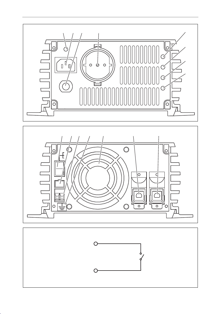
Front view (fig. 1, page 3)
The version for continental Europe is pictured.
No. Description
1 Grid: This LED lights up if the inverter is supplied with external 230 V mains
power; the priority circuit is active.
2 Connection for the external 230 V power supply
3 Circuit breaker: Fuse
4 230 Vw output
5 POWER: This LED lights up when the inverter is switched on.
6 OLP: This LED lights up when the consumers connected draw too much
electricity.
7 UVP: This LED lights up when battery capacity is too weak.
8 OVP: This LED lights up when the input voltage is too high.
11

EN
Fastening and connecting the inverter PerfectPower
Rear view (fig. 2, page 3)
No. Description
1 Main switch
2 Connection for MCR9 remote control
3 Connection for an external switch contact
4 Earth connection
5Fan
6 Negative terminal
7 Positive terminal
8 Fastening and connecting the inverter
8.1 Fastening the inverter
WARNING!
!
• Ensure the device is standing firmly.
Set up the device securely and fasten it in such a way that
– it cannot tip over or fall down
– it cannot move while the vehicle is in motion
• Take precautions necessary to ensure that it is out of reach of
children. Dangerous situations may occur which cannot be
recognised by children!
You can fasten the inverter using the holders supplied.
When selecting the installation location, observe the following instructions:
• Do not operate the device
– in wet or damp environments
– in dusty environments
– in the vicinity of flammable materials
– in spaces where there is a danger of explosion
• Do not expose the device to a heat source (such as direct sunlight or heating).
Avoid additional heating of the device in this way.
• Make sure the cables are the correct length and choose the installation location
near the battery supply.
12

EN
PerfectPower Fastening and connecting the inverter
• Select a well-ventilated location for the device.
A ventilation system must be present for installations in small, enclosed spaces.
• Make sure that the air intake on the front of the inverter remains clear.
• Select a mounting surface which is flat and sufficiently firm.
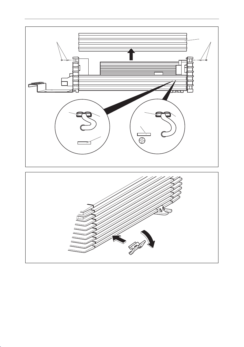
Fasten the inverter as follows (fig. 5, page 4):
NOTICE!
A
➤ Clip two holders on the left bar and two on the lower right bar.
You can move the holders as required.
➤ Fasten the inverter by screwing one screw through each hole in the holder.
8.2 Connecting the inverter
!
Before drilling any holes, make sure that no electrical cables or other
parts of the vehicle can be damaged by drilling, sawing and filing.
WARNING!
The inverter may only be connected by a qualified workshop.
The following information is intended for specialists who are familiar with
the guidelines and safety precautions to be applied.
Observe the following safety instructions for the electrical connections:
NOTICE!
A
• Caution – Risk of short circuit!
When working on the vehicle, always disconnect the earth
connection to the supply battery.
• Disconnect the 230 V external power supply to the caravan.
• If you have to feed cables through metal walls or other walls with
sharp edges, use ducts or tubes to prevent damage.
• Do not lay cables which are loose or bent next to electrically
conductive material (metal).
• Fasten the cables securely.
• Do not pull on the cables.
• Do not lay the 230 V mains cable and the 12/24 V DC cable in the
same duct.
• Lay the cables so that they cannot be tripped over or damaged.
13

EN
Fastening and connecting the inverter PerfectPower
WARNING! Danger of electrocution!
!
Earthing the inverter
➤ Connect the earth connection on the inverter (fig. 2 4, page 3) with the earth of
the vehicle.
Connecting the inverter to the battery
I
A
➤ Connect the terminal on the red battery connection cable to the positive terminal
(fig. 2 7, page 3) on the inverter.
If you wish to connect more than one consumer to the inverter and install
a socket distributor loop, you must arrange a circuit breaker (residual
current circuit breaker) and set a grounding bridge in the inverter, see
chapter “Connecting multiple consumers” on page 15.
NOTE
Please be aware that all volatile memories of the connected electric consumers will lose their stored data if the battery is disconnected.
NOTICE!
Make sure the polarity is correct. If the positive and negative
connections are reversed, this may damage the device.
➤ Connect the terminal on the black battery connection cable to the negative
terminal (fig. 2 6, page 3) on the inverter.
➤ Check the connections are secure.
You might have to tighten the screws again later.
NOTE
I
➤ Connect the red battery connection cable to the positive terminal on the battery.
➤ Connect the black battery connection cable to the negative terminal on the
battery.
14
Sparks may be produced when the connections are made due to the
internal capacitors being charged.

EN
PerfectPower Fastening and connecting the inverter
Connecting the inverter to the 230 V mains supply
➤ Plug the 230 V connection cable into the connector for the 230 V power supply
to the inverter (fig. 1 2, page 3).
➤ Connect the 230 V connection cable to a 230 V socket in the vehicle.
Connecting the remote control to the inverter
➤ Switch off the inverter.
➤ Insert the cable end of the remote control into the connection (fig. 2 2,
page 3).
➤ Set the main switch (fig. 2 1, page 3) to “Remote”.
Connecting the external switch contact to the inverter
➤ Switch off the inverter.
➤ Connect the external switch contact (power supply from the inverter) at the
remote port (fig. 2 3, page 3) in accordance with the wiring diagram (fig. 3,
page 3),
➤ Set the main switch (fig. 2 1, page 3) to “Remote”.
NOTE
I
If you wish to use an external switch contact with a power supply of it
own, e.g. the ignition, you must interconnect a suitable relay.
8.3 Connecting multiple consumers
WARNING! Danger of electrocution!
!
The device is equipped at delivery with galvanic isolation. For the safe operation of
multiple consumers, it is essential that a circuit breaker (residual current circuit
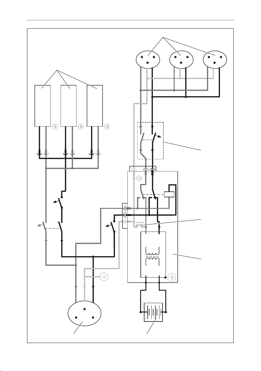
breaker) is built into the socket distribution circuit, see sample circuit diagram in
fig. 6, page 5.
If you wish to connect more than one consumer to the inverter and install
a socket distribution circuit, you must arrange a circuit breaker (residual
current circuit breaker) and set a grounding bridge in the inverter. The
grounding bridge may only be connected by a trained professional who
is familiar with the relevant VDE (German Engineering Society) regulations.
15

EN
Fastening and connecting the inverter PerfectPower
Sample circuit diagram legend:
No. in fig. 6,
page 5
1 230 Vw power source
2 Additional devices, e.g. battery charger, refrigerator
3 DC power source (battery)
4Inverter
5 Grounding bridge set
6 Circuit breaker (residual current circuit breaker)
7 Socket distribution circuit for consumers
➤ Install a residual current circuit breaker in the socket distribution circuit.
Setting grounding bridge (fig. 4, page 4)
WARNING! Danger of electrocution!
!
I
The grounding bridge may only be connected by a trained professional
who is familiar with the relevant VDE (German Engineering Society)
regulations.
NOTE
The grounding bridge plug is always plugged into socket “FG”
(insulated AC current) when delivered.
Explanation
(At delivery: not set, shown by dotted line)
➤ Unscrew the top four fastening screws (2) on the front of the device with a hex
key.
➤ Take off the cover (1).
NOTICE!
A
➤ Remove the plug (3) from socket “FG” (4).
➤ Insert the plug (3) into socket “N + FG” (5).
➤ Replace the device cover (1) and fix using the screws (2).
The grounding bridge is changed with sockets “FG” and “N + FG”. Do
not alter the other sockets, otherwise the device may be damaged.
16

EN
PerfectPower Using the inverter
9Using the inverter
NOTICE!
A
A
When using the inverter, observe the following instructions:
• If the battery voltage drops below the alarm value during operation (see “Low
voltage alarm” in chapter “Technical data” on page 21), a warning signal sounds
and LED “UVP” (fig. 1 7, page 3) lights up.
• If the battery voltage drops below the shutdown value (See “Low voltage
shutdown” in chapter “Technical data” on page 21), the inverter switches off.
• If the inverter overheats, it switches off and LED “OLP” (fig. 1 6, page 3) lights
up.
After it cools down, the inverter automatically switches back on.
• When operating the inverter at a high load for lengthy periods, it is advisable to
start the engine in order to recharge the vehicle battery.
If no circuit breaker is present: If the inverter is connected to the
external mains voltage, the 230 V output socket is earthed.
If there is no external mains voltage, the inverter is only connected to the
battery (DC operation). In this case, the 230 V output socket is not
earthed, but safeguarded with the protective insulation instead.
NOTICE! Risk of short circuit!
You must switch on the inverter first before switching on the consumers.
➤ Connect your consumer to the 230 V output (fig. 1 4, page 3).
You can also connect a socket distribution system.
9.1 Using the inverter without remote control
➤ Set the main switch (fig. 2 1, page 3) to
– “ON” to switch the inverter on
– “OFF” to switch the inverter off
✓ LED “POWER” lights up when the inverter is switched on.
17

EN
Cleaning and caring for the inverter PerfectPower
9.2 Using the inverter with a remote control
NOTE
I
➤ Set the main switch (fig. 2 1, page 3) to “Remote”.
➤ Switch the inverter on or off using
– the buttons on the remote control or
– the external switch contact
✓ LED “POWER” lights up when the inverter is switched on.
Refer to the operating instructions of the remote control which are also
included in the scope of delivery.
10 Cleaning and caring for the inverter
NOTICE!
A
➤ Occasionally clean the product with a damp cloth.
Do not use sharp or hard objects or cleaning agents for cleaning as these
may damage the product.
18

EN
PerfectPower Rectifying faults
11 Rectifying faults
Fault Cause Remedy
No output voltage No contact to the battery Check contact and cable.
Switch on the ignition if
necessary.
Overheating Switch off the consumer.
Let the inverter cool down
and ensure better ventilation.
If necessary, reduce the
constant load.
Input voltage too high Check the input voltage on
the inverter and compare
with the technical data for the
inverter.
The device switches on and
off repeatedly
The inverter switches off
when the consumers are
switched on
The output voltage is too
low
Defective fuse (in the inverter
or the vehicle)
Defective device Replace the device.
Excessive constant load Reduce the load.
Starting current too high Compare consumer power
Battery voltage is lower than
shutdown value (see “Low
voltage shutdown” in chapter
“Technical data” on page 21)
Replace the fuse with one of
the same specifications.
with the maximum power
from the inverter.
Charge the battery (start the
engine).
I
NOTE
The output voltage can only be measured correctly with a True-RMS
measuring device.
19

EN
Guarantee PerfectPower
12 Guarantee
The statutory warranty period applies. If the product is defective, please contact the
manufacturer's branch in your country (see the back of the instruction manual for the
addresses) or your retailer.
For repair and guarantee processing, please include the following documents when
you send in the device:
• A copy of the receipt with purchasing date
• A reason for the claim or description of the fault
13 Disposal
➤ Place the packaging material in the appropriate recycling waste bins wherever
possible.
If you wish to finally dispose of the product, ask your local recycling centre
or specialist dealer for details about how to do this in accordance with the
M
applicable disposal regulations.
20

EN
PerfectPower Technical data
26
14 Technical data
NOTE
I
The following technical data applies to all inverters:
The constant output in the technical data may be reduced for ambient
temperatures of more than 40 °C (e.g. in engine or heating
compartments or direct sunlight).
PP1002
PP2002
Output voltage:
Output frequency: 50 Hz ± 2 Hz
Idle current consumption: < 1.5 A < 1.5 A
Efficiency at constant load: > 85 %
Input voltage range: 11 – 15 Vg 22 – 30 Vg
Mains input voltage: 230 Vw
Low voltage alarm: 11 V 22 V
Low voltage shutdown: 10.5 V 21 V
Low voltage restart: 12.2 V 24.4 V
Excess voltage shutdown: 15.5 V 30.5 V
Overload shutdown: 130 %
Excess temperature shutdown: 80 °C
Priority circuit fuse: 10 A
Ambient temperature
– storage:
– operation:
230 V
–30 °C – +70 °C
0°C – +40°C
PP1004
PP2004
Humidity
– storage:
– operation:
Testing/certification:
20 % – 90 %
10 % – 95 %
21

EN
Technical data PerfectPower
PP1002 PP1004
Constant output power: 1000 W
Peak output power: 2000 W
DC fuse: 30 A x 4 15 A x 4
Dimensions W x L x H: 176 x 338 x 95 mm
Weight: 3.5 kg
PP2002 PP2004
Constant output power: 2000 W
Peak output power: 4000 W
DC fuse: 30 A x 8 15 A x 8
Dimensions W x L x H: 176 x 443 x 95 mm
Weight: 5 kg
22

DE
PerfectPower
Bitte lesen Sie diese Anleitung vor Einbau und Inbetriebnahme sorgfältig
durch und bewahren Sie sie auf. Geben Sie sie im Falle einer Weitergabe
des Produktes an den Nutzer weiter.
Inhaltsverzeichnis
1 Erklärung der Symbole . . . . . . . . . . . . . . . . . . . . . . . . . . . . . . . . . . . . . . . . . 24
2 Allgemeine Sicherheitshinweise . . . . . . . . . . . . . . . . . . . . . . . . . . . . . . . . . 24
3 Lieferumfang . . . . . . . . . . . . . . . . . . . . . . . . . . . . . . . . . . . . . . . . . . . . . . . . . 26
4 Zubehör. . . . . . . . . . . . . . . . . . . . . . . . . . . . . . . . . . . . . . . . . . . . . . . . . . . . . 26
5 Zielgruppe dieser Anleitung . . . . . . . . . . . . . . . . . . . . . . . . . . . . . . . . . . . . 26
6 Bestimmungsgemäßer Gebrauch . . . . . . . . . . . . . . . . . . . . . . . . . . . . . . . . 27
7 Technische Beschreibung . . . . . . . . . . . . . . . . . . . . . . . . . . . . . . . . . . . . . . 27
8 Wechselrichter befestigen und anschließen . . . . . . . . . . . . . . . . . . . . . . . . 30
9 Wechselrichter benutzen . . . . . . . . . . . . . . . . . . . . . . . . . . . . . . . . . . . . . . . 35
10 Wechselrichter pflegen und reinigen . . . . . . . . . . . . . . . . . . . . . . . . . . . . . 36
11 Fehlerbeseitigung. . . . . . . . . . . . . . . . . . . . . . . . . . . . . . . . . . . . . . . . . . . . . 37
12 Gewährleistung. . . . . . . . . . . . . . . . . . . . . . . . . . . . . . . . . . . . . . . . . . . . . . . 38
13 Entsorgung . . . . . . . . . . . . . . . . . . . . . . . . . . . . . . . . . . . . . . . . . . . . . . . . . . 38
14 Technische Daten . . . . . . . . . . . . . . . . . . . . . . . . . . . . . . . . . . . . . . . . . . . . . 39
23

DE
Erklärung der Symbole PerfectPower
1 Erklärung der Symbole
WARNUNG!
!
A
I
Sicherheitshinweis: Nichtbeachtung kann zu Tod oder schwerer
Verletzung führen.
ACHTUNG!
Nichtbeachtung kann zu Materialschäden führen und die Funktion des
Produktes beeinträchtigen.
HINWEIS
Ergänzende Informationen zur Bedienung des Produktes.
2 Allgemeine Sicherheitshinweise
Der Hersteller übernimmt in folgenden Fällen keine Haftung für Schäden:
• Montage- oder Anschlussfehler
• Beschädigungen am Produkt durch mechanische Einflüsse und Über-
spannungen
• Veränderungen am Produkt ohne ausdrückliche Genehmigung vom Hersteller
• Verwendung für andere als die in der Anleitung beschriebenen Zwecke
2.1 Allgemeine Sicherheit
WARNUNG!
!
24
• Benutzen Sie das Gerät nur zu seinem bestimmungsgemäßen
Gebrauch.
• Die Wartung und Reparatur darf nur durch eine Fachkraft geschehen,
die mit den damit verbundenen Gefahren bzw. einschlägigen Vorschriften vertraut ist.
• Personen (einschließlich Kinder), die aufgrund ihrer physischen,
sensorischen oder geistigen Fähigkeiten oder ihrer Unerfahrenheit
oder Unkenntnis nicht in der Lage sind, das Produkt sicher zu
benutzen, sollten dieses Produkt nicht ohne Aufsicht oder Anweisung
durch eine verantwortliche Person nutzen.

DE
PerfectPower Allgemeine Sicherheitshinweise
• Elektrogeräte sind kein Kinderspielzeug!
Verwahren und benutzen Sie das Gerät außerhalb der Reichweite von
Kindern.
2.2 Sicherheit bei der Installation des Gerätes
WARNUNG!
!
• Die Installation des Gerätes darf ausschließlich von entsprechend aus-
gebildeten Fachbetrieben durchgeführt werden, die mit den anzuwendenen Richtlinien und Sicherheitsvorkehrungen vertraut sind.
• Bei falscher Installation elektrischer Geräte auf Booten kann es zu
Korrosionsschäden am Boot kommen. Die Installation des Gerätes
sollte von einem fachkundigen (Boots-)Elektriker durchgeführt
werden.
2.3 Sicherheit beim Betrieb des Gerätes
WARNUNG!
!
Beachten Sie folgende grundsätzliche Sicherheitsmaßnahmen beim
Gebrauch von elektrischen Geräten zum Schutz vor:
• elektrischem Schlag
• Brandgefahr
• Verletzungen
• Betreiben Sie das Gerät nur, wenn das Gehäuse und die Leitungen
unbeschädigt sind.
• Achten Sie darauf, dass Luftein- und Ausgänge des Geräts nicht verdeckt werden.
• Achten Sie auf gute Belüftung. Der Wechselrichter produziert Verlustwärme, die abgeführt werden muss.
• Unterbrechen Sie bei Arbeiten am Gerät immer die Stromversorgung.
25

DE
Lieferumfang PerfectPower
3 Lieferumfang
Menge Bezeichnung
1 Wechselrichter
1 230-V-Anschlusskabel
4 Montagehalterungen
1 Montageblech
2 Kabelschuhe
1 Bedienungsanleitung
4Zubehör
Als Zubehör erhältlich (nicht im Lieferumfang enthalten):
Bezeichnung Art.-Nr
Fernbedienung MCR9 9600000091
Bei Fragen zu Zubehör wenden Sie sich bitte an Ihren Service-Partner.
5 Zielgruppe dieser Anleitung
Das Kapitel „Wechselrichter anschließen“ auf Seite 31 wendet sich ausschließlich an
Fachleute, die mit den entsprechenden VDE-Richtlinien vertraut sind.
Alle übrigen Kapitel wenden sich auch an die Benutzer des Gerätes.
26

DE
PerfectPower Bestimmungsgemäßer Gebrauch
6 Bestimmungsgemäßer Gebrauch
WARNUNG!
!
Die Wechselrichter PP1002, PP1004, PP2002 und PP2004 dienen zur Spannungsversorgung von 230-V-Verbrauchern an einer 12-V- oder 24-V-Spannungsversorgung:
• 12 V: PP1002 und PP2002
• 24 V: PP1004 und PP2004
Die Wechselrichter sind geeignet für die Nutzung in Reisemobilen, Nutzfahrzeugen
sowie Motor- und Segelyachten.
Der Wechselrichter darf nicht in Fahrzeugen eingesetzt werden, bei
denen der Plus-Pol der Batterie mit dem Chassis verbunden ist.
7 Technische Beschreibung
Die Wechselrichter PP1000 und PP2000 bestehen aus zwei Funktionseinheiten:
• Wechselrichter-Schaltung: generiert eine 230-V-Wechselspannung aus einer
Batteriespannung von
– 12 V: PP1002 und PP2002
– 24 V: PP1004 und PP2004
• Netz-Vorrangschaltung: schaltet automatisch zwischen 230-V-FremdNetzspannung (z. B. vom Campingplatz) und aus einer Batterie generierten
230-V-Spannung um
Vorrang hat die Fremd-Netzspannung: Nur wenn keine externe Spannung mehr
vorhanden ist, wird die Ausgangssteckdose vom externen Spannungskreis
getrennt und mit dem Spannungskreis des Wechselrichters verbunden. So ist
sichergestellt, dass immer eine 230-V-Spannung an der Ausgangssteckdose
anliegt.
Vom Inverterbetrieb zur Landstromversorgung:
Die Umschaltung vom Inverterbetrieb, bei dem die 230-V-Wechselspannung
aus der Batteriespannung erzeugt wird, zur Landstromversorgung erfolgt
verzögert.
Mit Einstecken des Steckers in die Außensteckdose (Campingplatz, Hafen) wird
nach einer Verzögerungszeits von ca. 4 s der Inverter ausgeschaltet. Nach
weiteren 2 s wird der Landstrom durchgeschaltet. Hierdurch wird den angeschlossenen Geräten Zeit zum sauberen Abschalten gegeben.
27

DE
Technische Beschreibung PerfectPower
Vom Landstrom zum Inverterbetrieb:
Die Umschaltung vom Landstrom zum Inverterbetrieb ist ebenso mit einer
Verzögerung behaftet.
Fällt der Landstrom aus, schaltet sich der Inverter nach 2 Sekunden ein.
ACHTUNG!
A
Der Wechselrichter ist mit einem thermischen und einem elektrischen Überlastungsschutz sowie einem Unter- und Überspannungsschutz ausgestattet. Der Wechselrichter schaltet ab:
• wenn die interne Temperatur des Wechselrichters zu hoch ist
• wenn die Belastung die Leistungswerte übersteigt, die in den Technischen Daten
genannt sind
• wenn die Eingangsspannung zu niedrig oder zu hoch ist
An den Wechselrichter kann ein einzelner Verbraucher angeschlossen werden oder
ein Steckdosen-Verteilersystem, um ein 230-V-Bordnetz mit mehreren Steckdosen
zu realisieren.
Angeschlossene Geräte sollten beim Umschalten ausgeschaltet sein.
Da sie für 2 s keine Spannung bekommen, müssen sie eventuell wieder
eingeschaltet werden.
Das Gerät ist im Lieferzustand mit galvanischer Trennung ausgestattet. Zum sicheren
Betrieb von mehreren Verbrauchern ist es zwingend notwendig, dass im
Steckdosenverteilerkreis ein Schutzschalter (FI-Schalter) eingebaut und die Erdungsbrücke im Wechselrichter gesetzt wird.
HINWEIS
I
Der Wechselrichter kann manuell oder mit einer Fernbedienung eingeschaltet
werden.
Die Kühlung erfolgt über einen lastabhängig gesteuerten Lüfter.
Beachten Sie beim Anschluss von Geräten mit elektrischem Antrieb
(z. B. Bohrmaschine, Kühlschrank usw.), dass diese zum Anlaufen oft
eine höhere Leistung benötigen als auf dem Typen-schild angegeben.
28

DE
PerfectPower Technische Beschreibung
7.1 Bedienelemente
HINWEIS
I
Vorderansicht (Abb. 1, Seite 3)
Abgebildet ist die Version für Kontinentaleuropa.
Nr. Beschreibung
1 Grid: Diese LED leuchtet, wenn der Wechselrichter von einer externen
230-V-Netzspannung versorgt wird; die Vorrangschaltung ist aktiv.
2 Anschluss für die externe 230-V-Spannungsversorgung
3 Circuit Breaker: Sicherung
4 230-Vw-Ausgang
5 POWER: Diese LED leuchtet, wenn der Wechselrichter eingeschaltet ist.
6 OLP: Diese LED leuchtet, wenn die angeschlossenen Verbraucher zu viel
Strom aufnehmen.
7 UVP: Diese LED leuchtet, wenn die Batteriekapazität zu schwach ist.
8 OVP: Diese LED leuchtet, wenn die Eingangsspannung zu hoch ist.
Rückansicht (Abb. 2, Seite 3)
Nr. Beschreibung
1 Hauptschalter
2 Anschluss Fernbedienung MCR9
3
4 Masseanschluss
5Lüfter
6Minusklemme
7 Plusklemme
Anschluss für e
xternen Schaltkontakt
29

DE
Wechselrichter befestigen und anschließen PerfectPower
8 Wechselrichter befestigen und
anschließen
8.1 Wechselrichter befestigen
WARNUNG!
!
Sie können den Wechselrichter mit den beiliegenden Halterungen befestigen.
Beachten Sie folgende Hinweise bei der Wahl des Montageortes:
• Betreiben Sie das Gerät nicht in
– feuchter oder nasser Umgebung
–staubiger Umgebung
– Umgebungen mit entflammbaren Materialien
– explosionsgefährdeten Räumen
• Setzen Sie das Gerät keiner Wärmequelle (Sonneneinstrahlung, Heizung usw.)
aus. Vermeiden Sie so zusätzliche Erwärmung des Gerätes.
• Beachten Sie die Kabellängen und wählen Sie einen Montageort nahe der
Versorgungsbatterie.
• Wählen Sie einen gut belüfteten Montageort.
Bei Installationen in geschlossenen kleinen Räumen sollte eine Be- und
Entlüftung vorhanden sein.
• Achten Sie darauf, dass der Lufteintritt an den Stirnseiten des Wechselrichters
freibleibt.
• Wählen Sie eine Montagefläche, die eben ist und eine ausreichende Festigkeit
aufweist.
• Achten Sie auf einen sicheren Stand!
Stellen Sie das Gerät sicher auf und befestigen Sie es so, dass
– es nicht umstürzen oder herabfallen kann
– ein Bewegen während der Fahrt nicht möglich ist
• Sichern Sie das Gerät so, dass Kinder keinen Zugriff darauf haben. Es
können Gefahren entstehen, die von Kindern nicht erkannt werden.
30
 Loading...