

Dometic Group MSI2312T, MSI2324T, MSI3512T, MSI3524T Installation and Operating Manual [ml]
ENDEFR
ES
PTITNLDASVNOFIRUPLSKCS
HU
ENERGY & LIGHTING
SINEPOWER
ENB
ENB
S1
S2
JUMP
S3
RESET
S4
S5
LCM CAN1 CAN2
S6
S7
S8
NEG -
1 2
POS +
MSI2312T, MSI2324T,
MSI3512T, MSI3524T
Sine wave inverter
Installation and Operating Manual. . . . . . . . 9
Sinus-Wechselrichter
Montage- und Bedienungsanleitung. . . . . 31
Onduleur sinusoïdal
Instructions de montage
et de service . . . . . . . . . . . . . . . . . . . . . . . . .54
Convertidor de ondas seno
Instrucciones de montaje y de uso. . . . . . .77
Conversor sinusoidal
Instruções de montagem e manual de
instruções . . . . . . . . . . . . . . . . . . . . . . . . . .100
Inverter sinusoidale
Istruzioni di montaggio e d’uso . . . . . . . .123
Sinus ondulator
Montagehandleiding en
gebruiksaanwijzing . . . . . . . . . . . . . . . . . .146
Sinus ensretter
Monterings- og betjeningsvejledning. . . 170
Sinus växelriktare
Monterings- och bruksanvisning. . . . . . . 192
Sinus vekselretter
Monterings- og bruksanvisning. . . . . . . . 214
Sinus -vaihtosuuntaaja
Asennus- ja käyttöohje . . . . . . . . . . . . . . . 236
Синусоидальный инвертор
Инструкция по монтажу и эксплуатации 258
Przetwornica sinusoidalna
Instrukcja montażu i obsługi. . . . . . . . . . .283
Sínusový menič napätia
Návod na montáž a uvedenie
do prevádzky. . . . . . . . . . . . . . . . . . . . . . .306
Sinusový měnič
Návod k montáži a obsluze . . . . . . . . . . .328
Szinuszos inverter
Szerelési és használati útmutató . . . . . . .350

SinePower
NEG -
LCM
CAN1
CAN2
RESET
S1
S2
S
3
S4
S5
S
6
S7
S8
EN
B
ENB
JU
MP
1 2
POS +
1
3
2
1
NEG -
LCM
CAN1
CAN2
RESET
S1
S2
S3
S4
S5
S
6
S7
S8
ENB
ENB
JUMP
1 2
POS +
25 cm
25 cm
2
3
SinePower
3
1
2
3
4
4
AC OUTPUT
AC
INPUT
AC
OUTPUT
CAN1
BREAKER
NEG -
LCM CAN2
RESET
ON OFF
S1
S2
S3
S4
S5
S6
S7
S8
GND
ENB
ENB
JUMP
1 2
POS +
3
2
9
4
1
5
7
81013
14
1112
6
5
AB
EN
B
ENB
S1
S2
JUM
S3
P
RESET
S4
S5
LCM
S6
S7
CAN1
S8
NEG -
1 2
CAN2
POS +
ENB
ENB
S1
S2
JUMP
S3
RESET
S4
S5
LCM
S6
S7
CAN1
S8
NEG -
1 2
CAN2
POS +
4
SinePower
Input
230 Vw
Output
230 Vw
N
MSI
DC
Input
DC
230 Vw
FI 2
RCD
FI 1
RCD
PE
L1
N
PE
L1
N
PE
L1
N
PE
L1
7
2
654
1
3
6
5
SinePower
AC
INPUT
AC INPUT / N
AC INPUT / L
AC
OUTPUT
AC OUTPUT / N
AC OUTPUT / L
GND
GND
gr/ge
bk
wt
br
bl
LLNN
7
8
9
0
a
ENB
GND
ENB
ON:INV.
OFF:INV.
BAT+
BAT–
ON:INV.
OFF:INV.
ON
OFF
ON
OFF
ENB
GND
TR
ON:INV.
OFF:INV.
ENB
GND
HI:INV.
LOW:INV.
ON
OFF
+
DC POWER
–
ON
(TR ON)
OFF
(TR OFF)
6
AC OUTPUT
AC
INPUT
AC
OUTPUT
AC OUTPUT
AC
INPUT
AC
OUTPUT
AC OUTPUT
AC
INPUT
AC
OUTPUT
CAN1 CAN2
CAN2
NEG(–) POS(+)
NEG(–) POS(+)
NEG(–) POS(+)
CAN1
rtsw
rtsw rtsw
A
BC
rt
rt
1
1
b
SinePower
7
AC OUTPUT
AC
INPUT
AC
OUTPUT
CAN1
BREAKER
NEG -
LCM CAN2
RESET
ON OFF
S1
S2
S3
S4
S5
S6
S7
S8
GND
ENB
ENB
JUMP
1 2
POS +
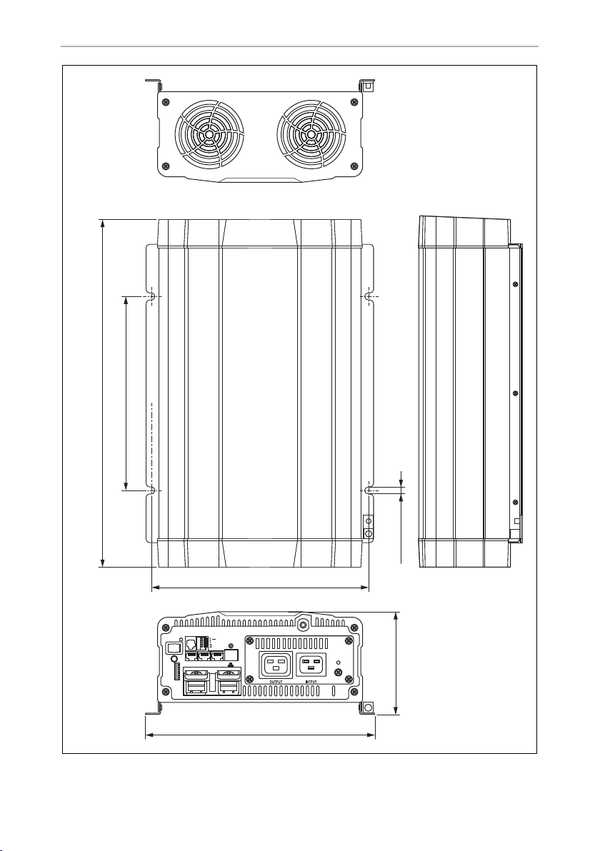
268,6 mm
Ø8,5 mm
283 mm
MSI2300: 436 mm
MSI3500: 496 mm
240 mm
128,4 mm
c
SinePower
8

EN
SinePower
Please read this instruction manual carefully before installation and first
use, and store it in a safe place. If you pass on the product to another
person, hand over this instruction manual along with it.
Table of contents
1 Explanation of symbols . . . . . . . . . . . . . . . . . . . . . . . . . . . . . . . . . . . . . . . . . .10
2 General safety instructions . . . . . . . . . . . . . . . . . . . . . . . . . . . . . . . . . . . . . . .10
3 Scope of delivery . . . . . . . . . . . . . . . . . . . . . . . . . . . . . . . . . . . . . . . . . . . . . .12
4 Accessories . . . . . . . . . . . . . . . . . . . . . . . . . . . . . . . . . . . . . . . . . . . . . . . . . . .12
5 Target group for this manual. . . . . . . . . . . . . . . . . . . . . . . . . . . . . . . . . . . . . .12
6 Intended use . . . . . . . . . . . . . . . . . . . . . . . . . . . . . . . . . . . . . . . . . . . . . . . . . .13
7 Technical description . . . . . . . . . . . . . . . . . . . . . . . . . . . . . . . . . . . . . . . . . . . 13
8 Fitting the inverter . . . . . . . . . . . . . . . . . . . . . . . . . . . . . . . . . . . . . . . . . . . . . .16
9 Connecting the inverter . . . . . . . . . . . . . . . . . . . . . . . . . . . . . . . . . . . . . . . . . 17
10 Using the inverter . . . . . . . . . . . . . . . . . . . . . . . . . . . . . . . . . . . . . . . . . . . . . 23
11 Cleaning and caring for the inverter. . . . . . . . . . . . . . . . . . . . . . . . . . . . . . . 26
12 Troubleshooting . . . . . . . . . . . . . . . . . . . . . . . . . . . . . . . . . . . . . . . . . . . . . . 27
13 Warranty . . . . . . . . . . . . . . . . . . . . . . . . . . . . . . . . . . . . . . . . . . . . . . . . . . . . 28
14 Disposal . . . . . . . . . . . . . . . . . . . . . . . . . . . . . . . . . . . . . . . . . . . . . . . . . . . . . 28
15 Technical data . . . . . . . . . . . . . . . . . . . . . . . . . . . . . . . . . . . . . . . . . . . . . . . . 29
9

EN
Explanation of symbols SinePower
1 Explanation of symbols
WARNING!
!
A
I
Safety instruction: Failure to observe this instruction can cause fatal or
serious injury.
NOTICE!
Failure to observe this instruction can cause material damage and impair
the function of the product.
NOTE
Supplementary information for operating the product.
2 General safety instructions
2.1 General safety
The manufacturer accepts no liability for damage in the following cases:
• Faulty assembly or connection
• Damage to the product resulting from mechanical influences and excess voltage
• Alterations to the product without express permission from the manufacturer
• Use for purposes other than those described in the operating manual
!
10
WARNING!
• Only use the device as intended.
• Do not operate the device in a damp or wet environment.
• Do not operate the device near any flammable materials.
• Do not operate the device in areas that are potentially explosive.
• Maintenance and repair work may only be carried out by qualified per-
sonnel who are familiar with the risks involved and the relevant regulations.
• People (including children) whose physical, sensory or mental capacities or whose lack of experience or knowledge prevent them from
using this product safely should not use it without the supervision or
instruction of a responsible person.

EN
SinePower General safety instructions
• Electrical devices are not toys
Always keep and use the device out of the reach of children.
2.2 Safety when installing the device
WARNING!
!
A
• Installing the device may only be performed by qualified personnel
who are familiar with the guidelines and safety precautions to be
applied.
• If electrical devices are incorrectly installed on boats, corrosion damage might occur. The device should be installed by a specialist
(marine) electrician.
NOTICE!
• Ensure that the device is standing firmly.
The device must be set up and fastened in such a way that it cannot tip
over or fall down.
• Do not expose the device to a heat source (such as direct sunlight or
heating). Avoid additional heating of the device in this way.
• If cables have to be fed through metal walls or other walls with sharp
edges, use ducts or tubes to prevent damage.
• Do not lay cables which are loose or bent next to electrically conductive material (metal).
• Do not pull on the cables.
• Do not lay the 230 V mains cable and the 12/24 V DC cable in the
same duct.
• Fasten the cables securely.
• Lay the cables so that they cannot be tripped over or damaged.
2.3 Operating the device safely
WARNING!
!
• Operate the device only if you are certain that the housing and the
cables are undamaged.
• Even after the fuse triggers, parts of the inverter remain live.
• Always disconnect the power supply when working on the device.
11

EN
Scope of delivery SinePower
NOTICE!
A
• Make sure the air inlets and outlets of the device are not covered.
• Ensure good ventilation. The inverter produces dissipated heat which
has to be diverted.
• Do not connect the 230 V output of the inverter (fig. 5 7, page 4) to
a different 230 V source.
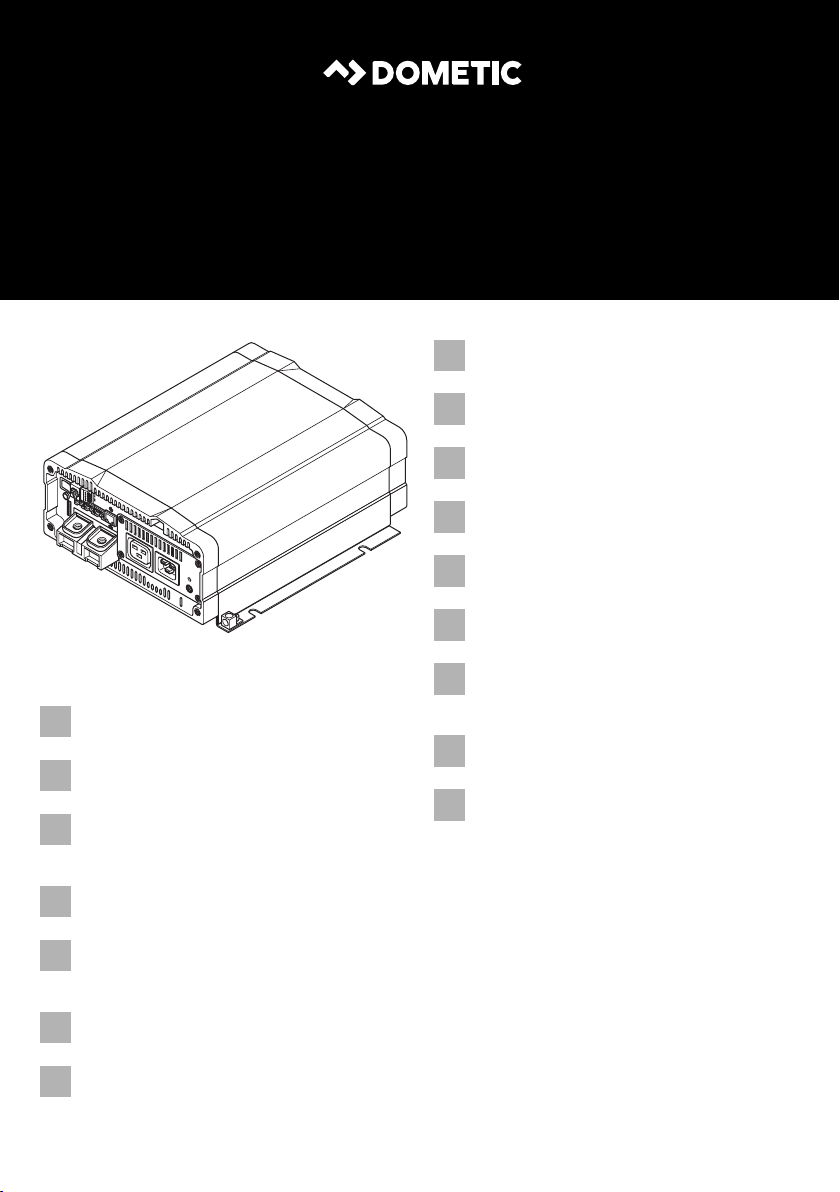
3Scope of delivery
No. in
fig. 1,
page 3
Designation
1 Sine wave inverter
2 Connection cable with safety coupling
(for 230 Vw output)
3 Connection cable with safety plug
(for 230 Vw supply)
– Operating manual
4Accessories
Designation Ref. no.
Remote control MCR7 9600000090
Remote control MCR9 9600000091
5 Target group for this manual
The electrical installation (chapter “Connecting the inverter” on page 17) is intended
for professionals who are familiar with the applicable regulations of the country in
which the equipment is to be installed and/or used.
All other chapters are intended for the users.
12

EN
SinePower Intended use
6 Intended use
WARNING!
!
The wave inverter converts direct current of
• 12 Vg (MSI2312T, MSI3512T)
• 24 Vg (MSI 2324T, MSI3524T)
into a 200 – 240 V AC supply of 50 Hz or 60 Hz.
Never use the inverter on vehicles where the positive terminal of the
battery is connected to the chassis.
7 Technical description
The inverters can be operated wherever
• a 12 Vg connection (MSI2312T, MSI3512T)
• a 24 Vg connection (MSI2324T, MSI3524T)
is available. The light-weight and compact construction of this device allows for easy
installation in mobile homes, commercial vehicles or motor and sailing yachts.
The output voltage corresponds to the household voltage from the socket (pure sine
wave, THD < 3%).
Please observe the values for constant output power and peak output power as indicated in chapter “Technical data” on page 29 . Never connect devices that have a
higher power requirement.
NOTE
I
The inverter has various protective mechanisms.
• Overvoltage shutdown: The inverter shuts itself off when the voltage exceeds
the cut-off value. It restarts when the voltage returns to the restart value.
• Undervoltage shutdown: The inverter shuts itself off when the voltage sinks
below the cut-off value. It restarts when the voltage rises to the restart value.
• Excess temperature shutdown: The inverter switches off when the tempera-
ture inside the device or the temperature on the cooling element exceeds a cutoff value. It restarts when the voltage rises to the restart value.
Note when connecting devices with an electrical drive (such as power
drills and refrigerators), that they often require more power than is
indicated on the type plate.
13

EN
Technical description SinePower
• Overloading and short circuit shutdown: The LED on the inverter indicates
an op era ting faul t (co nsta nt re d lig ht) wh en a n e xce ss loa d is c onne cted or a s hort
circuit has occurred. The fuse in the device must be pressed in again by hand after
it is triggered by excess current.
• Incorrect polarity protection: The incorrect polarity protection prevents the
wrong polarity when connecting the inverter.
NOTE
I
The inverters have a 230 Vw socket and a connection terminal for permanent
connection.
Due to the voltage synchronisation with the AC input voltage, the inverter is suitable
for operating sensitive consumers which react to an irregular voltage supply.
The device can also be configured with a PC via an RS-232 interface and using the
DIP switches on the device.
The inverter can be switched to an energy-saving mode to prevent the connected
battery from discharging too quickly.
Parallel operation allows up to three inverters (of the same model) to run at the same
time.
The individual values are found in the chapter “Technical data” on
page 29.
The inverter can be easily controlled using the remote control (accessory).
14

EN
SinePower Technical description
7.1 Control elements
Control elements of the inverter (fig. 5, page 4)
Item Description Description
1 Dip switch Makes settings on the inverter (such as mains
voltage, mains frequency, energy-saving
mode).
2 LED See chapter “Status indications” on page 23
3 Main switch
“ON/OFF/REMOTE” switch
4 Fuse Protects the inverter from overload.
5 Grounding screw Sets or removes the grounding bridge
Switches the device on, off or to operation via
the remote control (accessory)
The fuse can be pressed in again once it has
triggered.
7.2 Connections
NOTE
I
Connections of the inverter (fig. 5, page 4)
The version for continental Europe is depicted.
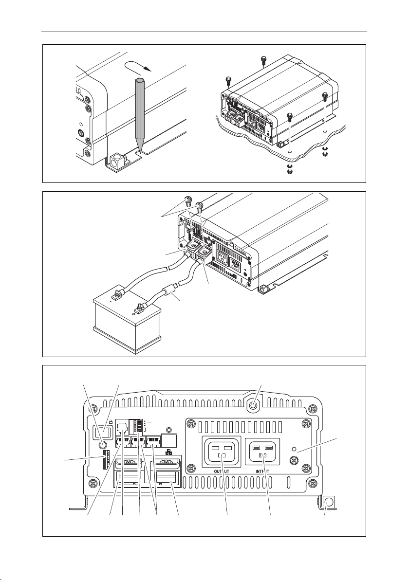
Item Description Description
6 AC input 230 Vw input jack
7 AC output 230 Vw output jack
8 Earth terminal Earthing on the vehicle bodywork
9 POS+ Positive terminal
10 CAN1 and CAN2 port CAN BUS connections
11 Green terminal Setup of remote switch and parallel operation
12 RS-232 port, REMOTE port Connection of a PC using a serial RS-232
interface or connection of the MCR7 or
MCR9 remote control
13 NEG– Negative terminal
14 LCM Remote control connection
15

EN
Fitting the inverter SinePower
8 Fitting the inverter
8.1 Tools required
For the electrical connection you will need the following tools:
• Crimping tool
• 3multi-coloured, flexible connection cables. Determine the necessary thickness
from the table in chapter “Connecting the inverter” on page 17.
• Cable lugs and conductor sleeves
For fastening you will require the following tools:
• Machine bolts (M4) with washers and self-locking nuts or
• self-tapping screws or wood screws.
8.2 Mounting instructions
When selecting the installation location, observe the following instructions:
• The inverter can be mounted horizontally or vertically.
• The inverter must be installed in a place that is protected from moisture.
• The inverter may not be installed in the presence of flammable materials.
• The inverter may not be installed in a dusty environment.
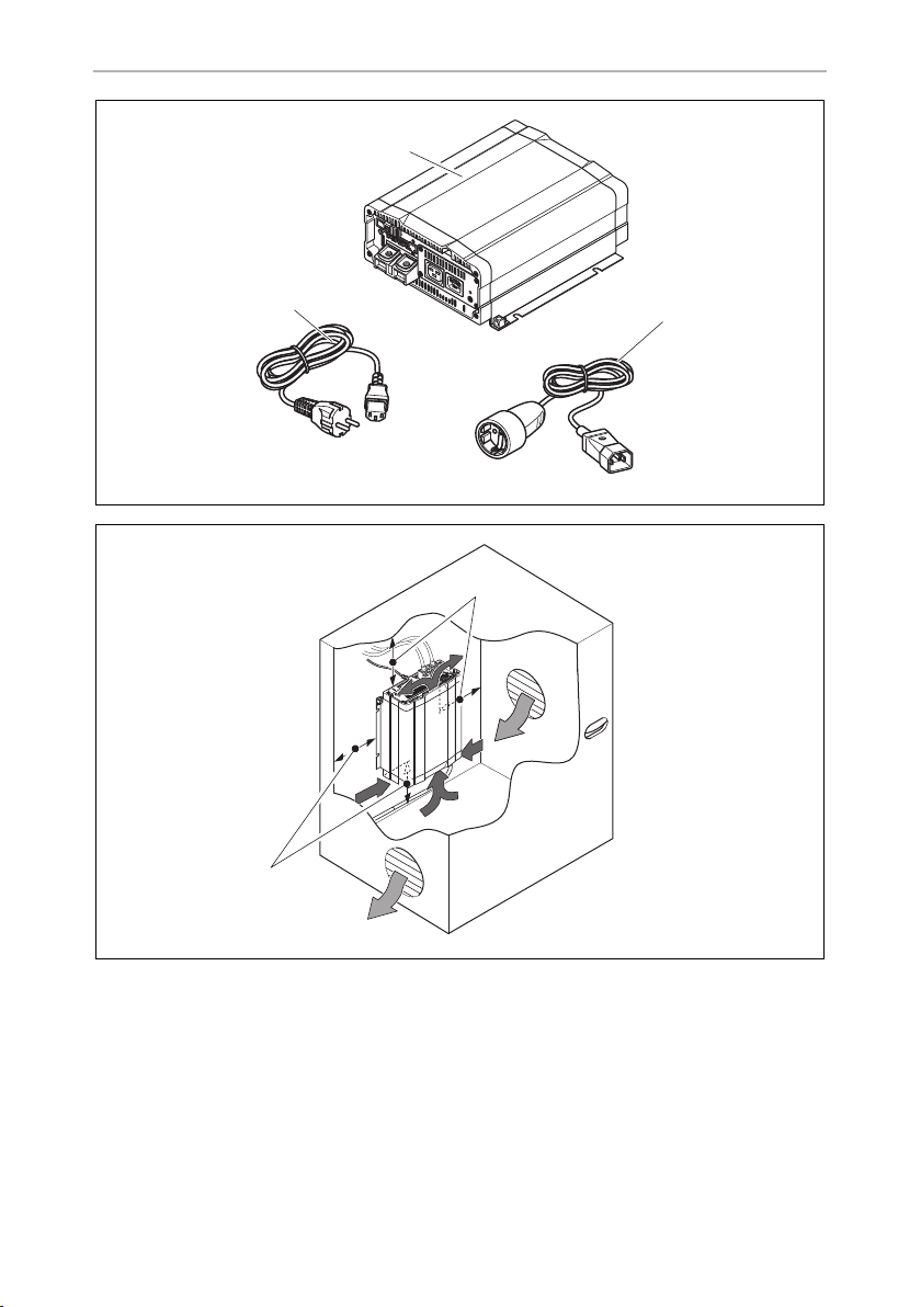
• The place of installation must be well ventilated. A ventilation system must be
available for installations in small, enclosed spaces. The minimum clearance
around the inverter must be at least 25 cm (fig. 2, page 3).
• The air intake on the underside or the air outlet on the back of the inverter must
remain clear.
• For ambient temperatures higher than 50 °C (such as in engine or heating
compartments, or direct sunlight), the heat from the inverter under load can lead
to automatic shutdown.
• The device must be installed on a level and sufficiently sturdy surface.
A
16
NOTICE!
Before drilling any holes, make sure that no electrical cables or other
parts of the vehicle can be damaged by drilling, sawing and filing.

EN
SinePower Connecting the inverter
8.3 Mounting the inverter
➤ Hold the inverter against the installation location and mark the fastening points
(fig. 3 A, page 4).
➤ Attach the inverter using your chosen fastening method (fig. 3 B, page 4).
9 Connecting the inverter
9.1 General instructions
WARNING!
!
• When installed in vehicles or boats, the inverter must be connected to the chassis
or earth.
• When setting up a socket distribution circuit (mains setup), comply with the applicable regulations.
• Only use copper cables.
• Keep the cables as short as possible (< 1 m).
• Keep to the specified cable cross section and fit a cable fuse (fig. 4 3, page 4)
as close to the battery as possible on the positive cable (see the table).
• The inverter may only be connected by a qualified workshop. The
following information is intended for technicians who are familiar
with the guidelines and safety precautions to be applied.
• Never use the inverter on vehicles where the positive terminal of the
battery is connected to the chassis.
• If you do not fit a fuse to the positive cable, the cables can over-
load, which might result in a fire.
Device
MSI2312T 70 mm² 350 A
MSI2324T 50 mm² 175 A
MSI3512T 95 mm² 400 A
MSI3524T 70 mm² 200 A
Required cable
cross section
Cable fuse
17

EN
Connecting the inverter SinePower
9.2 Connecting the inverter to the battery
NOTICE!
A
I
➤ Set the main switch (fig. 5 3, page 4) to “OFF”.
➤ Loosen the screw (fig. 4 1, page 4) from the red positive terminal (fig. 4 2,
page 4).
➤ Push the cable lug (fig. 4 2, page 4) of the positive cable into the red positive
terminal and fasten it with the bolt.
➤ Connect the negative cable to the black negative cable (fig. 4 4, page 4).
➤ Lay the positive cable from the inverter to the positive terminal of the vehicle
battery and connect it.
➤ Lay the negative cable from the inverter to the negative terminal of the vehicle
battery and connect it. A small spark can occur if the capacitors are being
charged in the inverter.
Make sure that you do not reverse the polarity. Incorrect polarity can
damage the inverter.
NOTE
Tighten the nuts and bolts to a maximum torque of 15 Nm. Loose
connections may cause overheating.
➤ Connect the earth terminal (fig. 5 8, page 4) to the vehicle chassis.
9.3 Connecting the 230 V power cable
➤ Connect the 230 Vw connection cable with safety plug (fig. 1 3, page 3) to the
230 Vw input jack (fig. 5 6, page 4).
➤ Connect the safety plug to the 230 Vw mains.
9.4 Connecting the 230 V output cable
WARNING!
!
➤ Connect the 230 Vw connection cable with safety plug (fig. 1 2, page 3) to the
230 Vw output jack (fig. 5 7, page 4).
18
Before connecting the 230 Vw output cable, make sure the inverter is
switched off at the main switch.

EN
SinePower Connecting the inverter
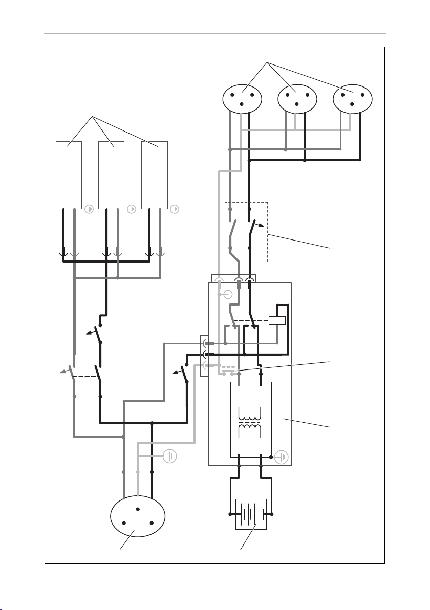
9.5 Connect multiple appliances
The device is equipped at delivery with galvanic isolation. For the safe operation of
multiple appliances, it is essential that a circuit breaker (residual current circuit
breaker) is built into the socket distribution circuit, see sample circuit diagram in
fig. 6, page 5.
Sample circuit diagram legend:
No. in
fig. 6,
page 5
!
Explanation
1 230 Vw power source
2 additional devices, e.g. battery charger, refrigerator
3 DC power source (battery)
4Inverter
5 Set grounding bridge (At delivery: not set, shown by dotted line)
6 Circuit breaker (residual current circuit breaker)
7 Socket distribution circuit for appliances
WARNING! Danger of electrocution!
If yo u wish to conn ect more than on e appliance to the inverter and install
a socket distribution circuit, you must arrange a circuit breaker (residual
current circuit breaker) and set a grounding bridge in the inverter.
➤ Install a residual current circuit breaker in the socket distribution circuit.
9.6 Setting the earthing bridge (fig. 5 5, page 4)
➤ Remove the earthing screw from the bottom hole.
➤ Screw the screw into the top hole.
19

EN
Connecting the inverter SinePower
9.7 Connecting the MCR7 or MCR9 remote control
(accessory)
NOTICE!
A
➤ Connect the remote control (accessory) to the remote port (fig. 5 12, page 4).
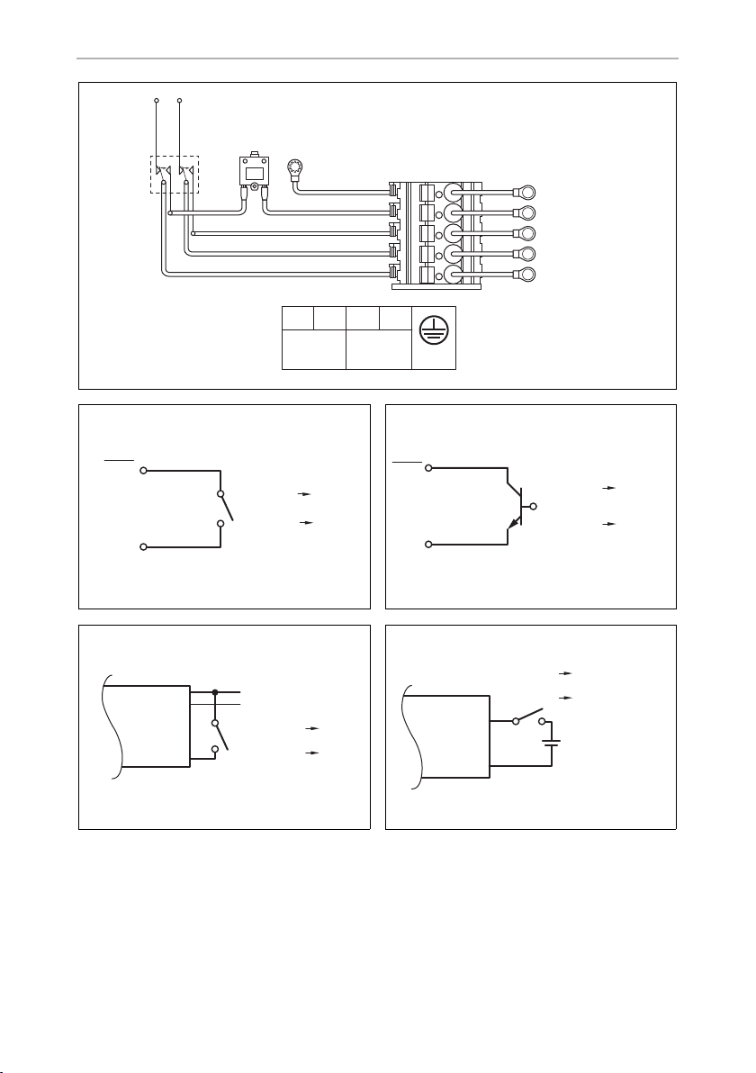
9.8 Connect external switch to turn device on and off
I
You can use the following as an external switch:
• external switch, voltage supply from the inverter: fig. 8, page 6
• Control unit with relay or transistor circuit (TR): fig. 9, page 6
• external switch with voltage supply from the battery (BAT) of the vehicle: fig. 0,
page 6
• external switch with its own voltage supply (DC POWER) e.g. from the ignition:
fig. a, page 6
• Only plug in the connection to the remote control in the remote port.
The device can be damaged by connecting it incorrectly.
• Ensure that the remote control and inverter are supplied with the
same input voltage.
• Follow the instruction manual of the remote control.
NOTE
Use cables with a cable cross section of 0.25 – 0.75 mm².
➤ Set the main switch (fig. 5 3, page 4) to “OFF” and make sure that the connec-
tion for the remote control (fig. 5 12, page 4) is not assigned.
➤ Set the main switch (fig. 5 3, page 4) to “REMOTE”.
➤ Connect the external on/off switch with the connection cable to the green
terminal (fig. 5 11, page 4).
20

EN
SinePower Connecting the inverter
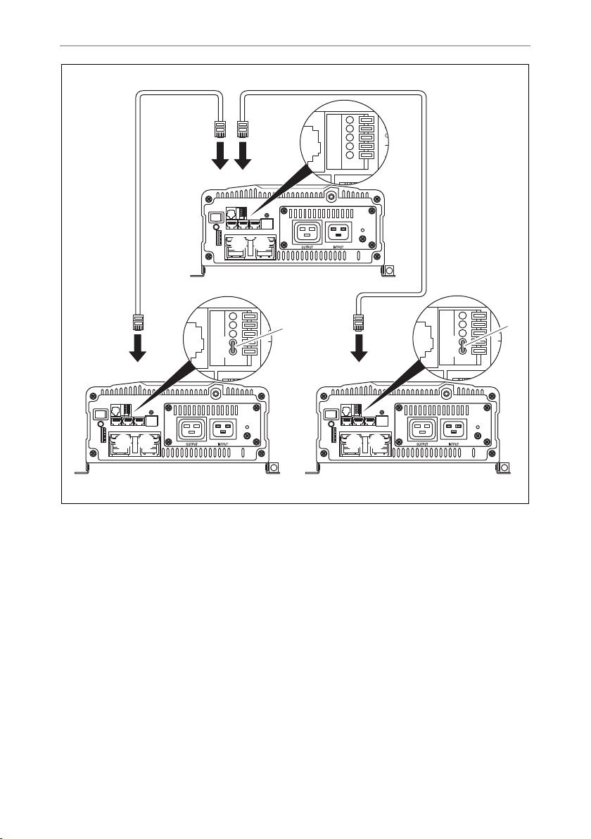
9.9 Connecting parallel operation
NOTICE!
A
➤ Set the main switch (fig. 5 3, page 4) to “OFF”.
➤ Connect the inverter according to the sample circuit diagram (fig. b, page 7).
In particular, make sure that the bridges for parallel operation are set correctly:
• Bridge removed (fig. b 1, page 7) for inverter A and set for inverter B and C.
I
• Use a cable with a cross section of 0.25 – 0.75 mm² for connecting
to the terminals for parallel operation.
• Parallel operation can only be set up using the same models (same
item number).
• A maximum of three inverters can be operated in parallel.
• The inverters operating in parallel must have the same settings for
mains voltage and mains frequency. (see chapter “Configuring the
inverter” on page 24.
NOTE
The first inverter which is switched on after installing parallel operation is
the master.
21

EN
Connecting the inverter SinePower
9.10 Pin assignment
NOTE
I
The pins of the RS-232 ports are assigned as follows:
The pins of the remote control connection are assigned as follows:
Keep the cable lengths as short as possible (< 10 m), so there is no loss
in the signal transmission.
Inverter Computer
Pin Description Description Pin
1 Not assigned Not assigned 1
2GNDGND5
3RXDTXD3
4TXDRXD2
5 Not assigned Not assigned
6 Not assigned Not assigned
Inverter Remote control
Pin Description Pin
1CANH1
2CANL2
3PON3
4VCC–4
5 VCC+ 5
6DIS6
75VS–7
85VS+8
22

EN
SinePower Using the inverter
10 Using the inverter
10.1 Switching on the inverter
➤ Set the main switch (fig. 5 3, page 4) of the inverter to the “ON” position.
Set the On/Off switch to “OFF” to switch off.
➤ The inverter performs a self-test.
During the self-test, the built-in speaker emits tones and the LED flashes.
✓ After the self-test is completed successfully, the LED lights up green (fig. 5 2,
page 4).
10.2 Status indications
The LED (fig. 5 2, page 4) shows the operating condition of the inverter.
Display Input voltage
Green, constantly lit Normal mode
Green, slow flash Energy-saving mode
Orange, quick flash Input voltage too high
Orange, slow flash Input voltage too low
Red, double flash Inverter overheated
Red, quick flash Overvoltage
Red, slow flash Undervoltage
Red, constantly lit Overload
Red, slow flash + double flash Fan fault
The inverter switches off if:
• the battery voltage drops below 10 V (12 Vg connection) or 20 V (24 Vg
connection),
• the battery voltage exceeds 16 V (12 Vg connection) or 32 V (24 Vg
connection),
• the inverter overheats.
➤ If this happens, shut down the inverter with the main switch (fig. 5 3, page 4).
23

EN
Using the inverter SinePower
➤ Check that the inverter is sufficiently ventilated and that the ventilation grilles are
unimpeded.
➤ Wait 5 – 10 minutes and switch the inverter on again without any electric
consumers.
When operating the inverter at high load for lengthy periods, it is advisable to start
the engine in order to recharge the vehicle battery.
10.3 Configuring the inverter
You can adjust the device using the DIP switch (fig. 5 1, page 4).
Setting the mains voltage
You can set the mains voltage using the S1 and S2 dip switches.
DIP switch
Mains voltage S1 S2
200 V Off Off
220 V On Off
230 V Off On
240 V On On
Setting the mains frequency
WARNING! Danger of electrocution
!
You can set the mains frequency using the S3 dip switch.
Only adjust the S3 DIP switch when the respective frequency for the
output voltage should be used.
DIP switch
Net frequency S3
50 Hz Off
60 Hz On
24

EN
SinePower Using the inverter
Switching to energy-saving mode
You can set the energy-saving mode using the S4, S5 and S6 dip switches. In this
way, the battery you connect to the inverter is not discharged as quickly.
The inverter operates in energy-saving mode as long as the required power is below
the set level. If the required power exceeds the set level, the inverter works in normal
mode.
The values to be set on your inverter can be found in the following table:
Energy-saving mode
S4 S5 S6
Off Off Off Off
2% On Off Off
3% Off On Off
4% On On Off
5% Off Off On
6% On Off On
7% Off On On
8% On On On
DIP switch
Defining settings
Using the S8 dip switch you can define whether the parameter of the setting should
be made using the connection for the remote control or the dip switches.
Dip switch
Parameter S8
Remote control connection Off
Dip switch On
25

EN
Cleaning and caring for the inverter SinePower
11 Cleaning and caring for the inverter
NOTICE!
A
➤ Occasionally clean the product with a damp cloth.
Do not use sharp or hard objects or cleaning agents for cleaning as these
may damage the product.
26

EN
SinePower Troubleshooting
12 Troubleshooting
WARNING!
!
I
The LED (fig. 5 2, page 4) lights up red to indicate the fault:
LED display Cause Remedy
Quick flash Input voltage is too high Check the input voltage and reduce it.
Slow flash Input voltage too low The battery needs recharging.
Occasional flash Overheating Switch off the inverter and the consumer.
Do not open the device. You risk sustaining an electric shock by doing
this.
NOTE
If you have detailed questions on the specifications of the inverter
please contact the manufacturer (addresses on the back of the instruction manual).
Check the cables and connections.
Wait 5 to 10 minutes and switch the inverter
on again without any electric consumers.
Reduce the load and make sure the inverter
has better ventilation. Then switch the consumer back on.
Constantly lit Short circuit or reversed
polarity
Excessive load
Switch off the inverter and remove the
consumer.
Then switch the inverter back on without the
consumer. If no excessive load is now shown,
then there is a short circuit in the consumer or
the total load was higher than the power
specified on the data sheet. The fuse in the
device must be pressed in again by hand after
it has been triggered by excess current.
Check the cables and connections.
27

EN
Warranty SinePower
13 Warranty
The statutory warranty period applies. If the product is defective, please contact the
manufacturer's branch in your country (see the back of the instruction manual for the
addresses) or your retailer.
For repair and guarantee processing, please include the following documents when
you send in the device:
• A copy of the receipt with purchasing date
• A reason for the claim or description of the fault
14 Disposal
➤ Place the packaging material in the appropriate recycling waste bins wherever
possible.
If you wish to finally dispose of the product, ask your local recycling centre
or specialist dealer for details about how to do this in accordance with the
M
applicable disposal regulations.
28

EN
SinePower Technical data
15 Technical data
MSI2312T MSI2324T MSI3512T MSI 3524T
Rated input voltage: 12 Vg 24 Vg 12 Vg 24 Vg
Output power at 25 °C for
10 min:
Peak output power: 4000 W 6000 W
Output voltage: 200 – 240 Vw pure sine wave (THD < 3%)
Output frequency: 50 or 60 Hz
Idle current consumption: 3.1 A 1.5 A 2.7 A 1.3 A
Standby current
consumption:
Input voltage range: 10.5 V – 16 V 21 V – 32 V 10.5 V – 16 V 21 V – 32 V
Efficiency up to: 92 % 92 % 92 % 92 %
Ambient temperature for
operation:
Ambient temperature for
storage
Dimensions W x D x H: 283 x 436 x 128.4 mm
Weight: 7.5 kg 9 kg
2300 W 3500 W
1.1 A0.7 A1.1 A0.7 A
–20 °C to +50 °C
–30 °C to +70 °C
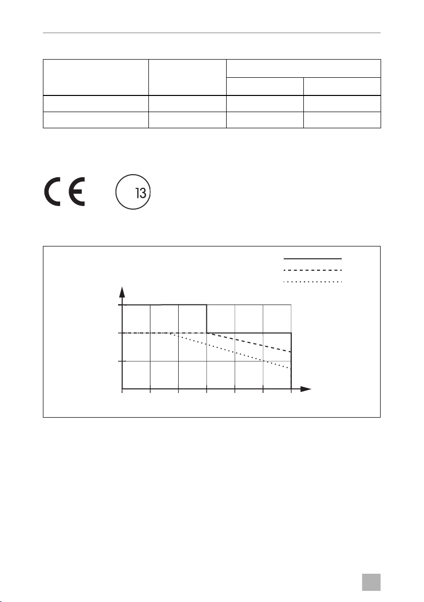
see fig. c, page 8
496 x 283 x 128.4 mm
see fig. c, page 8
Overvoltage shutdown
Device
MSI2312T, MSI3512T 15.5 V 16 V 15 V
MSI2324T, MSI3524T 31 V 32 V 30 V
Overvoltage
warning
Shutdown Restart
Overvoltage
29
EN
Technical data SinePower
W
3500
3000
2500
2520 30 35 40 45 50
°C
28 34
3000
2700
2400
>12,0 V
11,0 V
10,0 V
Undervoltage shutdown
Device
MSI2312T, MSI3512T 10.5 V 10 V 12 V
MSI2324T, MSI3524T 21.5 V 20 V 25 V
Undervoltage
warning
Shutdown Restart
Undervoltage
Approvals
The device has E13 certification.
E
Output power is dependent on ambient temperature and input voltage
30

DE
SinePower
Bitte lesen Sie diese Anleitung vor Einbau und Inbetriebnahme sorgfältig
durch und bewahren Sie sie auf. Geben Sie sie im Falle einer Weitergabe
des Produktes an den Nutzer weiter.
Inhaltsverzeichnis
1 Erklärung der Symbole . . . . . . . . . . . . . . . . . . . . . . . . . . . . . . . . . . . . . . . . . 32
2 Allgemeine Sicherheitshinweise . . . . . . . . . . . . . . . . . . . . . . . . . . . . . . . . . 32
3 Lieferumfang . . . . . . . . . . . . . . . . . . . . . . . . . . . . . . . . . . . . . . . . . . . . . . . . . 34
4 Zubehör. . . . . . . . . . . . . . . . . . . . . . . . . . . . . . . . . . . . . . . . . . . . . . . . . . . . . 34
5 Zielgruppe dieser Anleitung . . . . . . . . . . . . . . . . . . . . . . . . . . . . . . . . . . . . 35
6 Bestimmungsgemäßer Gebrauch . . . . . . . . . . . . . . . . . . . . . . . . . . . . . . . . 35
7 Technische Beschreibung . . . . . . . . . . . . . . . . . . . . . . . . . . . . . . . . . . . . . . 35
8 Wechselrichter montieren . . . . . . . . . . . . . . . . . . . . . . . . . . . . . . . . . . . . . . 38
9 Wechselrichter anschließen . . . . . . . . . . . . . . . . . . . . . . . . . . . . . . . . . . . . . 39
10 Wechselrichter benutzen . . . . . . . . . . . . . . . . . . . . . . . . . . . . . . . . . . . . . . . 46
11 Wechselrichter pflegen und reinigen . . . . . . . . . . . . . . . . . . . . . . . . . . . . . 49
12 Fehlerbeseitigung. . . . . . . . . . . . . . . . . . . . . . . . . . . . . . . . . . . . . . . . . . . . . 50
13 Gewährleistung. . . . . . . . . . . . . . . . . . . . . . . . . . . . . . . . . . . . . . . . . . . . . . . .51
14 Entsorgung . . . . . . . . . . . . . . . . . . . . . . . . . . . . . . . . . . . . . . . . . . . . . . . . . . .51
15 Technische Daten . . . . . . . . . . . . . . . . . . . . . . . . . . . . . . . . . . . . . . . . . . . . . 52
31

DE
Erklärung der Symbole SinePower
1 Erklärung der Symbole
WARNUNG!
!
A
I
Sicherheitshinweis: Nichtbeachtung kann zu Tod oder schwerer
Verletzung führen.
ACHTUNG!
Nichtbeachtung kann zu Materialschäden führen und die Funktion des
Produktes beeinträchtigen.
HINWEIS
Ergänzende Informationen zur Bedienung des Produktes.
2 Allgemeine Sicherheitshinweise
2.1 Allgemeine Sicherheit
Der Hersteller übernimmt in folgenden Fällen keine Haftung für Schäden:
• Montage- oder Anschlussfehler
• Beschädigungen am Produkt durch mechanische Einflüsse und Über-
spannungen
• Veränderungen am Produkt ohne ausdrückliche Genehmigung vom Hersteller
• Verwendung für andere als die in der Anleitung beschriebenen Zwecke
!
32
WARNUNG!
• Benutzen Sie das Gerät nur zu seinem bestimmungsgemäßen
Gebrauch.
• Betreiben Sie das Gerät nicht in feuchter oder nasser Umgebung.
• Betreiben Sie das Gerät nicht in der Nähe brennbarer Materialien.
• Betreiben Sie das Gerät nicht in explosionsgefährdeten Bereichen.
• Die Wartung und Reparatur darf nur durch eine Fachkraft geschehen,
die mit den damit verbundenen Gefahren bzw. einschlägigen Vorschriften vertraut ist.

DE
SinePower Allgemeine Sicherheitshinweise
• Personen (einschließlich Kinder), die aufgrund ihrer physischen, sensorischen oder geistigen Fähigkeiten oder ihrer Unerfahrenheit oder
Unkenntnis nicht in der Lage sind, das Produkt sicher zu benutzen,
sollten dieses Produkt nicht ohne Aufsicht oder Anweisung durch eine
verantwortliche Person nutzen.
• Elektrogeräte sind kein Kinderspielzeug!
Verwahren und benutzen Sie das Gerät außerhalb der Reichweite von
Kindern.
2.2 Sicherheit bei der Installation des Gerätes
WARNUNG!
!
A
• Die Installation des Gerätes darf ausschließlich von entsprechend aus-
gebildeten Fachbetrieben durchgeführt werden, die mit den anzuwendenden Richtlinien und Sicherheitsvorkehrungen vertraut sind.
• Bei falscher Installation elektrischer Geräte auf Booten kann es zu Korrosionsschäden am Boot kommen. Die Installation des Gerätes sollte
von einem fachkundigen (Boots-)Elektriker durchgeführt werden.
ACHTUNG!
• Achten Sie auf einen sicheren Stand!
Das Gerät muss so sicher aufgestellt und befestigt werden, dass es
nicht umstürzen oder herabfallen kann.
• Setzen Sie das Gerät keiner Wärmequelle (Sonneneinstrahlung, Heizung usw.) aus. Vermeiden Sie so zusätzliche Erwärmung des Gerätes.
• Müssen Leitungen durch Blechwände oder andere scharfkantige
Wände geführt werden, benutzen Sie Leerrohre bzw. Leitungsdurchführungen.
• Verlegen Sie Leitungen nicht lose oder scharf abgeknickt an elektrisch
leitenden Materialien (Metall).
• Ziehen Sie nicht an Leitungen.
• Verlegen Sie 230-V-Netzleitung und 12/24-V-Gleichstromleitung
nicht zusammen im gleichen Leitungskanal (Leerrohr).
• Befestigen Sie die Leitungen gut.
• Verlegen Sie die Leitungen so, dass keine Stolpergefahr entsteht und
eine Beschädigung des Kabels ausgeschlossen ist.
33

DE
Lieferumfang SinePower
2.3 Sicherheit beim Betrieb des Gerätes
WARNUNG!
!
A
• Betreiben Sie das Gerät nur, wenn das Gehäuse und die Leitungen
unbeschädigt sind.
• Auch nach Auslösen der Schutzeinrichtung (Sicherung) bleiben Teile
des Wechselrichters unter Spannung.
• Unterbrechen Sie bei Arbeiten am Gerät immer die Stromversorgung.
ACHTUNG!
• Achten Sie darauf, dass Luftein- und ausgänge des Geräts nicht verdeckt werden.
• Achten Sie auf gute Belüftung. Der Wechselrichter produziert Verlustwärme, die abgeführt werden muss.
• Verbinden Sie den 230-V-Ausgang des Wechselrichters (Abb. 5 7,
Seite 4) nicht mit einer anderen 230-V-Quelle.
3 Lieferumfang
Pos. in
Abb. 1,
Seite 3
Bezeichnung
1 Sinus Wechselrichter
2 Anschlusskabel mit Schuko-Kupplung
(für 230-Vw-Ausgang)
3 Anschlusskabel mit Schuko-Stecker
(für 230-Vw-Versorgung)
– Bedienungsanleitung
4Zubehör
Bezeichnung Art.-Nr.
Fernbedienung MCR7 9600000090
Fernbedienung MCR9 9600000091
34

DE
SinePower Zielgruppe dieser Anleitung
5 Zielgruppe dieser Anleitung
Das Kapitel „Wechselrichter anschließen“ auf Seite 39 wendet sich ausschließlich an
Fachleute, die mit den entsprechenden VDE-Richtlinien vertraut sind.
Alle übrigen Kapitel wenden sich auch an die Benutzer des Gerätes.
6 Bestimmungsgemäßer Gebrauch
WARNUNG!
!
Die Wechselrichter dienen dazu, Gleichspannung von
• 12 Vg (MSI2312T, MSI3512T)
• 24 Vg (MSI 2324T, MSI3524T)
in eine 200 – 240-V-Wechselspannung von 50 Hz oder 60 Hz zu wandeln.
Der Wechselrichter darf nicht in Fahrzeugen eingesetzt werden, bei
denen der Plus-Pol der Batterie mit dem Chassis verbunden ist.
7 Technische Beschreibung
Die Wechselrichter lassen sich überall dort betreiben, wo
• ein 12-Vg-Anschluss (MSI2312T, MSI3512T)
• ein 24-Vg-Anschluss (MSI2324T, MSI3524T)
vorhanden ist. Durch das geringe Gewicht und die kompakte Bauweise lässt sich
dieses Gerät problemlos in Reisemobilen, Nutzfahrzeugen oder Motor- und
Segelyachten einbauen.
Die Ausgangsspannung entspricht der Haushaltsspannung aus der Steckdose (reine
Sinusspannung, THD < 3%).
Bitte beachten Sie die Werte für Dauer-Ausgangsleistung und Spitzen-Ausgangsleistung, wie sie im Kapitel Kapitel „Technische Daten“ auf Seite 52 angegeben sind.
Geräte, die einen höheren Leistungsbedarf haben, dürfen nicht angeschlossen
werden.
HINWEIS
I
Beachten Sie beim Anschluss von Geräten mit elektrischem Antrieb
(z. B. Bohrmaschine, Kühlschrank usw.), dass diese zum Anlaufen oft
eine höhere Leistung benötigen, als auf dem Typenschild angegeben.
35

DE
Technische Beschreibung SinePower
Der Wechselrichter besitzt verschiedene Schutzmechanismen:
• Überspannungs-Schutz: Der Wechselrichter schaltet ab, wenn der
Spannungswert über den Abschalt-Wert steigt. Er startet wieder, wenn die
Spannung auf den Neustart-Wert sinkt.
• Unterspannungs-Schutz: Der Wechselrichter schaltet ab, wenn der
Spannungswert unter den Abschalt-Wert sinkt. Er startet wieder, wenn die
Spannung auf den Neustart-Wert steigt.
• Übertemperatur-Schutz: Der Wechselrichter schaltet ab, wenn die
Temperatur innerhalb des Gerätes oder die Temperatur an dem Kühlkörper
einen Abschalt-Wert übersteigt. Er startet wieder, wenn die Spannung auf den
Neustart-Wert steigt.
• Überlast-Schutz und Schutz vor Kurzschluss: Die LED am Wechselrichter
meldet eine Betriebsstörung (rotes Dauerlicht), wenn eine zu große Last angeschlossen ist oder ein Kurzschluss erzeugt wurde. Die Gerätesicherung muss,
nachdem sie bei Überstrom ausgelöst hat, manuell wieder eingedrückt werden.
• Verpolungsschutz: Der Verpolungsschutz verhindert beim Anschluss des
Wechselrichter eine falsche Polarität.
HINWEIS
I
Die einzelnen Schaltwerte finden Sie im Kapitel Kapitel „Technische
Daten“ auf Seite 52.
Die Wechselrichter verfügen über eine 230-Vw-Steckdose und eine Anschlussklemmleiste für Festanschluss.
Durch die Spannungssynchronisierung mit der AC-Eingangsspannung eignet sich
der Wechselrichter für den Betrieb empfindlicher Verbraucher, die auf Unregelmäßigkeiten in der Versorgungsspannung reagieren.
Zusätzlich kann das Gerät über eine RS-232-Schnittstelle durch einen PC und mit
den DIP-Schaltern am Gerät konfiguriert werden.
Der Wechselrichter kann in einen Energiesparmodus geschaltet werden, damit die
angeschlossene Batterie nicht zu schnell entlädt.
Der Parallelbetrieb ermöglicht es, zwei bis maximal drei Wechselrichter (gleiche
Modelle) gleichzeitig zu betreiben.
Mit einer Fernbedienung (Zubehör) kann der Wechselrichter bequem gesteuert
werden.
36

DE
SinePower Technische Beschreibung
7.1 Bedienelemente
Bedienelemente des Wechselrichters (Abb. 5, Seite 4)
Pos. Bezeichnung Beschreibung
1 Dipschalter Nimmt Einstellungen am Wechselrichter vor
(z. B. Netzspannung, Netzfrequenz, Energiesparmodus)
2 LED Siehe Kapitel „Betriebsanzeigen“ auf Seite 46
3 Hauptschalter
„ON/OFF/REMOTE“
4 Sicherung Schützt den Wechselrichter vor Überlastung.
5 Erdungsschraube Setzt oder entfernt die Erdungsbrücke
Schaltet das Gerät ein, aus oder in den
Betrieb über die Fernbedienung (Zubehör)
Die Sicherung kann wieder eingedrückt
werden, nachdem sie ausgelöst hat.
7.2 Anschlüsse
HINWEIS
I
Anschlüsse des Wechselrichters (Abb. 5, Seite 4)
Abgebildet ist die Version für Kontinentaleuropa.
Pos. Bezeichnung Beschreibung
6AC Input 230-Vw-Eingangsbuchse
7 AC Output 230-Vw-Ausgangsbuchse
8 Masse-Klemme Erdung an der Fahrzeugkarosserie
9 POS+ Plus-Klemme
10 CAN1- und CAN2-Port CAN-BUS-Anschlüsse
11 Grüne Klemme Einrichtung von Fernschalter und
Parallelbetrieb
12 RS-232-Schnittstelle,
REMOTE-Port
13 NEG– Minus-Klemme
14 LCM Anschluss für Fernbedienung
Anschluss eines PCs über eine serielle
RS-232-Schnittstelle oder Anschluss der
Fernbedienung MCR7, MCR9
37

DE
Wechselrichter montieren SinePower
8 Wechselrichter montieren
8.1 Benötigtes Werkzeug
Für den elektrischen Anschluss benötigen Sie folgende Hilfsmittel:
• Krimpzange
• 3 verschiedenfarbige flexible Anschlusskabel. Den erforderlichen Querschnitt
entnehmen Sie der Tabelle im Kapitel Kapitel „Wechselrichter anschließen“ auf
Seite 39.
• Kabelschuhe und Aderendhülsen
Für die Befestigung des Wechselrichters benötigen Sie folgende Montagemittel:
• Maschinenschrauben (M4) mit Unterlegscheiben und selbstsichernden Muttern
oder
• Blech- bzw. Holzschrauben.
8.2 Montagehinweise
Beachten Sie bei der Wahl des Montageortes folgende Hinweise:
• Die Montage des Wechselrichters kann horizontal wie auch vertikal erfolgen.
• Der Wechselrichter muss an einer vor Feuchtigkeit geschützten Stelle eingebaut
werden.
• Der Wechselrichter darf nicht in Umgebungen mit entflammbaren Materialien
eingebaut werden.
• Der Wechselrichter darf nicht in staubigen Umgebungen eingebaut werden.
• Der Einbauort muss gut belüftet sein. Bei Installationen in geschlossenen kleinen
Räumen sollte eine Be- und Entlüftung vorhanden sein. Der freie Mindestabstand
um den Wechselrichter muss mindestens 25 cm betragen (Abb. 2, Seite 3).
• Der Lufteintritt auf der Unterseite bzw. der Luftaustritt auf der Rückseite des
Wechselrichters muss freibleiben.
• Bei Umgebungstemperaturen, die höher als 50 °C (z. B. in Motor- oder
Heizungsräumen, direkte Sonneneinstrahlung) sind, kann es durch die Eigenerwärmung des Wechselrichters bei Belastung zum automatischen Abschalten
kommen.
• Die Montagefläche muss eben sein und eine ausreichende Festigkeit aufweisen.
38

DE
SinePower Wechselrichter anschließen
ACHTUNG!
A
Bevor Sie irgendwelche Bohrungen vornehmen, stellen Sie sicher, dass
keine elektrischen Kabel oder andere Teile des Fahrzeugs durch Bohren, Sägen und Feilen beschädigt werden.
8.3 Wechselrichter montieren
➤ Halten Sie den Wechselrichter an den von Ihnen gewählten Einbauort und
markieren Sie die Befestigungspunkte (Abb. 3 A, Seite 4).
➤ Befestigen Sie den Wechselrichter mit der von Ihnen gewählten Befestigungs-
methode (Abb. 3 B, Seite 4).
9 Wechselrichter anschließen
9.1 Allgemeine Hinweise
WARNUNG!
!
• Der Anschluss des Wechselrichters darf ausschließlich von
entsprechend ausgebildeten Fachbetrieben durchgeführt werden.
Die nachfolgenden Informationen richten sich an Fachkräfte, die mit
den anzuwendenden Richtlinien und Sicherheitsvorkehrungen
vertraut sind.
• Bei Fahrzeugen, bei denen der Plus-Pol der Batterie mit dem Chassis
verbunden ist, darf der Wechselrichter nicht eingesetzt werden.
• Wenn Sie keine Sicherung in die Plus-Leitung der Batterie setzen,
können die Leitungen überlastet werden, und es kann zu einem
Brand kommen.
• Der Wechselrichter muss bei Installationen in Fahrzeugen oder Booten mit dem
Chassis bzw. der Masse verbunden sein.
• Halten Sie beim Aufbau eines Steckdosenverteilerkreises (Netzaufbau) die
Vorschriften der VDE 0100 ein.
• Verwenden Sie ausschließlich Kupferkabel.
• Halten Sie die Kabel so kurz wie möglich (< 1 m).
39

DE
Wechselrichter anschließen SinePower
• Halten Sie den erforderlichen Kabelquerschnitt ein und setzen Sie eine Kabelsicherung (Abb. 4 3, Seite 4) möglichst nah an der Batterie in die Plus-Leitung
(siehe Tabelle).
Gerät
MSI2312T 70 mm² 350 A
MSI2324T 50 mm² 175 A
MSI3512T 95 mm² 400 A
MSI3524T 70 mm² 200 A
Erforderlicher
Kabelquerschnitt
Kabelsicherung
9.2 Wechselrichter an Batterie anschließen
ACHTUNG!
A
I
➤ Stellen Sie den Hauptschalter (Abb. 5 3, Seite 4) auf „OFF“.
➤ Lösen Sie die Schraube (Abb. 4 1, Seite 4) aus der roten Plus-Klemme
(Abb. 4 2, Seite 4).
➤ Schieben Sie den Kabelschuh (Abb. 4 2, Seite 4) des Plus-Kabels in die rote
Plus-Klemme und befestigen Sie ihn mit der Schraube.
Achten Sie darauf, dass die Polarität nicht vertauscht wird. Falsche
Polarität kann den Wechselrichter beschädigen.
HINWEIS
Ziehen Sie die Schrauben oder Muttern mit einem Drehmoment von
max. 15 Nm fest. Lose Verbindungen können zu Überhitzungen führen.
➤ Schließen Sie das Minus-Kabel entsprechend an der schwarzen Minus-Klemme
(Abb. 4 4, Seite 4) an.
➤ Verlegen Sie das Plus-Kabel vom Wechselrichters zum Pluspol der Fahrzeug-
Batterie und schließen Sie es dort an.
➤ Verlegen Sie das Minus-Kabel vom Wechselrichters zum Minuspol der Fahrzeug-
Batterie und schließen Sie es dort an. Ein kleiner Funke kann entstehen, wenn die
Kondensatoren im Wechselrichter aufgeladen sind.
➤ Verbinden Sie die Masse-Klemme (Abb. 5 8, Seite 4) mit der Fahrzeug-
karosserie.
40

DE
SinePower Wechselrichter anschließen
9.3 230-V-Versorgungsleitung anschließen
➤ Stecken Sie das 230-Vw-Anschlusskabel mit Schuko-Stecker (Abb. 1 3,
Seite 3) in die 230-Vw-Eingangsbuchse (Abb. 5 6, Seite 4).
➤ Schließen Sie den Schuko-Stecker an das 230-V-Wechselstromnetz an.
9.4 230-V-Ausgangsleitung anschließen
WARNUNG!
!
➤ Stecken Sie das 230-Vw-Anschlusskabel mit Schuko-Kupplung (Abb. 1 2,
Seite 3) in die 230-Vw-Ausgangsbuchse (Abb. 5 7, Seite 4).
Stellen Sie vor dem Anschließen der 230-Vw-Ausgangsleitung sicher,
dass der Wechselrichter mit dem Hauptschalter ausgeschaltet ist.
9.5 Mehrere Verbraucher anschließen
Das Gerät ist im Lieferzustand mit galvanischer Trennung ausgestattet. Zum sicheren
Betrieb von mehreren Verbrauchern ist es zwingend notwendig, dass im
Steckdosenverteilerkreis ein Schutzschalter (FI-Schalter) eingebaut wird, siehe
Beispiel-Schaltplan in Abb. 6, Seite 5.
Legende zum Beispiel-Schaltplan:
Pos. in
Abb. 6,
Seite 5
Erklärung
1 230-Vw-Spannungsquelle
2 weitere Geräte wie z. B. Batterielader, Kühlschrank
3 DC-Spannungsquelle (Batterie)
4 Wechselrichter
5 Erdungsbrücke gesetzt (Lieferzustand: nicht gesetzt, gestrichelt dargestellt)
6 Schutzschalter (FI-Schalter)
7 Steckdosenverteilerkreis für Verbraucher
41

DE
Wechselrichter anschließen SinePower
WARNUNG! Lebensgefahr durch Stromschlag!
!
➤ Bauen Sie einen FI-Schalter in den Steckdosenverteilerkreis ein.
9.6 Erdungsbrücke setzen (Abb. 5 5, Seite 4)
➤ Schrauben Sie die Erdungsschraube aus der unteren Bohrung heraus.
➤ Schrauben Sie die Schraube in die obere Bohrung ein.
9.7 Fernbedienung MCR7 oder MCR9 (Zubehör)
A
Wenn Sie mehr als einen Verbraucher an den Wechselrichter
anschließen wollen und dazu einen Steckdosenverteilerkreis aufbauen,
müssen Sie einen Schutzschalter (FI-Schalter) vorsehen und die
Erdungsbrücke im Wechselrichter setzen.
anschließen
ACHTUNG!
• Stecken Sie den Anschluss zur Fernbedienung nur in den RemotePort. Durch falsches Anschließen kann das Gerät beschädigt
werden.
• Stellen Sie sicher, dass Fernbedienung und Wechselrichter mit
demselben Eingangsspannungswert versorgt werden.
• Beachten Sie die Anleitung der Fernbedienung.
➤ Schließen Sie die Fernbedienung (Zubehör) am Remote-Port (Abb. 5 12,
Seite 4) an.
42

DE
SinePower Wechselrichter anschließen
9.8 Externen Schalter zum Ein- und Ausschalten
anschließen
HINWEIS
I
Als externen Schalter können Sie folgendes verwenden:
• externer Schalter, Spannungsversorgung aus dem Wechselrichter: Abb. 8,
Seite 6
• Steuereinheit mit Relais- oder Transistorbeschaltung (TR): Abb. 9, Seite 6
• externer Schalter mit Spannungsversorgung über die Batterie (BAT) des
Fahrzeuges: Abb. 0, Seite 6
• externer Schalter mit eigener Spannungsversorgung (DC POWER), z. B. von der
Zündung: Abb. a, Seite 6
➤ Stellen Sie den Hauptschalter (Abb. 5 3, Seite 4) auf „OFF“ und stellen Sie
sicher, dass der Anschluss für die Fernbedienung (Abb. 5 12, Seite 4) nicht
belegt ist.
➤ Stellen Sie den Hauptschalter (Abb. 5 3, Seite 4) auf „REMOTE“.
➤ Schließen Sie den externen Ein-/Aus-Schalter mit dem Anschlusskabel an der
grünen Klemme (Abb. 5 11, Seite 4) an.
Verwenden Sie Kabel mit einem Kabelquerschnitt von 0,25 – 0,75 mm².
43

DE
Wechselrichter anschließen SinePower
9.9 Parallelbetrieb anschließen
ACHTUNG!
A
➤ Stellen Sie den Hauptschalter (Abb. 5 3, Seite 4) auf „OFF“.
➤ Schließen Sie die Wechselrichter nach dem Beispiel-Schaltplan an (Abb. b,
Seite 7).
Achten Sie besonders darauf, dass die Brücken für den Parallelbetrieb richtig gesetzt
sind:
• Brücke (Abb. b 1, Seite 7) bei Wechselrichter A entfernt, bei Wechselrichter B
und C gesetzt.
I
• Verwenden Sie für den Anschluss an die Klemmen für den
Parallelbetrieb Kabel mit einem Kabelquerschnitt von
0,25 – 0,75 mm².
• Der Parallelbetrieb kann nur bei gleichen Modellen (gleiche
Artikelnummer) eingerichtet werden.
• Es können maximal drei Wechselrichter parallel betrieben werden.
• Die parallel betriebenen Wechselrichter müssen die gleichen Ein-
stellungen für Netzspannung und Netzfrequenz haben (siehe Kapitel
Kapitel „Wechselrichter einstellen“ auf Seite 47.
HINWEIS
Der erste Wechselrichter, der nach Installation des Parallelbetriebs
eingeschaltet wird, ist der Master.
44

DE
SinePower Wechselrichter anschließen
9.10 Pin-Belegungen
HINWEIS
I
Die Pins des RS-232-Ports sind wie folgt belegt:
Die Pins des Anschlusses für Fernbedienung sind wie folgt belegt:
Halten Sie die Kabellängen so kurz wie möglich (< 10 m), damit es keine
Verluste bei der Signalübertragung gibt.
Wec hse lri chte r Computer
Pin Beschreibung Beschreibung Pin
1 Nicht belegt Nicht belegt 1
2GNDGND5
3RXDTXD3
4TXDRXD2
5 Nicht belegt Nicht belegt
6 Nicht belegt Nicht belegt
Wec hs elr ich te r Fernbedienung
Pin Beschreibung Pin
1CANH1
2CANL2
3PON3
4VCC–4
5 VCC+ 5
6DIS6
75VS–7
85VS+8
45

DE
Wechselrichter benutzen SinePower
10 Wechselrichter benutzen
10.1 Wechselrichter einschalten
➤ Stellen Sie den Hauptschalter (Abb. 5 3, Seite 4) des Wechselrichters in
Schalterstellung „ON“.
Zum Ausschalten stellen Sie den Ein/Aus-Schalter auf „OFF“.
➤ Der Wechselrichter führt einen Selbsttest durch.
Während der Selbstdiagnose gibt der interne Lautsprecher Töne ab und die LED
blinkt.
✓ Nach dem erfolgreichen Selbsttest leuchtet die LED grün (Abb. 5 2, Seite 4).
10.2 Betriebsanzeigen
Die LED (Abb. 5 2, Seite 4) zeigt den Betriebszustand des Wechselrichters an.
Anzeige Eingangsspannung
Grün, Dauerleuchten Normalbetrieb
Grün, langsames Blinken Energiesparmodus
Orange, schnelles Blinken Eingangsspannung zu hoch
Orange, langsames Blinken Eingangsspannung zu niedrig
Rot, Doppel-Blinken Wechselrichter überhitzt
Rot, schnelles Blinken Überspannung
Rot, langsames Blinken Unterspannung
Rot, Dauerleuchten Überlastung
Rot, langsames Blinken + Doppel-Blinken Lüfterfehler
Der Wechselrichter schaltet sich ab, wenn
• die Batteriespannung unter 10 V (12 Vg-Anschluss) bzw. 20 V (24 VgAnschluss) sinkt,
• die Batteriespannung über 16 V (12 Vg-Anschluss) bzw. 32 V (24 VgAnschluss) steigt,
• der Wechselrichter überhitzt wird.
46

DE
SinePower Wechselrichter benutzen
➤ Schalten Sie den Wechselrichter in diesem Fall mit dem Hauptschalter
(Abb. 5 3, Seite 4) aus.
➤ Kontrollieren Sie, ob der Wechselrichter genügend belüftet ist und ob die Lüfter-
öffnungen und Belüftungsschlitze frei sind.
➤ Warten Sie ca. 5 – 10 min und schalten Sie den Wechselrichter ohne Verbraucher
wieder ein.
Beim Betreiben des Wechselrichters über längere Zeit und mit größter Belastung
empfiehlt es sich, den Motor zu starten, um die Batterie des Fahrzeuges wieder aufzuladen.
10.3 Wechselrichter einstellen
Sie können das Gerät mit Hilfe der DIP-Schalter (Abb. 5 1, Seite 4) anpassen.
Netzspannung einstellen
Mit den Dip-Schaltern S1 und S2 können Sie die Netzspannung einstellen.
Dip-Schalter
Netzspannung S1 S2
200 V Aus Aus
220 V Ein Aus
230 V Aus Ein
240 V Ein Ein
Netzfrequenz einstellen
WARNUNG! Lebensgefahr durch Stromschlag!
!
Mit dem Dip-Schalter S3 können Sie die Netzfrequenz einstellen.
Verstellen Sie DIP-Schalter S3 nur, wenn die entsprechende Frequenz
für die Ausgangsspannung verwendet werden soll.
Dip-Schalter
Netzfrequenz S3
50 Hz Aus
60 Hz Ein
47

DE
Wechselrichter benutzen SinePower
Energiesparmodus einstellen
Mit den Dip-Schaltern S4, S5 und S6 können Sie den Energiesparmodus einstellen.
Dadurch wird die Batterie, an der Sie den Wechselrichter anschließen, nicht so
schnell entladen.
Der Wechselrichter arbeitet dann im Energiesparmodus, solange die geforderte
Leistung unter dem eingestellten Leistungswert liegt. Wenn die benötigte Leistung
über dem eingestellten Leistungswert liegt, arbeitet der Wechselrichter im Normalbetrieb.
Die einzustellenden Werte für Ihren Wechselrichter entnehmen Sie bitte der
folgenden Tabelle:
Energiesparmodus
S4 S5 S6
Aus Aus Aus Aus
2% Ein Aus Aus
3% Aus Ein Aus
4% Ein Ein Aus
5% Aus Aus Ein
6% Ein Aus Ein
7% Aus Ein Ein
8% Ein Ein Ein
Dip-Schalter
Einstellungen festlegen
Mit dem Dipschalter S8 können Sie festlegen, ob die Einstellung der Parameter über
den Anschluss für Fernbedienung oder über die Dip-Schalter erfolgen soll.
Dip-Schalter
Parameter S8
Anschluss für Fernbedienung Aus
Dip-Schalter Ein
48

DE
SinePower Wechselrichter pflegen und reinigen
11 Wechselrichter pflegen und reinigen
ACHTUNG!
A
➤ Reinigen Sie das Produkt gelegentlich mit einem feuchten Tuch.
Keine scharfen oder harten Gegenstände oder Reinigungsmittel zur
Reinigung verwenden, da dies zu einer Beschädigung des Produktes
führen kann.
49

DE
Fehlerbeseitigung SinePower
12 Fehlerbeseitigung
WARNUNG!
!
I
Die LED (Abb. 5 2, Seite 4) zeigt rot den Fehler an:
LED-Anzeige Ursache Behebung
Öffnen Sie das Gerät nicht. Sie setzen sich der Gefahr eines elektrischen
Schlages aus!
HINWEIS
Bei detaillierten Fragen zu den Daten des Wechselrichters wenden
Sie sich bitte an den Hersteller (Adressen siehe Rückseite der Anleitung).
Schnelles Blinken Zu hohe Eingangs-
spannung
Langsames Blinken Zu niedrige Eingangs-
spannung
Periodisches Blinken Thermische Überlastung Schalten Sie den Wechselrichter und
Dauerleuchten Kurzschluss oder
Verpolung
Zu hohe Belastung
Prüfen Sie die Eingangsspannung und
reduzieren Sie diese.
Die Batterie muss nachgeladen werden.
Prüfen Sie die Leitungen und Verbin-
dungen.
den Verbraucher aus.
Warten Sie ca. 5 – 10minuten und
schalten Sie den Wechselrichter ohne
Verbraucher wieder ein.
Reduzieren Sie die Belastung und
sorgen Sie für eine bessere Belüftung
des Wechselrichters. Schalten Sie dann
den Verbraucher wieder ein.
Schalten Sie den Wechselrichter aus
und entfernen Sie den Verbraucher.
Schalten Sie den Wechselrichter ohne
Verbraucher wieder ein. Wird jetzt keine
zu hohe Belastung mehr angezeigt, so
liegt ein Kurzschluss beim Verbraucher
vor oder die Gesamtbelastung war
höher als die im Datenblatt spezifizierte
Leistung. Die Gerätesicherung muss,
nachdem sie bei Überstrom ausgelöst
hat, manuell wieder eingedrückt
werden.
Prüfen Sie die Leitungen und
Verbindungen.
50

DE
SinePower Gewährleistung
13 Gewährleistung
Es gilt die gesetzliche Gewährleistungsfrist. Sollte das Produkt defekt sein, wenden
Sie sich bitte an die Niederlassung des Herstellers in Ihrem Land (Adressen siehe
Rückseite der Anleitung) oder an Ihren Fachhändler.
Zur Reparatur- bzw. Gewährleistungsbearbeitung müssen Sie folgende Unterlagen
mitschicken:
• eine Kopie der Rechnung mit Kaufdatum,
• einen Reklamationsgrund oder eine Fehlerbeschreibung.
14 Entsorgung
➤ Geben Sie das Verpackungsmaterial möglichst in den entsprechenden
Recycling-Müll.
Wenn Sie das Produkt endgültig außer Betrieb nehmen, informieren Sie
sich bitte beim nächsten Recyclingcenter oder bei Ihrem Fachhändler
M
über die zutreffenden Entsorgungsvorschriften.
51

DE
Technische Daten SinePower
15 Technische Daten
MSI2312T MSI 2324T MSI 3512T MSI3524T
Eingangsnennspannung: 12 Vg 24 Vg 12 Vg 24 Vg
Ausgangsleistung
bei 25 °C für 10 min:
Spitzen-Ausgangsleistung: 4000 W 6000 W
Ausgangsspannung: 200 – 240 Vw reine Sinuswelle (THD < 3%)
Ausgangsfrequenz: 50 oder 60 Hz
Leerlaufstromaufnahme: 3,1 A 1,5 A 2,7 A 1,3 A
Bereitschaftstromaufnahme:1,1 A0,7 A1,1 A0,7 A
Eingangsspannungsbereich: 10,5 V – 16 V 21 V – 32 V 10,5 V – 16 V 21 V – 32 V
Wirkungsgrad bis zu: 92 % 92 % 92 % 92 %
Umgebungstemperatur
Betrieb:
Umgebungstemperatur
Lagerung:
Abmessungen B x T x H: 283 x 436 x 128,4 mm
Gewicht: 7,5 kg 9 kg
2300 W 3500 W
–20 °C bis +50 °C
–30 °C bis +70 °C
siehe Abb. c, Seite 8
283 x 496 x 128,4 mm
siehe Abb. c, Seite 8
Überspannungs-Schutz
Gerät
MSI2312T, MSI3512T 15,5 V 16 V 15 V
MSI2324T, MSI3524T 31 V 32 V 30 V
Überspannungs-
warnung
Abschaltung Neustart
Überspannung
Unterspannungs-Schutz
Gerät
MSI2312T, MSI3512T 10,5 V 10 V 12 V
MSI2324T, MSI3524T 21,5 V 20 V 25 V
Unterspannungs-
warnung
Abschaltung Neustart
Unterspannung
52

DE
SinePower Technische Daten
Zulassungen
Das Gerät hat die E13-Zulassung.
E
Ausgangsleistung in Abhängigkeit von Umgebungstemperatur und
Eingangsspannung
>12,0 V
11,0 V
W
3500
10,0 V
3000
2500
28 34
2520 30 35 40 45 50
3000
2700
2400
°C
53

FR
SinePower
Veuillez lire attentivement cette notice avant le montage et la mise en
service. Veuillez ensuite la conserver. En cas de passer le produit, veuillez
le transmettre au nouvel acquéreur.
Sommaire
1 Explication des symboles . . . . . . . . . . . . . . . . . . . . . . . . . . . . . . . . . . . . . . . 55
2 Consignes générales de sécurité . . . . . . . . . . . . . . . . . . . . . . . . . . . . . . . . . 55
3 Pièces fournies . . . . . . . . . . . . . . . . . . . . . . . . . . . . . . . . . . . . . . . . . . . . . . . 57
4 Accessoires . . . . . . . . . . . . . . . . . . . . . . . . . . . . . . . . . . . . . . . . . . . . . . . . . . 57
5 Groupe cible de cette notice . . . . . . . . . . . . . . . . . . . . . . . . . . . . . . . . . . . . 58
6 Usage conforme . . . . . . . . . . . . . . . . . . . . . . . . . . . . . . . . . . . . . . . . . . . . . . 58
7 Description technique . . . . . . . . . . . . . . . . . . . . . . . . . . . . . . . . . . . . . . . . . 58
8 Montage de l'onduleur. . . . . . . . . . . . . . . . . . . . . . . . . . . . . . . . . . . . . . . . . .61
9 Raccordement de l'onduleur . . . . . . . . . . . . . . . . . . . . . . . . . . . . . . . . . . . . 63
10 Utilisation de l'onduleur . . . . . . . . . . . . . . . . . . . . . . . . . . . . . . . . . . . . . . . . 69
11 Entretien et nettoyage de l'onduleur . . . . . . . . . . . . . . . . . . . . . . . . . . . . . . 72
12 Élimination des erreurs . . . . . . . . . . . . . . . . . . . . . . . . . . . . . . . . . . . . . . . . . 73
13 Garantie. . . . . . . . . . . . . . . . . . . . . . . . . . . . . . . . . . . . . . . . . . . . . . . . . . . . . 74
14 Retraitement . . . . . . . . . . . . . . . . . . . . . . . . . . . . . . . . . . . . . . . . . . . . . . . . . 74
15 Caractéristiques techniques . . . . . . . . . . . . . . . . . . . . . . . . . . . . . . . . . . . . . 75
54

FR
SinePower Explication des symboles
1 Explication des symboles
AVERTISSEMENT !
!
A
I
Consigne de sécurité : le non-respect de ces consignes peut entraîner
la mort ou de graves blessures.
AVIS !
Le non-respect de ces consignes peut entraîner des dommages
matériels et des dysfonctionnements du produit.
REMARQUE
Informations complémentaires sur l'utilisation du produit.
2 Consignes générales de sécurité
2.1 Sécurité générale
Le fabricant décline toute responsabilité pour des dommages dans les cas suivants :
• des défauts de montage ou de raccordement
• des influences mécaniques et des surtensions ayant endommagé le matériel
• des modifications apportées au produit sans autorisation explicite de la part du
fabricant
• une utilisation différente de celle décrite dans la notice
!
AVERTISSEMENT !
• N'utilisez l’appareil que conformément à l'usage pour lequel il a été
conçu.
• N'utilisez pas l'appareil dans un environnement humide.
• N'utilisez pas à proximité de matériaux inflammables.
• N'utilisez pas dans un environnement explosif.
• Seul un personnel qualifié et parfaitement informé des dangers et
règlements spécifiques à ces manipulations est habilité à effectuer les
réparations et l'entretien.
55

FR
Consignes générales de sécurité SinePower
• Ne laissez pas des personnes (enfants compris) incapables d'utiliser le
produit de manière sûre, en raison de déficiences physiques, sensorielles ou mentales ou de leur manque d'expérience ou de connaissances, utiliser ce produit sans surveillance.
• Les appareils électriques ne sont pas des jouets pour enfants !
Placez et utilisez l'appareil hors de leur portée.
2.2 Sécurité lors de l'installation de l'appareil
AVERTISSEMENT !
!
A
• Seuls des spécialistes, formés dans ce domaine et connaissant les
directives et les consignes de sécurité à appliquer, sont habilités à
effectuer l'installation de l'appareil.
• Une mauvaise installation des appareils électriques sur des bateaux
peut entraîner des dommages dus à la corrosion au niveau du bateau.
L'installation de l'appareil doit être effectuée par un électricien
spécialisé.
AVIS !
• Veillez à un positionnement stable de l'appareil !
Veillez à installer et fixer l'appareil de manière à ce qu'il ne puisse ni se
renverser ni tomber.
• N'exposez pas l'appareil à des sources de chaleur (rayonnement
solaire, chauffage, etc.). Vous éviterez ainsi une surchauffe supplémentaire de l'appareil.
• Si des lignes électriques doivent traverser des cloisons en tôle ou
autres murs à arêtes vives, utilisez des tubes vides ou des conduits
pour câbles.
• Ne faites pas passer de lignes électriques non fixées ou fortement
coudées sur des matériaux conducteurs (métal).
• Ne tirez pas sur les lignes électriques.
• Ne placez pas les câbles 230 V et la ligne de courant continu 12/24 V
dans le même conduit (tube vide).
• Fixez bien les lignes.
• Posez les câbles de manière à exclure tout risque de trébuchement ou
d'endommagement du câble.
56

FR
SinePower Pièces fournies
2.3 Consignes de sécurité concernant le fonctionnement
de l'appareil
AVERTISSEMENT !
!
A
• Faites fonctionner l'appareil uniquement si le boîtier et les conduites
sont intacts.
• Certaines pièces de l'onduleur restent sous tension même après le
déclenchement du dispositif de sécurité (fusible).
• Coupez l'alimentation électrique au cours de travaux sur l'appareil.
AVIS !
• Assurez-vous que les entrées et sorties d'air de l'appareil ne sont pas
couvertes.
• Veillez à ce que l'aération soit suffisante. L'onduleur produit de la
chaleur qui doit pouvoir se dissiper librement.
• Ne raccordez pas la sortie 230 V de l'onduleur (fig. 5 7, page 4) à
une autre source 230 V.
3Pièces fournies
Pos. dans
fig. 1,
page 3
Désignation
1 Onduleur sinusoïdal
2 Câble de raccordement à accouplement à contact de sécurité
(pour sortie 230 Vw)
3 Câble de raccordement à fiche de contact de sécurité
(pour alimentation 230 Vw)
– Manuel d'utilisation
4Accessoires
Désignation Réf.
Télécommande MCR7 9600000090
Télécommande MCR9 9600000091
57

FR
Groupe cible de cette notice SinePower
5 Groupe cible de cette notice
Seuls des professionnels qualifiés, connaissant les directives et normes en vigueur
du pays dans lequel l'appareil est installé et utilisé, sont habilités à effectuer l'installation électrique (chapitre « Raccordement de l'onduleur », page 63).
Tous les autres chapitres s'adressent également aux utilisateurs de l'appareil.
6Usage conforme
AVERTISSEMENT !
!
Les onduleurs servent à transformer la tension continue de
• 12 Vg (MSI2312T, MSI3512T)
• 24 Vg (MSI 2324T, MSI3524T)
en une tension alternative de 200 – 240 V de 50 Hz ou 60 Hz.
L'onduleur ne doit pas être utilisé pour les véhicules dont le pôle positif
de la batterie est relié au châssis.
7 Description technique
Les onduleurs peuvent être utilisés partout où
• un raccordement 12 Vg (MSI2312T, MSI3512T)
• un raccordement 24 Vg (MSI2324T, MSI3524T)
est disponible. Le faible poids et la construction compacte permettent de monter cet
appareil dans des camping-cars, véhicules utilitaires ou yachts à moteur et à voile.
La tension de sortie correspond à la tension domestique de la prise (tension sinusoïdale uniquement, THD < 3 %).
Veuillez tenir compte des valeurs de puissance continue de sortie et de puissance de
crête de sortie telles qu'elles sont indiquées au chapitre « Caractéristiques
techniques », page 75. Les appareils nécessitant plus de puissance ne doivent pas
être raccordés.
58

FR
SinePower Description technique
REMARQUE
I
L'onduleur possède différents mécanismes de protection :
• Protection de surtension : l'onduleur s'éteint lorsque la valeur de tension
dépasse le seuil d'arrêt. Il redémarre lorsque la tension retombe à la valeur de
redémarrage.
• Protection de sous-tension : l'onduleur s'éteint lorsque la valeur de tension
descend en dessous du seuil d'arrêt. Il redémarre lorsque la tension remonte à la
valeur de redémarrage.
• Protection de surtempérature : l'onduleur s'éteint lorsque la température au
sein de l'appareil ou la température au niveau du radiateur dépasse une valeur
d'arrêt. Il redémarre lorsque la tension remonte à la valeur de redémarrage.
• Protection contre la surcharge et le court-circuit : le voyant LED de l'ondu-
leur annonce un dysfonctionnement (lumière rouge continue), quand une trop
grande charge est raccordée ou qu'un court-circuit est créé. Le fusible de l'appareil doit être ré-enfoncé manuellement après s'être déclenché lors d'une surintensité.
• Protection contre les inversions de polarité : cette protection empêche une
polarité incorrecte lors du raccordement de l'onduleur.
En cas de raccordement d'appareils avec un entraînement électrique
(p. ex. perceuse, réfrigérateur, etc.), tenez compte du fait que, pendant
le démarrage, ces appareils nécessitent souvent une puissance supérieure à celle indiquée sur la plaque signalétique.
REMARQUE
I
Les onduleurs sont équipés d'une prise 230 Vw et d'un bloc de bornes pour le
raccordement fixe.
Du fait de la synchronisation de tension avec la tension d'entrée CA, l'onduleur est
approprié pour l'exploitation de consommateurs d'énergie sensibles réagissant aux
irrégularités de tension d'alimentation.
L'appareil peut de plus être configuré par interface RS-232 à l'aide d'un ordinateur
et des commutateurs DIP se trouvant sur l'appareil.
L'onduleur peut être mis en mode économie d'énergie afin que la batterie raccordée
ne se décharge pas trop vite.
Vous trouverez les valeurs seuil au chapitre « Caractéristiques
techniques », page 75.
59

FR
Description technique SinePower
Le fonctionnement en parallèle permet de desservir simultanément de deux à trois
onduleurs au maximum (même modèle).
L'onduleur peut être aisément commandé par télécommande (en accessoire).
7.1 Éléments de commande
Éléments de commande de l'onduleur (fig. 5, page 4)
Pos. Désignation Description
1 Commutateur DIP Effectue les réglages sur l'onduleur (par ex.
tension et fréquence de secteur, mode économie d'énergie)
2 LED Voir chapitre « Témoins lumineux de
fonctionnement », page 69
3 Commutateur principal
« ON/OFF/REMOTE »
4 Fusible Protège l'appareil de la surcharge
5 Vis de mise à la terre Mise à la terre ou coupure de mise à la terre
Met l'appareil en marche, l'éteint ou le fait
passer en mode commande par télécommande (en accessoire)
Le fusible peut être ré-enfoncé après qu'il
s'est déclenché.
60

FR
SinePower Montage de l'onduleur
7.2 Raccordements
REMARQUE
I
Raccordements de l'onduleur (fig. 5, page 4)
La version présentée est celle pour l’Europe continentale.
Pos. Désignation Description
6 AC Input Prise d'entrée 230 Vw
7 AC Output Prise de sortie 230 Vw
8 Borne de masse Mise à la terre sur la carosserie du véhicule
9 POS+ Borne positive
10 Ports CAN1 et CAN2 Raccords bus CAN
11 Borne verte Configuration du commutateur à distance et
du fonctionnement parallèle
12 Interface RS-232, port
REMOTE
13 NEG– Borne négative
14 LCM Raccordement pour télécommande
Raccordement d'un PC via un port série
RS-232 ou raccordement de la télécommande MCR7, MCR9
8 Montage de l'onduleur
8.1 Outils nécessaires
Pour le raccordement électrique, vous avez besoin de l'outillage suivant :
• Pince de sertissage
• 3 câbles de raccordement flexibles de différentes couleurs : vous trouverez la
section nécessaire dans le tableau du chapitre « Raccordement de l'onduleur »,
page 63.
• Cosses de câble et embouts
Pour la fixation de l'onduleur, vous devez disposer des aides de montage suivantes :
• Vis d'assemblage (M4) à rondelles et écrous de protection ou
• Vis à tôle ou à bois.
61

FR
Montage de l'onduleur SinePower
8.2 Instructions de montage
Lisez attentivement les remarques suivantes lors du choix du lieu d'installation :
• Le montage de l'onduleur peut être horizontal ou vertical.
• L'onduleur doit être monté à un endroit protégé de l'humidité.
• L'onduleur ne doit pas être monté dans des environnements contenant des
matériaux inflammables.
• L'onduleur ne doit pas être monté dans des environnements poussiéreux.
• Le lieu de montage doit être bien aéré. En cas d'installations dans de petits
locaux fermés, ceux-ci doivent disposer d'un système d'aération et de ventilation. La distance libre minimale autour de l'onduleur doit être d'au moins 25 cm
(fig. 2, page 3).
• L'arrivée d'air sur la partie inférieure et la sortie d'air à l'arrière de l'onduleur
doivent rester libres.
• En cas de températures ambiantes supérieures à 50 °C (p. ex. dans les comparti-
ments moteur ou chauffage, ou en cas d'exposition direct aux rayons du soleil),
il est possible que se produise un arrêt automatique en raison de l'échauffement
propre de l'onduleur en cas de charge.
• La surface de montage doit être plane et présenter une stabilité suffisante.
AVIS !
A
Avant de commencer à effectuer des perçages, assurez-vous qu'aucun
câble électrique ou autre élément du véhicule ne risque d'être endommagé par le perçage, le sciage ou le limage.
8.3 Montage de l'onduleur
➤ Maintenez l'onduleur à l'endroit que vous avez choisi pour le montage et
marquez les points de fixation (fig. 3 A, page 4).
➤ Fixez l'onduleur selon la méthode de fixation que vous avez choisie (fig. 3 B,
page 4).
62

FR
SinePower Raccordement de l'onduleur
9 Raccordement de l'onduleur
9.1 Consignes générales
AVERTISSEMENT !
!
• En cas d'installation dans des véhicules ou bâteaux, l'onduleur doit être relié au
châssis ou à la masse.
• Lors de la construction d'un circuit de répartiteurs de prises (construction de
réseau), respectez les directives de la norme VDE 0100.
• Utilisez exclusivement des câbles de cuivre.
• Les câbles doivent être aussi courts que possible (< 1 m).
• Respectez le diamètre de câble nécessaire et placez un fusible de ligne
(fig. 4 3, page 4) aussi près que possible de la batterie dans la ligne positive
(voir tableau).
• Seule une entreprise spécialisée possédant le savoir-faire nécessaire
est habilitée à effectuer le raccordement de l'onduleur. Les informations suivantes sont destinées à un personnel qualifié, informé des
directives et des consignes de sécurité à appliquer.
• L'onduleur ne doit pas être utilisé dans le cas de véhicules dont le
pôle positif de la batterie est relié au châssis.
• Si vous ne placez aucun fusible dans la ligne positive de l a batterie,
les lignes peuvent être surchargées, ce qui pourrait entraîner un
incendie.
Appareil
MSI2312T 70 mm² 350 A
MSI2324T 50 mm² 175 A
MSI3512T 95 mm² 400 A
MSI3524T 70 mm² 200 A
Diamètre de
câble nécessaire
Fusible de ligne
63

FR
Raccordement de l'onduleur SinePower
9.2 Raccordement de l'onduleur à une batterie
AVIS !
A
I
➤ Mettez le commutateur principal en position (fig. 5 3, page 4) « OFF ».
➤ Dévissez la vis (fig. 4 1, page 4) de la borne positive rouge (fig. 4 2, page 4).
➤ Faites glisser la cosse de câble (fig. 4 2, page 4) du câble positif dans la borne
positive rouge et fixez-la avec la vis.
➤ Raccordez de même le câble négatif à la borne négative noire (fig. 4 4,
page 4).
➤ Montez le câble positif de l'onduleur au pôle positif de la batterie du véhicule et
raccordez-le.
➤ Montez le câble négatif de l'onduleur au pôle négatif de la batterie du véhicule
et raccordez-le. Une petite étincelle peut se produire si les condenseurs dans
l'onduleur sont chargés.
Assurez-vous que la polarité n'est pas inversée. Une polarité incorrecte
peut endommager l'onduleur.
REMARQUE
Vissez les vis ou les écrous avec un couple de serrage de max. 15 Nm. Si
les vis sont mal serrées, cela peut provoquer des surchauffes.
➤ Raccordez la borne de masse (fig. 5 8, page 4) à la carosserie du véhicule.
9.3 Raccordement d'une ligne d'alimentation 230 V
➤ Branchez le câble de raccordement 230 Vw à fiche de contact de sécurité
(fig. 1 3, page 3) à la prise d'entrée 230 Vw (fig. 5 6, page 4).
➤ Raccordez la fiche de contact de sécurité au réseau alternatif 230 V.
64

FR
SinePower Raccordement de l'onduleur
9.4 Raccordement d'une ligne de sortie 230 V
AVERTISSEMENT !
!
➤ Branchez le câble de raccordement 230 Vw à accouplement à contact de
sécurité (fig. 1 2, page 3) à la prise de sortie 230 Vw (fig. 5 7, page 4).
Avant le raccordement de la ligne de sortie 230 Vw, assurez-vous que
le commutateur principal est éteint.
9.5 Raccordement de plusieurs consommateurs
A la livraison, l'appareil est équipé d'une séparation galvanique. Afin d'exploiter
plusieurs consommateurs en toute sécurité, le montage d'un disjoncteur dans le
circuit de bloc multiprise est indispensable ; cf. exemple de schéma : fig. 6,
page 5.
Légende de l'exemple de schéma du circuit :
Pos. dans
fig. 6,
page 5
1 Source d'entrée 230 Vw
2 Autres appareils : chargeur de batterie, réfrigérateur etc.
3 Source de tension CC (batterie)
4Onduleur
Explication
5 Cavaliers de mise à la terre en place (ne sont pas en place à la livraison et
hachurés)
6 Disjoncteur
7 Circuit de bloc multiprise pour consommateur d'énergie
AVERTISSEMENT ! Danger de mort par électrocution
!
➤ Montez un disjoncteur dans le circuit de bloc multiprise.
Si vous souhaitez raccorder plus d'un consommateur à l'onduleur et
montez pour ce faire un circuit de bloc multiprise, vous devez prévoir un
disjoncteur et monter les cavaliers de mise à la terre dans l'onduleur.
65

FR
Raccordement de l'onduleur SinePower
9.6 Placement des cavaliers de mise à la terre (fig. 5 5,
page 4)
➤ Dévissez la vis de mise à la terre de l'alésage inférieur.
➤ Vissez la vis dans l'alésage supérieur.
9.7 Raccordement de la télécommande MCR7 ou MCR9
(en accessoire)
AVIS !
A
➤ Raccordez la télécommande (en accessoire) au port remote (fig. 5 12, page 4).
• Ne branchez le raccordement de la télécommande qu'au port
remote. Un raccordement incorrect risque d'endommager
l'appareil.
• Assurez-vous que la télécommande et l'onduleur sont alimentés
avec la même valeur de tension d'entrée.
• Tenez compte du manuel de la télécommande.
9.8 Raccordement d'un commutateur externe pour la
mise en marche et à l'arrêt
REMARQUE
I
Comme commutateur externe, vous pouvez utiliser :
• commutateur externe, alimentation en tension par l'onduleur : fig. 8, page 6
• unité de commande avec câblage relais ou transistor (TR) : fig. 9, page 6
• commutateur externe avec alimentation en tension par la batterie (BAT) du véhi-
cule : fig. 0, page 6
• commutateur externe avec alimentation électrique propre (DC POWER), p.ex.
de l'allumage : fig. a, page 6
➤ Mettez le commutateur principal (fig. 5 3, page 4) en position « OFF » et assu-
rez-vous que le raccord pour la télécommande (fig. 5 12, page 4) n'est pas
déjà occupé.
➤ Mettez le commutateur principal (fig. 5 3, page 4) en position « REMOTE ».
➤ Raccordez le commutateur externe de marche et d'arrêt à la borne verte
(fig. 5 11, page 4) à l'aide du câble de raccordement.
Utilisez des câbles de diamètre 0,25 – 0,75 mm².
66

FR
SinePower Raccordement de l'onduleur
9.9 Raccordement du fonctionnement parallèle
AVIS !
A
➤ Mettez le commutateur principal en position (fig. 5 3, page 4) « OFF ».
➤ Raccordez l'onduleur selon le schéma du circuit servant d'exemple (fig. b,
page 7).
Faites attention à ce que les cavaliers pour le fonctionnement parallèle soient bien
agencés :
• cavalier (fig. b 1, page 7) enlevé pour onduleur A, mis en place pour
onduleurs B et C.
I
• Servez-vous pour le raccordement aux bornes du fonctionnement
parallèle de câbles d'un diamètre de 0,25 – 0,75 mm².
• Le fonctionnement parallèle ne peut être équipé que dans le cas de
modèles identiques (même référence).
• Un maximum de trois onduleurs peuvent être exploités parallèlement.
• Les onduleurs fonctionnant en parallèle doivent avoir les mêmes
réglages de tension et de fréquence de secteur (voir chapitre
« Réglage de l'onduleur », page70.
REMARQUE
Le premier onduleur à être mis en marche après l'installation est
l'onduleur maître.
67

FR
Raccordement de l'onduleur SinePower
9.10 Affectation des broches
REMARQUE
I
Les broches du port RS-232 sont affectées comme suit :
Les broches de raccordement de la télécommande sont affectées comme suit :
Utilisez des longueurs de câbles les plus courtes possible (< 10 m) afin
d'éviter les pertes de transmission de signaux.
Onduleur Ordinateur
Broche Description Description Broche
1 non affecté non affecté 1
2GNDGND5
3RXDTXD3
4TXDRXD2
5 non affecté non affecté
6 non affecté non affecté
Onduleur Télécommande
Broche Description Broche
1CANH1
2CANL2
3PON3
4VCC–4
5 VCC+ 5
6DIS6
75VS–7
85VS+8
68

FR
SinePower Utilisation de l'onduleur
10 Utilisation de l'onduleur
10.1 Mise en service de l'onduleur
➤ Mettez le commutateur principal (fig. 5 3, page 4) de l'onduleur en
position « ON ».
Pour éteindre l'appareil, mettez le commutateur marche/arrêt sur « OFF ».
➤ L'onduleur procède à un test automatique.
Pendant l'auto-diagnostic, le haut-parleur interne émet des sons et le voyant LED
clignote.
✓ Une fois effectué le test automatique, le voyant LED est allumé et reste vert
(fig. 5 2, page 4).
10.2 Témoins lumineux de fonctionnement
Le voyant LED (fig. 5 2, page 4) indique l'état de fonctionnement de l'onduleur.
Té m o i n Tension d'entrée
Lumière verte permanente Fonctionnement normal
Clignotement vert lent Mode économie d'énergie
Clignotement orange rapide Tension d'entrée trop élevée
Clignotement orange lent Tension d'entrée trop basse
Clignotement rouge double Onduleur surchauffé
Clignotement rouge rapide Surtension
Clignotement rouge lent Sous-tension
Lumière rouge permanente Surcharge
Clignotement rouge lent + clignotement
double
L'onduleur s'éteint si
• la tension de batterie descend en dessous de 10 V (raccordement 12 Vg) ou de
20 V (raccordement 24 Vg),
• la tension de batterie dépasse 16 V (raccordement 12 Vg) ou 32 V (raccordement 24 Vg),
• l'onduleur est surchauffé.
Erreur de ventilateur
69

FR
Utilisation de l'onduleur SinePower
➤ Dans ce cas, désactivez l'onduleur à l'aide du commutateur principal (fig. 5 3,
page 4).
➤ Vérifiez que l'onduleur est assez ventilé et que les ouvertures d'aération et fentes
de ventilation sont libres.
➤ Attendez env. 5 – 10 min et allumez de nouveau l'onduleur sans consommateur.
Lors de l'utilisation de l'onduleur pendant une longue période et avec une charge
importante, il est conseillé de démarrer le moteur afin de recharger la batterie du
véhicule.
10.3 Réglage de l'onduleur
Vous pouvez ajuster l'appareil à l'aide du commutateur DIP (fig. 5 1, page 4).
Réglage de la tension secteur
Vous pouvez régler la tension secteur à l'aide des commutateurs DIP S1 et S2.
Commutateur DIP
Tension secteur S1 S2
200 V désactivé désactivé
220 V activé désactivé
230 V désactivé activé
240 V activé activé
Réglage de la fréquence secteur
AVERTISSEMENT ! Danger de mort par électrocution !
!
Vous pouvez régler la fréquence secteur à l'aide du commutateur DIP S3.
Ne changez la position du commutateur DIP S3 que si vous devez
utiliser la fréquence correspondante pour la tension de sortie.
Commutateur DIP
Fréquence secteur S3
50 Hz désactivé
60 Hz activé
70

FR
SinePower Utilisation de l'onduleur
Réglage du mode économie d'énergie
Vous pouvez régler le mode économie d'énergie à l'aide des commutateurs DIP S4,
S5 et S6. Ainsi, la batterie à laquelle l'onduleur est raccordé ne se décharge pas aussi
rapidement.
L'onduleur fonctionne en mode économie d'énergie tant que la puissance nécessaire se trouve en dessous de la valeur de puissance réglée. Si la puissance nécessaire se trouve au-dessus de la valeur de puissance réglée, l'onduleur fonctionne
normalement.
Les valeurs à régler pour l'onduleur sont présentées dans le tableau suivant :
Mode économie
d'énergie
désactivé désactivé désactivé désactivé
2 % activé désactivé désactivé
3 % désactivé activé désactivé
4 % activé activé désactivé
5 % désactivé désactivé activé
6 % activé désactivé activé
7 % désactivé activé activé
8 % activé activé activé
S4 S5 S6
Commutateur DIP
Attribution des réglages
Le commutateur DIP S8 vous permet de décider si le réglage des paramètres doit
s'appliquer au raccord de télécommande ou au commuteur DIP.
Commutateur DIP
Paramètre S8
Raccordement pour télécom-
mande
désactivé
Commutateur DIP activé
71

FR
Entretien et nettoyage de l'onduleur SinePower
11 Entretien et nettoyage de l'onduleur
AVIS !
A
➤ Nettoyez le produit avec un tissu humide.
N’utilisez aucun objet coupant ou dur, ni de détergents pour le
nettoyage. Cela pourrait endommager le produit.
72

FR
SinePower Élimination des erreurs
12 Élimination des erreurs
AVERTISSEMENT !
!
I
Le voyant LED (fig. 5 2, page 4) indique l'erreur en rouge :
Affichage DEL Cause Solution
Clignotement rapide Tension d'entrée trop élevée Vérifiez la tension d'entrée et rédui-
Clignotement lent Tension d'entrée trop basse La batterie doit être rechargée.
Clignotement intermittent
Eclairage permanent Court-circuit ou inversion des
N'ouvrez pas l'appareil. Vous vous exposez sinon à des risques
d'électrocution !
REMARQUE
En cas de questions détaillées concernant les caractéristiques de
l'onduleur, veuillez-vous adresser au fabriquant (adresses : voir au dos
du manuel).
sez-la.
Vérifiez les lignes et les connexions.
Surcharge thermique Eteignez l'onduleur et le consom-
mateur.
Attendez env. 5 – 10 minutes et allu-
mez de nouveau l'onduleur sans
consommateur.
Réduisez la charge et assurez-vous
que l'onduleur est mieux aéré.
Remettez alors le consommateur en
marche.
Eteignez l'onduleur et retirez le
pôles
Surcharge
consommateur.
Remettez alors l'onduleur en
marche, sans le consommateur. Si
aucune surcharge n'est plus affichée, il existe un court-circuit au
niveau du consommateur ou la
charge totale était supérieure à la
puissance spécifiée dans la fiche
technique. Le fusible de l'appareil
doit être ré-enfoncé manuellement
après s'être déclenché lors d'une
surintensité.
Vérifiez les lignes et les connexions.
73

FR
Garantie SinePower
13 Garantie
Le délai légal de garantie s'applique. Si le produit s'avérait défectueux, veuillez vous
adresser à la filiale du fabricant située dans votre pays (voir adresses au verso du
présent manuel) ou à votre revendeur spécialisé.
Veuillez y joindre les documents suivants pour la gestion des réparations et de la
garantie :
• une copie de la facture avec la date d'achat,
• le motif de la réclamation ou une description du dysfonctionnement.
14 Retraitement
➤ Jetez les emballages dans les conteneurs de déchets recyclables prévus à cet
effet.
Lorsque vous mettrez votre produit définitivement hors service, informezvous auprès du centre de recyclage le plus proche ou auprès de votre
M
revendeur spécialisé sur les prescriptions relatives au retraitement des
déchets.
74

FR
SinePower Caractéristiques techniques
15 Caractéristiques techniques
MSI2312T MSI 2324T MSI 3512T MSI3524T
Tension nominale d'entrée : 12 Vg 24 Vg 12 Vg 24 Vg
Puissance de sortie à 25 °C
pendant 10 minutes :
Puissance de sortie en crête : 4000 W 6000 W
Tension de sortie : onde sinusoïdale 200 – 240 Vw (THD < 3%)
Fréquence de sortie : 50 ou 60 Hz
Intensité absorbée à vide : 3,1 A 1,5 A 2,7 A 1,3 A
Intensité absorbée en veille : 1,1 A 0,7 A 1,1 A 0,7 A
Plage de tension d'entrée : 10,5 V – 16 V 21 V – 32 V 10,5 V – 16 V 21 V – 32 V
Rendement jusqu'à : 92 % 92 % 92 % 92 %
Température ambiante de
service :
Température ambiante de
stockage :
Dimensions l x p x h : 283 x 436 x 128,4 mm
Poids : 7,5 kg 9 kg
2300 W 3500 W
de –20 °C à +50 °C
de –30 °C à +70 °C
283 x 496 x 128,4 mm
voir fig. c, page 8
voir fig. c, page 8
Protection de surtension
Appareil
MSI2312T, MSI3512T 15,5 V 16 V 15 V
MSI2324T, MSI3524T 31 V 32 V 30 V
Avertissement de
surtension
Surtension
Arrêt Redémarrage
Protection de sous-tension
Appareil
MSI2312T, MSI3512T 10,5 V 10 V 12 V
MSI2324T, MSI3524T 21,5 V 20 V 25 V
Avertissement de
sous-tension
Sous-tension
Arrêt Redémarrage
75

FR
Caractéristiques techniques SinePower
W
3500
3000
2500
2520 30 35 40 45 50
°C
28 34
3000
2700
2400
>12,0 V
11,0 V
10,0 V
Certifications
Cet appareil possède la certification E13.
E
Puissance de sortie selon la température ambiante et la tension d'entrée
76

ES
SinePower
Lea detenidamente estas instrucciones antes de llevar a cabo la instalación
y puesta en funcionamiento, y consérvelas en un lugar seguro. En caso de
vender o entregar el producto a otra persona, entregue también estas
instrucciones.
Índice
1 Aclaración de los símbolos. . . . . . . . . . . . . . . . . . . . . . . . . . . . . . . . . . . . . . 78
2 Indicaciones generales de seguridad . . . . . . . . . . . . . . . . . . . . . . . . . . . . . 78
3 Volumen de entrega . . . . . . . . . . . . . . . . . . . . . . . . . . . . . . . . . . . . . . . . . . . 80
4 Accesorios. . . . . . . . . . . . . . . . . . . . . . . . . . . . . . . . . . . . . . . . . . . . . . . . . . . .81
5 Destinatarios de estas instrucciones . . . . . . . . . . . . . . . . . . . . . . . . . . . . . . .81
6 Uso adecuado . . . . . . . . . . . . . . . . . . . . . . . . . . . . . . . . . . . . . . . . . . . . . . . . .81
7 Descripción técnica . . . . . . . . . . . . . . . . . . . . . . . . . . . . . . . . . . . . . . . . . . . 82
8 Montar el inversor . . . . . . . . . . . . . . . . . . . . . . . . . . . . . . . . . . . . . . . . . . . . . 85
9 Conectar el inversor . . . . . . . . . . . . . . . . . . . . . . . . . . . . . . . . . . . . . . . . . . . 86
10 Usar el inversor . . . . . . . . . . . . . . . . . . . . . . . . . . . . . . . . . . . . . . . . . . . . . . . 92
11 Mantenimiento y limpieza del inversor . . . . . . . . . . . . . . . . . . . . . . . . . . . . 95
12 Solución de fallos . . . . . . . . . . . . . . . . . . . . . . . . . . . . . . . . . . . . . . . . . . . . . 96
13 Garantía legal . . . . . . . . . . . . . . . . . . . . . . . . . . . . . . . . . . . . . . . . . . . . . . . . 97
14 Gestión de residuos . . . . . . . . . . . . . . . . . . . . . . . . . . . . . . . . . . . . . . . . . . . 97
15 Datos técnicos. . . . . . . . . . . . . . . . . . . . . . . . . . . . . . . . . . . . . . . . . . . . . . . . 98
77

ES
Aclaración de los símbolos SinePower
1 Aclaración de los símbolos
¡ADVERTENCIA!
!
A
I
Indicación de seguridad: su incumplimiento puede acarrear la
muerte o graves lesiones.
¡AVISO!
Su incumplimiento puede acarrear daños materiales y perjudicar el
correcto funcionamiento del producto.
NOTA
Información adicional para el manejo del producto.
2 Indicaciones generales de seguridad
2.1 Seguridad general
El fabricante declina toda responsabilidad ante daños ocurridos en los siguientes
casos:
• errores de montaje o de conexión
• daños en el producto debido a influencias mecánicas y sobretensiones
• modificaciones realizadas en el producto sin el expreso consentimiento del
fabricante
• utilización del aparato para fines distintos a los descritos en las instrucciones
!
78
¡ADVERTENCIA!
• Utilice el aparato sólo para aquellos fines para los que ha sido concebido.
• No ponga en funcionamiento el aparato en ambientes húmedos o en
contacto con líquidos.
• No ponga en funcionamiento el aparato en las cercanías de sustancias
combustibles.
• No ponga en funcionamiento el aparato en zonas con riesgos de
explosión.
• El mantenimiento y reparación sólo lo puede llevar a cabo personal
especializado y familiarizado con los riesgos y normas pertinentes.

ES
SinePower Indicaciones generales de seguridad
• Las personas (incluidos los niños) que, debido a sus capacidades físicas, sensoriales o mentales, a su falta de experiencia o a desconocimiento, no pueden utilizar el producto de forma segura, no tienen
permitido utilizar este producto sin la vigilancia y las instrucciones de
una persona sobre la que recae tal responsabilidad.
• Los aparatos eléctricos no son juguetes.
Mantenga y utilice el aparato fuera del alcance de los niños.
2.2 Seguridad en la instalación del aparato
¡ADVERTENCIA!
!
A
• La instalación del aparato sólo la puede realizar personal técnico debi-
damente cualificado y familiarizado con las directivas y normativas de
seguridad que se han de aplicar.
• Una instalación incorrecta de aparatos eléctricos en embarcaciones
puede producir daños de corrosión en la embarcación. La instalación
del aparato debe ser realizada por un electricista especializado (en
embarcaciones).
¡AVISO!
• ¡Procure mantenerlo en una posición segura!
Instale y fije el aparato de forma segura, de manera que no pueda
caerse ni volcarse.
• No exponga el aparato a fuentes de calor (radiación directa del sol,
calefacción, etc.). De este modo, evitará un calentamiento adicional
del aparato.
• Si los cables deben pasar a través de paredes de chapa o de otro tipo
de paredes con bordes afilados, utilice tubos corrugados o guías de
cable.
• Los cables no deben quedar sueltos ni muy doblados al colocarlos en
materiales conductores de electricidad (metales).
• No tire de los cables.
• No tienda el cable de red de 230 V y cable de corriente continua de
12/24 V en el mismo canal de cableado (tubo corrugado).
• Fije bien los cables.
• Tienda los cables de tal forma que no se pueda tropezar con ellos ni se
pueda dañar el cable.
79

ES
Volumen de entrega SinePower
2.3 Seguridad durante el funcionamiento del aparato
¡ADVERTENCIA!
!
A
• Utilice el aparato sólo cuando la carcasa y los cables no presenten
daños.
• Algunas piezas del inversor siguen teniendo tensión incluso después
de que haya saltado el dispositivo de protección (fusible).
• Siempre que realice tareas en el aparato desconecte la alimentación
de corriente.
¡AVISO!
• Asegúrese de que las entradas y salidas de aire del aparato no queden
tapadas.
• Preste atención a que haya una buena ventilación. El inversor produce
calor residual que se debe evacuar.
• No conecte la salida de 230 V del inversor (fig. 5 7, página 4) con
otra fuente de tensión de 230 V.
3 Volumen de entrega
Pos. en
fig. 1,
página 3
Denominación
1 Inversor senoidal
2 Cable de conexión con conexión de seguridad
(para salida de 230 Vw)
3 Cable de conexión con clavija de seguridad
(para alimentación de 230 Vw)
– Instrucciones de uso
80

ES
SinePower Accesorios
4Accesorios
Denominación N.° art.
Control remoto MCR7 9600000090
Control remoto MCR9 9600000091
5 Destinatarios de estas instrucciones
La instalación eléctrica (capítulo “Conectar el inversor” en la página 86) solo pueden
realizarla operarios especializados que conozcan las directivas y normativas vigentes
en el país donde se instale o utilice el aparato.
El resto de los capítulos van también dirigidos a los usuarios del aparato.
6Uso adecuado
¡ADVERTENCIA!
!
El inversor no se puede usar en vehículos cuyo polo positivo de la
batería esté conectado al chasis.
Los convertidores tienen la función de transformar la tensión continua de
• 12 Vg (MSI2312T, MSI3512T)
• 24 Vg (MSI 2324T, MSI3524T)
en una tensión alterna de 200 – 240 V de 50 Hz o 60 Hz.
81

ES
Descripción técnica SinePower
7 Descripción técnica
El inversor se puede usar en todos los lugares donde esté disponible:
• una conexión de 12 Vg (MSI2312T, MSI3512T)
• una conexión de 24 Vg (MSI2324T, MSI3524T)
Gracias a su reducido peso y su estructura compacta, este aparato se puede instalar
fácilmente en caravanas, vehículos industriales o yates a motor o vela.
La tensión de salida coincide con la tensión para aparatos domésticos de la caja de
enchufe (tensión senoidal pura, THD < 3%).
Preste atención a los valores para la potencia de salida constante y la potencia de
salida máxima, como se indica en el capítulo “Datos técnicos” en la página 98. No
se deben conectar aparatos que requieran más potencia.
NOTA
I
El inversor está equipado con distintos mecanismos de protección:
• Protección contra la sobretensión: el inversor se desconecta cuando el valor
de tensión asciende por encima del valor de conexión. Cuando la tensión desciende al valor de reinicio, se vuelve a conectar.
• Protección contra la subtensión: el inversor se desconecta cuando el valor
de tensión desciende por debajo del valor de conexión. Cuando la tensión
asciende al valor de reinicio, se vuelve a conectar.
• Protección contra el sobrecalentamiento: el inversor se desconecta
cuando la temperatura dentro del aparato o la temperatura del dispositivo de
enfriamiento sobrepasan un valor de conexión. Cuando la tensión asciende al
valor de reinicio, se vuelve a conectar.
• Protección contra sobrecarga y protección contra cortocircuitos: El LED
en el inversor avisa de una a vería (luz fija roja) cuando se ha conectado una carga
demasiado grande o se ha producido un cortocircuito. El fusible del aparato
debe volverse a conectar una vez que haya saltado por sobrecorriente.
• Protección contra inversión de polaridad: La protección contra inversión de polaridad evita una polaridad incorrecta al conectar el inversor.
A la hora de conectar aparatos con un motor de accionamiento eléctrico
(p.ej. taladradora, nevera, etc.), tenga en cuenta que éstos, a menudo,
en el momento de arrancar necesitan un mayor consumo de potencia al
indicado en la placa de características.
82

ES
SinePower Descripción técnica
NOTA
I
Los inversores tienen un enchufe de 230 Vw y una regleta de bornes de conexión
para conexiones fijas.
Mediante la sincronización de tensión con la tensión de entrada CA, el inversor sirve
para el funcionamiento de aparatos consumidores sensibles que reaccionan a irregularidades de la tensión de alimentación.
Además se puede configurar mediante un ordenador a través de un puerto RS-232
y de los interruptores DIP situados en el aparato.
El inversor puede ponerse en modo de ahorro de energía para que la batería conectada no se descargue demasiado rápido.
El funcionamiento en paralelo permite operar dos o hasta tres inversores (del mismo
modelo) a la vez.
Con un control remoto (accesorio) se puede operar de forma cómoda el inversor.
En el capítulo “Datos técnicos” en la página 98 encontrará cada uno de
los valores de conexión.
7.1 Elementos de mando
Elementos de mando del inversor (fig. 5, página 4)
Pos. Denominación Descripción
1 Interruptor DIP Configura el inversor (p. ej. tensión de red,
frecuencia de red, modo de ahorro de
energía).
2 LED Véase capítulo “Indicaciones de funciona-
miento” en la página 92
3 Interruptor principal
“ON/OFF/REMOTE”
4 Fusible Protege el inversor de sobrecargas.
5 Tornillo de tierra Sustituye o elimina el puente de puesta a
Enciende el aparado, lo apaga o lo pone en
funcionamiento mediante el control remoto
(accesorio)
El fusible puede volver a conectarse una vez
que haya saltado.
tierra
83

ES
Descripción técnica SinePower
7.2 Conexiones
NOTA
I
Conexiones del inversor (fig. 5, página 4)
En la imagen se representa la versión para Europa continental.
Pos. Denominación Descripción
6 AC INPUT Clavija de entrada de 230 Vw
7 AC OUTPUT Clavija de salida de 230 Vw
8 Borne de masa Masa de la carrocería del vehículo
9 POS+ Borne positivo
10 Puertos CAN1 y CAN2 Conexiones bus CAN
11 Borne verde Instalación de interruptor a distancia y
funcionamiento en paralelo
12 Interfaz RS-232, puerto
REMOTE
13 NEG– Borne negativo
14 LCM Conexión para mando a distancia
Conexión de un PC a través de una interfaz
serial RS-232 o conexión del control remoto
MCR7, MCR9
84

ES
SinePower Montar el inversor
8Montar el inversor
8.1 Herramientas necesarias
Para la conexión eléctrica requiere los siguientes medios auxiliares:
• unas tenazas crimpadoras
• 3 cables de conexión flexibles de diferentes colores. Puede consultar la sección
de corte requerida en la tabla del capítulo “Conectar el inversor” en la página 86.
• Terminales de cable y casquillos para los extremos de los hilos
Para realizar el montaje son necesarios los siguientes medios de montaje:
• pernos roscados (M4) con arandelas de apoyo y tuercas autoblocantes o
• tornillos para chapa o madera.
8.2 Indicaciones para el montaje
Al elegir el lugar de montaje, tenga en cuenta las siguientes indicaciones:
• El inversor se puede montar vertical u horizontalmente.
• El inversor se debe instalar en un lugar protegido contra la humedad.
• El inversor no se puede montar en un entorno con materiales inflamables.
• El inversor no se puede montar en un entorno con mucho polvo.
• El lugar de montaje tiene que estar bien ventilado. En caso de instalación en
recintos cerrados pequeños, debe haber ventilación suficiente. La separación
mínima del inversor con los objetos en su entorno debe ser de 25 cm (fig. 2,
página 3).
• La entrada de aire de la parte inferior y la salida de aire de la parte posterior del
inversor tienen que estar libres.
• En caso de temperaturas ambientales superiores a 50 °C (por ejemplo, en habitaciones para motores o calefacción, o bajo la radiación directa del sol), puede
que se desconecte automáticamente el inversor debido a su propio calentamiento bajo mucha carga.
• La superficie de montaje tiene que ser plana y tener una resistencia suficiente.
A
¡AVISO!
Antes de realizar cualquier perforación, asegúrese de que ningún cable
eléctrico ni ninguna pieza del vehículo puedan resultar dañados al
taladrar, serrar o limar.
85

ES
Conectar el inversor SinePower
8.3 Montar el inversor
➤ Sostenga el inversor en el lugar de montaje que haya escogido y marque los
puntos de sujeción (fig. 3 A, página 4).
➤ Fije el inversor con el método de sujeción que haya seleccionado (fig. 3 B,
página 4).
9 Conectar el inversor
9.1 Indicaciones generales
¡ADVERTENCIA!
!
• La conexión del inversor sólo la puede llevar a cabo personal técnico
debidamente cualificado. La siguiente información va dirigida a
personal técnico familiarizado con las directivas y normativas de
seguridad que se han de aplicar.
• El inversor no se puede usar en vehículos cuyo polo positivo de la
batería está conectado al chasis.
• Si no instala un fusible en el cable positivo de la batería, se pueden
sobrecargar los cables y producirse un incendio.
• El inversor tiene que estar conectado al chasis o a masa si está instalado en
vehículos o embarcaciones.
• Al instalar un circuito de distribución de cajas de enchufe (instalación de red),
respete la normativa vigente.
• Utilice solamente cable de cobre.
• Intente que el cable sea lo más corto posible (< 1 m).
• Respete la sección de corte del cable requerida y un fusible (fig. 4 3, página 4)
lo más cerca posible de la batería en la línea positiva (véase la tabla).
Aparato
MSI2312T 70 mm² 350 A
MSI2324T 50 mm² 175 A
MSI3512T 95 mm² 400 A
MSI3524T 70 mm² 200 A
Sección de
cable necesaria
Fusible del cable
86

ES
SinePower Conectar el inversor
9.2 Conectar el inversor a una batería
¡AVISO!
A
I
➤ Coloque el interruptor principal (fig. 5 3, página 4) en la posición “OFF”.
➤ Suelte el tornillo (fig. 4 1, página 4) del borne positivo (fig. 4 2, página 4).
➤ Introduzca el terminal de cable (fig. 4 2, página 4) del cable positivo en el
borne positivo rojo y sujételo con un tornillo.
➤ Conecte el cable negativo análogamente al borne negativo negro (fig. 4 4,
página 4).
➤ Tienda el cable positivo desde el inversor hasta el polo positivo de la batería del
vehículo y conéctelo allí.
➤ Tienda el cable negativo desde el inversor hasta el polo negativo de la batería del
vehículo y conéctelo allí. Puede producirse una pequeña chispa cuando los condensadores del inversor están cargados.
Asegúrese de no invertir la polaridad. Una polaridad incorrecta puede
dañar el inversor.
NOTA
Apriete los tornillos con una llave dinamométrica y a un par de apriete de
máx. 15 Nm. Las conexiones sueltas pueden producir sobrecalentamientos.
➤ Conecte el borne de masa (fig. 5 8, página 4) a la carrocería del vehículo.
9.3 Conectar un cable de alimentación de 230 V
➤ Enchufe el cable de conexión de 230 Vw con clavija de seguridad (fig. 1 3,
página 3) a la clavija de entrada de 230 Vw(fig. 5 6, página 4).
➤ Conecte la clavija de seguridad a la red de corriente alterna de 230 V.
9.4 Conexión de la línea de salida de 230 V
¡ADVERTENCIA!
!
➤ Enchufe el cable de conexión de 230 Vw con enchufe de seguridad (fig. 1 2,
página 3) a la clavija de salida de 230 Vw(fig. 5 7, página 4).
Antes de conectar la línea de salida de 230 Vw asegúrese de que el
interruptor principal del inversor está desconectado.
87

ES
Conectar el inversor SinePower
9.5 Conectar varios aparatos
El aparato se suministra equipado con separación galvánica. Para el funcionamiento
seguro de los aparatos conectados es absolutamente necesario que se instale un
interruptor de protección (interruptor FI) en el circuito de distribución de cajas de
enchufe, véase el ejemplo de esquema de conexiones en la fig. 6, página 5.
Leyenda para el ejemplo de esquema de conexiones:
Pos. en
fig. 6,
página 5
Explicación
1 Fuente de alimentación de 230 Vw
2 Otros aparatos como p.ej. cargador de batería, nevera
3 Fuente de tensión CC (batería)
4 Inversor
5 Puente de puesta a tierra colocado (suministro: no colocado, se representa
rayado)
6 Interruptor de protección (interruptor FI)
7 Circuito de distribución de cajas de enchufe para los aparatos conectados
¡ADVERTENCIA! ¡Peligro de muerte por descarga eléctrica!
!
➤ Instale un interruptor FI en el circuito de distribución de cajas de enchufe.
Si desea conectar al inversor más de un aparato e instala para ello un
circuito de distribución de cajas de enchufe, deberá instalar un interruptor de protección (interruptor FI) y colocar el puente de puesta a tierra en
el inversor.
9.6 Instalar el puente de puesta a tierra (fig. 5 4,
página 4)
➤ Extraiga el tornillo de puesta a tierra del orificio inferior.
➤ Atornille el tornillo en el orificio superior.
88

ES
SinePower Conectar el inversor
9.7 Conectar el control remoto MCR7 o MCR9
(accesorios)
¡AVISO!
A
➤ Conecte el control remoto (accesorio) al puerto Remote (fig. 5 12, página 4).
• Enchufe la conexión para el control remoto solo en el puerto
Remote. Una conexión errónea puede dañar el aparato.
• Asegúrese de que el control remoto y el inversor reciban el mismo
valor de tensión de entrada.
• Tenga en cuenta las instrucciones del control remoto.
9.8 Conectar un interruptor externo para el encendido y
el apagado
NOTA
I
Como interruptor externo puede usar lo siguiente:
• interruptor externo, alimentación de tensión a partir del inversor: fig. 8,
página 6
• unidad de control con circuito de amortiguamiento de relé o de transistor (TR):
fig. 9, página 6
• interruptor externo con alimentación de tensión a través de la batería (BAT) del
vehículo: fig. 0, página 6
• interruptor externo con alimentación de tensión propia (DC POWER), p.ej., del
encendido: fig. a, página 6
Use un cable con una sección de corte de 0,25 – 0,75 mm².
➤ Ponga el interruptor principal (fig. 5 3, página 4) en “OFF” y asegúrese de que
la conexión para el mando a distancia (fig. 5 12, página 4) no esté ocupada.
➤ Coloque el interruptor principal (fig. 5 3, página 4) en la posición “REMOTE”.
➤ Conecte el interruptor de encendido y apagado externo al cable de conexión al
borne verde (fig. 5 11, página 4).
89

ES
Conectar el inversor SinePower
9.9 Conectar el funcionamiento en paralelo
¡AVISO!
A
➤ Coloque el interruptor principal (fig. 5 3, página 4) en la posición “OFF”.
➤ Conecte el inversor según el esquema de conexiones del ejemplo (fig. b,
página 7).
Tenga cuidado de que los puentes para el funcionamiento en paralelo estén
correctamente colocados:
• Puente (fig. b 1, página 7) quitado del inversor A, colocado en los inversores B
y C.
I
• Use para la conexión a los bornes para el funcionamiento en paralelo
un cable con una sección de 0,25 – 0,75 mm².
• El funcionamiento en paralelo sólo puede emplearse con el mismo
modelo (mismo número de artículo).
• Puede emplearse un máximo de tres inversores en paralelo.
• Los inversores que se usan en paralelo deben tener los mismos
ajustes para tensión de red y frecuencia de red (véase el capítulo
“Ajuste del inversor” en la página 93.
NOTA
El primer inversor que se encienda tras la instalación del funcionamiento
en paralelo, es el maestro.
90

ES
SinePower Conectar el inversor
9.10 Asignación de terminales
NOTA
I
Los terminales del puerto RS-232 se distribuyen de la siguiente forma:
Los terminales de la conexión para control remoto se distribuyen de la siguiente
forma:
Intente que el cable sea lo más corto posible (< 10 m) para que no haya
pérdidas al transmitir la señal.
Inversor Ordenador
Te r m i n a l Descripción Descripción Te r m i n a l
1 No ocupado No ocupado 1
2GNDGND5
3RXDTXD3
4TXDRXD2
5 No ocupado No ocupado
6 No ocupado No ocupado
Inversor Control remoto
Te r m i n a l Descripción Te r m i n a l
1CANH1
2CANL2
3PON3
4VCC–4
5 VCC+ 5
6DIS6
75VS–7
85VS+8
91

ES
Usar el inversor SinePower
10 Usar el inversor
10.1 Conectar el inversor
➤ Ponga el interruptor principal (fig. 5 3, página 4) del inversor en la posición
“ON”.
Para apagarlo, sitúe el interruptor de encendido/apagado en la posición “OFF”.
➤ El inversor realiza un autocontrol.
Durante el autodiagnóstico, se oyen tonos del altavoz interno y el LED parpadea.
✓ Tras el autodiagnóstico correcto, se enciende el LED verde (fig. 5 2, página 4).
10.2 Indicaciones de funcionamiento
El LED (fig. 5 2, página 4) inicia el estado de funcionamiento del inversor.
Indicación Tensión de entrada
Verde, iluminación constante Funcionamiento normal
Verde, parpadeo lento Modo de ahorro de energía
Naranja, parpadeo rápido La tensión de entrada es demasiado alta
Naranja, parpadeo lento La tensión de entrada demasiado baja
Rojo, parpadeo doble inversor sobrecalentado
Rojo, parpadeo rápido Sobretensión
Rojo, parpadeo lento Subtensión
Rojo, iluminación constante Sobrecarga
Rojo, parpadeo lento + parpadeo doble Fallo del ventilador
92

ES
SinePower Usar el inversor
El inversor se apaga cuando
• la tensión de la batería cae por debajo de 10 V (conexión de 12 Vg) o 20 V
(conexión de 24 Vg),
• la tensión de la batería sube por encima de 16 V (conexión de 12 Vg) o 32 V
(conexión de 24 Vg),
• se sobrecalienta el inversor.
➤ En este caso, desconecte el inversor con el interruptor principal (fig. 5 3,
página 4).
➤ Asegúrese de que el inversor esté lo suficientemente ventilado y de que las aber-
turas de ventilación estén libres.
➤ Espere unos 5 – 10 minutos y vuelva a conectar el inversor sin consumidores.
Al utilizar el inversor ininterrumpidamente durante algún tiempo y bajo una carga
considerable, se recomienda arrancar el motor del vehículo a fin de recargar la
batería.
10.3 Ajuste del inversor
Puede adaptar el aparato con ayuda del interruptor DIP (fig. 5 1, página 4).
Ajuste de la tensión de red
Se puede ajustar la tensión de red con los interruptores DIP S1 y S2.
Interruptor DIP
Tensión de red S1 S2
200 V Apagado Apagado
220 V Encendido Apagado
230 V Apagado Encendido
240 V Encendido Encendido
93

ES
Usar el inversor SinePower
Establecer frecuencia de red
¡ADVERTENCIA! ¡Peligro de muerte por descarga eléctrica!
!
Se puede ajustar la frecuencia de red con el interruptor DIP S3.
Ajustar el modo de ahorro de energía
Se puede ajustar el modo de ahorro de energía con los interruptores DIP S4, S5 y S6.
De ese modo, la batería a la que conecte el inversor no se descarga tan rápido.
El inversor trabaja en modo de ahorro de energía siempre que la potencia solicitada
esté por debajo del valor ajustado. Cuando la potencia requerida esté por encima
del valor ajustado, el inversor trabaja en funcionamiento normal.
Consulte los valores a ajustar en su inversor de la siguiente tabla:
Mueva únicamente el interruptor DIP S3 cuando deba utilizarse la
frecuencia correspondiente para la tensión de salida.
Interruptor DIP
Frecuencia de red S3
50 Hz Apagado
60 Hz Encendido
Modo de ahorro
de energía
94
Interruptor DIP
S4 S5 S6
Apagado Apagado Apagado Apagado
2% Encendido Apagado Apagado
3% Apagado Encendido Apagado
4% Encendido Encendido Apagado
5% Apagado Apagado Encendido
6% Encendido Apagado Encendido
7% Apagado Encendido Encendido
8% Encendido Encendido Encendido

ES
SinePower Mantenimiento y limpieza del inversor
Establecer ajustes
Con el interruptor DIP puede establecer si el ajuste de los parámetros se debe
realizar mediante la conexión para el control remoto o mediante el interruptor DIP.
Interruptor DIP
Parámetros S8
Conexión para mando a
distancia
Interruptor DIP Encendido
Apagado
11 Mantenimiento y limpieza del inversor
¡AVISO!
A
➤ Limpie de vez en cuando el producto con un paño húmedo.
No utilice ningún objeto o producto de limpieza corrosivo o duro en la
limpieza, ya que podría dañar el producto.
95

ES
Solución de fallos SinePower
12 Solución de fallos
¡ADVERTENCIA!
!
I
El LED (fig. 5 2, página 4) indica en color rojo el fallo:
Indicación de LED Causa Solución
¡No abra el aparato! ¡Corre el riesgo de sufrir una descarga eléctrica!
NOTA
Para cuestiones más detalladas sobre los datos del inversor, póngase
en contacto con el fabricante (encontrará las direcciones en la página
posterior de las instrucciones).
Parpadeo rápido La tensión de entrada es
demasiado alta
Parpadeo lento La tensión de entrada es
demasiado baja
Parpadeo periódico Sobrecarga térmica Desconecte el inversor y el aparato
Iluminación permanente
Cortocircuito o inversión de
polaridad
Sobrecarga
Compruebe la tensión de entrada y
redúzcala.
Hay que recargar la batería.
Compruebe los cables y las cone-
xiones.
conectado a él.
Espere unos 5 – 10 minutos y vuelva
a conectar el inversor sin consumidores.
Reduzca la carga y asegúrese de
que el inversor tiene una mejor ventilación. Después, vuelva a conectar
el aparato al inversor.
Desconecte el inversor y retire el
aparato conectado a él.
Después, vuelva a conectar el inversor sin aparatos conectados a él. Si
ya no se indica una sobrecarga, hay
un cortocircuito en el aparato
conectado o la carga total era superior a la potencia especificada en la
hoja de datos. El fusible del aparato
debe volverse a conectar una vez
que haya saltado por sobrecorriente.
Compruebe los cables y las conexiones.
96

ES
SinePower Garantía legal
13 Garantía legal
Rige el plazo de garantía legal. Si el producto presenta algún defecto, diríjase a la
sucursal del fabricante de su país (ver direcciones en el dorso de estas instrucciones)
o a su establecimiento especializado.
Para la tramitación de la reparación y de la garantía debe enviar también los siguientes documentos:
• una copia de la factura con fecha de compra,
• el motivo de la reclamación o una descripción de la avería.
14 Gestión de residuos
➤ Deseche el material de embalaje en el contenedor de reciclaje correspondiente.
Cuando vaya a desechar definitivamente el producto, infórmese en el
centro de reciclaje más cercano o en un comercio especializado sobre las
M
normas pertinentes de eliminación de materiales.
97

ES
Datos técnicos SinePower
15 Datos técnicos
MSI2312T MSI 2324T MSI 3512T MSI3524T
Tensión nominal de entrada: 12 Vg 24 Vg 12 Vg 24 Vg
Potencia de salida a 25 °C
durante 10 min:
Potencia de salida máxima: 4000 W 6000 W
Tensión de salida: 200 – 240 Vw onda senoidal pura (THD < 3%)
Frecuencia de salida: 50 o 60 Hz
Consumo de corriente sin
carga:
Consumo de tensión en
stand-by:
Rango de tensión de entrada: 10,5 V – 16 V 21 V – 32 V 10,5 V – 16 V 21 V – 32 V
Eficiencia hasta: 92 % 92 % 92 % 92 %
Temperatura ambiente para el
funcionamiento:
Temperatura ambiente
almacenamiento:
Dimensiones A x P x H: 283 x 436 x 128,4 mm
Peso: 7,5 kg 9 kg
2300 W 3500 W
3,1 A 1,5 A 2,7 A 1,3 A
1,1 A0,7 A1,1 A0,7 A
de –20 °C a +50 °C
de –30 °C a +70 °C
283 x 496 x 128,4 mm
Véase fig. c, página 8
Véase fig. c, página 8
Protección contra la sobretensión
Aparato
MSI2312T, MSI3512T 15,5 V 16 V 15 V
MSI2324T, MSI3524T 31 V 32 V 30 V
Alerta de
sobretensión
Desconexión Reinicio
Sobretensión
98

ES
SinePower Datos técnicos
Protección contra la subtensión
Aparato
MSI2312T, MSI3512T 10,5 V 10 V 12 V
MSI2324T, MSI3524T 21,5 V 20 V 25 V
Alerta de
subtensión
Desconexión Reinicio
Subtensión
Homologaciones
El aparato posee la homologación E13.
E
Potencia de salida según temperatura y tensión de entrada
>12,0 V
11,0 V
3500
3000
2500
W
28 34
10,0 V
3000
2700
2400
°C
2520 30 35 40 45 50
99

PT
SinePower
Por favor, leia atentamente este manual antes da montagem e colocação
em funcionamento do aparelho e guarde-o em local seguro. Em caso de
transmissão do produto, entregue o manual ao novo utilizador.
Índice
1 Explicação dos símbolos . . . . . . . . . . . . . . . . . . . . . . . . . . . . . . . . . . . . . . . 101
2 Indicações de segurança gerais . . . . . . . . . . . . . . . . . . . . . . . . . . . . . . . . . . 101
3 Material fornecido. . . . . . . . . . . . . . . . . . . . . . . . . . . . . . . . . . . . . . . . . . . . .103
4 Acessórios . . . . . . . . . . . . . . . . . . . . . . . . . . . . . . . . . . . . . . . . . . . . . . . . . . .103
5 Destinatários do presente manual . . . . . . . . . . . . . . . . . . . . . . . . . . . . . . . .104
6 Utilização adequada . . . . . . . . . . . . . . . . . . . . . . . . . . . . . . . . . . . . . . . . . . .104
7 Descrição técnica . . . . . . . . . . . . . . . . . . . . . . . . . . . . . . . . . . . . . . . . . . . . .104
8 Montar o conversor. . . . . . . . . . . . . . . . . . . . . . . . . . . . . . . . . . . . . . . . . . . .107
9 Conetar o conversor . . . . . . . . . . . . . . . . . . . . . . . . . . . . . . . . . . . . . . . . . . .109
10 Utilizar o conversor . . . . . . . . . . . . . . . . . . . . . . . . . . . . . . . . . . . . . . . . . . . . 115
11 Conservar e limpar o conversor . . . . . . . . . . . . . . . . . . . . . . . . . . . . . . . . . . 118
12 Eliminação de erros. . . . . . . . . . . . . . . . . . . . . . . . . . . . . . . . . . . . . . . . . . . . 119
13 Garantia . . . . . . . . . . . . . . . . . . . . . . . . . . . . . . . . . . . . . . . . . . . . . . . . . . . . .120
14 Eliminação . . . . . . . . . . . . . . . . . . . . . . . . . . . . . . . . . . . . . . . . . . . . . . . . . . .120
15 Dados técnicos . . . . . . . . . . . . . . . . . . . . . . . . . . . . . . . . . . . . . . . . . . . . . . . 121
100
 Loading...