

ENDEFR
NL
DA
SVNOFI
SAFETY SOLUTIONS
ALARM SYSTEMS
MS660
Alarm system
Installation and Operating Manual. . . . . . . 14
Alarmanlage
Montage- und Bedienungsanleitung. . . . .57
Système d'alarme
Instructions de montage
et de service . . . . . . . . . . . . . . . . . . . . . . . .103
Alarminstallatie
Montagehandleiding en
gebruiksaanwijzing . . . . . . . . . . . . . . . . . .150
Alarmanlæg
Monterings- og betjeningsvejledning . . .196
Larmsystem
Monterings- och bruksanvisning . . . . . . 238
Alarmanlegg
Monterings- og bruksanvisning . . . . . . . . 281
Varashäly tin
Asennus- ja käyttöohje . . . . . . . . . . . . . . 324

MS660
1
4
8
11 12 13 14
910
56 7
23
1
3
MS660
2
3
1
3
4
5
6
8
7
2
4
3
4
2
1
5
4
MS660
6
2
3
1
7
max. 12 m
90°
8
5
MS660
9
15
14
13
12 11 10 9 8 7 6 5 4 3 2 1
15
14
13
12 11 10 9 8 7 6 5 4 3 2 1
gn/gegn
gn/gegn
1
1
A
B
0
EN: 27
DE: 71
FR: 118
NL: 164
DA: 209
SV: 251
NO: 294
FI: 337
6
a
EN: 27
DE: 70
FR: 117
NL: 163
DA: 208
SV: 251
NO: 294
FI: 337
MS660
sw/
sw/
gn/
13
17
ws
gn
ge
10 11 12
15 A
14
15
rt
rt
ws
ws
18
orgrblgnswgeswsw
8
16 16
19
20
sw
rt rt sw
12 11 10 9 8 7 6 5 4 3 2 1
13
14
15
ws
6 7 9
22
rtws
rtws
21
24
23
1 2
ws/gr
bl
gn/rt
53
MS-670SI
bl
swrt
4
9876543 21
ge/gr ge/rt gr/rt rt/sw ge/bl rt/bl
7
MS660
15
14
13
12 11 10 9 8 7 6 5 4 3 2 1
gn/ge
rt
sw
gn
MS-620SI
b
EN: 28
DE: 71
FR: 118
NL: 164
DA: 209
SV: 252
NO: 295
FI: 338
15
14
13
12 11 10 9 8 7 6 5 4 3 2 1
gn/ge
86
85
87
gn
c
EN: 28
DE: 71
FR: 118
NL: 164
DA: 209
SV: 252
NO: 295
FI: 338
8
MS660
+12 V
bl
gn
ge/gr
ge/rt
gn/rt
bl
ws/gr
gr/rt
rt/sw
ge/bl
rt/bl
9876543 21
d
+12 V
+12 V
+12 V
ge/gr
ge/rt
gn/rt
bl
ws/gr
gr/rt
rt/sw
ge/bl
rt/bl
9876543 21
1
e
9
MS660
+12 V
+12 V
ge/gr
ge/rt
gn/rt
bl
ws/gr
gr/rt
rt/sw
ge/bl
rt/bl
9876543 21
1
f
ge/gr
ge/rt
gn/rt
bl
ws/gr
gr/rt
rt/sw
ge/bl
rt/bl
9876543 21
1
g
10
MS660
+12 V
ge/gr
ge/rt
gn/rt
bl
ws/gr
gr/rt
rt/sw
ge/bl
rt/bl
9876543 21
1
h
i
9876543 21
ge/gr
+12 V
1
ws/gr
bl
gr/rt
ge/rt
gn/rt
rt/bl
rt/sw
ge/bl
+12 V
11
MS660
ge/gr
ge/rt
gn/rt
bl
ws/gr
gr/rt
rt/sw
ge/bl
rt/bl
9876543 21
Pin 5
Pin 10
MagicLock
j
15
14
13
12 11 10 9 89876543 21
ws/gr
ws
orge
rtsw
2
1
(31) (30)
12 V
1
2
k
12

MS660
bl ge gr gn or rt sw ws n. c.
EN Blue Yellow Grey Green Orange Red Black White
DE Blau Gelb Grau Grün Orange Rot Schwarz Weiss Nicht Belegt
FR Bleu Jaune Gris Vert Orange Rouge Noir Blanc Sin conectar
NL Blauw Geel Grijs Groen Oranje Rood Zwart Wit Niet bezet
DA Blå Gul Grå Grøn Orange Rød Sort Hvid
SV Blå Gul Grå Grön Orange Röd Svart Vit Ej förbunden
NO Blå Gul Grå Grønn Oransje Rød Svart Hvit Ikke tilkoblet
SininenKelt-
FI
Harmaa Vihreä Oranssi
ainen
Punaine
n
Musta
Val -
koinen
Not
Connected
Ikke
Forbundet
Ei varattu
13

EN
MS660
Please read this instruction manual carefully before installation and first
use, and store it in a safe place. If you pass on the product to another
person, hand over this instruction manual along with it.
Table of contents
1 Explanation of symbols . . . . . . . . . . . . . . . . . . . . . . . . . . . . . . . . . . . . . . . . . . 15
2 Safety and installation instructions . . . . . . . . . . . . . . . . . . . . . . . . . . . . . . . . .15
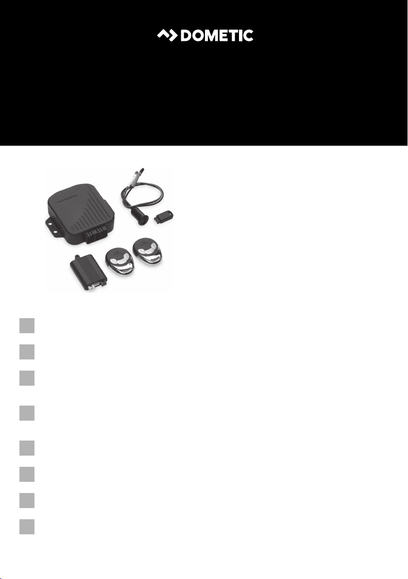
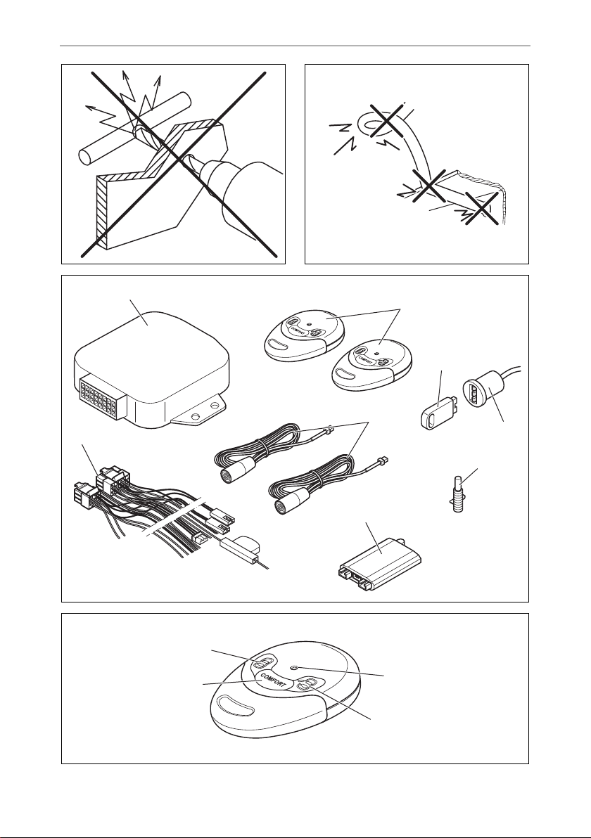
3 Scope of delivery . . . . . . . . . . . . . . . . . . . . . . . . . . . . . . . . . . . . . . . . . . . . . .18
4 Accessories . . . . . . . . . . . . . . . . . . . . . . . . . . . . . . . . . . . . . . . . . . . . . . . . . . .18
5 Intended use . . . . . . . . . . . . . . . . . . . . . . . . . . . . . . . . . . . . . . . . . . . . . . . . . .19
6 Technical description . . . . . . . . . . . . . . . . . . . . . . . . . . . . . . . . . . . . . . . . . . . 19
7 Installing MagicSafe . . . . . . . . . . . . . . . . . . . . . . . . . . . . . . . . . . . . . . . . . . . .21
8 Connecting the power to MagicSafe. . . . . . . . . . . . . . . . . . . . . . . . . . . . . . 25
9 Performing a functional test . . . . . . . . . . . . . . . . . . . . . . . . . . . . . . . . . . . . . 33
10 Programming MagicSafe . . . . . . . . . . . . . . . . . . . . . . . . . . . . . . . . . . . . . . . 36
11 Using MagicSafe . . . . . . . . . . . . . . . . . . . . . . . . . . . . . . . . . . . . . . . . . . . . . . 42
12 Troubleshooting . . . . . . . . . . . . . . . . . . . . . . . . . . . . . . . . . . . . . . . . . . . . . . 53
13 Care and cleaning. . . . . . . . . . . . . . . . . . . . . . . . . . . . . . . . . . . . . . . . . . . . . 54
14 Guarantee . . . . . . . . . . . . . . . . . . . . . . . . . . . . . . . . . . . . . . . . . . . . . . . . . . . 54
15 Disposal. . . . . . . . . . . . . . . . . . . . . . . . . . . . . . . . . . . . . . . . . . . . . . . . . . . . . 55
16 Technical data . . . . . . . . . . . . . . . . . . . . . . . . . . . . . . . . . . . . . . . . . . . . . . . . 55
14

EN
MS660 Explanation of symbols
1 Explanation of symbols
WARNING!
!
!
A
I
Safety instruction: Failure to observe this instruction can cause fatal or
serious injury.
CAUTION!
Safety instruction: Failure to observe this instruction can lead to injury.
NOTICE!
Failure to observe this instruction can cause material damage and impair
the function of the product.
NOTE
Supplementary information for operating the product.
2 Safety and installation instructions
The manufacturer accepts no liability for damage in the following cases:
• Faulty assembly or connection
• Damage to the product resulting from mechanical influences and excess voltage
• Alterations to the product without express permission from the manufacturer
• Use for purposes other than those described in the operating manual
Please observe the prescribed safety instructions and stipulations from the
vehicle manufacturer and service workshops.
WARNING!
Inadequate supply cable connections could result in short circuits, which
!
could have as a consequence that:
• Cable fires occur
• The airbag is triggered
• Electronic control devices are damaged
• Electric functions fail (indicators, brake light, horn, ignition, lights)
15

EN
Safety and installation instructions MS660
NOTICE!
To prevent the risk of short circuits, always disconnect the negative
A
Please observe the following instructions:
• When working on the following cables, only use insulated cable lugs, plugs and
• Use a crimping tool to connect the cables.
• When connecting to cable 31 (earth), screw the cable
terminal of the vehicle's electrical system before working on it.
If the vehicle has an additional battery, its negative terminal should also be
disconnected.
flat push-on receptacles:
– 30 (direct supply from positive battery terminal)
– 15 (connected positive terminal, behind the battery)
– 31 (return line from the battery, earth)
– L (indicator lights left)
– R (indicator lights right)
Do not use terminal strips.
– to the vehicle's earth bolt with a cable lug and a gear disc or
– to the sheet-metal bodywork with a cable lug and a self-tapping screw.
Ensure that there is a good earth connection.
If you disconnect the negative terminal of the battery, all data stored in the volatile
memories will be lost.
• The following data must be set again, depending on the vehicle equipment
options:
–Radio code
– Vehicle clock
–Timer
– On-board computer
– Seat position
You can find instructions for making these settings in the appropriate operating
instructions.
Observe the following installation instructions:
CAUTION!
!
• Secure the parts installed in the vehicle in such a way that they cannot
become loose under any circumstances (sudden braking, accidents)
and cause injuries to the occupants of the vehicle.
16

EN
MS660 Safety and installation instructions
• Secure any parts of the system covered by the bodywork in such a
manner that they cannot be come loose or damage other parts and
cables or impair vehicle functions (steering, pedals, etc).
• Always follow the safety instructions of the vehicle manufacturer.
Some work (e.g. on retention systems such as the AIRBAG etc.) may
only be performed by qualified specialists.
NOTICE!
A
Observe the following instructions when working with electrical parts:
A
• To prevent damage when drilling, make sure there is sufficient space
on the other side for the drill head to come out.
• Deburr all drill holes and treat them with a rust-protection agent.
NOTICE!
• When testing the voltage in electrical cables, only use a diode test
lamp or a voltmeter.
Test lamps with an illuminant take up voltages which are too high and
which can damage the vehicle's electronic system.
• When making electrical connections, ensure that:
– they are not kinked or twisted
– they do not rub on edges
– they are not laid in sharp edged ducts without protection.
• Insulate all connections.
• Secure the cables against mechanical wear with cable binders or insu-
lating tape, for example to existing cables.
17

EN
Scope of delivery MS660
3Scope of delivery
No. in
fig. 4, page 4
1 1 Control unit
2 2 Hand-held transmitter
3 1 Electronic key
4 1 Key holder and status LED
5 1 Bonnet contact switch
6 2 Ultrasonic sensors
7 1 Ultrasonic module
8 1 Connection cable
– 2 Warning sticker
– 1 Fastening and installation material
Quantity Designation
4Accessories
Available as accessory (not included in scope of delivery):
Designation Ref. no.
Additional siren MS-620SI
Additional siren with backup function MS-670SI
Radio hand-held transmitter 9101300009
Electronic key MS-670-EK
Radio motion detector 9101600003
Radio magnetic sensor 9101600002
Gas detector MSG150 9600000368
Servo motor ML-11
Inverse diode 1N4007 600535
18

EN
MS660 Intended use
5 Intended use
MagicSafe MS660 (ref. no. 9600000369) is an alarm system for installation in
passenger vehicles and caravans. It offers additional protection against the theft of
your vehicle and its contents.
6 Technical description
6.1 Function description
MagicSafe MS660 is an alarm system which features two ultrasonic sensors. It is
designed for vehicles with an on-board voltage of 12 volts. It is connected to the
vehicle horn or to an additional alarm siren.
The MagicSafe alarm system protects vehicles and their contents from theft.
An activated alarm system triggers an alarm as soon as:
• a door, the boot or the bonnet is opened,
• the ignition is turned on or
• a movement is detected by the sensors in the vehicle interior.
MagicSafe MS660 offers the following functions:
• Activation and deactivation via hand-held transmitter
In case the hand-held transmitter is lost or defective, the alarm system can be
deactivated using the electronic key or the personal identification number
(PIN code).
• Interior monitoring via ultrasonic sensors
• Programmable output for convenience functions
This allows you to e. g. close electric windows by activating the alarm system.
• Input for the connection of additional door contacts or a contact switch for the
bonnet or the boot.
• Gas detector MSG150 (accessory) connection
• Wireless learning of up to 15 additional radio sensors (accessory):
– Radio motion detector for monitoring the interior
– Radio magnetic sensors for monitoring e. g, roof boxes, caravan stowage
compartments or caravan windows
19

EN
Technical description MS660
6.2 Hand-held transmitter control elements
Hand transmitters have the following control elements:
fig. 5, page 4 Designation Function
1 “Lock” button Activates the alarm system
2 “COMFORT” button Activates the convenience output
3 “Unlock” button Deactivates the alarm system
4 LED indicator (blue)
6.3 MagicSafe operating modes
The alarm system has the following five operating modes:
• Stand-by
The alarm system is kept in stand-by as soon as it is installed and correctly
connected. However, it does not trigger the alarm when in stand-by.
• Activation time
The alarm system has an activation time of approx. 30 seconds.
The status LED on the key holder lights up as an visual indicator of the activation
time.
• Armed
If the alarm system is activated, it can trigger the alarm. This happens if someone
e. g. breaks the door open, opens the bonnet or enters the vehicle interior. If you
wish to drive off, you must first deactivate the alarm system. The system is then in
stand-by mode.
The status LED on the key holder lights up as an visual activation indicator.
• Alarm triggered
When an alarm has been triggered, this is indicated by visual and acoustic
signals.
• Workshop mode
You can set the alarm to workshop mode if, for example, the vehicle is to be
handed over for repairs or inspection (see chapter “Setting workshop mode” on
page 51). In workshop mode, all settings for the alarm system remain stored,
even if the battery is disconnected. The alarm system can be activated and
deactivated without the hand-held receiver or the electronic key.
The status LED on the key holder lights up every 15 seconds as a visual indicator
of the activation time.
20

EN
MS660 Installing MagicSafe
7 Installing MagicSafe
NOTE
I
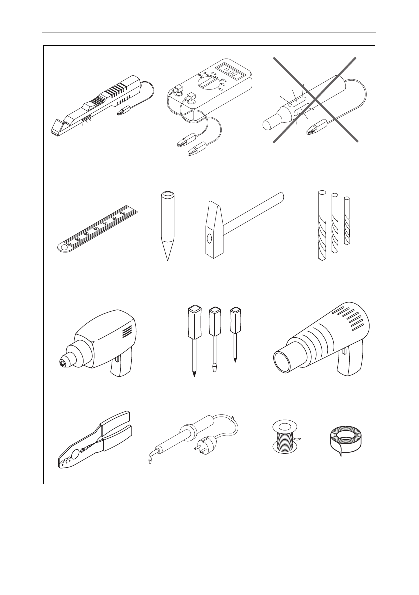
7.1 Tools required (fig. 1, page 3)
For installation and assembly you will need the following tools:
• Measuring ruler (4)
• Centre punch (5)
• Hammer (6)
• Drill head set (7)
• Drill (8)
• Screwdriver (9)
To establish and test the electrical connection, the following tools are required:
• Diode test lamp (1) or voltmeter (2)
• Hot air blower (10)
• Crimping tool (11)
• Soldering iron (optional) (12)
• Solder (optional) (13)
• Insulating tape (14)
• Heat shrinking sleeve
• Cable bushing sleeves (optional)
If you do not have sufficient technical knowledge for installing and
connecting the components in vehicles, you should have a specialist
install the alarm system in your vehicle.
To secure the cable you may require additional screws and cable binders.
21

EN
Installing MagicSafe MS660
7.2 Installing the controller
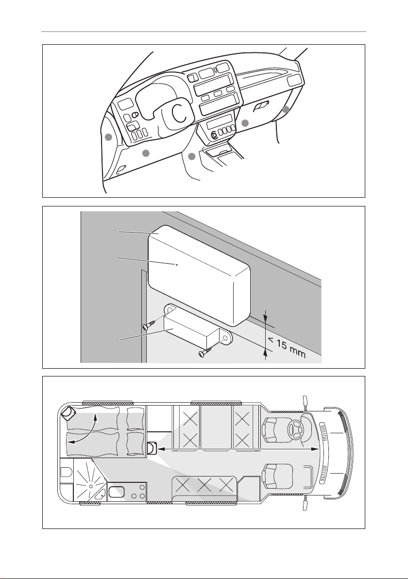
➤ Select a suitable installation location (fig. 6, page 5).
NOTE
I
➤ Install the control unit
– in the vehicle interior
– with the main connection cable facing downwards
– under the dashboard
– not in areas where strong electrical fields could cause interference,
– not directly next to ventilator nozzles.
➤ Where possible, use existing holes in the vehicle.
➤ Screw the control unit firmly to the vehicle with the screws supplied or use
double-sided adhesive tape.
When selecting the installation location, observe the following
instructions:
e. g. ignition cables or central control electronics,
7.3 Installing the ultrasonic module
➤ Select a suitable installation location close to the control unit.
➤ Screw the ultrasonic module firmly to the vehicle with the screws supplied or use
double-sided adhesive tape.
7.4 Installing the ultrasonic sensors
➤ Select a suitable installation location on the left and right A-pillars.
➤ Align the ultrasonic sensors with the middle of the rear window.
➤ Tightly fasten the ultrasonic sensors using the screws provided.
➤ Lay the cables down along the A pillar and over the dashboard to the ultrasonic
module.
22

EN
MS660 Installing MagicSafe
7.5 Installing the bonnet contact switch
This switch only needs to be installed if the vehicle does not already have one.
➤ Choose a suitable position in the engine compartment.
➤ Drill a hole with a diameter of 8 mm.
➤ During installation, make sure the distance to the closed bonnet is between
22 mm and 27 mm.
Use putty, for example, to check this distance.
You can further reduce the minimum distance by shortening the switch.
➤ Test the switch function after installation.
7.6 Installing the key holder
NOTE
I
➤ Select a suitable installation location near the dashboard.
➤ Drill a hole with a diameter of 15 mm.
➤ Push the sensors into the holders until they lock into place.
When selecting the installation location, observe the cable lengths.
7.7 Installing the alarm sirens (accessory)
Instead of the vehicle horn, you can connect an alarm siren (e. g. ref. no. MS-620SI
or MS-670SI).
NOTICE!
A
➤ Install the alarm sirens in the interior of the vehicle.
When installing, ensure that the installation location is not an area where
water might splash, and that it is not close to the exhaust system.
23

EN
Installing MagicSafe MS660
7.8 Installing additional radio sensors (accessory)
Installing the radio magnetic sensor (fig. 7, page 5)
The radio magnetic sensors allow you to lock e.g. roof boxes or caravan stowage
compartments or windows.
Observe the following installation instructions:
• Install the radio magnetic sensors in the interior of the vehicle.
• The interval between the magnet (3) and sensor (1) must not exceed 15 mm.
• Align the sensor so that the LED (2) points away from the magnet (3).
➤ Tightly fasten the magnet (3) to the door or to the window.
➤ Secure the sensor (1) to a fixed component (e. g. door or window frame) using
double-sided adhesive tape.
Do not cover the screws on the base with the adhesive tape.
➤ Test whether the interval is small enough:
When you open the doors, the LED (2) must light up once briefly.
Installing the radio motion sensor
When installing the motion sensor, observe the following instructions:
• Choose an installation location that allows the entire vehicle interior to be
monitored (fig. 8, page 5).
• The motion sensor can detect movements at a distance of maximum 12 m.
It cannot detect movements behind stationary objects such as partitions.
If appropriate, use several motion sensors.
• Try to avoid blind spots by positioning the sensors well.
• Do not install the motion sensor at a height of more than 2 m above the vehicle
floor.
• Do not install the motion sensor close to sources of heat, e. g. heaters,
or outlet nozzles for warm air.
➤ Press the housing of the motion sensor in slightly on both sides and remove it
from the rear wall (fig. 9, page 6)
➤ Screw the rear wall to a suitable installation location.
➤ Put the housing back onto the rear wall and click it into place.
24
EN
MS660 Connecting the power to MagicSafe
7.9 Installing the gas detector MSG150 (accessory)
➤ Install the gas detector as described in the relevant operating manual.
8 Connecting the power to MagicSafe
NOTICE!
A
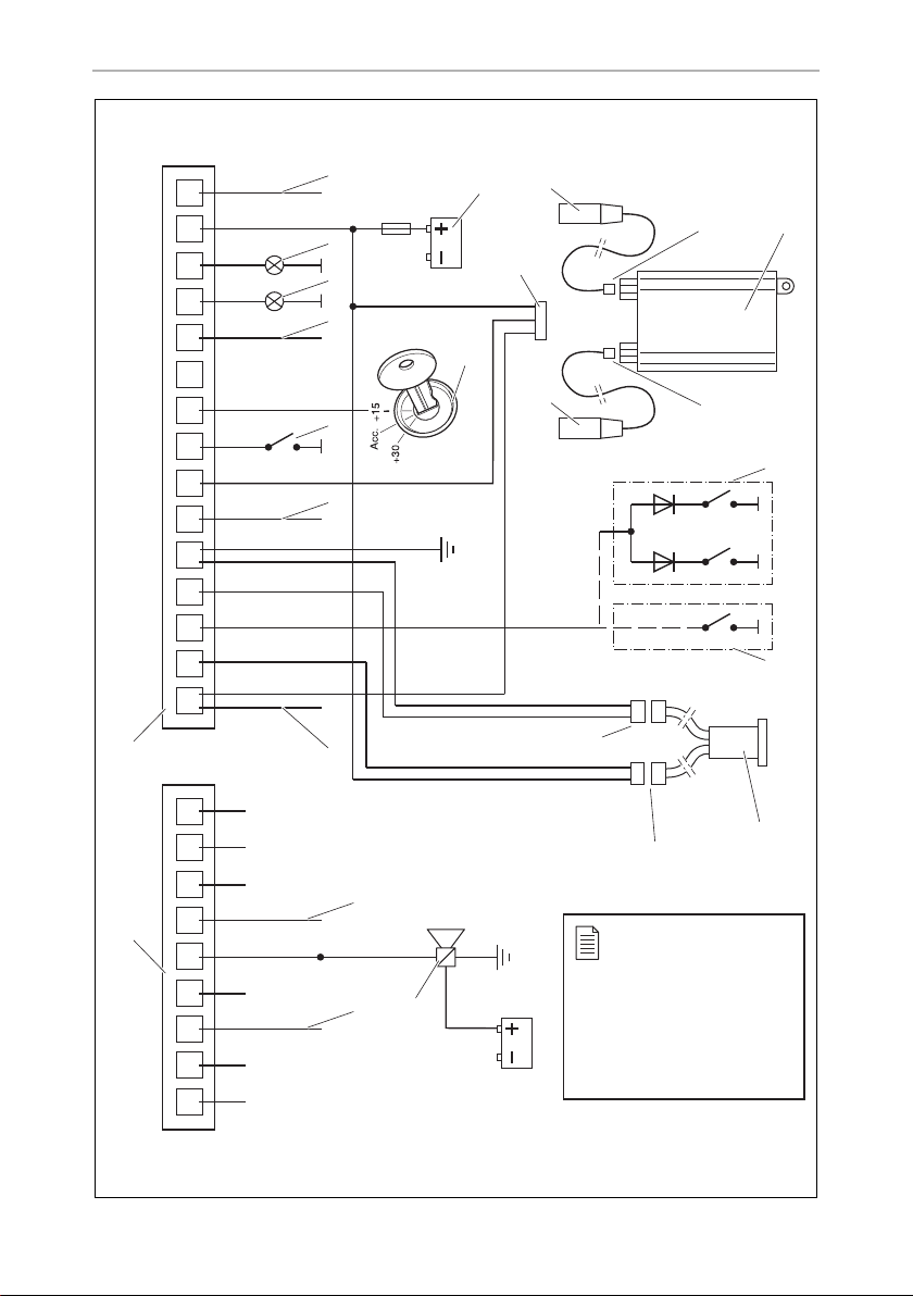
The complete circuit diagram for the alarm system can be found in fig. a, page 7.
No. Designation
For vehicles with catalysers, you must shut down the fuel pump while
making the electrical connections.
1 9-pin connection cable plug (CL)
2 15-pin connection cable plug (alarm)
3 Convenience output
4 Alarm siren with backup function (MS-670SI)
5 Earth-controlled input for optional accessory modules
6 Earth-controlled output for optional accessory modules
7 Start lock (e.g. for the fuel pump, for the starter) or horn/siren (MS-620SI)
8 Bonnet contact switch
9 Start lock (e.g. for the fuel pump, for the starter) or horn/siren (MS-620SI)
10, 11 Indicator
12 Antenna
13 Vehicle battery (starter battery)
14 Connected positive terminal (ignition, terminal 15)
25
EN
Connecting the power to MagicSafe MS660
No. Designation
15 3-pin plug for connection to the ultrasonic module
16 Ultrasonic sensors
17 Red plug connection ultrasonic sensor – ultrasonic module
18 Ultrasonic module
19 White plug connection ultrasonic sensor – ultrasonic module
20 Simultaneous connection to door contact switch and to the boot contact switch
(with inverse diodes only!)
21 Connection to door contact switches only (without inverse diodes!)
22 Red plug connection for key holder
23 White plug connection for key holder
24 Key holder incl. status LED
All plugs are coded so that you cannot connect them incorrectly.
8.1 Laying cables
When laying the cables, make sure:
• they are not kinked or twisted
• they do not rub on edges
• they are not laid in sharp-edged ducts without protection (fig. 3, page 4).
NOTICE!
A
➤ When laying cables in the engine compartment or boot, use existing openings
with rubber seals wherever possible.
Where there is no suitable opening, drill a hole with a diameter of
approximately 13 mm, and insert a cable duct sleeve.
I
Before drilling any holes, make sure that no electrical cables or other
parts of the vehicle can be damaged by drilling, sawing and filing
(fig. 2, page 4).
NOTE
Pull the socket connectors of the cables through the cable duct sleeve
before inserting the sleeve in the bodywork.
26

EN
MS660 Connecting the power to MagicSafe
➤ Lay the cables in the engine compartment or boot so that they cannot be
damaged under any circumstances (e. g. by flying stones).
➤ Insulate all unused cable ends.
8.2 Connecting the connection cable to the control unit
➤ Insert the plug of the connection cable into the corresponding connection on the
control unit
8.3 Connecting the connection cables of the 15-pole plug
Black (P1)
This cable is the antenna and does not have to be connected.
➤ Lay the antenna at an interval of at least 1 cm to metallic parts
Red (P2)
➤ Connect this cable to a cable with a permanent +12 volt charge
(terminal 30).
White/black (P3)
➤ Connect this cable to the left indicator cable of the vehicle.
Black/green (P4)
➤ Connect this cable to the right indicator cable of the vehicle.
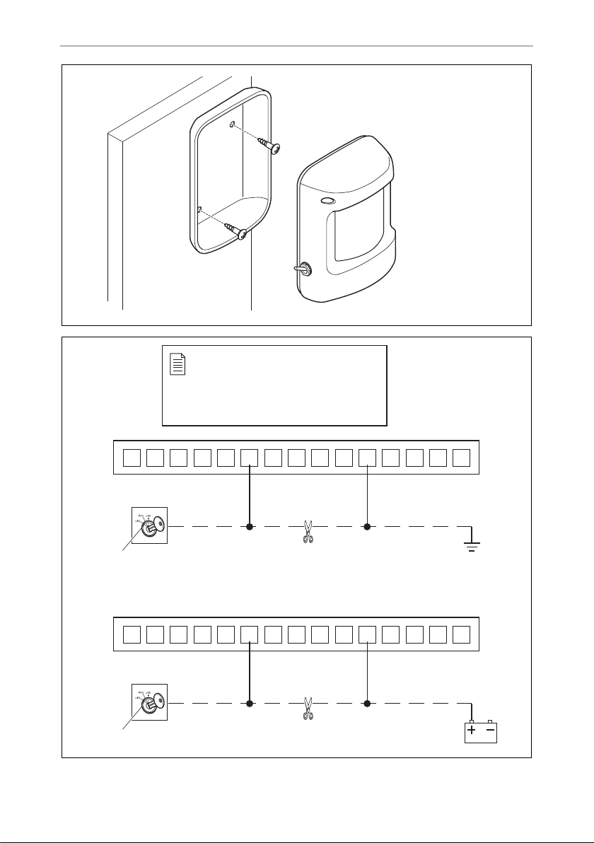
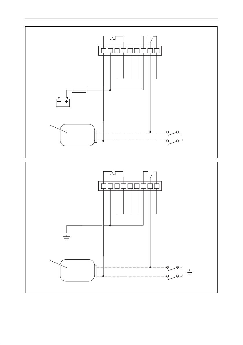
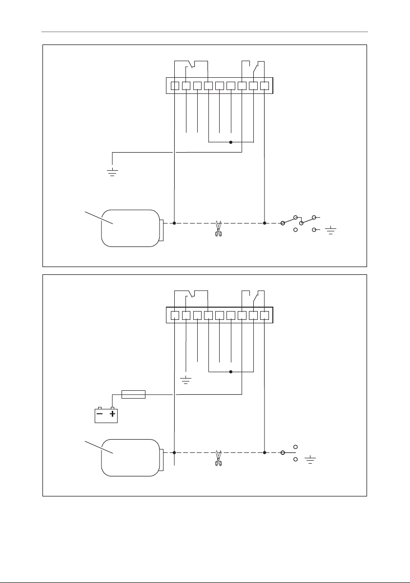
Green/yellow (P5) and green (P19),
factory-set as a starter circuit breaker
These cables can break any electrical circuit (e. g. fuel pump, starter etc.). The output
(green/yellow) can be charged with a maximum of 10 A.
➤ Disconnect the cable from the consumer (fig. 0 1, page 6) to earth (fig. 0 A,
page 6) or to the battery (fig. 0 B, page 6).
➤ Connect the green cable and the green/yellow cable in accordance with fig. 0,
page 6.
Alternatively, siren MS-620SI or the vehicle horn can be connected to the
green/yellow (P5) cable (see software functions no. 13 and no. 9).
27

EN
Connecting the power to MagicSafe MS660
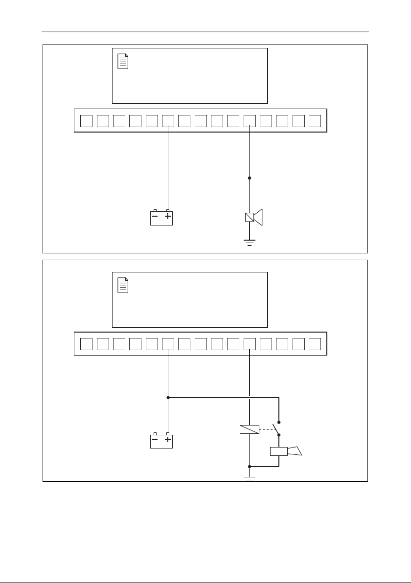
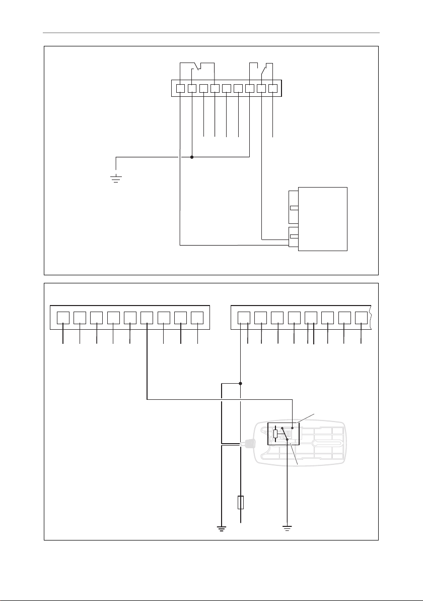
Connecting siren MS-620SI (accessory part)
➤ Connect the yellow cable and the green/yellow cable to siren MS-620SI in
accordance with fig. b, page 8.
➤ Program software function 13 to “Alarm output”.
➤ Program software function 9 to “Siren”.
Connecting the vehicle horn
➤ Connect the yellow cable and the green/yellow cable to the vehicle horn in
accordance with fig. c, page 8.
➤ Program software function 13 to “Alarm output”.
➤ Program software function 9 to “Horn”.
NOTICE!
A
Free slot (P6)
Not assigned.
Orange (P7)
When connecting the vehicle horn, an operating current relay with a
recovery diode must be used which has a rating of at least 20 A.
➤ Connect this cable to a connection which is switched by the ignition
(terminal 15).
Grey (P8)
➤ Connect this cable to the bonnet contact switch (fig. a 8, page 7).
The factory setting allows for a switch which is closed when the bonnet is open.
In case an original switch is to be used which is open when the bonnet is open,
this can be programmed in the control unit, see chapter “Function 15 (Bonnet
contact input)” on page 40.
Blue (P9)
This is the signal cable for the ultrasonic module. It ends in the 3-pole compact plug
(fig. a 15, page 7).
Green (P10)
See P5.
28

EN
MS660 Connecting the power to MagicSafe
Black (P11)
➤ Connect this cable to earth (terminal 31).
Red (P12)
Connects the key holder to the control unit.
Yel lo w ( P13)
NOTE
I
➤ Connect this cable to the door contact switch on the driver's door and,
if required, to the boot contact switch as well.
The factory setting allows for a switch which is closed when the door is open. If
the switch is open when the door is open, this can be programmed in the control
unit, see chapter “Function 16 (Door contact/boot input)” on page 40.
I
The boot contact switch only has to be connected if the lighting for the
passenger compartment (interior light) remains dark when the boot is
opened. In this case, use two diodes in the yellow cable as specified in
the wiring diagrams (fig. a 20, page 7).
NOTE
If it is not possible to connect the yellow cable to the door contact switch
in your vehicle, you have to connect the yellow cable to earth when
programming new hand-held transmitters, electronic keys or radio
sensors (see chapter “Learning the hand-held transmitter, electronic key
and radio sensors/reading the PIN code” on page 46).
Black (P14)
Connects the key holder to the control unit.
White + black (P15)
The white cable provides an additional earth-controlled output for optional
accessory modules.
The black cable is the earth cable for the ultrasonic module.
29

EN
Connecting the power to MagicSafe MS660
8.4 Connecting the connection cables of the 9-pole plug
(central locking)
MagicSafe features a universal connection for central locking to enable standard
central locking and engine-powered retrofitted central locking to be connected to
the system.
Connecting to the central locking system
➤ Determine the switching function of the original central locking system.
You will require the circuit diagram for the central locking system to do so. You
can obtain this from your vehicle dealership.
If no original circuit diagrams are available, you will need to gauge the function
of the control cables which run from the control unit of the central locking to the
vehicle doors.
NOTICE!
A
Connection to other cables than the control cables or the use of an incorrect circuit
plan can lead to a defect in the central locking system and the hand-held transmitter.
➤ Determine the activation time of the central locking system.
In some vehicles, for example Mercedes, an activation time of 0.7 sec. might not
be sufficient to completely activate the central locking system. If so, you will
need to set the control time using the software function 3 (Signal duration of the
door locking contacts) to 3 sec., see chapter “Software functions” on page 36.
Only connect MagicSafe using the control cables for the central locking
and not using other cables.
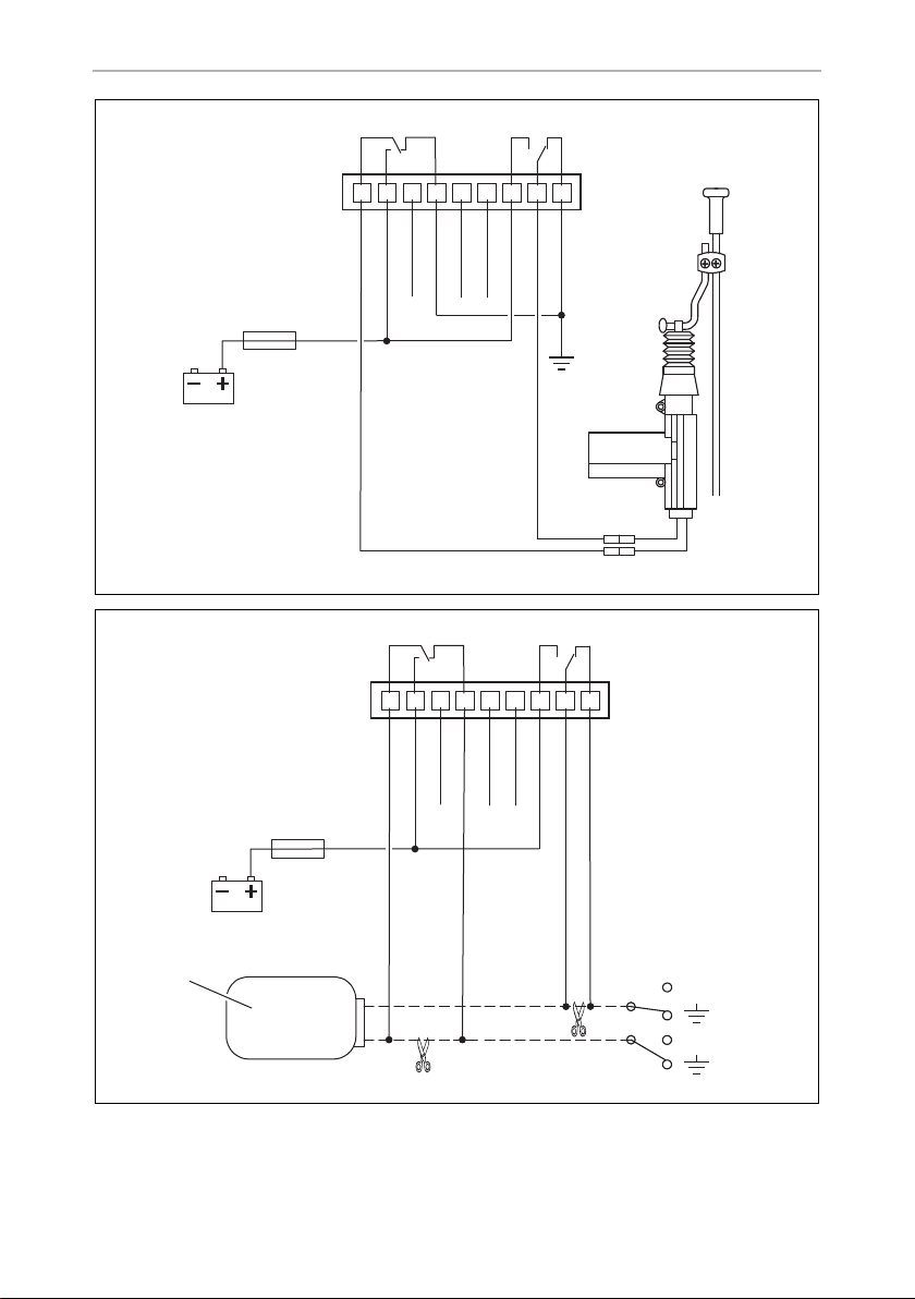
➤ Connect MagicSafe in accordance with the appropriate circuit diagram:
• Vehicles without a servo motor in the driver's door (driver's door cannot be
locked and unlocked from the passenger's do or ) or wi th p ress ure vacu um ce ntra l
locking without electrical control cable: fig. d, page 9
You will require an additional servo motor for this, type no. ML-11 for the driver's
door.
• Two cables switching from negative to +12 V: fig. e, page 9
• Two +12 V pulse control cables: fig. f, page 10
• Two negative pulse control cables: fig. g, page 10
• One open and negative pulse control cable: fig. h, page 11
• One +12 V and negative pulse control cable: fig. i, page 11
30

EN
MS660 Connecting the power to MagicSafe
• Connection to central locking system MagicLock ML44 and ML22: fig. j,
page 12
No. in fig. e
to fig. i
1 Control unit for the vehicle's own central locking system
➤ Insulate any unconnected cables.
Grey/white (P4)
This cable provides an additional earth controlled input for optional accessory
modules (e. g. wired magnetic contact switch).
Blue (P5)
The external backup siren MS-670SI (accessory) can be connected to this cable.
➤ Connect the blue cable to siren MS-670SI in accordance with fig. a, page 7.
Grey cable belonging to MS-670SI
If you have installed the bonnet contact switch belonging to MS660 (see chapter
“Installing the bonnet contact switch” on page 23), you have to connect it to the
grey cable belonging to siren MS-670SI.
➤ Connect one end of the grey cable to the cable of the bonnet contact switch.
➤ Connect the other end of the grey cable to the grey cable (P8) belonging to
MS660.
Designation
Green/red
This cable serves as a convenience output. The convenience output is earthed and
can be charged with up to 1 A.
NOTICE!
A
The convenience function allows you to e. g.:
• Close windows
• Close the sunroof
• Switch on dipped headlights
When connecting consumers with a power consumption of more than
1 A (e. g. dipped headlights), an additional operating current relay must
be used.
31

EN
Connecting the power to MagicSafe MS660
• Unlock the boot or fuel tank lid.
• Switch on the parking heating.
NOTE
I
You will require a convenience module or an operating current relay
with recovery diode, depending on your installation, for the convenience function.
8.5 Connecting the remaining connection cables (fig. a,
page 7)
Connecting the key holder
➤ Insert the red two-pin plug (22) of the connection cable into the red socket (22)
of the key holder.
➤ Insert the white two-pin plug (23) of the connection cable into the white
socket (23) of the key holder.
Connecting the ultrasonic module
➤ Insert the white three-pin plug (15) into the connection of the ultrasonic
module (18).
Connecting the ultrasonic senors
➤ Insert the red plug of the ultrasonic sensor cable (17) into the red connection of
the ultrasonic sensor (17).
➤ Insert the white plug of the ultrasonic sensor cable (19) into the white connection
of the ultrasonic sensor (19).
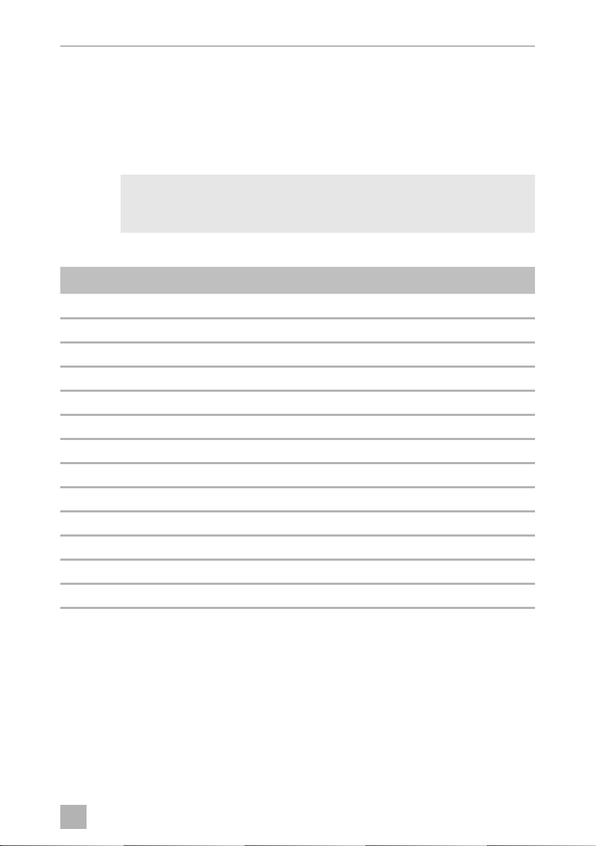
8.6 Connecting the gas detector MSG150 (accessory)
(fig. k, page 12)
➤ Disconnect the 12-volt plug from the gas detector cable.
➤ Remove around 10 cm of the outer insulation on the end of the cable.
➤ Connect the black cable to earth (terminal 31).
➤ Connect the yellow and the orange cable of the gas detector to the white cable
from MS660.
32

EN
MS660 Performing a functional test
➤ Connect the red cable to a cable to a permanent +12 volt charge (terminal +30).
The cable must be fused with at least a 1 A fuse.
If the gas detector is also to be switched to the alarm system as the main alarm,
connect both the relay contacts as follows:
➤ Connect the relay contact 1 (1) to earth (terminal 31).
➤ Connect the relay contact 2 (2) to the grey/white cable of MS660.
9 Performing a functional test
9.1 Testing the hand-held transmitter
➤ Test all of the switching functions with both hand-held transmitters.
If the system does not respond to a hand-held transmitter, program the hand-held
transmitter concerned (see chapter “Learning the hand-held transmitter, electronic
key and radio sensors/reading the PIN code” on page 46).
NOTE
I
The range of the hand-held transmitter can be restricted by solid metal
parts and strong electrical fields. It is usually between 10 m and 20 m.
9.2 Checking the central locking
If you activate the alarm system (see chapter “Activating MagicSafe” on page 43),
MagicSafe should lock the vehicle if central locking has been connected.
When you deactivate the alarm system (see chapter “Deactivating MagicSafe” on
page 44), MagicSafe should unlock the vehicle.
If you have programmed software function 11 (“Locking/unlocking with ignition”),
MagicSafe should lock the central locking approx. 5 sec. after the ignition is turned
on when the doors are closed. After the ignition is turned off, MagicSafe unlocks the
central locking again.
If the central locking is not working properly, proceed as follows:
➤ Check the electrical connection to the central locking.
➤ Check whether your vehicle supports software function 3 “Signal duration of the
door locking contacts” (see chapter “Programming” on page 41).
➤ Check which value has been set for software function 3.
33

EN
Performing a functional test MS660
9.3 Testing the sensitivity of the ultrasonic sensors
The sensitivity of the ultrasonic sensors can be adjusted on the ultrasonic module.
➤ Turn the setting screw on the underside of the ultrasonic module in the direction
of “+” to increase the sensitivity or ...
turn the setting screw of the ultrasonic module in the opposite direction to
reduce the sensitivity.
➤ To deactivate the ultrasonic module, turn the setting screw of the ultrasonic
sensor as far as it will go in the opposite direction to “+”.
NOTE
I
To find the right setting, proceed as follows:
➤ Deactivate the alarm system (see chapter “Deactivating MagicSafe” on page 44).
➤ Open the front side window about 20 cm.
➤ Activate the alarm system with the doors, bonnet and boot closed.
➤ Move an object into the vehicle interior from outside:
– If an alarm is triggered before you move the object into the vehicle, reduce
– If no alarm is triggered, increase the sensitivity.
If the ultrasonic sensors are set too sensitively, the alarm may be
triggered by passing vehicles. For this reason set the sensitivity carefully,
and not too high.
the sensitivity.
NOTE for convertibles and vehicles with folding tops
I
➤ Knock on the closed cover to check whether MagicSafe triggers the alarm when
the cover moves.
For vehicles with cloth or plastic roofs, the sensitivity of the ultrasonic
sensors must be reduced significantly or be disabled altogether.
34

EN
MS660 Performing a functional test
9.4 Testing other alarm inputs
➤ Test the function of the other alarm inputs in order by triggering an alarm.
➤ Count the number of flashes on the status LED afterwards.
If the number of flashes does not correspond to the specified value, you need to
check the connections and cables.
Number of flashes Alarm cause
0 (status LED off) No alarm triggered
1 Voltage drop sensor
2 Ultrasonic sensors (interior)
3 Door/boot contact switch
4 Bonnet contact switch
5 Ignition
7 Additional alarm input
8 Radio sensor
9 The battery in the hand-held transmitter is too weak
9.5 Testing optical and acoustic signals
➤ Trigger an alarm.
During the alarm, all indicators must be switched on and the vehicle horn or alarm
siren, as well as the status LED, must signal the alarm.
35

EN
Programming MagicSafe MS660
10 Programming MagicSafe
10.1 Software functions
MagicSafe has various software functions which you can alter in accordance with the
following table. Values marked in bold indicate the factory setting.
No. Software function “Lock” button “Unlock” button
1 Siren sound – confirmation tone
when activating and deactivating
2 Voltage drop sensor On Off
3 Signal duration of the door locking
contacts
4 Convenience locking function
(➔ no. 19)
5 Starter circuit breaker
(➔ no. 13)
6 Automatic reactivation On Off
7 Self-activation On Off
8 Circuit time for the convenience
output
(➔ no. 18)
9 Siren/vehicle horn selection
(➔ no. 13)
On Off
0.7 sec. 3sec.
On Off
On Off
20 sec. 1sec.
Siren Horn
36

EN
MS660 Programming MagicSafe
No. Software function “Lock” button “Unlock” button
10 Locking the central locking during
self-activation
11 Locking/unlocking with ignition On Off
12 Alarm detection for additional
sensors
13 Additional relay function Starter circuit
15 Bonnet contact input Switch open when
16 Door contact/boot input Switch open when
18 Car Finder/convenience function
on
19 Switch time for convenience locking
function
20 Deactivation of faulty door contacts On Off
24 Visual signals Hazard light Indicator
On Off
Additional sensor Additional sensor and
ultrasonic sensor
Alarm output
breaker
(➔ no. 5)
the bonnet is open
(12 volts)
the door is open
(12 volts)
Car Finder Convenience
25 sec. (auto) Manual
(➔ no. 9)
Switch closed
when the bonnet is
open (0 volts)
Switch closed
when the door is
open (0 volts)
output on
(➔ no. 8)
(➔ no. 4)
10.2 Description of the software functions
Function 1 (Siren sound – confirmation tone when activating and
deactivating)
This function enables a siren confirmation tone when the alarm system is activated
and deactivated.
NOTE
I
By activating the acoustic confirmation tone, the alarm system no longer
conforms to regulation 95/56/EC.
The operating approval for your vehicle expires within the scope of
validity of this directive!
37

EN
Programming MagicSafe MS660
Function 2 (Voltage drop sensor)
This function allows the voltage drop sensor to be activated or deactivated.
The sensor reacts to a vehicle battery load of at least 12 watts and triggers an alarm.
Function 3 (Signal duration of the door locking contacts)
In some vehicles, (for example Mercedes-Benz), an activation time of 0.7 sec. might
not be sufficient to completely activate the central locking system. In such cases, you
need to set the control time to 3 sec. using this software function.
Function 4 (Convenience locking function)
This activates or deactivates the convenience locking function, see chapter “Using
the convenience locking function” on page 49.
Function 5 (Starter circuit breaker)
This function allows you to activate or deactivate the starter circuit breaker.
The starter circuit breaker is activated:
• 30 sec. after the ignition was switched off (“Standby” mode, see chapter
“MagicSafe operating modes” on page 20)
• 60 sec. after the ignition was switched off using the remote control (“Standby”
mode, see chapter “MagicSafe operating modes” on page 20)
This function can only be used when function 13 is programmed to “Starter circuit
breaker”.
Function 6 (Automatic reactivation)
This function reactivates the alarm system if this was deactivated by mistake or
without being noticed. This occurs when the alarm system was deactivated and no
door was opened within approx. 40 sec.
Function 7 (Self-activation)
If the function is programmed to “On”, the alarm system activates itself automatically
when the ignition is switched off, approx. 10 sec. after the last door was closed.
Deactivation remains possible using the hand-held sensor.
Function 8 (Circuit time for the convenience output)
You can choose between 20 sec. (e. g. for shutting off the dipped headlights,
Coming Home function) or 1 sec. (e. g. for opening the tailgate). This function can
only be used when function 18 is programmed to “Convenience output on”.
38

EN
MS660 Programming MagicSafe
Function 9 (Siren/vehicle horn selection)
This function determines whether the vehicle horn or an external siren (e. g.
MS-620SI) is used. When set to “Siren”, the relay switches on to constant for 30 sec.
When set to “Horn”, the relay switches on and off every second for the duration of
30 sec. This function can only be used when function 13 is programmed to “Starter
circuit breaker”.
Function 10 (Locking the central locking during self-activation)
This determines whether the vehicle should be locked or not after self-activation of
the alarm system. This function can only be used when function 7 is programmed to
“On”.
Function 11 (Locking/unlocking with ignition)
When this function is activated, you can lock the vehicle when the ignition is
switched on by pressing the “Lock” button. In this case, the alarm system is not
activated.
The central locking unlocks the vehicle automatically when the ignition is switched
off.
Alternatively, the vehicle can be unlocked any time by pressing the “Unlock” button.
Function 12 (Alarm detection for additional sensors)
MagicSafe features an additional alarm output (grey/white cable). This function
allows you to determine whether this sensor alone can trigger the alarms or whether
it is only triggered in combination with the ultrasonic sensors.
Function 13 (Additional relay function)
This function is factory-set for use as a starter circuit breaker. This is already active in
“Standby” mode, not just in the event of an alarm.
This function can only be used when function 5 is programmed to “On”.
If function 13 is programmed to “Alarm output”, then this relay can, in the event of
an alarm, activate an additional warning device (e. g. a pager) or a further siren or
horn. In this case, the starter circuit breaker is not activated.
The siren or horn option can be determined by function 9.
39

EN
Programming MagicSafe MS660
Function 15 (Bonnet contact input)
This allows you to determine how the bonnet contact switch is connected.
The system is factory-set to a closed switch when the bonnet is open (voltage
0 volts). Should the switch used be open when the bonnet is open (voltage 12 volts),
function 15 must be programmed to “Switch opened when bonnet is open”.
Function 16 (Door contact/boot input)
This allows you to determine how the door contact switch and the boot contact
switch are connected.
The system is factory-set to a closed switch when a door is open/boot is open
(voltage 0 volts). Should the switch used be open when the bonnet is open/boot is
open (voltage 12 volts), function 16 must be programmed to “Switch opened when
door is open”.
NOTE
I
Function 18 (Car Finder/convenience function on)
This function allows you to determine whether the “COMFORT” button switches
additional convenience functions (e. g. Coming Home function) or whether it should
function as a Car Finder. In the second case, the indicators are activated for 10 min.
By pressing the “COMFORT” button again, the indicator will go out, the alarm
system remains activated.
If this function is programmed to “Car Finder”, function 8 (Convenience function)
cannot be used.
The boot contact switch only has to be connected if the lighting for the
passenger compartment (interior light) remains dark when the boot is
opened.
Function 19 (Switch time for convenience locking function)
In order to be able to use the convenience function, function 4 must be programmed
to “On”. In this case, the locking process remains activated for as long as the “Lock”
button is held down. On vehicles equipped with a factory-set convenience locking
module, the e. g. windows or the sliding sunroof can then be closed. Alternatively,
the locking process can be programmed to a fixed duration of 25 sec.
40

EN
MS660 Programming MagicSafe
Function 20 (Deactivation of faulty door contacts)
On vehicles without an interior light delay, this function must remain programmed to
“Off” (factory setting).
On vehicles with interior light delay, this function can be programmed to “On” so
that it detects doors left open by accident. As a result, the door can still be closed for
the first 15 sec. after activation of the alarm system to keep it in the alarm circuit. If the
door is closed after the 15 sec., it will no longer be monitored.
Function 24 (Visual signals)
A connection to the indicator cables has been provided at the factory. In the event of
an alarm, both alarm system indicator outputs generate a +12 volt interval signal.
If you wish to connect the optical signals via the hazard lights switch, you must
program this to “Hazard lights”. In this case, a short earth signal is switched from
both alarm system indicator outputs. After the alarm has finished (30 sec.), a further
earth signal is switched to deactivate the hazard light system.
10.3 Programming
Starting the programming mode
➤ Deactivate the alarm system using the remote control: Press the “Unlock” button.
➤ Open the driver's door and switch on the ignition.
➤ Press and hold the “Unlock” button and switch the ignition off.
➤ Release the “Unlock” button.
✓ The status LED lights up. You have now accessed the program menu.
NOTE
I
If 30 sec. elapse without a button being pressed, the program menu will
be quit automatically.
41

EN
Using MagicSafe MS660
Programming functions
The functions are programmed by pressing the button “Lock” or “Unlock”
repeatedly in accordance with the number of the function, see list, page 36.
Example: You wish to activate the convenience locking function. This is function 4.
Press the “Unlock” button 4 times to activate.
The status LED goes out briefly each time the button is pressed to confirm the
selection. To confirm the programming step, the status LED goes out for 2 sec.
The preferred value is saved.
➤ Perform all the required programming steps.
➤ To end programming, switch the ignition on.
11 Using MagicSafe
11.1 Function table
The following table lists all of the functions and how you can activate them.
Function Condition
Activating Ignition off ●
Deactivating Ignition off
Alarm system activated
Manual locking/unlocking of the
doors from the inside
Activating without
interior monitoring
Panic mode Ignition off
Convenience output Ignition off
Convenience output Ignition off
Ignition on ●
Ignition off ● ● (30 sec.)
Alarm system activated
Alarm system activated
Alarm system
deactivated
“Lock”
button
● ● (1 sec.)
42
“Unlock”
button
●
“COM-
FORT”
button
●
●

EN
MS660 Using MagicSafe
● Press the respective button
● ● (1 sec.) Press the button twice in a row within 1 sec.
● ● (30 sec.) Press the button twice in a row within 30 sec.
11.2 Activating MagicSafe
To activate the alarm system manually, proceed as follows:
➤ Close the doors of the vehicle.
➤ Press the “Lock” button on the hand-held transmitter for approx. 1 sec.
✓ The hazard lights flash twice.
✓ The alarm system is activated after approx. 30 sec. The status LED flashes in
confirmation.
On vehicles with central locking, the doors and boot are locked when the alarm
system is activated. If the vehicle is equipped with an original convenience function
(e. g. electric windows or electric sunroof), these will also be locked. You can control
the convenience function separately using the “COMFORT” button (see chapter
“Using the convenience locking function” on page 49).
If the alarm system is activated when a door, the bonnet or boot is open, the status
LED flashes every 3 sec. to indicate the problem.
If the door, bonnet or boot is closed within the next 15 sec., it will be reintegrated
into the alarm. If the door, bonnet or boot is closed after the 15 sec. have elapsed, it
will not be monitored.
Activating the alarm system so that the vehicle can remain occupied
You can set the alarm system so that the alarm system does not trigger an alarm when
a movement is registered in the interior of the vehicle, e. g. to leave a pet in the
vehicle.
Proceed as follows:
➤ Press the “Lock” button twice in a row within 30 sec.
✓ The hazard lights flash once.
43

EN
Using MagicSafe MS660
Reactivating the alarm system automatically
You can set MagicSafe so that the alarm system is reactivated automatically (software
function 7 “Self-activation”, factory setting: deactivated) if the vehicle is not used
within 30 sec. of deactivating the alarm system (opening a door or switching on the
ignition). The indicator flashes twice to indicate this.
The central locking remains unaffected. If you wish the doors to be locked by central
locking self-activation, activate software function 10 “Locking the central locking
during self-activation” (factory setting: deactivated).
11.3 Deactivating MagicSafe
To deactivate the alarm system manually, proceed as follows:
➤ Press the “Unlock” button on the hand-held transmitter for approx. 1 sec.
✓ The hazard lights flash once.
✓ If the alarm system is connected to the central locking, all doors and covers are
unlocked.
Deactivating MagicSafe without the hand-held transmitter
If you have misplaced the hand-held transmitter, the batteries are empty, or the
hand-held transmitter is damaged, you can deactivate the alarm system with the
electronic key.
➤ Open the door using the vehicle key.
✓ The alarm system triggers an alarm.
➤ Insert the electronic key in the socket.
✓ The alarm system is deactivated.
If the electronic key has also been lost, the alarm system can be deactivated using the
PIN code. To enter the 5-digit PIN code, proceed as follows:
➤ Open the driver's door using the ignition key, triggering an alarm by doing so.
➤ Wait 30 sec. until the alarm stops.
✓ The status LED lights up continuously.
➤ Switch the ignition on for 1 sec. and off again within 5 sec.
✓ The status LED starts flashing.
44

EN
MS660 Using MagicSafe
➤ Count the number of flashes until the number agrees with the first number of your
PIN code.
1 flash = number 1, 2 flashes = number 2, ..., 9 flashes = number 9, 10 flashes =
number 0.
➤ After the corresponding flashing signal, switch the ignition on for 1 sec. and off
again when the LED has gone out. This confirms the number.
✓ The status LED starts flashing again.
➤ Confirm all numbers in the PIN code in the same way.
Example: The system PIN code is “0 1 2 3 4”.
– Status LED flashes 10 x (= number 0), then switch the ignition on and off.
– Status LED flashes 1 x (= number 1), then switch the ignition on and off.
– Status LED flashes 2 x (= number 2), then switch the ignition on and off.
– Status LED flashes 3 x (= number 3), then switch the ignition on and off.
– Status LED flashes 4 x (= number 4), then switch the ignition on and off.
The PIN code has been entered.
✓ If you have entered the PIN code correctly, the alarm system will be in workshop
mode, see chapter “Setting workshop mode” on page 51.
If you have entered the PIN code incorrectly, the alarm will start again. In this
case, repeat the procedure from the start.
I
NOTE
Please note that every time a new hand-held transmitter or wireless radio
sensors (magnetic contact switch or motion detector) are programmed,
the PIN code is changed! It is therefore vital that the new PIN code is
noted in the manual for every learning process.
45

EN
Using MagicSafe MS660
11.4 Controlling the central locking with MagicSafe
NOTE
I
If your vehicle features central locking, you can lock or unlock doors automatically
from the inside. This function has been factory-set to deactivated. To activate it,
process as follows:
➤ Program software function 11 “Locking/unlocking with ignition” to “On”, see
chapter “Software functions” on page 36.
When the ignition is switched on, the central locking will now lock the vehicle when
the “Lock” button is pressed for 3 sec. The alarm system remains deactivated.
If you switch the ignition off, all doors will be unlocked without delay.
When locking using the hand-held transmitter, the ignition must be
switched on. Otherwise the alarm system will be activated as well.
11.5 Learning the hand-held transmitter, electronic key
and radio sensors/reading the PIN code
NOTE
I
• Learn all hand-held transmitters, electronic keys and radio sensors
(accessory) which you wish to use during the same programming
phase. This also applies for hand-held receivers which you have used
previously, or radio sensors which have already been paired!
• Learn the hand-held transmitter and the electronic key first, then – if
applicable – the radio motion detector (accessory) and then the
radio magnetic sensors (accessory).
Proceed as follows to learn hand-held transmitters, electronic keys as well as radio
sensors (e. g. radio motion detector, radio magnetic sensors – accessory):
Switching to learning mode
➤ Deactivate the alarm system by pressing the “Unlock” button.
➤ Open the driver's door.
➤ If you have not connected a door contact switch, you need to connect the yellow
cable belonging to MS660 to an earth point.
Maintain this connection throughout the entire programming process.
➤ Switch on the ignition.
➤ Press and hold down the “COMFORT” button.
46

EN
MS660 Using MagicSafe
➤ Switch the ignition off.
➤ Release the button.
✓ You are now in learning mode.
✓ The status LED flashes 10 times and then lights up continuously to confirm.
NOTE
I
Learning the hand-held transmitter
➤ Press the “COMFORT” button on the hand-held transmitter.
✓ The status LED goes out while the value is saved.
✓ If the stat us LED lights up continually again, then the hand-held receiver has been
learned and you can now proceed with the next one.
I
If you do not press a button within 10 seconds, you will exit the learning
mode.
NOTE
Only exit learning mode when you have learned all the hand-held
receivers, electronic keys and radio sensors you wish to use. Hand-held
receivers and radio sensors which you do not learn during this phase will
be automatically unpaired from the system. They can only be used once
they have been learned again.
Learning the electronic key
➤ Insert the electronic key into the key holder on the dashboard.
✓ The status LED goes out while the value is saved.
✓ If the stat us LED lights up continually again, then the hand-held receiver has been
learned and you can now proceed with the next one.
Learning the radio motion detector (accessory)
➤ Switch the motion detector on using the switch.
✓ The read status LED on the motion detector flashes.
✓ The motion detector has been learned.
47

EN
Using MagicSafe MS660
Learning the radio magnetic sensor (accessory)
➤ Disconnect the magnetic sensor contact (e. g. by opening a door secured by the
radio magnetic sensor).
✓ The read status LED on the magnetic sensor flashes once.
✓ The magnetic sensor has been learned.
Reading the PIN code
Once all hand-held transmitters and radio sensors (accessory) have been learned,
the status LED starts to flash after 10 sec. This sequence shows the new, updated
PIN code.
➤ Take a reading of the current PIN code.
Example:
Status LED flashes 10 x, then 2 sec. pause = number 0
Status LED flashes 1 x, then 2 sec. pause = number 1
Status LED flashes 2 x, then 2 sec. pause = number 2
Status LED flashes 3 x, then 2 sec. pause = number 3
Status LED flashes 4 x = number 4
The system PIN code is 0 1 2 3 4.
NOTE
I
Exiting learning mode
➤ Switch on the ignition.
➤ Switch the ignition off.
➤ If you connected the yellow cable belonging to MS660 to an earth point for the
programming process, you now need to remove this connection.
➤ Insulate and store the yellow cable.
Testing the hand-held transmitter
➤ Test the new hand-held transmitter.
If a hand-held receiver does not function, then they must all be learned again.
• Make a note of the PIN code and keep it in a safe place (e. g. at the
end of this manual, see page 56)!
• The PIN code is changed every time the hand-held transmitters are
learned.
48

EN
MS660 Using MagicSafe
11.6 Using the convenience locking function
If the vehicle has been equipped with a convenience module and software
function 4 “Convenience locking function” is activated, you can use the hand-held
transmitter to, e. g.:
• Close windows
• Close the sunroof
• Lock the boot or fuel tank lid
• Switch on dipped headlights
• Switch on the parking heating
To do this, proceed as follows:
➤ Press and hold the “Lock” button until e. g. the vehicle windows have closed
completely.
NOTE
I
Alternatively, you can program the control to a fixed duration of 25 sec.
(software function 19, see chapter “Programming MagicSafe” on
page 36).
11.7 Displaying the cause of the alarm
MagicSafe stores triggered alarms. The memory can display the last five alarm
situations.
If an alarm was triggered, this is indicated by a short flashing of the indicator (0.5 sec.)
when the vehicle is unlocked.
This is how to display the cause of the alarm:
➤ Deactivate the alarm system by pressing the “Unlock” button.
➤ Press the “Lock” and “Unlock” buttons simultaneously.
✓ The status LED shows the last five saved alarm causes in the form of flashing
signals, in accordance with the following list:
49

EN
Using MagicSafe MS660
Number of
flashes
1 Voltage drop sensor
2 Ultrasonic sensors (interior)
3 Door/boot contact switch
4 Bonnet contact switch
5 Ignition
7 Additional alarm input
8 Radio sensor
9 The battery in the hand-held transmitter is too weak
Cause of the alarm
11.8 Using the self-activation function
Self-activation (factory setting: deactivated) refers to the automatic arming of the
alarm system after leaving the vehicle. The ignition must be switched off for this and
the doors must be closed.
To set up self-activation, proceed as follows:
➤ Program software function 7 “Self-activation” to “On”.
✓ The alarm system activates itself 10 sec. after the ignition was switched off and a
door was opened and closed again.
I
50
NOTE
If you have set the system to self-activate, the central locking does not
lock the doors, to prevent you locking yourself out of the car by accident.

EN
MS660 Using MagicSafe
11.9 Setting workshop mode
You can set the alarm to the so-called workshop mode if, for example, the vehicle is
to be handed over for inspection or repairs. In workshop mode, all settings for the
alarm system remain stored, even if the battery is disconnected.
To do this, proceed as follows:
➤ Deactivate the alarm system.
➤ Close all the doors.
➤ Switch on the ignition.
➤ Press the “Lock” button three times within 5 sec.
✓ Workshop mode is switched on.
✓ The indicators light up once to confirm.
Switching off workshop mode
➤ Press the “Lock” button.
✓ Workshop mode is switched off.
✓ The indicators light up once to confirm and the central locking opens.
11.10 Using the panic mode
The alarm system has a panic mode. You can trigger the alarm by hand-held
transmitter, for example, to scare off an assailant if you are attacked. For this function,
the ignition must be switched off and the alarm system in activated mode.
To activate the panic mode, proceed as follows:
➤ Press the “Lock” button briefly twice in a row.
✓ The vehicle horn or alarm siren is switched on.
✓ The hazard lights flash.
Switching off the panic mode
➤ Press the “Unlock” button on the hand-held transmitter.
✓ The panic mode is switched off.
51

EN
Using MagicSafe MS660
11.11 Replacing the batteries
Please observe the following instructions for batteries:
WARNING!
!
• Only use leak-proof batteries that are suitable for electronic devices.
• Never attempt to do the following with batteries:
– recharge them,
–open them or
– throw them in fires.
• Dispose of old batteries appropriately.
Changing the battery in the hand-held transmitter
If the hand-held transmitter's range is reduced noticeably or if the control LED flickers
during transmission, the battery needs to be replaced.
➤ Undo the screw on the bottom of the hand-held transmitter.
➤ Open the hand-held transmitter.
A
Keep the batteries out of reach of children.
NOTICE!
Ensure the polarity of the batteries is correct when inserting. The positive
pole is at the top.
➤ Change the battery (battery type CR 2032, 3 volts).
➤ Refit the lid on the hand-held transmitter and re-insert the screw.
Changing the battery in the radio motion detector (accessory)
➤ Press the housing of the motion detector in slightly on both sides and remove it.
➤ Change the battery (9 volt battery).
➤ Put the housing back onto the rear wall and click it into place.
52

EN
MS660 Troubleshooting
Changing the battery in the radio magnetic sensor (accessory)
➤ Take off the sensor.
➤ Undo both screws on the back of the sensor.
➤ Open the sensor.
NOTICE!
A
➤ Change the battery (battery type CR 2032, 3 volts).
➤ Refit the lid on the sensor and re-insert the screw.
➤ Reattach the sensor.
Ensure the polarity of the batteries is correct when inserting. The positive
pole is at the top.
12 Troubleshooting
The range of the hand-held transmitter is decreasing.
The batteries are flat.
You have lost the hand-held transmitter or it has been damaged.
➤ Deactivate the alarm system using the electronic key or the PIN code (see chapter
“Deactivating MagicSafe without the hand-held transmitter” on page 44).
The indicators flash only once within 2 sec. instead of twice when you
switch the alarm system on.
The alarm system is warning you that a door or the bonnet or boot is open.
➤ Deactivate the alarm system.
➤ Rectify the fault.
➤ Reactivate the alarm system.
53

EN
Care and cleaning MS660
The indicators flash only once briefly (0.5 sec.) instead of once for longer
when you switch the alarm system off.
The alarm system has triggered an alarm.
➤ Sort the alarm memory.
This indicates the sensor which has triggered the alarm (see corresponding table
in chapter “Displaying the cause of the alarm” on page 49).
You deactivated the alarm system a few minutes ago, but the alarm system
has switched itself back on again.
The alarm system has possibly detected that you have not entered the vehicle and
has therefore automatically switched itself on and locked all the doors if this function
has been programmed (software function 7 “Self-activation”).
➤ Open a door or the bonnet/boot open to avoid this.
13 Care and cleaning
NOTICE!
A
Do not use sharp or hard objects or cleaning agents for cleaning as these
may damage the product.
➤ Occasionally clean the product with a damp cloth.
14 Guarantee
The statutory warranty period applies. If the product is defective, please contact the
manufacturer's branch in your country (see the back of the instruction manual for the
addresses) or your retailer.
For repair and guarantee processing, please send the following items:
• Defect components
• A copy of the receipt with purchasing date
• A reason for the claim or description of the fault
54

EN
MS660 Disposal
15 Disposal
➤ Place the packaging material in the appropriate recycling waste bins wherever
possible.
If you wish to finally dispose of the product, ask your local recycling centre
or specialist dealer for details about how to do this in accordance with the
M
B
applicable disposal regulations.
Protect the environment!
Do not dispose of any batteries with general household waste.
Return defective or used batteries to your retailer or dispose of them at
collection points.
16 Technical data
NOTE
I
The alarm system has a low power consumption (< 20 mA). You can
leave your vehicle with the alarm system activated for several weeks
without discharging the vehicle battery.
Controller
Operating voltage: 12 Vg (9 – 15 Vg)
Current consumption: < 20 mA (activated)
< 7 mA (deactivated)
Operating temperature: –40 °C to + 85 °C
Dimensions (W x D x H): 105 x 100 x 25 mm
55

EN
Technical data MS660
A-00 0267
Hand-held transmitter
Frequency: 433.992 MHz
Coding: Changing code system
Operating voltage: 3 V
Range: Up to 20 m
Battery type: CR2032, 3 volts
Operating temperature: –40 °C to + 85 °C
Dimensions (W x D x H): 54 x 39 x 12 mm
Certifications
The device has e1 certification and R&TTE certification.
PIN code
Always make a note of the current PIN code!
PIN code PIN code
56

DE
MS660
Bitte lesen Sie diese Anleitung vor Einbau und Inbetriebnahme sorgfältig
durch und bewahren Sie sie auf. Geben Sie sie im Falle einer Weitergabe
des Produktes an den Nutzer weiter.
Inhaltsverzeichnis
1 Erklärung der Symbole . . . . . . . . . . . . . . . . . . . . . . . . . . . . . . . . . . . . . . . . . 58
2 Sicherheits- und Einbauhinweise . . . . . . . . . . . . . . . . . . . . . . . . . . . . . . . . . 58
3 Lieferumfang . . . . . . . . . . . . . . . . . . . . . . . . . . . . . . . . . . . . . . . . . . . . . . . . . .61
4 Zubehör. . . . . . . . . . . . . . . . . . . . . . . . . . . . . . . . . . . . . . . . . . . . . . . . . . . . . .61
5 Bestimmungsgemäßer Gebrauch . . . . . . . . . . . . . . . . . . . . . . . . . . . . . . . . 62
6 Technische Beschreibung . . . . . . . . . . . . . . . . . . . . . . . . . . . . . . . . . . . . . . 62
7 MagicSafe montieren . . . . . . . . . . . . . . . . . . . . . . . . . . . . . . . . . . . . . . . . . . 64
8 MagicSafe elektrisch anschließen . . . . . . . . . . . . . . . . . . . . . . . . . . . . . . . . 68
9 Funktion testen . . . . . . . . . . . . . . . . . . . . . . . . . . . . . . . . . . . . . . . . . . . . . . . 77
10 MagicSafe programmieren. . . . . . . . . . . . . . . . . . . . . . . . . . . . . . . . . . . . . . 80
11 MagicSafe verwenden . . . . . . . . . . . . . . . . . . . . . . . . . . . . . . . . . . . . . . . . . 87
12 Fehler suchen . . . . . . . . . . . . . . . . . . . . . . . . . . . . . . . . . . . . . . . . . . . . . . . . 99
13 Pflegen und reinigen. . . . . . . . . . . . . . . . . . . . . . . . . . . . . . . . . . . . . . . . . . .100
14 Gewährleistung. . . . . . . . . . . . . . . . . . . . . . . . . . . . . . . . . . . . . . . . . . . . . . .100
15 Entsorgen . . . . . . . . . . . . . . . . . . . . . . . . . . . . . . . . . . . . . . . . . . . . . . . . . . .100
16 Technische Daten . . . . . . . . . . . . . . . . . . . . . . . . . . . . . . . . . . . . . . . . . . . . . 101
57

DE
Erklärung der Symbole MS660
1 Erklärung der Symbole
WARNUNG!
!
!
A
I
Sicherheitshinweis: Nichtbeachtung kann zu Tod oder schwerer
Verletzung führen.
VORSICHT!
Sicherheitshinweis: Nichtbeachtung kann zu Verletzungen führen.
ACHTUNG!
Nichtbeachtung kann zu Materialschäden führen und die Funktion des
Produktes beeinträchtigen.
HINWEIS
Ergänzende Informationen zur Bedienung des Produktes.
2 Sicherheits- und Einbauhinweise
Der Hersteller übernimmt in folgenden Fällen keine Haftung für Schäden:
• Montage- oder Anschlussfehler
• Beschädigungen am Produkt durch mechanische Einflüsse und Über-
spannungen
• Veränderungen am Produkt ohne ausdrückliche Genehmigung vom Hersteller
• Verwendung für andere als die in der Anleitung beschriebenen Zwecke
Beachten Sie die vom Fahrzeughersteller und vom Kfz-Handwerk
vorgeschriebenen Sicherheitshinweise und Auflagen!
WARNUNG!
Unzureichende Leitungsverbindungen können zur Folge haben, dass
!
58
durch Kurzschluss
• Kabelbrände entstehen,
• der Airbag ausgelöst wird,
• elektronische Steuerungseinrichtungen beschädigt werden,
• elektrische Funktionen ausfallen (Blinker, Bremslicht, Hupe, Zündung,
Licht).

DE
MS660 Sicherheits- und Einbauhinweise
ACHTUNG!
Klemmen Sie wegen der Kurzschlussgefahr vor Arbeiten an der Fahrzeug-
A
Beachten Sie deshalb folgende Hinweise:
• Verwenden Sie bei Arbeiten an den folgenden Leitungen nur isolierte Kabel-
• Verwenden Sie eine Krimpzange zum Verbinden der Kabel.
• Schrauben Sie das Kabel bei Anschlüssen an Leitung 31 (Masse)
elektrik immer den Minuspol ab.
Bei Fahrzeugen mit Zusatzbatterie müssen Sie an dieser ebenfalls den
Minuspol abklemmen.
schuhe, Stecker und Flachsteckhülsen:
– 30 (Eingang von Batterie Plus direkt)
– 15 (Geschaltetes Plus, hinter Batterie)
– 31 (Rückleitung ab Batterie, Masse)
– L (Blinkerleuchten links)
– R (Blinkerleuchten rechts)
Verwenden Sie keine Lüsterklemmen.
– mit Kabelschuh und Zahnscheibe an eine fahrzeugeigene Masseschraube
oder
– mit Kabelschuh und Blechschraube an das Karosserieblech.
Achten Sie auf eine gute Masseübertragung!
Beim Abklemmen des Minuspols der Batterie verlieren alle flüchtigen Speicher der
Komfortelektronik ihre gespeicherten Daten.
• Folgende Daten müssen Sie je nach Fahrzeugausstattung neu einstellen:
–Radiocode
–Fahrzeuguhr
– Zeitschaltuhr
– Bordcomputer
– Sitzposition
Hinweise zur Einstellung finden Sie in der jeweiligen Bedienungsanleitung.
Beachten Sie folgende Hinweise bei der Montage:
VORSICHT!
!
• Befestigen Sie die im Fahrzeug montierten Teile so, dass sie sich unter
keinen Umständen (scharfes Abbremsen, Verkehrsunfall) lösen und zu
Verletzungen der Fahrzeuginsassen führen können.
59

DE
Sicherheits- und Einbauhinweise MS660
• Befestigen Sie verdeckt unter Verkleidungen anzubringende Teile des
Systems so, dass sie sich nicht lösen oder andere Teile und Leitungen
beschädigen und keine Fahrzeugfunktionen (Lenkung, Pedale usw.)
beeinträchtigen können.
• Beachten Sie immer die Sicherheitshinweise des Fahrzeugherstellers.
Einige Arbeiten (z. B. an Rückhaltesystemen wie Airbag usw.) dürfen
nur von geschultem Fachpersonal durchgeführt werden.
ACHTUNG!
A
Beachten Sie folgende Hinweise bei der Arbeit an elektrischen Teilen:
A
• Achten Sie beim Bohren auf ausreichenden Freiraum für den Bohrer-
austritt, um Schäden zu vermeiden.
• Entgraten Sie jede Bohrung und behandeln Sie diese mit Rostschutzmittel.
ACHTUNG!
• Benutzen Sie zum Prüfen der Spannung in elektrischen Leitungen nur
eine Diodenprüflampe oder ein Voltmeter.
Prüflampen mit einem Leuchtkörper nehmen zu hohe Ströme auf,
wodurch die Fahrzeugelektronik beschädigt werden kann.
• Beachten Sie beim Verlegen der elektrischen Anschlüsse, dass diese
– nicht geknickt oder verdreht werden,
– nicht an Kanten scheuern,
– nicht ohne Schutz durch scharfkantige Durchführungen verlegt
werden.
• Isolieren Sie alle Verbindungen und Anschlüsse.
• Sichern Sie die Kabel gegen mechanische Beanspruchung durch
Kabelbinder oder Isolierband, z. B. an vorhandenen Leitungen.
60

DE
MS660 Lieferumfang
3 Lieferumfang
Nr. in
Abb. 4, Seite 4
1 1 Steuergerät
22Handsender
3 1 Elektronischer Schlüssel
4 1 Schlüsselaufnahme und Status-LED
5 1 Motorhauben-Kontaktschalter
6 2 Ultraschallsensoren
7 1 Ultraschallmodul
8 1 Anschlusskabel
– 2 Warnaufkleber
– 1 Befestigungs- und Montagematerial
Menge Bezeichnung
4Zubehör
Als Zubehör erhältlich (nicht im Lieferumfang enthalten):
Bezeichnung Art.-Nr.
Zusatzsirene MS-620SI
Zusatzsirene mit Backup-Funktion MS-670SI
Funk-Handsender 9101300009
Elektronischer Schlüssel MS-670-EK
Funk-Bewegungsmelder 9101600003
Funk-Magnetsensor 9101600002
Gasmelder MSG150 9600000368
Stellmotor ML-11
Sperrdiode 1N4007 600535
61

DE
Bestimmungsgemäßer Gebrauch MS660
5 Bestimmungsgemäßer Gebrauch
MagicSafe MS660 (Art.-Nr. 9600000369) ist eine Alarmanlage zum Einbau in PKWs
und Wohnmobile. Sie dient zum zusätzlichen Schutz gegen Diebstahl des Fahrzeugs und seines Inhalts.
6 Technische Beschreibung
6.1 Funktionsbeschreibung
MagicSafe MS660 ist eine Alarmanlage, die über zwei Ultraschallsensoren verfügt.
Sie ist ausgelegt für Fahrzeuge mit einer Bordspannung von 12 V. Sie wird an die
Fahrzeughupe angeschlossen oder an eine zusätzliche Alarmsirene.
Die MagicSafe-Alarmanlage schützt Fahrzeuge und deren Inhalt vor Diebstahl. Bei
aktivierter Alarmanlage wird ein Alarm ausgelöst, sobald
• eine Tür, der Kofferraum oder die Motorhaube geöffnet werden,
• die Zündung eingeschaltet wird oder
• eine Bewegung von den Sensoren im Fahrzeuginnenraum gemeldet wird.
Diese Funktionen bietet Ihnen MagicSafe MS660:
• Aktivierung und Deaktivierung über Handsender
Für den Fall, dass der Handsender verloren geht oder defekt ist, kann die Alarm-
anlage über den elektronischen Schlüssel oder die persönliche
Identifikationsnummer (PIN-Code) deaktiviert werden.
• Innenraumüberwachung über Ultraschallsensoren
• Programmierbarer Ausgang für Komfortfunktionen
Damit können Sie z. B. über die Aktivierung der Alarmanlage elektrisch betätigte
Fenster schließen.
• Eingang zum Anschluss zusätzlicher Türkontakte oder eines Kontaktschalters für
die Motorhaube oder den Kofferraum
• Anschluss des Gasmelders MSG150 (Zubehör)
• Drahtloses Anlernen von bis zu 15 zusätzlichen Funk-Sensoren (Zubehör):
– Funk-Bewegungsmelder für die Raumüberwachung
– Funk-Magnetsensoren für die Überwachung von z. B. Dachboxen,
Wohnmobil-Staufächern oder Wohnmobilfenstern
62

DE
MS660 Technische Beschreibung
6.2 Bedienelemente Handsender
Die Handsender haben folgende Bedienelemente:
Abb. 5, Seite 4 Bezeichnung Funktion
1 Taste „Schließen“ Alarmanlage aktivieren
2 Taste „COMFORT“ Komfort-Ausgang aktivieren
3 Taste „Öffnen“ Alarmanlage deaktivieren
4 Kontroll-LED (blau)
6.3 Mögliche Betriebszustände von MagicSafe
Die Alarmanlage kennt folgende fünf Betriebszustände:
• betriebsbereit
Die Alarmanlage ist ständig betriebsbereit, sobald sie eingebaut und korrekt
angeschlossen ist. Sie löst in diesem Betriebszustand jedoch keinen Alarm aus.
• Einschaltzeit
Die Alarmanlage hat eine Einschaltzeit von ca. 30 s.
Als optische Anzeige für die Einschaltzeit leuchtet die Status-LED an der
Schlüsselaufnahme.
• aktiviert
Wenn die Alarmanlage aktiviert ist, kann sie einen Alarm auslösen. Dies ist der
Fall, wenn z. B. eine Tür aufgebrochen, die Motorhaube geöffnet oder in den
Fahrzeuginnenraum eingestiegen wird. Wenn Sie wieder losfahren möchten,
müssen Sie die Alarmanlage deaktivieren. Dann ist sie wieder im Betriebszustand
„betriebsbereit“.
Als optische Anzeige für die Aktivierung blinkt die Status-LED an der Schlüsselaufnahme.
• Alarm ausgelöst
Wenn ein Alarm ausgelöst wurde, wird dies durch optische und akustische
Signale angezeigt.
• Werkstattmodus
Sie können den sogenannten Werkstattmodus einstellen, z. B. um das Fahrzeug
zur Inspektion oder Reparatur zu geben (siehe Kapitel „Werkstattmodus einstellen“ auf Seite 96). Im Werkstattmodus bleiben alle gespeicherten Einstellungen
erhalten, auch wenn die Batterie abgeklemmt wird. Die Alarmanlage kann ohne
Handsender oder den elektronischen Schlüssel aktiviert und deaktiviert werden.
Als optische Anzeige für die Einschaltzeit leuchtet die Status-LED an der
Schlüsselaufnahme alle 15 Sekunden.
63

DE
MagicSafe montieren MS660
7 MagicSafe montieren
HINWEIS
I
7.1 Benötigtes Werkzeug (Abb. 1, Seite 3)
Für Einbau und Montage benötigen Sie folgende Werkzeuge:
• Maßstab (4)
• Körner (5)
• Hammer (6)
• Satz Bohrer (7)
• Bohrmaschine (8)
• Schraubendreher (9)
Für den elektrischen Anschluss und seine Überprüfung benötigen Sie folgende
Hilfsmittel:
• Diodenprüflampe (1) oder Voltmeter (2)
• Heißluftföhn (10)
• Krimpzange (11)
• Ggf. Lötkolben (12)
• Ggf. Lötzinn (13)
• Isolierband (14)
• Wärmeschrumpfschlauch
• Ggf. Kabeldurchführungstüllen
Wenn Sie nicht über ausreichende technische Kenntnisse für das
Einbauen und Anschließen von Komponenten in Fahrzeugen verfügen,
sollten Sie sich die Alarmanlage von einem Fachmann ins Fahrzeug
einbauen lassen.
Zur Befestigung der Kabel benötigen Sie ggf. noch weitere Schrauben und
Kabelbinder.
64

DE
MS660 MagicSafe montieren
7.2 Steuergerät montieren
➤ Wählen Sie einen geeigneten Montageort (Abb. 6, Seite 5).
HINWEIS
I
➤ Montieren Sie das Steuergerät
– im Fahrgastinnenraum,
– mit dem Hauptanschlusskabel nach unten,
– unter dem Armaturenbrett,
– nicht im Einflussbereich starker elektrischer Felder, z. B. Zündleitungen oder
– nicht direkt an Luftaustrittsdüsen.
➤ Nutzen Sie möglichst vorhandene Bohrungen im Fahrzeug.
➤ Schrauben Sie das Steuergerät mit den beiliegenden Schrauben fest oder
verwenden Sie doppelseitiges Klebeband.
Beachten Sie bei der Wahl des Montageortes folgende Hinweise:
Zentralsteuerelektronik,
7.3 Ultraschallmodul montieren
➤ Wählen Sie einen geeigneten Montageort in der Nähe des Steuergerätes.
➤ Schrauben Sie das Ultraschallmodul mit den beiliegenden Schrauben fest oder
verwenden Sie doppelseitiges Klebeband.
7.4 Ultraschallsensoren montieren
➤ Wählen Sie jeweils einen geeigneten Montageort an der linken und rechten
A-Säule.
➤ Richten Sie die Ultraschallsensoren auf die Mitte der Heckscheibe aus.
➤ Schrauben Sie die Ultraschallsensoren mit den beiliegenden Schrauben fest.
➤ Verlegen Sie die Kabel an der A-Säule hinunter und über das Armaturenbrett zum
Ultraschallmodul.
65

DE
MagicSafe montieren MS660
7.5 Motorhauben-Kontaktschalter montieren
Diesen Schalter müssen Sie nur montieren, wenn das Fahrzeug nicht bereits über
einen solchen Schalter verfügt.
➤ Wählen Sie eine geeignete Stelle im Motorraum.
➤ Bohren Sie ein Loch mit einem Durchmesser von 8 mm.
➤ Achten Sie bei der Montage darauf, dass der Abstand zur geschlossenen Haube
minimal 22 mm und maximal 27 mm beträgt.
Ermitteln Sie diese Abstände z. B. mit Knetmasse.
Sie können den minimalen Abstand z. B. durch Kürzen des Schalters noch
verringern.
➤ Prüfen Sie nach dem Einbau die Schaltfunktion.
7.6 Schlüsselaufnahme montieren
HINWEIS
I
➤ Wählen Sie einen geeigneten Montageort im Bereich des Armaturenbretts.
➤ Bohren Sie ein Loch mit einem Durchmesser von 15 mm.
Beachten Sie bei der Wahl des Montageortes die Kabellängen.
➤ Stecken Sie die Schlüsselaufnahme in die Bohrung, bis sie einrastet.
7.7 Alarmsirene montieren (Zubehör)
Anstelle der Fahrzeughupe können Sie eine Alarmsirene (z. B. Art.-Nr. MS-620SI
oder MS-670SI) anschließen.
ACHTUNG!
A
➤ Montieren Sie die Alarmsirene im Motorraum.
66
Achten Sie bei der Montage darauf, dass der Montageort nicht im
Spritzwasserbereich und nicht in der Nähe der Auspuffanlage liegt.

DE
MS660 MagicSafe montieren
7.8 Zusätzliche Funk-Sensoren montieren (Zubehör)
Funk-Magnetsensor montieren (Abb. 7, Seite 5)
Mit den Funk-Magnetsensoren können Sie z. B. Dachboxen oder WohnmobilStaufächer oder -fenster sichern.
Beachten Sie folgende Hinweise bei der Montage:
• Montieren Sie den Funk-Magnetsensoren im Inneren des Fahrzeugs.
• Der Abstand zwischen Magneten (3) und Sensor (1) darf nicht mehr als 15 mm
betragen.
• Richten Sie den Sensor so aus, das die LED (2) vom Magneten (3) weg weist.
➤ Schrauben Sie den Magneten (3) an der Tür oder am Fenster fest.
➤ Fixieren Sie den Sensor (1) mit doppelseitigem Klebeband am feststehenden Teil
(z. B. Tür- oder Fensterrahmen).
Verdecken Sie dabei die Schrauben am Boden nicht mit dem Klebeband.
➤ Testen Sie, ob der Abstand klein genug ist:
Wenn Sie die Türe öffnen, muss die LED (2) einmal kurz aufleuchten.
Funk-Bewegungsmelder montieren
Beachten Sie folgende Hinweise bei der Montage des Bewegungsmelders:
• Wählen Sie den Montageort so, dass der Fahrzeuginnenraum komplett
überwacht wird (Abb. 8, Seite 5).
• Der Bewegungsmelder kann Bewegungen in einer Entfernung von maximal 12 m
erkennen. Er kann keine Bewegungen hinter festen Gegenständen wie z. B.
Zwischenwänden erkennen.
Verwenden Sie ggf. mehrere Bewegungsmelder.
• Versuchen Sie durch gute Positionierung, tote Winkel zu vermeiden.
• Montieren Sie den Bewegungsmelder nicht höher als 2 m über dem Boden des
Fahrzeugs.
• Montieren Sie den Bewegungsmelder nicht in der Nähe von Wärmequellen wie
z. B. Heizgeräten, oder Warmluftaustrittsdüsen.
➤ Drücken Sie das Gehäuse des Bewegungsmelders auf beiden Seiten leicht ein
und nehmen Sie es von der Rückwand ab (Abb. 9, Seite 6).
➤ Schrauben Sie die Rückwand an einen geeigneten Montageort.
➤ Setzen Sie das Gehäuse wieder auf die Rückwand und rasten Sie es ein.
67

DE
MagicSafe elektrisch anschließen MS 660
7.9 Gasmelder MSG150 montieren (Zubehör)
➤ Montieren Sie den Gasmelder wie in der zugehörigen Anleitung beschrieben.
8 MagicSafe elektrisch anschließen
ACHTUNG!
A
Den Gesamtschaltplan für die Alarmanlage finden Sie in Abb. a, Seite 7.
Nr. Bezeichnung
10, 11 Blinker
Bei Fahrzeugen mit Katalysator müssen Sie, während Sie die elektrischen Anschlüsse vornehmen, die Benzinpumpe außer Betrieb
nehmen.
1 9-poliger Stecker des Anschlusskabels (ZV)
2 15-poliger Stecker des Anschlusskabels (Alarm)
3 Komfortausgang
4 Alarmsirene mit Backup-Funktion (MS-670SI)
5 Massegesteuerter Eingang für optionale Zubehörmodule
6 Massegesteuerter Ausgang für optionale Zubehörmodule
7 Startsperre (z. B. zur Benzinpumpe, zum Anlasser) oder Hupe/Sirene
(MS-620SI)
8 Motorhauben-Kontaktschalter
9 Startsperre (z. B. zur Benzinpumpe, zum Anlasser) oder Hupe/Sirene
(MS-620SI)
12 Antenne
13 Fahrzeugbatterie (Starterbatterie)
14 Geschaltetes Plus (Zündung, Klemme 15)
68

DE
MS660 MagicSafe elektrisch anschließen
Nr. Bezeichnung
15
3-poliger Stecker zum Anschluss an das Ultraschallmodul
16
Ultraschallsensoren
17
Rote Steckverbindung Ultraschallsensor – Ultraschallmodul
18
Ultraschallmodul
19
Weiße Steckverbindung Ultraschallsensor – Ultraschallmodul
20
Gleichzeitiger Anschluss an Türkontaktschalter und an KofferraumKontaktschalter (nur mit Sperrdioden!)
21
Anschluss nur an Türkontaktschalter (ohne Sperrdiode!)
22
Rote Steckverbindung Schlüsselaufnahme
23
Weiße Steckverbindung Schlüsselaufnahme
24
Schlüsselaufnahme inkl. Status-LED
Alle Stecker sind codiert, so dass Sie diese nicht verkehrt anschließen können.
8.1 Kabel verlegen
Beachten Sie beim Verlegen der Kabel, dass diese
• nicht stark geknickt oder verdreht werden,
• nicht an Kanten scheuern,
• nicht ohne Schutz durch scharfkantige Durchführungen verlegt werden
(Abb. 3, Seite 4).
ACHTUNG!
A
➤ Verwenden Sie für die Verlegung der Kabel in den Motor- oder Kofferraum
möglichst vorhandene Öffnungen mit Gummistopfen.
Wenn keine Öffnungen vorhanden sind, fertigen Sie eine Bohrung von
ca. 13 mm Durchmesser an, und setzen Sie eine Kabeldurchführungstülle ein.
I
Bevor Sie irgendwelche Bohrungen vornehmen, stellen Sie sicher, dass
keine elektrischen Kabel oder andere Teile des Fahrzeuges durch
Bohren, Sägen und Feilen beschädigt werden (Abb. 2, Seite 4).
HINWEIS
Ziehen Sie die Steckbuchsen der Kabel durch die Kabeldurchführungstülle, bevor Sie die Tülle in die Karosserie einsetzen.
69

DE
MagicSafe elektrisch anschließen MS 660
➤ Verlegen Sie die Kabel so in den Motor- oder Kofferraum, dass sie unter keinen
Umständen beschädigt werden können (z. B. durch Steinschlag).
➤ Isolieren Sie alle nicht benutzten Kabelenden.
8.2 Anschlusskabel an Steuergerät anschließen
➤ Stecken Sie die Stecker des Anschlusskabels auf die entsprechenden Anschlüsse
am Steuergerät.
8.3 Anschlussleitungen des 15-poligen Steckers
anschließen
Schwarz (P1)
Diese Leitung ist die Antenne und muss nicht angeschlossen werden.
➤ Verlegen Sie die Antenne in einem Abstand von mindestens 1 cm zu metallischen
Teilen
Rot (P2)
➤ Schließen Sie diese Leitung an eine permanent +12 V führende Leitung an
(Klemme 30).
Schwarz/Weiß (P3)
➤ Schließen Sie diese Leitung an die linke Blinkerleitung des Fahrzeugs an.
Schwarz/Grün (P4)
➤ Schließen Sie diese Leitung an die rechte Blinkerleitung des Fahrzeugs an.
70

DE
MS660 MagicSafe elektrisch anschließen
Grün/Gelb (P5) und Grün (P10),
werksseitig als Startunterbrechung vorgesehen
Diese Leitungen dienen zur Unterbrechung eines beliebigen Stromkreises (z. B.
Benzinpumpe, Anlasser etc.). Der Ausgang (Grün/Gelb) darf mit maximal 10 A
belastet werden.
➤ Unterbrechen Sie die Leitung vom Verbraucher (Abb. 0 1, Seite 6) nach Masse
(Abb. 0 A, Seite 6) oder zur Batterie (Abb. 0 B, Seite 6).
➤ Schließen Sie die grüne und die grün/gelbe Leitung entsprechend Abb. 0,
Seite 6 an.
Alternativ kann an die Leitung Grün/Gelb (P5) die Sirene MS-620SI oder die
Fahrzeughupe angeschlossen werden (siehe Software-Funktion Nr. 13 und 9).
Sirene MS-620SI (Zubehör) anschließen
➤ Schließen Sie die gelbe und die grün/gelbe Leitung entsprechend Abb. b,
Seite 8 an die Sirene MS-620SI an.
➤ Programmieren Sie die Software-Funktion Nr. 13 auf „Alarmausgang“.
➤ Programmieren Sie die Software-Funktion Nr. 9 auf „Sirene“.
Fahrzeughupe anschließen
➤ Schließen Sie die gelbe und die grün/gelbe Leitung entsprechend Abb. c,
Seite 8 an die Fahrzeughupe an.
➤ Programmieren Sie die Software-Funktion Nr. 13 auf „Alarmausgang“.
➤ Programmieren Sie die Software-Funktion Nr. 9 auf „Hupe“.
ACHTUNG!
A
Freier Steckplatz (P6)
Nicht belegt.
Orange (P7)
➤ Schließen Sie diese Leitung an einen Anschluss an, der von der Zündung
geschaltet wird (Klemme 15).
Beim Anschluss der Fahrzeughupe muss ein Arbeitsstromrelais mit
Freilaufdiode mit einer Belastbarkeit von mindestens 20 A verwendet
werden.
71

DE
MagicSafe elektrisch anschließen MS 660
Grau (P8)
➤ Schließen Sie diese Leitung an den Motorhauben-Kontaktschalter (Abb. a 8,
Seite 7) an.
Werksseitig ist ein Schalter vorgesehen, der bei geöffneter Motorhaube
geschlossen ist.
Falls ein Originalschalter verwendet werden soll, der bei geöffneter Motorhaube geöffnet ist, kann dies im Steuergerät programmiert werden,
siehe Kapitel „Funktion 15 (Eingang Motorhaubenkontakt)“ auf Seite 84.
Blau (P9)
Dies ist die Signalleitung des Ultraschallmoduls. Sie endet in dem 3-poligen
Kompaktstecker (Abb. a 15, Seite 7).
Grün (P10)
Siehe P5.
Schwarz (P11)
➤ Schließen Sie diese Leitung an Masse an (Klemme 31).
Rot (P12)
Verbindet die Schlüsselaufnahme mit dem Steuergerät.
72

DE
MS660 MagicSafe elektrisch anschließen
Gelb (P13)
HINWEIS
I
➤ Schließen Sie diese Leitung an den Türkontaktschalter der Fahrertür und bei
Bedarf auch an den Kofferraum-Kontaktschalter an.
Werksseitig ist ein Schalter vorgesehen, der bei geöffneter Tür geschlossen ist.
Falls der Schalter bei geöffneter Tür geöffnet ist, kann dies im Steuergerät
programmiert werden, siehe Kapitel „Funktion 16 (Eingang Türkontakt/Kofferraum)“ auf Seite 84.
I
Der Kofferraum-Kontaktschalter muss nur angeschlossen werden, wenn
beim Öffnen des Kofferraums die Beleuchtung der Fahrgastzelle (Innenraumlicht) dunkel bleibt. Verwenden Sie in diesem Fall in der gelben
Leitung zwei Dioden wie im Schaltbild angegeben (Abb. a 20,
Seite 7).
HINWEIS
Wenn der Anschluss der gelben Leitung an den Türkontaktschalter bei
Ihrem Fahrzeug nicht möglich ist, müssen Sie beim Anlernen neuer
Handsender, elektronischer Schlüssel oder Funk-Sensoren die gelbe
Leitung an Masse legen (siehe Kapitel „Handsender, elektronische
Schlüssel und Funk-Sensoren anlernen / PIN-Code ablesen“ auf
Seite 91).
Schwarz (P14)
Verbindet die Schlüsselaufnahme mit dem Steuergerät.
Weiß + Schwarz (P15)
Die weiße Leitung bietet einen zusätzlichen massegesteuerten Ausgang für
optionale Zubehör-Module.
Die schwarze Leitung ist die Masseleitung des Ultraschallmoduls.
73

DE
MagicSafe elektrisch anschließen MS 660
8.4 Anschlussleitungen des 9-poligen Steckers
anschließen (Zentralverriegelung)
MagicSafe verfügt über Universalanschlüsse für Zentralverriegelungen, damit
serienmäßig eingebaute Zentralverriegelungen und motorgetriebene NachrüstZentralverriegelungen daran angeschlossen werden können.
An die Zentralverriegelung anschließen
➤ Ermitteln Sie die Schaltfunktion der originalen Zentralverriegelung.
Hierzu benötigen Sie den Schaltplan der Zentralverriegelung, den Sie bei Ihrem
Fahrzeughändler erhalten.
Wenn keine Originalschaltpläne zur Verfügung stehen, müssen Sie die Funktion
der Steuerleitungen, die von dem Steuergerät der Zentralverriegelung zu der
Fahrzeugtür verlaufen, ausmessen.
ACHTUNG!
A
Der Anschluss an andere Leitungen als die Steuerleitungen oder die Verwendung
eines falschen Schaltplans kann zum Defekt der Zentralverriegelung und des
Handsenders führen.
Schießen Sie MagicSafe nur über die Steuerleitungen der Zentralverriegelung und nicht über andere Leitungen an.
➤ Stellen Sie die Ansteuerungszeit der Zentralverriegelung fest.
Bei einigen Fahrzeugen, z. B. Mercedes, kann es sein, dass die Ansteuerungszeit von 0,7 s nicht ausreicht, um die Zentralverriegelung voll anzusteuern. In
solchen Fällen müssen Sie die Ansteuerungszeit durch die Software-Funktion 3
(Impulsdauer der Türschließkontakte) auf 3 s einstellen, siehe Kapitel „SoftwareFunktionen“ auf Seite 80.
➤ Schließen Sie MagicSafe gemäß passendem Schaltplan an:
• Fahrzeuge ohne Stellmotor in der Fahrertür (Fahrertür lässt sich nicht von der
Beifahrertür aus ver- und entriegeln) oder für Unterdruck-Zentralverriegelungen
ohne elektrische Steuerleitung: Abb. d, Seite 9
Hierfür benötigen Sie zusätzlich den Stellmotor Art.-Nr. ML-11 für die Fahrertür.
• Zwei von minus auf +12 V schaltende Leitungen: Abb. e, Seite 9
• Zwei +12 V impulssteuernde Leitungen: Abb. f, Seite 10
• Zwei minusimpulssteuernde Leitungen: Abb. g, Seite 10
• Eine offen und minusimpulssteuernde Leitung: Abb. h, Seite 11
• Eine +12 V und minusimpulssteuernde Leitung: Abb. i, Seite 11
74

DE
MS660 MagicSafe elektrisch anschließen
• Anschluss an Zentralverriegelung MagicLock ML44 und ML22: Abb. j,
Seite 12
Nr. in Abb. e bis
Abb. i
1 Steuergerät der fahrzeugeigenen Zentralverriegelung
Bezeichnung
➤ Isolieren Sie die nicht angeschlossenen Leitungen.
Grau/Weiß (P4)
Diese Leitung bietet einen zusätzlichen massegesteuerten Eingang für optionale
Zubehör-Module (z. B. verdrahtete Magnetkontaktschalter).
Blau (P5)
An diese Leitung können Sie die externe Backup-Sirene MS-670SI (Zubehör)
anschließen.
➤ Schließen Sie die blaue Leitung entsprechend Abb. a, Seite 7 an die Sirene
MS-670SI an.
Graue Leitung der MS-670SI
Wenn Sie den Motorhauben-Kontaktschalter der MS660 montiert haben (siehe
Kapitel „Motorhauben-Kontaktschalter montieren“ auf Seite 66), müssen Sie die
graue Leitung der Sirene MS-670SI mit diesem verbinden.
➤ Schließen Sie eine Seite der grauen Leitung an die Leitung des Motorhauben-
Kontaktschalters an.
➤ Schließen Sie die andere Seite der grauen Leitung an die graue Leitung (P8) der
MS660 an.
75

DE
MagicSafe elektrisch anschließen MS 660
Grün/Rot
Diese Leitung dient als Komfortausgang. Der Komfortausgang führt Masse und kann
mit bis zu 1 A belastet werden.
ACHTUNG!
A
Mit der Komfortfunktion können Sie z. B.:
• Fenster schließen
• Schiebedach schließen
• Abblendlicht einschalten
• Kofferraum oder Tankdeckel entriegeln
• Standheizung einschalten.
I
Beim Anschluss von Verbrauchern mit einer Stromaufnahme von mehr
als 1 A (z. B. Abblendlicht) muss ein zusätzliches Arbeitsstromrelais
verwendet werden.
HINWEIS
Für die Komfortfunktion benötigen Sie entsprechend Ihrer Installation
ein Komfortmodul oder ein Arbeitsstromrelais mit Freilaufdiode.
8.5 Restliche Anschlussleitungen anschließen (Abb. a,
Seite 7)
Schlüsselaufnahme anschließen
➤ Stecken Sie den roten zweipoligen Stecker (22) des Anschlusskabels auf die rote
Buchse (22) der Schlüsselaufnahme.
➤ Stecken Sie den weißen zweipoligen Stecker (23) des Anschlusskabels auf die
weiße Buchse (23) der Schlüsselaufnahme.
Ultraschallmodul anschließen
➤ Stecken Sie den weißen dreipoligen Stecker (15) auf den Anschluss des
Ultraschallmoduls (18).
Ultraschallsensoren anschließen
➤ Stecken Sie den roten Stecker des Ultraschallsensor-Kabels (17) auf den roten
Anschluss des Ultraschallsensors (17).
➤ Stecken Sie den weißen Stecker des Ultraschallsensor-Kabels (19) auf den
weißen Anschluss des Ultraschallsensors (19).
76

DE
MS660 Funktion testen
8.6 Gasmelder MSG150 (Zubehör) anschließen (Abb. k,
Seite 12)
➤ Trennen Sie den 12-V-Stecker vom Kabel des Gasmelders.
➤ Entfernen Sie etwa 10 cm der Außenisolierung am Ende des Kabels.
➤ Schließen Sie die schwarze Leitung an Masse an (Klemme 31).
➤ Verbinden Sie die gelbe und die orangefarbene Leitung des Gasmelders mit der
weißen Leitung von MS660.
➤ Schließen Sie die rote Leitung an eine permanent +12 V führende Leitung an
(Klemme +30). Die Leitung muss mit einer Sicherung von 1 A abgesichert sein.
Wenn der Gasmelder auch als Hauptalarm auf die Alarmanlage geschaltet werden
soll, schließen Sie die beiden Relaiskontakte wie folgt an:
➤ Schließen Sie den Relaiskontakt 1 (1) an Masse an (Klemme 31).
➤ Schließen Sie den Relaiskontakt 2 (2) an die grau/weisse Leitung von MS660 an.
9Funktion testen
9.1 Handsender testen
➤ Testen Sie alle Schaltfunktionen mit beiden Handsendern.
Wenn die Anlage auf einen Handsender nicht reagiert, lernen Sie den betroffenen
Handsender an (siehe Kapitel „Handsender, elektronische Schlüssel und
Funk-Sensoren anlernen / PIN-Code ablesen“ auf Seite 91).
HINWEIS
I
Die Reichweite der Handsender kann durch massive Metallteile und
starke elektrische Felder eingeschränkt werden. Sie liegt in der Regel
bei 10 m bis 20 m.
77

DE
Funktion testen MS660
9.2 Zentralverriegelung testen
Wenn Sie die Alarmanlage aktivieren (siehe Kapitel „MagicSafe aktivieren“ auf
Seite 88), muss MagicSafe bei angeschlossener Zentralverriegelung das Fahrzeug
verriegeln.
Wenn Sie die Alarmanlage deaktivieren (siehe Kapitel „MagicSafe deaktivieren“ auf
Seite 89), muss MagicSafe das Fahrzeug wieder entriegeln.
Wenn Sie die Software-Funktion 11 („Verriegeln/Entriegeln mit Zündung“) programmiert haben, muss MagicSafe ca. 5 s nach Einschalten der Zündung bei geschlossenen Türen die Zentalverriegelung verriegeln. Nach Ausschalten der Zündung öffnet
MagicSafe die Zentralverriegelung wieder.
Wenn die Zentralverriegelung nicht entsprechend arbeitet, gehen Sie wie folgt vor:
➤ Prüfen Sie den elektrischen Anschluss an die Zentralverriegelung.
➤ Prüfen Sie, ob Ihr Fahrzeug die Software-Funktion „3: Impulsdauer der Tür-
schließkontakte“ (siehe Kapitel „Programmieren“ auf Seite 86) unterstützt.
➤ Prüfen Sie, welcher Wert für die Software-Funktion 3 eingestellt ist.
9.3 Empfindlichkeit der Ultraschallsensoren testen
Die Empfindlichkeit der Ultraschallsensoren stellen Sie am Ultraschallmodul ein.
➤ Drehen Sie die Einstellschraube auf der Unterseite des Ultraschallmoduls in
Richtung „+“, um die Empfindlichkeit zu erhöhen oder …
drehen Sie die Einstellschraube des Ultraschallmoduls in die entgegengesetzte
Richtung, um die Empfindlichkeit zu verringern.
➤ Um das Ultraschallmodul zu deaktivieren, drehen Sie die Einstellschraube des
Ultraschallsensors bis zum Anschlag entgegen der Richtung „+“.
HINWEIS
I
Gehen Sie wie folgt vor, um die richtige Einstellung zu finden:
➤ Deaktivieren Sie die Alarmanlage (siehe Kapitel „MagicSafe deaktivieren“ auf
Seite 89).
➤ Öffnen Sie die vorderen Seitenfenster um etwa 20 cm.
➤ Aktivieren Sie die Alarmanlage bei geschlossenen Türen und Motor- und
Kofferraumhaube.
Wenn die Ultraschallsensoren zu empfindlich eingestellt sind, kann
durch vorbeifahrende Fahrzeuge ein Alarm ausgelöst werden. Stellen
Sie deshalb die Empfindlichkeit sorgfältig und nicht zu hoch ein.
78

DE
MS660 Funktion testen
➤ Bewegen Sie von außen ein Objekt ins Fahrzeuginnere:
– Wenn ein Alarm ausgelöst wird, bevor Sie das Objekt ins Fahrzeug bewegen,
verringern Sie die Empfindlichkeit.
– Wenn kein Alarm ausgelöst wird, erhöhen Sie die Empfindlichkeit.
HINWEIS für Cabrios und Fahrzeuge mit Faltdächern
I
➤ Prüfen Sie durch Klopftest auf das geschlossene Verdeck, ob MagicSafe bei
Bewegungen des Verdecks Alarm auslöst.
Bei Fahrzeugen mit Stoff- bzw. Kunststoffdächern muss die
Empfindlichkeit der Ultraschallsensoren stark reduziert werden oder
ganz außer Betrieb gesetzt werden.
9.4 Übrige Alarmeingänge testen
➤ Prüfen Sie der Reihe nach die Funktion der übrigen Alarmeingänge, indem Sie
jeweils einen Alarm auslösen.
➤ Zählen Sie danach die Blinksignale der Status-LED.
Wenn die Blinksignale nicht dem angegebenen Wert entsprechen, müssen Sie
die Anschlüsse und Kabelverbindungen prüfen.
Anzahl der Blink-
signale
0
(Status-LED aus)
1 Spannungsabfall-Sensor
2 Ultraschall-Sensoren (Innenraum)
3 Tür-/Kofferraumkontaktschalter
4 Motorhauben-Kontaktschalter
5Zündung
7 Zusätzlicher Alarmeingang
8Funk-Sensor
9 zu schwache Batterie im Handsender
Ursache des Alarms
kein Alarm ausgelöst
79

DE
MagicSafe programmieren MS660
9.5 Optische und akustische Signale testen
➤ Lösen Sie einen Alarm aus.
Während des Alarms müssen alle Blinkleuchten angesteuert werden und die
Fahrzeughupe oder Alarmsirene sowie die Status-LED den Alarm signalisieren.
10 MagicSafe programmieren
10.1 Software-Funktionen
MagicSafe bietet Ihnen verschiedene Software-Funktionen, die Sie entsprechend
der folgenden Tabelle ändern können.
Fett markierte Werte kennzeichnen die Werkseinstellung.
Nr. Software-Funktion Taste „Schließen“ Taste „Öffnen“
1 Sirenenton – Quittierton bei Aktivie-
rung und Deaktivierung
2 Spannungsabfall-Sensor Ein Aus
3 Impulsdauer der Türschließkontakte 0,7 s 3s
4 Komfort-Schließfunktion
(➔ Nr. 19)
5 Startunterbrechung
(➔ Nr. 13)
6 Automatische Reaktivierung Ein Aus
7 Selbstaktivierung Ein Aus
8 Schaltzeit des Komfortausgangs
(➔ Nr. 18)
9 Auswahl Sirene/Fahrzeughupe
(➔ Nr. 13)
Ein Aus
Ein Aus
Ein Aus
20 s 1s
Sirene Hupe
80

DE
MS660 MagicSafe programmieren
Nr. Software-Funktion Taste „Schließen“ Taste „Öffnen“
10 Verriegelung der Zentralverriege-
lung bei Selbstaktivierung
11 Verriegeln/Entriegeln mit Zündung Ein Aus
12 Alarmdetektion für zusätzliche
Sensoren
13 Funktion Zusatz-Relais Startunter-
15 Eingang Motorhaubenkontakt Schalter geöffnet bei
16 Eingang Türkontakt/Kofferraum Schalter geöffnet bei
18 Car Finder / Komfortfunktion ein Car Finder Komforta usgang
19 Schaltzeit für Komfort-Schließfunk-
tion
20 Deaktivierung fehlerhafter Türkon-
takte
24 Optische Signale Warnblinker Blinker
Ein Aus
Zusatzsensor Zusatzsensor und
Ultraschallsensor
Alarmausgang
brechung
(➔ Nr. 5)
geöffneter Haube
(12 V gemessen)
geöffneter Tür (12 V
gemessen)
25 s (auto) Manuell
Ein Aus
(➔ Nr. 9)
Schalter geschlossen bei geöffneter
Haube (0 V
gemessen)
Schalter geschlossen bei geöffneter
Tür (0 V gemessen)
ein
(➔ Nr. 8)
(➔ Nr. 4)
10.2 Erläuterung der Software-Funktionen
Funktion 1 (Sirenenton – Quittierton bei Aktivierung und Deaktivierung)
Diese Funktion ermöglicht einen Quittierton der Sirene beim Aktivieren und
Deaktivieren der Alarmanlage.
HINWEIS
I
Durch Aktivieren des Quittiertons als akustische Bestätigung entspricht
die Alarmanlage nicht mehr der Vorschrift 95/56/EC.
Die Betriebserlaubnis für Ihr Fahrzeug erlischt im Bereich der Gültigkeit
dieser Richtlinie!
81

DE
MagicSafe programmieren MS660
Funktion 2 (Spannungsabfall-Sensor)
Mit dieser Funktion kann der Spannungsabfall-Sensor aktiviert oder deaktiviert
werden. Der Sensor reagiert bei einer Belastung der Fahrzeugbatterie von
mindestens 12 Watt und löst einen Alarm aus.
Funktion 3 (Impulsdauer der Türschließkontakte)
Bei einigen Fahrzeugen (z. B. Mercedes-Benz) kann es sein, dass die
Ansteuerungszeit von 0,7 s nicht ausreicht, um die Zentralverriegelung voll
anzusteuern. In solchen Fällen müssen Sie die Ansteuerungszeit durch diese
Softwarefunktion auf 3 s einstellen.
Funktion 4 (Komfort-Schließfunktion)
Damit wird die Komfort-Schließfunktion aktiviert oder deaktiviert, siehe Kapitel
„Komfort-Schließfunktion nutzen“ auf Seite 94.
Funktion 5 (Startunterbrechung)
Mit dieser Funktion schalten Sie die Startunterbrechung ein oder aus.
Die Startunterbrechung wird aktiv:
• 30 s nachdem die Zündung ausgeschaltet wurde (Betriebszustand „betriebsbereit“, siehe Kapitel „Mögliche Betriebszustände von MagicSafe“ auf Seite 63)
• 60 s nachdem die Alarmanlage mit der Fernbedienung deaktiviert wurde
(Betriebszustand „betriebsbereit“, siehe Kapitel „Mögliche Betriebszustände
von MagicSafe“ auf Seite 63)
Diese Funktion kann nur genutzt werden, wenn Funktion 13 auf „Startunterbrechung“ programmiert ist.
Funktion 6 (Automatische Reaktivierung)
Diese Funktion reaktiviert die Alarmanlage, falls diese versehentlich oder unbemerkt
deaktiviert wurde. Dies geschieht, wenn die Alarmanlage deaktiviert und innerhalb
von ca. 40 s keine Tür geöffnet wurde.
Funktion 7 (Selbstaktivierung)
Wenn die Funktion auf „Ein“ programmiert ist, aktiviert sich die Alarmanlage bei
ausgeschalteter Zündung selbstständig ca. 10 s , nachdem die letzte Tür
geschlossen wurde. Die Deaktivierung ist weiterhin mit dem Handsender möglich.
82

DE
MS660 MagicSafe programmieren
Funktion 8 (Schaltzeit des Komfortausgangs)
Sie können wählen zwischen 20 s (z. B. für die Absteuerung des Abblendlichts,
Coming Home Funktion) oder 1 s (z. B. zum Öffnen der Heckklappe). Diese Funktion
kann nur genutzt werden, wenn Funktion 18 auf „Komfortausgang ein“ programmiert ist.
Funktion 9 (Auswahl Sirene/Fahrzeughupe)
Diese Funktion legt fest, ob die Fahrzeughupe oder eine externe Sirene (z. B.
MS-620SI) benutzt wird. Bei der Einstellung „Sirene“ schaltet das Relais konstant für
30 s ein. Bei der Einstellung „Hupe“ schaltet das Relais für die Dauer von 30 s im
Sekundentakt ein und aus. Diese Funktion kann nur genutzt werden, wenn
Funktion 13 nicht auf „Startunterbrechung“ programmiert ist.
Funktion 10 (Verriegelung der Zentralverriegelung bei Selbstaktivierung)
Damit wird festgelegt, ob bei einer Selbstaktivierung der Alarmanlage die Zentralverriegelung das Fahrzeug verriegeln soll oder nicht. Diese Funktion kann nur
genutzt werden, wenn Funktion 7 auf „Ein“ programmiert ist
Funktion 11 (Verriegeln/Entriegeln mit Zündung)
Wenn diese Funktion aktiviert ist, können Sie bei eingeschalteter Zündung das Fahrzeug durch Drücken auf die Taste „Schließen“ verriegeln. Die Alarmanlage wird in
diesem Fall nicht aktiviert.
Die Zentralverriegelung entriegelt das Fahrzeug automatisch, wenn die Zündung
ausgeschaltet wird.
Alternativ kann das Fahrzeug jederzeit durch Drücken der Taste „Öffnen“ entriegelt
werden.
Funktion 12 (Alarmdetektion für zusätzliche Sensoren)
MagicSafe verfügt über einen zusätzlichen Alarmeingang (grau/weiße Leitung). Mit
dieser Funktion legen Sie fest, ob allein dieser Sensor den Alarm auslösen kann oder
ob er nur in Verbindung mit den Ultraschallsensoren auslösen darf.
83

DE
MagicSafe programmieren MS660
Funktion 13 (Funktion Zusatz-Relais)
Werksseitig wird diese Funktion als Startunterbrechung genutzt. Diese wird bereits
im Betriebszustand „betriebsbereit“ aktiv, nicht erst im Alarmfall.
Die Funktion kann nur genutzt werden, wenn die Funktion 5 auf „Ein“ programmiert
ist.
Wenn die Funktion 13 auf „Alarmausgang“ programmiert wird, dann kann dieses
Relais im Alarmfall einen zusätzlichen Melder (z. B. einen Pager) oder eine weitere
Sirene oder Hupe aktivieren. In diesem Fall entfällt die Startunterbrechung.
Die Optionen Sirene oder Hupe kann durch Funktion 9 festgelegt werden.
Funktion 15 (Eingang Motorhaubenkontakt)
Damit legen Sie fest, wie der Motorhauben-Kontaktschalter beschaltet ist.
Werksseitig ist die Anlage für einen geschlossenen Schalter bei geöffneter Haube
eingestellt (Spannung 0 V). Sollte der verwendete Schalter bei geöffneter Haube
geöffnet sein (Spannung 12 V), muss die Funktion 15 auf „Schalter geöffnet bei
geöffneter Haube“ programmiert werden.
Funktion 16 (Eingang Türkontakt/Kofferraum)
Damit legen Sie fest, wie der Türkontaktschalter und der Kofferraum-Kontaktschalter
beschaltet sind.
Werksseitig ist die Anlage für einen geschlossenen Schalter bei geöffneter Tür /
geöffnetem Kofferraumdeckel eingestellt (Spannung 0 V). Sollte der verwendete
Schalter bei geöffneter Tür / geöffnetem Kofferraumdeckel geöffnet sein (Spannung
12 V), muss die Funktion 16 auf „Schalter geöffnet bei geöffneter Tür“ programmiert
werden.
HINWEIS
I
Funktion 18 (Car Finder / Komfortfunktion ein)
Mit dieser Funktion legen Sie fest, ob die Taste „COMFORT“ zusätzliche Komfortfunktionen (z. B. Coming Home Funktion) schaltet oder ob sie als Car Finder funktionieren soll. Im zweiten Fall werden die Blinker für 10 min aktiviert. Ein erneuter Druck
auf die Taste „COMFORT“ lässt die Blinker erlöschen, die Alarmanlage bleibt
aktiviert.
Wenn diese Funktion auf „Car Finder“ programmiert ist, kann Funktion 8 (Komfortfunktion) nicht genutzt werden.
Der Kofferraum-Kontaktschalter muss nur angeschlossen werden, wenn
beim Öffnen des Kofferraums die Beleuchtung der Fahrgastzelle (Innenraumlicht) dunkel bleibt.
84

DE
MS660 MagicSafe programmieren
Funktion 19 (Schaltzeit für Komfort-Schließfunktion)
Um die Komfort-Schließfunktion nutzen zu können, muss die Funktion 4 auf „Ein“
programmiert sein. In diesem Fall wird der Schließvorgang so lange aktiviert, wie die
Taste „Schließen“ gedrückt gehalten wird. Bei Fahrzeugen mit werksseitig ausgerüstetem Komfort-Schließmodul können dann z. B. die Fenster oder das Schiebedach geschlossen werden. Alternativ kann der Schließvorgang auf eine feste Dauer
von 25 s programmiert werden.
Funktion 20 (Deaktivierung fehlerhafter Türkontakte)
Bei Fahrzeugen ohne Innenraumlicht-Verzögerung muss diese Funktion auf „Aus“
programmiert bleiben (Werkseinstellung).
Bei Fahrzeugen mit Innenraumlicht-Verzögerung kann diese Funktion auf „Ein“
programmiert werden, um versehentlich offen stehende Türen zu erkennen. Dies hat
zur Folge, dass während der ersten 15 s nach Aktivierung der Alarmanlage die Tür
noch geschlossen werden kann, um diese im Alarmkreis beizubehalten. Wenn die
Tür nach den 15 s geschlossen wird, so wird sie nicht mehr überwacht.
Funktion 24 (Optische Signale)
Werksseitig ist der Anschluss an die Blinkerleitungen vorgesehen. Im Alarmfall
erzeugen dann beide Blinkerausgänge der Alarmanlage ein +12 V-Intervallsignal.
Falls Sie die optischen Signale über den Warnblinkschalter anschließen wollen,
müssen Sie diese Funktion auf „Warnblinker“ programmieren. In diesem Fall wird
aus beiden Blinkerausgängen der Alarmanlage ein kurzes Massesignal geschaltet.
Nach Beendigung des Alarms (30 s) wird ein weiteres Massesignal zum Abschalten
der Warnblinkanlage geschaltet.
85

DE
MagicSafe programmieren MS660
10.3 Programmieren
Programmier-Modus starten
➤ Deaktivieren Sie die Alarmanlage mit der Fernbedienung: Drücken Sie die Taste
„Öffnen“.
➤ Öffnen Sie die Fahrertür und schalten Sie die Zündung ein.
➤ Halten Sie die Taste „Öffnen“ gedrückt und schalten Sie die Zündung aus.
➤ Lassen Sie die Taste „Öffnen“ los.
✓ Die Status-LED leuchtet. Sie befinden sich nun im Programmiermodus.
HINWEIS
I
Funktion programmieren
Die Funktionen werden programmiert, indem Sie entsprechend der Nummer der
Funktion die Taste „Schließen“ oder „Öffnen“ wiederholt drücken, siehe Tabelle,
Seite 80.
Beispiel: Sie wollen die Komfort-Schließfunktion aktivieren. Dies ist die Funktion 4.
Drücken Sie zum Aktivieren 4x die Taste „Schließen“.
Nach 30 s ohne Tastendruck wird der Programmiermodus automatisch
beendet.
Zur Bestätigung jedes Tastendrucks erlischt die Status-LED kurz. Zur Bestätigung des
Programmierschrittes erlischt die Status-LED für 2 s.
Der gewünschte Wert wird gespeichert.
➤ Nehmen Sie alle gewünschten Programmierschritte vor.
➤ Schalten Sie zum Abschluss der Programmierung die Zündung ein.
86

DE
MS660 MagicSafe verwenden
11 MagicSafe verwenden
11.1 Funktionstabelle
In der folgenden Tabelle finden Sie eine Auflistung aller Funktionen und wie Sie
diese aktivieren.
Funktion Bedingung
Aktivieren Zündung aus ●
Deaktivieren Zündung aus
Alarmanlage aktiviert
Manuelles Verriegeln/Entriegeln
der Türen von innen
Aktivieren ohne
Innenraumüberwachung
Panik-Modus Zündung aus
Komfortausgang Zündung aus
Komfortausgang Zündung aus
● entsprechende Taste drücken
● ● (1 s) Taste zweimal hintereinander drücken innerhalb von 1 s
● ● (30 s) Taste zweimal hintereinander drücken innerhalb von 30 s
Zündung ein ●
Zündung aus ● ● (30 s)
Alarmanlage aktiviert
Alarmanlage aktiviert
Alarmanlage
deaktiviert
Ta s t e
„Schließen“
● ● (1 s)
Ta s t e
„Öffnen“
●
Ta s t e
„COMFORT“
●
●
87

DE
MagicSafe verwenden MS660
11.2 MagicSafe aktivieren
Gehen Sie wie folgt vor, um die Alarmanlage manuell zu aktivieren:
➤ Schließen Sie die Türen des Fahrzeugs.
➤ Drücken Sie die Taste „Schließen“ des Handsenders ca. 1 s lang.
✓ Die Warnblinkanlage blinkt 2x.
✓ Die Alarmanlage wird nach ca. 30 s aktiviert. Zur Bestätigung blinkt die
Status-LED.
Bei Fahrzeugen mit Zentralverriegelung werden bei Aktivierung der Alarmanlage
die Türen und der Kofferraum verriegelt. Wenn das Fahrzeug eine Original-Komfortfunktion besitzt (z. B. elektrische Fensterheber oder elektrisches Schiebedach),
werden auch diese verriegelt. Sie können diese Komfortfunktion mit der Taste
„COMFORT“ separat steuern (siehe Kapitel „Komfort-Schließfunktion nutzen“ auf
Seite 94).
Wenn die Alarmanlage bei geöffneter Tür, Motor- oder Kofferraumhaube aktiviert
wird, blinkt die Status-LED im 3 s-Takt, um die Störung anzuzeigen.
Wenn die Tür, Motor- oder Kofferraumhaube innerhalb der nächsten 15 s
geschlossen wird, so wird sie wieder in den Alarm einbezogen. Wird die Tür, Motoroder Kofferraumhaube nach den 15 s geschlossen, wird sie nicht überwacht.
Alarmanlage so aktivieren, dass das Fahrzeug besetzt bleiben kann
Sie können die Alarmanlage so einstellen, dass die Alarmanlage keinen Alarm
auslöst, wenn eine Bewegung im Innenraum des Fahrzeugs registriert wird, z. B.
um ein Haustier im Fahrzeug zu lassen.
Gehen Sie dazu wie folgt vor:
➤ Drücken Sie die Taste „Schließen“ innerhalb von 30 s zweimal hintereinander.
✓ Die Warnblinkanlage blinkt einmal.
88

DE
MS660 MagicSafe verwenden
Alarmanlage automatisch wieder aktivieren
Sie können MagicSafe so einstellen, dass die Alarmanlage automatisch wieder
aktiviert wird (Software-Funktion 7 „Selbstaktivierung“, werkseitig deaktiviert), wenn
nicht innerhalb von 30 s, nachdem Sie die Alarmanlage deaktiviert haben, das Fahrzeug benutzt wird (Tür öffnen oder Zündung einschalten). Dies wird durch zweimaliges Blinken der Blinker angezeigt.
Die Zentralverriegelung bleibt dabei unberücksichtigt. Wenn Sie möchten, dass
durch die Selbstaktivierung die Zentralverriegelung auch die Türen verriegelt
werden, aktivieren Sie die Software-Funktion 10 „Verriegelung der Zentralverriegelung bei Selbstaktivierung“ (werkseitig deaktiviert).
11.3 MagicSafe deaktivieren
Gehen Sie wie folgt vor, um die Alarmanlage zu deaktivieren:
➤ Drücken Sie die Taste „Öffnen“ des Handsenders etwa 1 s lang.
✓ Die Warnblinkanlage blinkt 1x.
✓ Falls Sie die Alarmanlage mit der Zentralverriegelung verbunden haben,
werden alle Türen entriegelt.
MagicSafe ohne Handsender deaktivieren
Falls Sie die Handsender verlegt haben, die Batterien leer sind oder die Handsender
beschädigt sind, können Sie die Alarmanlange mit dem elektronischen Schlüssel
deaktivieren.
➤ Schließen Sie die Tür mit dem Fahrzeugschlüssel auf.
✓ Die Alarmanlage löst einen Alarm aus.
➤ Stecken Sie den elektronischen Schlüssel in den Sockel.
✓ Die Alarmanlage wird deaktiviert.
Wenn auch der elektronische Schlüssel verloren ist, kann die Alarmanlage mit Hilfe
des PIN-Codes deaktiviert werden. Um den 5-stelligen PIN-Code einzugeben,
gehen Sie wie folgt vor:
➤ Öffnen Sie die Fahrertür mit dem Zündschlüssel und lösen hierdurch einen Alarm
aus.
➤ Warten Sie 30 s, bis der Alarm verstummt.
✓ Die Status-LED leuchtet konstant.
89

DE
MagicSafe verwenden MS660
➤ Schalten Sie innerhalb von 5 s die Zündung für 1 s ein und wieder aus.
✓ Die Status-LED beginnt zu blinken.
➤ Zählen Sie die Anzahl der Blinksignal, bis die Anzahl mit der ersten Ziffer Ihres
PIN-Codes übereinstimmt.
1x blinken = Ziffer 1, 2x blinken = Ziffer 2, ..., 9x blinken = Ziffer 9,
10x blinken = Ziffer 0.
➤ Schalten Sie nach dem entsprechenden Blinkzeichen, wenn die LED erloschen
ist, die Zündung für 1 s ein und wieder aus. Dadurch bestätigen Sie die Ziffer.
✓ Die Status-LED beginnt erneut zu blinken.
➤ Bestätigen Sie in gleicher Weise sämtliche Ziffern des PIN-Codes.
Beispiel: Der PIN-Code der Anlage lautet „0 1 2 3 4“.
– Status-LED blinkt 10x (= Ziffer 0), danach Zündung ein- und wieder
ausschalten.
– Status-LED blinkt 1x (= Ziffer 1), danach Zündung ein- und wieder
ausschalten.
– Status-LED blinkt 2x (= Ziffer 2), danach Zündung ein- und wieder
ausschalten.
– Status-LED blinkt 3x (= Ziffer 3), danach Zündung ein- und wieder
ausschalten.
– Status-LED blinkt 4x (= Ziffer 4), danach Zündung ein- und wieder
ausschalten.
Der PIN-Code ist eingegeben.
✓ Wenn Sie den PIN-Code richtig eingegeben haben, befindet sich die Alarm-
anlage im Werkstattmodus, siehe Kapitel „Werkstattmodus einstellen“ auf
Seite 96.
Wenn Sie den PIN-Code falsch eingegeben haben, beginnt der Alarm erneut.
Wiederholen Sie in diesem Fall die Prozedur von vorne.
HINWEIS
I
Bitte beachten Sie, dass bei jedem Anlernen neuer Handsender oder
drahtloser Funk-Sensoren (Magnetkontaktschalter oder Bewegungsmelder) der PIN-Code geändert wird! Daher ist es sehr wichtig, bei
jedem Anlernvorgang den neuen PIN-Code in der Anleitung zu
notieren.
90

DE
MS660 MagicSafe verwenden
11.4 Zentralverriegelung mit MagicSafe schalten
HINWEIS
I
Wenn Ihr Fahrzeug über eine Zentralverriegelung verfügt, können Sie die Türen von
innen automatisch verriegeln oder entriegeln. Diese Funktion ist werksseitig ausgeschaltet. Um sie zu aktivieren, gehen Sie wie folgt vor:
➤ Programmieren Sie die Software-Funktion 11 „Verriegeln/Entriegeln mit
Zündung“ auf „Ein“, siehe Kapitel „Software-Funktionen“ auf Seite 80.
Nun wird bei eingeschalteter Zündung durch Drücken der Taste „Schließen“ für 3 s
die Zentralverriegelung das Fahrzeug verriegeln. Die Alarmanlage bleibt deaktiviert.
Wenn Sie die Zündung ausschalten, werden die Türen ohne Verzögerung
entriegelt.
Beim Verriegeln über den Handsender muss die Zündung eingeschaltet
sein. Sonst wird die Alarmanlage mit aktiviert.
11.5 Handsender, elektronische Schlüssel und
Funk-Sensoren anlernen / PIN-Code ablesen
HINWEIS
I
• Lernen Sie alle Handsender, elektronischen Schlüssel und Funk-
Sensoren (Zubehör), die Sie benutzen möchten, in derselben
Anlernphase an. Das gilt auch für die Handsender, die Sie bisher
schon benutzt haben, oder Funk-Sensoren, die bereits angelernt
waren!
• Lernen Sie zuerst die Handsender und die elektronischen Schlüssel,
dann – wenn vorhanden – die Funk-Bewegungsmelder (Zubehör)
und danach die Funk-Magnetsensoren (Zubehör) an.
Gehen Sie wie folgt vor, um Handsender, elektronische Schlüssel sowie FunkSensoren (z. B. Funk-Bewegungsmelder, Funk-Magnetsensoren – Zubehör)
anzulernen:
91

DE
MagicSafe verwenden MS660
In den Anlernmodus wechseln
➤ Deaktivieren Sie die Alarmanlage durch Drücken der Taste „Öffnen“.
➤ Öffnen Sie die Fahrertür.
➤ Wenn Sie keinen Türkontaktschalter angeschlossen haben, verbinden Sie die
gelbe Leitung der MS660 mit einem Massepunkt.
Halten Sie diese Verbindung für den gesamten Anlernvorgang aufrecht.
➤ Schalten Sie die Zündung ein.
➤ Drücken Sie die Taste „COMFORT“ und halten Sie diese gedrückt.
➤ Schalten Sie die Zündung aus.
➤ Lassen Sie die Taste los.
✓ Sie befinden sich im Anlernmodus.
✓ Zur Bestätigung blinkt die Status-LED 10x und leuchtet dann ständig.
HINWEIS
I
Handsender anlernen
Wenn Sie innerhalb von 10 s keine Taste drücken, wird der Anlernmodus wieder verlassen.
➤ Drücken Sie die Taste „COMFORT“ des Handsenders.
✓ Die Status-LED erlischt, während der Wert gespeichert wird.
✓ Wenn die Status-LED wieder ständig leuchtet, ist der Handsender angelernt und
Sie können den nächsten anlernen.
HINWEIS
I
Verlassen Sie den Anlernmodus erst, wenn Sie alle Handsender, elektronischen Schlüssel und Funk-Sensoren angelernt haben, die Sie
benutzen möchten. Handsender und Funk-Sensoren, die Sie in dieser
Anlernphase nicht anlernen, werden automatisch vom System abgemeldet. Sie sind erst wieder einsatzfähig, nachdem sie erneut angelernt
wurden.
92

DE
MS660 MagicSafe verwenden
Elektronischen Schlüssel anlernen
➤ Stecken Sie den elektronischen Schlüssel in die Schlüsselaufnahme am
Armaturenbrett.
✓ Die Status-LED erlischt, während der Wert gespeichert wird.
✓ Wenn die Status-LED wieder ständig leuchtet, ist der elektronische Schlüssel
angelernt, und Sie können den nächsten anlernen.
Funk-Bewegungsmelder (Zubehör) anlernen
➤ Schalten Sie den Bewegungsmelder mit dem Schalter ein.
✓ Die rote Status-LED am Bewegungsmelder blinkt.
✓ Der Bewegungsmelder ist angelernt.
Funk-Magnetsensor (Zubehör) anlernen
➤ Unterbrechen Sie den Kontakt des Magnetsensors (z. B. durch Öffnen einer
durch den Funk-Magnetsensor gesicherten Tür).
✓ Die rote Status-LED am Magnetsensor blinkt 1x.
✓ Der Magnetsensor ist angelernt.
PIN-Code ablesen
Wenn alle Handsender und Funk-Sensoren (Zubehör) angelernt sind, beginnt die
Status-LED nach 10 s zu blinken. Diese Abfolge gibt den neuen, aktuellen PIN-Code
wieder.
➤ Lesen Sie den aktuellen PIN-Code ab.
Beispiel:
Status-LED blinkt 10x, danach 2 s Pause = Ziffer 0
Status-LED blinkt 1x, danach 2 s Pause = Ziffer 1
Status-LED blinkt 2x, danach 2 s Pause = Ziffer 2
Status-LED blinkt 3x, danach 2 s Pause = Ziffer 3
Status-LED blinkt 4x = Ziffer 4
Der PIN-Code lautet 0 1 2 3 4.
93

DE
MagicSafe verwenden MS660
HINWEIS
I
Anlernmodus verlassen
➤ Schalten Sie die Zündung ein.
➤ Schalten Sie die Zündung aus.
➤ Wenn Sie die gelbe Leitung der MS660 für den Anlernvorgang mit einem
Massepunkt verbunden haben, trennen Sie diese Verbindung.
➤ Isolieren und verstauen Sie die gelbe Leitung.
Handsender testen
➤ Testen Sie die Handsender.
Wenn ein Handsender nicht funktioniert, müssen Sie alle erneut anlernen.
• Notieren Sie sich den PIN-Code und bewahren Sie ihn gut auf (z. B.
am Ende dieser Anleitung, siehe Seite 102)!
• Der PIN-Code ändert sich bei jedem neuen Anlernvorgang von
Handsendern.
11.6 Komfort-Schließfunktion nutzen
Wenn das Fahrzeug mit einem Komfortmodul ausgestattet und die SoftwareFunktion 4 „Komfort-Schließfunktion“ aktiviert ist, können Sie mit dem Handsender
z. B.:
• Fenster schließen
• Schiebedach schließen
• Kofferraum oder Tankdeckel verriegeln
• Abblendlicht einschalten
• Standheizung einschalten
Gehen Sie hierzu wie folgt vor:
➤ Drücken Sie die Taste „Schließen“ und halten Sie diese gedrückt, bis z. B. die
Fenster des Fahrzeugs komplett geschlossen sind.
HINWEIS
I
Alternativ können Sie die Ansteuerung auf eine feste Dauer von 25 s
programmieren (Software-Funktion 19, siehe Kapitel „MagicSafe
programmieren“ auf Seite 80).
94

DE
MS660 MagicSafe verwenden
11.7 Alarmquelle anzeigen
MagicSafe speichert ausgelöste Alarme. Der Speicher kann die letzten fünf Alarmzustände anzeigen.
Wenn ein Alarm ausgelöst worden war, wird dies beim Öffnen des Fahrzeugs durch
ein kurzes Blinken der Blinker (0,5 s) angezeigt.
So können Sie sich die Alarmquelle anzeigen lassen:
➤ Deaktivieren Sie die Alarmanlage durch Drücken der Taste „Öffnen“.
➤ Drücken Sie gleichzeitig die Tasten „Schließen“ und „Öffnen“.
✓ Die Status-LED zeigt in Form von Blinksignalen die letzten fünf gespeicherten
Alarmquellen gemäß der folgenden Tabelle an:
Anzahl der
Blinksignale
1 Spannungsabfall-Sensor
2 Ultraschallsensoren (Innenraum)
3 Tür- / Kofferraum-Kontaktschalter
4 Motorhauben-Kontaktschalter
5Zündung
7 Zusätzlicher Alarmeingang
8Funk-Sensor
9 Zu schwache Batterie im Handsender
Ursache des Alarms
95

DE
MagicSafe verwenden MS660
11.8 Selbstaktivierung verwenden
Als Selbstaktivierung (werkseitig deaktiviert) bezeichnet man das automatische
Scharfstellen der Alarmanlage nach Verlassen des Fahrzeuges. Hierzu müssen die
Zündung ausgeschaltet und die Türen geschlossen sein.
Gehen Sie wie folgt vor, um die Selbstaktivierung einzurichten:
➤ Programmieren Sie die Software-Funktion 7 „Selbstaktivierung“ auf „Ein“.
✓ Die Alarmanlage aktiviert sich nach 10 s selbst, nachdem die Zündung
ausgeschaltet wurde sowie eine Tür geöffnet und wieder verschlossen wurde.
HINWEIS
I
Wenn Sie Selbstaktivierung eingestellt haben, verschließt die Zentralverriegelung nicht die Türen, damit Sie nicht versehentlich aus dem
Fahrzeug ausgesperrt werden.
11.9 Werkstattmodus einstellen
Sie können den sogenannten Werkstattmodus einstellen, z. B. um das Fahrzeug zur
In spe kti on o der Rep ara tur z u ge ben . Im Werkstattmodus bleiben alle gespeicherten
Einstellungen erhalten, auch wenn die Batterie abgeklemmt wird.
Gehen Sie hierzu wie folgt vor:
➤ Deaktivieren Sie die Alarmanlage.
➤ Schließen Sie alle Türen.
➤ Schalten Sie die Zündung ein.
➤ Drücken Sie die Taste „Schließen“ 3x innerhalb von 5 s.
✓ Der Werkstattmodus ist eingeschaltet.
✓ Die Blinker leuchten zur Bestätigung 1x auf.
Werkstattmodus ausschalten
➤ Drücken Sie die Taste „Schließen“.
✓ Der Werkstattmodus ist ausgeschaltet.
✓ Die Blinker leuchten zur Bestätigung 1x auf und die Zentralverriegelung öffnet.
96

DE
MS660 MagicSafe verwenden
11.10 Panik-Modus verwenden
Die Alarmanlage besitzt einen Panik-Modus. Sie können per Handsender einen
Alarm auslösen, wenn Sie z. B. angegriffen werden, um Angreifer abzuschrecken.
Für diese Funktion muss die Zündung ausgeschaltet und die Alarmanlage im
aktivierten Modus sein.
Gehen Sie wie folgt vor, um den Panik-Modus zu benutzen:
➤ Drücken Sie die Taste „Schließen“ 2x kurz hintereinander.
✓ Die Fahrzeughupe oder Alarmsirene wird eingeschaltet.
✓ Die Warnblinkanlage blinkt.
Panik-Modus ausschalten
➤ Drücken Sie die Taste „Öffnen“ des Handsenders.
✓ Der Panik-Modus wird ausgeschaltet.
11.11 Batterien wechseln
Beachten Sie folgende Hinweise für Batterien:
WARNUNG!
!
• Verwenden Sie nur auslaufsichere und für elektronische Geräte geeignete
Batterien.
• Versuchen Sie nie Batterien
–wieder aufzuladen,
– zu öffnen oder
– ins Feuer zu werfen.
• Entsorgen Sie Altbatterien vorschriftsgemäß.
Halten Sie die Batterien außer Reichweite von Kindern.
97

DE
MagicSafe verwenden MS660
Batterie im Handsender wechseln
Wenn die Reichweite des Handsenders merklich nachlässt oder die Kontroll-LED
beim Senden flackert, muss die Batterie ausgetauscht werden.
➤ Drehen Sie die Schraube auf der Unterseite des Handsenders heraus.
➤ Öffnen Sie den Handsender.
ACHTUNG!
A
➤ Wechseln Sie die Batterie (Batterietyp CR 2032, 3 Volt).
➤ Setzen Sie den Deckel des Handsenders wieder auf und drehen Sie die
Schraube wieder herein.
Batterie im Funk-Bewegungsmelder (Zubehör) wechseln
➤ Drücken Sie das Gehäuse des Bewegungsmelders auf beiden Seiten leicht ein
und nehmen Sie es ab.
➤ Wechseln Sie die Batterie (Blockbatterie, 9 Volt).
➤ Setzen Sie das Gehäuse wieder auf die Rückwand und rasten Sie es ein.
Achten Sie beim Einlegen der Batterie auf die richtige Polung.
Der Plus-Pol ist oben.
Batterie im Funk-Magnetsensor (Zubehör) wechseln
➤ Nehmen Sie den Sensor ab.
➤ Drehen Sie die beiden Schrauben auf der Rückseite des Sensors heraus.
➤ Öffnen Sie den Sensor.
ACHTUNG!
A
➤ Wechseln Sie die Batterie (Batterietyp CR 2032, 3 Volt).
➤ Setzen Sie die Rückseite des Sensors wieder auf und drehen Sie die Schrauben
wieder herein.
➤ Befestigen Sie den Sensor wieder.
Achten Sie beim Einlegen der Batterie auf die richtige Polung.
Der Plus-Pol ist oben.
98

DE
MS660 Fehler suchen
12 Fehler suchen
Die Reichweite des Handsenders verringert sich.
Die Batterien sind erschöpft.
Sie haben den Handsender verloren, oder der Handsender ist beschädigt.
➤ Deaktivieren Sie die Alarmanlage mit Hilfe des elektronischen Schlüssels oder
des PIN-Codes (siehe Kapitel „MagicSafe ohne Handsender deaktivieren“ auf
Seite 89).
Die Blinker blinken innerhalb von 2 s nur 1x statt 2x, wenn Sie die Alarmanlage einschalten.
Die Alarmanlage warnt Sie, dass noch eine Tür oder die Motor-/Kofferraumhaube
offen ist.
➤ Deaktivieren Sie die Alarmanlage.
➤ Beseitigen Sie die Ursache der Fehlermeldung.
➤ Aktivieren Sie die Alarmanlage wieder.
Die Blinker blinken nur kurz (0,5 s) statt 1x lang, wenn Sie die Alarmanlage
ausschalten.
Die Alarmanlage hatte einen Alarm ausgelöst.
➤ Lesen Sie den Alarmspeicher aus.
Dadurch finden Sie den Sensor, der den Alarm ausgelöst hat (siehe
entsprechende Tabelle im Kapitel „Alarmquelle anzeigen“ auf Seite 95).
Sie haben die Alarmanlage vor einigen Minuten deaktiviert, aber die
Alarmanlage hat sich wieder aktiviert.
Möglicherweise hat die Alarmanlage registriert, dass Sie nicht in das Fahrzeug eingestiegen sind und sich deshalb automatisch wieder eingeschaltet sowie die Türen
verriegelt, falls diese Funktion programmiert ist (Software-Funktion 7 „Selbstaktivierung“).
➤ Öffnen Sie eine Tür oder die Motor-/Kofferraumhaube, um dies zu vermeiden.
99

DE
Pflegen und reinigen MS660
13 Pflegen und reinigen
ACHTUNG!
A
➤ Reinigen Sie das Produkt gelegentlich mit einem feuchten Tuch.
Keine scharfen oder harten Gegenstände oder Reinigungsmittel zur
Reinigung verwenden, da dies zu einer Beschädigung des Produktes
führen kann.
14 Gewährleistung
Es gilt die gesetzliche Gewährleistungsfrist. Sollte das Produkt defekt sein, wenden
Sie sich bitte an die Niederlassung des Herstellers in Ihrem Land (Adressen siehe
Rückseite der Anleitung) oder an Ihren Fachhändler.
Zur Reparatur- bzw. Gewährleistungsbearbeitung müssen Sie Folgendes einschicken:
• defekte Komponenten,
• eine Kopie der Rechnung mit Kaufdatum,
• einen Reklamationsgrund oder eine Fehlerbeschreibung.
15 Entsorgen
➤ Geben Sie das Verpackungsmaterial möglichst in den entsprechenden
Recycling-Müll.
Wenn Sie das Produkt endgültig außer Betrieb nehmen, informieren Sie
sich bitte beim nächsten Recyclingcenter oder bei Ihrem Fachhändler
M
B
100
über die zutreffenden Entsorgungsvorschriften.
Schützen Sie Ihre Umwelt!
Akkus und Batterien gehören nicht in den Hausmüll.
Geben Sie bitte Ihre defekten Akkus oder verbrauchten Batterien beim
Händler oder bei einer Sammelstelle ab.
 Loading...