

M55L, M75L
ENDEFRESPTITNLDASV
NOFIRUPLSKCSHU
DRIVING SUPPORT
PERFECTVIEW
LCD- mon itor i
Asennus- ja käyttöohje. . . . . . . . . . . . . . 140
ЖК-монитор
Инструкция по монтажу
и эксплуатации. . . . . . . . . . . . . . . . . . . . 153
Monitor LCD
Instrukcja montażu i obsługi . . . . . . . . . 167
LCD m onitor
Návod na montáž a uvedenie
do prevádzky . . . . . . . . . . . . . . . . . . . . . 180
LCD M onitor
Installation and Operating Manual . . . . . . 8
LCD- Mon itor
Montage- und Bedienungsanleitung . . . 21
Ecran LCD
Instructions de montage
et de service . . . . . . . . . . . . . . . . . . . . . . . 34
Pantalla LCD
Instrucciones de montaje y de uso . . . . . 48
Monitor LCD
Instruções de montagem e manual de
instruções . . . . . . . . . . . . . . . . . . . . . . . . . 61
Monitor LCD
Istruzioni di montaggio e d’uso . . . . . . . . 74
LCD- mon itor
Montagehandleiding en
gebruiksaanwijzing. . . . . . . . . . . . . . . . . . 88
LCD- mon itor
Monterings- og betjeningsvejledning. . 101
LCD- mon itor
Monterings- och bruksanvisning . . . . . . 114
LCD- mon itor
Monterings- og bruksanvisning . . . . . . . 127
Monitor LCD
Návod k montáži a obsluze . . . . . . . . . . 193
LCD- mon itor
Szerelési és használati útmutató . . . . . . 206
PerfectView M55L, M75L
1
4
8
12 13 14
911
56 7
23
10
1
2
PerfectView M55L, M75L
2
3
4
5
6
7
3
8
1
3
2
9
PerfectView M55L, M75L
4
PerfectView M55L, M75L
1
2
3
4
5
6
7
8
0
5
1.
2.
3.
a1b
1 2
c
PerfectView M55L, M75L
6
PerfectView M55L, M75L
132
9
6
10
5
8
4
7
11
d
7

Explanation of symbols PerfectView M55L, M75L
EN
Please read this instruction manual carefully before installati on and first use, and store
it in a safe place. If you pass on the product to another person, hand over this instruction manual along with it.
Table of contents
1 Explanation of symbols. . . . . . . . . . . . . . . . . . . . . . . . . . . . . . . . . . . . . . . . . . . . . . . . . . . . . . . 8
2 Safety and installation instructions . . . . . . . . . . . . . . . . . . . . . . . . . . . . . . . . . . . . . . . . . . . . . .9
3 Scope of delivery . . . . . . . . . . . . . . . . . . . . . . . . . . . . . . . . . . . . . . . . . . . . . . . . . . . . . . . . . . 11
4 Accessories . . . . . . . . . . . . . . . . . . . . . . . . . . . . . . . . . . . . . . . . . . . . . . . . . . . . . . . . . . . . . . . 11
5 Intended use . . . . . . . . . . . . . . . . . . . . . . . . . . . . . . . . . . . . . . . . . . . . . . . . . . . . . . . . . . . . . . 12
6 Technical description . . . . . . . . . . . . . . . . . . . . . . . . . . . . . . . . . . . . . . . . . . . . . . . . . . . . . . . 12
7 Installing the LCD monitor . . . . . . . . . . . . . . . . . . . . . . . . . . . . . . . . . . . . . . . . . . . . . . . . . . . 14
8 Using the LCD monitor . . . . . . . . . . . . . . . . . . . . . . . . . . . . . . . . . . . . . . . . . . . . . . . . . . . . . . 18
9 Cleaning and caring for the LCD monitor . . . . . . . . . . . . . . . . . . . . . . . . . . . . . . . . . . . . . . . 19
10 Warranty . . . . . . . . . . . . . . . . . . . . . . . . . . . . . . . . . . . . . . . . . . . . . . . . . . . . . . . . . . . . . . . . . 19
11 Disposal. . . . . . . . . . . . . . . . . . . . . . . . . . . . . . . . . . . . . . . . . . . . . . . . . . . . . . . . . . . . . . . . . . 19
12 Technical data . . . . . . . . . . . . . . . . . . . . . . . . . . . . . . . . . . . . . . . . . . . . . . . . . . . . . . . . . . . . . 20
1 Explanation of symbols
CAUTION!
!
A
Safety instruction: Failure to observe this instruction can lead to injury.
NOTICE!
Failure to observe this instruction can cause material damage and impair the function
of the product.
I
8
NOTE
Supplementary information for operating the product.

PerfectView M55L, M75L Safety and installation instructions
EN
2 Safety and installation instructions
Please observe the safety instructions and stipulations issued by the vehicle
manufacturer and service workshops.
The manufacturer accepts no liability for damage in the following cases:
• Faulty assembly or conn ection
• Damage to the product resulting from mechanical influences and excess voltage
• Alterations to the product without express permission from the manufacturer
• Use for purposes other than those described in the operating manual
NOTICE! Beware of damage
A
Therefore, please observe the following instructions:
• When working on the following cables, only use insulated cable terminals, plugs and flat
• Use a crimping tool (fig. 1 12, page 2) to connect the cables.
• Screw the cable when connecting cable 31 (earth)
If you disconnect the negative terminal of the battery, all data stored in the volatile memories will
be lost.
• To prevent the risk of short circuits, always disconnect the negative terminal of the
vehicle's electrical system before working on it.
If the vehicle has an additional battery, its negative terminal should also be
disconnected.
• Inadequate supply cable connections could result in short circuits, causing:
–Cable fires
– The airbag being triggered
– Damage to electronic control equipment
– Electrical malfunctions (indicators, brake light, horn, ignition, lights)
sockets:
– 30 (direct supply from positive battery terminal)
–15 (connected positive terminal, behind the battery)
– 31 (return cable from the battery, earth)
– 58 (reversing light)
Do not use porcelain wire connectors.
– Sc rew on the cable using a cable terminal and serrated washer to one of the vehicle's earth
bolts or
– Screw the cable to the bodywork using a cable terminal and a self-tapping screw
Make sure there is a good earth connection.
9

Safety and installation instructions PerfectView M55L, M75L
EN
• The following data must be reset, depending on the vehicle equipment options:
–Radio code
– Vehicle clock
–Timer
– On-board computer
– Seat position
You can find instructions for making these settings in the operating manual.
Observe the following installation instructions:
CAUTION!
!
Observe the following instructions when working with electrical parts:
• When testing the voltage in electrical cables, only use a diode test lamp (fig. 1 1, page 2 ) or a
• When routing the electrical connections, ensure that:
• Insulate all connections.
• Secure the cables against mechanical wear by using cable binders or insulating tape,
Observe the following instructions when handling the LCD monitor:
!
• Secure the monitor in such a way that it cannot become loose under any
circumstances (sudden braking, accidents) and cause injuries to the occupants
of the vehicle.
• Do not attach the monitor in the air bag deployment path, as this could cause injury
if the airbags are triggered.
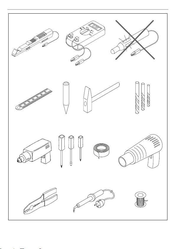
voltmeter (fig. 1 2, page 2).
Test lamps with a bulb (fig. 1 3, page 2) consume voltages which are too high and can
damage the vehicle's electronic system.
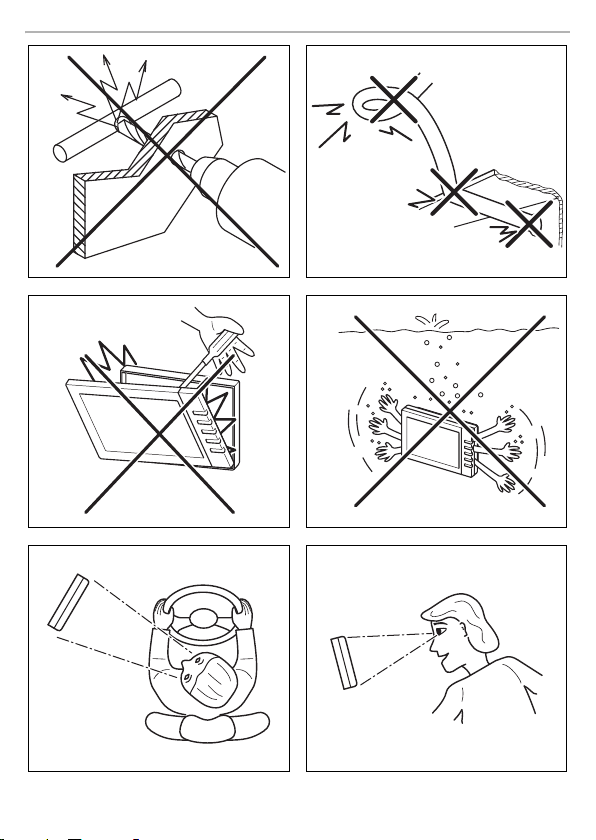
– They are not kinked or twisted
– They do not rub on edges
– They are not laid in sharp-edged ducts without protection (fig. 3, page 3).
for example on existing cables.
CAUTION!
• People (including children) whose physical, sensory or mental capacities or whose
lack of experience or knowledge prevent them from using this product safely
should not use it without the supervision or instruction of a responsible person.
• Do not open the monitor (fig. 4, page 3).
• Do not submerge the monitor in water (fig. 5, page 3); the monitor is not
waterproof.
• The monitor must not impair your vision when driving (fig. 8, page 4).
• Do not operate the monitor with wet hands.
• Do not operate the monitor if the housing has been damaged.
10

PerfectView M55L, M75L Scope of delivery
EN
NOTICE!
A
• Connect it to the correct voltage.
• Do not use the monitor in areas which
– Are subjected to direct sunlight,
– Are subject to strong temperature fluctuations,
– Have high levels of humidity,
– Are poorly ventilated,
– Are dusty or oily.
• Do not press against the LCD display.
• Do not drop the monitor.
• If you use the monitor in vehicles, the vehicle sh ould be running during operation to
prevent the vehicle battery from discharging.
• The picture quality can be impaired in the vicinity of electromagnetic fields.
For this reason do not mount the monitor near loudspeakers.
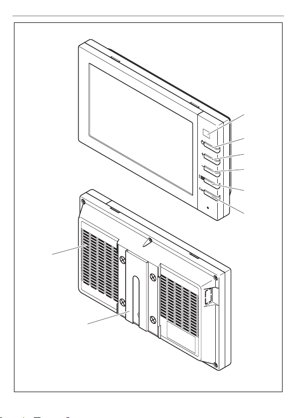
3Scope of delivery
No. in
fig. 9,
page 4
Quantity Description
1 1 Monitor 9600000061 9600000062
2 1 Monitor bracket 9102200193
3 1 Monitor bracket cover 9102200194
– 1 Connection cable 9102200195
––Fastening material
Ref. no.
M55L M75L
4 Accessories
Available as accessories (not included in the scope of delivery):
Description Ref. no.
IR remote control 9102200199
Sun visor for M55L 9102200200
Sun visor for M75L 9102200201
11

Intended use PerfectView M55L, M75L
EN
5Intended use
The LCD monitors PerfectView M55L (ref. no. 9600000061) and M75L (ref. no. 96000000 62) are
monitors which are primarily intended for use in vehicles. They can be used together with cameras
(e.g. a reversing video system) or other video sources.
The LCD monitors are designed for use in all vehicles.
The LCD monitor are designed for leisure use.
6 Technical description
6.1 Function description
The LCD monitor can be connected to cameras (e.g. reversing video systems) or other video
sources (e.g. DVD players). It is possible to switch back and forth between video sources.
The monitor features control cables which allow the cameras to be activated automatically.
It can operate up to three cameras.
It can be used with a RAM mount.
12

PerfectView M55L, M75L Technical description
EN
6.2 Control elements
The following control elements are located on the monitor:
No. in
fig. 0,
page 5
Description
1 Sensor window for the dimmer function.
2 P Switches the monitor on and off.
3 + 1. Increases the brightness.
4 – 1. Reduces the brightness.
51.Switches the menu on.
6 CAM Switches from one camera to the next.
7Monitor bracket
8 Loudspeaker
Description
The brightness of the display is automatically adapted to the
ambient light.
The button lights up red when the monitor is in standby. It lights up
green when the monitor is switched on.
2. Increases the value of the selected parameter if a menu is
opened.
2. Reduces the value of the selected parameter if a menu is
opened.
2. Calls up the parameters for setting.
The parameters are distributed over four screen pages in the
following order:
Page 1: Picture
–Brightness
–Contrast
–Colour
–Volume
–Auto Dim
Page 2: Options
– L anguage: German, English, French, Italian, Dutc h, Spanish,
Portuguese, Russian
– Camera 1/Camera 2/Camera 3: Normal or Mirrored
– Sensitivity: Setting of the switching threshold for the night
dimmer function
Page 3: Default
– Default: Default setting for all parameters
13

Installing the LCD monitor PerfectView M55L, M75L
EN
7 Installing the LCD monitor
7.1 Tools required (fig. 1, page 2)
For installation and assembly you will need the following tools:
• Measuring ruler (4)
• Centre punch (5)
• Hammer (6)
• Drill head set (7)
• Drill (8)
• Screwdriver (9)
To establish and test the electrical connection, the following tools are required:
• Diode test lamp (1) or voltmeter (2)
• Insulating tape (10)
• Heat shrinking sleeve
• Hot air blower (11)
• Crimping tool (12)
• Soldering iron (optional) (13)
• Solder (optional) (14)
• Cable bushing sleeves (optional)
To fasten the cables you may require additional cable binders.
14

PerfectView M55L, M75L Installing the LCD monitor
EN
7.2 Installing the monitor
CAUTION! Beware of injury
!
Observe the following installation instructions:
• Select an installation location that provides an unobstructed view of the monitor (fig. 6 and
• Never install the monitor in areas where your head could hit it or in the airbag deployment path.
• The monitor must not impair your vision when driving (fig. 8, page 4).
• The installation location should be flat.
• Check that there is sufficient space underneath the installation location to attach the washers
• Check beforehand that there is suffici ent space on the other side for the drill head to come out
• Bear in mind the weight of the monitor. Provide reinforcement if necessary (larger washers or
• Make sure you can lay the connection cable to the monitor.
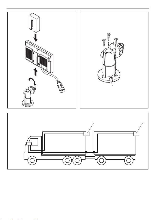
Choosing the installation location (fig. a, page 6)
➤ Place the monitor on the monitor bracket.
➤ Position the monitor and the attached monitor bracket provisionally.
➤ Mark the outlines of the corners of the support base on the dashboard.
➤ Take the monitor off the monitor bracket.
Screwing the monitor bracket onto the dashboard (fig. b, page 6)
➤ Hold the support base within the outlines marked beforehand.
➤ Fasten the monitor bracket with the se lf-tapping screws.
Fastening the monitor
➤ Set the monitor on the monitor bracket and secure it with the knurled nut (fig. a, page 6).
➤ Slide the cover over the monitor bracket on the monitor.
Select the location of the monitor so that it cannot injure the passengers in the vehicle
under any circumstances (e.g. sudden braking, road traffic accidents).
fig. 7, page 3).
This could cause injury if the airbag opens.
and nuts.
(fig. 2, page 3).
plates).
15

Installing the LCD monitor PerfectView M55L, M75L
EN
7.3 Connecting the monitor electrically
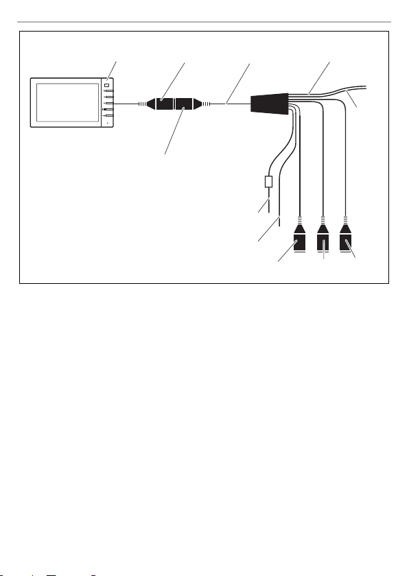
The circuit diagram for the LCD monitor can be found in fig. d, page 7:
No. Description
1Monitor
220-pin socket
3 Monitor line
4 20-pin plug
5 12 – 24 V positive cable (red): connected to the positive pole of the ignition
6 Earth cable (black): connected to the negative po le of the voltage source.
7 Cable (green): control input for video input CAM1,
8 Cable (white): control input for video input CAM2,
9 6-pin CAM1 socket (connection to video source 1)
10 6-pin CAM2 socket (connection to video source 2)
11 6-pin CAM3 socket (connection to video source 3),
A
Observe the following instructions when laying the connection cable:
• If possible, use original ducts for laying the cables, or other suitable options, such as ventilation
grilles. If there are no existing ducts, you must drill a hole of ∅ 22 mm. Check beforehand that
there is sufficient space on the other side for the drill head to emerge (fig. 2, page 3).
• Cover the holes with the feed through (fig. b 1, page 6) in the base of the monitor bracket.
• To prevent damage to the cables, when laying them ensure that there is always sufficient
distance to vehicle components which can become hot (lights, heaters, ventilators etc.).
• When laying the cables (fig. 3, page 3), make sure:
– They are not kinked or twisted
– They do not rub on edges
– They are not laid in sharp-edged ducts without protection.
(connected positive, terminal 5) or the positive pole of the battery
(terminal 30).
such as for connecting the reversing light
such as for the side camera
with video signal detection)
NOTICE!
Cables and connections that are not properly installed will cause malfunctions or
damage to components.
Correct installation of cables and connections ensures lasting and trouble-free
operation of the retrofitted components.
16

PerfectView M55L, M75L Installing the LCD monitor
EN
Connecting the monitor as a reversing video system (fig. d, page 7)
➤ Lay the connection cable for the monitor bracket on the dashboard.
➤ Insert the plug of the monitor cable (2) into the socket (4) of the connection cable (3).
Wait until you hear the plug snap in.
NOTICE! Beware of damage
A
➤ Connect the red and black cables of the connection cable to a suitable voltage supply:
➤ If the monitor is to be activated when reverse gear is selected, connect the green cable (7) to
I
➤ If the monitor is to be activated e.g. when the indicator is flashing, connect the following
I
This control cable is used as a signal cable for the activation of a side camera when an indicator is
flashing, for example.
➤ If necessary, connect the CAM1 socket (9) of the connection cable to the plug of the video
➤ If necessary, connect the CAM2 socket (10) of the connection cable to the plug of video
I
Make sure the polarity is correct when connecting to a voltage source.
– Connect the red cable (5) to terminal 15 (ignition).
– Connect the black cable (6) to terminal 31 (earth).
the positive cable of the reversing light.
NOTE
If voltage is present in the green cable (7), the reversing camera will be activated
automatically. The reversing camera has priority.
control cable to a positive cable of the indicator:
–white cable (8)
NOTE
If voltage is present in this control cable, the video input CAM2 will be activated.
source 1 (e.g. side camera).
source 2 (e.g. camera).
NOTE
Observe the power consumption of the video system. The cameras are equipped with
heaters. A maximum current of 1.5 A can flow (three cameras in heating mode). Use a
dis conn ector swit ch fo r dire ct co nnec tion t o the batt ery. T his a llow s you t o dis conn ect
the video system from the battery easily if you are no longer using the vehicle.
Connec tion for a reversing ca mera
➤ If necessary, connect socket CAM3 (11) of the connection cable to the plug of the additional
reversing camera.
17

Using the LCD monitor PerfectView M55L, M75L
EN
8 Using the LCD monitor
8.1 Switching on the monitor
➤ If the monitor is switched off, press the P button (fig. 0 2, page 5) to switch the monitor on.
➤ The button lights up green.
✓ The picture appears.
8.2 Switching off the monitor
➤ Press the P button (fig. 0 2, page 5) to switch off the monitor.
➤ The button lights up red.
✓ The picture disappears.
8.3 Setting the monitor
To set the monitor to suit your requirements, proceed as follows (fig. 0, page 5):
➤ Press the “ ” button (5) to call up the required parameter.
✓ The parameters to be set appear in the following order:
Page 1: Picture
–Brightness: 0–100
–Contrast: 0–100
–Colour: 0–100
–Volume: 0–100
– Auto Dim On, Off
Page 2: Options
– Language: German, English, French, Italian, Dutch, Spanish, Portuguese, Russian
– Camera 1/Camera 2/Camera 3: Normal or Mirrored
– Sensitivity: 1, 2
Setting of the switching threshold for the night dimmer function to avoid glare.
In dimming mode, the switching threshold can be set at two levels.
Page 3: Default
– Reset (“Default”): Default setting for all parameters
➤ Press the “+” button (3) or the “–” button (4) to set the required parameter.
➤ Press the “+” button (3) to increase the value of the selected parameter.
➤ Press the “–” button (4) to reduce the value of the selected parameter.
8.4 Setting the video source
Proceed as follows to set the video source (fig. 0, page 5):
➤ If you would like to switch to a different video source, press the “CAM” button (6).
✓ The monitor changes the camera in the order “Camera 1 – Camera 2 – Camera 3”.
18

PerfectView M55L, M75L Cleaning and caring for the LCD monitor
EN
8.5 Detecting the trailer camera
This function is required when using a trailer camera (fig. c, page 6) if the system is activated
automatically via the reverse gear.
• One camera connected (e.g. vehicle without a trailer):
the camera connected to CAM1 (1) is activated.
• Two cameras connected (e.g. vehicle with a trailer):
the camera connected to CAM3 (2) is activated (CAM1 is inactive; CAM1 can only be activated
via the “CAM” button)
9 Cleaning and caring for the LCD monitor
NOTICE! Beware of damage
A
➤ Clean the monitor with a soft, damp cloth from time to time.
• Do not use sharp or hard objects for cleaning, as these may damage the monitor.
• Remove the cable before cleaning the monitor to prevent short circuiting.
10 Warranty
The statutory warranty period applies. If the product is defective, please contact the
manu factu rer's b ranch i n your c ountry (see th e back o f the in struct ion ma nual fo r the ad dresse s) or
your retailer.
For repair and guarantee processing, please send the following items:
• Defect components
• A copy of the receipt with purchasing date
• A reason for the claim or description of the fault
11 Disposal
➤ Place the packaging material in the appropriate recycling waste bins wherever possible.
If you wish to finally dispose of the product, ask your local recycling centre or specialist
dealer for details about how to do this in accordance with the applicable disposal
M
regulat ions.
19
Technical data PerfectView M55L, M75L
EN
12 Technical data
M55L M75L
Ref. no.: 9600000061 9600000062
Type: Colour TFT LCD
Display size: 5" (12.7 cm) 7" (17.8 cm)
Brightness: approx. 350 cd/m² Approx. 400 cd/m²
Display resolution, H x V: 385 000 pixels
Video standard: PAL/NTSC (automatic switching)
Operating voltage: 12 – 30 Vg
Power: Max. 10 W
Operating temperature: –20 °C to 70 °C
Storage temperature: –25 °C to 80 °C
Humidity: Max. 85 %
Vibration resistance: 6 g
Dimensions in mm W x H x D: 146 x 87 x 26 190 x 110 x 26
Weight: 350 g 400 g
Approvals
The device has E13 certification.
13
20

PerfectView M55L, M75L Erklärung der Symbole
DE
Bitte lesen Sie diese Anleitung vor Einbau und Inbetriebnahme sorgfältig durch und
bewahren Sie sie auf. Geben Sie sie im Falle einer Weitergabe des Produktes an den
Nutzer weiter.
Inhaltsverzeichnis
1 Erklärung der Symbole . . . . . . . . . . . . . . . . . . . . . . . . . . . . . . . . . . . . . . . . . . . . . . . . . . . . . . 21
2 Sicherheits- und Einbauhinweise. . . . . . . . . . . . . . . . . . . . . . . . . . . . . . . . . . . . . . . . . . . . . . 22
3 Lieferumfang . . . . . . . . . . . . . . . . . . . . . . . . . . . . . . . . . . . . . . . . . . . . . . . . . . . . . . . . . . . . . . 24
4 Zubehör . . . . . . . . . . . . . . . . . . . . . . . . . . . . . . . . . . . . . . . . . . . . . . . . . . . . . . . . . . . . . . . . .24
5 Bestimmungsgemäßer Gebrauch . . . . . . . . . . . . . . . . . . . . . . . . . . . . . . . . . . . . . . . . . . . . .25
6 Technische Beschreibung . . . . . . . . . . . . . . . . . . . . . . . . . . . . . . . . . . . . . . . . . . . . . . . . . . .25
7 LCD-Monitor montieren . . . . . . . . . . . . . . . . . . . . . . . . . . . . . . . . . . . . . . . . . . . . . . . . . . . . .27
8 LCD-Monitor benutzen. . . . . . . . . . . . . . . . . . . . . . . . . . . . . . . . . . . . . . . . . . . . . . . . . . . . . . 31
9 LCD-Monitor pflegen und reinigen . . . . . . . . . . . . . . . . . . . . . . . . . . . . . . . . . . . . . . . . . . . .32
10 Gewährleistung . . . . . . . . . . . . . . . . . . . . . . . . . . . . . . . . . . . . . . . . . . . . . . . . . . . . . . . . . . .32
11 Entsorgung . . . . . . . . . . . . . . . . . . . . . . . . . . . . . . . . . . . . . . . . . . . . . . . . . . . . . . . . . . . . . . .33
12 Technische Daten . . . . . . . . . . . . . . . . . . . . . . . . . . . . . . . . . . . . . . . . . . . . . . . . . . . . . . . . . .33
1 Erklärung der Symbole
VORSIC HT!
!
A
Sicherheitshinweis: Nichtbeachtung kann zu Verletzungen führen.
ACHTUNG!
Nichtbeachtung kann zu Materialschäden führen und die Funktion des Produktes
beeinträchtigen.
I
HINWEIS
Ergänzende Informationen zur Bedienung des Produktes.
21

Sicherheits- und Einbauhinweise PerfectView M55L, M75L
DE
2 Sicherheits- und Einbauhinweise
Beachten Sie die vom Fahrzeughersteller und vom Kfz-Handwerk vorgeschriebenen
Sicherheitshinweise und Auflagen!
Der Hersteller übernimmt in folgenden Fällen keine Haftung für Schäden:
• Montage- oder Anschlussfehler
• Beschädigungen am Produkt durch mechanische Einflüsse und Überspannungen
• Veränderungen am Produkt ohne ausdrückliche Genehmigung vom Hersteller
• Verwendung für andere als die in der Anleitung beschriebenen Zwecke
ACHTUNG! Beschädigungsgefahr!
A
Beachten Sie deshalb folgende Hinweise:
• Verwenden Sie bei Arbeiten an den folgenden Leitungen nur isolierte Kabelschuhe, Stecker
• Verwenden Sie eine Krimpzange (Abb. 1 12, Seite 2) zum Verbinden der Kabel.
• Schrauben Sie das Kabel bei Anschlüssen an Leitung 31 (Masse)
Beim Abklemmen des Minuspols der Batterie verlieren alle flüchtigen Speicher der
Komfortelektronik ihre gespeicherten Daten.
• Klemmen Sie wegen der Kurzschlussgefahr vor Arbeiten an der Fahrzeugelektrik
immer den Minuspol ab.
Bei Fahrzeugen mit Zusatzbatterie müssen Sie an dieser ebenfalls den Minuspol
abklemmen.
• Unzureichende Leitungsverbindungen können zur Folge haben, dass durch
Kurzschluss
– Kabelbrände entstehen,
– der Airbag ausgelöst wird,
– elektronische Steuerungseinrichtungen beschädigt werden,
– elektrische Funktionen ausfallen (Blinker, Bremslicht, Hupe, Zündung, Licht).
und Flachsteckhülsen:
– 30 (Eingang von Batterie Plus direkt),
– 15 (Geschaltetes Plus, hinter Batterie),
– 31 (Rückleitung ab Batterie, Masse),
– 58 (Rückfahrscheinwerfer).
Verwen den S ie kein e Lüsterklemmen.
– m it Kabelschuh und Zahnscheibe an eine fahrzeugeigene Masseschraube oder
– mit Kabelschuh und Blechschraube an das Karosserieblech.
Achten Sie auf eine gute Masseübertragung!
22

PerfectView M55L, M75L Sicherheits- und Einbauhinweise
DE
• Folgende Daten müssen Sie je nach Fahrzeugausstattung neu einstellen:
–Radiocode
–Fahrzeuguhr
– Zeitschaltuhr
– B ordcomputer
– Sitzposition
Hinweise zur Einstellung finden Sie in der jeweiligen Bedienungsanleitung.
Beachten Sie folgende Hinweise bei der Montag e:
VORSIC HT!
!
Beachten Sie folgende Hinweise bei der Arbeit an elektrischen Teilen:
• Benutzen Sie zum Prüfen der Spannung in elektrischen Leitungen nur eine Diodenprüflampe
• Beachten Sie beim Verlegen der elektrischen Anschlüsse, dass diese
• Isolieren Sie alle Verbindungen und Anschlüsse.
• Sichern Sie die Kabel gegen mechanische Beanspruchung durch Kabelbinder oder
Beachten Sie folgende Hinweise beim Umgang mit dem LCD-Monitor:
!
• Befestigen Sie den Monitor so, dass er sich unter keinen Umständen (scharfes
Abbremsen, Verkehrsunfall) lösen und zu Verletzungen der Fahrzeuginsassen
führen kann.
• Befestigen Sie den Monitor nicht im Wirkungsbereich eines Airbags, da bei
Auslösung sonst Verletzungsgefahr besteht.
(Abb. 1 1, Seite 2) oder ein Voltmeter (Abb. 1 2, Seite 2).
Prüflampen mit einem Leuchtkörper (Abb. 1 3, Seite 2) nehmen zu hohe Ströme auf,
wodurch die Fahrzeugelektronik beschädigt werden kann.
– nicht geknickt oder verdreht werden,
–nicht an Kanten scheuern,
– nicht ohne Schutz durch scharfkantige Durchführungen verlegt werden (Abb. 3, Seite 3).
Isolierband, z. B. an vorhandenen Leitungen.
VORSIC HT!
• Personen (einschließlich Kinder), die aufgrund ihrer physischen, sensorischen oder
geistigen Fähigkeiten oder ihrer Unerfahrenheit oder Unkenntnis nicht in der Lage
sind, das Produkt sicher zu benutzen, sollten dieses Produkt nicht ohne Aufsicht
oder Anweisung durch eine verantwortliche Person nutzen.
• Öffnen Sie den Monitor nicht (Abb. 4, Seite 3).
• Tauchen Sie den Monitor keinesfalls in Wasser (Abb. 5, Seite 3); der Monitor ist
nicht wasserdicht.
• Der Monitor darf auf keinen Fall die Sicht beim Autofahren behindern (Abb. 8,
Seite 4).
• Bedienen Sie den Monitor nicht mit nassen Händen.
• Nehmen Sie den Monitor außer Betrieb, wenn das Gehäuse beschädigt ist.
23

Lieferumfang PerfectView M55L, M75L
DE
ACHTUNG!
A
• Schließen Sie die korrekte Spannung an.
• Benutzen Sie den Monitor nicht in Umgebungen, die
– direkter Sonnenstrahlung ausgesetzt sind,
– starken Temperaturschwankungen unterliegen,
– eine hohe Luftfeuchtigkeit aufweisen,
– eine schlechte Ventilation haben,
– staubig oder ölig sind.
• Drücken Sie nicht auf das LCD-Display.
• Lassen Sie den Monitor nicht fallen.
• Wenn Sie den Monitor in Fahrzeugen einsetzen, sollte das Fahrzeug während des
Betriebs laufen, damit die Fahrzeugbatterie nicht entladen wird.
• Die Bildqualität kann sich verschlechtern, wenn starke elektromagnetische Felder in
der Nähe sind.
Montieren Sie den Monitor deshalb nicht in der Nähe von Lautsprechern.
3Lieferumfang
Nr. in
Abb. 9,
Seite 4
Menge Bezeichnung
1 1 Monitor 9600000061 9600000062
2 1 Monitorhalter 9102200193
3 1 Abdeckung
– 1 Anschlusskabel 9102200195
––Befestigungsmaterial
Monitorhalterung
Artikel-Nr.
M55L M75L
9102200194
4Zubehör
Als Zubehör erhältlich (nicht im Lieferumfang enthalten):
Bezeichnung Artikel-Nr.
IR-Fernbedienung 9102200199
Sonnenblende für M55L 9102200200
Sonnenblende für M75L 9102200201
24

PerfectView M55L, M75L Bestimmungsgemäßer Gebrauch
DE
5 Bestimmungsgemäßer Gebrauch
Die LCD-Monitore PerfectView M55L (Art.-Nr. 9600000061) und M75L (Art.-Nr. 9600000062)
sind Monitore, die vorrangig für den Einsatz in Fahrzeugen gedacht sind. Sie können verwendet
werden, um Kameras (z. B. Rückfahrvideosystem) oder andere Videoquellen anzuschließen.
Die LCD-Monitore sind für den Einsatz in allen Fahrzeugen ausgelegt.
Die LCD-Monitore sind für den Freizeitbereich ausgelegt.
6 Technische Beschreibung
6.1 Funktionsbeschreibung
Der LCD-Monitor ist ein Monitor, an den Kameras (z. B. Rückfahrvideosystem) oder andere Videoquellen (z. B. DVD-Gerät) angeschlossen werden können. Zwischen den Videoquellen kann hinund hergeschaltet werden.
Der Monitor bietet Steuerleitungen, mit denen die K ameras automatisch aktiviert werden können.
Er kann bis zu drei Kameras betreiben.
Er ist vorbereitet für den Einsatz einer RAM-Mount-Halterung.
6.2 Bedienelemente
Am Monitor finden Sie folgende Bedienelemente:
Nr. in
Abb. 0,
Seite 5
Bezeichnung
1 Sensorfenster für die Dimmerfunktion
2 P Schaltet den Monitor ein und aus.
3 + 1. Erhöht die Helligkeit.
4 – 1. Verringert die Helligkeit.
Beschreibung
Die Helligkeit des Displays wird automatisch an das Umgebungslicht angepasst.
Die Taste leuchtet rot, wenn der Monitor sich in Standby befindet.
Er leuchtet grün, wenn der Monitor eingeschaltet ist.
2. Erhöht den Wert des ausgewählten Parameters, wenn ein Menü
geöffnet wurde.
2. Verringert den Wert des ausgewählten Parameters, wenn ein
Menü geöffnet wurde.
25

Technische Beschreibung PerfectView M55L, M75L
DE
Nr. in
Abb. 0,
Seite 5
Bezeichnung
5 1. Schaltet das Menü ein.
6 CAM Schaltet von einer Kamera zur nächsten.
7 Monitorhalterung
8Lautsprecher
Beschreibung
2. Ruft die einzustellenden Parameter auf
Die Parameter sind in folgender Reihenfolge auf drei Bildschirm-
seiten verteilt:
Seite 1: Bild
– Helligkeit („Brightness“)
– Kontrast („Contrast“)
–Farbe („Colour“)
– Lautstärke („Volume“)
– Auto-Dimmer („Auto Dim“)
Seite 2: Optionen
– Sprache („Language“): „Deutsch“, „Englisch“,
„Französisch“, „Italienisch“, „Niederländisch“, „Spanisch“,
„Portugiesisch“, „Russisch“
– Kamera1/Kamera2/Kamera3 („Camera1/Camera2/Came-
ra3“): „Normal“ oder „Gespiegelt“
– Empfindlichkeit („Sensitivity“): Einstellung der Einschalt-
schwelle für die Nacht-Dimm-Funktion
Seite 3: Werkeinstellung
– Rücksetzen („Default“): Werkeinstellung aller Parameter
26

PerfectView M55L, M75L LCD-Monitor montieren
DE
7 LCD-Monitor montieren
7.1 Be nö ti gt es Werk ze ug (A bb . 1, Seite 2)
Für Einbau und Montage benötigen Sie folgende Werkzeuge:
• Maßstab (4)
• Körner (5)
• Hammer (6)
• Satz Bohrer (7)
• Bohrmaschine (8)
• Schraubendreher (9)
Für den elektrischen Anschluss und seine Überprüfung benötigen Sie folgende Hilfsmittel:
• Diodenprüflampe (1) oder Voltmeter (2)
• Isolierband (10)
• Wärmeschrumpfschlauch
• Heißluftföhn (11)
• Krimpzange (12)
• Ggf. Lötkolben (13)
• Ggf. Lötzinn (14)
• Ggf. Kabeldurchführungstüllen
Zur Befestigung der Kabel benötigen Sie ggf. noch Kabelbinder.
27

LCD-Monitor montieren PerfectView M55L, M75L
DE
7.2 Monitor montieren
VORSICHT! Verletzungsgefahr!
!
Beachten Sie folgende Hinweise bei der Montag e:
• Wählen Sie einen geeigneten Montageort, so dass Sie ungehinderte Sicht auf den Monitor
• Montieren Sie den Monitor niemals im Kopfaufschlagbereich oder im Wirkungsbereich eines
• Der Monitor darf auf keinen Fall die Sicht beim Autofahren behindern (Abb. 8, Seite 4).
• Der Montageort sollte eben sein.
• Kontrollieren Sie, ob unterhalb des gewählten Montageortes der benötigte Freiraum zum
• Kontrollieren Sie vorher, ob ausreichender Freiraum für den Bohreraustritt vorhanden ist
• Bedenken Sie das Gewicht des Monitors. Sehen Sie ggf. Verstärkungen (größere Unterleg-
• Stellen Sie sicher, dass Sie den Anschl usskabel zum Monitor verlegen können.
Montageort festlegen (Abb. a, Seite 6)
➤ Setzen Sie den Monitor auf den Monitorhalter.
➤ Platzieren Sie den Monitor mit dem angebrachten Halterfuß probeweise.
➤ Zeichnen Sie die Umrisse des Halterfußes auf das Armaturenbrett.
➤ Nehmen Sie den Monitor vom Monitorhalter ab.
Monitorhalter an Armaturenbrett schrauben (Abb. b, Seite 6)
➤ Halten Sie den Halterfuß innerhalb der zuvor gezeichneten Umrisse.
➤ Befestigen Sie den Monitorhalter mit den selbstschneidenden Schrauben.
Monitor befestigen
➤ Setzen Sie den Monitor auf den Monitorhalter und fixieren Sie ihn mit der Rändelmutter
➤ Schieben Sie die Abdeckung über die Monitorhalterung am Monitor.
Wählen Sie den Platz des Monitors so aus, dass unter keinen Umständen (z. B. durch
scharfes Abbremsen, Verkehrsunfall) Fahrzeuginsassen verletzt werden können.
haben (Abb. 6 und Abb. 7, Seite 3).
Airbags. Bei Auslösung besteht sonst Verletzungsgefahr.
Anbringen von Scheiben und Muttern zur Verfügung steht.
(Abb. 2, Seite 3).
scheiben oder Platten) vor.
(Abb. a, Seite 6).
28

PerfectView M55L, M75L LCD-Monitor montieren
DE
7.3 Monitor elektrisch anschließen
Den Schaltplan für den LCD-Monitor finden Sie in Abb. d, Seite 7.
Nr. Bezeichnung
1Monitor
220-polige Buchse
3 Monitorzuleitung
420-poliger Stecker
5 12–24-V-Plus-Kabel (rot): Anschluss an den Pluspol der Zündung
6 Massekabel (schwarz): Anschluss an den Minuspol der Spannungsquelle
7 Kabel (grün): Steuereingang für Videoeingang CAM1,
8 Kabel (weiß): Steuereingang für Videoeingang CAM2,
9 6-polige Buchse CAM1 (Anschluss an Videoquelle 1)
10 6-polige Buchse CAM2 (Anschluss an Videoquelle 2)
11 6-polige Buchse CAM3 (Anschluss an Videoquelle 3,
A
Beachten Sie folgende Hinweise bei der Verlegung der Anschlusskabel:
• Verwenden Sie für die Durchführung der Anschlusskabel nach Möglichkeit Originaldurchführungen oder andere Durchführungsmöglichkeiten, z. B. Lüftungsgitter. Wenn keine Durchführungen vorhanden sind, müssen Sie ein Loch von ∅ 22 mm bohren. Schauen Sie vorher
nach, ob ausreichender Freiraum für den Bohreraustritt vorhanden ist (Abb. 2, Seite 3).
• Decken Sie die Bohrung mit der Durchführung (Abb. b 1, Seite 6) in der Bodenplatte des
Monitorhalters ab.
• Um Beschädigungen am Kabel zu vermeiden, halten Sie beim Verlegen der Kabel immer
ausreichend Abstand zu heißen Fahrzeugteilen (Leuchten, Heizung, Lüftern usw.).
(geschaltetes Plus, Klemme 15) oder den Pluspol der Batterie (Klemme 30)
z. B. für den Anschluss an den Rückfahrscheinwerfer
z. B. Seitenkamera
mit Videosignalerkennung)
ACHTUNG!
Nicht fachgerechte Kabelverlegungen und Kabelverbindungen führen immer wieder
zu Fehlfunktionen oder Beschädigungen von Bauteilen.
Eine korrekte Kabelverlegung und Kabelverbindung ist die Grundvoraussetzung für
eine dauerhafte und fehlerfreie Funktion der nachgerüsteten Komponenten.
29

LCD-Monitor montieren PerfectView M55L, M75L
DE
• Beachten Sie beim Verlegen der Kabel (Abb. 3, Seite 3), dass diese
– nicht stark geknickt oder verdreht werden,
–nicht an Kanten scheuern,
– nicht ohne Schutz durch scharfkantige Durchführungen verlegt werden.
Monitor als Rückfahrvideosystem anschließen (Abb. d, Seite 7)
➤ Verlegen Sie das Anschlusskabel des Monitorhalters am Armaturenbrett.
➤ Stecken Sie den Stecker des Monitorkabels (2) in die Buchse (4) des Anschlusskabels (3).
Der Stecker muss hörbar einrasten.
ACHTUNG! Beschädigungsgefahr!
A
➤ Schließen Sie das rote und schwarze Kabel des Anschlusskabels an eine geeignete
➤ Wenn der Monitor beim Einlegen des Rückwärtsganges aktiviert werden soll, schließen Sie
I
➤ Wenn der Monitor z. B. beim Betätigen des Blinkers aktiviert werden soll, schließen Sie
I
Dieses Steuerkabel dient als Signalleitung zur Akti vierung z. B. einer Seitenkamera bei Betätigung
der Blinker.
➤ Verbinden Sie ggf. die Buchse CAM1 (9) des Anschlusskabels mit dem Stecker der
➤ Verbinden Sie ggf. die Buchse CAM2 (10) des Anschlusskabels mit dem Stecker der
Achten Sie beim Anschluss an die Spannungsquelle auf die richtige Polung.
Spannungsquelle an:
– Schließen Sie das rote Kabel (5) an Klemme 15 (Zündung) an.
– Schließen Sie das schwarze Kabel (6) an Klemme 31 (Masse) an.
das grüne Kabel (7) an die Plusleitung des Rückfahrscheinwerfers an.
HINWEIS
Wenn am grünen Kabel (7) Spannung anliegt, wird die Rückfahrkamera aktiviert.
Die Rückfahrkamera hat Vorrang.
folgendes Steuerkabel an eine Plusleitung der Blinker an:
–weißes Kabel (8)
HINWEIS
Wenn an diesem Steuerkabel Spannung anliegt, wird der Videoeingang CAM2
aktiviert.
Videoquelle 1 (z. B. Seitenkamera).
Videoquelle 2 (z. B. Kamera).
I
30
HINWEIS
Beachten Sie die Stromaufnahme des Videosystems. Die Kameras sin d mit Heizungen
ausgestattet. Es kann maximal ein Strom von 1,5 A fließen (drei Kameras im Heizbetrieb). Verwenden Sie bei direktem Anschluss an die Batterie einen Trennschalter.
Damit können Sie das Videosystem leicht von der Batterie trennen, wenn Sie das
Fahrzeug länger nicht verwenden.

PerfectView M55L, M75L LCD-Monitor benutzen
DE
Anschluss einer Rückfahrkamera
➤ Verbinden Sie ggf. die Buchse CAM3 (11) des Anschlusskabels mit dem Stecker der
zusätzlichen Rückfahrkamera.
8 LCD-Monitor benutzen
8.1 Monitor einschalten
➤ Drücken Sie bei abgeschaltetem Monitor die Taste „P“ (Abb. 0 2, Seite 5), um den Monitor
einzuschalten.
➤ Die Taste leuchtet grün.
✓ Das übertragene Bild erscheint.
8.2 Monitor ausschalten
➤ Drücken Sie die Taste „P“ (Abb. 0 2, Seite 5), um den Monitor auszuschalten.
➤ Die Taste leuchtet rot.
✓ Das Bild erlischt.
8.3 Monitor einstellen
Sie können den Monitor Ihren Wünschen entsprechend wie folgt einstellen (Abb. 0, Seite 5):
➤ Drücken Sie die Taste „ “ (5), um die gewünschten Parameter auszuwählen.
✓ Die einstellbaren Parameter werden in der folgenden Reihenfolge angezeigt:
Seite 1: Bild
– Helligkeit („Brightness“): 0 – 100
– Kontrast („Contrast“): 0 – 100
– Farbe („Colour“): 0 – 100
– Lautstärke („Volume“): 0 – 100
– Auto-Dimmer („Auto Dim“): Ein, Aus
Seite 2: Optionen
– Sprache („Language“): „D eutsch“, „Englisch“, „Französisch“, „Italie nisch“,
„Niederländisch“, „Spanisch“, „Portugiesisch“, „Russisch“
– Kamera1/Kamera2/Kamera3 („Camera1/Camera2/Camera3“): „Normal“ oder
„Gespiegelt“
– Empfindlichkeit („Sensitivity“): 1, 2
Einstellung der Einschaltschwelle für die Nacht-Dimm-Funktion, um Blendung zu
vermeiden.
Im Dimm-Modus kann die Einschaltschwelle in zwei Stufen eingestellt werden
Seite 3: Werkeinstellung
– Rücksetzen („Default“): Werkeinstellung aller Parameter
➤ Drücken Sie die Taste „+“ (3) oder Taste „–“ (4), um den gewünschten Parameter einzustellen.
31

LCD-Monitor pflegen und reinigen PerfectView M55L, M75L
DE
➤ Drücken Sie die Taste „+“ (3), um den Wert des ausgewählten Parameters zu erhöhen.
➤ Drücken Sie die Taste „–“ (4), um den Wert des ausgewählten Parameters zu verringern.
8.4 Videoquelle einstellen
Gehen Sie wie folgt vor, um die Videoquelle einstellen (Abb. 0, Seite 5):
➤ Wenn Sie die Videoquelle umschalten möchten, drücken Sie die Taste „CAM“ (6).
✓ Der Monitor wechselt die Kamera in der Reihenfolge „Kamera 1 – Kamera 2 – Kamera 3“.
8.5 Anhängerkamera erkennen
Diese Funktion wird bei Einsatz einer Anhängerkameras benötigt (Abb. c, Seite 6), wenn das
System automatisch über den Rückwärtsgang aktiviert wird.
• Eine Kamera angeschlossen (z. B. Fahrzeug ohne Anhänger):
die an CAM1 angeschlossene Kamera (1) wird aktiviert
• Zwei Kameras angeschlossen (z. B. Fahrzeug mit Anhänger):
die an CAM 3 angeschlossene Kamera (2) wird aktiviert (CAM1 ist inaktiv; CAM1 kann nur über
die Taste „CAM“ aktiviert werden)
9 LCD-Monitor pflegen und reinigen
ACHTUNG! Beschädigungsgefahr!
A
➤ Reinigen Sie den Monitor gelegentlich mit einem feuchten, weichen Tuch.
• Keine scharfen oder harten Mittel zur Reinigung verwenden, da dies zu einer
Beschädigung des Monitors führen kann.
• Entfernen Sie die Kabel, bevor Sie den Monitor reinigen, damit es nicht zu einem
Kurzschluss kommen kann.
10 Gewährleistung
Es gilt die gesetzliche Gewährleistungsfrist. Sollte das Produkt defekt sein, wenden Sie sich bitte
an die Niederlassung des Herstellers in Ihrem Land (Adressen siehe Rückseite der Anleitung) oder
an Ihren Fachhändler.
Zur Reparatur- bzw. Gewährleistungsbearbeitung müssen Sie Folgendes einschicken:
• defekte Komponenten,
• eine Kopie der Rechnung mit Kaufdatum,
• einen Reklamationsgrund oder eine Fehlerbeschreibung.
32

PerfectView M55L, M75L Entsorgung
DE
11 Entsorgung
➤ Geben Sie das Verpackungsmaterial möglichst in den entsprechenden Recycling-Müll.
Wenn Sie das Produkt endgültig außer Betrieb nehmen, informieren Sie sich bitte beim
nächsten Recyclingcenter oder bei Ihrem Fachhändler über die zutreffenden
M
Entsorgungsvorschriften.
12 Technische Daten
M55L M75L
Art.-Nr.: 9600000061 9600000062
Typ : Co lo r T FT L CD
Displaygröße: 5" (12,7 cm) 7" (17,8 cm)
Helligkeit: ca. 350 cd/m² ca. 400 cd/m²
Displayauflösung H x V: 385000 Pixel
Fernsehnorm: PAL/NTSC (automatische Umschaltung)
Betriebsspannung: 12 – 30 Vg
Leistung: m aximal 10 W
Betriebstemperatur: –20 °C bis 70 °C
Lagertemperatur: –25 °C bis 80 °C
Luftfeuchtigkeit: maximal 85 %
Vibrationsfestigkeit: 6 g
Abmessungen in mm
BxHxT:
Gewicht: 350 g 400 g
Zulassungen
Das Gerät hat die E13-Zulassung.
146 x 87 x 26 190 x 110 x 26
13
33

Explication des symboles PerfectView M55L, M75L
FR
Veuillez lire attentivement cette notice avant le montage et la mise en service. Veuillez
ensuite la conserver. En cas de passer le produit, veuillez le transmettre au nouvel
acquéreur.
Sommaire
1 Explication des symboles . . . . . . . . . . . . . . . . . . . . . . . . . . . . . . . . . . . . . . . . . . . . . . . . . . . .34
2 Consignes de sécurité et instructions de montage. . . . . . . . . . . . . . . . . . . . . . . . . . . . . . . .35
3 Contenu de la livraison . . . . . . . . . . . . . . . . . . . . . . . . . . . . . . . . . . . . . . . . . . . . . . . . . . . . . .37
4 Accessoires . . . . . . . . . . . . . . . . . . . . . . . . . . . . . . . . . . . . . . . . . . . . . . . . . . . . . . . . . . . . . . . 37
5 Usage conforme . . . . . . . . . . . . . . . . . . . . . . . . . . . . . . . . . . . . . . . . . . . . . . . . . . . . . . . . . . . 38
6 Description technique . . . . . . . . . . . . . . . . . . . . . . . . . . . . . . . . . . . . . . . . . . . . . . . . . . . . . .38
7 Montage de l'écran LCD . . . . . . . . . . . . . . . . . . . . . . . . . . . . . . . . . . . . . . . . . . . . . . . . . . . . 40
8 Utilisation de l'écran LCD . . . . . . . . . . . . . . . . . . . . . . . . . . . . . . . . . . . . . . . . . . . . . . . . . . . .44
9 Entretien et nettoyage de l'écran LCD. . . . . . . . . . . . . . . . . . . . . . . . . . . . . . . . . . . . . . . . . . 45
10 Garantie. . . . . . . . . . . . . . . . . . . . . . . . . . . . . . . . . . . . . . . . . . . . . . . . . . . . . . . . . . . . . . . . . . 46
11 Retraitement . . . . . . . . . . . . . . . . . . . . . . . . . . . . . . . . . . . . . . . . . . . . . . . . . . . . . . . . . . . . . .46
12 Caractéristiques techniques. . . . . . . . . . . . . . . . . . . . . . . . . . . . . . . . . . . . . . . . . . . . . . . . . .47
1 Explication des symboles
ATTENTION !
!
A
Consigne de sécurité : le non-respect de ces consignes peut entraîner des blessures.
AVIS !
Le non-respect de ces consigne s peut entraîner des dommages matériels et des dysfonctionnements du produit.
I
34
REMARQUE
Informations complémentaires sur l'utilisation du produit.

PerfectView M55L, M75L Consignes de sécurité et instructions de montage
FR
2 Consignes de sécurité et instructions de montage
Respectez les consignes de sécurité et autres prescriptions imposées par le fabricant
du véhicule et par les professionnels de l’automobile !
Le fabricant décline toute responsabilité pour des dommages dans les cas suivants :
• des défauts de montage ou de raccordement
• des influences mécaniques et des surtensions ayant endommagé le matériel
• des modifications apportées au produit sans autorisation explicite de la part du fabricant
• une utilisation différente de celle décrite dans la notice
AVIS ! Risque d'endommagement !
A
Veuillez respecter les consignes suivantes :
• Pour tous les travaux sur les lignes électriques suivantes, n’utilisez que des cosses de câble,
• Utilisez une pince à sertir (fig. 1 12, page 2) pour relier les câbles.
• Pour les raccordements au câble 31 (masse), vissez le câble
Lorsque vous débranchez le pôle négatif de la batterie, les mémoires volatiles de l’électronique de
confort perdent toutes les données enregistrées.
• Débranchez toujours la borne négative avant de procéder à des travaux sur les
éléments électriques du véhicule afin d’éviter tout risque de court-circuit.
Sur les véhicules équipés d’une batterie supplémentaire, vous devez également
débrancher le pôle négatif de cette dernière.
• Tout raccordement de câbles inadéquat peut provoquer en raison d'un
court-circuit
– des incendies de câbles,
– le déclenchement de l'airbag,
– l'endommagement de dispositifs électroniques de commande,
– la défaillance de fonctions électriques (clignotants, feux stop, klaxon, système
d'allumage, éclairage).
fiches et alvéoles pour contacts plats isolés :
– 30 (entrée directe du pôle positif de la batterie),
– 15 (pôle positif commuté, derrière la batterie),
– 31 (câble de retour à partir de la batterie, masse),
– 58 (feu de recul).
N'utilisez pas de serre-fils.
– à une vis de masse du véhicule, avec une cosse et une rondelle crantée, ou
– à la tôle de carrosserie, avec une cosse et une vis à tôle.
Veillez à ce qu'un bon transfert de masse soit assuré !
35

Consignes de sécurité et instructions de montage PerfectView M55L, M75L
FR
• Selon l'équipement du véhicule, vous devez régler à nouveau les données suivantes :
– Code de l'autoradio
–Horloge du véhicule
– Minuterie
– Ordinateur de bord
– Position des sièges
Les consignes de réglage se trouvent dans le manuel d'utilisation correspondant.
Veuillez respecter les consignes suivantes lors du montage :
ATTENTION !
!
Veuillez respecter les consignes suivantes lors de travaux sur des composants électriques :
• Pour contrôler la tension dans les câbles électriques, utilisez uniquement une lampe-témoin à
• Lors de l'agencement des raccords électriques, veillez à ce que ceux-ci
• Isolez toutes les connexions et tous les raccords.
• Protégez les câbles contre toute contrainte mécanique en les fixant par exemple aux lignes
Veuillez respecter les consignes suivantes lorsque vous manipulez l'écran LCD :
!
• Fixez l'écran de manière à ce qu’il ne puisse en aucun cas (freinage violent,
accident) se détacher et blesser les occupants du véhicule.
• Ne fixez pas l'écran dans le champ d'action d'un airbag, sans quoi il risquerait de
blesser des passagers en cas de déclenchement de l'airbag.
diodes (fig. 1 1, page 2) ou un voltmètre (fig. 1 2, page 2).
Les lampes-témoins (fig. 1 3, page 2) à filament absorbent des courants trop élevés, ce qui
peut endommager l'électronique du véhicule.
– ne soient ni pliés, ni tordus,
– ne frottent pas contre des arêtes,
– ne soient pas placés dans des traversées à arêtes vives sans protection (fig. 3, page 3).
existantes à l'aide de serre-câbles ou de ruban vinyle.
ATTENTION !
• Les personnes (y compris les enfants) qui ne sont pas en mesure d'utiliser l'appareil
en toute sécurité — que ce soit en raison de déficiences physiques, sensorielles ou
mentales ou bien par manque d'expérience ou de connaissances — ne sont pas
au tor isé es à le fai re , sa uf s i u ne p ers on ne g arante de leur sécurité les surveille ou leur
fournit des explications sur son utilisation.
• N'ouvrez pas l'écran (fig. 4, page 3).
• Ne plongez en aucun cas l'écran dans l'eau (fig. 5, page 3) ; l'écran n'est pas
étanche.
• L'écran ne doit en aucun cas gêner la vue du conducteur lors de la conduite (fig. 8,
page 4).
• N'utilisez pas l'écran avec les mains mouillées.
• Mettez l'écran hors service si son boîtier est endommagé.
36

PerfectView M55L, M75L Contenu de la livraison
FR
AVIS !
A
• Veillez à respecter la tension prescrite.
• N'utilisez pas l'écran dans des environnements
– directement exposés aux rayons du soleil,
– soumis à de fortes variations de température,
– présentant une forte humidité,
–mal aérés,
– poussiéreux ou huileux.
• N'appuyez pas sur l'écran LCD.
• Ne faites pas tomber l'écran.
• Si vous utilisez l'écran dans un véhicule, le véhicule doit ê tre en marche pend ant le
fonctionnement de l'écran afin que la batterie du véhicule ne se décharge pas.
• La qualité de l'image peut se dégrader si de puissants champs électromagnétiques
se trouvent à proximité.
Pour cette raison, ne montez pas l'écran à proximité de haut-parleurs.
3 Contenu de la livraison
N° dans
fig. 9,
page 4
Quantité Désignation
1 1 Ecran 9600000061 9600000062
2 1 Support d'écran 9102200193
3 1 Cache de support de
– 1 Câble de raccordement 9102200195
– – Matériel de fixation
l'écran
N° d'article
M55L M75L
9102200194
4 Accessoires
Disponibles en accessoires (non compris dans la livraison) :
Désignation N° d'article
Télécommande infrarouge 9102200199
Pare-soleil pour M55L 9102200200
Pare-soleil pour M75L 9102200201
37

Usage conforme PerfectView M55L, M75L
FR
5Usage conforme
Les écrans LCD PerfectView M55L (n° d'art. 9600000061) et M75L (n° d'art. 9600000062) sont
des écrans principalement conçus pour une utilisation dans les véhicules. Ils peuvent être utilisés
pour raccorder des caméras (p. ex. un système vidéo de recul) ou d'autres sources vidéo.
Les écrans LCD sont adaptés à l'utilisation dans tous les véhicules.
Les écrans LCD sont conçus pour une utilisation de loisirs et non pour une utilisation
professionnelle.
6 Description technique
6.1 Description du fonctionnement
L'écran LCD est un écran auquel des caméras (p. ex. système vidéo de recul) ou d'autres sources
vidéo (p. ex. lecteur DVD) peuvent être raccordées. Il est possible de commuter entre les
différentes sources vidéo.
L'écran dispose de lignes de commande qui permettent d'activer automatiqueme nt les caméras.
Il peut gérer jusqu'à trois caméras.
Il est prévu pour une utilisation dans une fixation RAM-Mount.
6.2 Éléments de commande
L'écran est équipé des éléments de commande suivants :
N° dans
fig. 0,
page 5
Désignation
1 Fenêtre de détection pour le variateur de lumière
2 P Permet d'allumer et d'éteindre le moniteur.
3 + 1. Permet d'augmenter la luminosité.
4 – 1. Permet de réduire la luminosité.
Description
La luminosité de l'écran est automatiquement adaptée à la
luminosité environnante.
La touche s'allume en rouge lorsque l'écran se trouve en mode de
veille. La touche est allumée en vert lorsque l'écran est allumé.
2. Augmente la valeur du paramètre sélectionné quand un menu a
été ouvert.
2. Diminue la valeur du paramètre sélectionné quand un menu a
été ouvert.
38

PerfectView M55L, M75L Description technique
FR
N° dans
fig. 0,
page 5
Désignation
5 1. Active le menu.
6 CAM Commute d'une caméra à l'autre.
7 Support de l'écran
8Haut-parleur
Description
2. Permet d'accéder aux paramètres à régler.
Les paramètres sont répartis dans l'ordre suivant sur trois pages
d'écran :
Page 1 : Image
– Luminosité (« Brightness »)
–Contraste («Contrast»)
– Couleur (« Colour »)
– Volume (« Volume »)
– Auto-Dimmer (« Auto Dim »)
Page 2 : Options
– Langue (« Language ») : « Allemand », « Anglais »,
«Français», «Italien», «Néerlandais», «Espagnol»,
«Portugais», «Russe»
– Caméra1/Caméra2/Caméra3
(« Camera1/Camera2/Camera3 ») : « Normal » ou « Miroir »
– Sensibilité (« Sensitivity ») : Réglage du seuil de commutation
pour la fonction de variation de nuit
Page 3 : réglage par défaut
– Réinitialisation (« Default ») : réglage d'usine de tous les
paramètres
39

Montage de l'écran LCD PerfectView M55L, M75L
FR
7Montage de l'écran LCD
7.1 Outils nécessaires (fig. 1, page 2)
Pour la mise en place et le montage, vous devez disposer des outils suivants :
• Mètre (4)
• Pointeau (5)
• Marteau (6)
• Jeu de mèches (7)
• Perceuse (8)
• Tournevis (9)
Pour le raccordement électrique et la vérification de celui-ci, vous devez disposer du matériel
suivant :
• Lampe étalon à diode (1) ou voltmètre (2)
• Ruban vinyle (10)
• Gaine thermorétractable
• Souffleur air chaud (11)
• Pince de sertissage (12)
• Si nécessaire : fer à souder (13)
• Si nécessaire : étain à souder (14)
• Si nécessaire, passe-câbles
Pour la fixation des câbles, vous aurez éventuellement besoin de serre-fils supplémentaires.
40

PerfectView M55L, M75L Montage de l'écran LCD
FR
7.2 M on ta ge de l 'é cra n
ATTENTION ! Risque de blessures !
!
Veuillez respecter les consignes suivantes lors du montage :
• Choisissez un emplacement adéquat de manière à ce que l'écran soit bien visible (fig. 6 et
• Ne montez jamais l'écran dans la zone d'impact de la tête ou dans la zone de gonflage d'un
• L'écran ne doit en aucun cas gêner la vue du conducteur lors de la conduite (fig. 8, page 4).
• L'emplacement de montage choisi doit être plan.
• Vérifiez que vous disposez de l'espace nécessaire aux rondelles et aux écrous sous
• Vérifiez avant le perçage qu'il y a un es pace suffisant de l'autre côté du trou pour le passage de
• Tenez compte du poids de l'écran. Prévoyez si nécessaire des renforts (plaques ou rondelles
• Assurez-vous de pouvoir poser le câble de raccordement à l'écran.
Détermination de l'emplacement de montage (fig. a, page 6)
➤ Placez le moniteur sur le support d'écran.
➤ Faites un essai de mise en place du moniteur et de son pied.
➤ Marquez les contours du pied sur le tableau de bord.
➤ Retirez l'écran de son support.
Vissage du support d'écran au tableau de bord (fig. b, page 6)
➤ Maintenez le pied à l'intérieur du tracé des contours.
➤ Fixez le support de l'écran avec les vis auto-perceuses.
Fixation de l'écran
➤ Placez l'écran sur le support d'écran et fixez-le avec la vis moletée (fig. a, page 6).
➤ Faites coulisser le cache sur le support de l'écran au niveau de l'écran.
Installez l'écran à un endroit où il ne risquera en aucun cas de blesser les occupants du
véhicule (p. ex. en cas de freinage violent ou d'accident).
fig. 7, page 3).
airbag. Ce dernier risquerait sinon de blesser les passagers en se déclenchant.
l'emplacement de montage choisi.
la mèche (fig. 2, page 3).
de grande taille).
41

Montage de l'écran LCD PerfectView M55L, M75L
FR
7.3 Raccordement électrique de l'écran
Le schéma électrique de l'écran LCD se trouve à la fig. d, page 7.
Nº Désignation
1Moniteur
2 Prise femelle à 20 pôles
3 Ligne d'alimentation de l'écran
4 Connecteur à 20 pôles
5 Câble 12 – 24 V positif (rouge) : raccordement au pôle positif de l'allumage
6 Câble de masse (noir) : raccordement au pôle négatif de la source de ten-
7 Câble (vert) : entrée de commande pour entrée vidéo CAM1,
8 Câble (blanc) : entrée de commande pour entrée vidéo CAM2,
9 Douille à 6 pôles CAM1 (raccordement à la source vidéo 1)
10 Douille à 6 pôles CAM2 (raccordement à la source vidéo 2)
11 Douille à 6 pôles CAM3 (raccordement à la source vidéo 3,
A
Veillez à respecter les consignes suivantes lors de la pose des câbles de raccordement :
• Pour la pose des câbles de raccordement, utilisez si possible des passages existants ou d'autres
possibilités de passage telles que les grilles d'aération. Si aucun passage n'est disponible, vous
devez percer un trou de∅ 22 mm. Vérifiez avant le perçage qu'il y a un espace suffisant pour la
sortie de la mèche de l'autre côté du trou (fig. 2, page 3).
• Recouvrez l'alésage avec le passe-câbles (fig. b 1, page 6) dans la plaque du socle du support
de l'écran.
• Installez les câbles à une distance suffisante des éléments chauds du véhicule (éclairages,
chauffage, ventilateurs, etc.) qui pourraient les endommager.
(pôle positif connecté, borne 15) ou au pôle positif de la batterie (borne 30)
sion
p. ex. pour le raccordement au feu de recul
p. ex. caméra latérale
avec reconnaissance du signal vidéo)
AVIS !
Toute erreur de pose ou de branchement des câbles entraîne presque toujours des
dysfonctionnements ou des détériorations des composants.
Une pose et un branchement corrects des câbles sont indispensables au fonctionnement durable et fiable des composants que vous installez.
42

PerfectView M55L, M75L Montage de l'écran LCD
FR
• Lors de la pose des câbles(fig. 3, page 3), veillez à ce que ceux-ci
– ne soient ni fortement pliés, ni tordus,
– ne frottent pas contre des arêtes,
– ne soient pas placés dans des traversées à arêtes vives sans protection.
Raccordement de l'écran au système vidéo de recul (fig. d, page 7)
➤ Procédez à la pose du câble de raccordement du support d'écran sur le tableau de bord.
➤ Introduisez la prise mâle du câble de l'écran (2) dans la prise femelle (4) du câble de
raccordement (3).
La fiche doit s'enclencher de manière audible.
AVIS ! Risque d'endommagement !
A
➤ Raccordez le câble rouge et le câble noir du câble de raccordement à une source de tension
➤ Si le moniteur doit être activé lorsque la marche arrière est enclenchée, raccordez le câble
I
➤ Lorsque le moniteur doit être activé p. ex. lorsque le clignotant est utilisé, raccordez le câble
I
Ce câble sert de ligne de signalisation pour l'activation p. ex. d'une caméra latérale lorsque le
clignotant est utilisé.
➤ Raccordez éventuellement la prise CAM1 (9) du câble de raccordement au connecteur de la
➤ Raccordez éventuellement la prise CAM2 (10) du câble de raccordement au connecteur de la
Lors du raccordement à la source de tension, veillez à respecter la polarité.
adéquate :
– Raccordez le câble rouge (5) à la borne 15 (contact).
–Raccordez le câble noir (6) à la borne 31 (masse).
vert (7) à la ligne positive du feu de recul.
REMARQUE
Lorsque le câble vert (7) est sou s tension, la camér a de recul est activ ée. La caméra de
recul a la priorité.
suivant à une ligne positive du clignotant :
–câble blanc (8)
REMARQUE
Si ce câble est sous tension, l'entrée vidéo CAM2 est activée.
source vidéo 1 (p. ex. caméra latérale).
source vidéo 2 (p. ex. caméra).
I
REMARQUE
Tenez compte de l'intensité absorbée par le système vidéo. Les caméras sont
équipées de chauffages. Le courant ne peut pas dépasser 1,5 A (trois caméras en
mode chauffage). Utilisez un disjoncteur en cas de raccordement direct à la batterie.
Vous pouvez ainsi débrancher facilement le système vidéo de la batterie lorsque le
véhicule n'est pas utilisé pendant longtemps.
43

Utilisation de l'écran LCD PerfectView M55L, M75L
FR
Raccordement d'une caméra de recul
➤ Raccordez éventuellement la prise CAM3 (11) du câble de raccordement au co nnecteur d e la
caméra de recul supplémentaire.
8 Utilisation de l'écran LCD
8.1 Mise en marche de l'écran
➤ Lorsque l'écran est éteint, appuyez sur la touche « P » (fig. 0 2, page 5) pour mettre l'écran
en marche.
➤ La touche s'allume en vert.
✓ L'image est retransmise.
8.2 Mise à l'arrêt de l'écran
➤ Appuyez sur la touche « P » (fig. 0 2, page 5) pour éteindre l'écran.
➤ La touche s'allume en rouge.
✓ L'image disparaît.
8.3 Réglage de l'écran
Vous pouvez régler l'écran à votre convenance comme suit (fig. 0, page 5) :
➤ Appuyez sur la touche « » (5), pour sélectionner les paramètres souhaités :
✓ Les paramètres réglables sont affichés dans l'ordre suivant :
Page 1 : Image
– Luminosité (« Brightness ») : 0 – 100
– Contraste (« Contrast ») : 0 – 100
– Couleur (« Colour ») : 0 – 100
– Volume (« Volume ») 0 – 100
– Auto-Dimmer (« Auto Dim ») : Marche, Arrêt
Page 2 : Options
– Langue («Language»): «Allemand», «Anglais», «Français», «Italien», «Néerlandais»,
«Espagnol», «Portugais», «Russe»
– Caméra1/Caméra2/Caméra3 (« Camera1/Camera2/Camera3 ») : « Normal » ou « Miroir »
– Sensibilité (« Sensitivity ») : 1, 2
Réglage du seuil de commutation pour la fonction de variation de nuit, afin d'éviter l'aveu-
glement.
En mode variateur, le seuil de commutation possède deux niveaux de réglage
44

PerfectView M55L, M75L Entretien et nettoyage de l'écran LCD
FR
Page 3 : réglage par défaut
– Réinitialisation (« Default ») : réglage d'usine de tous les paramètres
➤ Appuyez sur la touche « + » (3) ou sur la touche « – » (4) pour régler le paramètre souhaité.
➤ Appuyez sur la touche « + » (3) pour augmenter la valeur du paramètre sélectionné.
➤ Appuyez sur la touche « – » (4) pour diminuer la valeur du paramètre sélectionné.
8.4 Réglage de la source vidéo
Procédez de la manière suivante pour régler la source vidéo (fig. 0, page 5) :
➤ Afin de commuter la source vidéo, appuyez sur la touche « CAM » (6).
✓ L'écran change de caméra dans l'ordre suivant : « Caméra 1 – Caméra 2 – Caméra 3 ».
8.5 Détection de la caméra de la remorque
Cette fonction est nécessaire en cas d'utilisation d'une camé ra de remorque (fig. c, page 6), si le
système est activé automatiquement par la marche arrière.
• Une caméra raccordée (p. ex. véhicule sans remorque) :
la caméra raccordée à CAM1 (1) est activée
• Deux caméras raccordées (p. ex. véhicule avec remorque) :
la caméra raccordée à CAM3 (2) est activée (CAM1 est inactive ; CAM1 ne peut être a ctivée que
par la touche « CAM »)
9 Entretien et nettoyage de l'écran LCD
AVIS ! Risque d'endommagement !
A
➤ Nettoyez de temps en temps l'écran avec un chiffon humide.
• N’utilisez aucun objet coupant ou dur pour le nettoyage. Cela pourrait endommager l'écran.
• Avant de nettoyer l'écran, veuillez retirer les câbles afin de ne pas provoquer de
court-circuit.
45

Garantie PerfectView M55L, M75L
FR
10 Garantie
Le délai légal de garantie s'applique. Si le produit s'avérait défectueux, veuillez vous adresser à la
filiale du fabricant située dans votre pays (voir adresses au verso du présent manuel) ou à votre
revendeur spécialisé.
Pour toute réparation ou autre prestation de garantie, veuillez joindre à l'appareil les documents
suivants :
• composants défectueux,
• une copie de la facture avec la date d'achat,
• le motif de la réclamation ou une description du dysfonctionnement.
11 Retraitement
➤ Jetez les emballages dans les conteneurs de déchets recyclables prévus à cet effet.
Lorsque vous mettrez votre produit définitivement hors service, informez-vous auprès
du centre de recyclage le plus proche ou auprès de votre revendeur spécialisé sur les
M
prescriptions relatives au retraitement des déchets.
46

PerfectView M55L, M75L Caractéristiques techniques
FR
12 Caractéristiques techniques
M55L M75L
N° d'art. : 9600000061 9600000062
Type : Couleur TFT LCD
Taille de l'écran : 5" (12,7 cm) 7" (17,8 cm)
Luminosité : env. 350 cd/m² env. 400 cd/m²
Résolution de l'écran H x V :
Norme de télévision : PAL/NTSC (commutation automatique)
Tension de service : 12 – 30 Vg
Puissance : maximum 10 W
Température de
fonctionnement : –20 °C à 70 °C
Température de stockage : –25 °C à 80 °C
Humidité de l'air : 85 % maximum
Résistance aux vibrations : 6 g
Dimensions l x h x p en mm : 146 x 87 x 26 190 x 110 x 26
Poids : 350 g 400 g
Certifications
Cet appareil possède la certification E13.
385 000 pixels
13
47

Explicación de los símbolos PerfectView M55L, M75L
ES
Lea detenidamente estas instrucciones antes de llevar a cabo la instalación y puesta en
funcionamiento, y consérvelas en un lugar seguro. En caso de vender o entregar el producto a otra persona, entregue también estas instrucciones.
Índice
1 Explicación de los símbolos . . . . . . . . . . . . . . . . . . . . . . . . . . . . . . . . . . . . . . . . . . . . . . . . . . 48
2 Indicaciones de seguridad y montaje . . . . . . . . . . . . . . . . . . . . . . . . . . . . . . . . . . . . . . . . . . 49
3 Volumen de entrega . . . . . . . . . . . . . . . . . . . . . . . . . . . . . . . . . . . . . . . . . . . . . . . . . . . . . . . . 51
4 Accesorios . . . . . . . . . . . . . . . . . . . . . . . . . . . . . . . . . . . . . . . . . . . . . . . . . . . . . . . . . . . . . . . 51
5 Uso adecuado. . . . . . . . . . . . . . . . . . . . . . . . . . . . . . . . . . . . . . . . . . . . . . . . . . . . . . . . . . . . . 52
6 Descripción técnica . . . . . . . . . . . . . . . . . . . . . . . . . . . . . . . . . . . . . . . . . . . . . . . . . . . . . . . . 52
7 Montaje del monitor LCD . . . . . . . . . . . . . . . . . . . . . . . . . . . . . . . . . . . . . . . . . . . . . . . . . . . . 54
8 Uso del monitor LCD . . . . . . . . . . . . . . . . . . . . . . . . . . . . . . . . . . . . . . . . . . . . . . . . . . . . . . . 58
9 Limpieza y cuidado del monitor LCD . . . . . . . . . . . . . . . . . . . . . . . . . . . . . . . . . . . . . . . . . . . 59
10 Garantía legal . . . . . . . . . . . . . . . . . . . . . . . . . . . . . . . . . . . . . . . . . . . . . . . . . . . . . . . . . . . . . 59
11 Gestión de residuos . . . . . . . . . . . . . . . . . . . . . . . . . . . . . . . . . . . . . . . . . . . . . . . . . . . . . . . . 60
12 Datos técnicos . . . . . . . . . . . . . . . . . . . . . . . . . . . . . . . . . . . . . . . . . . . . . . . . . . . . . . . . . . . .60
1 Explicación de los símbolos
¡ATENCIÓN!
!
A
Indicación de seguridad: su incumplimiento puede acarrear lesiones.
¡AVISO!
Su incumplimiento puede acarrear daños materiales y perjudicar el correcto funcionamiento del producto.
I
48
NOTA
Información adicional para el manejo del producto.

PerfectView M55L, M75L Indicaciones de seguridad y montaje
ES
2 Indicaciones de seguridad y montaje
Tenga en cuenta las indicaciones de seguridad y la documentación suministrada por el
fabricante y el taller del vehículo.
El fabricante declina toda responsabilidad ante daños ocurridos en los siguientes casos:
• errores de montaje o de conexión
• daños en el producto debido a influencias mecánicas y sobretensiones
• modificaciones realizadas en el producto sin el expreso consentimiento del fabricante
• utilización del aparato para fines distintos a los descritos en las instrucciones
¡AVISO! Peligro de ocasionar daños materiales
A
Por ello, observe las siguientes indicaciones:
• Al trabajar en las siguientes líneas, utilice solo terminales de cable, clavijas y manguitos planos
• Utilice una crimpadora (fig. 1 12, página 2) para empalmar los cables.
• En el caso de conexiones a la línea 31 (masa), atornille el cable
Tenga en cuenta que al desembornar el polo negativo de la batería se perderán todos los datos
almacenados en las memorias volátiles de la electrónica de confort.
• Desemborne el polo negativo siempre que vaya a trabajar en el sistema eléctrico
del vehículo para evitar un cortocircuito.
Desemborne también el polo negativo de la batería adicional en aquellos vehículos
que dispongan de una.
• Las conexiones eléctricas insuficientes pueden provocar que, a causa de un
cortocircuito:
– se quemen los cables,
– se dispare el airbag,
– resulten dañados los dispositivos electrónicos de control,
– queden sin funcionamiento determinadas funciones eléctricas (intermitentes,
luz de freno, claxon, encendido, luz).
que estén provistos de aislamiento:
– 30 (entrada del polo positivo directo de la batería),
– 15 (polo positivo conectado, detrás de la batería),
– 31 (línea de retorno desde la batería, masa),
– 58 (luz de marcha atrás).
No utilice ninguna regleta.
– con terminal de cable y arandela dentada a un tornillo de masa del vehículo, o bien,
– con terminal de cable y tornillo para chapa a la chapa de la carrocería.
Asegúrese de que se produzca una correcta transmisión a masa.
49

Indicaciones de seguridad y montaje PerfectView M55L, M75L
ES
• Dependiendo del equipamiento del vehículo, deberá volver a configurar los siguientes datos:
– código de radio
– reloj del vehículo
– temporizador
– ordenador de a bordo
– posición del asiento
Las indicaciones para realizar las configuraciones se encuentran en las instrucciones de uso
correspondientes.
Tenga en cuenta las siguientes indicaciones durante el montaje:
¡ATENCIÓN!
!
Tenga en cuenta las siguientes indicaciones al trabajar en los componentes eléctricos:
• Para comprobar la tensión en los cables eléctricos utilice solamente un diodo de comproba-
• Al tender los cables eléctricos preste atención a que éstos:
• Aísle todos los empalmes y conexiones.
• Asegure los cables frente a tracciones mecánicas mediante abrazaderas para cables o cinta
Tenga en cuenta las siguientes indicaciones al manipular el monitor LCD:
!
• Fije el monitor de forma que no pueda soltarse bajo ninguna circunstancia (por
ejemplo, en caso de frenazos o accidente) y, como consecuencia, ocasionar
lesiones a los ocupantes del vehículo.
• No monte el monitor en el área de acción de un airbag debido al peligro de
lesiones existente en caso de que el airbag se active.
ción (fig. 1 1, página 2) o un voltímetro (fig. 1 2, página 2).
Las lámparas de prueba con un elemento luminoso (fig. 1 3, pág ina 2) tienen un consumo de
corriente demasiado elevado, por lo que puede dañarse el sistema electrónico del vehículo.
– no se doblen ni se tuerzan,
– no rocen con bordes,
– no se tiendan sin protección a través de guías con aristas afiladas (fig. 3, página 3).
aislante, por ejemplo, fijándolos a las líneas ya existentes.
¡ATENCIÓN!
• No deben utilizar este producto sin la vigilancia o las instrucciones de una persona
responsable las personas (incluidos los niños) que, debido a sus capacidades
físicas, sensoriales o mentales, a su falta de experiencia o a desconocimiento,
no puedan utilizar el producto de forma segura.
• No abra el monitor (fig. 4, página 3).
• No sumerja nunca el monitor en agua (fig. 5, página3), pues no es hermético al
agua.
• En ningún caso el monitor debe dificultar la visión durante la conducción (fig. 8,
página 4).
• No manipule el monitor con las manos mojadas.
• No ponga en funcionamiento el monitor si la carcasa ha sufrido daños.
50

PerfectView M55L, M75L Volumen de entrega
ES
¡AVISO!
A
• Conecte la tensión correcta.
• No utilice el monitor en entornos con:
– exposición directa a los rayos del sol,
– grandes cambios de temperatura,
– elevada humedad del aire,
– una ve ntilación insuficiente,
– elevada concentración del polvo o aceite.
• No presione sobre la pantalla LCD.
• No deje caer el monitor.
• Si se utiliza el monitor dentro del vehículo, éste debe permanecer con el motor en
marcha a fin de evitar que se descargue la batería.
• Es posible que empeore la calidad de la imagen si se encuentra cerca de campos
electromagnéticos.
Por este motivo, evite montar el monitor cerca de altavoces.
3 Volumen de entrega
N.º en
fig. 9,
página 4
Cantidad Denominación
1 1 Monitor 9600000061 9600000062
2 1 Soporte del monitor 9102200193
3 1 Cubierta del soporte del
– 1 Cable de conexión 9102200195
––Material de fijación
monitor
N.° de artículo
M55L M75L
9102200194
4 Accesorios
Disponibles como accesorio (no incluidos en el volumen de entrega):
Denominación N.° de artículo
Mando a distancia por infrarrojos 9102200199
Parasol para M55L 9102200200
Parasol para M75L 9102200201
51

Uso adecuado PerfectView M55L, M75L
ES
5Uso adecuado
Los monitores LCD PerfectView M55L (n.° de art. 9600000061) y M75L (n.° de art. 9600000062)
son monitores concebidos básicamente para su uso en vehículos. Pueden utilizarse para conectar
cámaras (por ejemplo, sistema de vídeo para marcha atrás) u otras fuentes de vídeo.
Los monitores LCD están diseñados para su uso en cualquier vehículo.
Los monitores LCD están concebidos para el ámbito de ocio.
6 Descripción técnica
6.1 Descripción del funcionamiento
Al monitor LCD pueden conectarse cámaras (p.ej. sistema de vídeo para marcha atrás) u otras
fuentes de vídeo (p.ej. reproductor de DVD). Podrá alternar entre las fuentes de vídeo.
El monitor ofrece líneas de control con las que pueden activarse automáticamente las cámaras.
Puede trabajar con hasta tres cámaras.
Está preparado para el uso de un soporte RAM Mount.
6.2 Elementos de mando
En el monitor se encuentran los siguientes elementos de mando:
N.º en
fig. 0,
página 5
Denominación
1 Ventanilla del sensor para la función de atenuación
2 P Enciende y apaga el monitor.
3 + 1. Aumenta el brillo.
4 – 1. Reduce el brillo.
Descripción
El brillo de la pantalla se adapta automáticamente a la luz del
entorno.
La tecla se ilumina en rojo, cuando el monitor se encuentra en
stand-by. Se ilumina en verde cuando el monitor está encendido.
2. Aumenta el valor del parámetro elegido cuando se abre un
menú.
2. Disminuye el valor del parámetro elegido cuando se abre un
menú.
52

PerfectView M55L, M75L Descripción técnica
ES
N.º en
fig. 0,
página 5
Denominación
5 1. Enciende el menú.
6 CAM Cambia de una cámara a la siguiente.
7Soporte del monitor
8Altavoz
Descripción
2. Abre los parámetros que se desean configurar.
Los parámetros están clasificados en el siguiente orden a lo
largo de tres páginas de pantalla:
Página 1: Imagen
– Brillo (“Brightness”)
–Contraste (“Contrast”)
–Color (“Colour”)
– Volumen (“Volume”)
– Atenuación automática (“Auto Dim”)
Página 2: Opciones
– Idioma (“Language”): “Deutsch” (alemán), “Englisch”
(inglés), “Französisch” (francés), “Italienisch” (italiano),
“Niederländisch” (holandés), “Spanisch” (español),
“Portugiesisch” (portugués), “Russisch” (ruso)
– Cámara1/Cámara2/Cámara3 (“Camera1/Camera2/Came-
ra3”): “Normal” o “Gespiegelt” (reflejada)
– Sensibilidad (“Sensitivity”): Ajuste del umbral de activación
para la función de atenuación nocturna
Página 3: Configuración de fábrica
– Restaurar (“Default”): configuración de fábrica de todos los
parámetros
53

Montaje del monitor LCD PerfectView M55L, M75L
ES
7Montaje del monitor LCD
7.1 Herramientas necesarias (fig. 1, página 2)
Para realizar la instalación y montaje son necesarias las siguientes herramientas:
• regla graduada (4)
• punzón para marcar (5)
• martillo (6)
• juego de brocas (7)
• taladradora (8)
• destornillador (9)
Para realizar la conexión eléctrica y su comprobación, necesitará los siguientes medios
auxiliares:
• diodo de comprobación (1) o voltímetro (2)
• cinta aislante (10)
• tubo termorretráctil
• secador de aire caliente (11)
• crimpadora (12)
• si fuese necesario, soldador de cobre (13)
• si fuese necesario, estaño para soldar (14)
• Si fuese necesario, tubos protectores para los cables
Para la fijación de los cables necesitará adicionalmente abrazaderas para cables.
54

PerfectView M55L, M75L Montaje del monitor LCD
ES
7.2 M on ta je del mo ni to r
¡ATENCIÓN! ¡Peligro de sufrir lesiones!
!
Tenga en cuenta las siguientes indicaciones durante el montaje:
• Elija un lugar de montaje adecuado, de manera que pueda visualizar sin impedimentos el
• Nunca monte el monitor en áreas en las que puedan producirse golpes en la cabeza o en el
• En ningún caso debe el monitor dificultar la visión durante la conducción (fig. 8, página 4).
• El lugar de montaje debe ser llano.
• Asegúrese de que debajo del lugar de montaje elegido haya espacio suficiente para la
• Compruebe previamente si se dispone de espacio libre suficiente para la salida de la broca
• Tenga en cuenta el peso del monitor. En caso necesario, tenga disponibles refuerzos
• Asegúrese de que puede tender correctamente el cable de conexión hacia el monitor.
Definir el lugar de montaje (fig. a, página 6)
➤ Coloque el monitor en su soporte.
➤ Coloque el monitor con la base a modo de prueba.
➤ Dibuje el contorno de la base del soporte sobre el salpicadero.
➤ Separe el monitor de su soporte.
Atornillar el soporte del monitor al salpicadero (fig. b, página 6)
➤ Sujete la base del soporte dentro del contorno dibujado anteriormente.
➤ Fije el soporte del monitor con los tornillos autocortantes.
Fijar el monitor
➤ Coloque el monitor en el s oporte del monitor y fíjelo con la tuerca estriada (fig. a, página 6).
➤ Deslice la cubierta sobre el soporte del monitor.
Monte el monitor en un lugar en el que bajo ninguna circunstancia pueda provocar
heridas a los ocupantes del vehículo (por ejemplo, por frenazos bruscos o accidente).
monitor (fig. 6 y fig. 7, página 3).
campo de acción del airbag debido al peligro de lesiones existente en caso de una activa ción
del mismo.
colocación de arandelas y tuercas.
(fig. 2, página 3).
(arandelas y placas grandes).
55

Montaje del monitor LCD PerfectView M55L, M75L
ES
7.3 Conexión eléctrica del monitor
Consulte la fig. d, página 7 para ver el esquema de conexiones del monitor LCD.
N.° Denominación
1Monitor
2 Hembrilla de 20 polos
3 Cable de alimentación del monitor
4 Clavija de 20 polos
5 Cable positivo de 12 – 24 V (rojo): conexión al polo positivo del encendido
6 Cable de masa (negro): conexión al polo negativo de la fuente de
7 Cable (verde): entrada de control para la entrada de vídeo CAM1,
8 Cable (blanco): entrada de control para la entrada de vídeo CAM2,
9 Hembrilla de 6 polos CAM1 (conexión a la fuente de vídeo 1)
10 Hembrilla de 6 polos CAM2 (conexión a la fuente de vídeo 2)
11 Hembrilla de 6 polos CAM3 (conexión a la fuente de vídeo 3,
A
(polo positivo conectado, borne15) o al polo positivo de la batería
(borne 30)
alimentación.
por ejemplo, para conexión a la luz de marcha atrás
por ejemplo, cámara lateral
con detección de la señal de vídeo)
¡AVISO!
La colocación y las conexiones de cables que no hayan sido realizadas por personal
especializado, generalmente tienen como consecuencia el mal funcionamiento o
daños en los componentes.
La instalación y conexión correctas de los cables son requisitos fundamentales para un
funcionamiento duradero y correcto de los accesorios instalados.
Tenga en cuenta las siguientes indicaciones durante la instalación del cable de conexión:
• Par a ten der lo s cab les d e cone xión util ice, s iempre que sea posible, canales de paso originales
u otras posibilidades, como por ejemplo rejillas de ventilación. Si no existen pasos, deberá
realizar una perforación de ∅ 22 mm. Compruebe previamente si hay suficiente espacio libre
para la salida de la broca (fig. 2, página 3).
• Haga coincidir el o rificio con la escotadura ( fig. b 1, página 6) de la placa base del soporte del
monitor.
• Al colocar los cables, mantenga una distancia suficiente con las piezas del vehículo calientes y
móviles (luces, calefacción, ventiladores etc.), para evitar daños en el cable.
56

PerfectView M55L, M75L Montaje del monitor LCD
ES
• Al tender los cables (fig. 3, página 3) asegúrese de que:
– no se doblen ni se retuerzan,
– no rocen con bordes,
– no se tiendan sin protección a través de guías con aristas afiladas.
Conexión del monitor como sistema de vídeo para marcha atrás (fig. d, página 7)
➤ Tienda el cable de conexión del soporte del monitor en el salpicadero.
➤ Inserte la clavija del cable del monitor (2) en la hembrilla (4) del cable de conexión (3).
La clavija debe encajar produciendo un sonido.
¡AVISO! Peligro de ocasionar daños materiales
A
➤ Conecte los cables rojo y negro del cable de conexión a una fuente de tensión apropiada:
➤ Si desea que el monitor se active al engranar la marcha atrás, conecte el cable verde (7) a la
I
➤ Si desea que el monitor se active p.ej. al accionar el intermitente, conecte el siguiente cable
I
Este cable de control sirve como cable de señal para activar p.ej. una cámara lateral al accionar el
intermitente.
➤ Si es necesario, conecte la hembrilla CAM1 (9) del cable de conexión con la clavija de la fuente
➤ Si es necesario, conecte la hembrilla CAM2 (10) del cable de conexión con la clavija de la
Respete la polaridad adecuada de la fuente de tensión al realizar la conexión.
– Conecte el cable rojo (5) al borne 15 (encendido).
– Conecte el cable negro (6) al borne 31 (masa).
línea positiva de la luz de marcha atrás.
NOTA
Si hay tensión en el cable verde (7), se activa la cámara para marcha atrás. Esta cámara
tiene prioridad.
de control a un cable positivo de los intermitentes:
–cable blanco (8)
NOTA
Si hay tensión en este cable de control, se activa la entrada de vídeo CAM2:
de vídeo 1 (por ejemplo, cámara lateral).
fuente de vídeo 2 (por ejemplo, cámara).
I
NOTA
Preste atención al consumo d e corriente del sistema de vídeo. Las cámaras están equipadas con calefacción. Puede fluir una corriente máxima de 1,5 A (tres cámaras en el
modo de calentamiento). Si realiza una conexión directa a la batería, utilice un seccionador. Así se podrá separar fácilmente el sistema de vídeo de la batería , cuando n o se
utilice el vehículo por un intervalo prolongado.
57

Uso del monitor LCD PerfectView M55L, M75L
ES
Conexió n de una cámara para marcha atrás
➤ En caso necesario, conecte la hembrilla CAM3 (11) del cable de conexión con la clavija de la
cámara para marcha atrás adicional.
8 Uso del monitor LCD
8.1 Encender el monitor
➤ Estando el monitor apagado, pulse la tecla “P” (fig. 0 2, página 5) para encenderlo.
➤ La tecla se ilumina en verde.
✓ Aparece la imagen transmitida.
8.2 Apagar el monitor
➤ Para apagar el monitor pulse la tecla “P” (fig. 0 2, página 5).
➤ La tecla se ilumina en rojo.
✓ La imagen se apaga.
8.3 Configurar el monitor
Puede configurar el monitor a su gusto como se indica a continuación (fig. 0, página 5):
➤ Pulse la tecla “ ” (5) para seleccionar los parámetros que desee.
✓ Los parámetros configurables se muestran en el siguiente orden:
Página 1: Imagen
– Brillo (“Brightness”): 0 – 100
– Contraste (“Contrast”): 0 – 100
– Color (“Colour”): 0 – 100
– Volumen (“Volume”): 0 – 100
– Atenuación automática (“A uto Dim”): activar, desactivar
Página 2: Opciones
– Idioma (“Language”): “Deutsch” (alemán), “Englisch” (inglés), “Französisch” (francés),
“Italienisch” (italiano), “Niederländisch” (holandés), “Spanisch” (español), “Portugiesisch”
(portugués), “Russisch” (ruso)
– Cámara1/Cámara2/Cámara3 (“Camera1/Camera2/Camera3”): “Normal” o “Reflejada”
– Sensibilidad (“Sensitivity”): 1, 2
Ajuste del umbral de activación para la función de atenuación nocturna para evitar
deslumbramiento.
En el modo de atenuación, el umbral de activación se puede ajustar en dos niveles.
58

PerfectView M55L, M75L Limpieza y cuidado del monitor LCD
ES
Página 3: Configuración de fábrica
– Restaurar (“Default”): ajuste de fábrica de todos los parámetros
➤ Pulse la tecla “+” (3) o “–” (4) para ajustar el parámetro que desee.
➤ Pulse la tecla “+” (3) para aumentar el valor del parámetro seleccionado.
➤ Pulse la tecla “–” (4) para disminuir el valor del parámetro seleccionado.
8.4 Ajustar la fuente de vídeo
Para ajustar la fuente de vídeo, proceda como se indica a continuación (fig. 0, página 5):
➤ Para cambiar entre las fuentes de vídeo, pulse la tecla “CAM” (6).
✓ El monitor cambia la cámara en la secuencia “cámara 1 – cámara 2 – cámara 3”.
8.5 Reconocer la cámara del remolque
Esta función es necesaria para utilizar una cámara de remolque (fig. c, página 6) cuando el
sistema se activa automáticamente por medio de la marcha atrás.
• Una cámara conectada (por ejemplo, vehículo sin remolque):
se activa la cámara conectada a CAM1 (1)
• Dos cámaras conectadas (por ejemplo, vehículo con remolque):
se activa la cámara conectada a CAM3 (2) (CAM1 está inactiva; CAM1 solo se puede activar con
la tecla “CAM”)
9 Limpieza y cuidado del monitor LCD
¡AVISO! Peligro de ocasionar daños materiales
A
➤ Limpie el monitor con un paño húmedo y suave cuando sea necesario.
• No utilice ningún instrumento afilado o duro en la limpieza, ya que podría dañar el
monitor.
• Extraiga el cable antes de realizar la limpieza del monitor para evitar que se
produzcan cortocircuitos.
10 Garantía legal
Rige el plazo de garantía legal. Si el producto presenta algún defecto, diríjase a la sucursal del
fabricante de su país (ver direcciones en el dorso de estas instruccione s) o a su establecimiento
especializado.
Para la tramitación de la reparación y de la garantía debe enviar lo siguiente:
• componentes defectuosos,
• una copia de la factura con fecha de compra,
• el motivo de la reclamación o una descripción de la avería.
59

Gestión de residuos PerfectView M55L, M75L
ES
13
11 Gestión de residuos
➤ Deseche el material de embalaje en el contenedor de reciclaje correspondiente.
Cuando vaya a desechar definitivamente el producto, infórmese en el centro de
reciclaje más cercano o en un comercio especializado sobre las normas pertinentes de
M
eliminación de materiales.
12 Datos técnicos
M55L M75L
N.° de art.: 9600000061 9600000062
Tipo: color TFT LCD
Tamaño de pantalla: 5" (12,7 cm) 7" (17,8 cm)
Brillo: 350 cd/m² aprox. 400 cd/m² aprox.
Resolución de la pantalla
H x V: 385.000 píxeles
Norma de televisión: PAL/NTSC (conmutación automática)
Tensión de funcionamiento: 12 – 30 Vg
Potencia: máximo 10 W
Temperatura de
funcionamiento: de –20 °C a 70 °C
Temperatura de
almacenamiento:
Humedad del aire: máximo 85 %
Resistencia a vibraciones: 6 g
Dimensiones en A x H x P: 146 x 87 x 26 190 x 110 x 26
Peso: 350 g 400 g
Homologaciones
El aparato posee la homologación E13.
de –25 °C a 80 °C
60

PerfectView M55L, M75L Explicação dos símbolos
PT
Por favor, leia atentamente este manual antes da montagem e colocação em funcionamento do aparelho e guarde-o em local seguro. Em caso de transmissão do produto,
entregue o manual ao novo utilizador.
Índice
1 Explicação dos símbolos . . . . . . . . . . . . . . . . . . . . . . . . . . . . . . . . . . . . . . . . . . . . . . . . . . . . 61
2 Indicações de segurança e de montagem . . . . . . . . . . . . . . . . . . . . . . . . . . . . . . . . . . . . . . 62
3 Material fornecido . . . . . . . . . . . . . . . . . . . . . . . . . . . . . . . . . . . . . . . . . . . . . . . . . . . . . . . . .64
4 Acessórios. . . . . . . . . . . . . . . . . . . . . . . . . . . . . . . . . . . . . . . . . . . . . . . . . . . . . . . . . . . . . . . .64
5 Utilização adequada . . . . . . . . . . . . . . . . . . . . . . . . . . . . . . . . . . . . . . . . . . . . . . . . . . . . . . . . 65
6 Descrição técnica . . . . . . . . . . . . . . . . . . . . . . . . . . . . . . . . . . . . . . . . . . . . . . . . . . . . . . . . . . 65
7 Montar o monitor LCD . . . . . . . . . . . . . . . . . . . . . . . . . . . . . . . . . . . . . . . . . . . . . . . . . . . . . .67
8 Utilizar o monitor LCD . . . . . . . . . . . . . . . . . . . . . . . . . . . . . . . . . . . . . . . . . . . . . . . . . . . . . . 71
9 Conservar e limpar o monitor LCD. . . . . . . . . . . . . . . . . . . . . . . . . . . . . . . . . . . . . . . . . . . . . 72
10 Garantia. . . . . . . . . . . . . . . . . . . . . . . . . . . . . . . . . . . . . . . . . . . . . . . . . . . . . . . . . . . . . . . . . .72
11 Eliminação . . . . . . . . . . . . . . . . . . . . . . . . . . . . . . . . . . . . . . . . . . . . . . . . . . . . . . . . . . . . . . . . 73
12 Dados técnicos . . . . . . . . . . . . . . . . . . . . . . . . . . . . . . . . . . . . . . . . . . . . . . . . . . . . . . . . . . . . 73
1 Explicação dos símbolos
PRECAUÇÃO!
!
A
Indicação de segurança: o incumprimento pode provocar ferimentos.
NOTA!
O incumprimento pode causar danos materiais e pode prejudicar o funcionamento do
produto.
I
OBSERVAÇÃO
Informações suplementares sobre a operação do produto.
61

Indicações de segurança e de montagem PerfectView M55L, M75L
PT
2 Indicações de segurança e de montagem
Cumpra as indicações de segurança e o especificado na literatura do fabricante do
veículo e das associações profissionais!
O fabricante não se responsabiliza por danos nos seguintes casos:
• Erros de montagem ou de conexão
• Danos no produto resultantes de influências mecânicas e sobretensões
• Alterações ao produto sem autorização expressa do fabricante
• Utilização para outras finalidades que não as descritas no manual de instruções
NOTA! Perigo de danos!
A
Preste, por isso, atenção às s eguintes indicações:
• ao realizar trabalhos nos seguintes cabos, utilize apenas terminais de cabos, fichas e mangas de
• Utilize um alicate de crimpar (fig. 1 12, página 2) para ligar os cabos.
• Aparafuse o cabo por conexões ao cabo 31 (terra)
Ao retirar o borne do polo negativo da bateria, todas as memórias voláteis do sistema elétrico de
comando perdem os seus dados memorizados.
• Antes de efetuar trabalhos no sistema elétrico do veículo, desligue sempre o polo
negativo devido a perigo de curto-circuito.
No caso de veículos com bateria adicional, a mesma também deve ser desligada
do polo negativo.
• Ligações de cabos insuficientes podem ter como consequência um curto-circuito,
– o queimar de cabos,
– o disparo do airbag,
– a danificação dos dispositivos de comando eletrónicos,
– a falha das funç ões elétricas (indicador de mudança de direção, luz dos travões,
buzina, ignição, luzes).
encaixe plano isolados:
– 30 (entrada direta do positivo da bateria),
– 15 (positivo ligado, por detrás da bateria),
– 31 (cabo de retorno a partir da bateria, massa),
– 58 (faróis de marcha-atrás).
Não utilize quaisquer barras de junção.
– com terminal de cabos e arruela dentada a um parafuso de ligação à terra do veículo ou
– com terminal de cabos e parafuso auto roscante à chapa da carroçaria.
Tenha atenção a uma boa transmissão à terra!
62

PerfectView M55L, M75L Indicações de segurança e de montagem
PT
• De acordo com a versão do veículo, terá de configurar novamente os seguintes dados:
– Código do rádio
–Relógio do veículo
– Temporizador
– Computador de bordo
– Posição de utilização
No respe tivo manual de instruções e ncontrará indicações re lativas à regul ação.
Durante a montagem, respeite a s seguintes indicações:
PRECAUÇÃO!
!
Respeite as seguintes indicações durante o trabalho em peças elétricas:
• Para verificar a tensão em ligações elétricas, utilize apenas uma lâmpada de verificação com
• Ao instalar as ligações elétricas tenha atenção para que estas
• Isole todos os cabos e ligações.
• Proteja os cabos contra desgaste mecânico através de braçadeiras de cabos ou fita de
Preste atenção às seguintes indicações durante o manuseamento do monitor LCD:
!
• Fixe o monitor impedindo que este se solte (travagem brusca, acidente) e causar
ferimentos aos ocupantes do veículo.
• Não fixe o monitor na zona de ação de um airbag, uma vez que existiria o perigo de
ferimentos em caso de acidente.
díodos (fig. 1 1, página 2) ou um voltímetro (fig. 1 2, página 2).
As lâmpadas de verificaç ão (fig. 1 3, página 2) com um corpo luminoso co nsomem correntes
muito elevadas o que pode resultar na danificação da eletrónica do veículo.
– não fiquem dobradas ou torcidas,
– não façam fricção em arestas,
– não passem sem proteção por guias de passagem com arestas afiadas (fig. 3, página 3 ).
isolamento, p.ex., nos cabos existentes.
PRECAUÇÃO!
• As pessoas (incluindo crianças) que não estão aptas a utilizar o produto de modo
seguro devido a incapacidade física, sensorial ou mental ou devido à sua inexperiência não devem utilizar o produto sem a supervisão ou as instruções de uma
pessoa responsável.
• Não abra o monitor (fig. 4, página 3).
• Nunca mergulhe o monitor em água (fig. 5, página 3); o monitor não é estanque.
• O monitor não pode, em caso algum, dificultar a visibilidade durante a condução
(fig. 8, página 4).
• Não opere o monitor com as mãos molhadas.
• Desligue o monitor se o corpo apresentar danos.
63

Material fornecido PerfectView M55L, M75L
PT
NOTA!
A
• Ligue a tensão correta.
• Não utilize o monitor em ambientes que
– se encontrem diretamente expostos a radiação solar,
– estejam submetidos a fortes oscilações de temperatura,
– apresentem uma elevada humidade do ar,
– tenham uma má ventilação,
– estejam empoeirados ou contenham óleo.
• Não pressione o monitor LCD.
• Não deixe o monitor cair.
• Se utilizar o monitor em veículos, o veículo deve encontrar-se em funcionamento
para que a sua bateria não fique descarregada.
• A qualidade de imagem pode deteriorar-se caso existam campos eletromagnéticos fortes nas proximidades.
Por esse motivo, não instale o monitor nas proximidades de altifalantes.
3 Material fornecido
N.º na
fig. 9,
página 4
Quanti-
1 1 Monitor 9600000061 9600000062
2 1 Suporte para monitor 9102200193
3 1 Cobertura do suporte para
– 1 Cabo de conexão 9102200195
– – Material de fixação
dade
Designação
monitor
N.º de artigo
M55L M75L
9102200194
4 Acessórios
Disponível como acessório (não consta do material fornecido):
Designação N.º de artigo
Controlo remoto por infravermelhos 9102200199
Para-sol para M55L 9102200200
Para-sol para M75L 9102200201
64

PerfectView M55L, M75L Utilização adequada
PT
5 Utilização adequada
Os monitores LCD PerfectView M55L (n.º art. 9600000061) e M75L (n.º art. 9600000062) são
monitores concebidos essencialmente para utilização em veículos. Podem ser utilizados para ligar
câmaras (p.ex. sistema de vídeo de marcha atrás) ou outras fontes de vídeo.
Os monitores LCD foram concebidos para a utilização em todos os veículos.
Os monitores LCD foram concebidos para a utilização em domínios de lazer.
6 Descrição técnica
6.1 Descrição do funcionamento
O monitor LCD é um monitor ao qual podem ser ligadas câmaras (p.ex. sistema de vídeo de
marcha-atrás) ou outras fontes de vídeo (p.ex. aparelhos de DVD). É possível comutar entre as
fontes de vídeo.
O monitor disponibiliza ligações de comando com as quais as câmaras podem ser automaticamente ativadas.
O mesmo pode operar até três câmaras.
Estando preparado para a utilização num suporte de montagem RAM.
6.2 Elementos de comando
No monitor existem os seguintes elementos de comando:
N.º na
fig. 0,
página 5
Designação
1 Janela do sensor para a função de regulador de intensidade
2 P Liga e desliga o monitor.
3 + 1. Aumenta a luminosidade.
4 – 1. Reduz a luminosidade.
Descrição
A luminosidade do monitor é adaptada automaticamente à luz
ambiente.
O botão acende a vermelho quando o monitor se encontra no
modo de standby. E acende a verde quando o regulador de
velocidade está ligado.
2. Aumenta o valor do parâmetro selecionado quando tiver sido
aberto um menu.
2. Reduz o valor do parâmetro selecionado quando tiver sido
aberto um menu.
65

Descrição técnica PerfectView M55L, M75L
PT
N.º na
fig. 0,
página 5
Designação
51.Liga o menu.
6 CAM Permite alternar de uma câmara para a outra.
7Suporte para monitor
8Altifalante
Descrição
2. Abre os parâmetros a configurar
Os parâmetros estão divididos em três páginas de ecrã, na
seguinte sequência:
Página 1: Imagem
– Luminosidade (“Brightness”)
–Contraste (“Contrast”)
–Cor (“Colour”)
–Volume (“Volume”)
– Regulação automática da intensidade (“Auto Dim”)
Página 2: Opções
– Idioma (“Language”): “Alemão”, “Inglês”, “Francês”,
“Italiano”, “Neerlandês”, “Espanhol”, “Português”, “Russo”
– Câmara1/Câmara2/Câmara3 (“Camera1/Camera2/Came-
ra3”): “Normal” ou “Espelhado”
– Sensibilidade (“Sensitivity”): Configuração do limiar de
ativação para a função de intensidade noturna
Página 3: Ajuste de fábrica
–Reposição (“Default”): Ajuste de fábrica de todos os
parâmetros
66

PerfectView M55L, M75L Montar o monitor LCD
PT
7 Montar o monitor LCD
7.1 Ferramentas necessárias (fig. 1, página 2)
Para a instalação e montagem são necessárias as seguintes ferramentas:
• Régua graduada (4)
• Punção (5)
• Martelo (6)
• Conjunto de brocas (7)
• Berbequim (8)
• Chave de parafusos (9)
Para a conexão elétrica e respetiva verificação são necessárias as seguintes ferramentas de
apoio:
• Lâmpada de verificação com díodos (1) ou voltímetro (2)
• Fita de isolamento (10)
• Cabo termorretrátil
• Secador de ar quente (11)
• Alicate de crimpar (12)
• Event. ferro de soldar (13)
• Event. solda de estanho (14)
• Event. blocos de ligações para passagem de cabos
Para a fixação dos cabos são eventualmente necessárias braçadeiras de cabos.
67

Montar o monitor LCD PerfectView M55L, M75L
PT
7.2 M on ta r o mo ni to r
PRECAUÇÃO! Perigo de ferimentos!
!
Durante a montagem, respeite a s seguintes indicações:
• Selecione um local de montagem adequado, de modo a que tenha uma visibilidade
• Nunca monte o monitor na zona de impacto da cabeça ou no campo de ação de um airbag.
• O monitor não pode, em caso algum, dificultar a visibilidade durante a condução (fig. 8,
• O local de montagem deve ser plano.
• Verifique se, por debaixo do local de montagem selecionado, se encontra disponível o espaço
• Verifique previamente se existe espaço livre suficiente para a saída da broca (fig. 2, página 3).
• Te nha em con sid er açã o o p es o do mon it or. Vej a previamente se necessita de reforços (arruelas
• Certifique-se de que o cabo de conexão chega até ao monitor.
Definir o local de montagem (fig.a, página 6)
➤ Coloque o monitor no suporte para monitor.
➤ Posicione o monitor com o pé do mesmo a título experimental.
➤ Desenhe os contornos do pé de apoio sobre o painel de instrumentos.
➤ Retire o monitor do suporte para monitor.
Aparafusar o suporte para monitor ao painel de instrumentos (fig. b, página 6)
➤ Mantenha o pé de apoio dentro dos contornos anteriormente desenhados.
➤ Fixe o suporte para monitor com os parafusos auto perfurantes.
Fixar o monitor
➤ Coloque o monitor sobre o suporte para monitor e fixe-o com a porca serrilhada (fig. a,
➤ Empurre a cobertura sobre o suporte para monitor no monitor.
Selecione o local de montagem do monitor de modo a que, em caso algum,
os ocupantes do veículo possam ficar feridos (p.ex. devido a travagens bruscas,
acidente de viação).
desimpedida para o monitor (fig. 6 e fig. 7, página 3).
Caso contrário, existe perigo de ferimentos se o monitor se soltar.
página 4).
livre necessário para a colocação de discos e porcas.
maiores ou placas).
página 6).
68

PerfectView M55L, M75L Montar o monitor LCD
PT
7.3 Efetuar a ligação elétrica do monitor
O esquema de ligações para o monitor LCD pode ser consultado em fig. d, página 7.
N.º Designação
1Monitor
2 Tomada de 20 polos
3 Cabo de alimentação do monitor
4 Ficha de 20 polos
5 Cabo positivo de 12– 24-V (vermelho): Conexão ao polo positivo da
6 Cabo de ligação à massa (preto): Conexão ao polo negativo da fonte de
7 Cabo (verde): Entrada de comando para entrada de vídeo CAM1,
8 Cabo (branco): Entrada de comando para entrada de vídeo CAM2,
9 Tomada de 6 polos CAM1 (conexão à fonte de vídeo 1)
10 Tomada de 6 polos CAM2 (conexão à fonte de vídeo 2)
11 Tomada de 6 polos CAM3 (conexão à fonte de vídeo 3
A
ignição (positivo ligado, borne 15) ou ao polo positivo da bateria
(borne 30)
tensão
p.ex. para a conexão aos faróis de marcha-atrás
p.ex. câmara lateral
com reconhecimento do sinal de vídeo)
NOTA!
A passagem e a ligação de cabos não adequadas provocam sempre funções erradas
ou danos nos componentes.
Uma colocação de cabos e uma ligação de cabos correta são a condição fundamental
para um funcionamento duradouro e sem erros dos componentes reequipados.
Respeite as seguintes indicações durante a passagem dos cabos de conexão:
• Utilize para a passagem dos cabos de conexão, se possível, passagens originais ou outras
possibilidades de passagem, p.ex. grelhas de ventilação. Se não existirem quaisquer
passagens, terá de fazer um furo com um ∅ de 22 mm. Confira antes se existe espaço livre
disponível suficiente para a saída da broca (fig. 2, página 3).
• Cubra o orifício com a passagem (fig. b 1, página 6) na placa de base do suporte para
monitor.
• Para evitar danos no cabo, ao passar os cabos, mantenha sempre uma distância suficiente em
relação a peças quentes do veículo (luzes, aquecimento, ventiladores, etc.).
69

Montar o monitor LCD PerfectView M55L, M75L
PT
• Ao colocar os cabos (fig. 3, página 3), tenha atenção para que estes
– não fiquem muito dobrados ou torcidos,
– não façam fricção em arestas,
– não passem através de passagens com arestas afiadas sem proteção.
Ligar o monitor como sistema de vídeo de marcha atrás (fig. d, página 7)
➤ Disponha o cabo de conexão do suporte para monitor no painel de instrumentos.
➤ Insira a ficha do cabo do monitor (2) na tomada (4) do cabo de conexão (3).
A ficha tem de engrenar audivelmente.
NOTA! Perigo de danos!
A
➤ Ligue o cabo vermelho e o preto do cabo de conexão a uma fonte de tensão adequada:
➤ Se o monitor tiver de ser ativado ao engatar a marcha atrás, ligue o cabo verde (7) ao condutor
I
➤ Caso o monitor deva ser ativado, p.ex. ao acionar o indicador de mudança de direção, ligue o
I
Este cabo de comando serve como cabo de sinal para a ativação p.ex. de uma câmara lateral ao
acionar os indicadores de mudança de direção.
➤ Ligue, eventualmente, a tomada CAM1 (9) do cabo de conexão à ficha da fonte de vídeo 1
➤ Ligue, eventualmente, a tomada CAM2 (10) do cabo de conexão à ficha da fonte de vídeo 2
Ao ligar à fonte de tensão, tenha atenção à polaridade correta.
– Ligue o cabo vermelho (5) ao borne 15 (ignição).
– Ligue o cabo preto (6) ao borne 31 (terra).
positivo do farol de marcha-atrás.
OBSERVAÇÃO
Se existir tensão no cabo verd e (7) a câmara de marcha-atrás será ativada. A câmara de
marcha-atrás tem prioridade.
cabo de comando seguinte a um condutor positivo dos indicadores de mudança de direção:
–Cabo branco (8)
OBSERVAÇÃO
Se existir tensão neste cabo de comando, a entrada de vídeo CAM2 será ativada.
(p.ex. câmara lateral).
(p.ex. câmara).
I
70
OBSERVAÇÃO
Preste atenção ao consumo de corrente do sistema de vídeo. As câmaras estão equipadas com aquecimentos. Pode passar, no máximo, uma corrente de 1,5 A (três câmaras em modo de aquecimento). Utilize um seccionador em caso de conexão direta à
bateria. Desta forma, pode facilmente separar o sistema de vídeo da bateria quando
não utilizar o veículo durante um período de tempo mais longo.

PerfectView M55L, M75L Utilizar o monitor LCD
PT
Conexão a uma câmara de marcha-atrás
➤ Ligue, eventualmente, a tomada CAM3 (11) do cabo de conexão à ficha da câmara de marcha-
atrás adicional.
8 Utilizar o monitor LCD
8.1 Ligar o monitor
➤ Com o monitor desligado, prima o botão “P” (fig. 0 2, página 5) para ligar o monitor.
➤ O botão acende a verde.
✓ A imagem transmitida é apresentada.
8.2 Desligar o monitor
➤ Prima o botão “P” (fig. 0 2, página 5) para desligar o monitor.
➤ O botão acende a vermelho.
✓ A imagem apaga-se.
8.3 Configurar o monitor
Pode configurar o monitor conforme desejar da seguinte forma (fig. 0, página 5):
➤ Prima o botão “ ” (5) para selecionar os parâmetros pretendidos.
✓ Os parâmetros configuráveis são apresentados na seguinte sequência:
Página 1: Imagem
– Luminosidade (“Brightness”): 0 – 100
– Contraste (“Contrast”): 0 – 100
– Cor (“Colour”): 0 – 100
– Volume (“Volume”): 0 – 100
– Regulação automática da intensidade (“Auto Dim”): Ligar, desligar
Página 2: Opções
– Idioma (“Language”): “Alemão”, “Inglês”, “Francês”, “Italiano”, “Neerlandês”,
“Espanhol”, “Português”, “Russo”
– Câmara1/Câmara2/Câmara3 (“Camera1/Camera2/Camera3”): “Normal” ou
“Espelhado”
– Sensibilidade (“Sensitivity”): 1, 2
Configuração do limiar de ativação para a função de intensidade noturna para evitar um
encandeamento.
No modo de intensidade é possível configurar o limiar de ativação em dois níveis
71

Conservar e limpar o monitor LCD PerfectView M55L, M75L
PT
Página 3: Ajuste de fábrica
– Reposição (“Default”): Ajuste de fábrica de todos os parâmetros
➤ Prima o botão “+” (3) ou o botão “–” (4) para configurar o parâmetro pretendido.
➤ Prima o botão “+” (3) para aumentar o valor do parâmetro selecionado.
➤ Prima o botão “–” (4) para reduzir o valor do parâmetro selecionado.
8.4 Configurar a fonte de vídeo
Proceda do seguinte modo para configurar a fonte de vídeo (fig. 0, página 5):
➤ Se pretender comutar a fonte de vídeo, prima o botão “CAM” (6).
✓ O monitor comuta a câmara na sequência “Câmara 1 – Câmara 2 – Câmara 3”.
8.5 Detetar a câmara do reboque
Esta função é necessária na utilização de uma câmara de reboque (fig. c, página 6) quando
o sistema é automaticamente ativado através da marcha atrás.
• Uma câmara ligada (p.ex. veículo sem reboque):
a câmara (1) ligada à entrada de vídeo CAM1 é ativada
• Duas câmaras ligadas (p.ex. veículo com reboque):
a câmara (2) ligada à entrada de vídeo CAM3 é ativada (a entrada de vídeo CAM1 está
inativada, no entanto a entrada de vídeo CAM1 pode ser ativada através do botão “CAM”)
9 Conservar e limpar o monitor LCD
NOTA! Perigo de danos!
A
➤ De vez em quando, limpe o monitor com um pano húmido e macio.
• Não utilize materiais afiados ou duros para a limpeza, uma vez que podem causar
danos no monitor.
• Antes de limpar o monitor, retire os cabos para que não possa ocorrer nenhum
curto-circuito.
10 Garantia
É válido o prazo de garantia legal. Se o produto estiver com defeito, por favor, dirija-se à representação do fabricante no seu país (endereços, ver verso do manual) ou ao seu revendedor.
Para fins de reparação ou de garantia, terá de enviar os seguintes documentos:
• componentes com defeito,
• uma cópia da fatura com a data de aquisição,
• um motivo de reclamação ou uma descrição da falha.
72

PerfectView M55L, M75L Eliminação
PT
11 Eliminação
➤ Sempre que possível, coloque o material de embalagem no respectivo contentor de recicla-
gem.
Para colocar o aparelho definitivamente fora de funcionamento, por favor, informe-se
junto do centro de reciclagem mais próximo ou revendedor sobre as disposições de eli-
M
minação aplicáveis.
12 Dados técnicos
M55L M75L
N.º art.: 9600000061 9600000062
Tipo: Color TFT LCD
Tamanho do ecrã: 5" (12,7 cm) 7" (17,8 cm)
Luminosidade: aprox. 350 cd/m² aprox. 400 cd/m²
Resolução do monitor H x V:
Norma afeta à televisão: PAL/NTSC (comutação automática)
Tensão de funcionamento: 12 – 30 V g
Potência: máx. 10 W
Temperatura de
funcionamento:
Temperatura
de armazenamento:
Humidade do ar: máximo 85 %
Resistência à vibração: 6 g
Dimensões em mm L x A x P: 146 x 87 x 26 190 x 110 x 26
Peso: 350 g 400 g
Certificações
O aparelho possui a certificação E13.
385000 pixel
–20 °C a 70 °C
–25 °C a 80 °C
13
73

Spiegazione dei simboli PerfectView M55L, M75L
IT
Prima di effettuare il montaggio e la messa in funzione leggere accuratamente questo
manuale di istruzioni, conservarlo e in caso di trasmissione del prodotto, c onsegnarlo
all'utente successivo.
Indice
1 Spiegazione dei simboli . . . . . . . . . . . . . . . . . . . . . . . . . . . . . . . . . . . . . . . . . . . . . . . . . . . . .74
2 Indicazioni di sicurezza e di montaggio . . . . . . . . . . . . . . . . . . . . . . . . . . . . . . . . . . . . . . . . 75
3 Dotazione . . . . . . . . . . . . . . . . . . . . . . . . . . . . . . . . . . . . . . . . . . . . . . . . . . . . . . . . . . . . . . . .77
4 Accessori. . . . . . . . . . . . . . . . . . . . . . . . . . . . . . . . . . . . . . . . . . . . . . . . . . . . . . . . . . . . . . . . . 77
5 Conformità d'uso . . . . . . . . . . . . . . . . . . . . . . . . . . . . . . . . . . . . . . . . . . . . . . . . . . . . . . . . . . 78
6 Descrizione tecnica . . . . . . . . . . . . . . . . . . . . . . . . . . . . . . . . . . . . . . . . . . . . . . . . . . . . . . . .78
7 Montaggio del monitor LCD . . . . . . . . . . . . . . . . . . . . . . . . . . . . . . . . . . . . . . . . . . . . . . . . .80
8 Utilizzo del monitor LCD . . . . . . . . . . . . . . . . . . . . . . . . . . . . . . . . . . . . . . . . . . . . . . . . . . . .84
9 Cura e pulizia del monitor LCD . . . . . . . . . . . . . . . . . . . . . . . . . . . . . . . . . . . . . . . . . . . . . . . 86
10 Garanzia . . . . . . . . . . . . . . . . . . . . . . . . . . . . . . . . . . . . . . . . . . . . . . . . . . . . . . . . . . . . . . . . . 86
11 Smaltimento . . . . . . . . . . . . . . . . . . . . . . . . . . . . . . . . . . . . . . . . . . . . . . . . . . . . . . . . . . . . . .86
12 Specifiche tecniche . . . . . . . . . . . . . . . . . . . . . . . . . . . . . . . . . . . . . . . . . . . . . . . . . . . . . . . . 87
1 Spiegazione dei simboli
ATTENZIONE!
!
A
Avviso di sicurezza: la mancata osservanza di questo avviso può essere causa di
lesioni.
AVVISO!
La mancata osservanza di questa nota pu ò causare danni materiali e compromettere il
funzionamento del prodotto.
I
74
NOTA
Informazioni integranti relative all'impiego del prodotto.

PerfectView M55L, M75L Indicazioni di sicurezza e di montaggio
IT
2 Indicazioni di sicurezza e di montaggio
Osservare le indicazioni di sicurezza e le direttive previste dal produttore del veicolo e
dagli specialisti del settore!
Il produttore non si assume nessuna responsabilità per danni nei seguenti casi:
• errori di montaggio o di allacciamento
• danni al prodotto dovuti a influenze meccaniche o a sovratensioni
• modifiche al prodotto senza esplicita autorizzazione del produttore
• impiego per altri fini rispetto a quelli descritti nel manuale di istruzioni
AVVISO! Pericolo di danni!
A
Osservare perciò le seguenti indicazioni:
• Per l'esecuzione dei lavori alle seguenti linee, impiegare solamente spine, spine femmina piat te
• Impiegare una pinza crimpatrice (fig. 1 12, pagina 2) per collegare i cavi.
• Collegare il cavo con viti agli allacciamenti sulla linea 31 (a massa)
Quando si stacca il polo negativo della batteria, tutte le memorie volatili del sistema dell'elettronica per funzioni comfort perdono i dati memorizzati.
• Per scongiurare il pericolo di un cortocircuito, staccare sempre il polo negativo,
prima di eseguire qualsiasi lavoro al sistema elettrico del veicolo.
È necessario stacca re il polo negativo della batteria anche quando si tratta di veicoli
con batteria ausiliare.
• In caso di cortocircuito, collegamenti elettrici inadeguati possono provocare
– bruciatura di cavi
– attivazione dell'airbag
– danneggiamento ai dispositivi elettronici di controllo
– guasti delle funzioni elettriche (lampeggiatore, luce di arresto, segnalatore
acustico, accensione, luce di marcia)
e capicorda isolati:
– 30 (ingresso diretto del polo della batteria)
– 15 (polo positivo inserito, dietro batteria).
– 31 (cavo di ritorno dalla batteria, a massa),
– 58 (proiettore di retromarcia).
Non utilizzare morsetti.
– con capocorda e rosetta elastica dentata piana ad una vite di massa propria del veicolo o
– con capocorda e vite autofilettante alla lamiera della carrozzeria.
Accertarsi che ci sia un buon collegamento di massa!
75

Indicazioni di sicurezza e di montaggio PerfectView M55L, M75L
IT
• A seconda dell'equipaggiamento del veicolo devono essere reimpostati i seguenti dati per:
–codice radio
–orologio
–timer
– computer di bordo
– posizione sedile
Per indicazioni relative all'impostazione, consultare le istruzioni per l'uso valide di volta in
volta.
Osservare le seguenti indicazioni per il montaggio:
ATTENZIONE!
!
Osservare le seguenti indicazioni durante l'esecuzione dei lavori ai componenti elettrici:
• Per il controllo della tensione nei cavi elettrici, utilizzare unicamente un diodo indicatore
• Durante la disposizione degli allacciamenti elettrici fare in modo che questi
• Isolare tutti i collegamenti e gli allacciamenti.
• Con fascette serracavi o con nastro isolante fissare i cavi, ad es. alle linee disponibili,
Quando si utilizza il monitor LCD, osservare le seguenti indicazioni.
!
• Fissare il monitor in modo che non possa staccarsi, (ad es. in caso di frenate brusche
o incidenti stradali) e che non possa provocare il ferimento dei passeggeri.
• Non fissare il monitor nella zona di attivazione di un airbag perché il suo innesco
potrebbe causare ferite.
(fig. 1 1, pagina 2 ) o un voltmetro (fig. 1 2, pagina 2).
Le lampade campione con un corpo luminoso (fig. 1 3, pagina 2) assorbono correnti troppo
elevate, rischiando così di danneggiare il sistema elettronico del veicolo.
– non vengano torti o piegati,
– non sfreghino contro spigoli,
– non vengano posati in canaline con spigoli vivi senza protezione (fig. 3, pagina 3).
per proteggerli dalle sollecitazioni meccaniche.
ATTENZIONE!
• Le persone (bambini inclusi) che, a causa delle proprie capacità fisiche, sensoriali o
mentali oppure della propria inesperienza o scarsa conoscenza, non sono in grado
di utilizzare il prodotto in modo sicuro, devono evitare di utilizzare questo prodotto
se non in presenza e seguendo le istruzioni di una persona per loro responsabile.
• Non aprire il monitor (fig. 4, pagina 3).
• Non immergere mai il monitor in acqua (fig. 5, pagina 3): non è a tenuta stagna.
• Il monitor non deve mai impedire la visibilità durante la guida (fig. 8, pagina 4).
• Non azionare il monitor con le mani bagnate.
• Non utilizzare il monitor se l'alloggiamento è danneggiato.
76

PerfectView M55L, M75L Dotazione
IT
AVVISO!
A
• Collegare la tensione corretta.
• Non utilizzare mai il monitor in ambienti che
– sono esposti direttamente ai raggi solari,
– che sono sottoposti a forti variazioni della temperatura,
– che presentano una forte umidità dell'aria,
– che presentano una ventilazione inadeguata,
– che sono polverosi e oleosi.
• Non premere sul display LCD.
• Non far cadere il monitor.
• Se si utilizza il monitor in veicoli, il veicolo in questione dovrebbe essere in funzione
per evitare che la batteria non venga scaricata.
• La qualità dell'immagine può peggiorare in prossimità di campi elettromagnetici
intensi.
Non montare perciò il monitor in prossimità degli altoparlanti.
3Dotazione
N. in
fig. 9,
pagina 4
Quantità Denominazione
1 1 Monitor 9600000061 9600000062
2 1 Supporto monitor 9102200193
3 1 Copertura supporto del
– 1 Cavo di allacciamento 9102200195
– – Materiale di fissaggio
monitor
N. articolo
M55L M75L
9102200194
4 Accessori
Disponibili come accessori (non in dotazione):
Denominazione N. articolo
Comando a distanza IR 9102200199
Parasole per M55L 9102200200
Parasole per M75L 9102200201
77

Conformità d'uso PerfectView M55L, M75L
IT
5Conformità d'uso
I monitor LCD PerfectView M55L (N. art. 9600000061) e M75L (N. art. 9600000062) sono
pensati essenzialmente per l'uso nei veicoli. Possono essere collegati a telecamere (ad es. per i
videosistemi di retromarcia) o ad altre fonti video.
I monitor LCD sono realizzati per essere impiegati in tutti i veicoli.
I monitor LCD sono realizzati per l'utilizzo nel settore del tempo libero.
6 Descrizione tecnica
6.1 Descrizione del funzionamento
Il monitor LCD può essere collegato a telecamere (ad es. a un videosistema di retromarcia) o ad
altre fonti video (ad es. a un lettore DVD). È possibile passare da una fonte video all'altra.
Il monitor offre cavi di comando con i quali è possibile attivare automaticamente le telecamere.
Può gestire fino a tre telecamere.
È preparato per l'utilizzo di un supporto RAM mount.
6.2 Elementi di comando
Sul monitor si trovano i seguenti elementi di comando:
N. in
fig. 0,
pagina 5
Denominazione
1 Finestrino a sensore per la funzione Dimmer
2 P Accende e spegne il monitor.
3+ 1.Aumenta la luminosità.
4 – 1. Diminuisce la luminosità.
Descrizione
La luminosità del display viene adattata automaticamente alla luce
dell'ambiente.
Il pulsante è rosso quando il monitor si trova in stand-by.
Diventa verde quando il monitor è acceso.
2. Aumenta il valore del parametro selezionato, quando è aperto
un menù.
2. Diminuisce il valore del parametro se lezionato, quando è
aperto un menù.
78

PerfectView M55L, M75L Descrizione tecnica
IT
N. in
fig. 0,
pagina 5
Denominazione
5 1. Attiva il menù.
6 CAM Passa da una telecamera a quella successiva.
7 Supporto monitor
8 Altoparlante
Descrizione
2. Richiama i parametri da impostare
I parametri sono suddivisi nella seguente sequenza su tre
pagine dello schermo:
pagina 1: immagine
– Luminosità (“Brightness”)
–Contrasto (“Contrast”)
–Colore (“Colour”)
–Volume (“Volume”)
– Dimmer automatico (“Auto Dim”)
pagina 2: opzioni
– Lingua (“Language”): “tedesco”, “inglese”, “francese”,
“italiano”, “olandese”, “spagnolo”, “portoghese”, “russo”
– Telecamera1/Telecamera2/Telecamera3 (“Camera1/Came-
ra2/Camera3”): “Normale” o “Immagine speculare”
– Sensibilità (“Sensitivity”): impostazione del limite di
attivazione per la funzione Dimmer notturna
pagina 3: impostazioni di fabbrica
– azzeramento (“Default”): impostazione di fabbrica di tutti i
parametri
79

Montaggio del monitor LCD PerfectView M55L, M75L
IT
7 Montaggio del monitor LCD
7.1 Utensili necessari (fig. 1, pagina 2)
Per l'installazione e il montaggio sono necessari i seguenti utensili:
• metro (4)
• punzone (5)
• martello (6)
• set di punte per trapano (7)
• trapano (8)
• cacciaviti (9)
Per l’allacciamento elettrico e il controllo dello stesso sono necessari i seguenti mezzi ausiliari:
• lampada campione a diodi (1) o voltmetro (2)
• nastro isolante (10)
• tubo flessibile termoretraibile
• generatore di aria calda (11)
• pinza a crimpare (12)
• evt. saldatoio (13)
• evt. stampo per saldare (14)
• evt. boccole passacavi
Per il fissaggio dei cavi sono necessarie eventualmente anche altre fascette serracavi.
80

PerfectView M55L, M75L Montaggio del monitor LCD
IT
7.2 M on ta gg io d el mo ni to r
ATTENZIONE! Rischio di lesioni!
!
Osservare le seguenti indicazioni per il montaggio:
• Installare il monitor in un luogo adeguato che permetta la visibilità del monitor senza ostruzioni
• Non montare mai il monitor nell'area di impatto della testa o nella zona di attivazione di un
• Il monitor non deve mai impedire la visibilità durante la guida (fig. 8, pagina 4).
• Il luogo di montaggio deve essere una superficie piana.
• Controllare che al di sotto del luogo prescelto per il montaggio ci sia sufficiente spazio libero
• Controllare prima che ci sia uno spazio sufficiente per l'uscita del trapano (fig. 2, pagina 3).
• Tenere presente il peso del monitor. Eventualmente predisporre i rinforzi necessari (rondelle di
• Assicurarsi che sia possibile posare il cavo di collegamento al monitor.
Come definire il luogo di montaggio (fig. a, pagina 6)
➤ Posizionare il monitor sull'apposito supporto.
➤ Fare una prova posizionando il monitor insieme al basamento del supporto applicato.
➤ Contrassegnare i contorni del piede del supporto sul cruscotto.
➤ Togliere il monitor dal suo supporto.
Avvitare il supporto del monitor al cruscotto (fig. b, pagina 6)
➤ Mantenere il basamento del supporto all'interno dei contorni precedentemente
➤ Fissare il supporto del monitor con le viti autofilettanti.
Come fissare il monitor
➤ Posizionare il monitor sul rispettivo supporto e fissarlo ad esso con il dado zigrinato (fig. a,
➤ Inserire la copertura sul supporto del monitor.
Scegliere l’ubicazione per il monitor in modo tale che i passeggeri non possano
riportare ferite (ad es. in caso di frenate brusche o incidenti stradali).
(fig. 6 e fig. 7, pagina 3).
airbag altrimenti la sua attivazione potrebbe provocare lesioni.
anche per apportare rosette e dadi.
spessore maggiore o piastre).
contrassegnati.
pagina 6).
81

Montaggio del monitor LCD PerfectView M55L, M75L
IT
7.3 Allacciamento elettrico del monitor
Per lo schema elettrico del monitor LCD consultare il fig. d, pagina 7.
N. Denominazione
1Monitor
2Presa a 20 poli
3 Linea di alimentazione del monitor
4 Spina a 20 poli
5 Cavo positivo da 12 – 24 V (rosso): allacciamento al polo positivo
6 Cavo di massa (nero): allacciamento al polo negativo della fonte di
7 Cavo (verde): ingresso di comando per ingresso video CAM1,
8Cavo (bianco): ingresso di comando per ingresso video CAM2,
9 Presa a 6 poli CAM1 (allacciamento alla fonte video 1)
10 Presa a 6 poli CAM2 (allacciamento alla fonte video 2)
11 Presa a 6 poli CAM3 (allacciamento alla fonte video 3,
A
dell’accensione (polo positivo inserito, morsetto 15) o al polo positivo della
batteria (morsetto 30)
tensione
ad es. per il collegamento sul proiettore di retromarcia
ad es. telecamera laterale
con riconoscimento del segnale video)
AVVISO!
Pose e collegamenti dei cavi non eseguiti a regola d'arte, portano a continui
malfunzionamenti o danni degli elementi costruttivi.
Un'esecuzione corretta della posa e del collegamento dei cavi rappresenta il
presupposto essenziale per un funzionamento duraturo e corretto dei componenti
dell'equipaggiamento ausiliario.
Osservare le seguenti indicazioni per la posa dei cavi di allacciamento:
• Per il passaggio dei cavi di collegamento impiegare, a seconda delle possibilità, canaline
originali o altri tipi di aperture, ad es. griglie di aerazione. Se non ci sono aperture disponibili,
occorre realizzare un foro di ∅ 22 mm. Verificare prima che vi sia uno spazio sufficiente per
l’uscita del trapano (fig. 2, pagina 3).
• Coprire il foro per il passaggio dei cavi (fig. b 1, pagina 6) nella piastra di fondo del supporto
del monitor.
82

PerfectView M55L, M75L Montaggio del monitor LCD
IT
• Per evitare di causare danni al cavo, durante la posa dei cavi assicurarsi che venga sempre
mantenuta una distanza sufficiente da elementi surriscaldati del veicolo quali: luci, riscaldamento, ventole, ecc.
• Durante la posa dei cavi (fig.3, pagina 3) assicurarsi che essi
– non vengano torti o piegati eccessivamente,
– non sfreghino contro spigoli,
– non vengano posati in canaline con spigoli vivi e senza protezione.
Allacciamento del monitor come videosistema di retromarcia (fig. d, pagina 7)
➤ Posare il cavo di allacciamento del supporto del monitor sul cruscotto.
➤ Inserire la spina del cavo del monitor (2) nella presa (4) del cavo di allacciamento (3).
La spina deve innestarsi con uno scatto udibile.
AVVISO! Pericolo di danni!
A
➤ Collegare il cavo rosso e quello nero del cavo di allacciamento ad una sorgente di tensione
➤ Se il monitor deve essere attivato all'inserimento della retromarcia, collegare il cavo verde (7)
I
➤ Se il monitor deve essere attivato ad es. quando si aziona il lampeggiatore, collegare il
I
Questo cavo di comando funge da circuito di segnale per l’attivazione, ad es . di una telecamera
laterale quando si attivano i lampeggiatori.
➤ Collegare eventualmente la presa CAM1 (9) del cavo di collegamento alla spin a della fonte
➤ Collegare eventualmente la presa CAM2 (10) del cavo di collegamento alla spina della fonte
Quando si collega la sorgente di tensione fare attenzione che la polarità sia corretta.
adatta:
– collegare il cavo rosso (5) al morsetto 15 (accensione).
– Collegare il cavo nero (6) al morsetto 31 (a massa).
al conduttore positivo del proiettore di retromarcia.
NOTA
Se è presente tensione sul cavo verde (7) la telecamera per la retromarcia viene attivata. La telecamera per la retromarcia ha la precedenza.
seguente cavo di comando a un conduttore positivo dei lampeggiatori:
–cavo bianco (8)
NOTA
Se in questo cavo di comando c'è tensione, viene attivato l’ingresso video CAM2.
video 1 (ad es. telecamera laterale).
video 2 (ad es. telecamera).
83

Utilizzo del monitor LCD PerfectView M55L, M75L
IT
NOTA
I
Collegamento della telecamera per la retromarcia
➤ Collegare eventualmente la presa CAM3 (11) del cavo di collegamento alla spina della
Osservare la corrente assorbita del sistema video. Le tele camere sono dotate di riscaldamento. Può essere presente una corrente massima di 1,5 A (tre telecamere nella
modalità riscaldamento). Per il collegamento diretto alla batteria utilizzare un sezionatore. In questo modo è possibile staccare facilmente il sistema video dalla batteria se il
veicolo non viene utilizzato per molto tempo.
telecamera supplementare per la retromarcia.
8 Utilizzo del monitor LCD
8.1 Accensione del monitor
➤ Per accendere il monitor, premere il tasto “P” (fig. 0 2, pagina 5).
➤ Il tasto diventa verde.
✓ Appare l'immagine trasmessa.
8.2 Spegnimento del monitor
➤ Per spegnere il monitor, premere il tasto “P” (fig. 0 2, pagina 5).
➤ Il tasto diventa rosso.
✓ L'immagine scompare.
84

PerfectView M55L, M75L Utilizzo del monitor LCD
IT
8.3 Impostazione del monitor
È possibile impostare il monitor, secondo le proprie necessità, nel seguente modo (fig. 0,
pagina 5):
➤ Per selezionare i parametri desiderati, premere il tasto “ ” (5).
✓ I parametri da impostare vengono visualizzati nella sequenza seguente:
pagina 1: immagine
– Luminosità (“Brightness”): 0 – 100
– Contrasto (“Contrast”): 0 – 100
– Colore (“Colour”): 0 – 100
– Volume (“Volume”): 0 – 100
– Dimmer automatico (“Auto Dim”): ON/OFF
pagina 2: opzioni
– Lingua (“Language”): “tedesco”, “inglese”, “francese”, “italiano”, “olandese”,
“spagnolo”, “portoghese”, “russo”
– Telecamera1/Telecamera2/Telecamera3 (“Camera1/Camera2/Camera3”): “N ormale” o
“Immagine speculare”
– Sensibilità (“Sensitivity”): 1, 2
Impostazione del limite di attivazione per la funzione Dimmer notturna per evitare
l'abbagliamento.
In modalità Dimmer, il limite di attivazione può essere impostato in due livelli.
pagina 3: impostazioni di fabbrica
– azzeramento (“Default”): impostazione di fabbrica di tutti i parametri
➤ Per impostare il parametro desiderato, premere il tasto “+” (3) o il tasto “–” (4).
➤ Per aumentare il valore del parametro selezionato, premere il tasto “+” (3).
➤ Per ridurre il valore del parametro selezionato, premere il tasto “–” (4).
8.4 Impostazione della fonte video
Per impostare la fonte video, procedere nel seguente modo (fig. 0, pagina 5):
➤ se si vuole cambiare la fonte video, premere il tasto “CAM” (6).
✓ Il monitor passa da una telecamera all’altra nella sequenza “telecamera 1 – telecamera 2 –
telecamera 3”.
8.5 Riconoscimento della telecamera rimorchio
Questa funzione è necessaria in caso di utilizzo di una telecamera per rimorchio (fig. c, pagina 6),
quando il sistema viene attivato automaticamente con la retromarcia.
• Una telecamera collegata (ad es. veicolo senza rimorchio):
viene attivata la telecamera collegata a CAM1 (1)
• Due telecamere collegate (ad es. veicolo con rimorchio):
viene attivata la telecamera (2) (CAM1 è disattivato; CAM1 può essere attivato solo con il tasto
“CAM”)
85

Cura e pulizia del monitor LCD PerfectView M55L, M75L
IT
9 Cura e pulizia del monitor LCD
AVVISO! Pericolo di danni!
A
➤ Pulire il monitor di tanto in tanto con un panno morbido umido.
• Per la pulizia non impiegare detergenti corrosivi o oggetti ruvidi perché potrebbero
provocare danni al monitor.
• Prima di pulire il monitor, rimuovere i cavi per evitare un eventuale cortocircuito.
10 Garanzia
Vale il termine di garanzia previsto dalla legge. Qualora il prodotto risultasse difettoso, La preghiamo di rivolgersi alla filiale del produttore del suo Paese (l'indirizzo si trova sul retro del manuale
di istruzioni), oppure al rivenditore specializzato di riferimento.
Per la riparazione o il disbrigo delle condizioni di garanzia è necessario inviare quanto segue:
• i componenti difettosi,
• una copia della fattura con la data di acquisto del prodotto,
• un motivo su cui fondare il reclamo, oppure una descrizione del guasto.
11 Smaltimento
➤ Raccogliere il materiale di imballaggio possibilmente negli appositi contenitori di riciclaggio.
Quando il prodotto viene messo fuori servizio definitivamente, informarsi al centro di
riciclaggio più vicino, oppure presso il proprio rivenditore specializzato, sulle prescri-
M
zioni adeguate concernenti lo smaltimento.
86

PerfectView M55L, M75L Specifiche tecniche
IT
12 Specifiche tecniche
M55L M75L
N. art.: 9600000061 9600000062
Tipo: Color TFT LCD
Dimensioni del display: 5" (12,7 cm) 7" (17,8 cm)
Luminosità: ca. 350 cd/m² ca. 400 cd/m²
Risoluzione del display H x V:
Norma televisiva: PAL/NTSC (commutazione automatica)
Tensione di esercizio: 12 – 30 Vg
Potenza: m assimo 10 W
Temperatura di esercizio: da –20 °C a 70 °C
Temperatura di
magazzinaggio:
Umidità dell’aria: massimo 85 %
Resistenza alle vibrazioni: 6 g
Dimensioni in mm L x A x P: 146 x 87 x 26 190 x 110 x 26
Peso: 350 g 400 g
Omologazioni
Il dispositivo ha l'omologazione E13.
385000 pixel
da –25 °C a 80 °C
13
87

Verklaring van de symbolen PerfectView M55L, M75L
NL
Lees deze handleiding voor de montage en de ingebruikname zorgvuldig door en
bewaar hem. Geef de handleiding bij het doorgeven van het product aan de gebruiker.
Inhoudsopgave
1 Verklaring van de symbolen . . . . . . . . . . . . . . . . . . . . . . . . . . . . . . . . . . . . . . . . . . . . . . . . . . 88
2 Veiligheids- en montage-instructies. . . . . . . . . . . . . . . . . . . . . . . . . . . . . . . . . . . . . . . . . . . . 89
3 Omvang van de levering . . . . . . . . . . . . . . . . . . . . . . . . . . . . . . . . . . . . . . . . . . . . . . . . . . . . 91
4 Toebehoren . . . . . . . . . . . . . . . . . . . . . . . . . . . . . . . . . . . . . . . . . . . . . . . . . . . . . . . . . . . . . . 91
5 Gebruik volgens de voorschriften . . . . . . . . . . . . . . . . . . . . . . . . . . . . . . . . . . . . . . . . . . . . . 92
6 Technische beschrijving . . . . . . . . . . . . . . . . . . . . . . . . . . . . . . . . . . . . . . . . . . . . . . . . . . . . .92
7 LCD-monitor monteren . . . . . . . . . . . . . . . . . . . . . . . . . . . . . . . . . . . . . . . . . . . . . . . . . . . . .94
8 LCD-monitor gebruiken . . . . . . . . . . . . . . . . . . . . . . . . . . . . . . . . . . . . . . . . . . . . . . . . . . . . .98
9 LCD-monitor verzorgen en reinigen . . . . . . . . . . . . . . . . . . . . . . . . . . . . . . . . . . . . . . . . . . . 99
10 Garantie. . . . . . . . . . . . . . . . . . . . . . . . . . . . . . . . . . . . . . . . . . . . . . . . . . . . . . . . . . . . . . . . . .99
11 Afvoer . . . . . . . . . . . . . . . . . . . . . . . . . . . . . . . . . . . . . . . . . . . . . . . . . . . . . . . . . . . . . . . . . . 100
12 Technische gegevens. . . . . . . . . . . . . . . . . . . . . . . . . . . . . . . . . . . . . . . . . . . . . . . . . . . . . .100
1 Verklaring van de symbolen
VOORZI CHTIG!
!
A
Veiligheidsaanwijzing: Het niet naleven kan leiden tot letsel.
LET OP!
Het niet naleven ervan kan leiden tot materiële schade en de werking van het product
beperken.
I
88
INSTRUCTIE
Aanvullende informatie voor het bedienen van het product.

PerfectView M55L, M75L Veiligheids- en montage-instructies
NL
2 Veiligheids- en montage-instructies
Neem de veiligheidsinstructies en voorschriften van de fabrikant van het voertuig en
het garagebedrijf in acht!
De fabrikant kan in de volgende gevallen niet aansprakelijk worden gesteld voor schade:
• montage- of aansluitfouten
• beschadiging van het product door mechanische invloeden en overspanningen
• veranderingen aan het product zonder uitdrukkelijke toestemming van de fabrikant
• gebruik voor andere dan de in de handleiding beschreven toepassingen
LET OP! Gevaar voor beschadiging!
A
Neem daarom de volgende instructies in acht:
• Gebruik bij werkzaamheden aan de volgende leidingen alleen geïsoleerde kabelschoenen,
• Gebruik een krimptang (afb. 1 12, pagina 2) voor het verbinden van de kabels.
• Schroef de kabel bij aansluitingen aan leiding 31 (massa)
Bij het loskoppelen van de minpool van de accu verliezen alle vluchtige geheugens van de
elektronica voor comfortvoorzieningen de opgeslagen data.
• In verband met kortsluitingsgevaar moet voor werkzaamheden aan het elektrisch
systeem van het voertuig altijd de minpool worden losgekoppeld.
Bij voertuigen met een extra accu moet ook daar de minpool worden
losgekoppeld.
• Ontoereikende leidingverbindingen kunnen tot gevolg hebben dat door
kortsluiting
– kabelbranden ontstaan,
– de airbag wordt geactiveerd,
– elektronische besturingsinrichtingen beschadigd worden,
– elektrische functies uitvallen (knipperlicht, remlicht, claxon, contact, licht).
stekkers en vlaksteker-kabelschoenen:
– 30 (ingang van accu plus direct),
– 15 (geschakelde plus, achter accu),
– 31 (retourleiding vanaf accu, massa),
– 58 (achteruitrijlicht).
Gebruik geen kroonsteentjes.
– met kabelschoen en getande ring aan een massaschroef van het voertuig of
– met kabelschoen en plaatschroef aan de carrosserieplaat.
Let op een goede massaverbinding!
89

Veiligheids- en montage-instructies PerfectView M55L, M75L
NL
• De volgende data moet u afhankelijk van de voertuiguitrusting opnieuw instellen:
–radiocode
–voertuigklok
–tijdschakelklok
–boordcomputer
– stoelinstelling
Instructies voor het instellen vindt u in de betreffende gebruiksaanwijzing.
Neem volgende instructies voor montage in acht:
VOORZI CHTIG!
!
Neem bij werkzaamheden aan elektrische onderdelen de volgende instructies in acht:
• Gebruik voor het controleren van de spanning in elektrische leidingen alleen een diodetest-
• Let er bij het leggen van de elektrische aansluitingen op dat deze
• Isoleer alle verbindingen en aansluitingen.
• Borg de kabels tegen mechanische belasting met kabelverbinders of isolatieband, bijv. aan de
Neem de volgende aanwijzingen bij de omgang met de LCD-monitor in acht:
!
• Bevestig de monitor zodanig, dat hij in geen geval (hard remmen, verkeersongeval)
los kan raken en tot verwondingen bij de inzitten den van het voertuig kan
leiden.
• Bevestig de monitor niet in de buurt van een airbag, omdat er bij activering hiervan
gevaar voor verwonding bestaat.
lamp (afb. 1 1, pagina 2) of een voltmeter (afb. 1 2, pagina 2).
Testlampen met een lamp behuizing (afb. 1 3, pagina 2) gebruiken te veel stroom, waardoor
het elektrisch systeem van het voertuig beschadigd kan raken.
– niet worden geknikt of verdraaid,
– niet langs randen schuren,
– niet zonder bescherming door doorvoeren met scherpe randen worden gelegd (afb. 3,
pagina 3).
aanwezige leidingen.
VOORZI CHTIG!
• Personen (ook kinderen) die door hun fysieke, senso rische of geestelijke vaardigheden, of hun onervarenheid of onwetendheid niet in staat zijn om het product veilig
te gebruiken, mogen dit niet zonder toezicht of instructie door een verantwoordelijke persoon doen.
• Open de monitor niet (afb. 4, pagina 3).
• Dompel de monitor in geen geval in water (afb. 5, pagina 3); de monitor is niet
waterdicht.
• De monitor mag in geen geval het zicht bij het autorijden hinderen (afb. 8,
pagina 4).
• Bedien de monitor niet met natte handen.
• Gebruik de monitor niet als de behuizing beschadigd is.
90

PerfectView M55L, M75L Omvang van de levering
NL
LET OP!
A
• Sluit de correcte spanning aan.
• Gebruik de monitor niet in omgevingen die
– aan direct zonlicht blootgesteld zijn,
– aan sterke temperatuurschommelingen onderhevig zijn,
– een hoge luchtvochtigheid hebben,
– een slechte ventilatie hebben,
– stoffig of olieachtig zijn.
• Druk niet op het LCD-display.
• Laat de monitor niet vallen.
• Als u de monitor in voertuigen gebruikt, moet de motor van het voertuig tijdens
gebruik draaien zodat de voertuigaccu niet ontlaadt.
• De beeldkwaliteit kan verslechten als sterke elektromagnetische velden in de buurt
zijn.
Monteer de monitor daarom niet in de buurt van luidsprekers.
3 Omvang van de levering
Nr. in
afb. 9,
pagina 4
Aantal Omschrijving
1 1 Monitor 9600000061 9600000062
2 1 Monitorhouder 9102200193
3 1 Afdekking monitorhouder 9102200194
– 1 Aansluitkabel 9102200195
– – Bevestigingsmateriaal
Artikelnr.
M55L M75L
4Toebehoren
Als toebehoren verkrijgbaar (niet in de leveringsomvang inbegrepen):
Omschrijving Artikelnr.
IR-afstandsbediening 9102200199
Zonnescherm voor M55L 9102200200
Zonnescherm voor M75L 9102200201
91

Gebruik volgens de voorschriften PerfectView M55L, M75L
NL
5 Gebruik volgens de voorschriften
De LCD-monitors PerfectView M55L (artikelnr. 9600000061) en M75L (artikel. 9600000062) zijn
monitors die vooral voor gebruik in voertuigen bedoeld zijn. Ze kunnen worden gebruikt om
camera's (bijv.achteruitrijvideosysteem) of andere videobronnen aan te sluiten.
De LCD-monitors zijn ontworpen voor het gebruik in alle voertuigen.
De LCD-monitors zijn ontworpen voor vrijetijdsgebruik.
6 Technische beschrijving
6.1 Beschrijving van de functie
De LCD-monitor is een monitor waarop een camera (b.v. achteruitrijvideosysteem) of andere
videobronnen (bijv. DVD-toestel) kunnen worden aang esloten. Tussen de videobronnen kan heen
en weer geschakeld worden.
De monitor biedt stuurleidingen waarmee camera's automatisch kunnen worden geactiveerd.
Er kunnen tot drie camera's worden bedreven.
Hij is voorbereid voor gebruik van een RAM-Mount-houder.
6.2 Bedieningselementen
Op de monitor vindt u de volgende bedieningselementen:
Nr. in
afb. 0,
pagina 5
Omschrijving
1 Sensorvenster voor de dimfunctie
2 P Schakelt de monitor in en uit.
3 + 1. Verhoogt de helderheid.
4 – 1. Vermindert de helderheid.
Beschrijving
De helderheid van het display wordt automatisch aan het
omgevingslicht aangepast.
De toets brandt rood, als de monitor zich in stand-by bevindt.
Hij brandt groen, als de monitor is ingeschakeld.
2. Verhoogt de waarde van de geselecteerde parameter,
als een menu werd geopend.
2. Vermindert de waarde van de geselecteerde parameter,
als een menu werd geopend.
92

PerfectView M55L, M75L Technische beschrijving
NL
Nr. in
afb. 0,
pagina 5
Omschrijving
5 1. Schakelt het menu in.
6 CAM Schakelt van de ene camera naar de volgende.
7Monitorhouder
8 Luidspreker
Beschrijving
2. Roept de menu-parameters op die moeten worden ingesteld.
De param eters zijn in volgend e volgorde op drie beeldscher-
men verdeeld:
Pagina 1: Beeld
– Helderheid („Brightness”)
–Contrast („Contrast”)
– Kleur („Colour”)
–Volume („Volume”)
– Auto-Dimmer („Auto Dim”)
Pagina 2: Opties
– Taal („Language”): „Duits”, „Engels”, „Frans”, „Italiaans”,
„Nederlands”, „Spaans”, „Portugees”, „Russisch”
– Camera1/camera2/camera3 („Camera1/Camera2/Came-
ra3”): „Normaal” of „Gespiegeld”
– Gevoeligheid („Sensitivity”): Instelling van de inscha-
keldrempel voor de nacht-dimfunctie
Pagina 3: Fabrieksinstelling
– Terugzetten („Default”): Fabrieksinstelling van alle
parameters
93

LCD-monitor monteren PerfectView M55L, M75L
NL
7 LCD-monitor monteren
7.1 Benodigd gereedschap (afb. 1, pagina 2)
Voor inbouw en montage heeft u de volgende gereedschappen nodig:
• rolmaat (4)
• center (5)
• hamer (6)
• set boren (7)
• boormachine (8)
• schroevendraaier (9)
Voor de elektrische aansluiting en de controle daarvan hebt u de volgende hulpmiddelen
nodig:
• diodetestlamp (1) of voltmeter (2)
• isolatieband (10)
• warmtecrimpslang
• heteluchtpistool (11)
• krimptang (12)
• evt. soldeerbout (13)
• evt. soldeertin (14)
• Evt. kabeldoorvoerbuisjes
Voor het bevestigen van de kabels hebt u evt. nog kabelverbinders nodig.
94

PerfectView M55L, M75L LCD-monitor monteren
NL
7.2 Monitor monteren
VOORZICHTIG! Verwondingsgevaar!
!
Neem bij de montage de volgende aanwijzingen in acht:
• Kies een geschikte montag eplaats zodat u ongehinderd zicht op de moni tor heeft (afb. 6 en
• Monteer de monitor nooit op een plek waar het hoofd tegen de monitor kan stoten, of in de
• De monitor mag in geen geval het zicht bij het autorijden hinderen (afb. 8, pagina 4).
• De montageplaats moet vlak zijn.
• Controleer of er onder de gekozen montageplaats genoeg ruimte is voor het aanbrengen van
• Controleer van tevoren, of er voldoende ruimte is voor de boor aan de achterkant (afb. 2,
• Denk ook aan het gewicht van de monitor. Zorg evt. voor versterkingen
• Zorg ervoor dat u de aansluitkabel naar de monitor kunt plaatsen.
Montageplaats vastleggen (afb. a, pagina 6)
➤ Plaats de monitor op de monitorhouder.
➤ Plaats de monitor met de aangebrachte houdervoet bij wijze van test.
➤ Teken de omlijning van de monitorhouder op het dashboard.
➤ Verwijder de monitor van de monitorhouder.
Monitorhouder op dashboard schroeven (afb. b, pagina 6)
➤ Houd de houdervoet binnen de eerder getekende lijnen.
➤ Bevestig de monitorhouder met de bijgeleverde zelftappende schroeven.
Monitor bevestigen
➤ Plaats de monitor op de monitorhouder en bevestig deze met de kartelschroef (afb. a,
➤ Schuif de afdekking over de monitorhouder van de monitor.
Kies de plaats van monitor zo uit, dat inzittenden van het voertuig in geen geval
(bijv. door hard remmen, verkeersongeval) verwond kunnen raken.
afb. 7, pagina 3).
buurt van een airbag. Anders bestaat er gevaar voor verwondingen als de airbag open gaat.
onderlegringen en moeren.
pagina 3).
(grotere onderlegringen of platen).
pagina 6).
95

LCD-monitor monteren PerfectView M55L, M75L
NL
7.3 Monitor elektrisch aansluiten
Het schakelschema voor de LCD-monitor vindt u in afb. d, pagina 7:
Nr. Omschrijving
1Monitor
2 20-polige bus
3 Toevoerleiding monitor
420-polige stekker
5 12–24-V-plus-kabel (rood): Aansluiting op de pluspool van het contact
6 Massakabel (zwart): aansluiting aan de minpool van de spanningsbron
7 Kabel (groen): Stuuringang voor videoingang CAM1,
8 Kabel (wit): Stuuringang voor videoingang CAM2,
9 6-polige bus CAM1 (aansluiting op videobron 1)
10 6-polige bus CAM2 (aansluiting op videobron 2)
11 6-polige bus CAM3 (aansluiting op videobron 3,
A
Neem de volgende instructies bij het aanleggen van de aansluitkabels in acht:
• Gebruik voor de doorvoer van de aansluitkabels indien mogelijk originele doorvoeren of
andere doorvoermogelijkheden, zoals ventilatieroosters. Als er geen doorvoeren zijn, moet u
een gat van ∅ 22 mm boren. Controleer van tevoren of er voldoende ruimte is voor de boor
aan de achterkant (afb. 2, pagina 3).
• Dek de boring af met de doorvoering (afb. b 1, pagina 6) in de bodemplaat van de
monitorhouder.
• Om schade aan de kabel te vermijden, houdt u bij het plaatsen van de kabels altijd voldoende
afstand tot hete voertuigdelen (lampen, verwarming, ventilatoren enz.).
(geschakelde plus, klem 15) of de pluspool van de accu (klem 30)
bijv. voor de aansluiting op het achteruitrijlicht
bijv. zijcamera
met videosignaalherkenning)
LET OP!
Het niet-vakkundig aanleggen of verbinden van kabels leidt steeds weer tot storingen
of beschadigingen van onderdelen.
Het correcte aanleggen en verbinden van kabels is een voorwaarde voor een
duurzame en storingsvrije werking van de later aangebouwde onderdelen.
96

PerfectView M55L, M75L LCD-monitor monteren
NL
• Let er bij het leggen van de kabels (afb. 3, pagina 3) op dat deze
– n iet te sterk worden geknikt of verdraaid,
– niet langs randen schuren,
– niet zonder bescherming door openingen met scherpe kanten worden gelegd.
Monitor als achteruitrijvideosysteem aansluiten (afb. d, pagina 7)
➤ Monteer de aansluitkabel van de monitorhouder op het dashboard.
➤ Steek de stekke r van de monitorkabel (2) in de bus (4) van de aansluitkabel (3).
De stekker moet hoorbaar vastklikken.
LET OP! Gevaar voor beschadiging!
A
➤ Sluit de rode en zwarte kabel van de aansluitkabel aan op een geschikte spanningsbron:
➤ Als de monitor bij het inschakelen van de achteruitversnelling geactiveerd moet worden,
I
➤ Als de monitor bijv. bij het inschakelen van het knipperlicht geactiveerd moet worden, sluit u
I
Deze stuurkabel dient als signaalleiding ter activering van bijv. een zijcamera bij bediening van het
knipperlicht.
➤ Verbind evt. de bus CAM1 (9) van de aansluitkabel met de stekker van de videobron 1
➤ Verbind evt. de bus CAM2 (10) van de aanslu itkabel met de stekker van de videobron 2
Let bij het aansluiten op de spanningsbron op de juiste poling.
– Sluit de rode kabel (5) op klem 15 (contact) aan.
– Sluit de zwarte kabel (6) op klem 31 ( massa) aan.
sluit u de groene kabel (7) op de plusleiding van het achteruitrijlicht aan.
INSTRUCTIE
Als er aan de groene kabel (7) spanning is, wordt de achteruitrijcamera geactiveerd.
De achteruitrijcamera heeft voorrang.
de volgende stuurkabel op een plusleiding van de knipperlichten aan:
– witte kabel (8)
INSTRUCTIE
Als op deze stuurkabel spanning is, wordt de videoingang CAM2 geactiveerd.
(bijv. zijcamera).
(bijv. camera).
I
INSTRUCTIE
Neem ook het stroomverbruik van het videosysteem in acht. De camera's zijn uitgerust
met verwarmingen. Er kan maximaal een stro om van 1,5 A vloeien (drie camera's in verwarmingsmodus). Gebruik bij directe aansluiting op de accu een scheidingsschakelaar. Zo kunt u het videosysteem e envoudig van de accu scheiden, als u het voertuig
langdurig niet gebruikt.
97

LCD-monitor gebruiken PerfectView M55L, M75L
NL
Aansluiting van een achteruitrijcamera
➤ Verbind zo nodig de bus CAM3 (11) van de aansluitkabel met de stekker van de extra
achteruitrijcamera.
8 LCD-monitor gebruiken
8.1 Monitor inschakelen
➤ Druk bij uitgeschakelde monitor de toets „P” (afb. 0 2, pagina 5) in, om de monitor in te
schakelen.
➤ De toets brandt groen.
✓ Het overgedragen beeld verschijnt.
8.2 Monitor uitschakelen
➤ Druk de toets „P” (afb. 0 2, pagina 5) in, om de monitor uit te schakelen.
➤ De toets brandt rood.
✓ Het beeld verdwijnt.
8.3 Monitor instellen
U kunt de monitor volgens uw wensen als volgt instellen (afb. 0, pagina 5):
➤ Druk op de toets „ ” (5), om de gewenste parameter te selecteren.
✓ De instelbare parameters worden in de volgende volgorde weergegeven:
Pagina 1: Beeld
– Helderheid („Brightness”): 0 – 100
– Contrast („Contrast”): 0 – 100
– Kleur („Colour”): 0 – 100
– Volume („Volume”): 0 – 100
– Auto-Dimmer („Auto Dim”): Aan, uit
Pagina 2: Opties
– Taal („Language”): „Duits”, „Engels”, „Frans”, „Italiaans”, „Nederlands”, „Spaans”,
„Portugees”, „Russisch”
– Camera1/camera2/camera3 („Camera1/Camera2/Camera3”): „Normaal” of
„Gespiegeld”
– Gevoeligheid („Sensitivity”): 1, 2
Instelling van de inschakeldr empel voor de nacht-dimfunctie, om verblinding te ver mijden.
In de dim-modus kan de inschakeldrempel in twee niveaus worden ingesteld
98

PerfectView M55L, M75L LCD-monitor verzorgen en reinigen
NL
Pagina 3: Fabrieksinstelling
– Terugzetten („Default”): Fabrieksinstelling van alle parameters
➤ Druk op de toets „+” (3) of de toets „–” (4) om de gewenste parameter in te stellen.
➤ Druk op de toets „+” (3) om de waarde van de gekozen parameter te verhogen.
➤ Druk op de toets „–” (4) om de waarde van de gekozen parameter te verminderen.
8.4 Videobron instellen
Stel de videobron als volgt in (afb. 0, pagina 5):
➤ Als u de videobron wilt omschakelen, druk dan op de toets „CAM” (6).
✓ De monitor wisselt de camera in de volgorde „Camera 1 – Camera 2 – Camera 3”.
8.5 Aanhangercamera herkennen
Deze functie is nodig bij gebruik van een aanhangercamera (afb. c, pagina 6), als het systeem
automatisch via de achteruitrijversnelling wordt geactiveerd.
• Een camera aangesloten (bijvoorbeeld voertuig zonder aanhanger):
de op CAM1 aangesloten camera (1) wordt geactiveerd
• Twee camera's aangesloten (bijvoorbeeld voertuig zonder aanhanger):
de op CAM3 aangesloten camera (2) wordt geactiveerd (CAM1 is niet-actief; CAM1 kan alleen
via de toets „CAM” worden geactiveerd)
9 LCD-monitor verzorgen en reinigen
LET OP! Gevaar voor beschadiging!
A
➤ Reinig de monitor af en toe met een vochtige, zachte doek.
• Voor het reinigen geen scherpe of bijtende middelen gebruiken, omdat dit kan
leiden tot schade aan de monitor.
• Verwijder de kabels voor u de monitor reinigt zodat het niet tot een kortsluiting
kan komen.
10 Garantie
De wettelijke garantieperiode is van toepassing. Als het product defect is, wendt u zich tot het filiaal van de fabrikant in uw land (adressen zie achterkant van de handleiding) of tot uw speciaalzaak.
Voor de afhandeling van de reparatie of garantie dient u het volgende mee op te sturen:
• defecte onderdelen,
• een kopie van de factuur met datum van aankoop,
• reden van de klacht of een beschrijving van de storing.
99

Afvoer PerfectView M55L, M75L
NL
13
11 Afvoer
➤ Laat het verpakkingsmateriaal indien mogelijk recyclen.
Als u het product definitief buiten bedrijf stelt, informeer dan bij het dichtstbijzijnde
recyclingcentrum of uw speciaalzaak naar de betreffende afvoervoorschriften.
M
12 Technische gegevens
M55L M75L
Artikelnr.: 9600000061 9600000062
Typ e: C ol or TFT LCD
Displaygrootte: 5" (12,7 cm) 7" (17,8 cm)
Helderheid: ca. 350 cd/m² ca. 400 cd/m²
Displayresolutie h x v: 385000 pixels
Televisienorm: PAL/NTSC (automatische omschakeling)
Bedrijfsspanning: 12 – 30 Vg
Vermogen: maximaal 10 W
Bedrijfstemperatuur: –20 °C tot 70 °C
Opslagtemperatuur: –25 °C tot 80 °C
Luchtvochtigheid: maximaal 85 %
Trillingsvastheid: 6 g
Afmetingen in mm b x h x d: 146 x 87 x 26 190 x 110 x 26
Gewicht: 350 g 400 g
Certificaten
Het toestel heeft het E13-certificaat.
100
 Loading...