

Dometic Group CFF20, CFF35, CFF45, CFF70DZ Operating manual [ml]
ENDEFRESPT
IT
NLDASV
NOFIRUPLSK
CS
HU
MOBILE COOLING
CFF
CFF20, CFF35, CFF 45, CFF70DZ
Mobile refrigerating appliance
Operating manual . . . . . . . . . . . . . . . . . . . . 11
Mobiles Kühlgerät
Bedienungsanleitung . . . . . . . . . . . . . . . . .32
Appareil de réfrigération mobile
Notice d’utilisation . . . . . . . . . . . . . . . . . . .55
Aparato móvil de refrigeración
Instrucciones de uso . . . . . . . . . . . . . . . . . .77
Aparelho de refrigeração móvel
Manual de instruções . . . . . . . . . . . . . . . . .99
Apparecchio di refrigerazione
mobile
Istruzioni per l’uso . . . . . . . . . . . . . . . . . . . 121
Mobiel koelapparaat
Gebruiksaanwijzing. . . . . . . . . . . . . . . . . .144
Transportabelt køle-/fryseapparat
Betjeningsvejledning . . . . . . . . . . . . . . . .166
Mobil kyl-/frysprodukt
Bruksanvisning. . . . . . . . . . . . . . . . . . . . . . 187
Mobil kjøleboks
Bruksanvisning . . . . . . . . . . . . . . . . . . . . .208
Siirrettävä kylmäsäilytyslaite
Käyttöohje . . . . . . . . . . . . . . . . . . . . . . . . .229
Мобильное охлаждающее
устройство
Инструкция по эксплуатации . . . . . . . . . 250
Przenośne urządzenie chłodnicze
Instrukcja obsługi . . . . . . . . . . . . . . . . . . . 273
Mobilný chladiaci spotrebič
Návod na obsluhu. . . . . . . . . . . . . . . . . . . 296
Mobilní chladicí spotřebič
Návod k obsluze . . . . . . . . . . . . . . . . . . . . 318
Mobil hűtőkészülék
Használati utasítás. . . . . . . . . . . . . . . . . . .339

2021 Dometic Group. The visual appearance of the contents of this manual is
©
protected by copyright and design law. The underlying technical design and the
products contained herein may be protected by design, patent or be patent
pending. The trademarks mentioned in this manual belong to Dometic Sweden AB.
All rights are reserved.
CFF20 CFF35, CFF45
CFF70DZ
3x
1
1
1
2
3
4
12/24 V DC12/24 V DC 100–24 0 V AC100–24 0 V AC
1
CFF20, CFF35, CFF45, CFF70DZ
3
CFF20, CFF35, CFF45, CFF70DZ
CFF20
CFF70DZ
CFF35, CFF45
2
4
°
1 2 3 4 5 6 7
°
1 2 3 4 5 6 7
1 2 3 45 6 7
8
CFF20
CFF35, CFF45
CFF70DZ
3
100 – 240V~AC 12 – 24V DC
31 2 4
4
CFF20, CFF35, CFF45, CFF70DZ
5
CFF20, CFF35, CFF45, CFF70DZ
CFF20 CFF70DZCFF35, CFF45
2x
1
2
1
5
6
1.
2.
3.
1.
2.
1.
2.
2.
1.
3.
2.
1.
180°
6
CFF20, CFF35, CFF45, CFF70DZ
7
2.
1.
1.
A
BA
B
BA
CFF20
CFF70DZ
CFF35, CFF45
2.
1.
1.
2.
7
CFF20, CFF35, CFF45, CFF70DZ
8

CFF20, CFF35, CFF45, CFF70DZ
CFF35,
CFF45
B
A
8
CFF35, CFF45
9
9
CFF20, CFF35, CFF45, CFF70DZ
1
2
1
CFF70DZCFF35, CFF45
0
123
1 2 3
a
A
B
b
10

EN
CFF20, CFF35, CFF45, CFF70DZ Explanation of symbols
Please read these instructions carefully and follow all instructions, guidelines, and warnings included in this product manual in order to ensure
that you install, use, and maintain the product properly at all times. These instructions MUST stay with this product.
By using the product, you hereby confirm that you have read all instructions, guidelines, and warnings carefully and that you understand and
agree to abide by the terms and conditions as set forth herein. You agree to use this product only for the intended purpose and application
and in accordance with the instructions, guidelines, and warnings as set forth in this product manual as well as in accordance with all applicable laws and regulations. A failure to read and follow the instructions and warnings set forth herein may result in an injury to yourself and
others, damage to your product or damage to other property in the vicinity. This product manual, including the instructions, guidelines, and
warnings, and related documentation, may be subject to changes and updates. For up-to-date product information, please visit
www.dometic.com.
Contents
1 Explanation of symbols . . . . . . . . . . . . . . . . . . . . . . . . . . . . . . . . . . . . . . . . . . 11
2 Safety instructions . . . . . . . . . . . . . . . . . . . . . . . . . . . . . . . . . . . . . . . . . . . . . .12
3 Scope of delivery . . . . . . . . . . . . . . . . . . . . . . . . . . . . . . . . . . . . . . . . . . . . . .14
4 Intended use . . . . . . . . . . . . . . . . . . . . . . . . . . . . . . . . . . . . . . . . . . . . . . . . . . 15
5 Function description. . . . . . . . . . . . . . . . . . . . . . . . . . . . . . . . . . . . . . . . . . . . 15
6 Operation . . . . . . . . . . . . . . . . . . . . . . . . . . . . . . . . . . . . . . . . . . . . . . . . . . . .17
7 Cleaning and maintenance. . . . . . . . . . . . . . . . . . . . . . . . . . . . . . . . . . . . . . 26
8 Troubleshooting . . . . . . . . . . . . . . . . . . . . . . . . . . . . . . . . . . . . . . . . . . . . . . 27
9 Warranty . . . . . . . . . . . . . . . . . . . . . . . . . . . . . . . . . . . . . . . . . . . . . . . . . . . . 29
10 Disposal. . . . . . . . . . . . . . . . . . . . . . . . . . . . . . . . . . . . . . . . . . . . . . . . . . . . . 29
11 Technical data . . . . . . . . . . . . . . . . . . . . . . . . . . . . . . . . . . . . . . . . . . . . . . . . 30
1 Explanation of symbols
DANGER!
D
!
!
Safety instruction: Indicates a hazardous situation that, if not avoided,
will result in death or serious injury.
WARNING!
Safety instruction: Indicates a hazardous situation that, if not avoided,
could result in death or serious injury.
CAUTION!
Safety instruction: Indicates a hazardous situation that, if not avoided,
could result in minor or moderate injury.
11

EN
Safety instructions CFF20, CFF35, CFF45, CFF70DZ
NOTICE!
A
I
Indicates a situation that, if not avoided, can result in property damage.
NOTE
Supplementary information for operating the product.
2 Safety instructions
WARNING! Failure to obey these warnings could result in death
or serious injury.
!
Electrocution hazard
• Do not operate the cooling device if it is visibly damaged.
• If this cooling device's power cable is damaged, it must be replaced
to prevent safety hazards.
• This cooling device may only be repaired by qualified personnel.
Improper repairs can lead to considerable hazards.
Fire hazard
• When positioning the device, ensure the supply cord is not trapped or
damaged.
• Do not locate multiple portable socket-outlets or portable power
supplies at the rear of the device.
Health hazard
• This device can be used by children aged from 8 years and above and
persons with reduced physical, sensory or mental capabilities or lack
of experience and knowledge if they have been given supervision or
instruction concerning use of the device in a safe way and understand
the hazards involved.
• Children shall not play with the device.
• Cleaning and user maintenance shall not be made by children without
supervision.
• Children aged from 3 to 8 years are allowed to load and unload
cooling devices.
Explosion hazard
• Do not store any explosive substances such as spray cans with a
flammable propellant in the cooling device.
12

EN
CFF20, CFF35, CFF45, CFF70DZ Safety instructions
CAUTION! Failure to obey these cautions could result in minor or
moderate injury.
!
Electrocution hazard
• Before starting the cooling device, ensure that the power supply line
and the plug are dry.
• Disconnect the cooling device from the power supply
– before each cleaning and maintenance
– after every use
Health hazard
• Please check if the cooling capacity of the device is suitable for storing
the food or medicine you wish to cool.
• Food may only be stored in its original packaging or in suitable
containers.
• Opening the cooling device for long periods can cause significant
increase of the temperature in the compartments of the device.
• Clean regularly surfaces that can come in contact with food and
accessible drainage systems.
• If the device is left empty for long periods:
– Switch off the device.
– Defrost the device.
– Clean and dry the device.
– Leave the lid open to prevent mould developing within the device.
A
NOTICE! Damage hazard
• Check that the voltage specification on the type plate corresponds to
that of the energy supply.
• Only connect the cooling device as follows:
– With the DC connection cable to a DC power supply in the vehicle
– Or with the AC connection cable to an AC power supply
• Never pull the plug out of the socket by the cable.
• If the cooling device is connected to a DC outlet: Disconnect the
cooling device and other power consuming devices from the battery
before connecting a quick charging device.
• If the cooling device is connected to a DC outlet: Disconnect the
cooling device or switch it off when you turn off the engine. Otherwise
you may discharge the battery.
• The cooling device is not suitable for transporting caustic materials or
materials containing solvents.
13

EN
Scope of delivery CFF20, CFF35, CFF45, CFF70DZ
• The insulation of the cooling device contains flammable cyclopentane
and requires special disposal procedures. Deliver the cooling device
at the end of its life-cycle to an appropriate recycling center.
• Do not use electrical devices inside the cooling device unless they are
recommended by the manufacturer for the purpose.
• Do not place the cooling device near naked flames or other heat
sources (heaters, direct sunlight, gas ovens etc.).
• Risk of overheating!
Ensure at all times that there is a minimum of 50 mm ventilation on all
four sides of the cooling device. Keep the ventilation area free of any
objects that could restrict the air flow to the cooling components.
Do not place the cooling device in closed compartments or areas with
none or minimal air flow.
• Ensure that the ventilation openings are not covered.
• Do not fill the inner container with ice or fluids.
• Never immerse the cooling device in water.
• Protect the cooling device and cables against heat and moisture.
• The device shall not to be exposed to rain.
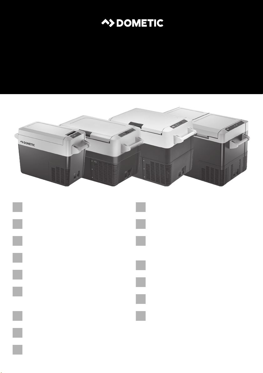
3Scope of delivery
Item
(fig. 1, page 3)
1 1 Cooler
2 1 Connection cable for DC connection
3 1 Connection cable for AC connection
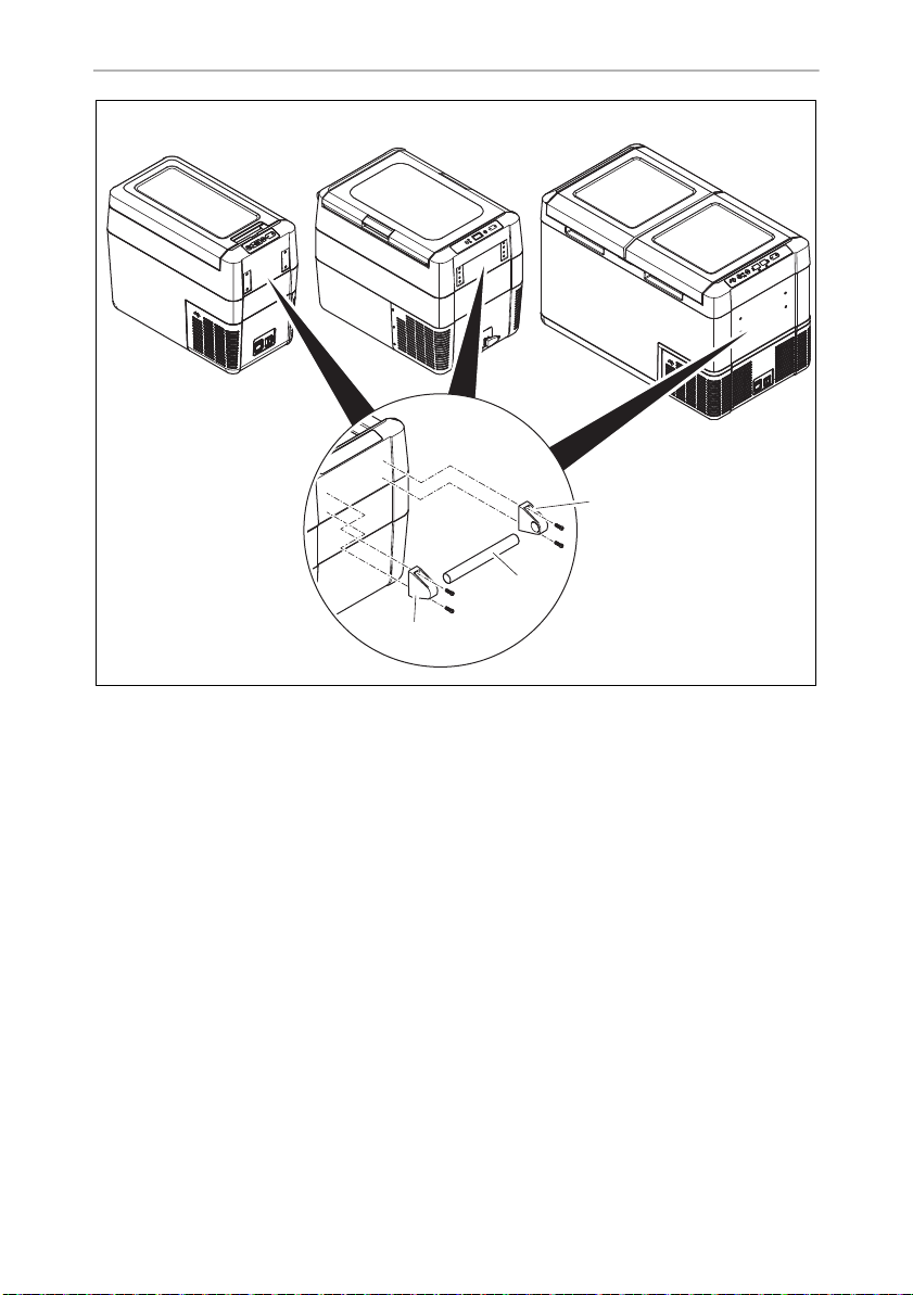
4 2 Carry handle, consisting of:
– 1 Operating manual
14
Quantity Description
•2 holders
•1 handle
• 4 fastening screws
• 1 allen wrench

EN
CFF20, CFF35, CFF45, CFF70DZ Intended use
4 Intended use
The cooling box is suitable for cooling food. The cooling box is also suitable for use
on vehicles. The cooling box is designed to be operated from a DC power supply
socket of a vehicle or from an AC power supply.
The cooling box is suitable for camping use.
The cooling box is not suitable for:
• storage of corrosive, caustic or solvent-containing substances
• freezing of food
This cooling box is not intended to be used as a built-in appliance.
This cooling box is only suitable for the intended purpose and application in accor-
dance with these instructions.
This manual provides information that is necessary for proper installation and/or
operation of the cooling box. Poor installation and/or improper operating or
maintenance will result in unsatisfactory performance and a possible failure.
The manufacturer accepts no liability for any injury or damage to the product
resulting from:
• Incorrect assembly or connection, including excess voltage
• Incorrect maintenance or use of spare parts other than original spare parts
provided by the manufacturer
• Alterations to the product without express permission from the manufacturer
• Use for purposes other than those described in this manual
Dometic reserves the right to change product appearance and product
specifications.
5 Function description
A low maintenance refrigerant circuit with compressor provides the cooling. The
generous insulation and powerful compressor ensure efficient and fast cooling.
The cooler is portable.
The cooler can withstand a short-term inclination of 30°, for example on boats.
15
EN
Function description CFF20, CFF35, CFF45, CFF70DZ
5.1 Scope of functions
• Power supply with priority circuit for connecting to the AC mains
• Three-level battery monitor to protect the vehicle battery
switches off automatically at low battery voltage
• Display with temperature gauge in °C and °F
• Temperature setting: With two buttons in steps of 1 °C (2 °F)
• Display dimming function with 3 brightness levels
• Removable wire basket (CFF35, CFF45, CFF 70DZ only)
• Removable carrying handles
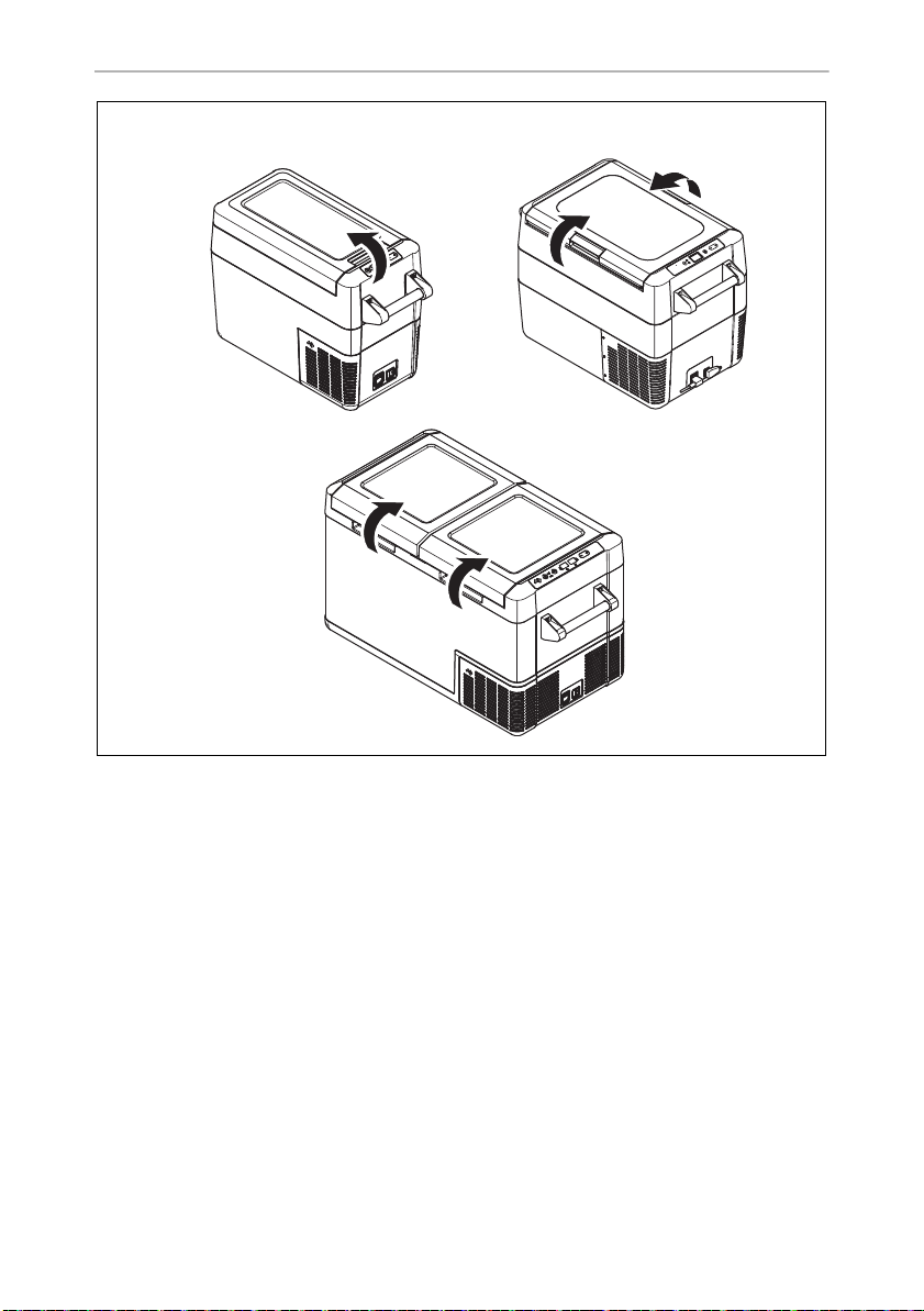
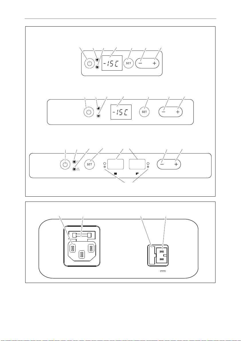
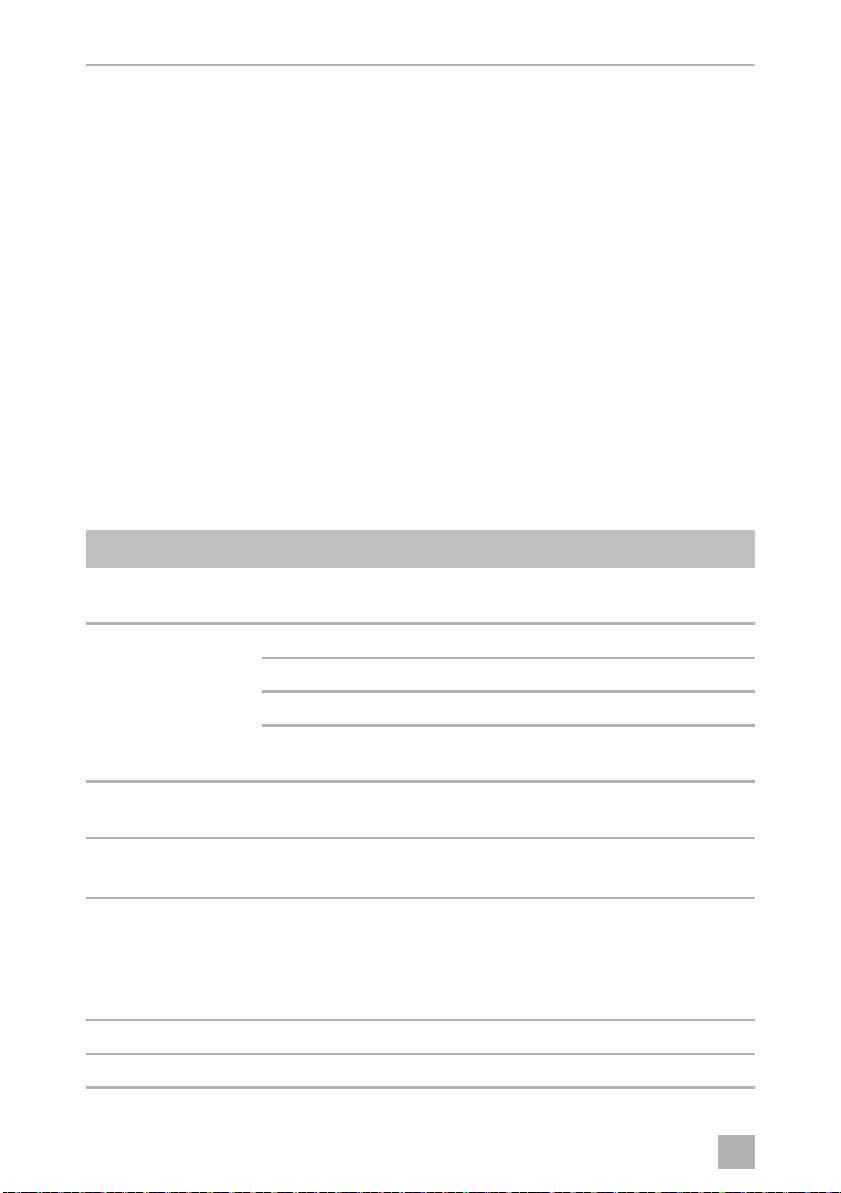
5.2 Operating and display elements
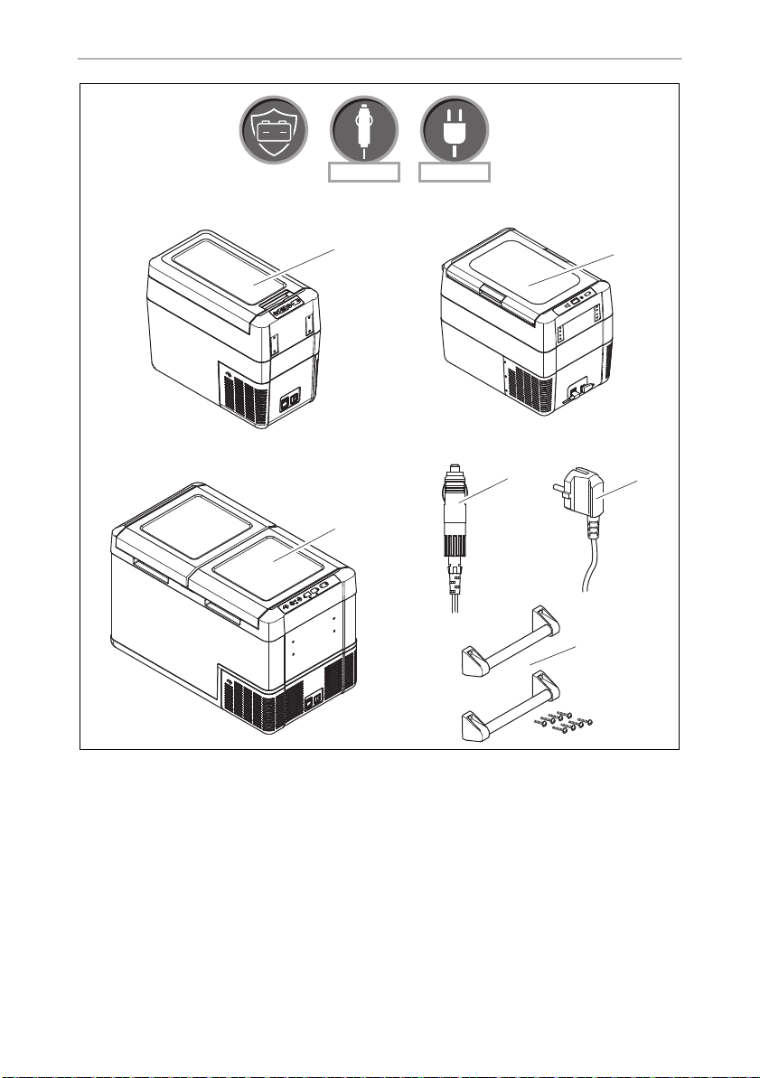
Lid latches (fig. 2, page 4)
Operating panel (fig. 3, page 5)
Item Description Explanation
1ON
OFF
2
POWER
3 ERROR LED flashes red: Device is switched on but not ready
4 – Display, shows the information
5 SET Selects the input mode
6 DOWN – Press once to decrease the value
7 UP + Press once to increase the value
“P”
Switches the cooler on or off when the button is pressed for
between one and two seconds
Status indication
LED lights up green: Compressor is on
LED lights up orange: Compressor is off
LED flashes orange: Display switched off automatically due
to low battery voltage
for operation
CFF70DZ only: There‘s one display per zone
– Temperature setting
– Celsius or Fahrenheit display
– Set battery monitor
– Set brightness of display
16

EN
CFF20, CFF35, CFF45, CFF70DZ Operation
Item Description Explanation
8 CFF70DZ only: Status indication: LED lights up blue when the
compartment is cooling
Connection sockets (fig. 4, page 5)
Item Description
1 Connection socket AC voltage supply
2 AC fuse holder
3 DC fuse cover
4 Connection socket DC voltage supply
6Operation
To avoid food waste, note the following:
• Keep temperature fluctuation as low as possible. Only open the cooling box as
often and for as long as necessary. Store the foodstuff in such a way that the air
can still circulate well.
• Adjust the temperature to the quantity and type of the foodstuff.
• Foodstuff can easily absorb or release odor or taste. Always store foodstuff
covered or in closed containers/bottles.
6.1 Before initial use
NOTE
I
Mounting the handles (fig. 5, page 6)
The handles are enclosed unassembled. If you wish to attach the handles, proceed
as follows:
➤ Assemble a handle by putting two holders (1) and a handle (2) together.
➤ Fasten the holders with the enclosed screws in the holes provided.
Before starting your new cooler for the first time, you should clean it
inside and outside with a damp cloth for hygienic reasons (please also
refer to the chapter “Cleaning and maintenance” on page 26).
17

EN
Operation CFF20, CFF35, CFF45, CFF70DZ
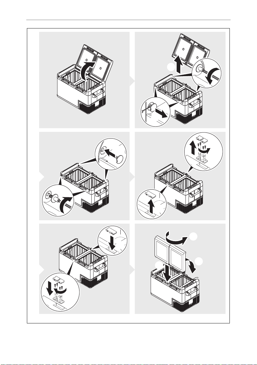
Reversing the lid opening
➤ CFF70DZ: To reverse the lid opening, proceed as shown (fig. 6, page 7).
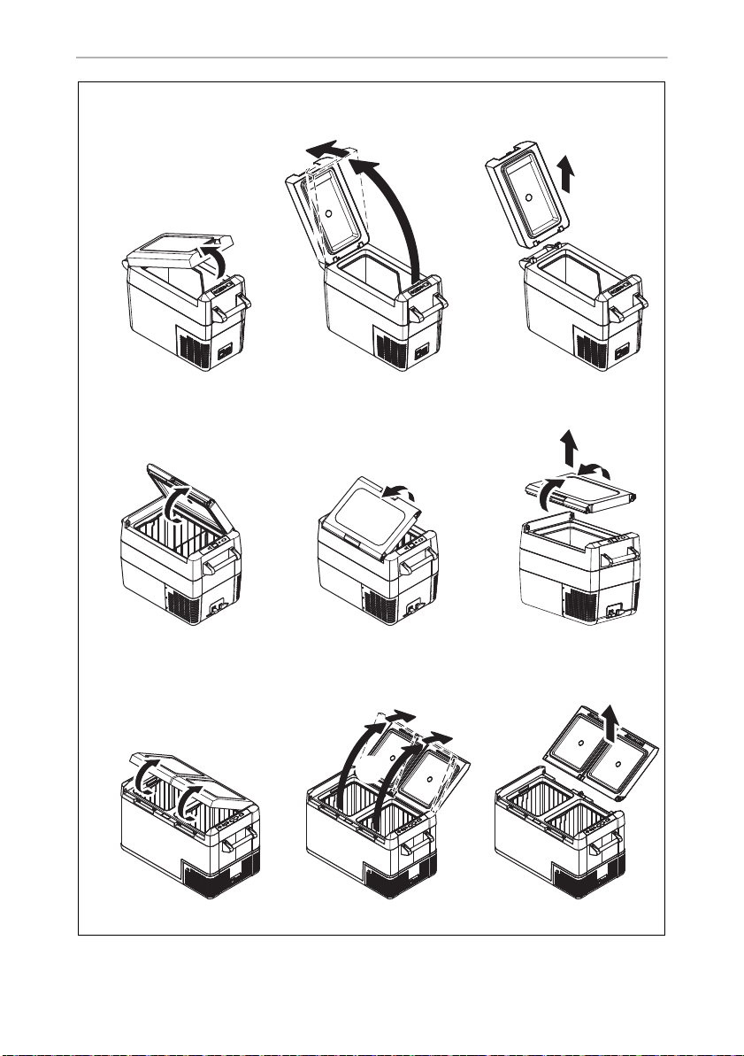
Opening or removing the lid (fig. 7, page 8)
➤ To open the lid, unlatch (A).
CFF35, CFF45: The lid can be opened from either side.
➤ CFF35, CFF45: To remove the lid, unlatch both sides at the same time (B).
CFF20, CFF70DZ: To remove the lid, push the lid beyond the lid stop
position (B).
Lid stop position (fig. 8, page 9)
The lid has a built-in stop position (A). Do not force the lid past the built-in stop (B).
NOTICE! DAMAGE HAZARD
A
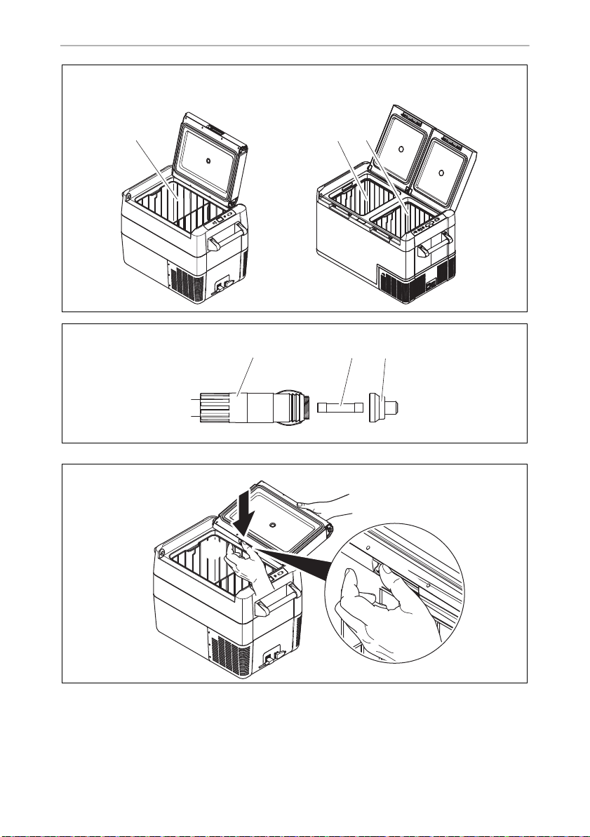
Removing the basket (fig. 9, page 9)
A
CFF35, CFF45: If the lid has been forced too far, follow the steps
described in the chapter “The lid has been forced past the built-in stop
(CFF35, CFF45 only)” on page 28.
NOTICE! DAMAGE HAZARD!
Removing the basket with the lid open may scratch the lid and deform
the basket. We recommend to remove the lid before removing the
basket.
Selecting the temperature units
Temperature display units can be switched between Celsius and Fahrenheit as
follows:
➤ Switch on the cooler.
➤ CFF20, CFF35, CFF45: Press the “SET” button (fig. 3 5, page 5) twice.
CFF70DZ: Press the “SET” button (fig. 3 5, page 5) three times.
➤ Use the “UP +” (fig. 3 7, page 5) or “DOWN –” (fig. 3 6, page 5) buttons to
select Celsius or Fahrenheit.
✔ The selected temperature unit then appears in the display for a few seconds. The
display flashes several times before it returns to the current temperature.
18

EN
CFF20, CFF35, CFF45, CFF70DZ Operation
6.2 Saving energy
• Choose a well ventilated location which is protected from direct sunlight.
• Allow warm food to cool down first before placing it in the cooling device to
keep cool.
• Do not open the cooling device more often than necessary.
• Do not leave the cooling device open for longer than necessary.
• If the cooler has a basket: For optimal energy consumption, position the basket
according to its position on delivery.
• On a regularly basis, make sure the lid seal still fits properly.
• Defrost the cooler once a layer of ice forms.
• Avoid unnecessarily low temperatures.
6.3 Connecting the cooler
Connecting to a battery (vehicle or boat)
The cooler can be operated with 12 V or 24 V
NOTICE! DAMAGE HAZARD
A
For safety reasons the cooler is equipped with an electronic system to prevent
polarity reversal. This protects the cooler against short-circuiting when connecting to
a battery.
Using the fused DC plug
A
➤ Plug the DC connection cable (fig. 1 2, page 3) into the DC voltage socket of
the cooler (fig. 4 4, page 5).
➤ Connect the connection cable to a DC power outlet.
Disconnect the cooler and other consumer units from the battery before
you connect the battery to a quick charging device.
Overvoltage can damage the electronics of the device.
NOTICE! DAMAGE HAZARD
For protection of the device the DC cable supplied includes a fuse inside
the plug. Do not remove the fused DC plug.
Only use the DC cable supplied.
g.
19

EN
Operation CFF20, CFF35, CFF45, CFF70DZ
Connecting to an AC power supply
DANGER! ELECTROCUTION HAZARD
D
The coolers have an integrated multi-voltage power supply with priority circuit for
connecting to an AC voltage source. The priority circuit automatically switches the
cooler to AC operation if the device is connected to an AC power supply, even if the
DC connection cable is still attached.
When switching between the AC power supply and the battery supply, the red LED
may light up briefly.
➤ Plug the AC connection cable (fig. 1 3, page 3) into the AC voltage socket of
the cooler (fig. 4 1,page 5).
➤ Connect the connection cable to an AC power outlet.
Failure to obey these warnings will result in death or serious injury.
• Never handle plugs and switches with wet hands or if you are standing on a wet surface.
• If you are operating your cooler on board a boat from a AC power
supply, you must install a residual current circuit breaker between the
AC power supply and the cooler.
Seek advice from a trained technician.
6.4 Using the battery monitor
The device is equipped with a multi-level battery monitor that protects your vehicle
battery against excessive discharging when the device is connected to the on-board
DC supply.
If the cooler is operated when the vehicle ignition is switched off, the cooler switches
off automatically as soon as the supply voltage falls below a set level. The cooler will
switch back on once the battery has been recharged to the restart voltage level.
NOTICE! DAMAGE HAZARD
A
When switched off by the battery monitor, the battery will no longer be
fully charged. Avoid starting repeatedly or operating current consumers
without longer charging phases. Ensure that the battery is recharged.
20

EN
CFF20, CFF35, CFF45, CFF70DZ Operation
In “HIGH” mode, the battery monitor responds faster than at the levels “LOW” and
“MED” (see the following table).
Battery monitor mode LOW MED HIGH
Switch-off voltage at 12 V
Restart-voltage at 12 V
Switch-off voltage at 24 V
Restart voltage at 24 V
The battery monitor mode can be selected as follows:
➤ Switch on the cooler.
➤ Press the “SET” button (fig. 3 5, page 5):
– CFF 20, CFF35, CFF45: Three times.
– CFF 70DZ: Four times.
➤ Use the “UP +” (fig. 3 7, page 5) or “DOWN –” (fig. 3 6, page 5) buttons to
select the battery monitor mode.
✔ Display will be as follows:
Lo (LOW), ΠEd (MED), Hi (HIGH)
✔ The selected mode then appears in the display for a few seconds. The display
flashes several times before it returns to the current temperature.
NOTE
I
When the cooler is supplied by the starter battery, select the battery
monitor mode “HIGH”. If the cooler is connected to a supply battery,
the battery monitor mode “LOW” will suffice.
10.1 V 11.2 V 11.8 V
11.4 V 12.2 V 12.6 V
21.5 V 24.1 V 24.6 V
23.0 V 25.3 V 26.2 V
6.5 Using the cooler
NOTICE! OVERHEATING HAZARD
A
Ensure at all times that there is sufficient ventilation so that the heat that
generated during operation can dissipate. Ensure that the ventilation
slots are not covered. Make sure that the device is sufficiently far away
from walls and other objects so that the air can circulate.
21

EN
Operation CFF20, CFF35, CFF45, CFF70DZ
➤ Place the cooler on a firm foundation.
Make sure that the ventilation slots are not covered and that the heated air can
dissipate. We recommend keeping a gap of at least 50 mm around ventilation
holes.
NOTICE! DAMAGE HAZARD
A
➤ Connect the cooler (see chapter “Connecting the cooler” on page 19).
A
➤ Press the “ON/OFF” button (fig. 3 1, page 5) for between one and two
seconds.
✔ The LED “P” lights up (fig. 3 2, page 5).
✔ The display (fig. 3 4, page 5) switches on and shows the current temperature.
✔ The cooler starts cooling the interior.
I
Place the cooler as shown (fig. 1, page 3). If you operate the cooler in
a different orientation it can be damaged.
NOTICE! EXCESSIVELY LOW TEMPERATURE HAZARD
Ensure that the only those objects are placed in the cooler that are
intended to be cooled at the selected temperature.
NOTE
When operating from a battery, the display switches off automatically if
the battery voltage is low. The LED “P” flashes orange.
Latching the cooler lid
➤ Close the lid.
➤ Press the latch (fig. 2, page 4) down, until it latches in place audibly.
NOTE
I
22
CFF35, CFF45: When latching the lid, ensure that both latch side pins
are fully engaged to ensure a good lid seal. One latch may engage
slightly before the other.
If the lid is not closed equally at both sides, press until a second click is
heard.

EN
CFF20, CFF35, CFF45, CFF70DZ Operation
6.6 Setting the temperature
CFF20, CFF35, CFF 45
➤ Press the “SET” button (fig. 3 5, page 5) once.
➤ Use the “UP +” (fig. 3 7, page 5) and “DOWN –” (fig. 3 6, page 5) buttons to
select the cooling temperature.
✔ The cooling temperature appears in the display for a few seconds. The display
flashes several times and then the current temperature is displayed again.
CFF70DZ
➤ Press the “SET” button (fig. 3 5, page 5):
– once for the large compartment
– twice for the small compartment
✔ The chosen compartment‘s display blinks.
➤ Use the “UP +” (fig. 3 7, page 5) and “DOWN –” (fig. 3 6, page 5) buttons to
select the cooling temperature.
Each compartment can be set to work as a refrigerator or a freezer compartment.
✔ The cooling temperature appears in the chosen compartment‘s display for a few
seconds. The display flashes several times and then the current temperature is
displayed again.
6.7 Switching a compartment off or on (CFF70DZ)
If only one compartment is required, the other compartment can be switched off to
save energy.
Switching off a compartment
If the display of the compartment shows a temperature, you can switch off the
compartment as follows:
➤ Press the “SET” button (fig. 3 5, page 5):
– Once for the large compartment
– Twice for the small compartment
✔ The display of the respective compartment blinks.
➤ Press the “ON/OFF” button (fig. 3 1, page 5).
✔ “OFF” flashes for five seconds on the display of the respective cooling
compartment, then “OFF” is displayed.
23

EN
Operation CFF20, CFF35, CFF45, CFF70DZ
Switching on a compartment
If the display of the compartment shows “OFF”, you can switch on the compartment
as follows:
➤ Press the “SET” button (fig. 3 5, page 5):
– Once for the large compartment
– Twice for the small compartment
✔ The display of the respective compartment blinks.
➤ Press the “ON/OFF” button (fig. 3 1, page 5).
✔ The cooling temperature appears in the display for a few seconds. The display
flashes several times and then the current temperature is displayed.
6.8 Setting the display brightness
The display brightness can be dimmed for low ambient light conditions. To set the
dimming level of the display proceed as follows:
➤ Switch on the cooler.
➤ Press the “SET” button (fig. 3 5, page 5):
– CFF 20, CFF35, CFF45: Four times.
– CFF 70DZ: Five times.
➤ Use the “UP +” (fig. 3 7, page 5) or “DOWN –” (fig. 3 6, page 5) buttons to
set the brightness of the display.
✔ Display will be as follows:
d0 (default), d1 (medium), d2 (dark)
✔ The display shows the set mode for several seconds. The display flashes twice
before it returns to the current temperature.
NOTE
I
• The factory setting of brightness of the display is d0 (default).
• If a fault occurs, the brightness automatically reverts to brightness d0
(default). After troubleshooting the set brightness is reactivated.
6.9 Switching off the cooler
➤ Empty the cooler.
➤ Switch the cooler off.
➤ Pull out the connection cable.
24

EN
CFF20, CFF35, CFF45, CFF70DZ Operation
If you do not want to use the cooler for a longer period of time:
➤ Leave the lid slightly open. This prevents odor build-up.
6.10 Defrosting the cooler
Humidity can form frost in the interior of the cooling device or on the evaporator. This
reduces the cooling capacity.
NOTICE! DAMAGE HAZARD
A
To defrost the cooler, proceed as follows:
➤ Take out the contents of the cooler.
➤ If necessary, place them in another cooling device to keep them cool.
➤ Switch off the device.
➤ Leave the lid open.
➤ Wipe off the defrosted water.
Never use hard or pointed tools to remove ice or to loosen objects
which have frozen in place.
6.11 Replacing the AC fuse
DANGER! ELECTROCUTION HAZARD
D
➤ Disconnect the power supply to the device.
➤ Remove the connection cable.
➤ Pry out the fuse insert (fig. 4 2, page 5) with a screwdriver.
➤ Replace the defective glass fuse with a new one that has the same type and rating
(4 A, 250 V).
➤ Press the fuse insert back into the housing.
➤ Reconnect the power supply to the device.
Failure to obey this warning will result in death or serious injury.
Disconnect the power supply and the connection cable before you
replace the device fuse.
25

EN
Cleaning and maintenance CFF20, CFF35, CFF45, CFF70DZ
6.12 Replacing the device DC Fuse
➤ Disconnect the power supply to the device.
➤ Pry out the fuse cover (fig. 4 3, page 5) to access the fuse.
➤ Reverse the fuse cover and use the hook to remove the fuse.
➤ Replace the defective fuse with a new fuse of the same type (Automotive Stan-
dard blade fuse, 10 A).
➤ Re-fit the fuse cover.
➤ Reconnect the power supply to the device.
6.13 Replacing the DC plug fuse (fig. a, page 10)
➤ Unscrew the contact pin housing (3) from the plug (1).
➤ Replace the defective fuse (2) with a new fuse of the same type and rating (3AG,
Fast Acting, 10 A).
➤ Re-assemble the plug in reverse order.
6.14 Replacing the light PCB
NOTICE! Damage hazard
A
The lamp can only be replaced by the manufacturer, a service agent or
similarly qualified person to avoid hazard.
7 Cleaning and maintenance
WARNING! ELECTROCUTION HAZARD
!
A
26
Failure to obey this warning could result in death or serious injury.
Always disconnect the device from the power supply before you clean
and service it.
NOTICE! Damage hazard
• Never clean the cooler under running water or in dish water.
• Do not use abrasive cleaning agents or hard objects during cleaning
as these can damage the cooler.

EN
CFF20, CFF35, CFF45, CFF70DZ Troubleshooting
➤ Occasionally clean the device interior and exterior with a damp cloth.
➤ Make sure that the air inlet and outlet vents on the device are free of any dust and
dirt, so that heat can be released and the device is not damaged.
8 Troubleshooting
Fault Possible cause Suggested remedy
Device does not
function, LED does
not glow.
The device does not
cool (plug is inserted,
“POWER” LED is lit).
The device does not
cool (plug is inserted,
“POWER” LED flashes
orange, display is
switched off).
No voltage present in
the connected power
outlet.
One of the device fuses
is defective.
The integrated mains
adapter is defective.
Defective compressor. This can only be repaired by an
Battery monitor is set
too high.
Battery voltage is too
low.
Plugged in DC power outlet: In most
vehicles the ignition must be turned on
before power will be supplied to the DC
power outlet.
Plugged in AC power outlet: Try using
another plug outlet.
Replace the defective device fuse, see
chapter “Replacing the AC fuse” on
page 25 or chapter “Replacing the
device DC Fuse” on page 26.
This can only be repaired by an
authorised repair center.
authorised repair center.
Select a lower battery monitor setting.
Test the battery and charge it as needed.
27

EN
Troubleshooting CFF20, CFF 35, CFF45, CFF70DZ
Fault Possible cause Suggested remedy
When operating from
the DC outlet:
The ignition is on
and the device is not
working and the LED
is not lit.
The display shows an
error message (e.g.
“Err1”) and the appliance does not cool.
The DC outlet is dirty.
This results in a poor
electrical contact.
The fuse of the DC plug
has blown.
The device DC fuse has
blown.
The vehicle fuse has
blown.
The appliance has
switched off due to an
internal fault.
If the plug of your cooler becomes very
warm in the DC outlet, either the DC
outlet must be cleaned or the plug has
not been assembled correctly.
Replace the fuse in the DC plug, see
chapter “Replacing the DC plug fuse
(fig. a, page 10)” on page 26.
Replace the defective fuse, see chapter
“Replacing the device DC Fuse” on
page 26.
Replace the vehicle’s DC outlet fuse.
Please refer to your vehicle’s operating
manual.
This can only be repaired by an
authorised repair center.
8.1 The lid has been forced past the built-in stop (CFF35, CFF45 only)
Proceed as follows (fig. b, page 10):
➤ Support the lid with one hand (A).
➤ Hold the latch down with the other hand (B).
CAUTION! HEALTH HAZARD
!
A
➤ Close the lid as far as possible without pinching your thumb, while still holding
the latch down, to keep it from breaking.
✔ The lid should now be approximately at the angle shown (fig. b, page 10).
➤ Remove the hand from the latch (B), and continue closing the lid all the way.
Failure to obey this caution could result in minor or moderate injury.
Beware pinching your thumb while closing the lid.
NOTICE! DAMAGE HAZARD!
Failure to observe this instruction can cause the lid to break off.
28

EN
CFF20, CFF35, CFF45, CFF70DZ Warranty
NOTE
I
The hinges may release from the correct position during the final closing
action. Reposition the lid as follows:
➤ Operate the latches on both sides of the lid simultaneously.
➤ Lift and reposition the lid.
9Warranty
The statutory warranty period applies. If the product is defective, please contact the
manufacturer's branch in your country (see dometic.com/dealer) or your retailer.
For repair and warranty processing, please include the following documents when
you send in the device:
• A copy of the receipt with purchasing date
• A reason for the claim or description of the fault
10 Disposal
➤ Place the packaging material in the appropriate recycling waste bins wherever
possible.
M
If you wish to finally dispose of the product, ask your local recycling centre
or specialist dealer for details about how to do this in accordance with the
applicable disposal regulations.
29
EN
Technical data CFF20, CFF35, CFF45, CFF70DZ
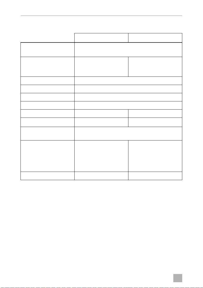
11 Technical data
CFF20 CFF35
Connection voltage: 12/24 Vg
100 to 240 Vw
Rated current: 12 Vg: 4.8 A
24 Vg: 2.8 A
240 Vw: 0.3 A
Cooling capacity: +20 °C to –18 °C (+68 °F to 0 °F)
Climate class: N, T
Ambient temperature: +16 °C to +43 °C (+60 °F to +110 °F)
Refrigerant: R134a
Refrigerant volume: 28 g 34 g
equivalent: 0.040 t 0.049 t
CO
2
Global warming potential
(GWP):
Dimensions
(WxHxD) (including
handles):
(W x H x D) (with handles
removed):
Weight: 10.5 kg 17.2 kg
283 x 430 x 660 mm
283 x 430 x 533 mm
1430
12 Vg: 7.8 A
24 Vg: 3.5 A
240 Vw: 0.4 A
715 x 407 x 398 mm
590 x 500 x 443 mm
30
 Loading...