

ENDEFRESPTITNLDASV
NOFIRUPLSKCSHU
DRIVING SUPPORT
PERFECTVIEW
CAM45
Rear View Video Camera
Installation and Operating Manual . . . . . . 9
Rückfahrvideokamera
Montage- und Bedienungsanleitung . . . 20
Caméra vidéo de recul
Instructions de montage et de service . . 31
Cámara de vídeo de marcha atrás
Instrucciones de montaje y de uso . . . . . 42
Câmara de marcha-atrás
Instruções de montagem e manual de
instruções . . . . . . . . . . . . . . . . . . . . . . . . . 53
Videocamera per la retromarcia
Istruzioni di montaggio e d’uso . . . . . . . .63
Achteruitrijvideocamera
Montagehandleiding en
gebruiksaanwijzing. . . . . . . . . . . . . . . . . . 74
Bakvideokamera
Monterings- og betjeningsvejledning. . . 85
Backningsvideokamera
Monterings- och bruksanvisning . . . . . . . 95
Ryggevideokamera
Monterings- og bruksanvisning . . . . . . .105
Peruutusvideokamera
Asennus- ja käyttöohje. . . . . . . . . . . . . . .115
Видеокамера заднего вида
Инструкция по монтажу
и эксплуатации. . . . . . . . . . . . . . . . . . . . 126
Kamera cofania
Instrukcja montażu i obsługi . . . . . . . . . 137
Cúvacia kamera
Návod na montáž a uvedenie
do prevádzky . . . . . . . . . . . . . . . . . . . . . 148
Couvací kamera
Návod k montáži a obsluze . . . . . . . . . . 158
To l a t ó k a m e r a
Szerelési és használati útmutató . . . . . . 168

CAM45
1 2
3
4
7 8 9
5
6
10 11 12
1
3
CAM45
2
3
4
5
6
7
4
1
3 4
2
8
3
2
1
9
CAM45
5
CAM45
90°
0
a
1.
2.
b
c
d
e
6
~50°
f
AB
1.
2.
1.
g
h
A
B
i
CAM45
7
1.
2.
j
CAM45
8

CAM45
EN
Please read this instruction manual carefully before installati on and first use, and store
it in a safe place. If you pass on the product to another person, hand over this instruction manual along with it.
Table of contents
1 Explanation of symbols. . . . . . . . . . . . . . . . . . . . . . . . . . . . . . . . . . . . . . . . . . . . . . . . . . . . . . 10
2 Safety and installation instructions . . . . . . . . . . . . . . . . . . . . . . . . . . . . . . . . . . . . . . . . . . . . . 10
3 Scope of delivery . . . . . . . . . . . . . . . . . . . . . . . . . . . . . . . . . . . . . . . . . . . . . . . . . . . . . . . . . . 12
4 Intended use . . . . . . . . . . . . . . . . . . . . . . . . . . . . . . . . . . . . . . . . . . . . . . . . . . . . . . . . . . . . . . 12
5 Technical description . . . . . . . . . . . . . . . . . . . . . . . . . . . . . . . . . . . . . . . . . . . . . . . . . . . . . . . 13
6 Information on electrical connection . . . . . . . . . . . . . . . . . . . . . . . . . . . . . . . . . . . . . . . . . . . 13
7 Fitting the camera . . . . . . . . . . . . . . . . . . . . . . . . . . . . . . . . . . . . . . . . . . . . . . . . . . . . . . . . . . 14
8 Cleaning and caring for the camera . . . . . . . . . . . . . . . . . . . . . . . . . . . . . . . . . . . . . . . . . . . . 17
9 Warranty . . . . . . . . . . . . . . . . . . . . . . . . . . . . . . . . . . . . . . . . . . . . . . . . . . . . . . . . . . . . . . . . . 18
10 Disposal. . . . . . . . . . . . . . . . . . . . . . . . . . . . . . . . . . . . . . . . . . . . . . . . . . . . . . . . . . . . . . . . . . 18
11 Technical data . . . . . . . . . . . . . . . . . . . . . . . . . . . . . . . . . . . . . . . . . . . . . . . . . . . . . . . . . . . . . 19
9

Explanation of symbols CAM45
EN
1 Explanation of symbols
WARN ING !
!
!
A
I
Safety instruction: Failure to observe this instruction can cause fatal or serious injury.
CAUTION!
Safety instruction: Failure to observe this instruction can lead to injury.
NOTICE!
Failure to observe this instruction can cause material damage and impair the function
of the product.
NOTE
Supplementary information for operating the product.
2 Safety and installation instructions
Please observe the prescribed safety instructions and stipulations from the vehicle
manufacturer and service workshops.
The manufacturer accepts no liability for damage in the following cases:
•
Faulty assembly or conn ection
•
Damage to the product resulting from mechanical influences and excess voltage
•
Alterations to the product without express permission from the manufacturer
•
Use for purposes other than those described in the operating manual
Please note the following:
•
To prevent the risk of short circuits, always disconnect the negative terminal of the vehicle's
electrical system before working on it.
If the vehicle has an additional battery, its negative terminal should also be disconnected.
•
Inadequate supply cable connections could result in short circuits, causing:
–Cable fires
– The airbag being triggered
– Damage to electronic control equipment
– Electrical malfunctions (indicators, brake light, horn, ignition, lights)
•
When working on the following cables, only use insulated cable terminals, plugs and flat
sockets:
– 30 (direct supply from positive battery terminal)
–15 (connected positive terminal, behind the battery)
– 31 (return cable from the battery, earth)
– 58 (reversing light)
Do not use porcelain wire connectors.
10

CAM45 Safety and installation instructions
EN
•
Use a crimping tool (fig. 1 10, page 3) to connect the cables.
•
Screw the cable when connecting cable 31 (earth).
– Screw on the cable using a cable terminal and serrated washer to one of the v ehicle's earth
bolts or
– screw the cable to the bodywork using a cable terminal and a self-tapping screw.
Make sure there is a good earth connection.
If you disconnect the negative terminal of the battery, all data stored in the volatile memories will
be lost.
•
The following data must be reset, depending on the vehicle equipment options:
–Radio code
– Vehicle clock
–Timer
– On-board computer
– Seat position
You can find instructions for making these settings in the operating manual.
Observe the following installation instructions:
•
Secure the parts of the camera which are installed in the vehicle in such a way that they cannot
become loose under any circumstances (sudden braking, accidents) and cause injuries to the
occupants of the vehicle.
•
Secure any parts of the system concealed by the bodywork in such a manner that they cannot
be come loose or damage other parts or cables, or impair vehicle functions (steering, pedals,
etc.).
•
To prevent damage when drilling, make sure there is sufficient space on the other side for the
drill head to come out (fig. 2, page 4).
•
Deburr all drill holes and treat them with a rust-protection agent.
•
Always follow the safety instructions of the vehicle manufacturer.
Some work (e.g. on retention systems such as the AIRBAG etc.) may only be performed by
qualified specialists.
Observe the following instructions when working with electrical parts:
•
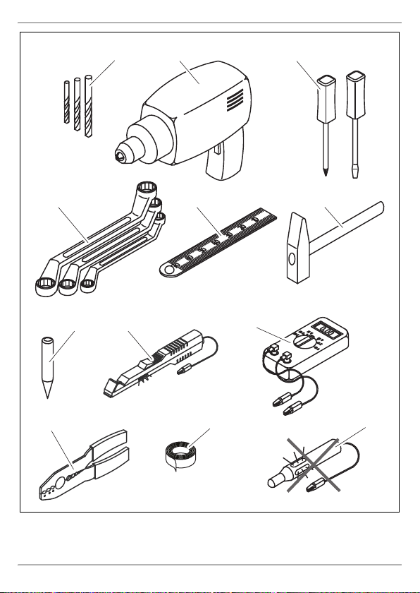
When testing the voltage in electrical cables, only use a diode test lamp (fig. 1 8, page 3) or
a voltmeter (fig. 1 9, page 3).
Test lamps with a bulb (fig. 1 12, page 3) consume voltages which are too high and can
damage the vehicle's electronic system.
•
When making electrical connections, (fig. 3, page 4), ensure that:
– they are not kinked or twisted
– they do not rub on edges
– they are not laid in sharp-edged ducts without protection.
•
Insulate all connections.
11

Scope of delivery CAM45
EN
•
Secure the cables against mechanical wear by using cable binders or insulating tape,
for example on existing cables.
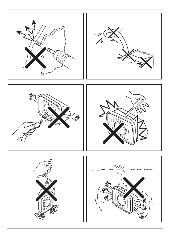
The camera is watertight. However, the seals on the camera cannot withstand a high-pressure
cleaner (fig. 4, page 4). Therefore, y ou should observe the following instructions when handling
the camera:
•
People (including children) whose physical, sensory or mental capacities or whose lack of
experience or knowledge prevent them from using this produc t safely should not use it without
the supervision or instruction of a responsible person.
•
Do not open the camera, as this impairs the leak tightness and the function of the camera
(fig. 5, page 4).
•
Do not pull at the cables , as this impairs the tightness and the function of the camera (fig. 6,
page 4).
•
The camera is not suitable for use under water (fig. 7, page 4)!
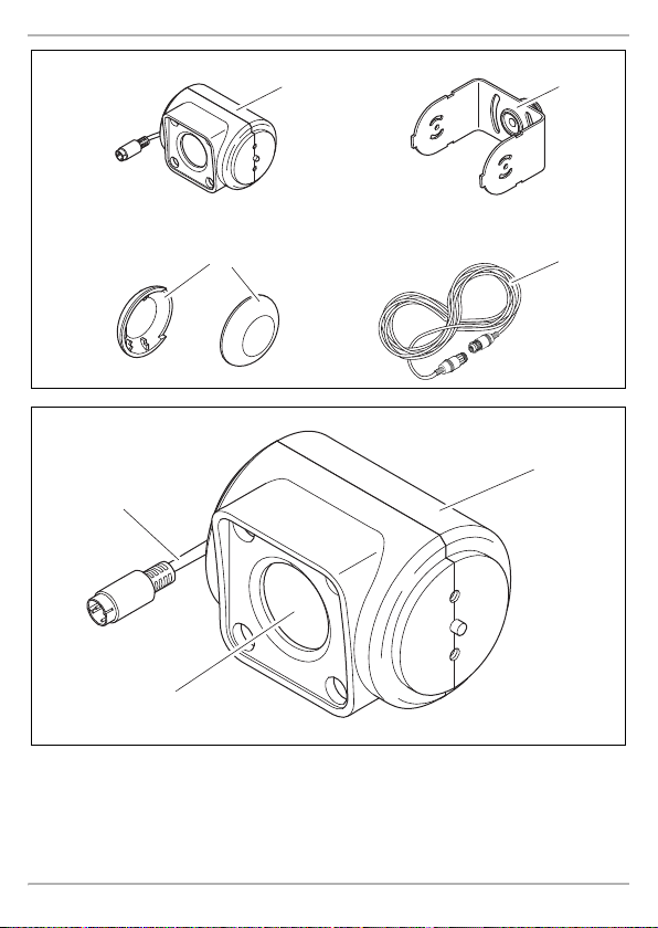
3Scope of delivery
No. in
fig. 8, page 5
1 1 Camera 9600000523
21Camera bracket
32Side cover –
4 1 System cable 9102200141
–1Fastening material –
– 1 Installation and operating manual –
Quantity Description Ref. no.
9600000571
with bushing sleeve
4Intended use
The CAM 45 camera (ref. no. 9600000523) is designed primarily for use in vehicles. It can be used
in video systems to observe the space around the v ehicle from the driver's seat when, for example
manoeuvring or parking.
WARN ING !
!
Danger of personal injury by vehicle.
Reversing video systems are designed merely as an additional aid for reversing,
however this does not relieve you of the duty to take proper care when
reversing.
12

CAM45 Technical description
EN
5 Technical description
The camera with integrated microphone, which is encased in an aluminium housing, transmits
image and sound to a monitor via a cable. The infrared LEDs improve night vision.
The camera transmits the image as if you were looking in the rear-view mirror.
The camera consists of the following elements:
No. in
fig. 9, page 5
16-pin connection cable
2 Infrared LEDs
3 Microphone (rear side)
Description
6 Information on electrical connection
6.1 Laying cables
NOTICE! Beware of damage
•
A
Therefore, please observe the following instructions:
•
As far as possible, use o riginal ducts for laying the cables, or other suitable options such as
panelling edges, ventilation grilles or dummy plugs. If no openings are available, you must drill
holes for the cables. Check beforehand that there is sufficient space on the other side for the
drill head to emerge.
•
Wherever possible, lay cables inside the vehicle, as they are better protected there than
outside.
If you do need to lay a cable outside the vehicle, ensure that it is well fastened (use additional
cable ties, insulating tape etc.).
•
To prevent damage to the cables when laying them, ensure that they are far enough away from
hot or moving vehicle components (exhaust pipes, drive shafts, light systems, fans, heaters,
etc.). Use corrugated piping or other protective materials to protect against mechanical wear.
•
Screw on the plug connections for the connecting cables to protect them against water
penetration (fig. g, page 7).
When drilling holes, check beforehand that there is sufficient space on the other
side for the drill head to come out.
•
Cables and connections that are not properly installed will cause malfunctions or
damage to components. Correct installation of cables and connections ensures
lasting and trouble-free operation of the retrofitted components.
•
The cables may not be exposed for long periods to solvents such as benzene, since
solvents can damage the cable.
13

Fitting the camera CAM45
EN
•
When laying the cables (fig. 3, page 4), make sure:
– they are not kinked or twisted
– they do not rub on edges
– they are not routed in sharp-edged ducts without protection.
•
Attach the cables securely in the vehicles to prevent tripping hazards. This can be performed by
using cable binders, insulating tape or gluing in place with adhesives.
•
Protect every through-hole made in the bodywork against water penetration, e.g. by using a
cable with a sealant and by spraying the cable and the cable sleeve with sealant.
NOTE
I
Only start sealing through-holes when you have completed all installation work on the
camera and have laid the required cable lengths.
7 Fitting the camera
7.1 Too ls re qu ir ed
For installation and assembly, you will need the following tools:
•
Drill bit set (fig. 1 1, page 3)
•
Electric drill (fig. 1 2, page 3)
•
Screwdriver (fig. 1 3, page 3)
•
Set of ring or open-ended spanners (fig. 1 4, page 3)
•
Measuring ruler (fig. 1 5, page 3)
•
Hammer (fig. 1 6, page 3)
•
Centre punch (fig. 1 7, page 3)
To establish and test the electrical connection, the following tools are required:
•
Diode test lamp (fig. 1 8, page 3) or voltmeter (fig. 1 9, page 3)
•
Insulating tape (fig. 1 11, page 3)
•
Cable bushing sleeves (optional)
To fasten the cables you may require additional cable binders.
14

CAM45 Fitting the camera
EN
7.2 Fitting the camera
CAUTION!
!
I
Observe the following installation instructions:
•
•
•
•
•
•
I
To perform the installation, proceed as follows:
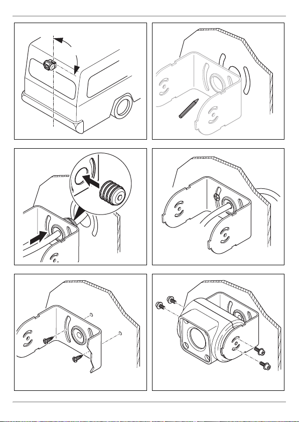
➤ Hold the camera at the chosen location and mark at least two different points for the drill holes
➤ Using a hammer and centre punch, gently pre-punch the previously marked points to prevent
Select a location for the camera and attach it firmly enough so that it cannot under any
circumstances fall off and injure bystanders (e.g. by being knocked off by branches
brushing over the roof of the vehicle).
NOTE
If installing the camera alters the vehicle height or the length specified in the vehicle
documents, your vehicle must be inspected by the appropriate authorities.
This authority must note any such changes your vehicle documents.
To provide a suitable viewing angle, the camera must be attached at a height of at least 2 m.
Ensure that you have a firm place from which to work when mounting the camera.
Make sure that the installation location of the camera is sufficiently firm (e.g. to prevent the
camera from being knocked down by branches that may brush the roof of the vehicle).
Mount the camera bracket horizontally and in the middle of the rear of the vehicle (fig. 0,
page 6).
The most secure type of attachment is with screws fitted through the body (not included in
scope of delivery). Please observe the following instructions:
– There must be sufficient space behind the chosen installation location to be able to carry
out the mounting procedure.
– Suitable measures must be taken to prevent water penetrating through any holes made
(e.g. by using screws and sealant and/or spraying the outer attachment parts with sealant).
– The location on the body where you wish to attach the camera must be rigid enough to
allow the camera to be tightly fastened.
Check beforehand that there is suffici ent space on the other side for the drill head to come out
(fig. 2, page 4).
If you are not sure about the location you have chosen, ask your vehicle manufacturer or dealer.
NOTE
We recommend greasing the threads of the bolts to prevent corrosion.
and the duct for the connection cable (fig. a, page 6).
the drill head from slipping off.
15

Fitting the camera CAM45
EN
Creating a through-hole for the camera connection cable (fig. b, page 6)
NOTE
I
A
➤ Drill a hole with a Ø 16 mm at the previously marked duct.
➤ Deburr all drill holes that have been made in the sheet metal and apply rust-protection.
Screw on camera using self-tapping screws (fig. c, page 6)
A
➤ Drill the holes, with a Ø of 4 mm, at each of the markings.
➤ Deburr all drill holes and apply rust-protection.
➤ Screw on the camera bracket using 5 x 20 mm self-tapping screws.
Fitting the camera
A
➤ Guide the camera cable into the vehicle interior.
➤ Slide the camera into the camera bracket.
➤ Fasten the camera loosely using the two screws M3 x 6 mm in the slots (fig. e, page 6).
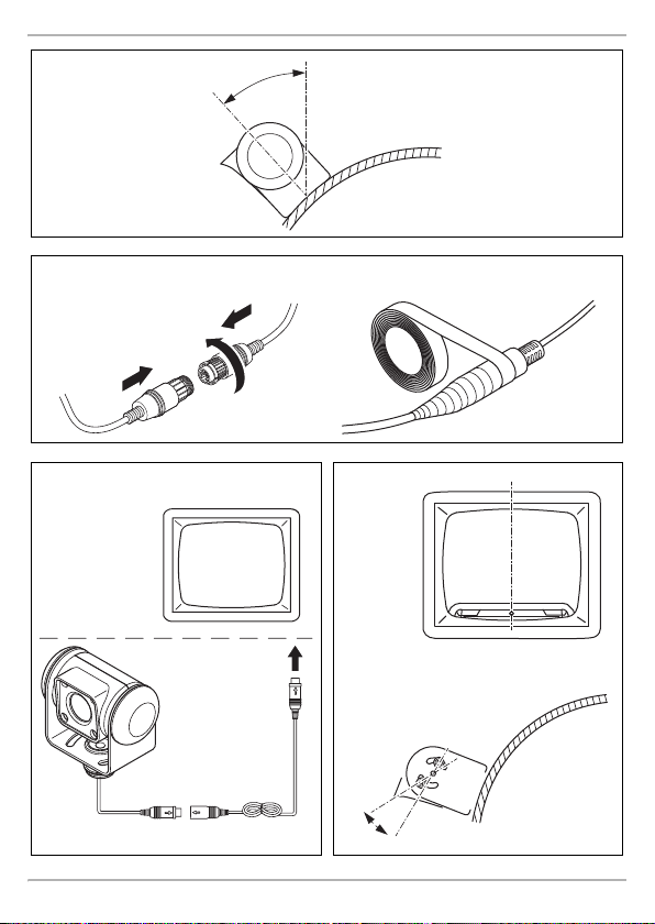
➤ Provisionally align the camera, so that the lens is at an angle of approx. 50° to the vertical axis
If possible, use available openings, such as ventilation grilles, to feed the connection
cables through. If there are no existing ducts, you must drill a hole of Ø 16 mm.
NOTICE! Beware of damage
Check beforehand that there is sufficient space on the other side for the drill head to
come out.
NOTICE! Beware of damage
Self-tapping screws may only be fastened to steel metal with a minimum thickness of
1.5 mm.
NOTICE! Beware of damage
Only use the screws supplied to mount the camera. Longer screws will damage the
camera.
of the vehicle (fig. f, page 7).
16

CAM45 Cleaning and caring for the camera
EN
Establishing the electrical connection for the camera
NOTE
•
I
➤ Insert the camera cable plug into the socket for the extension cable.
➤ Screw on the plug connection of the connecting cables to protect against water penetration
Aligning the camera
I
➤ Align the camera using the image on the monitor to help you:
➤ Check the function of the camera after you have connected it to a monitor.
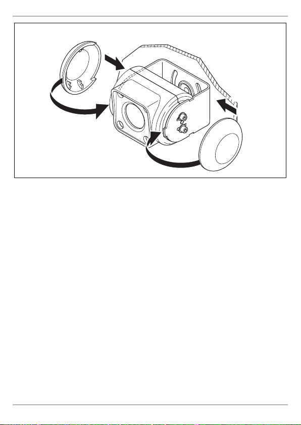
Fastening the camera
➤ Tighten the two fastening screws in the slots on the monitor bracket.
➤ Fit side covers into place (fig. j, page 8).
Lay the camera cable so that, should you need to remove the camera, you can
access the plug connection between the
camera and the extension cable easily. This greatly facilitates the disassembly.
•
To minimise corrosion in the plug, apply a small amount of grease, such as pin
grease, in one of the plugs.
(fig. g, page 7).
NOTE
To do this you must first install and electrically connect a monitor (see schematic
connection diagram fig. h, page 7).
The monitor image should show the rear or the bumper of the vehicle at the bottom edge of
the screen. The middle of the bumper should be in the middle of the screen (fig. i, page 7).
8 Cleaning and caring for the camera
NOTICE! Beware of damage
A
➤ Clean the camera with a soft, damp cloth from time to time.
Do not use any sharp or hard objects for cleaning since they may damage the device.
17

Warranty CAM45
EN
9Warranty
The statutory warranty period applies. If the product is defective, please contact the
manu factu rer's b ranch i n your c ountry (see th e back o f the in struct ion ma nual fo r the ad dresse s) or
your retailer.
For repair and guarantee processing, please send the following items:
•
Defect components
•
A copy of the receipt with purchasing date
•
A reason for the claim or description of the fault
10 Disposal
➤ Place the packaging material in the appropriate recycling waste bins wherever possible.
If you wish to finally dispose of the product, ask your local recycling centre or specialist
dealer for details about how to do this in accordance with the applicable disposal
M
regulations.
18

CAM45 Technical data
EN
8
11 Technical data
Perfect View CAM 45
Ref. no.: 9600000523
Image sensor: 1/4" CCD
Pixels: Approx. 250000 pixels
Video standard: PAL, 1 Vpp
Sensitivity: < 1 Lux / 0 Lux with infrared LEDs
Viewing angle: Approx. 120° diagonal
Operating voltage: 11 to 16 Vg
Consumption: 1.2 W
Operating temperature: –20 °C to +70 °C
Protection class: IP69k
Vibration resistance: 6g
Dimensions W x H x D
(with bracket):
Weight: Approx. 0.18 kg
Certification:
Approx. 80° horizontal
Approx. 65° vertical
78 x 60 x 50 mm
19

CAM45
DE
Bitte lesen Sie diese Anleitung vor Einbau und Inbetriebnahme sorgfältig durch und
bewahren Sie sie auf. Geben Sie sie im Falle einer Weitergabe des Produktes an den
Nutzer weiter.
Inhaltsverzeichnis
1 Erklärung der Symbole . . . . . . . . . . . . . . . . . . . . . . . . . . . . . . . . . . . . . . . . . . . . . . . . . . . . . . 21
2 Sicherheits- und Einbauhinweise . . . . . . . . . . . . . . . . . . . . . . . . . . . . . . . . . . . . . . . . . . . . . . 21
3 Lieferumfang . . . . . . . . . . . . . . . . . . . . . . . . . . . . . . . . . . . . . . . . . . . . . . . . . . . . . . . . . . . . . .23
4 Bestimmungsgemäßer Gebrauch . . . . . . . . . . . . . . . . . . . . . . . . . . . . . . . . . . . . . . . . . . . . .23
5 Technische Beschreibung . . . . . . . . . . . . . . . . . . . . . . . . . . . . . . . . . . . . . . . . . . . . . . . . . . .24
6 Hinweise zum elektrischen Anschluss . . . . . . . . . . . . . . . . . . . . . . . . . . . . . . . . . . . . . . . . . .24
7 Kamera montieren . . . . . . . . . . . . . . . . . . . . . . . . . . . . . . . . . . . . . . . . . . . . . . . . . . . . . . . . . 25
8 Kamera pflegen und reinigen. . . . . . . . . . . . . . . . . . . . . . . . . . . . . . . . . . . . . . . . . . . . . . . . .28
9 Gewährleistung . . . . . . . . . . . . . . . . . . . . . . . . . . . . . . . . . . . . . . . . . . . . . . . . . . . . . . . . . . .29
10 Entsorgung . . . . . . . . . . . . . . . . . . . . . . . . . . . . . . . . . . . . . . . . . . . . . . . . . . . . . . . . . . . . . . .29
11 Technische Daten . . . . . . . . . . . . . . . . . . . . . . . . . . . . . . . . . . . . . . . . . . . . . . . . . . . . . . . . . .30
20

CAM45 Erklärung der Symbole
DE
1 Erklärung der Symbole
WARN UNG !
!
!
A
I
Sicherheitshinweis: Nichtbeachtung kann zu Tod oder schwerer Verletzung führen.
VORSIC HT!
Sicherheitshinweis: Nichtbeachtung kann zu Verletzungen führen.
ACHTUNG!
Nichtbeachtung kann zu Materialschäden führen und die Funktion des Produktes
beeinträchtigen.
HINWEIS
Ergänzende Informationen zur Bedienung des Produktes.
2 Sicherheits- und Einbauhinweise
Beachten Sie die vom Fahrzeughersteller und vom Kfz-Handwerk vorgeschriebenen
Sicherheitshinweise und Auflagen!
Der Hersteller übernimmt in folgenden Fällen keine Haftung für Schäden:
•
Montage- oder Anschlussfehler
•
Beschädigungen am Produkt durch mechanische Einflüsse und Überspannungen
•
Veränderungen am Produkt ohne ausdrückliche Genehmigung vom Hersteller
•
Verwendung für andere als die in der Anleitung beschriebenen Zwecke
Beachten Sie folgende Hinweise:
•
Klemmen Sie wegen der Kurzschlussgefahr vor Arbeiten an der Fahrzeugelektrik immer den
Minuspol ab.
Bei Fahrzeugen mit Zusatzbatterie müssen Sie an dieser ebenfalls den Minuspol abklemmen.
•
Unzureichende Leitungsverbindungen können zur Folge haben, dass durch Kurzschluss
– Kabelbrände entstehen,
– der Airbag ausgelöst wird,
– elektronische Steuerungseinrichtungen beschädigt werden,
– elektrische Funktionen ausfallen (Blinker, Bremslicht, Hupe, Zündung, Licht).
•
Verwenden Sie bei Arbeiten an den folgenden Leitungen nur isolierte Kabelschuhe, Stecker
und Flachsteckhülsen:
– 30 (Eingang von Batterie Plus direkt),
– 15 (Geschaltetes Plus, hinter Batterie),
– 31 (Rückleitung ab Batterie, Masse),
– 58 (Rückfahrscheinwerfer).
Verwen den S ie kein e Lüsterklemmen.
21

Sicherheits- und Einbauhinweise CAM45
DE
•
Verwenden Sie eine Krimpzange (Abb. 1 10, Seite 3) zum Verbinden der Kabel.
•
Schrauben Sie das Kabel bei Anschlüssen an Leitung 31 (Masse)
– mit Kabelschuh und Zahnscheibe an eine fahrzeugeigene Masseschraube oder
– mit Kabelschuh und Blechschraube an das Karosserieblech.
Achten Sie auf eine gute Masseübertragung!
Beim Abklemmen des Minuspols der Batterie verlieren alle flüchtigen Speicher der Komfortelektronik ihre gespeicherten Daten.
•
Folgende Daten müssen Sie je nach Fahrzeugausstattung neu einstellen:
–Radiocode
–Fahrzeuguhr
– Zeitschaltuhr
– Bordcomputer
– Sitzposition
Hinweise zur Einstellung finden Sie in der jeweiligen Bedienungsanleitung.
Beachten Sie folgende Hinweise bei der Montag e:
•
Befestigen Sie die im Fahrzeug montierten Teile der Kamera so, dass sie sich unter keinen
Umständen (scharfes Abbremsen, Verkehrsunfall) lösen und zu Verletzungen der
Fahrzeuginsassen führen können.
•
Befestigen Sie verdeckt unter Verkleidungen anzubringende Teile des Systems so, dass sie sich
nicht lösen oder andere Teile und Leitungen beschädigen und keine Fahrzeugfunktionen
(Lenkung, Pedale usw.) beeinträchtigen können.
•
Achten Sie beim Bohren auf ausreichenden Freiraum für den Bohreraustritt, um Schäden zu
vermeiden (Abb. 2, Seite 4).
•
Entgraten Sie jede Bohrung und behandeln Sie diese mit Rostschutzmittel.
•
Beachten Sie immer die Sicherheitshinweise des Fahrzeugherstellers.
Einige Arbeiten (z. B. an Rückhaltesystemen wie AIRBAG usw.) dürfen nur von geschultem
Fachpersonal durchgeführt werden.
Beachten Sie folgende Hinweise bei der Arbeit an elektrischen Teilen:
•
Benutzen Sie zum Prüfen der Spannung in elektrischen Leitungen nur eine Diodenprüflampe
(Abb. 1 8, Seite 3) oder ein Voltmeter (Abb. 1 9, Seite 3).
Prüflampen mit einem Leuchtkörper (Abb. 1 12, Seite 3) nehmen zu hohe Ströme auf,
wodurch die Fahrzeugelektronik beschädigt werden kann.
•
Beachten Sie beim Verlegen der elektrischen Anschlüsse( Abb. 3, Seite 4), dass diese
– nicht geknickt oder verdreht werden,
–nicht an Kanten scheuern,
– nicht ohne Schutz durch scharfkantige Durchführungen verlegt werden.
•
Isolieren Sie alle Verbindungen und Anschlüsse.
•
Sichern Sie die Kabel gegen mechanische Beanspruchung durch Kabelbinder oder Isolier-
band, z. B. an vorhandenen Leitungen.
22

CAM45 Lieferumfang
DE
Die Kamera ist wasserdicht. Die Dichtungen der Kamera halten aber nicht einem Hochdruckreiniger stand (Abb. 4, Seite 4). Beachten Sie deshalb folgende Hinweise zum Umgang mit der
Kamera:
•
Personen (einschließlich Kinder), die aufgrund ihrer physischen, sensorischen oder geistigen
Fähigkeiten oder ihrer Unerfahrenheit oder Unkenntnis nicht in der Lage sind, das Produkt
sicher zu benutzen, sollten dieses Produkt ni cht ohne Aufsicht oder Anweisung durch eine
verantwortliche Person nutzen.
•
Öffnen Sie die Kamera nicht, da dieses ihre Dichtigkeit und die Funktionsfähigkeit
beeinträchtigt (Abb. 5, Seite 4).
•
Ziehen Sie nicht an den Kabeln, da dieses die Dichtigkeit und die Funktionsfähigkeit der
Kamera beeinträchtigt (Abb. 6, Seite 4).
•
Die Kamera ist nicht für den Betrieb unter Wasser geeignet (Abb. 7, Seite 4).
3Lieferumfang
Nr. in
Abb. 8, Seite 5
1 1 Kamera 9600000523
21Kamerahalter
3 2 Seitenabdeckung –
4 1 Systemkabel 9102200141
–1Befestigungsmaterial –
–1Montage- und Bedienungsanleitung –
Menge Bezeichnung Artikel-Nr.
mit Kabeldurchführungstülle
9600000571
4 Bestimmungsgemäßer Gebrauch
Die Kamera CAM 45 (Art.-Nr. 9600000523) ist vorrangig für den Einsatz in Fahrzeugen gedacht.
Sie ist einsetzbar in Videosystemen, die zur Beobachtung des Bereiches um das Fahrzeug vom
Fahrersitz aus dienen, z. B. beim Rangieren oder Einparken.
WARN UNG !
!
Gefahr von Personenschäden durch das Fahrzeug.
Rückfahrvideosysteme stellen eine Unterstützung beim Rückwärtsfahren dar, sie
entbinden Sie jedoch nicht von der besonderen Vorsichtspflicht beim
Rückwärtsfahren.
23

Technische Beschreibung CAM45
DE
5 Technische Beschreibung
Die Kamera mit integriertem Mikrofon ist in einem Aluminiumgehäuse untergebracht und überträgt Bild und Ton über ein Kabel zu einem Monitor. Durch die Infrarot-LEDs wird die Nachtsicht
verbessert.
Die Kamera übermittelt das Bild, als ob Sie in den Rückspiegel blicken.
Die Kamera besteht aus u. a. folgenden Elementen:
Nr. in
Abb. 9, Seite 5
16-poliges Anschlusskabel
2Infrarot-LEDs
3 Mikrofon (Rückseite)
Bezeichnung
6 Hinweise zum elektrischen Anschluss
6.1 Kabel verlegen
ACHTUNG! Beschädigungsgefahr!
•
A
Beachten Sie deshalb folgende Hinweise:
•
Verwenden Sie für die Durchführung der Anschlusskabel nach Möglichkeit
Originaldurchführungen oder andere Durchführungsmöglichkeiten, z. B. Verkleidungskanten,
Lüftungsgitter oder B lindschalter. Wenn keine Durchführungen vorhanden sind, müssen Sie für
die jeweiligen Kabel entsprechende Löcher bohren. Schauen Sie vorher nach, ob aus-
reichender Freiraum für den Bohreraustritt vorhanden ist.
•
Verlegen Sie die Kabel nach Möglichkeit immer im Fah rzeuginneren, denn dort sind sie besser
geschützt als außen am Fahrzeug.
Wenn Sie die Kabel trotzdem außerhalb des Fahrzeuges verlegen, achten Sie auf eine sichere
Befestigung (durch zusätzliche Kabelbinder, Isolierband usw.).
•
Um Beschädigungen am Kabel zu vermeiden, halten Sie beim Verlegen der Kabel immer
ausreichend Abstand zu heißen und sich bewegenden Fahrzeugteilen (Auspuffrohre, Antriebs-
wellen, Lichtmaschine, Lüfter, Heizung usw.). Verwenden Sie zum mechanischen Schutz Well-
rohr oder ähnliche Schutzmaterialien.
24
Wenn Sie Löcher bohren, prüfen Sie vorher, ob ausreichender Freiraum für den
Bohreraustritt vorhanden ist.
•
Nicht fachgerechte Kabelverlegungen und Kabelverbindungen führen immer
wieder zu Fehlfunktionen oder Beschädigung en von Bauteilen. Eine korrekte
Kabelverlegung bzw. Kabelverbindung ist die Grundvoraussetzung für eine
dauerhafte und fehlerfreie Funktion der nachgerüsteten Komponenten.
•
Die Kabel dürfen nicht über längere Zeit mit Lösungsmitteln wie z. B. Benzin in
Berührung kommen, da Lösungsmittel die Kabel beschädigen würden.

CAM45 Kamera montieren
DE
•
Verschrauben Sie die Steckverbindungen der Verbindungskabel zum Schutz gegen das
Eindringen von Wasser (Abb. g, Seite 7).
•
Beachten Sie beim Verlegen der Kabel (Abb. 3, Seite 4), dass diese
– nicht stark geknickt oder verdreht werden,
–nicht an Kanten scheuern,
– nicht ohne Schutz durch scharfkantige Durchführungen verlegt werden.
•
Befestigen Sie die Kabel sicher im Fahrzeug, um ein Verfangen (Sturzgefahr) zu vermeiden.
Dieses kann erfolgen durch den Einsatz von Kabelbindern, Isolierband oder durch Ankleben
mit Klebstoff.
•
Schützen Sie jeden Durchbruch an der Auße nhaut durch geeignete Maßnahmen gegen
Wassereinbruch, z. B. durch Einsetzen des Kabels mit Dichtungsmasse und durch Abspritzen
des Kabels und der Durchführungstülle mit Dichtungsmasse.
HINWEIS
I
Beginnen Sie mit dem Abdichten der Durchbrüche erst, nachdem alle Einstella rbeiten
an der Kamera abgeschlossen sind und die benötigten Längen der Anschlusskabel
festliegen.
7 Kamera montieren
7.1 Be nö ti gt es Werk zeu g
Für Einbau und Montage benötigen Sie folgende Werkzeuge:
•
Satz Bohrer (Abb. 1 1, Seite 3)
•
Bohrmaschine (Abb. 1 2, Seite 3)
•
Schraubendreher (Abb. 1 3, Seite 3)
•
Satz Ring- oder Maulschlüssel (Abb. 1 4, Seite 3)
•
Maßstab (Abb. 1 5, Seite 3)
•
Hammer (Abb. 1 6, Seite 3)
•
Körner (Abb. 1 7, Seite 3)
Für den elektrischen Anschluss und seine Überprüfung benötigen Sie folgende Hilfsmittel:
•
Diodenprüflampe (Abb. 1 8, Seite 3) oder Voltmeter (Abb. 1 9, Seite 3)
•
Isolierband (Abb. 1 11, Seite 3)
•
Ggf. Kabeldurchführungstüllen
Zur Befestigung der Kabel benötigen Sie ggf. noch weitere Kabelbinder.
25

Kamera montieren CAM45
DE
7.2 K am era mon ti er en
VORSIC HT!
!
I
Beachten Sie folgende Hinweise bei der Montag e:
•
•
•
•
•
•
Wählen Sie den Platz der Kamera so und befestigen Sie diese so sicher, dass unter
keinen Umständen in der Nähe stehende Personen verletzt werden können, z. B. weil
über das Fahrzeugdach streifende Äste die Kamera abreißen.
HINWEIS
Wenn durch den Anbau der Kamera die in den Fahrzeugpapieren eingetragene
Fahrzeughöhe oder Fahrzeuglänge verändert wird, muss eine neue Abnahme durch
die zuständigen Stellen (TÜV, DEKRA usw.) erfolgen.
Lassen Sie die neue Abnahme durch Ihr zuständiges Straßenverkehrsamt in die
Fahrzeugpapiere eintragen.
Bringen Sie die Kamera für einen vernünftigen Blickwinkel in mindestens zwei Metern Höhe an.
Achten Sie bei der Montage auf einen ausreichend standfesten Arbeitsplatz.
Achten Sie darauf, dass der Montageort der Kamera ausreichende Festigkeit bietet (z. B.
können sich über das Fahrzeugdach streifende Äste in der Kamera verfangen).
Montieren Sie den Kamerahalter waagerecht und mittig am Heck des Fahrzeuges (Abb. 0,
Seite 6).
Die sicherste Art der Befestigung sind Schrauben, die durch den Aufbau gehen (nicht im Liefer-
umfang enthalten). Beachten Sie dabei folgende Hinweise:
– Hinter der gewählten Montageposition muss ausreichend Freiraum für die Montage
vorhanden sein.
– Jeder Durchbruch muss durch geeignete Maßnahmen gegen Wassereinbruch geschützt
werden (z. B. durch Einsetzen der Schrauben mit Dichtungsmasse und/oder Abspritzen
der äußeren Befestigungsteile mit Dichtungsmasse).
– Der Aufbau an der Befestigungsstelle muss genügend Festigkeit bieten, damit sich der
Kamerahalter genügend fest anziehen lässt.
Kontrollieren Sie vorher, ob ausreichender Freiraum für den Bohreraustritt vorhanden ist
(Abb. 2, Seite 4).
Wenn Sie sich nicht sicher über den von Ihnen gewählten Montageort sind, erkundigen Sie sich
beim Aufbauhersteller oder dessen Vertretung.
HINWEIS
I
Gehen Sie bei der Montage wie folgt vor:
➤ Halten Sie den Kamerahalter an den gewählten Montageort und markieren Sie jeweils
Um die Korrosion der Schrauben zu minimieren, fetten Sie die Gewinde ein.
mindestens zwei verschiedene Bohrpunkte und den Durchbruch für das Anschlusskabel
(Abb. a, Seite 6).
26

CAM45 Kamera montieren
DE
➤ Körnen Sie an den zuvor angezeichneten Punkten m it Hammer und Körner vor, um ein
Verlaufen des Bohrers zu verhindern.
Durchbruch für das Anschlusskabel der Kamera anfertigen (Abb. b, Seite 6)
HINWEIS
I
A
➤ Bohren Sie an der zuvor angezeichneten Durchführung ein Loch von Ø 16 mm.
➤ Entgraten Sie alle Bohrlöcher, die im Blech ge fertigt sind, und versehen Sie sie mit Rostschutz.
Kamera m it Blechschra uben anschrauben (Abb. c, Seite 6)
A
➤ Bohren Sie an den zuvor angezeichneten Punkten jeweils ein Loch von Ø 4 mm.
➤ Entgraten Sie alle Bohrlöcher und verse hen Sie sie mit Rostschutz.
➤ Schrauben Sie den Kamerahalter mit den Blechschrauben 5 x 20 mm an.
Kamera m ontieren
A
➤ Führen Sie das Kamerakabel ins Fahrzeuginnere.
➤ Schieben Sie die Kamera in den Kamerahalter ein.
➤ Befestigen Sie die Kamera lose mit den zwei Schrauben M3 x 6 mm in den Langlöchern
➤ Richten Sie die Kamera provisorisch so aus, dass das Objektiv einen Winkel von ca. 50° zur
Verwenden Sie für die Durchführung der Anschlusskabel nach Möglichkeit
vorhandene Durchführungsmöglichkeiten, z. B. Lüftungsgitter. Wenn keine
Durchführungen vorhanden sind, müssen Sie ein Loch von Ø 16 mm bohren.
ACHTUNG! Beschädigungsgefahr!
Kontrollieren Sie vorher, ob ausreichender Freiraum für den Bohreraustritt vorhanden
ist.
ACHTUNG! Beschädigungsgefahr!
Die Befestigung mit Blechschrauben darf nur in Stahlblechen mit einer Mindestdicke
von 1,5 mm erfolgen.
ACHTUNG! Beschädigungsgefahr!
Verwenden Sie zur Montage der Kamera nur die mitgelieferten Schrauben. Längere
Schrauben beschädigen die Kamera.
(Abb. e, Seite 6).
senkrechten Achse des Fahrzeugs bildet (Abb. f, Seite 7).
27

Kamera pflegen und reinigen CAM45
DE
Kamera elektrisch anschließen
HINWEIS
•
I
➤ Stecken Sie den Stecker des Kamerakabels in die Buchse des Verlängerungskabels.
➤ Verschrauben Sie die Steckverbindung zum Schutz gegen das Eindringen von Wasser
Kamera ausrichten
I
➤ Richten Sie die Kamera anhand des Monitorbildes aus:
➤ Prüfen Sie die Funktion der Kamera, nachdem Sie sie an einen Monitor angeschlossen haben.
Kamera befestigen
➤ Ziehen Sie die beiden Befestigungsschrauben in den Langlöchern des Monitorhalters fest.
➤ Stecken Sie die Seitenabdeckungen auf (Abb. j, Seite 8).
Verlegen Sie das Kamerakabel so, dass Sie bei einem eventuell notwendigen
Ausbau der Kamera leicht an die Steckerverbindung zwischen Kamera und
Verlängerungskabel kommen. Die Demontage wird dadurch erheblich
vereinfacht.
•
Um Korrosion im Stecker zu minimieren, geben Sie etwas Fett, z. B. Polfett, in einen
der Stecker.
(Abb. g, Seite 7).
HINWEIS
Zum Ausrichten der Kamera müssen Sie ggf. erst noch einen Monitor montieren und
elektrisch anschließen (siehe Prinzip-Anschlussplan Abb. h, Seite 7).
Das Monitorbild sollte am unteren Bildrand das Heck bzw. die Stoßstange Ihres Fahrzeuges
zeigen. Die Mitte der Stoßstange sollte auch in der Mitte des Monitorbildes sein (Abb. i,
Seite 7).
8 Kamera pflegen und reinigen
ACHTUNG! Beschädigungsgefahr!
A
Keine scharfen oder harten Mittel zur Reinigung verwenden, da dies zu einer
Beschädigung des Geräts führen kann.
➤ Reinigen Sie die Kamera gelegentlich mit einem weichen, feuchten Tuch.
28

CAM45 Gewährleistung
DE
9Gewährleistung
Es gilt die gesetzliche Gewährleistungsfrist. Sollte das Produkt defekt sein, wenden Sie sich bitte
an die Niederlassung des Herstellers in Ihrem Land (Adressen siehe Rückseite der Anleitung) oder
an Ihren Fachhändler.
Zur Reparatur- bzw. Gewährleistungsbearbeitung müssen Sie Folgendes einschicken:
•
defekte Komponenten,
•
eine Kopie der Rechnung mit Kaufdatum,
•
einen Reklamationsgrund oder eine Fehlerbeschreibung.
10 Entsorgung
➤ Geben Sie das Verpackungsmaterial möglichst in den entsprechenden Recycling-Müll.
Wenn Sie das Produkt endgültig außer Betrieb nehmen, informieren Sie sich bitte beim
nächsten Recyclingcenter oder bei Ihrem Fachhändler über die zutreffenden
M
Entsorgungsvorschriften.
29

Technische Daten CAM45
DE
11 Technische Daten
Perfect View CAM 45
Art.-Nr.: 9600000523
Bildsensor: 1/4" CCD
Bildpunkte: ca. 250000 Pixel
Videostandard: PAL, 1 Vpp
Empfindlichkeit: < 1 Lux / 0 Lux mit Infrarot-LEDs
Blickwinkel: ca. 120° diagonal
Betriebsspannung: 11 bis 16 Vg
Ver brau ch: 1, 2 W
Betriebstemperatur: –20 °C bis +70 °C
Schutzklasse: IP69k
Vibrationsfestigkeit: 6g
Abmessungen B x H x T (mit Halter): 78 x 60 x 50 mm
Gewicht: ca. 0,18 kg
Zulassung:
ca. 80° horizontal
ca. 65° vertikal
8
30

CAM45
FR
Veuillez lire attentivement cette notice avant le montage et la mise en service. Veuillez
ensuite la conserver. En cas de passer le produit, veuillez le transmettre au nouvel
acquéreur.
Sommaire
1 Symboles. . . . . . . . . . . . . . . . . . . . . . . . . . . . . . . . . . . . . . . . . . . . . . . . . . . . . . . . . . . . . . . . . 32
2 Consignes de sécurité et instructions de montage. . . . . . . . . . . . . . . . . . . . . . . . . . . . . . . .32
3 Contenu de la livraison . . . . . . . . . . . . . . . . . . . . . . . . . . . . . . . . . . . . . . . . . . . . . . . . . . . . . .34
4 Usage conforme . . . . . . . . . . . . . . . . . . . . . . . . . . . . . . . . . . . . . . . . . . . . . . . . . . . . . . . . . . . 35
5 Description technique . . . . . . . . . . . . . . . . . . . . . . . . . . . . . . . . . . . . . . . . . . . . . . . . . . . . . .35
6 Remarques concernant le raccordement électrique . . . . . . . . . . . . . . . . . . . . . . . . . . . . . . . 36
7 Montage de la caméra . . . . . . . . . . . . . . . . . . . . . . . . . . . . . . . . . . . . . . . . . . . . . . . . . . . . . .37
8 Entretien et nettoyage de la caméra . . . . . . . . . . . . . . . . . . . . . . . . . . . . . . . . . . . . . . . . . . . 40
9 Garantie. . . . . . . . . . . . . . . . . . . . . . . . . . . . . . . . . . . . . . . . . . . . . . . . . . . . . . . . . . . . . . . . . . 40
10 Retraitement . . . . . . . . . . . . . . . . . . . . . . . . . . . . . . . . . . . . . . . . . . . . . . . . . . . . . . . . . . . . . . 40
11 Caractéristiques techniques. . . . . . . . . . . . . . . . . . . . . . . . . . . . . . . . . . . . . . . . . . . . . . . . . . 41
31

Symboles CAM45
FR
1Symboles
AVERTISSEMENT !
!
!
A
I
Consigne de sécurité : le non-respect de ces consignes peut entraîner la mort ou de
graves blessures.
ATTENTION !
Consigne de sécurité : le non-respect de ces consignes peut entraîner des bles-
sures.
AVIS !
Le non-respect de ces consignes peut entraîner des dommages matériels et des
dysfonctionnements du produit.
REMARQUE
Informations complémentaires sur l'utilisation du produit.
2 Consignes de sécurité et instructions de montage
Respectez les consignes de sécurité et autres prescriptions imposées par le
constructeur du véhicule et par les professionnels de l’automobile !
Le fabricant décline toute responsabilité pour des dommages dans les cas suivants :
•
des défauts de montage ou de raccordement
•
des influences mécaniques et des surtensions ayant endommagé le matériel
•
des modifications apportées au produit sans autorisation explicite de la part du fabricant
•
une utilisation différente de celle décrite dans la notice
Tenez compte des remarques suivantes :
•
Débranchez toujours la borne négative avant de procéder à des travaux sur les éléments
électriques du véhicule afin d’éviter tout risque de court-circuit.
Sur les véhicules équipés d’une batterie supplémentaire, vous devez également débrancher le
pôle négatif de cette dernière.
•
Tout raccordement de câbles inadéquat peut provoquer en raison d’un court-circuit
– des incendies de câbles,
– le déclenchement de l’airbag,
– l’endommagement de dispositifs électroniques de commande,
– la défaillance de foncti ons électriques (clignotants, feux stop, klaxon, système d’allumage,
éclairage).
32

CAM45 Consignes de sécurité et instructions de montage
FR
•
Pour tous les travaux sur les lignes électriques suivantes, n’utilisez que des cosses de câble,
fiches et alvéoles pour contacts plats isolés :
– 30 (entrée directe du pôle positif de la batterie),
– 15 (pôle positif commuté, derrière la batterie),
– 31 (câble de retour à partir de la batterie, masse),
– 58 (feu de recul).
N’utilisez pas de serre-fils.
•
Utilisez une pince à sertir (fig. 1 10, page 3) pour relier les câbles.
•
Pour les raccordements au câble 31 (masse), vissez le câble
– à une vis de masse du véhicule, avec une cosse et une rondelle crantée, ou
– à la tôle de carrosserie, avec une cosse et une vis à tôle.
Veillez à ce qu’un bon transfert de masse soit assuré !
Lorsque vous débranchez le pôle négatif de la batterie, les mémoires volatiles de l’électronique de
confort perdent toutes les données enregistrées.
•
Selon l’équipement du véhicule, vous devez régler à nouveau les données suivantes :
– Code de l’autoradio
– Pendule du véhicule
– Minuterie
– Ordinateur de bord
– Position des sièges
Les consignes de réglage se trouvent dans le manuel d’utilisation correspondant.
Veuillez respecter les consignes suivantes lors du montage :
•
Fixez les pièces de la caméra installées dans le véhicule de manière à ce qu’elles ne puissent en
aucun cas se desserrer (freinage abrupt, accident) et risquer de causer des blessures aux
occupants du véhicule.
•
Fixez les pièces du système sous l’habillage de telle sorte qu’elles ne puissent pas se détacher,
endommager d’autres pièces ou connexions, ni gêner le fonctionnement du véhicule
(direction, pédales, etc.).
•
Avant de percer des trous, assurez-vous que vous disposez d’un espace suffisant de l’autre côté
du trou à percer afin que la mèche n’occasionne aucun dégât (fig. 2, page 4).
•
Ébavurez tous les trous et protégez-les avec un enduit anticorrosif.
•
Respectez toujours les consignes de sécurité du fabricant du véhicule.
Certains travaux (p. ex. au niveau des systèmes de rétention, AIRBAG, etc.) doivent être
effectués uniquement par un personnel spécialisé ayant reçu une formation correspondante.
Veuillez respecter les consignes suivantes lors de travaux sur des composants électriques :
•
Pour contrôler la tension dans les câbles électriques, utilisez uniquement une lampe-témoin à
diodes (fig. 1 8, page 3) ou un voltmètre (fig. 1 9, page 3).
Les lampes-témoins (fig. 1 12, page 3) à filament absorbent des courants trop élevés, ce qui
peut endommager l’électronique du véhicule.
33

Contenu de la livraison CAM45
FR
•
Lors de l’agencement des raccords électriques( fig. 3, page 4), veillez à ce que ceux-ci
– ne soient ni pliés, ni tordus,
– ne frottent pas contre des arêtes,
– ne soient pas placés dans des traversées à arêtes vives sans protection.
•
Isolez toutes les connexions et tous les raccords.
•
Protégez les câbles contre toute contrainte mécanique en les fixant par exemple aux lignes
existantes à l’aide de serre-câbles ou de ruban vinyle.
La caméra est étanche. Les joints de la caméra ne résistent cependant pas à un nettoyeur à haute
pression (fig. 4, page 4). Veillez donc à respecter les consignes suivantes en manipulant la
caméra :
•
Les personnes (y compris les enfants) qui ne sont pas en mesure d’utiliser l’appareil en toute
sécurité – que ce soit en raison de déficiences physiques, sensorielles ou mentales ou bien par
manque d’expérience ou de connaissances – ne sont pas autorisées à le faire, sauf si une
personne garante de leur sécurité les surveille ou leur fournit des explications sur son utilisation.
•
N’ouvrez jamais la caméra afin de ne pas compromettre son étanchéité ni son fonctionnement
(fig. 5, page 4).
•
Ne tirez jamais sur les câbles, car ceci nuit à l’étanchéité et au fonctionnement de la caméra
(fig. 6, page 4).
•
La caméra n’est pas prévue pour être utilisée dans l’eau (fig. 7, page 4).
3 Contenu de la livraison
N° dans
fig. 8, page 5
1 1 Caméra 9600000523
2 1 Support de caméra
32Cache latéral –
4 1 Câble système 9102200141
– 1 Matériel de fixation –
– 1 Notice de montage et d’utilisation –
Quantité Désignation Référence
avec passe-câbles
9600000571
34

CAM45 Usage conforme
FR
4Usage conforme
La caméra CAM 45 (n° de produit 9600000523) est conçue principalement pour être installée
dans des véhicules. Elle peut être utilisée sur les systèmes vidéo qui permettent d’observer, depuis
le siège du conducteur, la zone située autour du véhicule, p. ex. pour manœuvrer ou pour se
garer.
AVERTISSEMENT !
!
Risque de dommages corporels causés par le véhicule.
Les systèmes vidéo de recul vous apportent une aide supplémentaire en marche
arrière, mais ces appareils ne vous dégagent pas du devoir de prudence qui vous
incombe lorsque vous conduisez en marche arrière.
5 Description technique
La caméra à micro incorporé est logée dans un boîtier en aluminium et transmet image et son à
l’écran grâce à un câble. Les LED à infrarouges améliorent la vision de nuit.
La caméra transmet une image semblable à celle que vous voyez dans un rétroviseur.
La caméra se compose entre autres des éléments suivants :
N° dans
fig. 9, page 5
1 Câble de raccordement à 6 pôles
2LED infrarouge
3 Microphone (à l’arrière)
Désignation
35

Remarques concernant le raccordement électrique CAM45
FR
6 Remarques concernant le raccordement électrique
6.1 Pose des câbles
AVIS ! Risque d’endommagement !
•
A
Veuillez respecter les consignes suivantes :
•
Pour la pose des câbles de raccordement, utilisez si possible des passages existants ou d’autres
possibilités de passage telles que les arêtes de garnitures, grilles d’aération ou interrupteurs
intégrés. Si aucun passage n’est disponible, vous devrez percer des trous pour y faire passer les
câbles. Vérifiez avant le perçage qu’il y a un espace suffisant pour la sortie de la mèche de
l’autre côté du trou.
•
Dans la mesure du possible, ne posez les câbles qu’à l’intérieur du véhicule. Ils y seront mie ux
protégés qu’à l’extérieur.
Si vous devez malgré tout faire passer les câbles à l’extérieur du véhicule, veillez à ce qu’ils
soient solidement fixés (en utilisant des serre-fils supplémentaires, du ruban vinyle, etc.).
•
Installez les câbles à une distance suffisante des éléments chauds et/ou mobiles du véhicule
(tuyaux d’échappement, arbres de transmission, dynamo, ventilateurs, chauffage, etc.) qui
pourraient les endommager. Pour assurer la protection mécanique des câbles, veuillez utiliser
des tubes ondulés ou autres matériaux de protection.
•
Vissez les raccords enfichables des câbles de raccordement afin de les protéger contre les
infiltrations d’eau (fig. g, page 7).
•
Lors de la pose des câbles(fig. 3, page 4), veillez à ce que ceux-ci
•
Fixez soigneusement les câbles à l’intérieur du véhicule pour éviter que quelqu’un puisse
trébucher dessus (risque de chute). Pour cela, utilisez des serre-câbles, du ruban isolant ou fixez
les câbles avec de la colle.
•
Veillez à protéger chaque trou percé dans la carrosserie en prenant des mesures appropriées
contre toute infiltration d’eau, par exem ple en appliquant du mastic sur le câble et sur le
passe-câble.
Avant de percer des trous, vérifiez qu’il y a un espace suffisant de l’autre côté du
trou pour le passage de la mèche.
•
Toute erreur de pose ou de branchement des câbles entraîne presque toujours des
dysfonctionnements ou des détériorations des composants. Une pose et un
branchement corrects des câbles sont indispensables au fonctionnement durable
et fiable des composants que vous installez.
•
Veillez à ce que les câbles ne soient pas en contact avec des solvants tels que
l’essence pendant une durée prolongée. Ces solvants endommageraient les
câbles.
– ne soient ni fortement pliés, ni tordus,
– ne frottent pas contre des arêtes,
– ne soient pas placés dans des traversées à arêtes vives sans protection.
36

CAM45 Montage de la caméra
FR
REMARQUE
I
Les opérations d’étanchéification des ouvertures ne doivent être entreprises que
lorsque tous les réglages de position de la caméra ont été effectués et que les
longueurs de câbles de raccordement nécessaires sont définies.
7Montage de la caméra
7.1 Ou ti ls né ce ss ai re s
Pour la mise en place et le montage, vous devez disposer des outils suivants :
•
Jeu de mèches (fig. 1 1, page 3)
•
Perceuse (fig. 1 2, page 3)
•
Tournevis (fig. 1 3, page 3)
•
Jeu de clés à œil ou de clés plates (fig. 1 4, page 3)
•
Règle graduée (fig. 1 5, page 3)
•
Marteau (fig. 1 6, page 3)
•
Pointeau (fig. 1 7, page 3)
Pour le raccordement électrique et la vérification de celui-ci, vous devez disposer du matériel
suivant :
•
Lampe étalon à diodes (fig. 1 8, page 3) ou voltmètre (fig. 1 9, page 3)
•
Ruban vinyle (fig. 1 11, page 3)
•
Si nécessaire, passe-câbles
Pour la fixation des câbles, vous aurez éventuellement besoin de serre-fils supplémentaires.
7.2 M on tage de la ca mé ra
ATTENTION !
!
La caméra doit être placée et fixée de manière à ce qu’en aucun cas des personnes se
trouvant à proximité ne puissent être blessées (éviter par exemple que des branches
effleurant le toit du véhicule ne puissent faire tomber la caméra).
I
REMARQUE
Si le montage de la caméra entraîne une modification de la hauteur ou de la longueur
du véhicule mentionnées sur les papiers du véhicule, le véhicule doit être recontrôlé et
approuvé par les services compétents (centres de contrôle technique, etc.).
Renseignez-vous sur la réglementation en vigueur dans votre pays de résidence.
37

Montage de la caméra CAM45
FR
Veuillez respecter les consignes suivantes lors du montage :
•
La caméra doit être installée à une hauteur de 2 mètres minimum pour offrir un angle de vue
suffisant.
Veillez à effectuer les travaux de montage à un endroit stable.
•
Veillez à ce que l’emplacement de la caméra lui garantisse une stabilité suffisante (au cas où, par
exemple, des branches effleurant le toit resteraient accrochées à la caméra).
•
Mon tez l e supp ort d e cam éra en posi tion horiz onta le et centr ale à l’ar rière du vé hicu le (fi g. 0,
page 6).
•
Pour assurer une sécurité maximale, il convient de fixer les éléments à l’aide de vis traversant la
carro sserie (no n inclus da ns la livra ison). Lor sque vous procédez à la fixatio n, veuille z respecte r
les consignes suivantes :
– Veillez à ce qu’un espace suffisant soit disponible de l’autre côté de l’emplacement choisi
afin que vous puissiez procéder au montage.
– N’oubliez pas, pour chaque trou percé, de prendre des mesures adéquates afin d’éviter
toute infiltration d’eau (par exemple en appliquant du mastic sur chaque vis et/ou en
recouvrant de mastic les pièces de fixation extérieures).
– Il faut choisir pour la fixation un endroit suffisamment solide de la car ross eri e af in de pou voi r
bien visser le support de la caméra.
•
Vérifiez avant le perçage qu’il y a un espace suffisant de l’autre côté du trou pour le passage de
la mèche (fig. 2, page 4).
•
Si vous avez le moindre doute quant au choix de l’emplacement de montage, veuillez vous
adresser au fabricant de la carrosserie ou à un concessionnaire agréé.
REMARQUE
I
Procédez au montage de la façon suivante :
➤ Placez le support de la caméra sur l’emplacement de montage choisi et marquez au moins
➤ A l’aide du marteau, donnez un léger coup de pointeau sur les points préalablement marqués
Orifice destiné au câble de raccordement de la caméra (fig. b, page 6)
Afin de minimiser la corrosion des vis, veuillez graisser leur filetage.
deux points de perçage distincts et l’ouverture destinée au câble de raccordement (fig. a,
page 6).
afin d’éviter tout décentrage de la mèche.
I
A
38
REMARQUE
Faites passer, dans la mesure du possible, les câbles de raccordement par des
ouvertures déjà existantes (ex. : grille d’aération). Si aucun passage n’est disponible,
vous devez percer un trou de Ø 16 mm.
AVIS ! Risque d’endommagement !
Vérifiez avant le perçage qu’il y a un espace suffisant de l’autre côté du trou pour le
passage de la mèche.

CAM45 Montage de la caméra
FR
➤ Percez au niveau de l’ouverture préalablement tracée un trou de Ø 16 mm.
➤ Ébavurez tous les trous pratiqués dans la tôle et protégez-les avec un enduit anticorrosif.
Fixez la caméra à l’aide de vis à tôle (fig. c, page 6)
AVIS ! Risque d’endommagement !
A
➤ Percez sur chaque point préalablement tracé un trou de Ø 4 mm.
➤ Ébavurez tous les trous percés et protégez-les avec un enduit anticorrosif.
➤ Vissez le support de la caméra avec les vis à tôle de 5 x 20 mm.
Montage de la caméra
A
➤ Placez le câble de la caméra à l’intérieur du véhicule.
➤ Placez la caméra dans le support.
➤ Fixez la caméra sans serrer à l’aide des deux vis M3 x 6 mm dans les trous oblongs (fig. e,
➤ Orientez la caméra provisoirement de manière à ce que l’objectif forme un angle
Raccordement électrique de la caméra
I
La fixation avec des vis à tôle n’est autorisée que sur les tôles en acier d’une épaisseur
de 1,5 mm minimum.
AVIS ! Risque d’endommagement !
Pour monter la caméra, veuillez utiliser uniquement les vis fournies. Des vis plus
longues endommageraient la caméra
page 6).
d’env. 50°par rapport à l’axe vertical du véhicule (fig. f, page 7).
REMARQUE
•
Posez le câble de la caméra de telle manière que la connexion reliant la caméra au
câble de rallonge soit facilement accessible au cas où un démontage de la caméra
serait nécessaire. Cette précaution simplifie énormément le démontage.
•
Pour minimiser le risque d e corrosion de la connexion, lubrifi ez légèrement l’un des
connecteurs à l’aide d’une graisse spéciale.
➤ Enfoncez le connecteur du câble de la caméra dans la prise du câble de rallonge.
➤ Vissez le raccord enfichable afin de le protéger contre les infiltrations d’eau (fig. g, page 7).
39

Entretien et nettoyage de la caméra CAM45
FR
Orientation de la caméra
REMARQUE
I
➤ Orientez la caméra en fonction de l’image affichée par l’écran :
➤ Vérifiez le fonctionnement de la caméra après l’avoir raccordée à un écran.
Fixation de la caméra
➤ Serrez les deux vis de fixation dans les trous allongés du support de l’écran.
➤ Placez les caches latéraux (fig. j, page 8).
Pour orienter la caméra, vous devez d’abord monter et brancher, le cas échéant, un
écran (voir schéma électrique de base fig. h, page 7).
l’arrière ou le pare-chocs arrière de votre véhicule doit apparaître au bas de l’image de
l’écran. La partie centrale du pare-chocs doit apparaître au centre de l’écran (fig. i, page 7).
8 Entretien et nettoyage de la caméra
AVIS ! Risque d’endommagement !
A
➤ Nettoyez de temps en temps la caméra avec un chiffon doux et humide.
N’utilisez aucun objet coupant ou dur pour le nettoyage de l’appareil. Cela risquerait
de l’endommager.
9 Garantie
Le délai légal de garantie s'applique. Si le produit s'avérait défectueux, veuillez vous adresser à la
filiale du fabricant située dans votre pays (voir adresses au verso du présent manuel) ou à votre
revendeur spécialisé.
Pour toute réparation ou autre prestation de garantie, veuillez joindre à l'appareil les documents
suivants :
•
composants défectueux,
•
une copie de la facture avec la date d'achat,
•
le motif de la réclamation ou une description du dysfonctionnement.
10 Retraitement
➤ Jetez les emballages dans les conteneurs de déchets recyclables prévus à cet effet.
Lorsque vous mettrez votre produit définitivement hors service, informez-vous auprès
du centre de recyclage le plus proche ou auprès de votre revendeur spécialisé sur les
M
prescriptions relatives au retraitement des déchets.
40

CAM45 Caractéristiques techniques
FR
8
11 Caractéristiques techniques
Perfect View CAM 45
Nº de produit : 9600000523
Capteur d’images : 1/4" CCD
Pixels : env. 250000 pixels
Standard vidéo : PAL, 1 Vpp
Sensibilité : < 1 lux / 0 Lux avec LED à infrarouges
Angle de vue : env. 120° en diagonale
Tension de service : 11 à 16 Vg
Consommation : 1,2 W
Température de fonctionnement : de –20 °C à +70 °C
Type de protection : IP69k
Résistance aux vibrations : 6g
Dimensions L x h x l
(avec support) :
Poids : env. 0,18 kg
Certification :
env. 80° à l’horizontale
env. 65° à la verticale
78 x 60 x 50 mm
41

CAM45
ES
Lea detenidamente estas instrucciones antes de llevar a cabo la instalación y puesta en
funcionamiento, y consérvelas en un lugar seguro. En caso de vender o entregar el
producto a otra persona, entregue también estas instrucciones.
Índice
1 Explicación de los símbolos . . . . . . . . . . . . . . . . . . . . . . . . . . . . . . . . . . . . . . . . . . . . . . . . . . 43
2 Indicaciones de seguridad y montaje . . . . . . . . . . . . . . . . . . . . . . . . . . . . . . . . . . . . . . . . . . 43
3 Suministro de entrega . . . . . . . . . . . . . . . . . . . . . . . . . . . . . . . . . . . . . . . . . . . . . . . . . . . . . .45
4 Uso adecuado. . . . . . . . . . . . . . . . . . . . . . . . . . . . . . . . . . . . . . . . . . . . . . . . . . . . . . . . . . . . . 46
5 Descripción técnica . . . . . . . . . . . . . . . . . . . . . . . . . . . . . . . . . . . . . . . . . . . . . . . . . . . . . . . . 46
6 Indicaciones relativas a la conexión eléctrica . . . . . . . . . . . . . . . . . . . . . . . . . . . . . . . . . . . . 46
7 Montaje de la cámara . . . . . . . . . . . . . . . . . . . . . . . . . . . . . . . . . . . . . . . . . . . . . . . . . . . . . . . 48
8 Mantenimiento y limpieza de la cámara . . . . . . . . . . . . . . . . . . . . . . . . . . . . . . . . . . . . . . . . 51
9 Garantía legal . . . . . . . . . . . . . . . . . . . . . . . . . . . . . . . . . . . . . . . . . . . . . . . . . . . . . . . . . . . . . 51
10 Gestión de residuos . . . . . . . . . . . . . . . . . . . . . . . . . . . . . . . . . . . . . . . . . . . . . . . . . . . . . . . . 51
11 Datos técnicos . . . . . . . . . . . . . . . . . . . . . . . . . . . . . . . . . . . . . . . . . . . . . . . . . . . . . . . . . . . . 52
42

CAM45 Explicación de los símbolos
ES
1 Explicación de los símbolos
¡ADVERTENCIA!
!
!
A
I
Indicación de seguridad: su incumplimiento puede acarrear la muerte o graves
lesiones.
¡ATENCIÓN!
Indicación de seguridad: su incumplimiento puede acarrear lesiones.
¡AVISO!
Su incumplimiento puede acarrear daños materiales y perjudicar el correcto funcionamiento del producto.
NOTA
Información adicional para el manejo del producto.
2 Indicaciones de seguridad y montaje
Tenga en cuenta las indicaciones de seguridad y la documentación suministrada por el
fabricante del vehículo y por el taller.
El fabricante declina toda responsabilidad ante daños ocurridos en los siguientes casos:
•
errores de montaje o de conexión
•
daños en el producto debido a influencias mecánicas y sobretensiones
•
modificaciones realizadas en el producto sin el expreso consentimiento del fabricante
•
utilización del aparato para fines distintos a los descritos en las instrucciones
Tenga en cuenta las siguientes indicaciones:
•
Desemborne el polo negativo siempre que vaya a trabajar en el sistema eléctrico del vehículo
para evitar un cortocircuito.
Desemborne también el polo negativo de la batería adicional en aquellos vehículos que
dispongan de una.
•
Las conexiones eléctricas insuficientes pueden provocar que, a causa de un cortocircuito:
– se quemen los cables,
– se dispare el airbag,
– resulten dañados los dispositivos electrónicos de control,
– queden sin funcionamiento determinadas funciones eléctricas (intermitentes, luz de freno,
claxon, encendido, luz).
43

Indicaciones de seguridad y montaje CAM45
ES
•
Al trabajar en las siguientes líneas, utilice solo terminales de cable, clavijas y manguitos planos
que estén provistos de aislamiento:
– 30 (entrada del polo positivo directo de la batería),
– 15 (polo positivo conectado, detrás de la batería),
– 31 (línea de retorno desde la batería, masa),
– 58 (luz de marcha atrás).
No utilice ninguna regleta.
•
Utilice una crimpadora (fig. 1 10, página 3) para empalmar los cables.
•
En el caso de conexiones a la línea 31 (masa), atornille el cable
– con terminal de cable y arandela dentada a un tornillo de masa del vehículo, o bien,
– con terminal de cable y tornillo para chapa a la chapa de la carrocería.
Asegúrese de que se produzca una correcta transmisión a masa.
Tenga en cuenta que al desembornar el polo negativo de la batería se perderán todos los datos
almacenados en las memorias volátiles de la electrónica de confort.
•
Dependiendo del equipamiento del vehículo, deberá volver a configurar los siguientes datos:
– código de radio
– reloj del vehículo
– temporizador
– ordenador de a bordo
– posición del asiento
Las indicaciones para realizar las configuraciones se encuentran en las instruccione s de uso
correspondientes.
Tenga en cuenta las siguientes indicaciones durante el montaje:
•
Fi je b ien la s pi ez as d e la cám ar a mo nta da s en el veh ícu lo de m odo qu e no se p ue dan sol ta r ba jo
ninguna circunstancia (frenadas bruscas, accidentes) ocasionando heridas a los ocupantes
del vehículo.
•
Fije ocultas bajo revestimientos las partes del sistema que se deban montar, de manera que no
puedan soltarse o dañar otras piezas ni cables, y de manera que no puedan afectar a las
funciones del vehículo (dirección, pedales, etc.).
•
Al taladrar, asegúrese de disponer de suficiente espacio para la salida de la broca y evitar que
se produzcan daños (fig. 2, página 4).
•
Desbarbe las perforaciones y aplíqueles un producto anticorrosivo.
•
Tenga en cuenta siempre las indicaciones de seguridad del fabricante del vehículo.
Determinados trabajos (p. ej. en los sistemas de retención como el AIRBAG, etc.) solo los
puede realizar personal especializado y con la debida formación.
44

CAM45 Suministro de entrega
ES
Tenga en cuenta las siguientes indicaciones al trabajar en los componentes eléctricos:
•
Para comprobar la tensión en los cables eléctricos utilice solamente un diodo de
comprobación (fig. 1 8, página 3) o un voltímetro (fig. 1 9, página 3).
Las lámparas de prueba con un elemento luminoso (fig. 1 12, página 3) tienen un consumo
de corriente demasiado elevado, por lo que puede dañarse el sistema electrónico del
vehículo.
•
Al tender los cables eléctricos ( fig . 3, página 4) preste atención a que éstos:
– no se doblen ni se tuerzan,
– no rocen con bordes,
– no se tiendan sin protección a través de guías con aristas afiladas.
•
Aísle todos los empalmes y conexiones.
•
Asegure los cables frente a tracciones mecánicas mediante abrazaderas para cables o cinta
aislante, por ejemplo, fijándolos a las líneas ya existentes.
La cámara es impermeable al agua. Sin embargo, las juntas de la cámara no resisten los efectos de
un limpiador de alta presión (fig. 4, página 4). Por ello, tenga en cuenta también las siguientes
indicaciones de uso para la cámara:
•
No deben utilizar este producto sin la vigilancia o las instrucciones de una persona responsable
las personas (incluidos los niños) que, debido a sus capacidades físicas, sensoriales o mentales,
a su falta de experiencia o a desconocimiento, no puedan utilizar el producto de forma segura.
•
No abra la cámara, puesto que ello menguaría la estanqueidad y la capacidad de funciona-
miento (fig. 5, página 4).
•
No tire de los cables, puesto que ello menguaría la estanqueidad y la capacidad de
funcionamiento de la cámara (fig. 6, página 4).
•
La cámara no está concebida para utilizarla bajo agua (fig. 7, página 4).
3 Suministro de entrega
N.º en
fig. 8, página 5
1 1 Cámara 9600000523
2 1 Soporte de la cámara
3 2 Cubierta lateral –
4 1 Cable del sistema 9102200141
–1Material de fijación –
–1Instrucciones de montaje y de uso –
Cantidad Denominación N.° de artículo
9600000571
con boquilla pasapaneles
45

Uso adecuado CAM45
ES
4Uso adecuado
La cámara CAM 45 (n.° art. 9600000523) está pensada especialmente para su uso en vehículos.
Se puede utilizar en sistemas de vídeo destinados a observar, desde el asiento del conductor, el
área circundante al vehículo, p.ej., al maniobrar o al aparcar.
¡ADVERTENCIA!
!
Peligro de que se produzcan daños personales con el vehículo.
Los sistemas de vídeo de marcha atrás ofrecen una ayuda adicional en las maniobras
de marcha atrás, lo que no le exime a usted de la responsabilidad de tomar las
precauciones necesarias durante la marcha atrás.
5 Descripción técnica
La cámara, con micrófono incorporado, está situada dentro de una carcasa de aluminio y transmite
la imagen y el sonido al monitor a través de un cable. La visibilidad nocturna mejora gracias a los
LEDs infrarrojos.
La cámara transmite la imagen como si se estuviera viendo en el espejo retrovisor.
La cámara consta, entre otros, de los siguientes elementos:
N.º en
fig. 9, página 5
1 Cable de conexión de 6 polos
2 LEDs infrarrojos
3 Micrófono (parte trasera)
Denominación
6 Indicaciones relativas a la conexión eléctrica
6.1 Tendido de cables
¡AVISO! ¡Peligro de ocasionar daños materiales!
•
A
Si perfora agujeros, compruebe primero si existe el espacio libre suficiente para la
salida del taladro.
•
La colocación y las c onexiones de cables que no hayan sido realizadas por personal
especializado, generalmente tienen como consecuencia el mal funcionamiento o
daños en los componentes. La instalación y conexión correctas de los cables son
requisitos fundamentales para un funcionamiento duradero y correcto de los
accesorios instalados.
•
Los cables no deben estar durante largo tiempo en contacto con disolventes, como
p.ej. gasolina, puesto que dañarían el cable.
46

CAM 45 Indicaciones relativas a la conexión eléctrica
ES
Por ello, observe las siguientes indicaciones:
•
Par a ten der lo s cab les d e cone xión util ice, s iempre que sea posible, canales de paso originales
u otras posibilidades, como por ejemplo, bordes del revestimiento, rejillas de ventilación o
tapas de interruptores. Si no exis te ningún canal de paso previo, deberá realizar las correspon-
dientes perforaciones para cada cable. Antes, compruebe si hay suficiente espacio libre para la
salida de la broca.
•
Siempre que sea posible, tienda los cable s en el interior del vehículo, puesto que allí estarán
más protegidos que si van por fuera del mismo.
Si a pesar de ello tendiese los cables por la parte externa del vehículo, procure que queden
bien fijos (mediante abrazaderas de cable adicionales, cinta aislant e, etc.).
•
A fin de evitar daños en los cables, al instalarlos, mantenga una distancia suficiente respecto a
las piezas del vehículo que estén calientes y en movimiento (tubos de escape, ejes de acciona-
miento, dínamo, ventiladores, calefacción, etc.). Como protección mecánica utilice tubo
ondulado o material protector de semejantes características.
•
Atornille los conectores del cable de conexión para protegerlo frente a la entrada de agua
(fig. g, página 7).
•
Al tender los cables (fig. 3, página 4) asegúrese de que:
– no se doblen ni se retuerzan,
– no rocen con bordes,
– no se tiendan sin protección a través de guías con aristas afiladas.
•
Fije los cables al vehículo de un modo seg uro , par a ev itar un e nga nche (pe lig ro de caí das ). Pa ra
lograr este propósito, utilice abrazaderas para cables, cinta aislante o péguelos con pega-
mento.
•
Proteja cada abertura del revestimiento exterior con las medidas adecuadas para evitar que
penetre agua, p. ej. colocando el cable con pasta para juntas y rociando el cable y el tubo
protector con pasta para juntas.
NOTA
I
Comience a sellar las aberturas sólo cuando haya finalizado todos los trabajos de ajuste
en la cámara y cuando haya determinado las longitudes necesarias del cable de
alimentación.
47

Montaje de la cámara CAM45
ES
7Montaje de la cámara
7.1 Herramientas necesarias
Para realizar la instalación y montaje son necesarias las siguientes herramientas:
•
Juego de brocas (fig. 1 1, página 3)
•
Taladradora (fig. 1 2, página 3)
•
Destornillador (fig. 1 3, página 3)
•
Juego de llaves poligonales o de boca (fig. 1 4, página 3)
•
Regla graduada (fig. 1 5, página 3)
•
Martillo (fig. 1 6, página 3)
•
Punzón para marcar (fig. 1 7, página 3)
Para realizar la conexión eléctrica y su comprobación, necesitará los siguientes medios
auxiliares:
•
Diodo de comprobación (fig.1 8, página 3) o voltímetro (fig. 1 9, página 3)
•
Cinta aislante (fig. 1 11, página 3)
•
tubos protectores para los cables, si fuese necesario
Para la fijación de los cables podrá necesitar adicionalmente abrazaderas para cables.
7.2 M on taj e d e l a c ám ar a
¡ATENCIÓN!
!
I
Elija un lugar de montaje para la cámara y fíjela de t al fo rma que en ni ngú n ca so pu eda n
resultar heridas las personas que se encuentren cerca (p.ej. por ramas que arranquen
la cámara al rozar el techo del vehículo).
NOTA
Puede ocurrir que al montar la cámara, la altura o la longitud del vehículo que aparece
en la ficha técnica del vehículo se vean modificadas. En tal caso, las autoridades
competentes (ITV, DEKRA, etc.) deberán realizar una nueva comprobación.
Solicite a las autoridades de tráfico competentes que registren este nuevo control en
la documentación de su vehículo.
Tenga en cuenta las siguientes indicaciones durante el montaje:
•
Fije la cámara a un mínimo de 2 m de altura, para obtener un ángulo de visión adecuado.
Preste atención a que el lugar donde se realicen los trabajos de montaje ofrezca la suficiente
estabilidad.
48

CAM45 Montaje de la cámara
ES
•
Preste atención a que el lugar de montaje de la cámara ofrezca la solidez necesaria (p.ej., es
posible que las ramas que pasen por encima del vehículo se queden enganchadas en la
cámara).
•
Monte el soporte de cámara en posición horizontal y centrada en la parte trasera del vehículo
(fig. 0, página 6).
•
La fijación más segura es median te tornillos que atraviesen la estructura (no incluidos en el
volumen de entrega). Por ello, observe las siguientes indicaciones:
– Asegúrese de que detrás del lugar de montaje elegido haya suficiente espacio libre para
poder montar la cámara.
– Cada abertura se debe proteger con medidas adecuadas para que no penetre agua
(p.ej. utilizando tornillos con pasta para juntas y/o rociando las partes externas de sujeción
con pasta para juntas).
– El punto de sujeción de la estructura debe ser lo suficientemente firme como para poder
apretar suficientemente el soporte de la cámara.
•
Compruebe previamente si se dispone de espacio libre suficiente para la salida de la broca
(fig. 2, página 4).
•
Si no está seguro de la idoneidad del lugar de montaje elegido, consulte al fabricante de la
estructura o a su representante.
NOTA
I
Para el montaje proceda de la siguiente manera:
➤ Coloque el soporte de cámara en el lugar de montaje elegido y marque al menos dos puntos
➤ Puncee con el martillo y el punzón en los puntos previamente marcados, para evitar posibles
Realizar la apertura para el paso del cable de conexión de la cámara (fig. b, página 6)
I
Para minimizar la corrosión de los tornillos, se recomienda engrasar las roscas.
de perforación distintos y el orificio de paso del cable de conexión (fig. a, página 6).
desviaciones del taladro.
NOTA
Como canal de paso para el cable de conexión utilice, siempre que sea posible,
posibilidades ya existentes, como p.ej., rejillas de ventilación. Si no existen pasos,
deberá realizar un agujero de 16 mm de diámetro.
¡AVISO! ¡Peligro de ocasionar daños materiales!
A
➤ Realice una perforación de Ø 16 mm en el lugar marcado previamente para el paso del cable.
➤ Lije todas las perforaciones realizadas en la chapa y aplíqueles un antioxidante.
Compruebe previamente si se dispone de espacio libre suficiente para la salida de la
broca.
49

Montaje de la cámara CAM45
ES
Atornillado de la cámara con tornillos para chapa (fig. c, página 6)
¡AVISO! ¡Peligro de ocasionar daños materiales!
A
➤ Realice una perforación de Ø 4 mm en los puntos marcados anteriormente.
➤ Lije todas las perforaciones realizadas y aplíqueles un antioxidante.
➤ Atornille el soporte de la cámara con los tornillos para chapa 5 x 20 mm.
Montaje de la cámara
A
➤ Lleve el cable de la cámara hasta el in terior del vehículo.
➤ Inserte la cámara en su soporte.
➤ Fije la cámara ligeramente con los dos tornillos M3 x 6 mm en los dos orificios longitudinales
➤ Oriente la cámara provisionalmente de tal manera que el objetivo forme un ángulo de
Conexión eléctrica de la cámara
I
➤ Inserte la clavija del cable de la cámara en el enchufe del cable alargador.
➤ Atornille el conector para proteger el sistema a fin de que no pueda penetrar agua (fig. g,
La sujeción con tornillos para chapa sólo puede realizarse en chapas de acero con un
grosor mínimo de 1,5 mm.
¡AVISO! ¡Peligro de ocasionar daños materiales!
Para montar la cámara utilice solo los tornillos que se suministran. Unos tornillos más
largos dañarían la cámara.
(fig. e, página 6).
aprox. 50° respecto al eje vertical del vehículo (fig. f, página 7).
NOTA
•
Coloque el cable de la cámara de tal modo que, en ca so de tene r que d esmo ntar la
cámara, pueda llegar con facilidad a la conexión de enchufe entre la cámara y el
cable alargador. De este modo, el desmontaje se facilita considerablemente.
•
Para reducir la corrosión de la clavija, se recomienda aplicar grasa, p.ej. grasa para
polos, en una de las clavijas.
página 7).
50

CAM45 Mantenimiento y limpieza de la cámara
ES
Orientar la cámara
NOTA
I
➤ Oriente la cámara seg ún la imagen del monitor:
➤ Compruebe el funcionamiento de la cámara tras haberla conectado a un monitor.
Fijar la cámara
➤ Apriete los dos tornillos de fijación en los agujeros alargados del soporte del monitor.
➤ Coloque las cubiertas laterales (fig. j, página 8).
Para orientar la cámara deberá montar primero un monitor y conectarlo eléctricamente
(ver detalle del esquema de conexiones fig. h, página 7).
En el margen inferior de la pantalla debe visualizarse la parte trasera o el parachoques del
vehículo propio. El centro del parachoques debe estar también en el centro de la pantalla
(fig. i, página 7).
8 Mantenimiento y limpieza de la cámara
¡AVISO! ¡Peligro de ocasionar daños materiales!
A
➤ Limpie la cámara con un paño húmedo y suave cuando sea necesario.
No utilice ningún instrumento afilado o duro para la limpieza, ya que podría dañar el
aparato.
9 Garantía legal
Rige el plazo de garantía legal. Si el producto presenta algún defecto, diríjase a la sucursal del
fabricante de su país (ver direcciones en el dorso de estas instruccione s) o a su establecimiento
especializado.
Para la tramitación de la reparación y de la garantía debe enviar lo siguiente:
•
componentes defectuosos,
•
una copia de la factura con fecha de compra,
•
el motivo de la reclamación o una descripción de la avería.
10 Gestión de residuos
➤ Deseche el material de embalaje en el contenedor de reciclaje correspondiente.
Cuando vaya a desechar definitivamente el producto, infórmese en el centro de
reciclaje más cercano o en un comercio especializado sobre las normas pertinentes de
M
eliminación de materiales.
51

Datos técnicos CAM 45
ES
8
11 Datos técnicos
Perfect View CAM 45
N.° de art.: 9600000523
Sensor de imagen: 1/4" CCD
Píxeles: aprox. 250000 píxeles
Formato de vídeo: PAL, 1 Vpp
Sensibilidad: < 1 lux / 0 lux con LED infrarrojos
Ángulo de visión: aprox. 120° diagonal
Tensión de funcionamiento: de 11 a 16 Vg
Consumo: 1,2 W
Temperatura de funcionamiento: de –20 °C a +70 °C
Clase de protección: IP69k
Resistencia a vibraciones: 6g
Dimensiones A x H x P
(con s oporte):
Peso: aprox. 0,18 k g
Homologación:
aprox. 80° horizontal
aprox. 65° vertical
78 x 60 x 50 mm
52

CAM45 Explicação dos símbolos
PT
Por favor, leia atentamente este manual antes da montagem e colocação em funcionamento do aparelho e guarde-o em local seguro. Em caso de transmissão do produto,
entregue o manual ao novo utilizador.
Índice
1 Explicação dos símbolos . . . . . . . . . . . . . . . . . . . . . . . . . . . . . . . . . . . . . . . . . . . . . . . . . . . .53
2 Indicações de segurança e de montagem . . . . . . . . . . . . . . . . . . . . . . . . . . . . . . . . . . . . . .54
3 Material fornecido . . . . . . . . . . . . . . . . . . . . . . . . . . . . . . . . . . . . . . . . . . . . . . . . . . . . . . . . .56
4 Utilização adequada . . . . . . . . . . . . . . . . . . . . . . . . . . . . . . . . . . . . . . . . . . . . . . . . . . . . . . . . 56
5 Descrição técnica . . . . . . . . . . . . . . . . . . . . . . . . . . . . . . . . . . . . . . . . . . . . . . . . . . . . . . . . . .56
6 Indicações sobre a ligação elétrica . . . . . . . . . . . . . . . . . . . . . . . . . . . . . . . . . . . . . . . . . . . . 57
7 Montar a câmara . . . . . . . . . . . . . . . . . . . . . . . . . . . . . . . . . . . . . . . . . . . . . . . . . . . . . . . . . . .58
8 Conservar e limpar a câmara . . . . . . . . . . . . . . . . . . . . . . . . . . . . . . . . . . . . . . . . . . . . . . . . . 61
9 Garantia. . . . . . . . . . . . . . . . . . . . . . . . . . . . . . . . . . . . . . . . . . . . . . . . . . . . . . . . . . . . . . . . . . 61
10 Eliminação . . . . . . . . . . . . . . . . . . . . . . . . . . . . . . . . . . . . . . . . . . . . . . . . . . . . . . . . . . . . . . . . 61
11 Dados técnicos . . . . . . . . . . . . . . . . . . . . . . . . . . . . . . . . . . . . . . . . . . . . . . . . . . . . . . . . . . . .62
1 Explicação dos símbolos
AVISO!
!
!
Indicação de segurança: o incumprimento pode provocar a morte ou ferimentos
graves.
PRECAUÇÃO!
Indicação de segurança: o incumprimento pode provocar ferimentos.
A
I
NOTA!
O incumprimento pode causar danos materiais e pode prejudicar o funcionamento do
produto.
OBSERVAÇÃO
Informações suplementares sobre a operação do produto.
53

Indicações de segurança e de montagem CAM45
PT
2 Indicações de segurança e de montagem
Cumpra as indicações de segurança e o especificado na literatura do fabricante do
veículo e das associações profissionais do setor!
O fabricante não se responsabiliza por danos nos seguintes casos:
•
Erros de montagem ou de conexão
•
Danos no produto resultantes de influências mecânicas e sobretensões
•
Alterações ao produto sem autorização expressa do fabricante
•
Utilização para outras finalidades que não as descritas no manual de instruções
Preste atenção ao seguinte:
•
Antes de efetuar trabalhos no sistema elétrico do veículo, desligue sempre o polo negativo
devido a perigo de curto-circuito.
No caso de veículos com bateria adicional, esta também deve ser desligada do polo negativo.
•
Se não forem ligados todos os cabos, podem ocorrer curtos-circuitos que façam com que
– os cabos fiquem queimados,
– o airbag dispare,
– os dispositivos de controlo eletrónicos fiquem danificados,
– funções elétricas falhem (pisca-pisca, luz de travagem, buzina, ignição, luzes).
•
Em trabalhos nos seguintes cabos, utilize apenas terminais de cabos, fichas e mangas para
fichas planas isolados:
– 30 (entrada do positivo da bateria direta),
– 15 (positivo ligado, por detrás da bateria),
– 31 (cabo de retorno a partir da bateria, terra),
– 58 (faróis de m archa-atrás).
Não utilize quaisquer barras de junção.
•
Utilize um alicate de crimpar (fig. 1 10, página 3) para ligar os cabos.
•
Aparafuse o cabo nas ligações ao cabo 31 (terra)
– com terminal de cabo e arruela dentada a um parafuso de ligação à terra do veículo ou
– com terminal de cabos e parafuso auto-roscante à chapa da carroçaria.
Garanta a uma boa transmissão à terra!
Ao retirar o borne do polo negativo da bateria, todas as memórias voláteis da eletrónica de
conforto perdem os seus dados memorizados.
•
De acordo com a versão do veículo, terá de configurar novamente os seguintes dados:
– Código do rádio
–Relógio do veículo
– Temporizador
– Computador de bordo
– Posição de utilização
No respe tivo manual de instr uções encontra rá indicações re lativas à regulação.
54

CAM45 Indicações de segurança e de montagem
PT
Durante a montagem, respeite a s seguintes indicações:
•
Fixe as peças da câmara montadas no veículo de forma a que não se soltem em circunstância
alguma (travagem busca, acidente de viação), o que poderia causar ferimentos aos
ocupantes do veículo.
•
Fixe os componentes do sistema instalados po r baixo de revestimentos de modo a que não se
soltem ou danifiquem outros componentes e cabos e não limitem as funções do veículo
(direção, pedais, etc.).
•
Durante a perfuração, certifique-se de que existe espaço suficiente para a saída da broca de
modo a evitar danos (fig. 2, página 4).
•
Remova as rebarbas de cada furo e coloque nos furos um produto anticorrosão.
•
Preste sempre atenção às indicações de segurança do fabricante automóvel.
Alguns trabalhos (por ex., sistemas de retenção como AIRBAG, etc.) apenas podem ser
realizados por técnicos qualificados .
Respeite as seguintes indicações durante o trabalho em peças elétricas:
•
Para verificar a tensão em liga ções elétricas utilize apenas uma lâmpada de verificação do díodo
(fig. 1 8, página 3) ou um voltímetro (fig. 1 9, página 3).
Lâmpadas de verificação (fig. 1 12, página 3) com um corpo luminoso consomem correntes
muito elevadas, pelo que a eletrónica do veículo pode ser danificada.
•
Ao instalar as ligações elétricas (fig. 3, página 4) tenha atenção para que estas
– não fiquem dobradas ou torcidas,
– não sejam friccionadas de encontro às arestas,
– não passem através de passagens com arestas afiadas sem proteção.
•
Isole todos os cabos e ligações.
•
Proteja os cabos contra desgaste mecânico através de abraçadeiras ou fita isolante, por ex., nos
cabos existentes.
A câmara é estanque. No entanto as vedações da câmara não resistem a um aparelho de limpeza
a alta pressão (fig. 4, página 4). Preste, por isso, atenção às seguintes indicações sobre o
manuseamento da câmara:
•
As pessoas (incluindo crianças) que não estão aptas a utilizar o produto de modo seguro
devido a incapacidade física, sensorial ou mental ou devido à sua inexperiência não devem
utilizar o produto sem a supervisão ou as instruções de uma pessoa responsável.
•
Não abra a câmara, uma vez que isso afeta a sua estanqueidade e a capacidade de
funcionamento (fig. 5, página 4).
•
Não puxe pelos cabos, uma vez que isso afeta a estanqueidade e a capacidade de
funcionamento da câmara (fig. 6, página 4).
•
A câmara não é adequada para ser utilizada debaixo de água (fig. 7, página 4).
55

Material fornecido CAM 45
PT
3 Material fornecido
N.º na
fig. 8, página 5
1 1 Câmara 9600000523
2 1 Suporte da câmara
32Cobertura lateral –
4 1 Cabo do sistema 9102200141
– 1 Material de fixação –
– 1 Manual de montagem e operação –
Quantidade Designação N.º de artigo
com bloco de ligações para
passagem de cabos
9600000571
4 Utilização adequada
A câmara CAM 45 (n.º art. 9600000523) foi idealizada predominantemente para a utilização em
veículos. Pode ser utilizada em sistemas de vídeo para observação da área em torno do veículo a
partir do lugar do motorista, por ex. ao fazer manobras ou ao estacionar.
AVISO!
!
Perigo de ferimentos provocados pelo veículo.
Os sistemas de vídeo de marcha-atrás oferecem uma ajuda adicional nas manobras de
marcha-atrás, não o dispensando, no entanto, de ser extremamente prudente
durante essas manobras.
5 Descrição técnica
A câmara com microfone incorporado está alojada numa caixa de alumínio e transmite imagem e
som através de um cabo para um monitor. Os LED de infravermelhos melhoram a visão noturna.
A câmara transmite a imagem como se olhasse pelo espelho retrovisor.
A câmara é composta, entre outros, pelos seguintes elementos:
N.º na
fig. 9, página 5
1 Cabo de ligação de 6 polos
2LED de infravermelhos
3 Microfone (verso)
Designação
56

CAM45 Indicações sobre a ligação elétrica
PT
6 Indicações sobre a ligação elétrica
6.1 Passar os cabos
NOTA! Perigo de danos!
•
A
Preste, por isso, atenção às s eguintes indicações:
•
Utilize para a passagem do cabo de ligação, se possível, passagens originais ou outras possibi-
lidades de passagem, por ex. arestas de revestimento, grades de ventilação ou interruptores
cegos. Se não estiverem disponíveis quaisquer passagens, terá de perfurar os respetivos furos
para cada cabo. Confira antes se está disponível espaço livre suficiente para a saída da broca.
•
Sempre que possível, passe os cabos através do interior do veículo, pois aí estão mais
protegidos do que no exterior.
Caso, mesmo assim, passe os cabos pelo exterior do veículo, tenha atenção para que fiquem
bem presos (mediante braçadeiras para cabos ou fita isolante etc.).
•
Para evitar danos nos cabos, ao passar os cabos, mantenha sempre uma distância suficiente em
relação a peças do veículo quentes ou em movimento (tubos de escape, eixos de transmissão,
alternador, ventiladores, aquecimento, etc.). Para proteção mecânica, utilize tubo ondulado
ou materiais de proteção semelhantes.
•
Aparafuse os conectores do cabo de ligação para ficarem protegidos contra a entrada de água
(fig. g, página 7).
•
Ao colocar os cabos (fig. 3, página 4), tenha atenção para que estes
•
Fixe os cabos no veículo de modo seguro para evitar que fiquem enrolados (perigo de queda).
Isto pode ser realizado através da utilização de abraçadeiras, fita isolante ou cola.
•
Proteja cada fenda do revestimento exterior com medidas adequadas para evitar que penetre
água, por ex., através da colocação do cabo com massa vedante e através da pulverização do
cabo e do bloco de ligação com massa vedante.
Antes de fazer furos, verifique se existe espaço livre suficiente para a saída da broca.
•
A passagem e a ligação de cabos não adequadas provocam sempre falhas de
funcionamento ou danos nos componentes. A passagem ou ligação de cabos
correta é uma condição fundamental para um funcionamento duradouro e sem
falhas dos componentes reequipados.
•
Os cabos não podem entrar em contacto durante muito tempo com solventes
como, por ex., benzina, uma vez que ficariam danificados.
– não fiquem muito dobrados ou torcidos,
– não sejam friccionados de encontro às arestas,
– não passem através de passagens com arestas afiadas sem proteção.
I
OBSERVAÇÃO
Comece a selar as fendas apenas quando tiver finalizado todos os trabalhos de ajuste
na câmara e quando tiver determinado os comprimentos necessários do cabo de
ligação.
57

Montar a câmara CAM45
PT
7Montar a câmara
7.1 Ferramentas necessárias
Para a instalação e montagem são necessárias as seguintes ferramentas:
•
Conjunto de brocas (fig. 1 1, página 3)
•
Berbequim (fig. 1 2, página 3)
•
Chave de parafusos (fig. 1 3, página 3)
•
Conjunto de chaves em estrela ou chaves de bocas (fig. 1 4, página 3)
•
Régua (fig. 1 5, página 3)
•
Martelo (fig. 1 6, página 3)
•
Punção (fig. 1 7, página 3)
Para a ligação elétrica e respetiva verificação são necessárias as seguintes ferramentas de apoio:
•
Lâmpada de verificação do díodo (fig. 1 8, página 3) ou voltímetro (fig. 1 9, página 3)
•
Fita isoladora (fig. 1 11, página 3)
•
Event. blocos de ligações para passagem de cabos
Para a fixação dos cabos necessita, eventualmente, de mais abraçadeiras.
7.2 M on ta r a câ ma ra
PRECAUÇÃO!
!
I
Selecione o local da câmara e fixe-a de forma segura, de modo a que, em caso algum,
pessoas que se encontrem nas proximidades possam ficar feridas, por ex., se ramos
por cima do tejadilho roçarem na câmara.
OBSERVAÇÃO
Se, devido à montagem da câmara, a altura ou o comprimento do veículo registado
nos respetivos documentos for alterado, deve ser realizada uma nova aprovação por
parte das entidades competentes (TÜV, DEKRA, etc.) (organismos de inspeção
alemães).
Dirija-se à entidade rodoviária competente para que esta aprove as alterações ao
veículo.
Durante a montagem, respeite a s seguintes indicações:
•
Coloque a câmara para um ângulo de visão razoável a uma altura de, pelo menos, dois metros.
Preste atenção na montagem para que exista um espaço de trabalho estável suficiente.
•
Preste atenção para que o local de montag em da câmara ofereça estabilidade suficiente (por
ex., ramos que passam por cima do tejadilho podem enrolar-se na câmara).
58

CAM45 Montar a câmara
PT
•
Monte o suporte da câmara na posição horizontal e ao centro na traseira do veículo (fig.0,
página 6).
•
A forma mais segura de fixação são parafusos que atravessam a estrutura (não incluídos no
material fornecido). Neste caso, preste atenção às seguintes indicações:
– Por trás da posição de montagem selecionada deve existir espaço livre suficiente para a
montagem.
– Cada fenda tem de ficar protegida com medidas adequadas para evitar que penetre água,
(por ex., através da colocação dos parafusos com massa vedante e/ou através da
pulverização dos elementos de fixação exteriores com massa vedante).
– A estrutura tem de oferecer estabilidade suficiente no ponto de fixação para que o suporte
da câmara possa ser suficientemente apertado.
•
Verifique antes se existe espaço livre suficiente para a saída da broca (fig. 2, página 4).
•
Se não se sentir seguro acerca do local de montagem por si selecionado, informe-se junto do
fabricante da estrutura ou do respetivo representante.
OBSERVAÇÃO
I
Para a montagem, proceda do seguinte modo:
➤ Segure o suporte da câmara no local de montagem selecionado e marque, no mínimo, dois
➤ Efetue uma punção nos pontos anteriormente assinalados com martelo e punção para evitar
Realizar a fenda para o cabo de ligação da câmara (fig. b, página 6)
I
A
➤ Faça um furo de Ø 16 mm na passagem anteriormente marcada.
➤ Remova as rebarbas de todos os furos realizados na chapa e coloque nos furos um produto
Para minimizar a corrosão dos parafusos, lubrifique a rosca.
pontos de perfuração diferentes e a passagem para o cabo de conexão (fig. a, página 6).
que a broca deslize.
OBSERVAÇÃO
Utilize para a passagem do cabo de ligação, se possível, possibilidades de passagem
existentes, por ex., grelhas de ventilação. Se não existirem quaisquer passagens, terá
de fazer um furo com um Ø de 16 mm.
NOTA! Perigo de danos!
Verifique antes se existe espaço livre suficiente para a saída da broca.
anticorrosão.
59

Montar a câmara CAM45
PT
Aparafusar a câmara com os parafusos auto-roscante (fig.c, página 6)
NOTA! Perigo de danos!
A
➤ Faça um furo de Ø 4 mm nos pontos marcados anteriormente.
➤ Remova as rebarbas de todos os furos e coloque nos furos um produto anticorrosão.
➤ Aparafuse o suporte da câmara com os parafusos auto-roscantes de 5 x 20 mm.
Montar a câmara
A
➤ Conduza o cabo da câmara para o interior do veículo.
➤ Desloque a câmara para o suporte da câmara.
➤ Fixe a câmara sem apertar muito com os dois parafusos de M3 x 6 mm nos orifícios
➤ Alinhe a câmara provisoriamente de forma a que a objetiva forme um ângulo de aprox. 50° em
Efetuar a ligação elétrica da câmara
I
➤ Insira a ficha do cabo da câmara na tomada do cabo de extensão.
➤ Aparafuse o encaixe para proteção contra a penetração de água (fig. g, página 7).
A fixação com parafusos perfurantes para chapa apenas pode ser realizada em chapas
de aço com uma espessura mínima de 1,5 mm.
NOTA! Perigo de danos!
Utilize para a montagem da câmara apenas os parafusos juntamente fornecidos.
Parafusos mais compridos danificam a câmara.
oblongos (fig. e, página 6).
relação ao eixo vertical do veículo (fig. f, página 7).
OBSERVAÇÃO
•
Passe o cabo da câmara de forma a que, em caso de uma desmontagem
eventualmente necessária, se possa aceder facilmente à ligação de ficha entre a
câmara e o cabo de extensão. A desmontagem ficará deste modo
consideravelmente simplificada.
•
De forma a minimizar a corrosão na ficha, aplique um pouco de massa lubrificante,
por ex., massa própria para pinos, numa das fichas.
60

CAM45 Conservar e limpar a câmara
PT
Alinhar a câmara
OBSERVAÇÃO
I
➤ Alinhe a câmara com base na imagem do monitor:
➤ Verifique o funcionamento da câmara, após a mesma ser ligada a um monitor.
Fixar a câmara
➤ Aperte os dois parafusos de fixação nos orifícios oblongos do suporte para monitor.
➤ Encaixe as coberturas laterais (fig. j, página 8).
Para alinhar a câmara terá de, eventualmente, montar ainda um monitor e efetuar a
respetiva ligação elétrica (ver o esquema de ligações de princípio fig. h, página 7).
A imagem do monitor deverá mostrar na margem inferior da imagem a traseira ou o
para-choques do seu veículo. O centro do para-choques também deverá estar ao centro da
imagem do monitor (fig. i, página 7).
8 Conservar e limpar a câmara
NOTA! Perigo de danos!
A
➤ De vez em quando, limpe a câmara com um pano macio humedecido.
Não utilize objetos afiados ou duros para a limpeza, uma vez que podem causar danos
no aparelho.
9 Garantia
É válido o prazo de garantia legal. Se o produto estiver com defeito, por favor, dirija-se à representação do fabricante no seu país (endereços, ver verso do manual) ou ao seu revendedor.
Para fins de reparação ou de garantia, terá de enviar os seguintes documentos:
•
componentes com defeito,
•
uma cópia da fatura com a data de aquisição,
•
um motivo de reclamação ou uma descrição da falha.
10 Eliminação
➤ Sempre que possível, coloque o material de embalagem no respectivo contentor de
reciclagem.
Para colocar o aparelho definitivamente fora de funcionamento, por favor, informe-se
junto do centro de reciclagem mais próximo ou revendedor sobre as disposições de
M
eliminação aplicáveis.
61

Dados técnicos CAM 45
PT
11 Dados técnicos
Perfect View CAM 45
N.º art.: 9600000523
Sensor de imagem: 1/4" CCD
Pontos de imagem: aprox. 250000 pixels
Padrão de vídeo: PAL, 1 Vpp
Sensibilidade: < 1 Lux / 0 Lux com LED infravermelhos
Ângulo de visão: aprox. 120° diagonal
Tensão de funcionamento: 11 a 16 Vg
Consumo: 1,2 W
Temperatura de funcionamento: –20 °C a +70 °C
Classe de proteção: IP69k
Resistência à vibração: 6 g
Dimensões L x A x P (com suporte): 78 x 60 x 50 mm
Peso: aprox. 0,18 k g
Certificação:
aprox. 80° horizontal
aprox. 65° vertical
8
62

CAM45
IT
Prima di effettuare il montaggio e la messa in funzione leggere accuratamente questo
manuale di istruzioni, conservarlo e in caso di trasmissione del prodotto, c onsegnarlo
all'utente successivo.
Indice
1 Spiegazione dei simboli . . . . . . . . . . . . . . . . . . . . . . . . . . . . . . . . . . . . . . . . . . . . . . . . . . . . .64
2 Indicazioni di sicurezza e di montaggio . . . . . . . . . . . . . . . . . . . . . . . . . . . . . . . . . . . . . . . . 64
3 Dotazione . . . . . . . . . . . . . . . . . . . . . . . . . . . . . . . . . . . . . . . . . . . . . . . . . . . . . . . . . . . . . . . .66
4 Uso conforme alla destinazione . . . . . . . . . . . . . . . . . . . . . . . . . . . . . . . . . . . . . . . . . . . . . . . 67
5 Descrizione tecnica . . . . . . . . . . . . . . . . . . . . . . . . . . . . . . . . . . . . . . . . . . . . . . . . . . . . . . . . 67
6 Indicazioni per il collegamento elettrico . . . . . . . . . . . . . . . . . . . . . . . . . . . . . . . . . . . . . . . .68
7 Montaggio della telecamera . . . . . . . . . . . . . . . . . . . . . . . . . . . . . . . . . . . . . . . . . . . . . . . . .69
8 Cura e pulizia della telecamera . . . . . . . . . . . . . . . . . . . . . . . . . . . . . . . . . . . . . . . . . . . . . . . 72
9 Garanzia . . . . . . . . . . . . . . . . . . . . . . . . . . . . . . . . . . . . . . . . . . . . . . . . . . . . . . . . . . . . . . . . .72
10 Smaltimento . . . . . . . . . . . . . . . . . . . . . . . . . . . . . . . . . . . . . . . . . . . . . . . . . . . . . . . . . . . . . .72
11 Specifiche tecniche . . . . . . . . . . . . . . . . . . . . . . . . . . . . . . . . . . . . . . . . . . . . . . . . . . . . . . . . 73
63

Spiegazione dei simboli CAM45
IT
1 Spiegazione dei simboli
AVVERTENZA!
!
!
A
I
Avviso di sicurezza: la mancata osservanza di questo avviso può causare ferite gravi
anche mortali.
ATTENZIONE!
Avviso di sicurezza: la mancata osservanza di questo avviso può essere causa di
lesioni.
AVVISO!
La mancata osservanza di questa nota pu ò causare danni materiali e compromettere il
funzionamento del prodotto.
NOTA
Informazioni integranti relative all'impiego del prodotto.
2 Indicazioni di sicurezza e di montaggio
Osservare le indicazioni di sicurezza e le direttive previste dal produttore del veicolo e
degli specialisti del settore!
Il produttore non si assume nessuna responsabilità per danni nei seguenti casi:
•
errori di montaggio o di allacciamento
•
danni al prodotto dovuti a influenze meccaniche o a sovratensioni
•
modifiche al prodotto senza esplicita autorizzazione del produttore
•
impiego per altri fini rispetto a quelli descritti nel manuale di istruzioni
Osservare le seguenti avvertenze.
•
Per scongiurare il pericolo di un cortocircuito, staccare sempre il polo negativo, prima di
eseguire qualsiasi lavoro al sistema elettrico del veicolo.
È necessario staccare il polo negativo della batteria anche quando si tratta di veicoli con batteria
ausiliare.
•
In caso di cortocircuito, collegamenti elettrici inadeguati possono provocare
–bruciatura di cavi
– attivazione dell’airbag
– danneggiamento ai dispositivi elettronici di controllo
– guasti delle funzioni elettriche (lampeggiatore, luce di arresto, segnalatore acustico,
accensione, luce di marcia)
64

CAM45 Indicazioni di sicurezza e di montaggio
IT
•
Per l’esecuzione dei lavori alle seguenti linee, impiegare solamente spine, spine femmina piatte
e capicorda isolati:
– 30 (ingresso diretto del polo della batteria)
– 15 (polo positivo inserito, dietro batteria)
– 31 (cavo di ritorno dalla batteria, a massa)
– 58 (proiettore di retromarcia)
Non utilizzare morsetti.
•
Impiegare una pinza crimpatrice (fig. 1 10, pagina 3) per collegare i cavi.
•
Collegare il cavo con viti agli allacciamenti sulla linea 31 (a massa)
– con capocorda e rosetta elastica dentata piana ad una vite di massa propria del veicolo o
– con capocorda e vite autofilettante alla lamiera della carrozzeria.
Accertarsi che ci sia un buon collegamento di massa!
Quando si stacca il polo negativo della batteria, tutte le memorie volatili del sistema
dell’elettronica per funzioni comfort perdono i dati memorizzati.
•
A seconda dell’equipaggiamento del veicolo devono essere reimpostati i seguenti dati per:
–codice radio
–orologio
–timer
– computer di bordo
– posizione sedile
Per indicazioni relative all’impostazione, consultare le istruzioni per l’uso valide di volta in
volta.
Osservare le seguenti indicazioni per il montaggio:
•
Fissare i componenti della telecamera montati nel veicolo in modo che non possano mai
staccarsi, (ad es. in caso di frenate brusche o incidenti) e non possano portare al ferimento dei
passeggeri.
•
Fissare i componenti del sistema non a vista da applicare sotto il rivestimento in modo tale che
non possano staccarsi o danneggiare altri componenti e cavi e compromettere le funzioni del
veicolo (sterzo, pedali ecc.).
•
Durante i lavori di trapanatura, assicurarsi che ci sia spazio sufficient e per l’uscita del trapano per
evitare eventuali danni (fig. 2, pagina 4).
•
Sbavare ogni foro e trattarlo con antiruggine.
•
Osservare sempre le indicazioni di sicurezza del produttore del veicolo.
Alcuni lavori (ad es. ai sistemi di ritenuta, quali AIRBAG ecc.) devono essere eseguiti
esclusivamente da personale qualificato addestrato.
Osservare le seguenti indicazioni durante l’esecuzione dei lavori ai componenti elettrici:
•
Per il controllo della tensione nelle linee elettriche utilizzare unicamente una diodo indicatore
(vedi fig. 1 8, pagina 3) oppure un voltmetro (vedi fig. 1 9, pagina 3).
Le lampade campione con un corpo luminoso (fig. 1 12, pagina 3) assorbono correnti troppo
elevate, rischiando così di danneggiare il sistema elettronico del veicolo.
65

Dotazione CAM45
IT
•
Durante la disposizione degli allacciamenti elettrici ( fig.3, pagina 4) fare in modo che questi
– non vengano torti o piegati,
– non sfreghino contro spigoli,
– non vengano posati in canaline con spigoli vivi e senza protezione.
•
Isolare tutti i collegamenti e gli allacciamenti.
•
Con fascette serracavi o con nastro isolante fissare i cavi, ad es. alle linee disponibili, per
proteggerli dalle sollecitazioni meccaniche.
La telecamera è a tenuta stagna. Le guarnizioni della telecamera però non resistono al getto di una
idropulitrice (fig. 4, pagina 4). È opportuno perciò osservare le seguenti indicazioni per
l’impiego della telecamera:
•
Le persone (bambini inclusi) che, a causa delle proprie capacità fisiche, sensoriali o mentali
oppure della propria inesperienza o scarsa conoscenza, non siano in grado di utilizzare il
prodotto in modo sicuro, devono evitare di utilizzare questo prodotto se non in presenza e
seguendo le istruzioni di una persona per loro responsabile.
•
Non aprire la telecamera in quanto ne verrebbero compromesse la tenuta e la funzionalità
(fig. 5, pagina 4).
•
Non tirare i cavi perché la tenuta e la funzionalità della telecamera verrebbero compromesse
(fig. 6, pagina 4).
•
La telecamera non è adatta per l’impiego sott’acqua (fig. 7, pagina 4).
3Dotazione
N. in
fig. 8, pagina 5
1 1 Telecamera 9600000523
2 1 Supporto della telecamera
32Copertura laterale –
4 1 Cavo del sistema 9102200141
– 1 Materiale di fissaggio –
– 1 Istruzioni di montaggio e d’uso –
Quantità Denominazione N. articolo
con boccola passacavo
9600000571
66

CAM45 Uso conforme alla destinazione
IT
4 Uso conforme alla destinazione
La telecamera CAM 45 (n. art. 9600000523) è concepita principalmente per l’impiego in veicoli.
Può essere applicata in videosistemi che servono a controllare l’area circostante il veicolo dal
sedile di guida, ad es. in fase di manovra o di parcheggio.
AVVERTENZA!
!
Pericolo di danni a persone causati dal veicolo.
I videosistemi per retromarcia rappresentano un aiuto durante la retromarcia, tuttavia
non esulano il conducente dal dovere di guidare con particolare prudenza
durante la retromarcia.
5 Descrizione tecnica
La telecamera con microfono integrato è alloggiata in una scatola in alluminio e trasmette immagini
e suoni attraverso un cavo collegato a un monitor. I LED a raggi infrarossi consentono una migliore
visibilità notturna.
La telecamera trasmette l’immagine come se l’utente guardasse nello specchietto retrovisore.
La telecamera è costituita inoltre dai seguenti elementi:
N. in
fig. 9, pagina 5
1 Cavo di allacciamento a 6 poli
2 LED a raggi infrarossi
3 Microfono (lato posteriore)
Denominazione
67

Indicazioni per il collegamento elettrico CAM45
IT
6 Indicazioni per il collegamento elettrico
6.1 Posa dei cavi
AVVISO! Pericolo di danni!
•
A
Osservare perciò le seguenti indicazioni:
•
Per il passaggio del cavo di collegamento impiegare, a seconda delle possibilità, canaline
originali o altri tipi di aperture, ad es. spigoli dei pannelli interni, griglie di aerazione oppure
interruttori finti. Se non vi sono aperture disponibili, occorre realizzare di volta in volta fori adatti
per i vari cavi. Verificare prima che vi sia uno spazio sufficiente per l’uscita del trapano.
•
Quando è possibile, posare i cavi sempre all’interno del veicolo perché qui sono più protetti
che al suo esterno.
Se tuttavia i cavi devono essere posati all’esterno del veicolo, assicurarsi che siano fissati in
modo sicuro (mediante fascette serracavi supplementari, nastro isolante e simili).
•
Per evitare danni al cavo, nel posarlo fare in modo che vi sia sempre una distanza sufficiente da
parti surriscaldate e rotanti del veicolo (tubi di scarico, alberi motore, alternatore, ventola,
riscaldamento e simili). Per proteggere le parti meccaniche utilizzare un tubo ondulato o
materiali di protezione simili.
•
Per proteggere dalla penetrazione d’acqua, avvitare i collegamenti a spina dei cavi di collega-
mento (fig. g, pagina 7).
•
Durante la posa dei cavi (fig.3, pagina 4) assicurarsi che essi
•
Fissare il cavo in modo sicuro nel veicolo per evitare che si impigli (pericolo di ribaltamento).
Questa situazione si può verificare se si utilizzano fascette serracavi, nastro isolante o adesivi.
•
Prendere le dovute precauzioni per proteggere ogni apertura realizzata nella carrozzeria in
modo che non penetri acqua, ad es. mediante l’introduzione del cavo con materiale sigillante
e spruzzando mastice sul cavo e sulla boccola passacavo.
Prima di effettuare dei fori, assicurarsi che ci sia spazio sufficiente per l’uscita della
punta da trapano.
•
Pose e collegamenti dei cavi non eseguiti a regola d’arte, portano a continui
malfunzionamenti o danni degli elementi costruttivi. Un’esecuzione corretta della
posa e del collegamento dei cavi rappresenta il presupposto essenziale per un
funzionamento duraturo e corretto dei componenti dell’equipaggiamento
ausiliario.
•
I cavi non devono venire in contatto per un periodo prolungato con solventi come
ad es. benzina, poiché possono esserne danneggiati.
– non vengano torti o piegati eccessivamente,
– non sfreghino contro spigoli,
– non vengano posati in canaline con spigoli vivi senza protezione.
I
68
NOTA
Iniziare l’impermeabilizzazione delle aperture solo dopo aver terminato di impostare
la telecamera e aver stabilito le lunghezze necessarie dei cavi di allacciamento.

CAM45 Montaggio della telecamera
IT
7 Montaggio della telecamera
7.1 Att rez zi ne ce ss ar i
Per l’installazione e il montaggio sono necessari i seguenti utensili:
•
set di punte da trapano (fig. 1 1, pagina 3)
•
trapano (fig. 1 2, pag ina 3)
•
cacciaviti (fig. 1 3, pagina 3)
•
set di chiavi ad anello o chiavi fisse (fig. 1 4, pagina 3)
•
metro (fig. 1 5, pagina 3)
•
martello (fig. 1 6, pagina 3)
•
punzone (fig. 1 7, pagina 3)
Per l’allacciamento elettrico e il controllo dello stesso sono necessari i seguenti mezzi ausiliari:
•
diodo indicatore (fig. 1 8, pagina 3) o voltmetro (fig. 1 9, pagina 3)
•
nastro isolante (fig. 1 11, pagina 3)
•
eventualmente boccole passacavi
Per il fissaggio dei cavi potrebbero essere necessarie anche altre fascette serracavi.
7.2 Montaggio della telecamera
ATTENZIONE!
!
I
Scegliere l’ubicazione della telecamera e fissarla saldamente in modo tale da impedire
in qualsiasi situazione che possan o venire ferite persone che si trovano nelle vicinanze,
per es. se la telecamera viene staccata da rami bassi che strisciano sul tetto del veicolo.
NOTA
Se con l’installazione della telecamera vengono modificate l’altezza o la lunghezza del
veicolo rispetto a quelle indicate nella carta di circolazione, è necessario fare eseguire
un nuovo collaudo dagli enti competenti (TÜV, DEKRA e simili).
Far registrare il nuovo collaudo sulla carta di circolazione dall’ente per la circolazione
stradale competente.
Osservare le seguenti indicazioni per il montaggio:
•
Applicare la telecamera ad almeno due metri di altezza, per ottenere un angolo di visibilità
ragionevole.
Durante il montaggio assicurarsi che si disponga di una superficie di ampiezza e stabilità
sufficienti per lavorare.
•
Assicurarsi che la telecamera sia montata in modo sufficientemente stabile (ad es. è possibile
che passando sotto ad alberi i rami si possano impigliare nella telecamera sul tetto).
69

Montaggio della telecamera CAM45
IT
•
Montare il supporto telecamera orizzontalmente e nella zona centrale nella parte posteriore del
veicolo (fig. 0, pagina 6).
•
Il modo migliore per fissare la telecamera è con viti che passano attraverso la carrozzeria (non
fornite in dotazione). Osservare quindi le seguenti indicazioni:
– Dietro alla posizione scelta per il montaggio ci deve essere sufficiente spazio per
permettere il montaggio.
– Tenere presente che ogni apertura deve essere protetta con misure adeguate contro la
penetrazione d’acqua (ad es. utilizzando viti con mastice e/o spruzzando mastice sui com ponenti di fissaggio esterni).
– La struttura corrispondente alla zona di fissaggio deve offrire sufficiente solidità in modo
che il supporto della telecamera possa essere stretto adeguatamente.
•
Controllare prima che ci sia uno spazio sufficiente per l’uscita del trapano (fig. 2, pagina 4).
•
Se si nutrono dubbi sulla sicurezza del luogo di montaggio prescelto, consigliamo di richiedere
informazioni presso il costruttore della carrozzeria o presso una filiale.
NOTA
I
Per eseguire il montaggio procedere come segue:
➤ Tenere il supporto della telecamera sul luogo di montaggio prescelto e contrassegnare
➤ Punzonare i punti precedentemente con trassegnati usando martello e punzone per impedire
Creazione dell’apertura per il passaggio del cavo di allacciamento della telecamera
(fig. b, pagina 6)
I
Per ridurre al minimo la corrosione delle viti, lubrificare la filettatura.
almeno due diversi punti sia per la trapanatura che per l’apertura per il passaggio del cavo di
allacciamento (fig. a, pagina 6).
una deviazione del trapano.
NOTA
Per il passaggio dei cavi di allacciamento, utilizzare, a seconda delle possibilità,
aperture già esistenti, per es. griglie di ventilazione. Se non ci sono aperture disponibili
occorre realizzare un foro del Ø di 16 mm.
AVVISO! Pericolo di danni!
A
➤ Sulla canalina precedentemente contrassegnata realizzare un foro del Ø di 16 mm.
➤ Sbavare ogni foro realizzato sulla lamiera e trattarlo con antiruggine.
70
Controllare prima che ci sia uno spazio sufficiente per l’uscita del trapano.

CAM45 Montaggio della telecamera
IT
Fissaggio della telecamera con viti autofilettanti (fig. c, pagina 6)
AVVISO! Pericolo di danni!
A
➤ Su tutti i punti precedentemente contrassegnati realizzare un foro del Ø di 4 mm.
➤ Sbavare ogni foro e trattarlo con protezione antiruggine.
➤ Avvitare il supporto della telecamera con le viti per lamiera 5 x 20 mm.
Montaggio della telecamera
A
➤ Far passare il cavo della telecamera all’interno del veicolo.
➤ Inserire la telecamera nel relativo supporto.
➤ Fissare la telecamera avvitandola senza bloccarla con le due viti M3 x 6 mm nelle asole
➤ Orientare la telecam era provvisoriamente in modo tale che l’obiettivo formi un angolo di
Allacciamento elettrico della telecamera
I
➤ Inserire la spina del cavo del motore nella presa del cavo di prolunga.
➤ Per proteggere dalla penetrazione d’acqua, avvitare il collegamento a spina (fig. g,
Il fissaggio con viti per lamiera deve essere eseguito solo in lamiere d’acciaio con uno
spessore minimo di 1,5 mm.
AVVISO! Pericolo di danni!
Per montare la telecamera impiegare unicamente le viti comprese nella fornitura. Viti
più lunghe danneggiano la telecamera.
(fig. e, pagina 6).
circa 50° con l’asse verticale del veicolo (fig. f, pagina 7).
NOTA
•
Posare il cavo della telecamera in modo tale da arrivare senza difficoltà alla
connessione a spina fra la telecamera e il cavo di prolunga, nel caso in cui si debba
eventualmente smontare la telecamera. Lo smontaggio viene in questo modo
notevolmente facilitato.
•
Per ridurre al minimo il grado di corrosione nella spina, consigliamo di spalmare su
una delle spine uno strato di grasso, ad es. grasso per poli della batteria.
pagina 7).
71

Cura e pulizia della telecamera CAM45
IT
Orientamento della telecamera
NOTA
I
➤ Orientare la telecamera sulla base dell’immagine del monitor:
➤ Verificare il funzionamento della telecamera dopo averla collegata ad un monitor.
Fissaggio della telecamera
➤ Serrare entrambe le viti di fissaggio nelle asole del supporto del monitor.
➤ Applicare le coperture laterali (fig. j, pagina 8).
Per orientare la telecamera può essere eventualmente necessario montare prima un
monitor ed effettuarne l’allacciamento elettrico (vedi lo schema di allacciamento di
base fig. h, pagina 7).
l’immagine sul monitor deve mostrare sul margine inferiore la parte posteriore o il paraurti del
veicolo. La parte centrale del paraurti dovrebbe trovarsi al centro del monitor (fig. i,
pagina 7).
8 Cura e pulizia della telecamera
AVVISO! Pericolo di danni!
A
➤ Pulire la telecamera di tanto in tanto con un panno morbido umido.
Per la pulizia non impiegare detergenti corrosivi o oggetti ruvidi perché potrebbero
provocare danni all’apparecchio.
9 Garanzia
Vale il termine di garanzia previsto dalla legge. Qualora il prodotto risultasse difettoso, La
preghiamo di rivolgersi alla filiale del produttore del suo Paese (l'indirizzo si trova sul retro del
manuale di istruzioni), oppure al rivenditore specializzato di riferimento.
Per la riparazione o il disbrigo delle condizioni di garanzia è necessario inviare quanto segue:
•
i componenti difettosi,
•
una copia della fattura con la data di acquisto del prodotto,
•
un motivo su cui fondare il reclamo, oppure una descrizione del guasto.
10 Smaltimento
➤ Raccogliere il materiale di imballaggio possibilmente negli appositi contenitori di riciclaggio.
Quando il prodotto viene messo fuori servizio definitivamente, informarsi al centro di
riciclaggio più vicino, oppure presso il proprio rivenditore specializzato, sulle prescri-
M
zioni adeguate concernenti lo smaltimento.
72

CAM45 Specifiche tecniche
IT
11 Specifiche tecniche
Perfect View CAM 45
N. art.: 9600000523
Sensore di immagine: 1/4" CCD
Punti immagine: ca. 250 000 pixel
Standard video: PAL, 1 Vpp
Sensibilità: < 1 Lux / 0 Lux con LED a infrarossi
Angolo di visibilità: ca. 120° in diagonale
Tensione di esercizio: da 11 a 16 Vg
Consumo: 1,2 W
Temperatura di esercizio: da –20 °C a +70 °C
Classe di protezione: IP69k
Resistenza alle vibrazioni: 6g
Dimensioni L x H x P (con supporto): 78 x 60 x 50 mm
Peso: ca. 0,18 kg
Omologazione:
ca. 80° in orizzontale
ca. 65° in verticale
8
73

CAM45
NL
Lees deze handleiding voor de montage en de ingebruikname zorgvuldig door en
bewaar hem. Geef de handleiding bij het doorgeven van het product aan de
gebruiker.
Inhoudsopgave
1 Verklaring van de symbolen . . . . . . . . . . . . . . . . . . . . . . . . . . . . . . . . . . . . . . . . . . . . . . . . . . 75
2 Veiligheids- en montage-instructies. . . . . . . . . . . . . . . . . . . . . . . . . . . . . . . . . . . . . . . . . . . .75
3 Omvang van de levering . . . . . . . . . . . . . . . . . . . . . . . . . . . . . . . . . . . . . . . . . . . . . . . . . . . . 77
4 Gebruik volgens de voorschriften . . . . . . . . . . . . . . . . . . . . . . . . . . . . . . . . . . . . . . . . . . . . . 77
5 Technische beschrijving . . . . . . . . . . . . . . . . . . . . . . . . . . . . . . . . . . . . . . . . . . . . . . . . . . . . .78
6 Aanwijzingen voor de elektrische aansluiting . . . . . . . . . . . . . . . . . . . . . . . . . . . . . . . . . . . . 78
7 Camera monteren. . . . . . . . . . . . . . . . . . . . . . . . . . . . . . . . . . . . . . . . . . . . . . . . . . . . . . . . . . 79
8 Camera onderhouden en reinigen . . . . . . . . . . . . . . . . . . . . . . . . . . . . . . . . . . . . . . . . . . . . 82
9 Garantie. . . . . . . . . . . . . . . . . . . . . . . . . . . . . . . . . . . . . . . . . . . . . . . . . . . . . . . . . . . . . . . . . . 83
10 Afvoer . . . . . . . . . . . . . . . . . . . . . . . . . . . . . . . . . . . . . . . . . . . . . . . . . . . . . . . . . . . . . . . . . . .83
11 Technische gegevens. . . . . . . . . . . . . . . . . . . . . . . . . . . . . . . . . . . . . . . . . . . . . . . . . . . . . . .84
74

CAM45 Verklaring van de symbolen
NL
1 Verklaring van de symbolen
WAAR SCH UWI NG!
!
!
A
I
Veiligheidsaanwijzing: Het niet naleven kan leiden tot overlijden of ernstig letsel.
VOORZI CHTIG!
Veiligheidsaanwijzing: Het niet naleven kan leiden tot letsel.
LET OP!
Het niet naleven ervan kan leiden tot materiële schade en de werking van het product
beperken.
INSTRUCTIE
Aanvullende informatie voor het bedienen van het product.
2 Veiligheids- en montage-instructies
Neem de veiligheidsinstructies en voorschriften van de fabrikant van het voertuig en
het garagebedrijf in acht!
De fabrikant kan in de volgende gevallen niet aansprakelijk worden gesteld voor schade:
•
montage- of aansluitfouten
•
beschadiging van het product door mechanische invloeden en overspanningen
•
veranderingen aan het product zonder uitdrukkelijke toestemming van de fabrikant
•
gebruik voor andere dan de in de handleiding beschreven toepassingen
Neem de volgende instructies in acht:
•
In verband met kortsluitingsgevaar moet voor werkzaamheden aan het elektrisch systeem van
het voertuig altijd de minpool worden losgekoppeld.
Bij voertuigen met een extra accu moet ook daar de minpool worden losgekoppeld.
•
Ontoereikende leidingverbindingen kunnen tot gevolg hebben dat door kortsluiting
– kabelbranden ontstaan,
– de airbag wordt geactiveerd,
– elektronische besturingsinrichtingen beschadigd worden,
– elektrische functies uitvallen (knipperlicht, remlicht, claxon, contact, licht).
•
Gebruik bij werkzaamheden aan de volgende leidingen alleen geïsoleerde kabelschoenen,
stekkers en vlaksteker-kabelschoenen:
– 30 (ingang van accu plus direct),
– 15 (geschakelde plus, achter accu),
– 31 (retourleiding vanaf accu, massa),
– 58 (achteruitrijlicht).
Gebruik geen kroonsteentjes.
75

Veiligheids- en montage-instructies CAM45
NL
•
Gebruik een krimptang (afb. 1 10, pagina 3) voor het verbinden van de kabels.
•
Schroef de kabel bij aansluitingen aan leiding 31 (massa)
– met kabelschoen en getande ring aan een massaschroef van het voertuig of
– met kabelschoen en plaatschroef aan de carrosserieplaat.
Let op een goede massaverbinding!
Bij het loskoppelen van de minpool van de accu verliezen alle vluchtige geheugens van de
elektronica voor comfortvoorzieningen de opgeslagen data.
•
De volgende data moet u afhankelijk van de voertuiguitrusting opnieuw instellen:
–radiocode
–voertuigklok
–tijdschakelklok
–boordcomputer
– stoelinstelling
Instructies voor het instellen vindt u in de betreffende gebruiksaanwijzing.
Neem bij de montage de volgende aanwijzingen in acht:
•
Bevestig de in het voertuig gemonteerde onderdelen van de camera zodanig dat ze in geen
geval (hard remmen, verkeersongeval) los kunnen raken en tot verwondingen bij de
inzittenden van het voertuig kunnen leiden.
•
Bevestig onderdelen die afgedekt onder bekledingen moeten worden aangebracht zodanig,
dat ze niet losraken of andere onderdelen en leidingen beschadigen en geen functies van het
voertuig (besturing, pedalen etc.) kunnen beperken.
•
Let er bij het boren o p dat er ook achter het te doorboren oppervlak genoeg ruim te is voor de
boor, om schade te voorkomen (afb. 2, pagina 4).
•
Ontbraam elk boorgat en behandel de boorgaten met antiroestmiddel.
•
Neem altijd de veiligheidsinstructies van de fabrikant van het voertuig in acht.
Een aantal werkzaamheden (bijv. aan beveiligingssystemen zoals AIRBAG etc.) mogen alleen
door geschoolde vaklui uitgevoerd worden.
Neem bij werkzaamheden aan elektrische onderdelen de volgende instructies in acht:
•
Gebruik voor het controleren van de spanning in elektrische leidingen alleen een diodetest-
lamp (afb. 1 8, pagina 3) of een voltmeter (afb. 1 9, pagina 3).
Testlampen met een lampbehuizing (afb. 1 12, pagina 3) gebruiken te veel stroom, waardoor
het elektrisch systeem van het voertuig beschadigd kan raken.
•
Neem bij het monteren van de elektrische aansluitingen( afb. 3, pagina 4) in acht dat deze
– niet worden geknikt of verdraaid,
– niet langs randen schuren,
– niet zon der bescherming door openingen met scherpe kanten worden gelegd.
•
Isoleer alle verbindingen en aansluitingen.
•
Borg de kabels tegen mechanische belasting met kabelverbinders of isolatieband, bijv. aan de
aanwezige leidingen.
76

CAM45 Omvang van de levering
NL
De camera is waterdicht. De afdichtingen van de camera beschermen echter niet tegen een
hogedrukreiniger (afb. 4, pagina 4). Neem daarom de volgende instructies voor de omgang
met de camera in acht:
•
Personen (ook kinderen) die door hun fysieke, sensorische of geestelijke vaardigheden, of hun
onervarenheid of onwete ndheid niet in staat zijn om het product veili g te gebruiken, mogen dit
niet zonder toezicht of instructie door een verantwoordelijke persoon doen.
•
Open de camera niet, aangezien hierdoor de dichtheid en werking van de camera beperkt
kunnen worden (afb. 5, pagina 4).
•
Trek niet aan de kabels, aangezien hierdoor de dichtheid en werking van de camera beperkt
kunnen worden (afb. 6, pagina 4).
•
De camera is niet voor gebruik onder water geschikt (afb. 7, pagina 4).
3 Omvang van de levering
Nr. in
afb. 8, pagina 5
1 1 Camera 9600000523
21Camerahouder
32Zijafdekking –
4 1 Systeemkabel 9102200141
– 1 Bevestigingsmateriaal –
– 1 Montagehandleiding en
Hoeveelheid Omschrijving Artikelnr.
met kabeldoorvoertule
gebruiksaanwijzing
9600000571
–
4 Gebruik volgens de voorschriften
De camera CAM 45 (artikelnr. 9600000523) is vooral voor het gebruik in voertuigen bedoeld. De
camera kan worden gebruikt in videosystemen voor het waarnemen van het bereik rond het
voertuig vanuit de bestuurdersstoel, bijvoorbeeld bij het rangeren of parkeren.
WAAR SCH UWI NG!
!
Gevaar voor persoonlijke letsel door het voertuig.
Achteruitrijvideosystemen zijn een hulpmidde l bij het achteruitrijden, het ontslaat u
echter niet van de plicht bijzonder voorzichtig te zijn tijdens achteruitrijden.
77

Technische beschrijving CAM 45
NL
5 Technische beschrijving
De camera met geïntegreerde microfoon is bev estigd in een aluminium behuizing en geeft beeld
en geluid via een kabel door aan een monitor. Door de infraroodleds wordt de nachtweergave
verbeterd.
De camera toont het beeld alsof in een achteruitrijspiegel wordt gekeken.
De camera bestaat o.a. uit de volgende elementen:
Nr. in
afb. 9, pagina 5
1 6-polige aansluitkabel
2 Infraroodleds
3 Microfoon (achterzijde)
Omschrijving
6 Aanwijzingen voor de elektrische aansluiting
6.1 Kabels aanleggen
LET OP! Gevaar voor beschadiging!
•
A
Neem daarom de volgende instructies in acht:
•
Gebruik voor de doorvoer van de aansluitkabels indien mogelijk originele doorvoeren of
andere doorvoermogelijkheden, zoals bekledingsranden, ventilatieroosters of blinde schake-
laars. Indien er geen doorvoeren aanwezig zijn, dient u voor de betreffende kabels
bijbehorende gaten te boren. Controleer van tevoren of er voldoende ruimte is voor de boor
aan de achterkant.
•
Leg de kabels indien mogelijk altijd binnen in het voertuig aan, want daar zijn ze beter
beschermd dan aan de buitenkant van het voertuig.
Indien u de kabels toch aan de buitenkant van het voertuig aanlegt, let dan op een veilige
bevestiging (door extra kabelverbinders, isolatieband e.d.).
•
Houd bij het aanleggen van de kabels altijd voldoende afstand tot hete en bewegende
voertuigonderdelen (uitlaatpijpen, aandrijfassen, dynamo, ventilatoren, verwarming e.d.), om
beschadigingen aan de kabel te voorkomen. Gebruik voor de mechanische bescherming
ribbelbuis of soortgelijke beschermingsmaterialen.
78
Bij het boren van gaten altijd va n tevoren controleren of er voldoende ruimte is vo or
de boor aan de achterkant.
•
Het niet-vakkundig aanleggen of verbinden van kabels leidt steeds weer tot
storingen of beschadigingen van onde rdelen. Het correct aanleggen en verbinden
van kabels is een voorwaarde voor een duurzame en storingsvrije werking van de
later aangebouwde componenten.
•
De kabels mogen niet voor langere tijd met oplosmiddelen zoals bijv. benzine in
aanraking komen, omdat oplosmiddelen de kabels beschadigen.

CAM45 Camera monteren
NL
•
Schroef de steekverbindingen van de verbindingskabels ter bescherming tegen het binnen-
dringen van water vast (afb. g, pagina 7).
•
Let er bij het leggen van de kabels (afb. 3, pagina 4) op dat deze
– niet te sterk worden geknikt of verdraaid,
– niet langs randen schuren,
– niet onbeschermd door doorvoeren met scherpe randen worden geleid.
•
Bevestig de kabel veilig in het voertuig om verstrikken (gevaar om te vallen) te vermijden. Dit
kan gebeuren door kabelbinders, isolatieband of door vastplakken met lijm.
•
Bescherm iedere doorvoer aan de buitenkant d.m.v. geschikte maat regelen tegen het binnen-
dringen van water, bijv. door de kabel met afdichtingspasta aan te brengen en door de kabel
en de doorvoertule in te spuiten met afdichtingspasta.
INSTRUCTIE
I
Begin met het afdichten van de doorvoeren pas nadat alle instelwerkzaamheden aan
de camera zijn voltooid en de benodigde lengtes van de aansluitkabels vastliggen.
7 Camera monteren
7.1 Benodigd gereedschap
Voor inbouw en montage heeft u de volgende gereedschappen nodig:
•
set boren (afb. 1 1, pagina 3)
•
boormachine (afb. 1 2, pagina 3)
•
schroevendraaier (afb. 1 3, pagina 3)
•
set ring- of steeksleutels (afb. 1 4, pagina 3)
•
rolmaat (afb. 1 5, pagina 3)
•
hamer (afb. 1 6, pagina 3)
•
center (afb. 1 7, pagina 3)
Voor de elektrische aansluiting en de controle daarvan hebt u de volgende hulpmiddelen
nodig:
•
diodetestlamp (afb. 1 8, pagina 3) of voltmeter (afb. 1 9, pagina 3)
•
isolatieband (afb. 1 11, pagina 3)
•
Evt. kabeldoorvoerbuisjes
Voor het bevestigen van de kabels zijn evt. nog meer kabelverbinders nodig.
79

Camera monteren CAM45
NL
7.2 Camera monteren
VOORZI CHTIG!
!
I
Neem bij de montage de volgende aanwijzingen in acht:
•
•
•
•
•
•
Kies de plaa ts van de came ra zo en bevest ig hem z o vast, dat in geen ge val in d e buurt
staande personen gewond kunnen raken, bijv. omdat over het dak van het voertuig
strijkende takken de camera afbreken.
INSTRUCTIE
Als door de aanbouw van de camera de voertuighoogte of voertuiglengte zoals aangegeven in de voertuigpapieren wordt veranderd, moet er een nieuwe inspectie door
de betreffende instanties plaatsvinden (in Duitsland: TÜV, DEKRA etc.).
Laat de nieuwe afname door de betreffende dienst voor wegverkeer in de
voertuigpapieren zetten.
Breng de camera voor een goed perspectief op minstens twee meter hoogte aan.
Zorg bij de montage voor een voldoende stevige werkplek.
Let erop dat de montageplaats van de camera stevig genoeg is (er kunnen bijv. takken die
tegen het dak komen in de camera verstrikt raken).
Monteer de camerahouder horizontaal en in het midden aan de achterkant van het voertuig
(afb. 0, pagina 6).
De veiligste manier van bevestigen zijn schroeven die door de opbouw gaan (niet
meegeleverd). Neem hierbij de volgende instructies in acht:
– Achter de gekozen montagepositie moet voldoende vrije ruimte voor de montage voor-
handen zijn.
– Elke doorvoer moet door geschikte maatregelen tegen binnenkomend water beschermd
worden (bijv. door het aanbrengen van de schroeven met afdichtingspasta en/of door het
inspuiten van de buitenste bevestigingsonderdelen met afdichtingspasta).
– De opbouw op de bevestigingsplaats moet voldoende stevigheid bieden, zodat de
camerahouder voldoende stevig vastgedraaid kan worden.
Controleer van tevoren, of er voldoende ruimte is voor de boor aan de achterkant (afb. 2,
pagina 4).
Als u niet zeker bent over de door u gekozen montageplaats, neem dan contact op met de
fabrikant van de opbouw of een vertegenwoordiger hiervan.
I
80
INSTRUCTIE
Om corrosie van de schroeven te minimaliseren wordt aa nbevolen de schroefdraad in
te vetten.

CAM45 Camera monteren
NL
Ga bij de montage als volgt te werk:
➤ Houd de camerahouder op de gekozen montageplaats en markeer steeds minstens 2
verschillende boorpunten en de doorbreuk voor de aansluitkabel (afb. a, pagina 6).
➤ Maak op de voordien gemarkeerde punten met hamer en center een gaatje om het verlopen
van de boor te verhinderen.
Doorvoer voor de aansluitkabel van de camera maken (afb. b, pagina 6)
INSTRUCTIE
I
A
➤ Boor op de eerder getekende doorvoer een gat van Ø 16 mm.
➤ Ontbraam alle boorgaten die in een metalen plaat zijn gemaakt en behandel ze met antiroest-
Camera met plaatschroeven vastschroeven (afb. c, pagina 6)
A
➤ Boor op de eerder gemarkeerde punten telkens een gat van Ø 4 mm.
➤ Ontbraam alle boorgaten en behandel ze met antiroestmiddel.
➤ Breng de camerahouder met de plaatschroeven 5 x 20 mm aan.
Camera monteren
A
Gebruik voor de doorvoer van de aansluitkabels indien mogelijk reeds aanwezige
doorvoermogelijkheden, bijv. ventilatieroosters. Als er geen doorvoeren zijn, moet u
een gat van Ø 16 mm boren.
LET OP! Gevaar voor beschadiging!
Controleer van tevoren, of er voldoende ruimte is voor de boor aan de achterkant.
middel.
LET OP! Gevaar voor beschadiging!
De bevestiging met plaatschroeven mag alleen in stalen platen met een minimumdikte
van 1,5 mm gebeuren.
LET OP! Gevaar voor beschadiging!
Gebruik voor de montage van de camera alleen de meegeleverde schroeven. Langere
schroeven beschadigen de camera.
➤ Leid de camerakabel in het voertuig.
➤ Schuif de camera in de camerahouder.
➤ Bevestig de camera los met de twee schroeven M3 x 6 mm in de lengtegaten (afb. e,
pagina 6).
➤ Lijn de camera provisorisch zodanig uit dat het objectief een hoek van ca. 50° m et de verticale
as van het voertuig vormt (afb. f, pagina 7).
81

Camera onderhouden en reinigen CAM45
NL
Camera elektrisch aansluiten
INSTRUCTIE
•
I
➤ Steek de stekker van de camerakabel in de bus van de verlengkabel.
➤ Schroef de steekverbinding vast als bescherming tegen het binnendringen van water
Camera uitlijnen
I
➤ Richt de camera indien nodig uit aan de hand van het monitorbeeld:
➤ Controleer de werking van de camera na aansluiten van een monitor.
Camera bevestigen
➤ Draai de beide bevestigingsschroeven in de lengtegaten van de monitorhouder vast.
➤ Steek de zijafdekkingen op (afb. j, pagina 8).
Plaats de camerakabel zodanig, dat u bij een eventueel noodzakelijke uitbouw van
de camera makkelijk bij de stekkerverbinding tussen camera en verlengkabel kunt
komen. De demontage wordt daardoor aanzienlijk vereenvoudigd.
•
Om corrosie in de stekker te minimaliseren, adviseren wij om een beetje vet, bijv.
poolvet, in een van de stekkers aan te brengen.
(afb. g, pagina 7).
INSTRUCTIE
Voor het uitlijnen van de camera moet eventueel eerst nog een monitor monteren en
elektrisch aansluiten (zie structureel aansluitschema afb. h, pagina 7).
Het monitorbeeld moet aan de onderkant van het beeld de achterkant respectievelijk de
bumper van uw voertuig weergeven. Het midden van de bumper moet ook in het midden
van het monitorbeeld zijn (afb. i, pagina 7).
8 Camera onderhouden en reinigen
LET OP! Gevaar voor beschadiging!
A
Voor het reinigen geen scherpe of bijtende middelen gebruiken, omdat dit kan leiden
tot schade aan het toestel.
➤ Reinig de camera af en toe met een zachte, vochtige doek.
82

CAM45 Garantie
NL
9 Garantie
De wettelijke garantieperiode is van toepassing. Als het product defect is, wendt u zich tot het filiaal van de fabrikant in uw land (adressen zie achterkant van de handleiding) of tot uw speciaalzaak.
Voor de afhandeling van de reparatie of garantie dient u het volgende mee op te sturen:
•
defecte onderdelen,
•
een kopie van de factuur met datum van aankoop,
•
reden van de klacht of een beschrijving van de storing.
10 Afvoer
➤ Laat het verpakkingsmateriaal indien mogelijk recyclen.
Als u het product definitief buiten bedrijf stelt, informeer dan bij het dichtstbijzijnde
recyclingcentrum of uw speciaalzaak naar de betreffende afvoervoorschriften.
M
83

Technische gegevens CAM45
NL
8
11 Technische gegevens
Perfect View CAM 45
Artikelnr.: 9600000523
Beeldsensor: 1/4" CCD
Beeldpunten: ca. 250000 pixels
Videosta ndaard: PAL, 1 Vpp
Gevoeligheid: < 1 lux / 0 lux met infrarood-leds
Gezichtshoek: ca. 120° diagonaal
Bedrijfsspanning: 11 tot 16 Vg
Ver brui k: 1,2 W
Bedrijfstemperatuur: –20 °C tot +70 °C
Beschermklasse: IP69k
Trillingsvastheid: 6g
Afmetingen b x h x d
(met houder):
Gewicht: ca. 0,18 kg
Certificaat:
ca. 80° horizontaal
ca. 65° verticaal
78 x 60 x 50 mm
84

CAM45
DA
Læs denne vejledning omhyggeligt igennem før installation og ibrugtagning, og
opbevar den. Giv den til brugeren, hvis du giver produktet videre.
Indholdsfortegnelse
1 Forklaring af symbolerne . . . . . . . . . . . . . . . . . . . . . . . . . . . . . . . . . . . . . . . . . . . . . . . . . . . .86
2 Sikkerheds- og installationshenvisninger. . . . . . . . . . . . . . . . . . . . . . . . . . . . . . . . . . . . . . . . 86
3 Leveringsomfang . . . . . . . . . . . . . . . . . . . . . . . . . . . . . . . . . . . . . . . . . . . . . . . . . . . . . . . . . .88
4 Korrekt brug . . . . . . . . . . . . . . . . . . . . . . . . . . . . . . . . . . . . . . . . . . . . . . . . . . . . . . . . . . . . . .88
5 Teknisk beskrivelse . . . . . . . . . . . . . . . . . . . . . . . . . . . . . . . . . . . . . . . . . . . . . . . . . . . . . . . . .89
6 Henvisninger vedr. den elektriske tilslutning . . . . . . . . . . . . . . . . . . . . . . . . . . . . . . . . . . . . 89
7 Montering af kameraet . . . . . . . . . . . . . . . . . . . . . . . . . . . . . . . . . . . . . . . . . . . . . . . . . . . . . .90
8 Vedligeholdelse og rengøring af kameraet . . . . . . . . . . . . . . . . . . . . . . . . . . . . . . . . . . . . . . 93
9 Garanti. . . . . . . . . . . . . . . . . . . . . . . . . . . . . . . . . . . . . . . . . . . . . . . . . . . . . . . . . . . . . . . . . . . 93
10 Bortskaffelse . . . . . . . . . . . . . . . . . . . . . . . . . . . . . . . . . . . . . . . . . . . . . . . . . . . . . . . . . . . . . . 93
11 Tekniske data . . . . . . . . . . . . . . . . . . . . . . . . . . . . . . . . . . . . . . . . . . . . . . . . . . . . . . . . . . . . .94
85

Forklaring af symbolerne CAM45
DA
1 Forklaring af symbolerne
ADVARSEL!
!
!
A
I
Sikkerhedshenvisning: Manglende overholdelse kan medføre død eller alvorlig
kvæstelse.
FORSIGTIG !
Sikkerhedshenvisning: Manglende overholdelse kan medføre kvæstelser.
VIGTIGT!
Manglende overholdelse kan medføre materielle skader og begrænse produktets
funktion.
BEMÆRK
Supplerende informationer om betjening af produktet.
2 Sikkerheds- og installationshenvisninger
Overhold sikkerhedshenvisningerne og pålæggene, der er foreskrevet af køretøjsproducenten og af automobilbranchen!
Producenten påtager sig intet ansvar for skader i følgende tilfælde:
•
Monterings- eller tilslutningsfejl
•
Beskadigelser på produktet på grund af mekanisk påvirkning og overspænding
•
Ændringer på produktet uden udtrykkelig tilladelse fra producenten
•
Anvendelse til andre formål end dem, der er beskrevet i vejledningen
Overhold følgende henvisninger:
•
Afbryd på grund af faren for kortslutning altid minuspolen før arbejder på køretøjets el-system.
Ved køretøjer med ekstra batteri skal du også afbryde minuspolen på dette batteri.
•
Utilstrækkelige ledningsforbindelser kan føre til, at en kortslutning
–fører til kabelbrand,
– udløser airbaggen,
– beskadiger elektroniske styreanordninger,
– forårsag er, at elektriske funktioner svigter (blinklys, bremselys, horn, tænding, lys).
•
Anvend kun isolerede kabelsko, stik og fladstiksmuffer ved arbejder på følgende ledninger:
– 30 (indgang på batteri plus direkte)
– 15 (tilkoblet plus, bag batteri)
–31 (tilbageføring fra batteri, stel)
–58 (baklygte)
Anvend ikke kronemuffer.
86

CAM45 Sikkerheds- og installationshenvisninger
DA
•
Anvend en krympetang (fig. 1 10, side 3) til at forbinde kablerne.
•
Skru ved tilslutninger til ledning 31 (stel) kablet
– på en køretøjsegnet stelskrue ved hjælp af kabelsko og tandskive eller
– på karosseripladen ved hjælp af kabelsko og pladeskrue.
Sørg for god stelforbindelse!
Når batteriets minuspol afbrydes, mister alle komfortelektronikkens flygtige lagre de gemte data.
•
Afhængigt af køretøjets udstyr skal du indstille følgende data igen:
–Radiokode
–Køretøjets ur
–Kontaktur
– Køretøjets computer
–Sædeposition
Henvisninger til indstillingen findes i den pågældende betjeningsvejledning.
Overhold følgende henvisninger ved monteringen:
•
Fastgør de dele af kameraet, der er monteret i køretøjet, så de under ingen omstændigheder
(hård opbremsning, trafikuheld) kan løsne sig og føre til kvæstelse af dem, der sidder i køre-
tøjet.
•
Fastgør de af systemets dele, der skal monteres skjult under beklædningerne, så de ikke kan
løsne sig, beskadige andre dele og ledninger og begrænse køretøjets funktioner (styring,
pedaler osv.).
•
For at undgå skader, når du borer, skal du sørge for tilstrækkeligt frirum, hvor boret kommer ud
(fig. 2, side 4).
•
Fjern grater fra hvert hul, og behandl dem med rustbeskyttelsesmiddel.
•
Læs altid sikkerhedshenvisningerne fra køretøjets producent.
Nogle arbejder (f.eks. på fastholdelsessystemer som AIRBAG osv.) må kun foretages af
uddannet fagpersonale.
Overhold følgende henvisninger ved arbejde på elektriske dele:
•
Anvend kun en diodeprøvelampe (fig. 1 8, side 3) eller et voltmeter (fig. 1 9, side 3) til
spændingskontrol i elektriske ledninger.
Testlamper (fig. 1 12, side 3) med et lyselement optager for høj strøm. Derved kan køretøjets
elektronik beskadiges.
•
Når de elektriske tilslutninger (fig. 3, side 4) etableres, skal det sikres, at de
– ikke knækkes eller snos,
– ikke skurer mod kanter,
– ikke trækkes uden beskyttelse mod gennemføringer med skarpe kanter.
•
Isolér alle forbindelser og tilslutninger.
•
Sørg for at sikre kablerne mod mekanisk belastning ved hjælp af kabelbindere eller isolerings-
bånd, f.eks. på eksisterende ledninger.
87

Leveringsomfang CAM45
DA
Kameraet er vandtæt. Kameraets tætninger må dog ikke udsættes for en højtryksrenser (fig. 4,
side 4). Overhold derfor følgende henvisninger til omgang med kameraet:
•
Personer (inkl. børn), der på grund af deres fysiske, sanse- eller mentale evner eller deres
uerfarenhed eller uvidenhed ikke er i stand til at anvende produktet sikkert, bør kun anvende
dette produkt under en ansvarlig persons opsyn eller anvisning.
•
Åbn ikke kameraet, da det reducerer dets tæthed og funktionsevne (fig. 5, side 4).
•
Træk ikke i kablerne, da det reducerer kameraets tæthed og funktionsevne (fig. 6, side 4).
•
Kameraet er ikke egnet til anvendelse under vand (fig. 7, side 4).
3 Leveringsomfang
Nr. på
fig. 8, side 5
1 1 Kamera 9600000523
21Kameraholder
3 2 Sideafdækning –
4 1 Systemkabel 9102200141
–1Fastgørelsesmateriale –
– 1 Monterings- og betjeningsvejledning –
Mængde Betegnelse Artikel-nr.
9600000571
med kabelgennemføringstylle
4Korrekt brug
Kameraet CAM 45 (art.nr. 9600000523) er først og fremmest beregnet til anvendelse i køretøjer.
Det kan anvendes i videosystemer, der anvendes til at iagttage området omkring køretøjet fra
førersædet, f.eks. når der rangeres eller parkeres.
ADVARSEL!
!
Fare for personskader på grund af køretøjet.
Bakkamerasystemer er en støtte, når der bakkes, men de fritager dig ikke fra din pligt
til at udvise særlig forsigtighed, når du bakker.
88

CAM45 Teknisk beskrivelse
DA
5 Teknisk beskrivelse
Kameraet med integreret mikrofon er placeret i et aluminiumskabinet og overfører billede og lyd
til en monitor via et kabel. Med de infrarøde lysdioder forbedres natindstillingen.
Kameraet sender billedet, som om du ser i bakspejlet.
Kameraet består bl.a. af følgende elementer:
Nr. på
fig. 9, side 5
1 Tilslutningskabel med 6 ledere
2 Infrarøde lysdioder
3 Mikrofon (bagside)
Betegnelse
6 Henvisninger vedr. den elektriske tilslutning
6.1 Trækning af kabler
VIGTIGT! Fare for beskadigelse!
•
A
Overhold derfor følgende henvisninger:
•
Anvend originale gennemføringer eller andre gennemføringsmuligheder, f.eks. beklædnings-
kanter, ventilationsgitre eller blindstik, til gennemføringen af tilslutningskablerne. Hvis der ikke
findes gennemføringer, skal du bore huller til de pågældende kabler. Kontrollér først, om der
er tilstrækkeligt frirum, hvor boret kommer ud.
•
Hvis det er muligt, skal kablerne altid trækkes inde i køretøjet. Dér er de bedre beskyttet end
uden på køretøjet.
Hvis du alligevel trækker kablerne uden på køretøjet, skal de fastgøres sikkert (med ekstra
kabelbindere, isoleringsbånd osv.).
•
For at undgå, at kablet beskadiges, skal der altid være tilstrækkelig afstand til dele på køretøjet,
der er varme eller bevæger sig (udstødningsrør, drivaksler, dynamo, ventilatorer, varme-
apparater osv.). Anvend bølgerør eller lignende beskyttelsesmaterialer til mekanisk
beskyttelse.
•
Skru forbindelseskablernes stikforbindelser sammen for at beskytte dem mod, at der trænger
vand ind (fig. g, side 7).
Hvis du borer huller, skal du forinden kontrollere, om der er tilstrækkeligt frirum,
hvor boret kommer ud.
•
Kabelføringer og kabelforbindelser, der ikke er korrekte, fører igen og igen til
fejlfunktioner ved eller beskadigelser på komponenter. En korrekt kabelføring og
kabelforbindelse er grundforudsætningen for, at de monterede komponenter
fungerer konstant og fejlfrit.
•
Kablerne må ikke komme i berøring med opløsningsmidler, som f.eks. benzin,
i længere tid, da opløsningsmidler ville beskadige kablerne.
89

Montering af kameraet CAM 45
DA
•
Når kablerne trækkes, skal det sikres (fig. 3, side 4), at de
– ikke knækkes eller snos kraftigt,
– ikke skurer mod kanter,
– ikke trækkes uden beskyttelse mod gennemføringer med skarpe kanter.
•
Fastgør kablerne sikkert inde i køretøjet for at undgå at hænge fast (fare for at falde). Dette kan
foretages ved at anvende kabelbindere, isole ringsbånd eller ved fastklæbning med klæbemid-
del.
•
Beskyt hver gennemføring i karosseriets yderbeklædning mod indtrængende vand ved hjælp
af egnede forholdsregler, f.eks. ved at isætte kablet med tætningsmasse og ved at sprøjte
tætningsmasse på kablet og gennemføringsmuffen.
BEMÆRK
I
Begynd først at tætne gennemføringerne, når alle indstillingsarbejder på kameraet er
afsluttet, og de nødvendige længder for tilslutningskablerne er bestemt.
7 Montering af kameraet
7.1 Nødvendigt værktøj
Til installation og montering har du brug for følgende værktøj:
•
Sæt bor (fig. 1 1, side 3)
•
Boremaskine (fig. 1 2, side 3)
•
Skruetrækker (fig. 1 3, side 3)
•
Sæt ring- eller gaffelnøgler (fig. 1 4, side 3)
•
Målestok (fig. 1 5, side 3)
•
Hammer (fig. 1 6, side 3)
•
Kørner (fig. 1 7, side 3)
Til den elektriske tilslutning og kontrollen af den har du brug for følgende hjælpemidler:
•
Diodeprøvelampe (fig. 1 8, side 3) eller voltmeter (fig. 1 9, side 3)
•
Isoleringsbånd (fig. 1 11, side 3)
•
Evt. kabelgennemføringsmuffer
Til fastgørelse af kablerne har du evt. brug for yderligere kabelbindere.
90

CAM45 Montering af kameraet
DA
7.2 M on te ri ng af k am er ae t
FORSIGTIG !
!
I
Overhold følgende henvisninger ved monteringen:
•
•
•
•
•
•
Vælg pladsen for kameraet, og fastgør det så sikkert, at personer, der står i nærheden,
under ingen omstændigheder kan komme til skade, f.eks. på grund af grene, der fejer
hen over køretøjets tag og river kameraet ned.
BEMÆRK
Hvis køretøjets højd e eller længde, der er noteret i indregistreringspapirerne, ændres,
når kameraet monteres, skal den ansvarlige myndighed (TÜV, DEKRA osv.) foretage en
ny godkendelse.
Lad den ansvarlige myndighed notere den nye godkendelse
i indregistreringspapirerne.
Placér af hensyn til en fornuftig synsvinkel kameraet i mindst to meters højde.
Sørg for en tilstrækkelig stabil arbejdsplads ved monteringen.
Kontrollér, at monteringsstedet for kameraet er tilstrækkeligt stabilt (f.eks. kan grene, der fejer
hen over køretøjets tag, blive fanget i kameraet).
Montér kameraholderen vandret og i midten bag på køretøjet (fig. 0, side 6).
Den sikreste fastgørelse er skruer, der går gennem karosseriet (ikke indeholdt i leverings-
omfanget). Overhold i den forbindelse følgende henvisninger:
– Bag den valgte monteringsposition skal der være tilstrækkeligt frirum til monteringen.
– Hver gennemføring skal beskyttes mod indtrængende vand ved hjælp af egnede forholds-
regler (f.eks. ved at isætte skruer med tætningsmasse og/eller ved at sprøjte tætningsmasse på de ydre fastgørelsesdele).
– Karosseriet på fastgørelsesstedet skal være tilstrækkeligt stabilt, så kameraholderen kan
spændes tilstrækkeligt fast.
Kontrollér først, om der er tilstrækkeligt frirum, hvor boret kommer ud (fig. 2, side 4).
Hvis du er i tvivl om monteringsstedet, som du har valgt, skal du kontakte karosseriproducenten
eller forhandleren.
BEMÆRK
I
Gå frem på følgende måde ved monteringen:
➤ Hold kameraholderen på det valgte monteringssted, og markér mindst to forskellige bore-
➤ Sørg for at kørne de tegnede punkter først med hammer og kørner for at undgå, at boret løber
Smør fedt på gevindene for at begrænse korrosion på skruerne.
punkter og gennemføringen til tilslutningskablet (fig. a, side 6).
skævt.
91

Montering af kameraet CAM 45
DA
Etablering af gennemføring til kameraets tilslutningskabel (fig. b, side 6)
BEMÆRK
I
A
➤ Bor et hul på Ø 16 mm ved gennemføringen, der er markeret forinden.
➤ Fjern grater fra alle huller, de r er boret i pladen, og påfør rustbeskyttelse.
Påskruning af kamera med pladeskruer (fig. c, side 6)
A
➤ Bor et hul på Ø 4 mm ved hver af de tegnede punkter.
➤ Fjern grater fra alle huller, og påfør rustbeskyttelse.
➤ Skru kameraholderen på med pladeskruerne 5 x 20 mm.
Montering af kameraet
A
➤ Træk kamerakablet inde i køretøjet.
➤ Skub kameraet ind i kameraholderen.
➤ Fastgør kameraet løst i langhullerne med de to skruer M3 x 6 mm (fig. e, side 6).
➤ Indstil kameraet provisorisk, så objektivet danner en vinkel på ca. 50° i forhold til køretøjets
Elektrisk tilslutning af kameraet
Anvend så vidt muligt eksisterende gennemføringsmuligheder,
f.eks. ventilationsgitre, til gennemføring af tilslutningskablerne. Hvis der ikke er
gennemføringer til rådighed, skal du bore et hul på Ø 16 mm.
VIGTIGT! Fare for beskadigelse!
Kontrollér først, om der er tilstrækkeligt frirum, hvor boret kommer ud.
VIGTIGT! Fare for beskadigelse!
Fastgørelsen med pladeskruer må kun foretages i stål plader med en minimumtykkelse
på 1,5 mm.
VIGTIGT! Fare for beskadigelse!
Anvend kun de vedlagte skruer til at montere kameraet. Længere skruer beskadiger
kameraet.
lodrette akse (fig. f, side 7).
BEMÆRK
•
I
➤ Sæt kamerakablets stik fast i forlængerkablets bøsning.
➤ Skru stikforbindelsen sammen for at beskytte mod indtrængende vand (fig. g, side 7).
92
Træk kamerakablet, så du nemt kan nå stikforbindelsen mellem kamera og forlængerkabel, hvis det evt. bliver nødvendigt at afmontere kameraet. Afmonteringen
gøres derved betydeligt enklere.
•
Smør lidt fedt, f.eks. polfedt, i et af stikkene for at begrænse korrosion i stikket.

CAM45 Vedligeholdelse og rengøring af kameraet
DA
Indstilling af kameraet
BEMÆRK
I
➤ Indstil kameraet ved hjælp af monitorbilledet:
➤ Kontrollér, at kameraet fungerer, når du har tilsluttet det til en monitor.
Fastgørelse af k ameraet
➤ Spænd de to fastgørelsesskruer fast i monitorholderens langhuller.
➤ Sæt sideafdækningerne på (fig. j, side 8).
For at indstille kameraet skal du evt. først montere endnu en monitor og tilslutte den
elektrisk (se principielt tilslutningsskema fig. h, side 7).
Monitorbilledet skal på billedets nederste kant vise bagenden eller kofangeren på køretøjet.
Midten af kofangeren skal også være midt i monitorbilledet (fig. i, side 7).
8 Vedligeholdelse og rengøring af kameraet
VIGTIGT! Fare for beskadigelse!
A
➤ Rengør af og til kameraet med en blød, fugtig klud.
Anvend ikke skarpe eller hårde midler til rengøring, da det kan beskadige apparatet.
9 Garanti
Den lovbestemte garantipe riode gælder. Hvis produktet er defekt, skal du kontakte producentens
afdeling i dit land (adresser, se vejledningens bagside) eller din forhandler.
Ved reparation eller krav om garanti skal du indsende følgende:
•
Defekte komponenter
•
En kopi af regningen med købsdato
•
En reklamationsgrund eller en fejlbeskrivelse
10 Bortskaffelse
➤ Bortskaf så vidt muligt emballagen sammen med det tilsvarende genbrugsaffald.
Hvis du tager produktet endegyldigt ud af drift, skal du kontakte det nærmeste
recyclingcenter eller din faghandel for at få de pågældende forskrifter om bortskaffelse.
M
93

Tekniske data CAM45
DA
11 Tekniske data
Perfect View CAM 45
Art.nr.: 9600000523
Billedsensor: 1/4" CCD
Billedpunkter: ca. 250 000 pixel
Videostandard: PAL, 1 Vpp
Følsomhed: < 1 lux/0 lux med infrarøde lysdioder
Synsvinkel: ca. 120° diagonal
Driftsspænding: 11 til 16 Vg
Forbrug: 1,2 W
Driftstemperatur: –20 °C til +70 °C
Kapslingsklasse: IP69k
Vibrationss tyrke: 6g
Mål B x H x D (med holder): 78 x 60 x 50 mm
Vægt: ca . 0,18 k g
Godkendelse:
ca. 80° horisontal
ca. 65° vertikal
8
94

CAM45 Förklaring av symboler
SV
Läs igenom anvisningarna noga innan produkten monteras och används. Spara monterings- och bruksanvisningen för senare bruk. Överlämna bruksanvisningen till den
nya ägaren vid ev. vidareförsäljning.
Innehållsförteckning
1 Förklaring av symboler . . . . . . . . . . . . . . . . . . . . . . . . . . . . . . . . . . . . . . . . . . . . . . . . . . . . . .95
2 Säkerhets- och monteringsanvisningar . . . . . . . . . . . . . . . . . . . . . . . . . . . . . . . . . . . . . . . . . 96
3 Leveransomfattning . . . . . . . . . . . . . . . . . . . . . . . . . . . . . . . . . . . . . . . . . . . . . . . . . . . . . . . . 98
4 Ändamålsenlig användning . . . . . . . . . . . . . . . . . . . . . . . . . . . . . . . . . . . . . . . . . . . . . . . . . . 98
5 Teknisk beskrivning . . . . . . . . . . . . . . . . . . . . . . . . . . . . . . . . . . . . . . . . . . . . . . . . . . . . . . . .98
6 Anvisningar om elektrisk anslutning. . . . . . . . . . . . . . . . . . . . . . . . . . . . . . . . . . . . . . . . . . . .99
7 Montera kameran . . . . . . . . . . . . . . . . . . . . . . . . . . . . . . . . . . . . . . . . . . . . . . . . . . . . . . . . . 100
8 Skötsel och rengöring av kameran . . . . . . . . . . . . . . . . . . . . . . . . . . . . . . . . . . . . . . . . . . . . 103
9 Garanti. . . . . . . . . . . . . . . . . . . . . . . . . . . . . . . . . . . . . . . . . . . . . . . . . . . . . . . . . . . . . . . . . . 103
10 Avfallshantering . . . . . . . . . . . . . . . . . . . . . . . . . . . . . . . . . . . . . . . . . . . . . . . . . . . . . . . . . . 103
11 Tekniska data. . . . . . . . . . . . . . . . . . . . . . . . . . . . . . . . . . . . . . . . . . . . . . . . . . . . . . . . . . . . . 104
1 Förklaring av symboler
VARN ING!
!
!
A
Observera: Beaktas anvisningen ej kan det leda till dödsfara eller svåra skador.
AKTA!
Observera: Beaktas anvisningen ej kan det leda till kroppsskador.
OBSERVERA!
Om anvisningarna inte beaktas kan det leda till materialskador och produktens funktion
kan påverkas negativt.
I
ANVISNING
Kompletterande information om användning av produkten.
95

Säkerhets- och monteringsanvisningar CAM 45
SV
2 Säkerhets- och monteringsanvisningar
Beakta säkerhetsanvisningarna och riktlinjerna från fordonstillverkaren samt reglerna
för bilmekaniska arbeten!
Tillverkaren övertar inget ansvar för skador i följande fall:
•
monterings- eller anslutningsfel
•
skador på produkten, orsakade av mekanisk påverkan eller överspänning
•
ändringar som utförts utan uttryckligt medgivande från tillverkaren
•
ej ändamålsenlig användning
Beakta följande:
•
Koppla alltid bortnuspolen i fordonets elsystem inna n några arbeten utförs; annars finns risk för
kortslutning.
Om fordonet har ett extra batteri måste minuspolen kopplas bort även på detta.
•
Ej korrekt utförda anslutningar kan leda till kortslutning, som
– kan förorsaka kabelbrand
–kan utlösa krockkudden
– kan skada den elektroniska styrutrustningen
– kan leda till att elektriska komponenter slutar fungera (blinkers, bromsljus, signalhorn,
tändning, lyse).
•
Använd endast isolerade kabelskor, stickkontakter och flathylsor vid arbeten på nedanstående
ledningar:
– 30 (ingång från batteri plus direkt)
– 15 (tändningsplus, efter batteriet)
– 31 (ledning från batteriet, jord)
– 58 (backljus).
Använd inte anslutningsplintar.
•
Använd en crimptång (bild 1 10, sida 3) för att förbinda kablarna.
•
Vid anslutningar till kabel 31 (jord), skruva fast
– kabeln på en jordskruv i fordonet med kabelsko och tandbricka eller
– på karosseriplåten med kabelsko och plåtskruv.
Se till att jordledningen har god kontakt!
När batteriets minuspol kopplas bort försvinner alla data ur komfortelektronikens flyktiga minnen.
•
Beroende på fordonsutrustning måste följande data ställas in på nytt:
–radiokod
–klocka
– tidur (timer)
– fordonsdator
–sätesposition
Inställningarna beskrivs i respektive bruksanvisning.
96

CAM45 Säkerhets- och monteringsanvisningar
SV
Beakta följande anvisningar vid monteringen:
•
Fäst de delar till kameran som monteras inne i fordonet så att de inte kan lossna och skada
personerna i fordonet (t.ex. vid kraftiga inbromsningar, trafikolyckor).
•
Fäst de delar av systemet som monteras under täckplattor el.dyl. på så sätt att de inte kan lossna,
eller skada andra delar och ledningar resp. störa några fordonsfunktioner (styrning, pedaler
o.s.v.).
•
Se till att det finns tillräckligt mycket plats för borrspetsen så att inga delar skadas av misstag
(bild 2, sida 4).
•
Grada av borrhålen och behandla hålen med rostskyddsmedel.
•
Beakta fordonstillverkarens säkerhetsanvisningar.
Vissa arbeten (t.ex. på säkerhetsutrustn ingen, som AIRBAG o.s.v.) får endast utföras av behörig
fackpersonal.
Beakta följande anvisningar vid arbeten på elsystemet:
•
Använd endast en diod-testlampa (se bild 1 8, sida 3 ) eller en voltmeter (se bild 1 9, sida 3)
för att testa spänningen i elledningar.
Testlampor (bild 1 12, sida 3) med andra ljuskällor förbrukar för mycket ström och kan på så
sätt skada fordonselektroniken.
•
Se till när elledningar (bild 3, sida 4) dras att
– de inte böjs till eller vrids
– de inte skaver mot kanter
– skydd används om de dras genom genomföringar med vassa kanter.
•
Isolera alla kopplingar och anslutningar.
•
Skydda kablarna mot mekanisk belastning genom kabelband eller isoleringsband, t.ex. på
befintliga ledningar.
Kameran är vattentät. Kamerans tätningar tål dock inte en högtryckstvätt (bild 4, sida 4). Beakta
därför alltid nedanstående:
•
Personer (och barn), som på grund av fysiska, sensoriska eller mentala funktionshinder eller på
grund av oerfarenhet eller ovetande inte kan använda produkten på ett säkert sätt, bör inte
använda denna produkt utan uppsikt eller hjälp av en ansvarig person.
•
Öppna inte kameran, de t kan inverka negativt på kamerans täth et och funktion (bild 5, sida 4).
•
Dra inte i kablarna, de t kan inverka negativt på kamerans täthet och funktion (bild 6, sida 4).
•
Kameran får inte användas under vatten (bild 7, sida 4).
97

Leveransomfattning CAM45
SV
3 Leveransomfattning
Nr på
bild 8, sida 5
1 1 Kamera 9600000523
21Kamerafäste
32Sidokåpa –
4 1 Systemkabel 9102200141
– 1 Fastsättningsma terial –
– 1 Monterings- och bruksanvisning –
Mängd Beteckning Artikelnr
9600000571
med kabelgenomföringshylsa
4 Ändamålsenlig användning
Kameran CAM 45 (art.nr. 9600000523) är framför allt avsedd för användning i fordon. Den kan
användas tillsammans med videosystem för övervakning av området runt om fordonet, t.ex. vid
parkering. Övervakningen sker direkt från förarstolen.
VARN ING!
!
Risk för fordonsrelaterade personskador.
Backvideosystem är till för att underlätta backning en, d.v.s. föraren måste alltid iaktta
största försiktighet under backningen.
5 Teknisk beskrivning
Kameran med inbyggd mikrofon har ett aluminiumhölje och överför bild och ljud till en monitor via
en kabel. IR-lysdioderna gör det lättare att se i mörker.
Kameran visar bilden på samma sätt som det skulle se ut i backspegeln.
Kameran består bland annat av följande delar:
Nr på
bild 9, sida 5
1 6-polig anslutningskabel
2 IR-lysdioder
3 Mikrofon (baksida)
Beteckning
98

CAM45 Anvisningar om elektrisk anslutning
SV
6 Anvisningar om elektrisk anslutning
6.1 Kabeldragning
OBSERVERA! Risk för skador!
•
A
Beakta därför följande anvisningar:
•
Använd om möjligt originalgenomföringar eller andra genomföringar som t.ex. fogar,
ventilationsgaller eller oanvända anslutningar för anslutningskablarna. Om det inte finns
lämpliga genomföringar måste man borra hål för kablarna. Kontrollera först att det finns
tillräckligt mycket plats för borrspetsen.
•
Dra om möjligt alltid kablarna inne i fordonet, där de är bättre skyddade än på utsidan.
Om kablarna dras på utsidan: Se till att de sätts fast ordentligt (med extra kabelband, isolerings band etc).
•
Dra inte kablarna tätt intill heta och/eller rörliga delar (avgasrör, drivaxlar, generator, fläkt,
värmeaggregat etc.); kablarna kan skadas. Använd korrugerade rör eller liknande skyddsmaterial som mekaniskt skydd.
•
Skruva fast anslutningskablarnas kontakter för att skydda dem mot inträngande vatten (bild g,
sida 7).
•
Observera, när kablarna (bild 3, sida 4) dras, att
•
Fäst kablarna säkert i fordonet så att man inte kan fastna i dem. Använd t.ex. kabelband,
isoleringsband eller lim.
•
Skydda borrhål i karosseriet så att det inte kan komma in vatten, t.ex. genom att sätta in kabeln
med tätningsmassa och spruta tätningsmassa på kabeln och genomföringen.
När du borrar hål, kontrollera först att det finns tillräckligt mycket plats för
borrspetsen.
•
Felaktig kabeldragning och kabelanslutning leder ofta till felaktiga funktioner eller
skador på komponenterna. Korrekt kabeldragning och anslutning krävs för att
komponenterna ska fungera felfritt under en lång tid.
•
Kablarna får inte komma i kontakt med lösningsmedel, t.ex. bensin, under längre
tid; lösningsmedel kan skada kablarna.
– de inte böjs eller vrids för mycket
– de inte skaver mot kanter
– skydd används om de dras genom genomföringar med vassa kanter.
I
ANVISNING
Täta genomföringarna först när kameran har justerats och ställts in och
anslutningskablarnas längd har bestämts.
99

Montera kameran CAM45
SV
7 Montera kameran
7.1 Ve r k t y g
För monteringen krävs följande verktyg:
•
Borrsats (bild 1 1, sida 3)
•
Borrmaskin (bild 1 2, sida 3)
•
Skruvmejsel (bild 1 3, sida 3)
•
En sats ringnycklar eller U-nycklar (bild 1 4, sida 3)
•
Måttsticka (bild 1 5, sida 3)
•
Hammare (bild 1 6, sida 3)
•
Körnare (bild 1 7, sida 3)
För elanslutningen och kontrollen krävs följande hjälpmedel:
•
Diod-testlampa (bild 1 8, sida 3) eller voltmeter (bild 1 9, sida 3)
•
Isoleringsband (bild 1 11, sida 3)
•
Ev. kabelgenomföringshylsor
För fastsättning av kablarna krävs ev. ytterligare kabelband.
7.2 Montera kameran
AKTA!
!
I
Montera kameran på ett ställe där den inte kan utgöra någon fara för personer som
vistas i närheten av fordonet, t.ex. om trädgrenar skulle vidröra biltaket och slita loss
kameran.
ANVISNING
Om fordonets höjd eller längd inte längre stämmer överens med uppgifterna
i fordonshandlingarna när kameran har monterats, måste en ny besiktning göras
(kontakta Svensk Bilprovning).
Låt ansvarigt ställe skriva in de nya uppgifterna i fordonshandlingarna.
Beakta följande anvisningar vid monteringen:
•
För en tillräckligt god synvinkel ska kameran monteras på minst två meters höjd.
Vid montering av kameran: se till att arbetsplatsen är stabil och säker.
•
Se till att kameran monteras stabilt (trädgrenar kan t.ex. fastna i kameran).
•
Montera kamerafästet vågrätt och på mitten baktill på fordonet (bild 0, sida 6).
100
 Loading...