

Dometic Group CAM35 Installation and Operating Manual [ml]
ENDEFR
ES
PTITNL
DASVNOFIRUPLSKCSHU
DRIVING SUPPORT
PERFECTVIEW
CAM35
Rear View Video Camera
Installation and Operating Manual. . . . . . . . 9
Rückfahrvideokamera
Montage- und Bedienungsanleitung . . . . .20
Caméra vidéo de recul
Instructions de montage
et de service . . . . . . . . . . . . . . . . . . . . . . . . . 31
Cámara de vídeo de marcha atrás
Instrucciones de montaje y de uso. . . . . . .42
Câmara de marcha-atrás
Instruções de montagem e manual de
instruções . . . . . . . . . . . . . . . . . . . . . . . . . . .53
Videocamera per la retromarcia
Istruzioni di montaggio e d’uso . . . . . . . . .64
Achteruitrijvideocamera
Montagehandleiding en
gebruiksaanwijzing . . . . . . . . . . . . . . . . . . .75
Bakvideokamera
Monterings- og betjeningsvejledning . . . .86
Backningsvideokamera
Monterings- och bruksanvisning . . . . . . . . 97
Ryggevideokamera
Monterings- og bruksanvisning. . . . . . . . 107
Peruutusvideokamera
Asennus- ja käyttöohje . . . . . . . . . . . . . . . 118
Видеокамера заднего вида
Инструкция по монтажу
и эксплуатации . . . . . . . . . . . . . . . . . . . . . 128
Kamera cofania
Instrukcja montażu i obsługi. . . . . . . . . . . 140
Cúvacia kamera
Návod na montáž a uvedenie
do prevádzky. . . . . . . . . . . . . . . . . . . . . . . 151
Couvací kamera
Návod k montáži a obsluze . . . . . . . . . . . 162
To l a t ó k a m e r a
Szerelési és használati útmutató . . . . . . . 173

CAM35
1
2
3
4
5
3
CAM35
1
2
5
4
3
CAM35 REAR
6
1
2
5
4 3
CAM35 TWIN
7
4
CAM35
1
2
4
3
8
9
5
CAM35
0
1
a
6
CAM35
1 4
6
32
5
b
+12 Vg
ws
rtsw
ge
1
6
3
2
7
c
AB
d
7
CAM35
5 Nm
e
8

EN
CAM35 Explanation of symbols
Please read this instruction manual carefully before installation and first
use, and store it in a safe place. If you pass on the product to another
person, hand over this instruction manual along with it.
Table of contents
1 Explanation of symbols. . . . . . . . . . . . . . . . . . . . . . . . . . . . . . . . . . . . . . . . . . .9
2 Safety and installation instructions . . . . . . . . . . . . . . . . . . . . . . . . . . . . . . . . .10
3 Scope of delivery . . . . . . . . . . . . . . . . . . . . . . . . . . . . . . . . . . . . . . . . . . . . . . 12
4 Intended use . . . . . . . . . . . . . . . . . . . . . . . . . . . . . . . . . . . . . . . . . . . . . . . . . . 13
5 Technical description . . . . . . . . . . . . . . . . . . . . . . . . . . . . . . . . . . . . . . . . . . .13
6 Fitting the camera . . . . . . . . . . . . . . . . . . . . . . . . . . . . . . . . . . . . . . . . . . . . . .14
7 Cleaning and caring for the camera . . . . . . . . . . . . . . . . . . . . . . . . . . . . . . . . 17
8 Warranty . . . . . . . . . . . . . . . . . . . . . . . . . . . . . . . . . . . . . . . . . . . . . . . . . . . . . 17
9 Disposal . . . . . . . . . . . . . . . . . . . . . . . . . . . . . . . . . . . . . . . . . . . . . . . . . . . . . . 17
10 Technical data . . . . . . . . . . . . . . . . . . . . . . . . . . . . . . . . . . . . . . . . . . . . . . . . .18
1 Explanation of symbols
WARNING!
!
A
I
Safety instruction: Failure to observe this instruction can cause fatal or
serious injury.
NOTICE!
Failure to observe this instruction can cause material damage and impair
the function of the product.
NOTE
Supplementary information for operating the product.
9

EN
Safety and installation instructions CAM35
2 Safety and installation instructions
Please observe the prescribed safety instructions and stipulations from the
vehicle manufacturer and service workshops.
The manufacturer accepts no liability for damage in the following cases:
• Faulty assembly or connection
• Damage to the product resulting from mechanical influences and excess voltage
• Alterations to the product without express permission from the manufacturer
• Use for purposes other than those described in the operating manual
Please note the following:
• To prevent the risk of short circuits, always disconnect the negative terminal of
the vehicle's electrical system before working on it.
If the vehicle has an additional battery, its negative terminal should also be disconnected.
• Inadequate supply cable connections could result in short circuits, causing:
– Cable fires
– The airbag being triggered
– Damage to electronic control equipment
– Electrical malfunctions (indicators, brake light, horn, ignition, lights)
• When working on the following cables, only use insulated cable terminals, plugs
and flat sockets:
– 30 (direct supply from positive battery terminal)
– 15 (connected positive terminal, behind the battery)
– 31 (return cable from the battery, earth)
– 58 (reversing light)
Do not use porcelain wire connectors.
• Use a crimping tool to connect the cables.
• Screw the cable when connecting cable 31 (earth)
– Screw on the cable using a cable terminal and serrated washer to one of the
vehicle's earth bolts or
– Screw the cable to the bodywork using a cable terminal and a self-tapping
screw
Make sure there is a good earth connection.
10

EN
CAM35 Safety and installation instructions
If you disconnect the negative terminal of the battery, all data stored in the volatile
memories will be lost.
• The following data must be reset, depending on the vehicle equipment options:
–Radio code
– Vehicle clock
–Timer
– On-board computer
– Seat position
You can find instructions for making these settings in the operating manual.
Observe the following installation instructions:
• Secure the parts of the camera which are installed in the vehicle in such a way that
they cannot become loose under any circumstances (sudden braking, accidents)
and cause injuries to the occupants of the vehicle.
• Secure any parts of the system concealed by the bodywork in such a manner that
they cannot be come loose or damage other parts or cables, or impair vehicle
functions (steering, pedals, etc).
• To prevent damage when drilling, make sure there is sufficient space on the other
side for the drill head to emerge.
• Deburr all drill holes and treat them with a rust-protection agent.
• Always follow the safety instructions of the vehicle manufacturer.
Some work (e.g. on retention systems such as the AIRBAG etc.) may only be performed by qualified specialists.
Observe the following instructions when working with electrical parts:
• When testing the voltage in electrical cables, only use a diode test lamp or a voltmeter.
Test lamps with a bulb consume too much voltage, which can damage the vehicle's electronic system.
• When making electrical connections, ensure that:
– they are not kinked or twisted
– they do not rub on edges
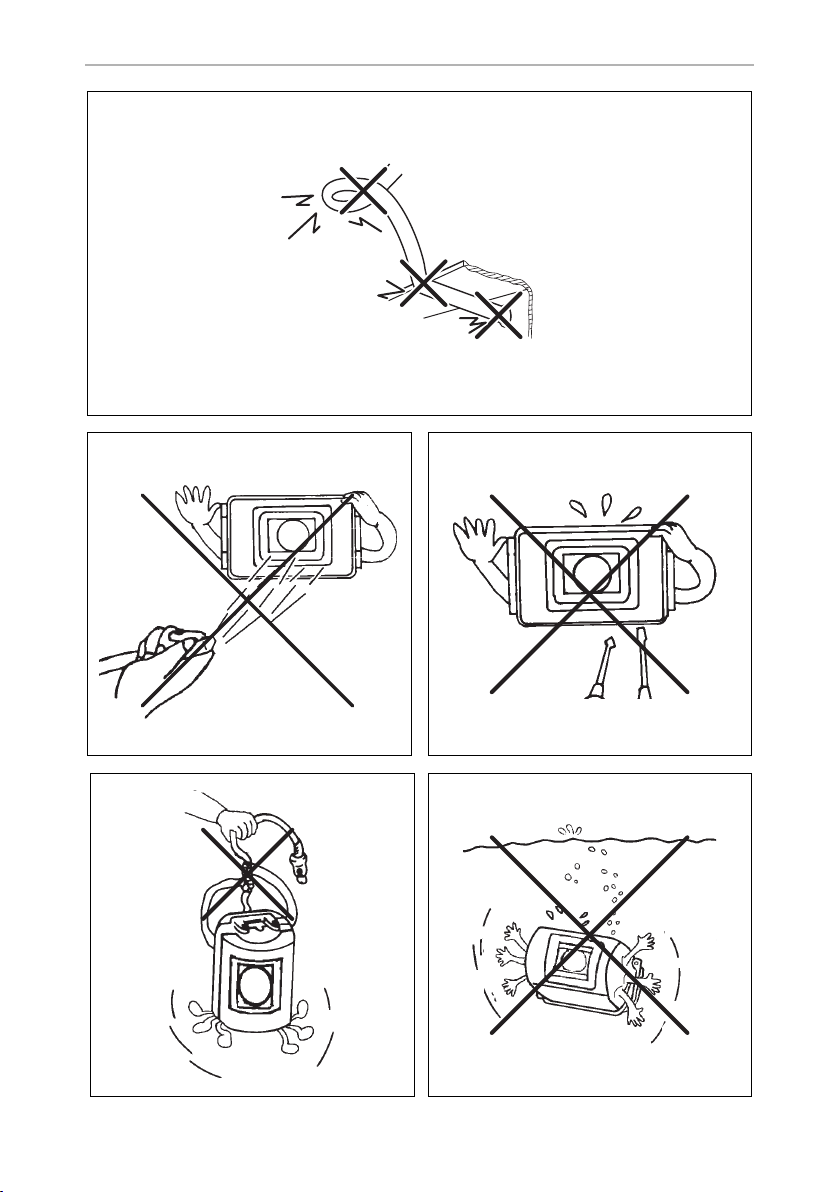
– they are not laid in sharp-edged ducts without protection (fig. 1, page 3).
• Insulate all connections.
• Secure the cables against mechanical wear by using cable binders or insulating
tape, for example on existing cables.
11

EN
Scope of delivery CAM35
The camera is watertight. However, the seals on the camera cannot withstand a highpressure cleaner (fig. 2, page 3). Therefore, you should observe the following
instructions when handling the camera:
• People (including children) whose physical, sensory or mental capacities or
whose lack of experience or knowledge prevent them from using this product
safely should not use it without the supervision or instruction of a responsible
person.
• Do not open the camera, as this impairs the leak tightness and the function of the
camera (fig. 3, page 3).
• Do not pull at the cables, as this impairs the tightness and the function of the camera (fig. 4, page 3).
• The camera is not suitable for use under water (fig. 5, page 3)!
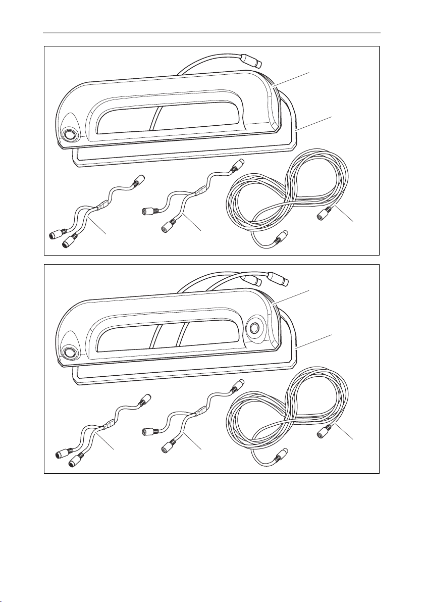
3Scope of delivery
No. in
fig. 6, page 4
1 1 Camera CAM35
2 1 Seal –
3 1 CAM35 Y adapter CAM 9600000552
4 1 CAM35 Y adapter MON 9600000553
5 1 System cable 9600000137
– 1 NAV adapter (only CAM35 REAR NAV
– 2 Fastening bolts 6 x 25 mm
– – Installation and operating manual
Quantity Description Ref. no.
CAM35 REAR
CAM35 REAR NAV
CAM35 TWIN
CAM35 TWIN NAV
or CAM35 TWIN NAV)
9102000134
9102000133
9102000132
9102000131
9600000558
12

EN
CAM35 Intended use
4 Intended use
The double camera CAM 35 is primarily intended for use in the vehicles Fiat Ducato,
Citroën Jumper, Peugeot Boxer starting from model year 2006 with single roof. The
camera console is mounted between the bodywork and the brake light. It can be
used in video systems to observe the space around the vehicle from the driver's seat
when manoeuvring or parking, for example.
WARNING!
!
Danger of personal injury by vehicle.
Reversing video systems are designed merely as an additional aid for
reversing, however this does not relieve you of the duty to take
proper care when reversing.
5 Technical description
The reversing camera and the long-distance camera (only CAM35 TWIN) are
housed in one console for the original brake light. The camera image is transferred
to a monitor via a system cable. The CAM35 is also suitable for connection to the
original Fiat navigation system Uconect, as the cameras provide an NTSC video
signal.
The camera consists of the following elements:
No. in
fig. 8, page 5
1 Reversing camera
2 Long-distance camera (only CAM35 TWIN)
3 6-pin connection cable for long-distance camera (only CAM35 TWIN)
4 6-pin connection cable for reversing camera
Only for CAM35 TWIN
In the CAM35 TWIN, a monitor with two video inputs must be connected that can
be switched between the image of the reversing and the long-distance cameras.
The long-distance camera transmits the image as if you were looking in the rear view
mirror.
Description
13

EN
Fitting the camera CAM35
Only for CAM35 NAV
The cameras CAM35REAR NAV and CAM35 TWIN NAV can be connected to
monitors from other manufacturers. A universal adapter is included (CAM35 NAV
adapter).
6 Fitting the camera
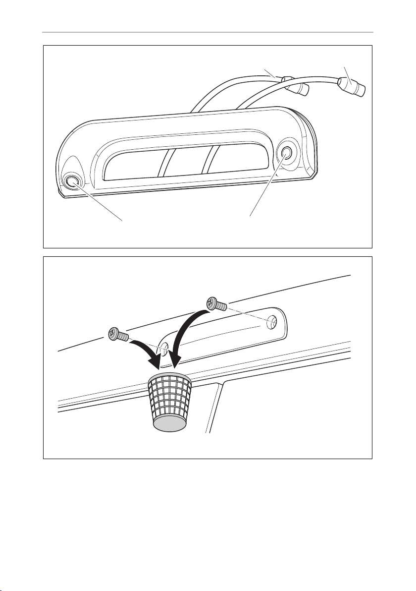
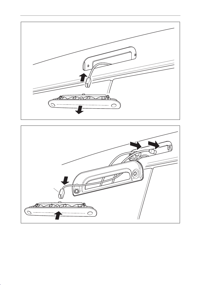
6.1 Dismantling the brake light
➤ Remove the two screws of the brake light (fig. 9, page 5).
➤ Remove the plug of the brake light (fig. 0, page 6).
6.2 Laying cables
NOTICE! Beware of damage.
A
• When drilling holes, check beforehand that there is sufficient space
on the other side for the drill head to come out.
• Cables and connections that are not properly installed will cause
malfunctions or damage to components. Correct installation of
cables and connections ensures lasting and trouble-free operation of
the retrofitted components.
• The cables may not be exposed for long periods to solvents such as
benzene, since solvents can damage the cable.
Therefore, please observe the following instructions:
• As far as possible, use original ducts for laying the cables, or other suitable
options such as panelling edges, ventilation grilles or dummy plugs. If no openings are available, you must drill holes for the cables. Check beforehand that
there is sufficient space on the other side for the drill head to emerge.
• Wherever possible, lay cables inside the vehicle, as they are better protected
there than outside.
If you do need to lay a cable outside the vehicle, ensure that it is well fastened (use
additional cable ties, insulating tape etc.).
14

EN
CAM35 Fitting the camera
• To prevent damage to the cables when laying them, ensure that they are far
enough away from hot or moving vehicle components (exhaust pipes, drive
shafts, light systems, fans, heaters, etc.). Use corrugated piping or other protective materials to protect against mechanical wear.
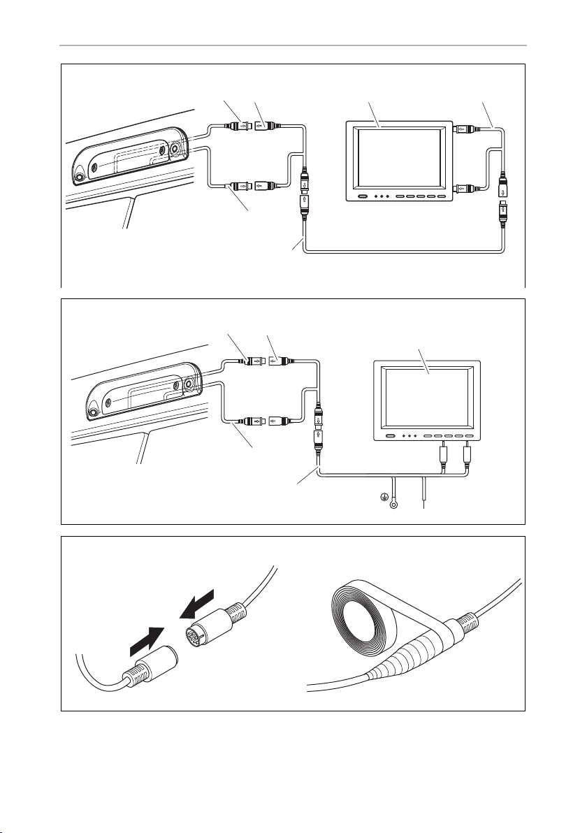
• Screw on the plug connections for the connecting cables to protect them against
water penetration (fig. d, page 7).
• When laying the cables, make sure:
– they are not kinked or twisted
– they do not rub on edges
– they are not laid in sharp-edged ducts without protection.
• Attach the cables securely in the vehicles to prevent tripping hazards. This can be
performed by using cable binders, insulating tape or gluing in place with adhesives.
➤ Lay the system cable.
6.3 Establishing the electrical connection for the camera
NOTE
I
• Lay the camera cable so that, should you need to remove the cam-
era, you can access the plug connection between the camera and
the extension cable easily. This greatly facilitates the disassembly.
• To minimise corrosion in the plug, apply a small amount of grease,
such as pin grease, in one of the plugs.
➤ Guide the connector of the brake light through the console.
➤ Re-attach the plug (fig. a 1, page 6) of the brake light onto the brake light.
➤ Connect the camera as shown in fig. b, page 7 to fig. d, page 7.
15

EN
Fitting the camera CAM35
Legend to fig. b, page 7 and fig. c, page 7:
No. Description
1 6-pin connection cable for reversing camera
2 Y-adapter camera
3 Monitor
4 Y-adapter monitor
5System cable
6 6-pin connection cable for long-distance camera (only CAM35 TWIN)
7 NAV adapter (only CAM35 NAV)
ws white, video signal 1
ge yellow, video signal 2
sw black
rt red
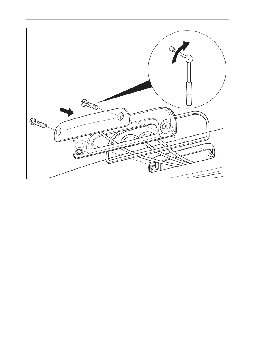
6.4 Fitting the camera
NOTICE!
A
Proceed as follows (fig. e, page 8):
➤ Secure the brake light and the console with two 6 x 25 mm fastening screws.
Make sure to guide the camera cables in the console bottom up to the
notches so that the cables are not pinched.
16

EN
CAM35 Cleaning and caring for the camera
7 Cleaning and caring for the camera
NOTICE! Beware of damage.
A
➤ Clean the camera with a soft, damp cloth from time to time.
Do not use any sharp or hard objects for cleaning since they may damage the device.
8Warranty
The statutory warranty period applies. If the product is defective, please contact the
manufacturer's branch in your country (see the back of the instruction manual for the
addresses) or your retailer.
For repair and guarantee processing, please send the following items:
• Defect components
• A copy of the receipt with purchasing date
• A reason for the claim or description of the fault
9Disposal
➤ Place the packaging material in the appropriate recycling waste bins wherever
possible.
If you wish to finally dispose of the product, ask your local recycling centre
or specialist dealer for details about how to do this in accordance with the
M
applicable disposal regulations.
17

EN
Technical data CAM35
10 Technical data
PerfectView
CAM35 REAR
Ref. no.: 9102000134 9102000133
Image sensor: 1/4" CMOS
Pixels: Approx. 345.000 pixels
Video standard: NTSC
Sensitivity: 1.5 lux
Viewing angle: Approx. 150°/60° diagonal
Operating voltage: 10 Vg to 16 Vg
Consumption: 1 W
Operating temperature: –30 °C to +70 °C
Protection class: IP69k
Vibration resistance: 10g
Dimensions W x H x D
(with bracket):
Weight: Approx. 0.25 kg
80 x 30 x 33 mm
PerfectView
CAM35 REAR NAV
18

EN
CAM35 Technical data
PerfectView
CAM35 TWIN
Ref. no.: 9102000132 9102000131
Image sensor: 1/4" CMOS
Pixels: Approx. 345000 pixels
Video standard: NTSC
Sensitivity: 1.5 lux
Viewing angle: Approx. 150°/60° diagonal
Operating voltage: 10 Vg to 16 Vg
Consumption: 1 W
Operating temperature: –30 °C to +70 °C
Protection class: IP69k
Vibration resistance: 10g
Dimensions W x H x D
(with bracket):
Weight: Approx. 0.25 kg
80 x 30 x 33 mm
PerfectView
CAM35 TWIN NAV
19

DE
Erklärung der Symbole CAM 35
Bitte lesen Sie diese Anleitung vor Einbau und Inbetriebnahme sorgfältig
durch und bewahren Sie sie auf. Geben Sie sie im Falle einer Weitergabe
des Produktes an den Nutzer weiter.
Inhaltsverzeichnis
1 Erklärung der Symbole . . . . . . . . . . . . . . . . . . . . . . . . . . . . . . . . . . . . . . . . . 20
2 Sicherheits- und Einbauhinweise . . . . . . . . . . . . . . . . . . . . . . . . . . . . . . . . . . 21
3 Lieferumfang . . . . . . . . . . . . . . . . . . . . . . . . . . . . . . . . . . . . . . . . . . . . . . . . . 23
4 Bestimmungsgemäßer Gebrauch . . . . . . . . . . . . . . . . . . . . . . . . . . . . . . . . 24
5 Technische Beschreibung . . . . . . . . . . . . . . . . . . . . . . . . . . . . . . . . . . . . . . 24
6 Kamera montieren. . . . . . . . . . . . . . . . . . . . . . . . . . . . . . . . . . . . . . . . . . . . . 25
7 Kamera pflegen und reinigen . . . . . . . . . . . . . . . . . . . . . . . . . . . . . . . . . . . . 28
8 Gewährleistung. . . . . . . . . . . . . . . . . . . . . . . . . . . . . . . . . . . . . . . . . . . . . . . 28
9 Entsorgung . . . . . . . . . . . . . . . . . . . . . . . . . . . . . . . . . . . . . . . . . . . . . . . . . . 28
10 Technische Daten . . . . . . . . . . . . . . . . . . . . . . . . . . . . . . . . . . . . . . . . . . . . . 29
1 Erklärung der Symbole
WARNUNG!
!
A
I
20
Sicherheitshinweis: Nichtbeachtung kann zu Tod oder schwerer
Verletzung führen.
ACHTUNG!
Nichtbeachtung kann zu Materialschäden führen und die Funktion des
Produktes beeinträchtigen.
HINWEIS
Ergänzende Informationen zur Bedienung des Produktes.

DE
CAM35 Sicherheits- und Einbauhinweise
2 Sicherheits- und Einbauhinweise
Beachten Sie die vom Fahrzeughersteller und vom Kfz-Handwerk vorgeschriebenen Sicherheitshinweise und Auflagen!
Der Hersteller übernimmt in folgenden Fällen keine Haftung für Schäden:
• Montage- oder Anschlussfehler
• Beschädigungen am Produkt durch mechanische Einflüsse und Über-
spannungen
• Veränderungen am Produkt ohne ausdrückliche Genehmigung vom Hersteller
• Verwendung für andere als die in der Anleitung beschriebenen Zwecke
Beachten Sie folgende Hinweise:
• Klemmen Sie wegen der Kurzschlussgefahr vor Arbeiten an der Fahrzeugelektrik
immer den Minuspol ab.
Bei Fahrzeugen mit Zusatzbatterie müssen Sie an dieser ebenfalls den Minuspol
abklemmen.
• Unzureichende Leitungsverbindungen können zur Folge haben, dass durch
Kurzschluss
– Kabelbrände entstehen,
– der Airbag ausgelöst wird,
– elektronische Steuerungseinrichtungen beschädigt werden,
– elektrische Funktionen ausfallen (Blinker, Bremslicht, Hupe, Zündung, Licht).
• Verwenden Sie bei Arbeiten an den folgenden Leitungen nur isolierte Kabelschuhe, Stecker und Flachsteckhülsen:
– 30 (Eingang von Batterie Plus direkt),
– 15 (Geschaltetes Plus, hinter Batterie),
– 31 (Rückleitung ab Batterie, Masse),
– 58 (Rückfahrscheinwerfer).
Verwenden Sie keine Lüsterklemmen.
• Verwenden Sie eine Krimpzange zum Verbinden der Kabel.
• Schrauben Sie das Kabel bei Anschlüssen an Leitung 31 (Masse)
– mit Kabelschuh und Zahnscheibe an eine fahrzeugeigene Masseschraube
oder
– mit Kabelschuh und Blechschraube an das Karosserieblech.
Achten Sie auf eine gute Masseübertragung!
21

DE
Sicherheits- und Einbauhinweise CAM35
Beim Abklemmen des Minuspols der Batterie verlieren alle flüchtigen Speicher der
Komfortelektronik ihre gespeicherten Daten.
• Folgende Daten müssen Sie je nach Fahrzeugausstattung neu einstellen:
–Radiocode
–Fahrzeuguhr
– Zeitschaltuhr
– Bordcomputer
– Sitzposition
Hinweise zur Einstellung finden Sie in der jeweiligen Bedienungsanleitung.
Beachten Sie folgende Hinweise bei der Montage:
• Befestigen Sie die im Fahrzeug montierten Teile der Kamera so, dass sie sich
unter keinen Umständen (scharfes Abbremsen, Verkehrsunfall) lösen und zu Ver-
letzungen der Fahrzeuginsassen führen können.
• Befestigen Sie verdeckt unter Verkleidungen anzubringende Teile des Systems
so, dass sie sich nicht lösen oder andere Teile und Leitungen beschädigen und
keine Fahrzeugfunktionen (Lenkung, Pedale usw.) beeinträchtigen können.
• Achten Sie beim Bohren auf ausreichenden Freiraum für den Bohreraustritt, um
Schäden zu vermeiden.
• Entgraten Sie jede Bohrung und behandeln Sie diese mit Rostschutzmittel.
• Beachten Sie immer die Sicherheitshinweise des Fahrzeugherstellers.
Einige Arbeiten (z. B. an Rückhaltesystemen wie AIRBAG usw.) dürfen nur von
geschultem Fachpersonal durchgeführt werden.
Beachten Sie folgende Hinweise bei der Arbeit an elektrischen Teilen:
• Benutzen Sie zum Prüfen der Spannung in elektrischen Leitungen nur eine
Diodenprüflampe oder ein Voltmeter.
Prüflampen mit einem Leuchtkörper nehmen zu hohe Ströme auf, wodurch die
Fahrzeugelektronik beschädigt werden kann.
• Beachten Sie beim Verlegen der elektrischen Anschlüsse, dass diese
– nicht geknickt oder verdreht werden,
– nicht an Kanten scheuern,
– nicht ohne Schutz durch scharfkantige Durchführungen verlegt werden
(Abb. 1, Seite 3).
• Isolieren Sie alle Verbindungen und Anschlüsse.
• Sichern Sie die Kabel gegen mechanische Beanspruchung durch Kabelbinder
oder Isolierband, z. B. an vorhandenen Leitungen.
22

DE
CAM35 Lieferumfang
Die Kamera ist wasserdicht. Die Dichtungen der Kamera halten aber nicht einem
Hochdruckreiniger stand (Abb. 2, Seite 3). Beachten Sie deshalb folgende Hinweise zum Umgang mit der Kamera:
• Personen (einschließlich Kinder), die aufgrund ihrer physischen, sensorischen
oder geistigen Fähigkeiten oder ihrer Unerfahrenheit oder Unkenntnis nicht in
der Lage sind, das Produkt sicher zu benutzen, sollten dieses Produkt nicht ohne
Aufsicht oder Anweisung durch eine verantwortliche Person nutzen.
• Öffnen Sie die Kamera nicht, da dieses ihre Dichtigkeit und die Funktionsfähigkeit beeinträchtigt (Abb. 3, Seite 3).
• Ziehen Sie nicht an den Kabeln, da dieses die Dichtigkeit und die Funktionsfähigkeit der Kamera beeinträchtigt (Abb. 4, Seite 3).
• Die Kamera ist nicht für den Betrieb unter Wasser geeignet (Abb. 5, Seite 3).
3 Lieferumfang
Nr. in
Abb. 6,
Seite 4
11Kamera CAM35
2 1 Dichtung –
3 1 CAM35 Y-Adapter CAM 9600000552
Menge Bezeichnung Artikel-Nr.
CAM35 REAR
CAM35 REAR NAV
CAM35 TWIN
CAM35 TWIN NAV
9102000134
9102000133
9102000132
9102000131
4 1 CAM35 Y-Adapter MON 9600000553
5 1 Systemkabel 9600000137
– 1 NAV-Adapter (nur CAM35 REAR NAV
oder CAM35 TWIN NAV)
– 2 Befestigungsschrauben 6 x 25 mm
– – Montage- und Bedienungsanleitung
9600000558
23

DE
Bestimmungsgemäßer Gebrauch CAM35
4 Bestimmungsgemäßer Gebrauch
Die Doppelkamera CAM35 ist vorrangig für den Einsatz in den Fahrzeugen Fiat
Ducato, Citroën Jumper, Peugeot Boxer ab Modelljahr 2006 mit Einfachdach
gedacht. Die Kamerakonsole wird zwischen Karosserie und Bremsleuchte montiert.
Sie sind einsetzbar in Videosystemen, die zur Beobachtung des Bereiches um das
Fahrzeug vom Fahrersitz aus dienen, z. B. beim Rangieren oder Einparken.
WARNUNG!
!
Gefahr von Personenschäden durch das Fahrzeug.
Rückfahrvideosysteme stellen eine Unterstützung beim Rückwärtsfahren
dar, sie entbinden Sie jedoch nicht von der besonderen Vorsichts-
pflicht beim Rückwärtsfahren.
5 Technische Beschreibung
Die Rückfahrkamera und die Fernsichtkamera (nur CAM35 TWIN) sind in einer
Konsole für die original Bremsleuchte untergebracht. Das Kamerabild wird über ein
Systemkabel übertragen zu einem Monitor. Die CAM35 eignet sich auch zum
Anschluss an das original Fiat Navigationssystem Uconect, da die Kameras ein
NTSC-Videosignal zur Verfügung stellen.
Die Kamera besteht aus u. a. folgenden Elementen:
Nr. in
Abb. 8,
Seite 5
1 Rückfahrkamera
2Fernsichtkamera (nur CAM 35 TWIN)
3 6-poliges Anschlusskabel für Fernsichtkamera (nur CAM35 TWIN)
4 6-poliges Anschlusskabel für Rückfahrkamera
Nur für CAM35 TWIN
Bei der CAM35 TWIN muss ein Monitor mit zwei Videoeingängen angeschlossen
werden, der sich zwischen dem Bild der Rückfahr- und der Fernsichtkamera
umschalten lässt.
Die Fernsichtkamera übermittelt das Bild, als ob Sie in den Rückspiegel blicken.
Bezeichnung
24

DE
CAM35 Kamera montieren
Nur für CAM35 NAV
Die Kameras CAM35REAR NAV und CAM35 TWIN NAV können an Monitore anderer Hersteller angeschlossen werden. Es liegt ein Universaladapter (CAM35 NAVAdapter) bei.
6Kamera montieren
6.1 Bremsleuchte demontieren
➤ Lösen Sie die zwei Schrauben der Bremsleuchte (Abb. 9, Seite 5).
➤ Ziehen Sie den Stecker der Bremsleuchte ab (Abb. 0, Seite 6).
6.2 Kabel verlegen
ACHTUNG! Beschädigungsgefahr!
A
• Wenn Sie Löcher bohren, prüfen Sie vorher, ob ausreichender
Freiraum für den Bohreraustritt vorhanden ist.
• Nicht fachgerechte Kabelverlegungen und Kabelverbindungen
führen immer wieder zu Fehlfunktionen oder Beschädigungen von
Bauteilen. Eine korrekte Kabelverlegung bzw. Kabelverbindung ist
die Grundvoraussetzung für eine dauerhafte und fehlerfreie Funktion
der nachgerüsteten Komponenten.
• Die Kabel dürfen nicht über längere Zeit mit Lösungsmitteln wie
z. B. Benzin in Berührung kommen, da Lösungsmittel die Kabel
beschädigen würden.
Beachten Sie deshalb folgende Hinweise:
• Verwenden Sie für die Durchführung der Anschlusskabel nach Möglichkeit
Originaldurchführungen oder andere Durchführungsmöglichkeiten, z. B. Verkleidungskanten, Lüftungsgitter oder Blindschalter. Wenn keine Durchführungen vorhanden sind, müssen Sie für die jeweiligen Kabel entsprechende Löcher
bohren. Schauen Sie vorher nach, ob ausreichender Freiraum für den Bohreraustritt vorhanden ist.
• Verlegen Sie die Kabel nach Möglichkeit immer im Fahrzeuginneren, denn dort
sind sie besser geschützt als außen am Fahrzeug.
Wenn Sie die Kabel trotzdem außerhalb des Fahrzeuges verlegen, achten Sie auf
eine sichere Befestigung (durch zusätzliche Kabelbinder, Isolierband usw.).
25

DE
Kamera montieren CAM35
• Um Beschädigungen am Kabel zu vermeiden, halten Sie beim Verlegen der
Kabel immer ausreichend Abstand zu heißen und sich bewegenden Fahrzeugteilen (Auspuffrohre, Antriebswellen, Lichtmaschine, Lüfter, Heizung usw.). Verwenden Sie zum mechanischen Schutz Wellrohr oder ähnliche
Schutzmaterialien.
• Verschrauben Sie die Steckverbindungen der Verbindungskabel zum Schutz
gegen das Eindringen von Wasser (Abb. d, Seite 7).
• Beachten Sie beim Verlegen der Kabel, dass diese
– nicht stark geknickt oder verdreht werden,
– nicht an Kanten scheuern,
– nicht ohne Schutz durch scharfkantige Durchführungen verlegt werden.
• Befestigen Sie die Kabel sicher im Fahrzeug, um ein Verfangen (Sturzgefahr) zu
vermeiden. Dieses kann erfolgen durch den Einsatz von Kabelbindern, Isolierband oder durch Ankleben mit Klebstoff.
➤ Verlegen Sie das Systemkabel.
6.3 Kamera elektrisch anschließen
HINWEIS
I
• Verlegen Sie das Kamerakabel so, dass Sie bei einem eventuell
notwendigen Ausbau der Kamera leicht an die Steckerverbindung
zwischen Kamera und Verlängerungskabel kommen.
Die Demontage wird dadurch erheblich vereinfacht.
• Um Korrosion im Stecker zu minimieren, geben Sie etwas Fett, z. B.
Polfett, in einen der Stecker.
➤ Führen Sie den Stecker der Bremsleuchte durch die Konsole.
➤ Stecken Sie den Stecker (Abb. a 1, Seite 6) der Bremsleuchte wieder an die
Bremsleuchte.
➤ Schließen Sie die Kamera an, wie in Abb. b, Seite 7 bis Abb. d, Seite 7
gezeigt.
26

DE
CAM35 Kamera montieren
Legende zu Abb. b, Seite 7 und Abb. c, Seite 7:
Nr. Bezeichnung
1 6-poliges Anschlusskabel für Rückfahrkamera
2Y-Adapter Kamera
3 Monitor
4 Y-Adapter Monitor
5Systemkabel
6 6-poliges Anschlusskabel für Fernsichtkamera (nur CAM35 TWIN)
7 NAV-Adapter (nur CAM35 NAV)
ws weiß, Videosignal 1
ge gelb, Videosignal 2
sw schwarz
rt rot
6.4 Kamera montieren
ACHTUNG!
A
Gehen Sie wie folgt vor (Abb. e, Seite 8):
➤ Befestigen Sie die Bremsleuchte und die Konsole mit den zwei Befestigungs-
schrauben 6 x 25 mm.
Achten Sie darauf, die Kamerakabel in der Konsolenunterseite bis zu
den Ausklinkungen zu führen, damit die Kabel nicht gequetscht
werden.
27

DE
Kamera pflegen und reinigen CAM35
7 Kamera pflegen und reinigen
ACHTUNG! Beschädigungsgefahr!
A
➤ Reinigen Sie die Kamera gelegentlich mit einem weichen, feuchten Tuch.
Keine scharfen oder harten Mittel zur Reinigung verwenden, da dies zu
einer Beschädigung des Geräts führen kann.
8Gewährleistung
Es gilt die gesetzliche Gewährleistungsfrist. Sollte das Produkt defekt sein, wenden
Sie sich bitte an die Niederlassung des Herstellers in Ihrem Land (Adressen siehe
Rückseite der Anleitung) oder an Ihren Fachhändler.
Zur Reparatur- bzw. Gewährleistungsbearbeitung müssen Sie Folgendes einschicken:
• defekte Komponenten,
• eine Kopie der Rechnung mit Kaufdatum,
• einen Reklamationsgrund oder eine Fehlerbeschreibung.
9Entsorgung
➤ Geben Sie das Verpackungsmaterial möglichst in den entsprechenden
Recycling-Müll.
Wenn Sie das Produkt endgültig außer Betrieb nehmen, informieren Sie
sich bitte beim nächsten Recyclingcenter oder bei Ihrem Fachhändler
M
28
über die zutreffenden Entsorgungsvorschriften.

DE
CAM35 Technische Daten
10 Technische Daten
PerfectView
CAM35 REAR
Art.-Nr.: 9102000134 9102000133
Bildsensor: 1/4" CMOS
Bildpunkte: ca. 345.000 Pixel
Videostandard: NTSC
Empfindlichkeit: 1,5 Lux
Blickwinkel: ca. 150°/60° diagonal
Betriebsspannung: 10 Vg bis 16 Vg
Ver brau ch: 1 W
Betriebstemperatur: –30 °C bis +70 °C
Schutzklasse: IP69k
Vibrationsfestigkeit: 10g
Abmessungen B x H x T
(mit Halter):
Gewicht: ca. 0,25 kg
80 x 30 x 33 mm
PerfectView
CAM35 REAR NAV
29

DE
Technische Daten CAM35
PerfectView
CAM35 TWIN
Art.-Nr.: 9102000132 9102000131
Bildsensor: 1/4" CMOS
Bildpunkte: ca. 345.000 Pixel
Videostandard: NTSC
Empfindlichkeit: 1,5 Lux
Blickwinkel: ca. 150°/60° diagonal
Betriebsspannung: 10 Vg bis 16 Vg
Ver brau ch: 1 W
Betriebstemperatur: –30 °C bis +70 °C
Schutzklasse: IP69k
Vibrationsfestigkeit: 10g
Abmessungen B x H x T
(mit Halter):
Gewicht: ca. 0,25 kg
80 x 30 x 33 mm
PerfectView
CAM35 TWIN NAV
30
 Loading...