

Dometic Group CAM200 Installation and Operating Manual [ml]
ENDEFRESPTITNL
DASVNOFIRUPLSKCSHU
POWER & CONTROL
CAMERAS
CAM200
Rear View Video Camera
Installation and Operating Manual . . . . . 12
Rückfahrvideokamera
Montage- und Bedienungsanleitung . . . 20
Caméra vidéo de recul
Instructions de montage
et de service . . . . . . . . . . . . . . . . . . . . . . . 28
Cámara de vídeo de marcha atrás
Instrucciones de montaje y de uso . . . . . 36
Câmara de marcha-atrás
Instruções de montagem e manual de
instruções . . . . . . . . . . . . . . . . . . . . . . . . . 44
Videocamera per la retromarcia
Istruzioni di montaggio e d’uso . . . . . . . .52
Achteruitrijvideocamera
Montagehandleiding en
gebruiksaanwijzing. . . . . . . . . . . . . . . . . . 60
Bakvideokamera
Monterings- og betjeningsvejledning. . . 68
Backningsvideokamera
Monterings- och bruksanvisning. . . . . . . 76
Ryggevideokamera
Monterings- og bruksanvisning . . . . . . . 84
Peruutusvideokamera
Asennus- ja käyttöohje. . . . . . . . . . . . . . . 92
Видеокамера заднего вида
Инструкция по монтажу
и эксплуатации. . . . . . . . . . . . . . . . . . . . 100
Kamera cofania
Instrukcja montażu i obsługi . . . . . . . . . 108
Cúvacia kamera
Návod na montáž a uvedenie
do prevádzky . . . . . . . . . . . . . . . . . . . . . .116
Couvací kamera
Návod k montáži a obsluze . . . . . . . . . . 124
To l a t ó k a m e r a
Szerelési és használati útmutató . . . . . . 132
CAM200
1 2 3
4
9
6
8
5
7
10 11
12
1
2
CAM200
2
3
4
5
3
6
7
1
3
4
2
8
CAM200
4
CAM200
9
5
0
CAM200
6
6-8 mm
1.
2.
a
CAM200
7
CAM200
1.
b
2. 3.
Ø 30
4.
8
CAM200
1.
2.
3.
5.
4.
c
9
CAM200
1.
1.
2.
d
2.
1.
e
f
10
CAM200
2.
3.
4.
1.
g
11

Explanation of symbols CAM200
EN
Please read this instruction manual carefully before installati on and first use, and store
it in a safe place. If you pass on the product to another person, hand over this instruction manual along with it.
Contents
1 Explanation of symbols. . . . . . . . . . . . . . . . . . . . . . . . . . . . . . . . . . . . . . . . . . . . . . . . . . . . . . 12
2 Safety and installation instructions . . . . . . . . . . . . . . . . . . . . . . . . . . . . . . . . . . . . . . . . . . . . . 13
3 Scope of delivery . . . . . . . . . . . . . . . . . . . . . . . . . . . . . . . . . . . . . . . . . . . . . . . . . . . . . . . . . . 15
4 Intended use . . . . . . . . . . . . . . . . . . . . . . . . . . . . . . . . . . . . . . . . . . . . . . . . . . . . . . . . . . . . . . 15
5 Technical description . . . . . . . . . . . . . . . . . . . . . . . . . . . . . . . . . . . . . . . . . . . . . . . . . . . . . . . 15
6 Information on the electrical connections . . . . . . . . . . . . . . . . . . . . . . . . . . . . . . . . . . . . . . . 16
7 Mounting the camera . . . . . . . . . . . . . . . . . . . . . . . . . . . . . . . . . . . . . . . . . . . . . . . . . . . . . . . 17
8 Cleaning and caring for the camera . . . . . . . . . . . . . . . . . . . . . . . . . . . . . . . . . . . . . . . . . . . . 18
9 Guarantee . . . . . . . . . . . . . . . . . . . . . . . . . . . . . . . . . . . . . . . . . . . . . . . . . . . . . . . . . . . . . . . . 18
10 Disposal. . . . . . . . . . . . . . . . . . . . . . . . . . . . . . . . . . . . . . . . . . . . . . . . . . . . . . . . . . . . . . . . . . 18
11 Technical data . . . . . . . . . . . . . . . . . . . . . . . . . . . . . . . . . . . . . . . . . . . . . . . . . . . . . . . . . . . . . 19
1 Explanation of symbols
WARN ING !
!
!
Safety instruction: Indicates a hazardous situation that, if not avoided, could result in
death or serious injury.
CAUTION!
Safety instruction: Indicates a hazardous situation that, if not avoided, could result in
minor or moderate injury.
A
I
12
NOTICE!
Indicates a situation that, if not avoided, can result in property damage.
NOTE
Supplementary information for operating the product.

CAM200 Safety and installation instructions
EN
2 Safety and installation instructions
The manufacturer accepts no liability for damage in the following cases:
•
Faulty assembly or conn ection
•
Damage to the product resulting from mechanical influences and incorrect connection voltage
•
Alterations to the product without express permission from the manufacturer
•
Use for purposes other than those described in the operating manual
Please observe the prescribed safety instructions and stipulations from the vehicle
manufacturer and service workshops.
WARN ING !
Inadequate supply cable connections could result in short circuits, which could have as
!
a consequence that:
•
Cable fires occur
•
The airbag is triggered
•
Electronic control devices are damaged
•
Electric functions fail (indicators, brake light, horn, ignition, lights)
NOTICE!
To prevent the risk of short circuits, always disconnect the negative terminal of the
A
vehicle's electrical system before working on it.
If the vehicle has an additional battery, its negative terminal should also be disconnected.
Please observe the following instructions:
•
When working on the following cables, only use insulated cable lugs, plugs and flat push-on
recepta cles:
– 30 (direct supply from positive battery terminal)
–15 (connected positive terminal, behind the battery)
– 31 (return line from the battery, earth)
– L (indicator lights left)
– R (indicator lights right)
Do not use terminal strips.
•
Use a crimping tool to connect the cables.
•
When connecting to cable 31 (earth), screw the cable
– to the vehicle's earth bolt with a cable lug and a gear disc or
– to the sheet-metal bodywork with a cable lug and a self-tapping screw.
Ensure that there is a good earth connection.
13

Safety and installation instructions CAM200
EN
If you disconnect the negative terminal of the battery, all data stored in the volatile memories will
be lost.
•
The following data must be set again, depending on the vehicle equipment options:
–Radio code
– Vehicle clock
–Timer
– On-board computer
– Seat position
You can find instructions for making these settings in the appropriate operating instructions.
Observe the following installation instructions:
CAUTION!
•
!
A
Observe the following instructions when working with electrical parts:
A
Secure the parts installed in the vehicle in such a way that they cannot become loose
under any circumstances (sudden braking, accidents) and cause injuries to the
occupants of the vehicle.
•
Secure any parts of the system covered by the bodywork in such a manner that they
cannot be come loose or damage other parts and cables or impair vehicle functions
(steering, pedals, etc).
•
Always follow the safety instructions of the v ehicle manufacturer.
Some work (e.g. on retention systems such as the AIRBAG etc.) may only be
performed by qualified specialists.
NOTICE!
•
To prevent damage when drilling, make sure there is sufficient space on the other
side for the drill head to come out.
•
Deburr all drill holes and treat them with a rust-protection agent.
NOTICE!
•
When testing the voltage in electrical cables, only use a diode test lamp or a
voltmeter.
Test lamps with an illuminant take up voltages which are too high and which can
damage the vehicle's electronic system.
•
When making electrical connections, ensure that:
– they are not kinked or twisted
– they do not rub on edges
– they are not laid in sharp edged ducts without protection.
•
Insulate all connections.
•
Secure the cables against mechanical wear with cable binders or insulating tape,
for example to existing cables.
14

CAM200 Scope of delivery
EN
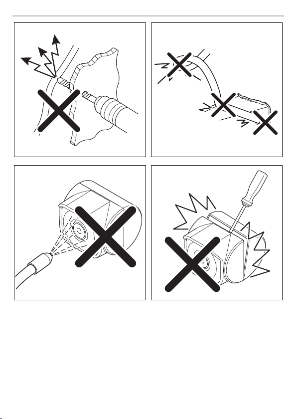
The camera is watertight. However, the sealings on the camera cannot withstand a high-pres-
sure cleaner (fig. 4, page 3).
Observe also the following instructions:
•
Do not open the camera, as this impairs the sealing and the function of the camera (fig. 5,
page 3).
•
Do not pull at the cables, as this impairs the sealing and the function of the camera (fig. 6,
page 4).
•
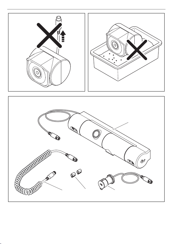
The camera is not suitable for submerged operation (fig. 7, page 4).
3Scope of delivery
No. in
fig. 8,
page 4
Quantity Description Ref. no.
1 1 Camera CAM 200 9600026080
2 1 Connector grommet 9600027073
3 2 Cable clip
4 1 Spiral cable 9600026478
– 1 Installation and Operating Manual
4Intended use
The camera CAM 200 is a rear view video camera for use on bike racks.
The camera can be used to observe the space around the vehicle from the driver's seat when
manoeuvring or parking, for example.
WARN ING !
!
Risk of injury!
Since rear view systems are designed merely as an additional aid for reversing, it does
not relieve you of the duty to take proper care when reversing.
5 Technical description
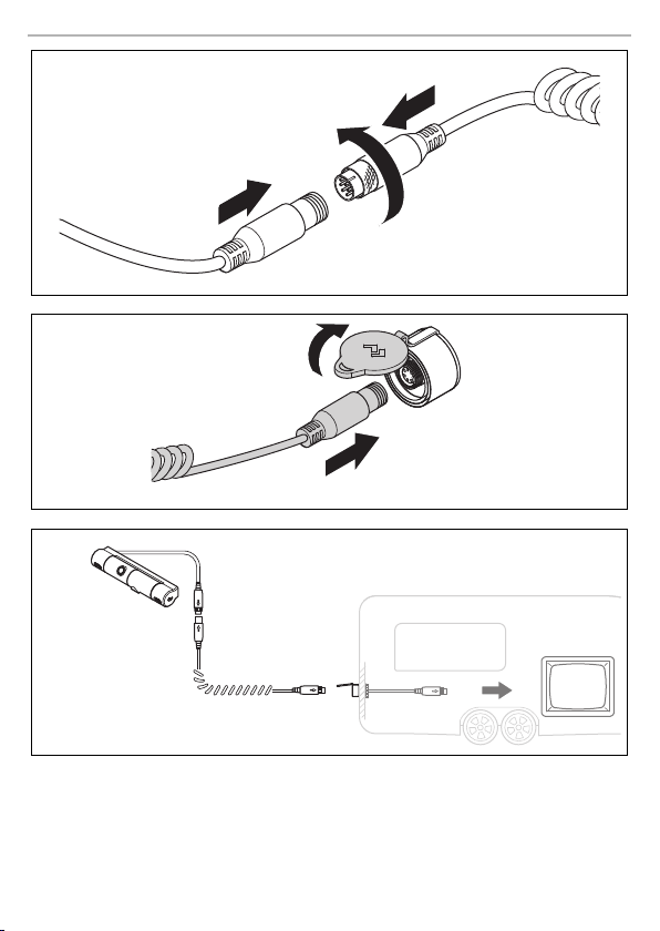
The camera, which is encased in plastic housing, transmits the image to a monitor via a cable.
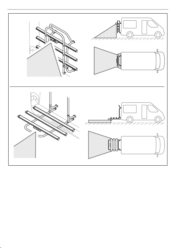
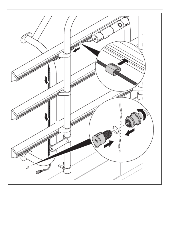
The camera is mounted under the profile of the bike rack and provides a free view with a loaded
bike rack.
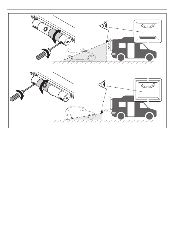
Two automatically operating camera modules provide the image with the bike rack folded up or
down (fig. 9, page 5).
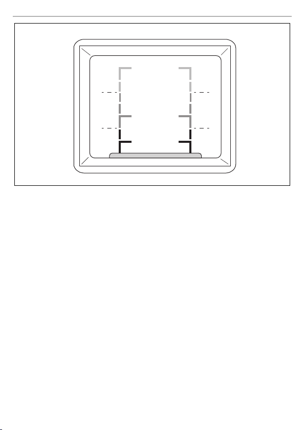
Three distance lines (green, yellow, and red) are displayed (fig. 0, page 6).
15

Information on the electrical connections CAM200
EN
6 Information on the electrical connections
6.1 Laying cables
NOTICE! Risk of damage!
•
A
Please observe the following instructions:
•
As far as possible, use original openings or alternative openings for the connecting cable duct,
e.g. the paneling edges, ventilation grilles or blank panels. If no openings are available, you
must drill holes for the cables. Check beforehand that there is sufficient room for the drill head
to come out on the other side.
•
Wherever possible lay cables inside the vehicle, as they are better protected inside than outside
the vehicle.
If you do need to lay a cable outside the vehicle, ensure that it is we ll secured (use additional
cable ties, insulating tape, etc.).
•
To prevent damage to the cables, when laying them ensure that there is sufficient distance to
hot or moving vehicle components (exhaust pipes, drive shaf ts, light systems, fans, heater etc.).
Use corrugated piping or other protective materials to protect against mechanical wear.
•
Screw on the plug connection of the connecting cables to protect against water penetration
(fig. d, page 10).
•
When laying electric connections, ensure that
•
Attach the cables securely in the vehicles to prevent tripping hazards. Use cable binders, insulating tape or glue the cables in place.
•
Protect every through-hole made in the bodywork against water penetration, e.g. by using a
cable with a sealant and by spraying the cable and the cable sleeve with sealant.
To prevent damage, when drilling ensure that there is sufficient space on the other
side for the drill head to come out.
•
Cables and connections which are not properly installed will cause malfunctions or
damage to components. Correct installation of cables and connections is the basic
prerequisite for lasting and trouble-free operation of the retrofitted components.
•
The cables may not be exposed for long periods to solvents such as ben zine, as the
solvents can damage the cable.
– They are not kinked or twisted
– They do not rub on edges
– They are not laid in sharp edged ducts without protection (fig. 3, page 3)
I
16
NOTE
Do not start sealing the through-holes until all installation work has been finished for the
camera, and the required cable lengths have been established.

CAM200 Mounting the camera
EN
7 Mounting the camera
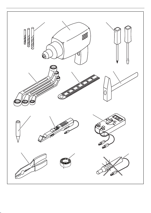
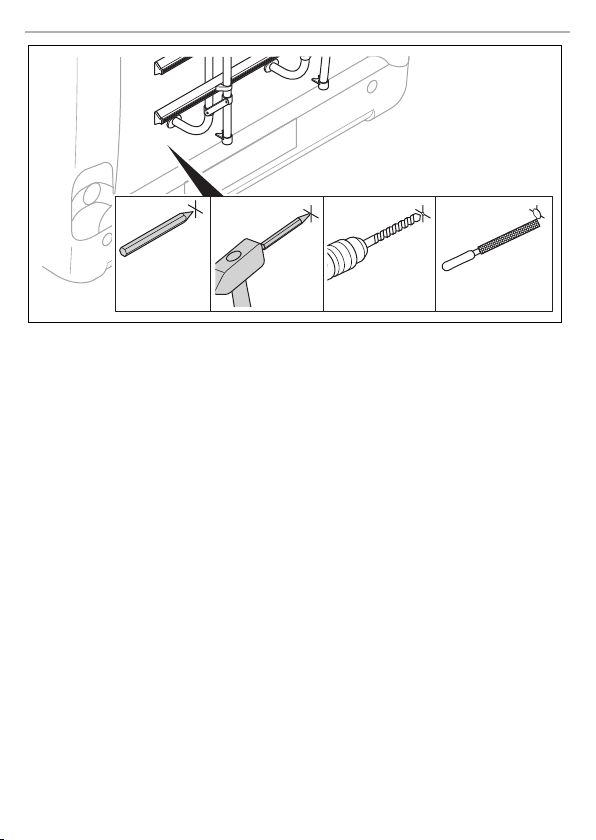
7.1 Too ls re qu ir ed
For installation and assembly you will require the following tools:
•
Drill bit set (fig. 1 1, page 2)
•
Drill (fig. 1 2, page 2)
•
Screwdriver (fig. 1 3, page 2)
•
Set of ring or open-ended spanners (fig. 1 4, page 2)
•
Measuring ruler (fig. 1 5, page 2)
•
Hammer (fig. 1 6, page 2)
•
Centre punch (fig. 1 7, page 2)
To make and test the electrical connection, the following tools are required:
•
Diode test lamp (fig. 1 8, page 2) or voltmeter (fig. 1 9, page 2)
•
Crimping tool (fig. 1 10, page 2)
•
Insulating tape (fig. 1 11, page 2)
•
Cable bushing sleeves, if necessary
To fasten the cables you may require additional cable binders.
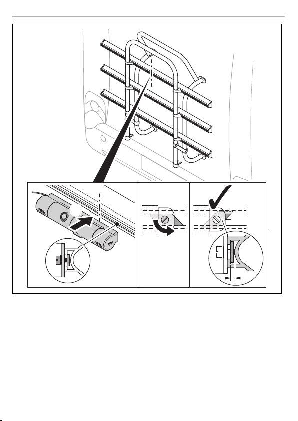
7.2 Mounting and connecting the camera
Proceed as shown (fig. a, page 7 to fig. f, page 10).
NOTICE! Risk of damage!
A
I
Ensure that there is sufficient space on the other side for the drill head to come out
NOTE
To min imise corr osion in th e plug, app ly a small a mount of gr ease – such as pin grea se
– inside the plug.
Aligning the camera
➤ Use the monitor image to align the camera (fig. g, page 11).
➤ Use the monitor image to check the function of the camera.
17

Cleaning and caring for the camera CAM200
EN
8 Cleaning and caring for the camera
NOTICE! Risk of damage!
A
➤ Clean the camera with a soft, damp cloth from time to time.
Do not use sharp or hard objects to clean the device as these may dam age the device.
9Guarantee
The statutory warranty period applies. If the product is defective, please contact the
manufacturer's branch in your country (see back page) or your retailer.
For repair and warranty processing, please send the following items:
•
Defect components
•
A copy of the receipt with purchasing date
•
A reason for the claim or description of the fault
10 Disposal
➤ Place the packaging material in the appropriate recycling waste bins wherever possible.
If you wish to finally dispose of the product, ask your local recycling centre or specialist
dealer for details about how to do this in accordance with the applicable disposal
M
regulations.
18

CAM200 Technical data
EN
24
11 Technical data
PerfectView CAM200
Ref. no: 9600000049
Image sensor: 1/4" CMOS
Pixels: approx. 307000 pixels
Video standard: NTSC
Light sensitivity: 0,1 Lux
Operating voltage: 10 – 16 Vg
Power consumption: 1 W
Protection class: IP69
Operating temperature: –30 °C to 70 °C
Dimensions W x H x D: 165 x 35 x 42 mm
Weight: 250 g
Approval
The device has the E24 approval.
19

Erklärung der Symbole CAM200
DE
Bitte lesen Sie diese Anleitung vor Einbau und Inbetriebnahme sorgfältig durch und
bewahren Sie sie auf. Geben Sie sie im Falle einer Weitergabe des Produktes an den
Nutzer weiter.
Inhaltsverzeichnis
1 Erklärung der Symbole . . . . . . . . . . . . . . . . . . . . . . . . . . . . . . . . . . . . . . . . . . . . . . . . . . . . . .20
2 Sicherheits- und Einbauhinweise. . . . . . . . . . . . . . . . . . . . . . . . . . . . . . . . . . . . . . . . . . . . . . 21
3 Lieferumfang . . . . . . . . . . . . . . . . . . . . . . . . . . . . . . . . . . . . . . . . . . . . . . . . . . . . . . . . . . . . . .23
4 Bestimmungsgemäßer Gebrauch . . . . . . . . . . . . . . . . . . . . . . . . . . . . . . . . . . . . . . . . . . . . .23
5 Technische Beschreibung . . . . . . . . . . . . . . . . . . . . . . . . . . . . . . . . . . . . . . . . . . . . . . . . . . .24
6 Hinweise zum elektrischen Anschluss . . . . . . . . . . . . . . . . . . . . . . . . . . . . . . . . . . . . . . . . . .24
7 Kamera montieren . . . . . . . . . . . . . . . . . . . . . . . . . . . . . . . . . . . . . . . . . . . . . . . . . . . . . . . . . 25
8 Kamera pflegen und reinigen. . . . . . . . . . . . . . . . . . . . . . . . . . . . . . . . . . . . . . . . . . . . . . . . .26
9 Gewährleistung . . . . . . . . . . . . . . . . . . . . . . . . . . . . . . . . . . . . . . . . . . . . . . . . . . . . . . . . . . .26
10 Entsorgung . . . . . . . . . . . . . . . . . . . . . . . . . . . . . . . . . . . . . . . . . . . . . . . . . . . . . . . . . . . . . . .26
11 Technische Daten . . . . . . . . . . . . . . . . . . . . . . . . . . . . . . . . . . . . . . . . . . . . . . . . . . . . . . . . . .27
1 Erklärung der Symbole
WARN UNG !
!
!
Sicherheitshinweis auf eine Gefahrensituation, die zum Tod oder zu schwerer
Verletzung führen kann, wenn sie nicht vermieden wird.
VORSIC HT!
Sicherheitshinweis auf eine Gefahrensituation, die zu einer leichten oder mittel-
schweren Verletzung führen kann, wenn sie nicht vermieden wird.
A
I
20
ACHTUNG!
Hinweis auf eine Situation, die zu Sachschäden führen kann, wenn sie nicht vermieden
wird.
HINWEIS
Ergänzende Informationen zur Bedienung des Produktes.

CAM200 Sicherheits- und Einbauhinweise
DE
2 Sicherheits- und Einbauhinweise
Der Hersteller übernimmt in folgenden Fällen keine Haftung für Schäden:
•
Montage- oder Anschlussfehler
•
Beschädigungen am Produkt durch mechanische Einflüsse und falsche Anschlussspannung
•
Veränderungen am Produkt ohne ausdrückliche Genehmigung vom Hersteller
•
Verwendung für andere als die in der Anleitung beschriebenen Zwecke
Beachten Sie die vom Fahrzeughersteller und vom Kfz-Handwerk vorgeschriebenen
Sicherheitshinweise und Auflagen!
WARN UNG !
Unzureichende Leitungsverbindungen können zur Folge haben, dass durch Kurzschluss
!
•
Kabelbrände entstehen,
•
der Airbag ausgelöst wird,
•
elektronische Steuerungseinrichtungen beschädigt werden,
•
elektrische Funktionen ausfallen (Blinker, Bremslicht, Hupe, Zündung, Licht).
ACHTUNG!
Klemmen Sie wegen der Kurzschlussgefahr vor Arbeiten an der Fahr zeugelektrik immer
A
den Minuspol ab.
Bei Fahrzeugen mit Zusatzbatterie müssen Sie an dieser ebenfalls den Minuspol
abklemmen.
Beachten Sie deshalb folgende Hinweise:
•
Verwenden Sie bei Arbeiten an den folgenden Leitungen nur isolierte Kabelschuhe, Stecker
und Flachsteckhülsen:
– 30 (Eingang von Batterie Plus direkt)
– 15 (Geschaltetes Plus, hinter Batterie)
– 31 (Rückleitung ab Batterie, Masse)
– L (Blinkerleuchten links)
– R (Blinkerleuchten rechts)
Verwen den S ie kein e Lüsterklemmen.
•
Verwenden Sie eine Krimpzange zum Verbinden der Kabel.
•
Schrauben Sie das Kabel bei Anschlüssen an Leitung 31 (Masse)
– mit Kabelschuh und Zahnscheibe an eine fahrzeugeigene Masseschraube oder
– mit Kabelschuh und Blechschraube an das Karosserieblech.
Achten Sie auf eine gute Masseübertragung!
21

Sicherheits- und Einbauhinweise CAM200
DE
Beim Abklemmen des Minuspols der Batterie verlieren alle flüchtigen Speicher der Komfortelektronik ihre gespeicherten Daten.
•
Folgende Daten müssen Sie je nach Fahrzeugausstattung neu einstellen:
–Radiocode
–Fahrzeuguhr
– Zeitschaltuhr
– Bordcomputer
– Sitzposition
Hinweise zur Einstellung finden Sie in der jeweiligen Bedienungsanleitung.
Beachten Sie folgende Hinweise bei der Montag e:
VORSIC HT!
•
!
A
Beachten Sie folgende Hinweise bei der Arbeit an elektrischen Teilen:
A
Befestigen Sie die im Fahrzeug montierten Teile so, dass sie sich unter keinen
Umständen (scharfes Abbremsen, Verkehrsunfall) lösen und zu Verletzungen der
Fahrzeuginsassen führen können.
•
Befestigen Sie verdeckt unter Verkleidungen anzubringende Teile des Systems so,
dass sie sich nicht lösen oder andere Teile und Leitungen beschädigen und keine
Fahrzeugfunktionen (Lenkung, Pedale usw.) beeinträchtigen können.
•
Beachten Sie immer die Sicherheitshinweise des Fahrzeugherstellers.
Einige Arbeiten (z. B. an Rückhaltesystemen wie Airbag usw.) dürfen nur von
geschultem Fachpersonal durchgeführt werden.
ACHTUNG!
•
Achten Sie beim Bohren auf ausreichenden Freiraum für den Bohreraustritt, um
Schäden zu vermeiden.
•
Entgraten Sie jede Bohrung und behandeln Sie diese mit Rostschutzmittel.
ACHTUNG!
•
Benutzen Sie zum Prüfen der Spannung in elektrischen Leitungen nur eine Diodenprüflampe oder ein Voltmeter.
Prüflampen mit einem Leuchtkörper nehmen zu hohe Ströme auf, wodurch die
Fahrzeugelektronik beschädigt werden kann.
•
Beachten Sie beim Verlegen der elektrischen Anschlüsse, dass diese
– nicht geknickt oder verdreht werden,
– nicht an Kanten scheuern,
– nicht ohne Schutz durch scharfkantige Durchführungen verlegt werden.
•
Isolieren Sie alle Verbindungen und Anschlüsse.
•
Sichern Sie die Kabel gegen mechanische Beanspruchung durch Kabelbinder oder
Isolierband, z. B. an vorhandenen Leitungen.
22

CAM200 Lieferumfang
DE
Die Kamera ist wasserdicht. Die Dichtungen der Kamera halten aber nicht einem Hochdruck-
reiniger stand (Abb. 4, Seite 3).
Beachten Sie auch folgende Hinweise:
•
Öffnen Sie die Kamera nicht, da dieses ihre Di chtigkeit und die Funktionsfähigkeit beeinträch-
tigt (Abb. 5, Seite 3).
•
Ziehen Sie nicht an den Kabeln, da dieses die Dichtigkeit und die Funktionsfähigkeit der
Kamera beeinträchtigt (Abb. 6, Seite 4).
•
Die Kamera ist nicht für den Betrieb unter Wasser geeignet (Abb. 7, Seite 4).
3Lieferumfang
Nr. in
Abb. 8,
Seite 4
1 1 Kamera CAM200 9600026080
2 1 Kabeld urchführun g 9600027073
32Kabelclip
4 1 Spiralkabel 9600026478
–1Montage- und Bedienungsanleitung
Menge Bezeichnung Artikel-Nr.
4 Bestimmungsgemäßer Gebrauch
Die Kamera CAM 200 ist eine Rückfahrkamera für den Einsatz an Fahrradträgern.
Die Kamera dient zur Beobachtung des Bereiches hinter dem Fahrzeug vom Fahrersitz aus, z. B.
beim Rangieren oder Einparken.
WARN UNG !
!
Gefahr von Personenschäden durch das Fahrzeug.
Rückfahrvideosysteme stellen eine Unterstützung beim Rückwärtsfahren dar,
sie entbinden Sie jedoch nicht von der besonderen Vorsichtspflicht beim
Rückwärtsfahren.
23

Technische Beschreibung CAM200
DE
5 Technische Beschreibung
Die Kamera ist in einem Kunststo ffgehäuse untergebracht und überträgt das Bild übe r einen Kabel
zu einem Monitor.
Die Kamera wird unter dem Fahrradträgerprofil montiert und ermöglicht freie Sicht bei einem
beladenen Fahrradträger.
Zwei automatisch schaltende Kameramodule liefern die Darstellung bei hochgeklappten und
abgeklappten Fahrradträger (Abb. 9, Seite 5).
Drei Abstandslinien (grün, gelb und rot) werden eingeblendet (Abb. 0, Seite 6).
6 Hinweise zum elektrischen Anschluss
6.1 Kabel verlegen
ACHTUNG! Beschädigungsgefahr!
•
A
Beachten Sie deshalb folgende Hinweise:
•
Verwenden Sie für die Durchführung der Anschlusskabel nach Möglichkeit Originaldurch-
führungen oder andere Durchführungsmöglichkeiten, z. B. Verkleidungskanten, Lüftungsgitter
oder Blindschalter. Wenn keine Durchführungen vorhanden sind, müssen Sie für die jeweiligen
Kabel entsprechende Löcher bohren. Schauen Sie vo rher nach, ob ausreichender Freiraum für
den Bohreraustritt vorhanden ist.
•
Verlegen Sie die Kabel nach Möglichkeit immer im Fah rzeuginneren, denn dort sind sie besser
geschützt als außen am Fahrzeug.
Wenn Sie die Kabel trotzdem außerhalb des Fahrzeuges verlegen, achten Sie auf eine sichere
Befestigung (durch zusätzliche Kabelbinder, Isolierband usw.).
•
Um Beschädigungen am Kabel zu vermeiden, halten Sie beim Verlegen der Kabel immer
ausreichend Abstand zu heißen und sich bewegenden Fahrzeugteilen (Auspuffrohre,
Antriebswellen, Lichtmaschine, Lüfter, Heizung usw.). Verwenden Sie zum mechanischen
Schutz Wellrohr oder ähnliche Schutzmaterialien.
•
Verschrauben Sie die Steckverbindungen der Verbindungskabel zum Schutz gegen das
Eindringen von Wasser (Abb. d, Seite 10).
Wenn Sie Löcher bohren, prüfen Sie vorher, ob ausreichender Freiraum für den
Bohreraustritt vorhanden ist (Abb. 2, Seite 3).
•
Nicht fachgerechte Kabelverlegungen und Kabelverbindungen führen immer
wieder zu Fehlfunktionen oder Beschädigung en von Bauteilen. Eine korrekte
Kabelverlegung bzw. Kabelverbindung ist die Grundvoraussetzung für eine
dauerhafte und fehlerfreie Funktion der nachgerüsteten Komponenten.
•
Die Kabel dürfen nicht über längere Zeit mit Lösungsmitteln wie z. B. Benzin in
Berührung kommen, da Lösungsmittel die Kabel beschädigen würden.
24

CAM200 Kamera montieren
DE
•
Beachten Sie beim Verlegen der Kabel, dass diese
– nicht stark geknickt oder verdreht werden,
–nicht an Kanten scheuern,
– nicht ohne Schutz durch scharfkantige Durchführungen verlegt werden (Abb. 3, Seite 3).
•
Befestigen Sie die Kabel sicher im Fahrzeug, um ein Verfangen (Sturzgefahr) zu vermeiden.
Dieses kann erfolgen durch den Einsatz von Kabelbindern, Isolierband oder durch Ankleben
mit Klebstoff.
•
Schützen Sie jeden Durchbruch an der Auße nhaut durch geeignete Maßnahmen gegen
Wassereinbruch, z. B. durch Einsetzen des Kabels mit Dichtungsmasse und durch Abspritzen
des Kabels und der Durchführungstülle mit Dichtungsmasse.
HINWEIS
I
Beginnen Sie mit dem Abdichten der Durchbrüche erst, nachdem alle Einstella rbeiten
an der Kamera abgeschlossen sind und die benötigten Längen der Anschlusskabel
festliegen.
7 Kamera montieren
7.1 Be nö ti gt es Werk zeu g
Für Einbau und Montage benötigen Sie folgende Werkzeuge:
•
Satz Bohrer (Abb. 1 1, Seite 2)
•
Bohrmaschine (Abb. 1 2, Seite 2)
•
Schraubendreher (Abb. 1 3, Seite 2)
•
Satz Ring- oder Maulschlüssel (Abb. 1 4, Seite 2)
•
Maßstab (Abb. 1 5, Seite 2)
•
Hammer (Abb. 1 6, Seite 2)
•
Körner (Abb. 1 7, Seite 2)
Für den elektrischen Anschluss und seine Überprüfung benötigen Sie folgende Hilfsmittel:
•
Diodenprüflampe (Abb. 1 8, Seite 2) oder Voltmeter (Abb. 1 9, Seite 2)
•
Krimpzange (Abb. 1 10, Seite 2)
•
Isolierband (Abb. 1 11, Seite 2)
•
Ggf. Kabeldurchführungstüllen
Zur Befestigung der Kabel benötigen Sie ggf. noch weitere Kabelbinder.
25

Kamera pflegen und reinigen CAM200
DE
7.2 Kamera montieren und anschließen
Gehen Sie vor wie dargestellt (Abb. a, Seite 7 bis Abb. f, Seite 10).
ACHTUNG! Beschädigungsgefahr!
A
I
Kamera ausrichten
➤ Richten Sie die Kamera anhand des Monitorbildes aus (Abb. g, Seite 11):
➤ Prüfen Sie die Funktion der Kamera anhand des Monitorbildes.
Kontrollieren Sie vorher, ob ausreichender Freiraum für den Bohreraustritt vorhanden
ist (Abb. 2, Seite 3).
HINWEIS
Um Korrosion im Stecker zu minimieren, geben Sie etwas Fett, z. B. Polfett, in einen
der Stecker.
8 Kamera pflegen und reinigen
ACHTUNG! Beschädigungsgefahr!
A
➤ Reinigen Sie die Kamera gelegentlich mit einem weichen, feuchten Tuch.
Keine scharfen oder harten Mittel zur Reinigung verwenden, da dies zu einer
Beschädigung des Geräts führen kann.
9Gewährleistung
Es gilt die gesetzliche Gewährleistungsfrist. Sollte das Produkt defekt sein, wenden Sie sich bitte
an die Niederlassung des Herstellers in Ihrem Land (siehe Rückseite) oder an Ihren Fachhändler.
Zur Reparatur- bzw. Gewährleistungsbearbeitung müssen Sie Folgendes einschicken:
•
defekte Komponenten,
•
eine Kopie der Rechnung mit Kaufdatum,
•
einen Reklamationsgrund oder eine Fehlerbeschreibung.
10 Entsorgung
➤ Geben Sie das Verpackungsmaterial möglichst in den entsprechenden Recycling-Müll.
Wenn Sie das Produkt endgültig außer Betrieb nehmen, informieren Sie sich bitte beim
nächsten Recyclingcenter oder bei Ihrem Fachhändler über die zutreffenden
M
Entsorgungsvorschriften.
26

CAM200 Technische Daten
DE
24
11 Technische Daten
Perfe ctView CA M200
Art.-Nr.: 9600026080
Bildsensor: 1/4" CMOS
Bildpunkte: ca. 307000 Pixel
Videostandard: NTSC
Empfindlichkeit: 0,1 Lux
Betriebsspannung: 10 – 16 Vg
Ver brau ch: 1 W
Schutzklasse: IP69K
Betriebstemperatur: –30 °C bis 70 °C
Abmessungen B x H x T 165 x 35 x 42 mm
Gewicht: 250 g
Zulassungen
Das Gerät hat die E24-Zulassung.
27

Signification des symboles CAM200
FR
Veuillez lire attentivement cette notice avant le montage et la mise en service. Veuillez
ensuite la conserver. En cas de passer le produit, veuillez le transmettre au nouvel
acquéreur.
Sommaire
1 Signification des symboles . . . . . . . . . . . . . . . . . . . . . . . . . . . . . . . . . . . . . . . . . . . . . . . . . . .28
2 Consignes de sécurité et instructions de montage. . . . . . . . . . . . . . . . . . . . . . . . . . . . . . . .29
3 Contenu de la livraison . . . . . . . . . . . . . . . . . . . . . . . . . . . . . . . . . . . . . . . . . . . . . . . . . . . . . . 31
4 Usage conforme . . . . . . . . . . . . . . . . . . . . . . . . . . . . . . . . . . . . . . . . . . . . . . . . . . . . . . . . . . . 31
5 Description technique . . . . . . . . . . . . . . . . . . . . . . . . . . . . . . . . . . . . . . . . . . . . . . . . . . . . . . 31
6 Remarques concernant le raccordement électrique . . . . . . . . . . . . . . . . . . . . . . . . . . . . . . . 32
7 Montage de la caméra . . . . . . . . . . . . . . . . . . . . . . . . . . . . . . . . . . . . . . . . . . . . . . . . . . . . . .33
8 Entretien et nettoyage de la caméra . . . . . . . . . . . . . . . . . . . . . . . . . . . . . . . . . . . . . . . . . . . 34
9 Garantie. . . . . . . . . . . . . . . . . . . . . . . . . . . . . . . . . . . . . . . . . . . . . . . . . . . . . . . . . . . . . . . . . . 34
10 Retraitement . . . . . . . . . . . . . . . . . . . . . . . . . . . . . . . . . . . . . . . . . . . . . . . . . . . . . . . . . . . . . . 34
11 Caractéristiques techniques. . . . . . . . . . . . . . . . . . . . . . . . . . . . . . . . . . . . . . . . . . . . . . . . . .35
1Signification des symboles
AVERTISSEMENT !
!
!
Consigne de sécurité signalant une situation dangereuse qui peut entraîner la mort
ou de graves blessures si elle n’est pas évitée.
ATTENTION !
Consigne de sécurité signalant une situation dangereuse qui peut entraîner des
blessures de gravité moyenne ou légère si elle n’est pas évitée.
A
I
28
AVIS !
Remarque signalant une situation qui peut entraîner des dommages matériels si elle
n’est pas évitée.
REMARQUE
Informations complémentaires sur l'utilisation du produit.

CAM200 Consignes de sécurité et instructions de montage
FR
2 Consignes de sécurité et instructions de montage
Le fabricant décline toute responsabilité pour des dommages dans les cas suivants :
•
des défauts de montage ou de raccordement
•
des sollicitations mécaniques et une tension de raccordement incorrecte ayant endommagé le
matériel
•
des modifications apportées au produit sans autorisation explicite de la part du fabricant
•
une utilisation différente de celle décrite dans la notice
Respectez les consignes de sécurité et autres prescriptions imposées par le fabricant
du véhicule et par les professionnels de l'automobile !
AVERTISSEMENT !
Tout branchement électrique inadéquat peut entraîner un court-circuit causant
!
•
la combustion de câbles,
•
le déclenchement de l'airbag,
•
l’endommagement des dispositifs électroniques de commande,
•
la défaillance des fonctions électriques (c lignotants, feux-stop, klaxon, allumage,
éclairage).
AVIS !
Débranchez toujours la borne négative avant de procéder à des travaux sur les éléments
A
électriques du véhicule afin d’éviter tout risque de court-circuit.
Sur les véhicules équipés d’une batterie supplémentaire, vous devez également
débrancher le pôle négatif de cette dernière.
Veuillez donc respecter les consignes suivantes :
•
Pour tous les travaux sur les lignes électriques suivantes, n’utilisez que des cosses de câble,
fiches et alvéoles pour contacts plats isolés :
– 30 (entrée directe pôle positif de la batterie)
–15 (pôle positif connecté, derrière la batterie)
– 31 (ligne de retour à partir de la batterie, masse)
– L (clignotants gauches)
– R (clignotants droits)
N’utilisez pas de dominos.
•
Utilisez une pince à sertir pour relier les câbles.
•
Pour les raccordements à la ligne électrique 31 (masse), vissez le câble
– à une vis de masse du véhicule, avec une cosse et une rondelle crantée, ou bien
– à la carrosse rie, avec une cosse et une vis à tôle.
Veillez à une bonne transmission de la masse !
29

Consignes de sécurité et instructions de montage CAM200
FR
Lorsque vous débranchez le pôle négatif de la batterie, les mémoires volatiles de l’électronique de
confort perdent toutes les données enregistrées.
•
Vous devez procéder à un nouveau réglage des données suivantes en fonction de l’équipe-
ment du véhicule :
–code radio
– horloge du véhicule
–minuterie
– ordinateur de bord
– position du siège
Les instructions de réglage figurent dans les notices d’utilisation correspondantes.
Veuillez respecter les consignes suivantes lors du montage :
ATTENTION !
•
!
A
Veuillez respecter les consignes suivantes pour les travaux sur les éléments électriques :
A
Fixez les pièces installées dans le véhicule de manière à ce qu’elles ne puissent en
aucun cas se desserrer (freinage abrupt, accident) et risquer de causer des blessures
aux occupants du véhicule.
•
Fixez les pièces du système sous l'habillage de telle sorte qu'elles ne puissent pas se
détacher, endommager d'autres pièces ou connexions, ni gêner le fonctionnement
du véhicule (direction, pédales, etc.).
•
Respectez toujours les consignes de sécurité du fabricant du véhicule.
Certains travaux (p. ex. au niveau des systèmes de retenue, AIRBAG, etc.) doivent
être effectués uniquement par un personnel spécialisé ayant reçu une formation
correspondante.
AVIS !
•
Avant de percer des trous, assurez-vous que vous disposez d’un espace suffisant de
l'autre côté du trou à percer afin que la mèche n'occasionne aucun dégât.
•
Ebavurez tous les trous et protégez-les avec un enduit anticorrosif.
AVIS !
•
Pour le contrôle de la tension des lignes électriques, n’utilisez qu’une lampe étalon à
diode ou un voltmètre.
Les lampes étalons à corps lumineux absorben t des courants trop élevés qui
pourraient endommager les composants électroniques du véhicule.
•
Lors de l'installation des raccordements électriques, veillez à ce que ceux-ci
– ne soient ni pliés, ni tordus,
– ne frottent pas contre des arêtes,
– ne soient pas placés dans des passages à arêtes vives sans protection.
•
Isolez toutes les connexions et tou s les raccords.
•
Protégez les câbles contre toute contrainte mécanique en les fixant par exem ple aux
lignes existantes à l'aide de serre-câbles ou de ruban vinyle.
30
 Loading...