

Dometic Xtend A-Room 954086.000, Xtend A-Room 954091.000 Installation/operation Supplement
USA
SERVICE OFFICE
Dometic, LLC
2320 Industrial Parkway
Elkhart, IN 46515
574-294-2511
RECORD THIS UNIT INFORMATION
FOR FUTURE REFERENCE:
Model Number
Serial Number
Date Purchased
CANADA
Dometic, LLC
46 Zatonski, Unit 3
Brantford, ON N3T 5LB
CANADA
519-720-9578
For Service Center
Assistance Call:
800-544-4881
This manual must be read and
understood before installation, adjustment, service, or maintenance
is performed. Modication of this
product can be extremely hazardous and could result in personal
injury or property damage.
Lire et comprendre ce manuel avant de
procéder à l'installation, à des réglages,
de l'entretien ou des réparations. Toute
modication de cet appareil peut être extrêmement dangereuse et entraîner des
blessures ou dommages matériels.
INSTALLATION & OPERATION
SUPPLEMENT
REVISION:
Form No. 3309583.049 2/09
(Replaces 3309583.031)
(French 3309584.047)
©2009 Dometic, LLC
LaGrange, IN 46761
Important: This Supplement must stay with unit.
Owner read carefully.
Model
954086.000
954091.000
Patent Pending
X TEND A-ROOMTM INSTALLATION AND OPERATION SUPPLEMENT
SAFETY INSTRUCTIONS
This manual has safety information and instructions to help users eliminate or reduce the risk
of accidents and injuries.
RECOGNIZE SAFETY INFORMATION
This is the safety-alert symbol. When you see this
symbol in this manual, be alert to the potential
for personal injury.
Follow recommended precautions and safe operating instructions.
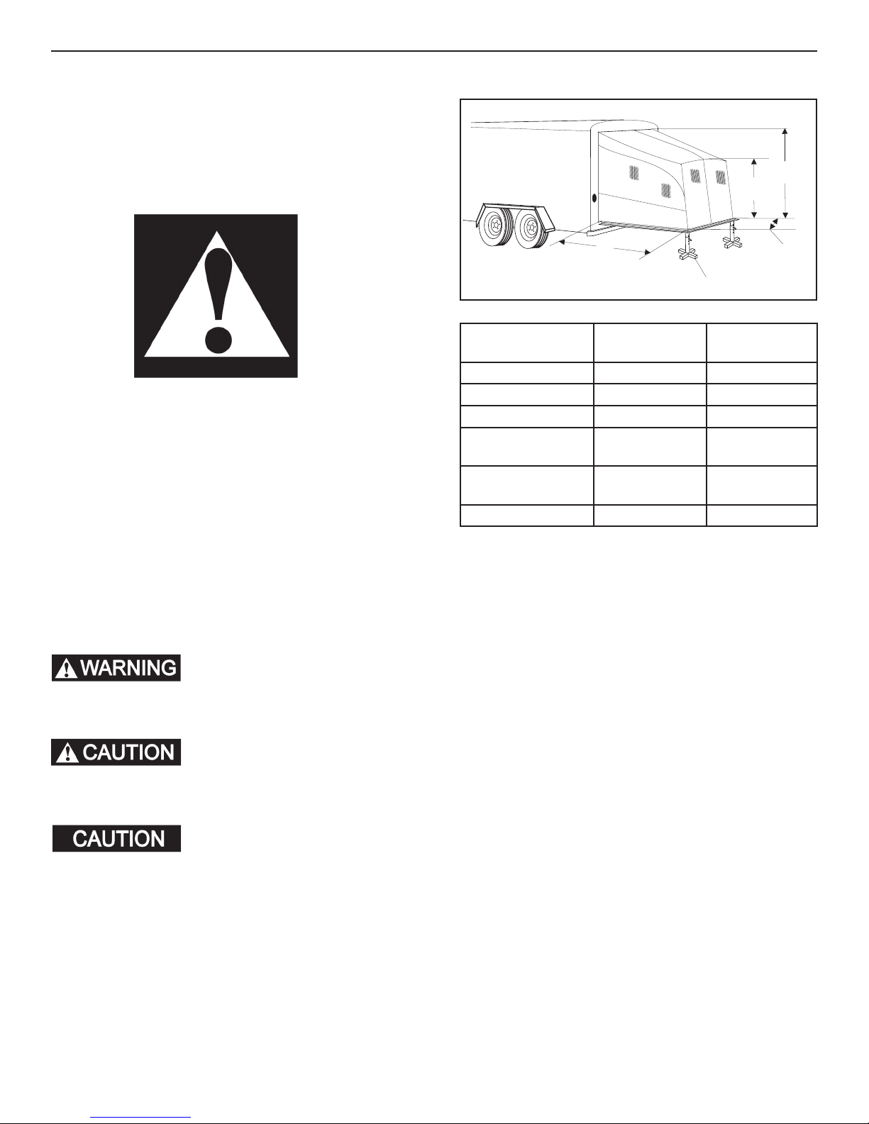
SPECIFICATIONS
C
B
A
E
Model 954086.000
Min./Max.
A = Length 81-1/2" 88-1/2"
B = Front (Height) 75" 75"
C = Rear (Height) 79-1/2"/86-1/2" 86-1/2"/96-1/2"
D = Expandable
Rear Width
E = Ramp Stand
*Range
Capacity 1,200 lbs. 1,200 lbs.
86"/91" 91"/99"
16"/28" 16"/28"
954091.000
Min./Max.
D
UNDERSTAND SIGNAL WORDS
A signal word , WARNING OR CAUTION is used
with the safety-alert symbol. They give the level
of risk for potential injury.
indicates a potentially hazard-
ous situation which, if not avoided, could result
in death or serious injury.
indicates a potentially hazard-
ous situation which, if not avoided, may result in
minor or moderate injury.
used without the safety alert
symbol indicates, a potentially hazardous situation which, if not avoided, may result in property
damage.
Read and follow all safety information and instructions.
* Ramp stand adjusts with one inch increments.
2
X TEND A-ROOMTM INSTALLATION AND OPERATION SUPPLEMENT
GENERAL INSTRUCTIONS
These instructions must be read and understood before installation of this kit. Modication of this product can be extremely hazardous and could result in personal injury and/or
property damage.
The X Tend A-Room TM is designed to be installed around
the loading ramp opening of a cargo type trailer, allowing
users to enjoy the extra living space.
Product features and specications as described or illustrated are subject to change without notice. Installation
methods not described in this manual must have written
approval from Dometic, LLC.
Important: Read the entire Installation and Operating
Instructions carefully before starting the installation.
Contents:
(1) Instructions (4) Snap Fasteners
(1) Roll of Hook Tape (1) Fabric Assembly.
(1) Oxford Storage Bag (4) Ramp Floor J-Hooks
(1) Ctr Roof Pole Assm. (1) Front Pole Assm.
(2) Ramp Stand (1) Rear Pole Assm.
(1) Pole Storage Bag (4) #8 x 3/4" Screws
(1) Tread Plate Set
Tools Required:
Power Drill/Screwdriver
INSTALLATION
Park the trailer on at and level surface for the initial installation. This will insure that the X Tend A-Room TM will be
straight and square with the trailer.
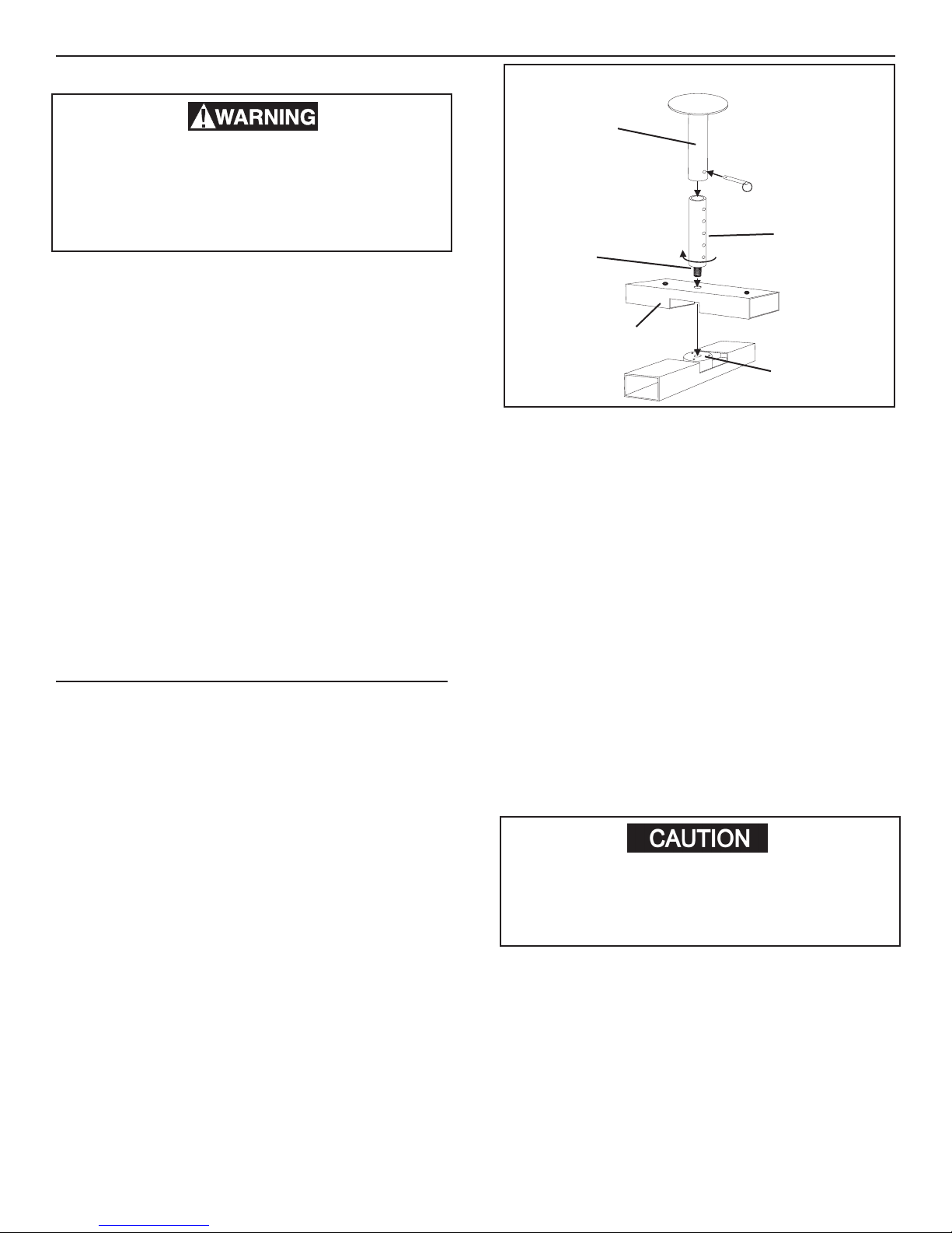
A. Ramp Stand Assembly
1. Find the channel with a threaded nylon insert .
Place the threaded nylon insert with the notch
up.
2. Place the second channel with a hole across the
rst channel with the hole on top forming the letter
"X".
3. The stand pole with the stud bolt is screwed into the
nylon insert through the channel with the hole. This
should be tightened so there is no movement.
4. The top stand pole slides on the bottom assembly
and is locked in place with the ball pin. See Fig.
1.
Note: Each ramp stand has a rubber coating on the top
plate to prevent scratching of the ramp. There is also a
tread plate set included to protect ramp's surface where
ramp rests on ramp stands.
FIG. 1
Top Stand
Pole
Ball Pin
Stand Pole
Stud Bolt
Channel With
Hole
Lower Stand
Pole
Channel With
Nylon Insert
B. Ramp Preparation
1. Place ramp stands at the approximate positions for
each corner of the ramp. If terrain is not level, add
leveling blocks as necessary to even out weight
and level to ramp stands.
2. Pull the ball pin and raise/lower each ramp stand
to the approximate position where the ramp will
be approximately level. Align stand extension with
the closest hole in the base and replace the stand
pin.
3. Lower the ramp and move the ramp stands in position under ramp's door frame corners, where ramp
is strongest. Mark this spot. Screw tread plates,
one on each side, onto the ramp where ramp stand
location had been marked. Then place stands under
door frame corners where tread plates are located.
Tread plates are provided to prevent scratching of
ramp surface with ramp stand tops.
4. To reduce the possibility of ramp stands accidentally getting kicked over insert tent stakes through
each of the 2 holes on both ramp stands.
Failure to place stands under ramp's door
frame could cause damage to door's outer
berglass surface when ramp is placed under
load.
C. Description Of Pole Assemblies
There are 3 pole assemblies:
Center Roof Pole Assembly•
Rear/Frame Pole Assembly•
Front Pole Assembly•
Some pole assemblies are shock corded; all are num-
bered with stickers to identify matching assembly poles
and all are painted to make it easier to identify pole
assemblies: Center roof pole assembly is white, front
pole assembly is white, and rear/frame pole assembly
is black. See Figs. 2, 3 & 4.
3
 Loading...