

Dometic 9 Series, RMLT 943 Series, RMLT 933 Series, RMLT9330, RMLT9331 Installation Manual
...Page 1
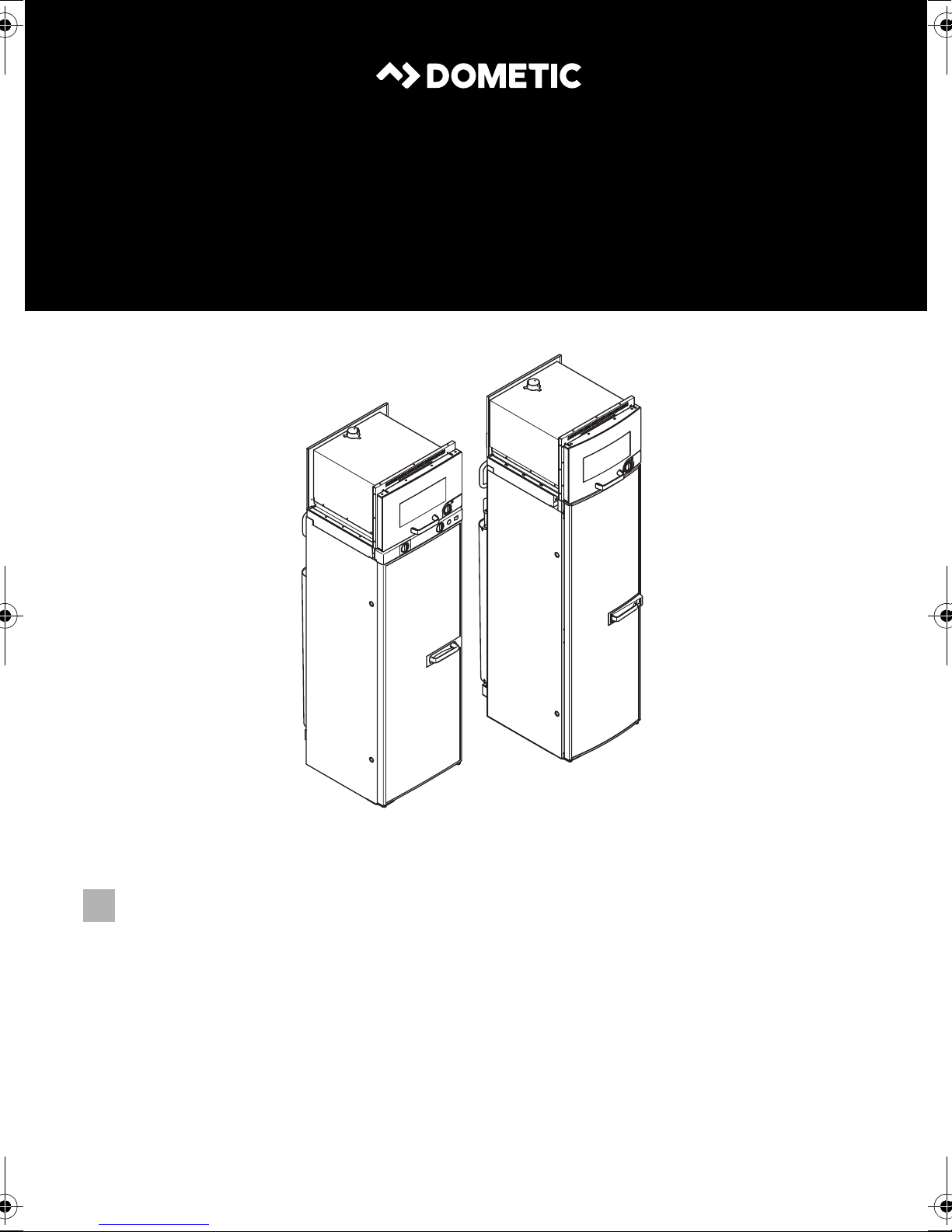
RMLT 943x
RMLT 933x
EN
REFRIGERATION
9 SERIES
RMLT9330, RMLT9331, RMLT9335
RMLT9430, RMLT9431, RMLT9435
Absorber-refrigerator with oven
Installation Manual
Page 2
Page 3
EN
RMLT9xxx
Please read this instruction manual carefully before installation and first
use, and store it in a safe place. If you pass on the product to another
person, hand over this instruction manual along with it.
NOTE
You can find details on the operation in the manual.
I
Table of contents
1 Explanation of symbols. . . . . . . . . . . . . . . . . . . . . . . . . . . . . . . . . . . . . . . . . . .4
2 Safety instructions . . . . . . . . . . . . . . . . . . . . . . . . . . . . . . . . . . . . . . . . . . . . . . .4
3 Scope of delivery . . . . . . . . . . . . . . . . . . . . . . . . . . . . . . . . . . . . . . . . . . . . . . .6
4 Accessories . . . . . . . . . . . . . . . . . . . . . . . . . . . . . . . . . . . . . . . . . . . . . . . . . . . .7
5 Intended use . . . . . . . . . . . . . . . . . . . . . . . . . . . . . . . . . . . . . . . . . . . . . . . . . . .7
6 Installing the refrigerator-oven combination . . . . . . . . . . . . . . . . . . . . . . . . . .8
7 Connecting the refrigerator-oven combination . . . . . . . . . . . . . . . . . . . . . 27
8 Technical data . . . . . . . . . . . . . . . . . . . . . . . . . . . . . . . . . . . . . . . . . . . . . . . . 36
3
Page 4
EN
Explanation of symbols RMLT9xxx
1 Explanation of symbols
WARNING!
!
Safety instruction: Failure to observe this instruction can cause fatal or
serious injury.
CAUTION!
Safety instruction: Failure to observe this instruction can lead to injury.
!
NOTICE!
A
Failure to observe this instruction can cause material damage and impair
the function of the product.
NOTE
Supplementary information for operating the product.
I
2 Safety instructions
The manufacturer accepts no liability for damage in the following cases:
• Faulty assembly or connection
• Damage to the product resulting from mechanical influences and excess voltage
• Alterations to the product without express permission from the manufacturer
• Use for purposes other than those described in the operating manual
4
Page 5
EN
RMLT9xxx Safety instructions
2.1 General safety
WARNING!
!
• Never open the absorber unit. It is under high pressure and can cause
injury if it is opened.
• Ensure clean and residue-free handling if silicon sealant or similar is
used. There is a risk of fire if silicone filaments come into contact with
hot parts or naked flames.
• Do not operate the device if it is visibly damaged.
• If the AC power cable for this device is damaged, it must be replaced
by the manufacturer, customer service or a similarly qualified person in
order to prevent safety hazards.
• Never use a naked flame to check the device for leaks.
• This device may only be repaired by qualified personnel. Inadequate
repairs may cause serious hazards.
• Only use propane or butane gas (not natural gas).
• Always operate the device at the pressure shown on the type plate.
Use a DIN-DVGW-approved pressure regulator with a fixed setting in
accordance with DIN EN 12864.
• Dismantle all doors for the disposal of the old device and leave the
shelves in the device to prevent accidental enclosure and suffocation.
!
CAUTION!
• Danger of crushing! Do not put your fingers into the hinge.
• Before starting the device, ensure that the power supply line and the
plug are dry.
5
Page 6
EN
Scope of delivery RMLT9xxx
NOTICE!
A
• Only hold the device at the body of the refrigerator during transport.
Never hold the device on the oven, the cooling fins, the gas pipes, the
door or the control panel.
• Make sure that the refrigerator circuit is not damaged during transpor-
tation. The refrigerant in the refrigerator circuit is highly flammable.
In the event of any damage to the refrigerator circuit:
– Avoid naked flames and sparks.
– Air the room well.
• Do not install the device near naked flames or other heat sources
(heaters, direct sunlight, gas ovens etc.).
• Danger of overheating!
Always ensure sufficient ventilation so that the heat generated during
operation can dissipate. Make sure that the device is sufficiently far
away from walls and other objects so that the air can circulate.
• Check that the voltage specification on the type plate is the same as
that of the power supply.
• Do not open the refrigerant circuit under any circumstances.
• Only use the AC connection cable supplied to connect the device to
the AC mains.
• Only use cables with a suitable size.
• Never pull the plug out of the socket by the connection cable.
• The device may not be exposed to rain.
3Scope of delivery
• Refrigerator-oven combination
• Ice-cube tray
• Operating manual
• Installation manual
6
Page 7
EN
RMLT9xxx Accessories
4Accessories
Available as accessories (not included in the scope of delivery):
Description
Fan kit for boosting the cooling capacity at high ambient temperatures
Ventilation grille
Winter cover for the ventilation grille
Truma AK3 roof flue
Truma flue pipe
Divider, bottle finger (RMLT9430/9431/9435 only)
Shelf with safety edges (RMLT9430/9431/9435 only)
Door shelf locking
Bottle holder for door shelf locking
Shelf locking
All the accessories are available from specialist dealers. If you have any questions,
please contact the dealer or your service partner directly.
5 Intended use
This refrigerator-oven combination is designed for installation in caravans or motorhomes.
The refrigerator is only suitable for cooling, freezing and storing foodstuffs. The
refrigerator is not intended for the proper storage of medicine.
The refrigerator is designed to be operated on a DC power supply and an AC socket
and can be independently powered by liquid gas (propane or butane). The refrigerator may not be run on natural gas or city gas.
The oven is only suitable for cooking and baking foodstuffs.
The oven is designed to be run on liquid gas (propane or butane). The oven may not
be run on natural gas or city gas.
7
Page 8
EN
Installing the refrigerator-oven combination RMLT9xxx
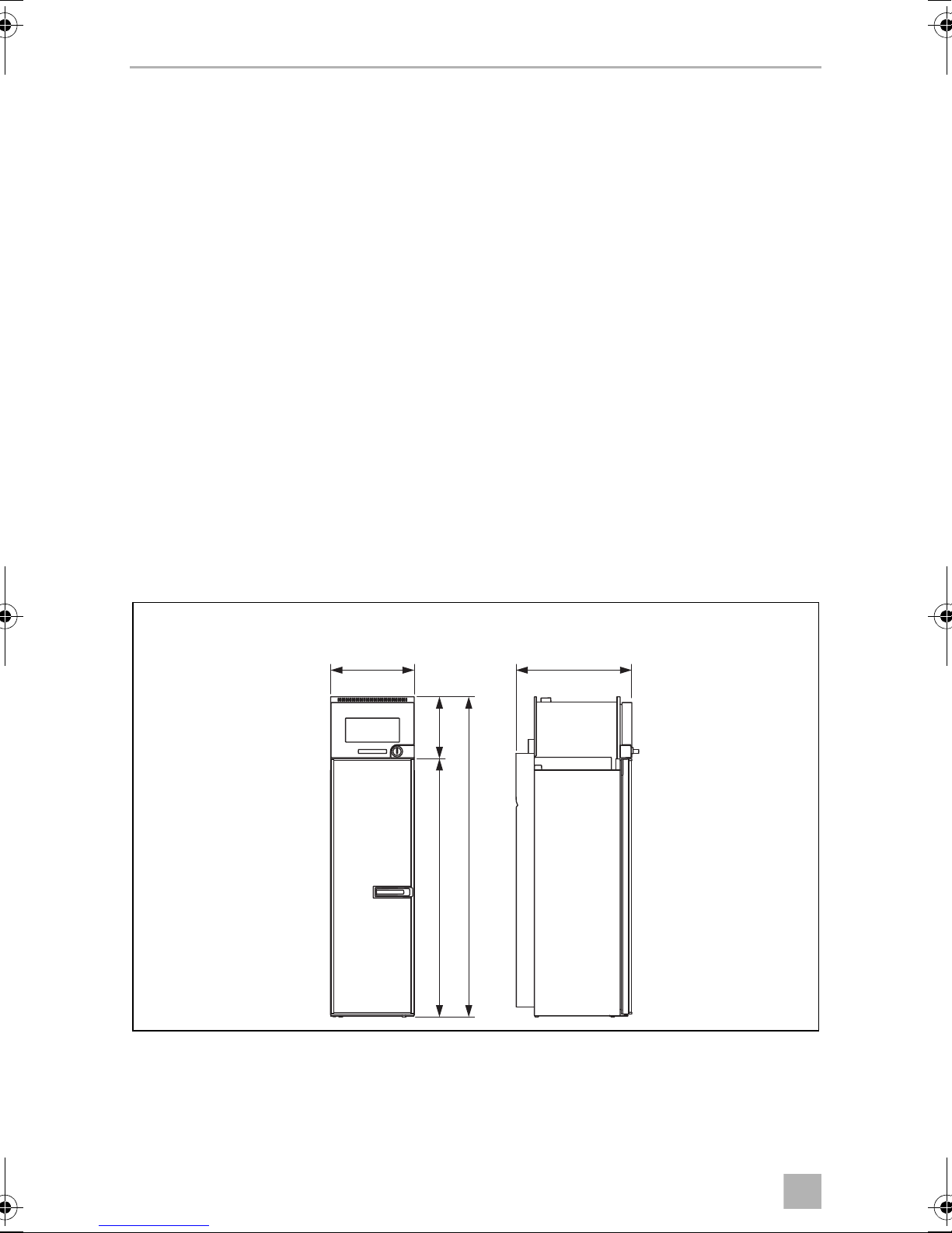
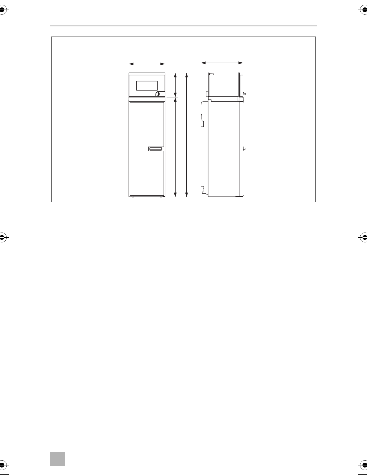
420 mm 615 mm
1605 mm
312 mm1293 mm
RMLT9330, RMLT9331, RMLT9335
1
6 Installing the refrigerator-oven
combination
6.1 Preparing the installation
When installing the refrigerator-oven combination, note the following:
• To enable the refrigerant to circulate properly, the refrigerator may not exceed an
angle of 3°.
To do this, park the vehicle on a level surface and check to see if the ice-cube tray
is flat in the refrigerator.
• The refrigerator-oven combination must be installed so that it is easily accessible
for service work, easy to de-install and install, and easily removed from the
vehicle.
• The distance between the refrigerator-oven combination and the rear wall must
be min. 15 mm – max. 25 mm.
• The refrigerator-oven combination must be installed in a recess so that it stands
firm when the vehicle is in motion. Note the following dimensions here
(HxWxD inmm):
– RMLT9330/9331/9335: 1605 x 420 x 615 (fig. 1)
8
Page 9
EN
RMLT9xxx Installing the refrigerator-oven combination
2
RMLT9430, RMLT9431, RMLT9435
468 mm
312 mm1293 mm
1605 mm
555 mm
– RMLT9430/9431/9435: 1605 x 468 x 555 (fig. 2)
9
Page 10

EN
Installing the refrigerator-oven combination RMLT9xxx
6
2
3
4
5
1
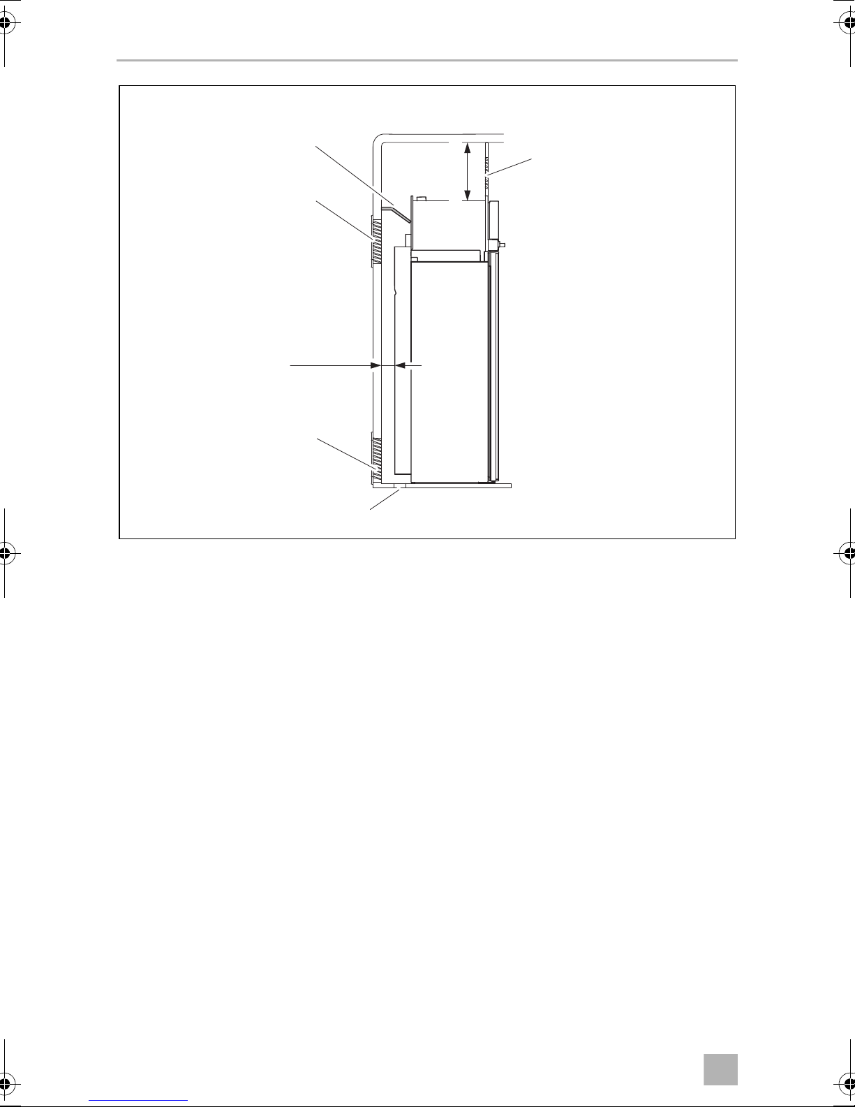
10 mm
≥ 170 mm
min.15 mm –
max. 25 mm
3
• The outer wall must be fitted with an air inlet vent (fig. 3 1) and an outlet vent
(fig. 3 2) with ventilation grilles so that the heat generated can be easily
released to the outside:
– Air inlet vent: Fit the ventilation grille as flush as possible to the floor of the
installation niche with a minimum cross-section of 400 cm².
– Outlet vent: fit as far above the refrigerator as possible.
10
Page 11

EN
RMLT9xxx Installing the refrigerator-oven combination
≥ 1050 ≥ 250
< 1050
< 250
4
– The distance between the air inlet and outlet vents must be at least 1050 mm
(fig. 4).
• Fit a heat conduction plate (fig. 3 3, page 10) above the refrigerator so that the
heat does not accumulate in the vehicle.
• If the ventilation grille of the air inlet vent cannot be installed flush to the ground,
an additional inlet vent (fig. 3 6, page 10) must be provided in the floor for
releasing leaked gas.
• The distance between the top of the oven and the ceiling must be at least
170 mm (fig. 3, page 10).
• If a roof flue (fig. 3 4, page 10) is being used: Fit a detachable panel (fig. 3 5,
page 10) above the oven so that you can always reach the flue pipe.
11
Page 12
EN
Installing the refrigerator-oven combination RMLT9xxx
7
6
2
3
1
min.15 mm –
max. 25 mm
≥ 170 mm
5
• If you do not have a roof flue: Fit a panel with a ventilation grille (fig. 5 7) above
the oven.
• The distance between the top of the oven and the flue outlet of the roof flue must
be between 250 mm and 1500 mm (fig. 4, page 11).
12
Page 13

EN
RMLT9xxx Installing the refrigerator-oven combination
15 – 25 mm
> 25 mm
> 25 mm
6
• Too large a gap between the refrigerator-oven combination and rear wall leads
to poor performance and increases the power consumption of the refrigerator.
Reduce the space behind the refrigerator-oven combination to create adequate
air inlet and outlet ventilation (fig. 6).
• The refrigerator-oven combination must not be installed at the side of the air inlet
and outlet vents as this leads to poor performance and increases the power
consumption of the refrigerator.
• The air inlet and outlet vents must not be covered by vehicle parts (such as an
open door or by installing accessories such as bicycle racks) while operating.
• Install the refrigerator-oven combination so that it is protected from excessive
heat, as this leads to poor performance and increases the power consumption of
the refrigerator.
• The electrical installation must comply with national and local regulations.
European standards: EN 60335-1, EN 60335-2-24, EN 1648-1 and EN 1648-2.
• The gas installation must comply with national and local regulations.
European standard: EN 1949.
• The refrigerator-oven combination must be installed in a draught-proof location
in accordance with EN 1949, see chapter “Installing the refrigerator-oven combination in a draught-free location” on page 14.
13
Page 14

EN
Installing the refrigerator-oven combination RMLT9xxx
1
7
6.2 Installing the refrigerator-oven combination in a
draught-free location
Gas-powered refrigerators in caravans or motorhomes must be installed in a
draught-free location according to EN 1949. This means that the combustion air is
not extracted from the interior and the exhaust fumes are prevented from directly
entering the living space.
A suitable seal must be fitted between the rear panel of the refrigerator-oven combination and the interior of the vehicle.
WARNING! Fire hazard!
!
The manufacturer recommends using a flexible seal to ease removal and installation
for maintenance purposes.
• Do not use flammable materials such as silicone sealants, foam or
similar for the draught-proof installation.
• Use materials that are resistant to temperatures of up to 200 °C in the
vicinity of the oven.
➤ Attach the sealing lips (fig. 7 1) to a stop rail behind the refrigerator-oven com-
bination, for example, by using an adhesive.
➤ When installing, push the refrigerator-oven combination against the stop rails
with the sealing lips. This then seals the space behind the refrigerator to the interior of the vehicle.
14
Page 15

EN
RMLT9xxx Installing the refrigerator-oven combination
8
6.3 Making air inlet and outlet vents
NOTE
I
➤ Make an air inlet vent and an air outlet vent in the outer wall with the size of
410 mm x 249 mm. When doing so, observe the information, see chapter “Preparing the installation” on page 8.
If the ventilation grille of the air inlet vent cannot be installed flush with the floor of the
niche, you need to install an inlet vent in the floor:
➤ Make a n air inle t vent in the fl oor ( fig. 3, page 10 6) behind the refrigerator-oven
combination near the gas burner.
At high ambient temperatures, the refrigerator can only provide its
maximum cooling capacity if the optimum ventilation has been
provided.
➤ Shield the end of the opening with a deflector to prevent sludge or dirt from get-
ting inside while driving (fig. 8).
15
Page 16

EN
Installing the refrigerator-oven combination RMLT9xxx
2
3
1
5
3
4
1
2
≥ 170 mm
≤ 1300 mm
Ø65
Ø55
≥ 10°
Ø3,5
9
6.4 Oven ventilation using a roof flue
NOTICE!
A
• Use a Truma AK 3 roof flue and Truma flue pipes. These have been
tested and approved for use.
• Materials must not be located near the roof flue and flue pipe which
are unsuitable for temperatures of above 120 °C.
• Lay the flue duct so that it rises gradually. The installation height of the
flue pipe between the top of the oven and the air outlet on the roof
flue must be at least 200 mm. A maximum of 1500 mm is possible.
• Keep the surrounding walls and components at a distance of at least
50 mm.
Proceed as follows (fig. 9):
Alternatively, you can use a worm gear hose clamp.
➤ Make a round hole with a diameter of 60 mm in the roof.
➤ Secure the roof flue (1) in the hole.
➤ Slide the flexible flue pipe (2) up into the roof flue.
➤ Insert the bottom end of the flue pipe (4) onto the end of the flue outlet (5).
➤ Attach the flue pipe using the screws which were supplied with the roof flue (3).
➤ Fit a detachable panel (fig. 3, page 10 5) above the oven.
16
Page 17

EN
RMLT9xxx Installing the refrigerator-oven combination
1
0
6.5 Interior oven ventilation (oven without roof flue)
If you are providing the ventilation and flue duct in the vehicle interior, the supply of
fresh air must not be obstructed. Make ventilation holes that allow fresh air to enter
(safety ventilation according to EN 721). A combination of roof and wall ventilation
holes is possible.
Ventilation holes in the lower part may not be more than 100 mm above the interior
floor. The ventilation holes must not be closed under any circumstances. Keep the
grids and covers clean and free of dust.
➤ Make ventilation holes in the vehicle interior with a total cross-section of at least
100 cm
➤ Make one or more ventilation openings above the oven with a total cross-section
of at least 150 cm
2
.
2
.
➤ Fit a panel above the oven and a ventilation grille in the panel with
468 mm x 90 mm (fig. 0 1).
✓ Fresh air enters through ventilation slots into the oven under the door, is heated
and escapes from the oven through ventilation slots in the top of the door
(fig. 0).
NOTE
Check and clean the ventilation holes regularly.
I
17
Page 18

EN
Installing the refrigerator-oven combination RMLT9xxx
1
2
3
4
1
3
2
4
LS230 LS330
a
b
6.6 Installing the ventilation grille
No. in
fig. a
1 Installation frame
2 Ventilation grille
3 Winter cover
4Slider
Description
LS230
LS330
➤ Ensure the installation frame is water resistant (fig. b).
18
Page 19

EN
RMLT9xxx Installing the refrigerator-oven combination
c
LS230
LS330
1.
2.
3.
d
LS230
LS330
➤ Insert the installation frame and screw it down tightly (fig. c).
➤ Fit the ventilation grille (fig. d).
➤ Insert the slider and lock the ventilation grille with it (fig. d).
19
Page 20

EN
Installing the refrigerator-oven combination RMLT9xxx
1
2
3
4
e
6.7 Installing the flue duct (fig. e)
NOTE
I
The flue duct is installed at the factory. Follow these steps when you have removed
the flue duct and want to reinstall it:
➤ Place the T-piece (1) on the adaptor (2) and the flue pipe (3).
➤ Direct the T-piece at an angle of 45° towards the rear wall.
➤ Attach the T-piece, adaptor and flue pipe with a screw (4).
Do not install an additional flue stack, as this leads to poor performance
and increases the power consumption of the refrigerator.
20
Page 21

EN
RMLT9xxx Installing the refrigerator-oven combination
1
2
f
6.8 Securing the refrigerator-oven combination
CAUTION!
!
I
Only drill through the receptacles provided, otherwise foamed
components, including cables, can be damaged.
NOTE
Attach the side walls or the attached strips so that the screws are tight,
even when under increased loads (while driving).
Proceed as follows (fig. f):
➤ Move the refrigerator-oven combination into its final position.
➤ Fasten the four screws (1) through the four plastic washers (2) in the sides of the
refrigerator, and further into the wall.
21
Page 22

EN
Installing the refrigerator-oven combination RMLT9xxx
g
1.
2.
3.
RMLT9431
RMLT9435
h
i
6.9 Changing the door hinges (RMLT943x only)
To change the refrigerator door hinges, proceed as follows:
➤ Remove the control panel.
RMLT9430
3.
2.
1.
– RMLT9430: Unscrew the dials carefully and loosen the screws, fig. g
– RMLT9431/9435: Open the refrigerator door and undo the screws under-
neath the control panel, fig. h
➤ Undo the hinge screw on the top door hinge and keep it in a safe place (fig. i).
22
Page 23

EN
RMLT9xxx Installing the refrigerator-oven combination
j
k
2x
l
2.
1.
➤ Lift up the door and remove it (fig. j).
2x
➤ Undo the two screws on the door lock and remove the door lock (fig. k).
➤ Place the door lock on the other side again and tighten it with the two screws
(fig. l).
23
Page 24

EN
Installing the refrigerator-oven combination RMLT9xxx
n
m
o
➤ Undo the hinge pin (fig. m) and position it on the other side (fig. n).
➤ Turn the door by 180° (fig. o).
➤ Place the door on the hinge pin.
➤ Tighten the hinge screw at the top door hinge.
➤ Replace the control panel and screw it down tightly.
24
Page 25

EN
RMLT9xxx Installing the refrigerator-oven combination
448
194,5
1216
46
≤ 2,5
≤ 2,5
≤ 2,5
402
189
1270,5
49583,5
402
189
1270,5
49583,5
AB
RMLT943xRMLT933x
p
6.10 Putting on the door panel
NOTICE! Beware of damage
A
Only ever lay the refrigerator on its side and never on its back. Otherwise
the unit may be damaged.
Note the dimensions of the door panel (fig. p).
25
Page 26

EN
Installing the refrigerator-oven combination RMLT9xxx
1.
3.
2.
A B
q
Proceed as follows (fig. q):
➤ Remove the door trim carefully. It is only stuck on and held by small hooks (A).
➤ Slide the new panel into the opening (B).
➤ Replace the door trim (B).
✓ The door trim is secure once it clicks into place.
If you have laid it on its side to insert the panel:
➤ Wait a few minutes before you switch on the refrigerator.
26
Page 27

EN
RMLT9xxx Connecting the refrigerator-oven combination
7 Connecting the refrigerator-oven
combination
7.1 Connecting to the gas supply
NOTICE!
A
• This refrigerator-oven combination may only be connected to the
gas supply by a specialist in accordance with the applicable
guidelines and standards.
• Only use cylinders of propane or butane gas (not natural gas or city
gas) with an approved pressure reduction valve and suitable head.
Compare the pressure information on the type plate with the
pressure information on the pressure regulator on the propane or
butane gas cylinder.
• Only operate the refrigerator-oven combination at the pressure
shown on the type plate.
• Please note the pressures which are permitted in your country. Use a
DIN-DVGW-approved pressure regulator with a fixed setting:
– The following applies for Germany: DIN EN 12864.
– The following applies for Europe: EN 732 and EN 1949.
NOTE
I
It must be possible to shut off the refrigerator-oven combination from the gas line
separately by means of a shut-off device. The shut-off device must be easily
accessible.
The refrigerator-oven combination is equipped for a connection
pressure of 30 mbar. Use a 50/30 mbar pressure regulator when connected to a 50 mbar system.
27
Page 28

EN
Connecting the refrigerator-oven combination RMLT9xxx
SW 17
SW 14
r
➤ Connect the refrigerator-oven combination securely by hand to the gas supply
(fig. r).
The following applies for Europe: Use a cutting ring fitting in accordance with
EN 1949.
A hose connection is not permitted.
➤ Have a leak test and a flame test performed in accordance with EN 1949 by an
authorised specialist.
Ensure you are issued with a certificate of inspection.
28
Page 29

EN
RMLT9xxx Connecting the refrigerator-oven combination
7.2 Connecting to DC and AC
NOTICE!
A
I
• The electrical installation and repairs may only be performed by a
specialist in accordance with the applicable regulations and
standards.
• According to EN 1648-1, the respective negative and positive cables
of the DC connections for heating cartridge and lighting may not be
joined with one another in a caravan. This can cause electrical
interference or damage to electrical components.
• The inverter may only be connected by a specialist.
NOTE
• The mains socket must be easily accessible so that you can unplug
the power cord if required, thereby disconnecting the refrigerator
from the power.
• The plug of the AC connection cable must not be cut off.
• The connection cables must be laid so that they do not come in
contact with hot parts of the unit/burner or oven or with sharp
edges.
• Changes to the internal electrical installation or the connection of
other electrical components (e.g. extra third party fans) to the
internal wiring of the refrigerator will void the E1/CE approval and
any claims from the guarantee and product liability.
29
Page 30

EN
Connecting the refrigerator-oven combination RMLT9xxx
s
rt
+
1
2
15
br
87
85 86
30
14
ws
br
ws
ws
_
3
4
5
_
sw
bl
+
gn
ws
br
ge
ws
+
br
6
br
78
ws
rt
sw
br
12
bl
sw
6a
6b
4a
4b
ws
2a
br
2b
10
rt
11
5b
5a
3b
3a
1b
1a
ge
gn
br
br
bl
bl
br br
bl bl
10
ge/gn
ge
E
L
F
G
9
N
10
13
EN
ge/gn
V85
br
br
ge/gn
bl br ge gn rt sw ws
Blue Brown Yellow Green Red Black White
30
Page 31

EN
RMLT9xxx Connecting the refrigerator-oven combination
➤ Connect the RMLT9330/9430 refrigerators as follows (fig. s, page 30).
Item Description
1 Positive cable of the heating cartridge
2 Earth cable of the heating cartridge
3 Terminal strip for the DC power supply of the heating cartridge
4 Earth cable of the heating cartridge
5 Positive cable of the lighting
6 Terminal strip for connecting the lighting
7 LED lighting
8 Switch for the LED lighting
9 AC power connection cable
10 Housing earth (upper section)
11 Thermal power adapter
12 Galvanometer
13 AC heating cartridge
14 Relay 30 A
15 DC heating cartridge
31
Page 32

EN
Connecting the refrigerator-oven combination RMLT9xxx
t
1
10
2
NL
L
N
13
3
LLNN
IN OUT
AC
TO GV 12VDCOUT
TO FC
TOP
4
12
ABS
9
EN
11
HE OUT 12 VDC HE IN
(-)
S+D+(+)
(+)
brbrbrws
(-)
(-)
(+)
6
8
A
BCDE FG
br rt sw ws
Brown Red Black White
7
5
swrt
32
Page 33

EN
RMLT9xxx Connecting the refrigerator-oven combination
➤ Connect the RMLT9331/9335/9431/9435 refrigerators as follows (fig. t,
page 32):
Item Description
1 AC heating cartridge
2 AC power connection cable
3 Earth AC power
4 Ionisation
5 Ignition
6Burner
7 DC heating cartridge
8 LED lighting
9 Gas input
10 Gas output
11 Gas valve
12 DC power outlet
13 Gas valve supply line
A Optional connections to DC power outlet
B Negative terminal (–) DC permanent supply for electronics
C Positive terminal (+) DC permanent supply for electronics
D Connection D+
E Connection S+
F Positive cable of the heating cartridge
G Earth cable of the heating cartridge
33
Page 34

EN
Connecting the refrigerator-oven combination RMLT9xxx
RMLT93…
RMLT94…
u
AC power
➤ Connect the refrigerator with the mains plug to an AC socket.
DC power
NOTE
I
Please note the following cable sizes:
– < 6m (interior): 6mm
– > 6 m (interior): 10 mm
– Connections D+ and S+: 1 mm
– Cable fed via drawbar (caravans only): 2.5 mm
• The supply line to the DC heating cartridge must be protected by
20 A.
• RMLT9330/9430: The supply line to the lighting must be
protected by 2 A.
• RMLT9331/9335/9431/9435: The supply line to the electronic
control unit must be protected by 2 A.
2
2
2
2
➤ Connect the DC heating cartridge with the shortest possible cable.
➤ Run the cable to the DC heating cartridge via a relay controlled by an ignition
socket to prevent the battery from completely discharging if the engine is
switched off accidentally (fig. u).
34
Page 35

EN
RMLT9xxx Connecting the refrigerator-oven combination
➤ RMLT9330/9430 only: Connect a 12 V continuous supply to the connection
for lighting.
➤ RMLT9331/9335/9431/9435 only: Connect a 12 V continuous supply to
the connection for electronic control unit.
D+ (RMLT9335/9435 only)
In automatic mode, the refrigerator selects the most favourable mode available. The
refrigerator is only operated with direct current when the vehicle engine is running.
The electronics of the refrigerator uses the signal D+ from the light system to detect
the running engine.
➤ Connect the D+ connection to the controls (fig. t D, page 32) with the
respective terminal of the vehicle.
7.3 S+ (RMLT9335/9435 only)
In automatic mode, the refrigerator is first powered with DC power from
the vehicle's own solar system. The refrigerator electronics uses the S+ signal of the
solar charge controller to detect a solar system. The solar charge controller must
have an AES output.
➤ Connect the S+ connection on the controller (fig. t E, page 32) to the
respective terminal of the solar charge controller.
Suitable solar charge controllers are available from specialist dealers.
The manufacturer recommends, for example:
• Büttner MT 300-S
(www.buettner-elektronik.de)
• Votronic MPP 240 Duo Digital
(www.votronic.de)
35
Page 36

EN
Technical data RMLT9xxx
1
8 Technical data
RMLT9330 RMLT9331 RMLT9335
Voltage: 230 Vw/50 Hz
12 Vg
Gross capacity: 134 l
Freezer compartment: 12 l
Gross capacity
(excluding freezer
compartment):
Net capacity: 129 l
Net capacity
(excluding freezer
compartment):
Power consumption: 170 W (230 Vw)
Power consumption: 3.2 kWh/24 h (230 Vw)
340 Ah/24 h (12 Vg)
Gas consumption: 380 g/24 h
Oven gas consumption: 80 g/1 h
Climatic class: SN
Noise emission: 0 dB(A)
138.5 l
133.5 l
170 W (12 Vg)
Ignition: Manual Automatic Automatic
Power choice: Manual Manual Automatic
Dimensions: fig. 1, page 8
Weight: 52 kg
Inspection/certification:
NOTE
You can obtain the CE declaration of conformity at Dometic.
I
36
Page 37

EN
RMLT9xxx Technical data
1
RMLT9430 RMLT9431 RMLT9435
Voltage: 230 Vw/50 Hz
12 Vg
Gross capacity: 146 l
Freezer compartment: 12 l
Gross capacity
(excluding freezer
compartment):
Net capacity: 142 l
Net capacity
(excluding freezer
compartment):
Power consumption: 170 W (230 Vw)
Power consumption: 3.2 kWh/24 h (230 Vw)
340 Ah/24 h (12 Vg)
Gas consumption: 380 g/24 h
Oven gas consumption: 80 g/1 h
Climatic class: SN
Noise emission: 0 dB(A)
151 l
148 l
170 W (12 Vg)
Ignition: Manual Automatic Automatic
Power choice: Manual Manual Automatic
Dimensions: fig. 2, page 9
Weight: 52 kg
Inspection/certification:
NOTE
You can obtain the CE declaration of conformity at Dometic.
I
37
Page 38

Page 39

Page 40

GERMANY
Dometic WAECO International GmbH
Hollefeldstraße 63 · D-48282 Emsdetten
+49 (0) 2572 879-0 · +49 (0) 2572 879-300
Mail: info@dometic-waeco.de
dometic.com
AUSTRALIA
Dometic Australia Pty. Ltd.
1 John Duncan Court
Varsity Lakes QLD 4227
1800 212121
+61 7 55076001
Mail: sales@dometic.com.au
AUSTRIA
Dometic Austria GmbH
Neudorferstraße 108
A-2353 Guntram sdorf
+43 2236 908070
+43 2236 90807060
Mail: info@dometic.at
BENELUX
Dometic Branch Office Belgium
Zincstraat 3
B-1500 Halle
+32 2 3598040
+32 2 3598050
Mail: info@dometic.be
BRAZIL
Dometic DO Brasil LTDA
Avenida Paulista 1754, conj. 111
SP 01310-920 Sao Paulo
+55 11 3251 3352
+55 11 3251 3362
Mail: info@dometic.com.br
DENMARK
Dometic Denmark A/S
Nordensvej 15, Taulov
DK-7000 Fredericia
+45 7558 5966
+45 75586307
Mail: info@dometic.dk
FINLAND
Dometic Finland OY
Mestarintie 4
FIN-01730 Vantaa
+358 20 7413220
+358 9 7593700
Mail: info@dometic.fi
FRANCE
Dometic SAS
ZA du Pré de la Dame Jeanne
B.P. 5
F-60128 Plailly
+33 3 44633525
+33 3 44633518
Mail : vehiculesdeloisirs@dometic.fr
HONG KONG
Dometic Group Asia Pacific
Suites 2207-11 · 22/F · Tower 1
The Gateway · 25 Canton Road,
Tsim Sha Tsui · Kowloon
+852 2 4611386
+852 2 4665553
Mail: info@waeco.com.hk
HUNGARY
Dometic Zrt. Sales Office
Kerékgyártó u. 5.
H-1147 Budapest
+36 1 468 4400
+36 1 468 4401
Mail: budapest@dometic.hu
ITALY
Dometic Italy S.r.l.
Via Virgilio, 3
I-47122 Forlì (FC)
+39 0543 754901
+39 0543 754983
Mail: vendite@d ometic.it
JAPAN
Dometic KK
Maekawa-Shibaura, Bldg. 2
2-13-9 Shibaura Minato-ku
Tokyo 108-0023
+81 3 544 5 3333
+81 3 5445 3339
Mail: info@dometic.jp
MEXICO
Dometic Mx, S. de R. L. d e C. V.
Circuito Médicos No. 6 Local 1
Colonia Ciudad Satélite
CP 53100 Naucalpan de Juárez
Estado de México
+52 55 5374 4108
+52 55 5393 4683
Mail: info@dometic.com.mx
NETHERLANDS
Dometic Benelux B.V.
Ecustraat 3
NL-4879 NP Etten-Leu r
+31 76 5029000
+31 76 5029019
Mail: info@dometic.nl
NEW ZEALAND
Dometic New Zealand Ltd.
PO Box 12011
Penrose
Auckland 1642
+64 9 622 1490
+64 9 622 1573
Mail: customerservices@dometic.co.nz
NORWAY
Dometic Norway AS
Østerøyveien 46
N-3232 Sandefjord
+47 33428450
+47 33428459
Mail: firmapost@dometic.no
POLAND
Dometic Poland Sp. z o.o .
Ul. Puławska 435A
PL-02-801 Warszaw a
+48 22 41 4 3200
+48 22 414 3201
Mail: info@dometic.pl
PORTUGAL
Dometic Spain, S.L.
Branch Office em Portugal
Rot. de São Gonçalo nº 1 – Esc. 12
2775-399 Carcavelos
+351 219 244 173
+351 219 243 206
Mail: info@dometic.pt
RUSSIA
Dometic RUS LLC
Komsomolskaya square 6-1
RU-107140 Moscow
+7 495 780 79 39
+7 495 916 56 53
Mail: info@dometic.ru
SINGAPORE
Dometic Pte Ltd
18 Boon Lay Way 06–140 Trade Hub 21
Singapore 609966
+65 6795 3177
+65 6862 6620
Mail: dometic@dometic.com.sg
SLOVAKIA
Dometic Slovakia s.r.o. Sales Office Bratislava
Nádražná 34/A
900 28 Ivánka pri Dunaji
/ +421 2 45 529 680
Mail: bratislava@ dometic.com
SOUTH AFRICA
Dometic (Pty) Ltd.
Regional Office
South Africa & Sub-Saharan Africa
2 Avalon Road
West Lake View Ext 11
Modderfontein 1645
Johannesburg
+27 11 4504978
+27 11 4504976
Mail: info@dometic.co.za
SPAIN
Dometic Spain S.L.
Avda. Sierra del Guadarrama, 16
E-28691 Villanueva de la Cañada
Madrid
+34 91 83 3 60 89
+34 900 100 245
Mail: info@dometic.es
SWEDEN
Dometic Scandinavia AB
Gustaf Melins gata 7
S-42131 Västra Frölunda
+46 31 7341100
+46 31 7341101
Mail: info@dometicgroup.se
SWITZERLAND
Dometic Switzerland AG
Riedackerstrasse 7a
CH-8153 Rümlang
+41 44 81 87171
+41 44 8187191
Mail: info@dometic.ch
UNITED ARAB EMIRATES
Dometic Middle East FZCO
P. O. Box 17860
S-D 6, Jebel Ali Freezone
Dubai
+971 4 883 3858
+971 4 883 3868
Mail: info@dometic.ae
UNITED KINGDOM
Dometic UK Ltd.
Dometic House, The Brewery
Blandford St. Mar y
Dorset DT11 9LS
+44 344 6 26 0133
+44 344 626 0143
Mail: customerservices@ dometic.co.uk
USA
Dometic RV Division
1120 North Main Street
Elkhart, IN 46515
+1 574-264-2131
4445101562 289060869 12/2017
 Loading...