

Page 1
Absorber refrigerator
Installation Manual. . . . . . . . . . . . . . 13
Nevera con extractor
Instrucciones de montaje. . . . . . . . . 31
Frigorifero ad assorbimento
Indicazioni di montaggio . . . . . . . . . 52
Frigorífico de absorção
Instruções de montagem . . . . . . . . . 72
Ψυγείο υγραερίου/ρεύματος
Οδηγίες τοποθέτησης . . . . . . . . . . . 92
EN
ES
ITPTEL
RML9330, RML9331, RML9335,
RML9430, RML9431, RML9435
RML 943x
RML 933x
Page 2
RML9330 – RML9435
2
1
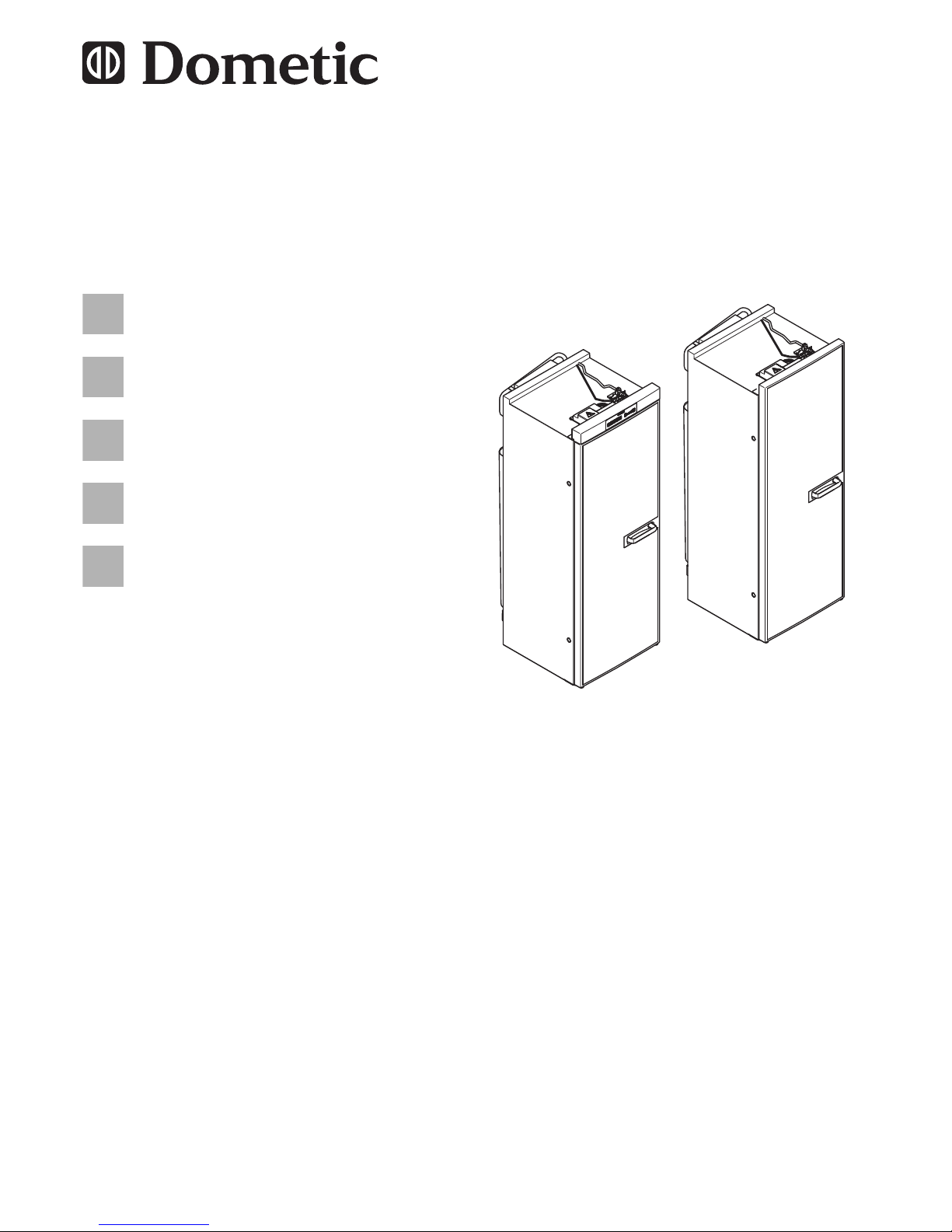
586,5 mm420 mm
1293 mm
RML 9330, RML 9331, RML 9335
553 mm
468 mm
1293 mm
RML 9430, RML 9431, RML 9435
2
Page 3
RML9330 – RML9435
3
2
3
4
1
3
≥ 1050
< 1050
1
4
Page 4
RML9330 – RML9435
4
20 – 40
> 40
> 40
5
≥ 1350
20 – 40
1
6
Page 5
RML9330 – RML9435
5
≥ 300
1 2
7
918
1
2
3
4
1
3
2
4
LS 230 LS 330
0
Page 6
RML9330 – RML9435
6
LS 230
LS 330
a
LS 230
LS 330
b
LS 230
LS 330
1.
2.
3.
c
1
2
d
Page 7

RML9330 – RML9435
7
1.
2.
e
f
1
2
3
4
g
1
2
h
1.
2.
3.
RML 9430
i
1.
3.
2.
RML 9431, RML 9435
j
Page 8
RML9330 – RML9435
8
k
1.
2.
l
2x
n2xm
p
o
q
Page 9
RML9330 – RML9435
9
448
194,5
1216
46
≤ 2,5
≤ 2,5
≤ 2,5
402
189
1270,5
49583,5
402
189
1270,5
49583,5
AB
r
1.
3.
2.
A B
s
SW 17
SW 14
t
Page 10
RML9330 – RML9435
10
bl br ge gn rt sw ws
EN Blue Brown Yellow Green Red Black White
ES Azul Marrón Amarillo Verde Rojo Negro Blanco
IT Blu Marrone Giallo Verde Rosso Nero Bianco
PT Azul Castanho Amarelo Verde Vermelho Preto Branco
EL Μπλε Μπλε Κίτρινος Πράσινος Κόκκινος Μαύρος Άσπρος
15
14
3
6
78
1
2
4
5
12
11
9
10
10
N
L
G
ge/gn
ge/gn
V85
bl
1a
1b
3a
3b
5a
5b
2b
2a
4b
4a
6b
6a
87
85 86
30
br
ws
sw
bl
rt
br
br
bl
rt
rt
ge/gn
br
br
bl
bl bl
br
br
ws
ws
br
br
ge
gn
ws
ws
ws
ws
sw
sw
br
br
br br
gn
ge
ge
+
+
_
+
_
F
E
13
10
u
Page 11
RML9330 – RML9435
11
br rt sw ws
EN Brown Red Black White
ES Marrón Rojo Negro Blanco
IT Marrone Rosso Nero Bianco
PT Castanho Vermelho Preto Branco
EL Μπλε Κόκκινος Μαύρος Άσπρος
IN OUT
LLNN
AC
TO GV 12VDCOUT
TO FC
TOP
CE-0085XXXXXX
241 0241-
Typ: P-860
ABS
HE OUT 12 VDC HE IN
sw
sw
rt
brbrbrws
S+D+(+)
(+)
(-)
(-)
(+)
(-)
rt
rt
L
NL
A
BCDE FG
1
2
6
5
4
8
7
9
10
3
12
13
11
N
14
15
v
Page 12
RML9330 – RML9435
12
RML 93…
RML 94…
w
Page 13

EN
RML9330 – RML9435
13
Please read this instruction manual carefully before installation and
first use, and store it in a safe place. If you pass on the product to
another person, hand over this instruction manual along with it.
I
Table of contents
1 Explanation of symbols . . . . . . . . . . . . . . . . . . . . . . . . . . . . . . . . . . 14
2 Safety instructions . . . . . . . . . . . . . . . . . . . . . . . . . . . . . . . . . . . . . . 14
3 Scope of delivery . . . . . . . . . . . . . . . . . . . . . . . . . . . . . . . . . . . . . . . 16
4 Accessories . . . . . . . . . . . . . . . . . . . . . . . . . . . . . . . . . . . . . . . . . . . 16
5 Intended use . . . . . . . . . . . . . . . . . . . . . . . . . . . . . . . . . . . . . . . . . . 17
6 Installing the refrigerator . . . . . . . . . . . . . . . . . . . . . . . . . . . . . . . . . 17
7 Connecting the refrigerator . . . . . . . . . . . . . . . . . . . . . . . . . . . . . . . 23
8 Technical data . . . . . . . . . . . . . . . . . . . . . . . . . . . . . . . . . . . . . . . . . 29
NOTE
You can find details on the operation in the manual.
Page 14

EN
Explanation of symbols RML9330 – RML9435
14
1 Explanation of symbols
!
!
A
I
2 Safety instructions
The manufacturer accepts no liability for damage in the following cases:
Faulty assembly or connection
Damage to the product resulting from mechanical influences and excess
voltage
Alterations to the product without express permission from the manu-
facturer
Use for purposes other than those described in the operating manual
!
WARNING!
Never open the absorber unit. It is under high pressure and can
cause injury if it is opened.
Ensure clean and residue-free handling if silicon sealant or
similar is used. There is a risk of fire if silicone filaments come
into contact with hot parts or naked flames.
Do not operate the refrigerator if it is visibly damaged.
If the AC power cable for this refrigerator is damaged, it must be
replaced by the manufacturer, customer service or a similarly
qualified person in order to prevent safety hazards.
WARNING!
Safety instruction: Failure to observe this instruction can cause
fatal or serious injury.
CAUTION!
Safety instruction: Failure to observe this instruction can lead to
injury.
NOTICE!
Failure to observe this instruction can cause material damage and
impair the function of the product.
NOTE
Supplementary information for operating the product.
Page 15

EN
RML9330 – RML9435 Safety instructions
15
Never use a naked flame to check the refrigerator for leaks.
This refrigerator may only be repaired by qualified personnel.
Inadequate repairs may cause serious hazards.
Only use propane or butane gas (not natural gas).
Only operate the refrigerator at the pressure shown on the type
plate. Use a DIN-DVGW-approved pressure regulator with a
fixed setting in accordance with DIN EN 12864.
Dismantle all refrigerator doors for the disposal of the old
refrigerator and leave the shelves in the refrigerator to prevent
accidental enclosure and suffocation.
!
CAUTION!
Danger of crushing! Do not put your fingers into the hinge.
Before starting the device, ensure that the power supply line
and the plug are dry.
A
NOTICE!
Only hold the refrigerator at the body of the refrigerator during
transport. Never hold the refrigerator at the absorber unit, the
cooling fins, the gas pipes, the door or the control panel.
Make sure that the refrigerator circuit is not damaged during
transportation. The refrigerant in the refrigerator circuit is highly
flammable.
In the event of any damage to the refrigerator circuit:
– Avoid naked flames and sparks.
– Air the room well.
Do not install the refrigerator near naked flames or other heat
sources (heaters, direct sunlight, gas ovens etc.).
Danger of overheating!
Always ensure sufficient ventilation so that the heat generated
during operation can dissipate. Make sure that the refrigerator
is sufficiently far away from walls and other objects so that the
air can circulate.
Check that the voltage specification on the type plate is the
same as that of the power supply.
Do not open the refrigerant circuit under any circumstances.
Only use the AC connection cable supplied to connect the
refrigerator to the AC mains.
Only use cables with a suitable size.
Page 16
EN
Scope of delivery RML9330 – RML9435
16
Never pull the plug out of the socket by the connection cable.
The refrigerator may not be exposed to rain.
3 Scope of delivery
Refrigerator
Ice-cube tray
Operating manual
Installation manual
4 Accessories
Available as accessories (not included in the scope of delivery):
All the accessories are available from specialist dealers. If you have any
questions, please contact the dealer or your service partner directly.
Description
Fan kit for boosting the cooling capacity at high ambient temperatures
Ventilation grille
Winter cover for the ventilation grille
Divider, bottle finger (RML9430/9431/9435 only)
Shelf with safety edges (RML9430/9431/9435 only)
Breakfast tray (RML9430/9431/9435 only)
Vario shelves (door shelves can be fitted in any position)
Door shelf locking
Bottle holder for door shelf locking
Shelf locking
Page 17

EN
RML9330 – RML9435 Intended use
17
5 Intended use
The RML9330, RML9331, RML9335, RML9430, RML9431 and RML9435
refrigerators are designed for installation in caravans or motorhomes. They
are only suitable for cooling and storing foodstuffs. The refrigerators are not
intended for the proper storage of medicine.
The refrigerators are designed to be operated on a DC power supply and an
AC socket and can be independently powered by liquid gas (propane or
butane). The refrigerators may not be run on natural gas or city gas.
6 Installing the refrigerator
6.1 Preparing the installation
When installing the refrigerator, note the following:
To enable the refrigerant to circulate properly, the refrigerator may not
exceed an angle of 3 °.
To do this, park the vehicle on a level surface and check to see if the
ice-cube tray is flat in the refrigerator.
The refrigerator must be installed so that it is easily accessible for service
work, easy to de-install and install and can be easily removed from the
vehicle.
The distance between the refrigerator and the rear wall must be at least
20 mm.
The refrigerator must be installed in a recess so that it stands firm when
the vehicle is in motion. Note the following dimensions here (H x W x D in
mm):
– RML9330/9331/9335: 1293 x 420 x 586.5 (fig. 1, page 2)
– RML9430/9431/9435: 1293 x 468 x 553 (fig. 2, page 2)
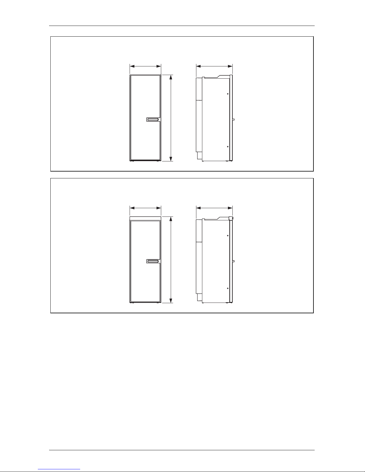
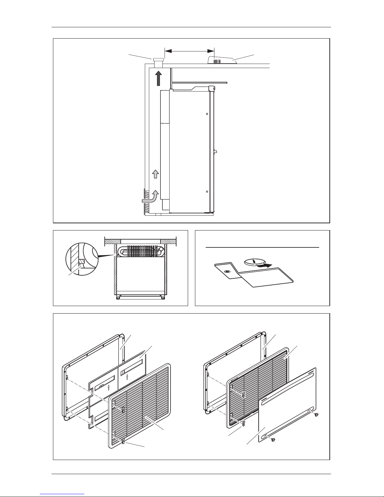
The outer wall must be fitted with an air inlet vent (fig. 3 1, page 3) and
an outlet vent (fig. 3 2, page 3) with ventilation grilles so that the heat
generated can be easily released to the outside:
– Air inlet vent: Fit the ventilation grille as flush as possible to the floor of
the installation niche with a minimum cross-section of 500 cm².
– Outlet vent: fit as far above the refrigerator as possible.
– The distance between the air inlet and outlet vents must be at least
1050 mm (fig. 4, page 3).
Fit a heat conduction plate (fig. 3 3, page 3) above the refrigerator so
that the heat does not accumulate in the vehicle.
Page 18

EN
Installing the refrigerator RML9330 – RML9435
18
If the ventilation grille of the air inlet vent cannot be installed flush to the
ground, an additional inlet vent (fig. 3 4, page 3) must be provided in the
floor for releasing leaked gas.
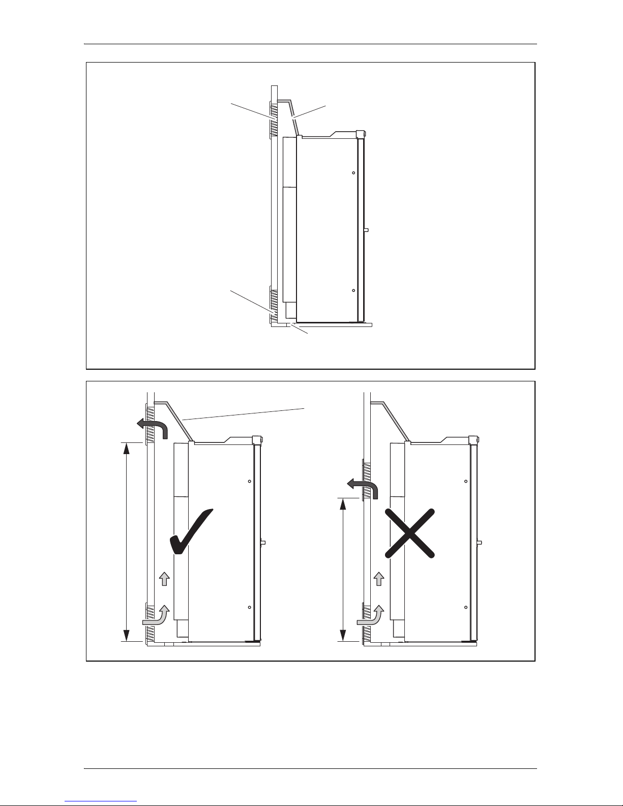
A distance of more than 40 mm between the refrigerator and rear wall
leads to poor performance and increases the power consumption of the
refrigerator. Reduce the space behind the refrigerator to create adequate
air inlet and outlet ventilation (fig. 5, page 4). Use a ventilation plate, for
example, to do this.
If the minimum distance between the air inlet and outlet vents cannot be
met, a roof vent must be installed instead of the air outlet vent.
– The roof vent should be installed directly above the back of the
refrigerator as far as this is possible. Use an air duct (fig. 6 1, page 4)
if you need to install the roof vent offset, otherwise heat will accumu-
late there.
– The distance between the air inlet vent and the roof vent must be at
least 1350 mm (fig. 6, page 4).
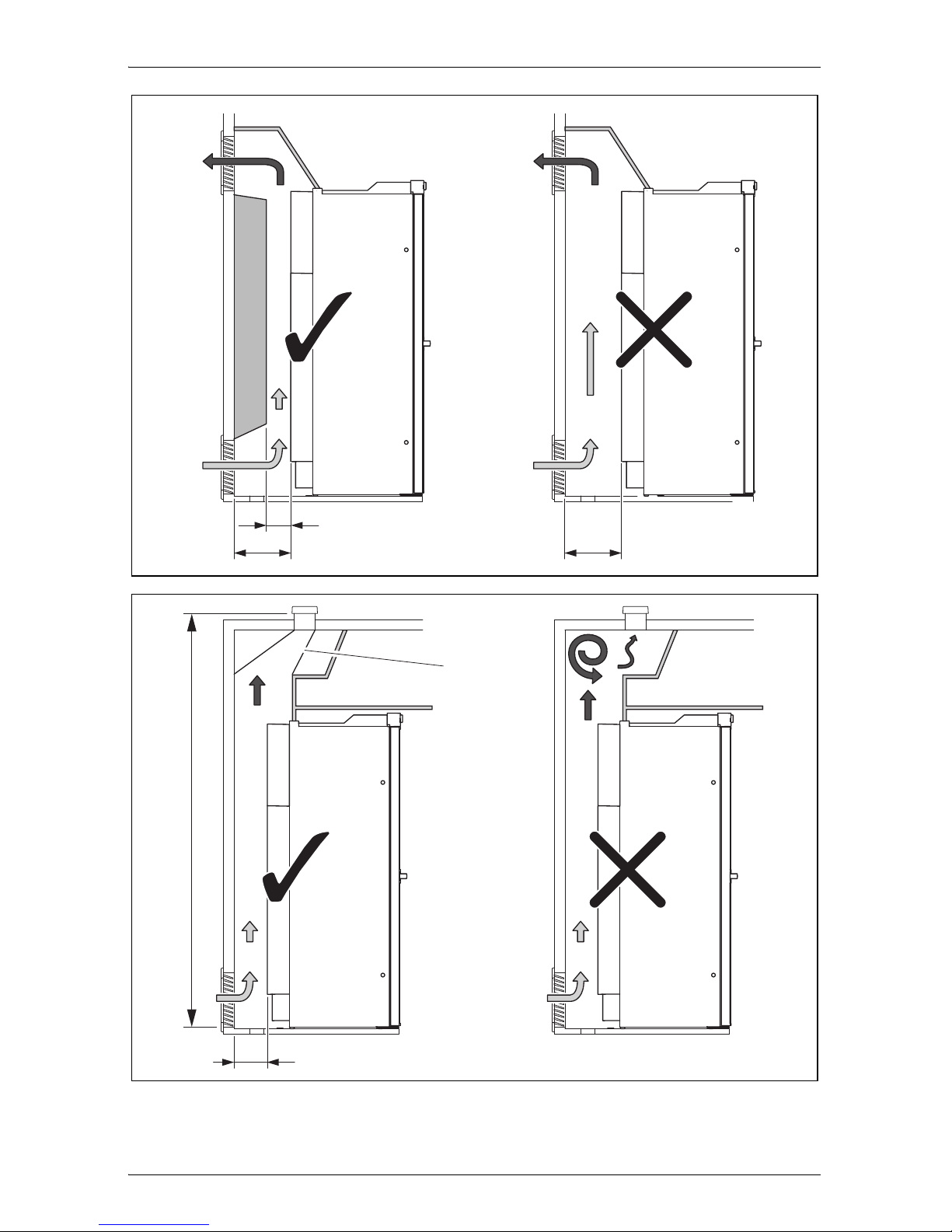
– If a roof air conditioner is provided, the distance between the roof vent
(fig. 7 1, page 5) and the air outlet of the roof air conditioner
(fig. 7 2, page 5) must be at least 300 mm.
The refrigerator must not be installed at the side of the air inlet and outlet
vents as this leads to poor performance and increases the power
consumption of the refrigerator.
The air inlet and outlet vents must not be covered by vehicle parts (such
as an open door or by installing accessories such as bicycle racks) while
operating.
Install a fan kit for distances of 25 mm – 45 mm between the rear wall of
the refrigerator and air outlet vent (see chapter “Accessories” on
page 16).
Install the refrigerator so that it is protected from excessive heat, as this
leads to poor performance and increases the power consumption of the
refrigerator.
The electrical installation must comply with national and local regulations.
European standards: EN 60335-1, EN 60335-2-24, EN 1648-1 and
EN 1648-2.
The gas installation must comply with national and local regulations.
European standard: EN 1949.
The refrigerator must be installed in a draught-proof location in
accordance with EN 1949, see chapter “Installing the refrigerator in a
draught-proof location” on page 19.
Page 19

EN
RML9330 – RML9435 Installing the refrigerator
19
6.2 Installing the refrigerator in a draught-proof
location
Gas-powered refrigerators in caravans or motorhomes must be installed in a
draught-free location according to EN 1949. This means that the combustion
air is not extracted from the interior and the exhaust fumes are prevented
from directly entering the living space.
A suitable seal must be fitted between the rear panel of the refrigerator and
the interior of the vehicle.
!
The manufacturer recommends using a flexible seal to ease removal and
installation for maintenance purposes.
➤ Attach the sealing lips (fig. 8 1, page 5) to a stop rail behind the
refrigerator, for example, by using an adhesive.
➤ When installing, push the refrigerator against the stop rails with the
sealing lips. This then seals the space behind the refrigerator to the
interior of the vehicle.
6.3 Making air inlet and outlet vents
I
➤ Make an air inlet vent and an air outlet vent in the outer wall with the
size of 410 mm x 249 mm. When doing so, observe the information, see
chapter “Preparing the installation” on page 17.
If the ventilation grille of the air inlet vent cannot be installed flush with the
floor of the niche, you need to install an inlet vent in the floor:
➤ Make an air inlet vent in the floor (fig. 3 4, page 3) behind the refrigerator
near the gas burner.
➤ Shield the end of the opening with a deflector to prevent sludge or dirt
from getting inside while driving (fig. 9, page 5).
WARNING! Fire hazard!
Do not use flammable materials such as silicone sealants, foam
or similar for the draught-proof installation.
NOTE
At high ambient temperatures, the refrigerator can only provide its
maximum cooling capacity if the optimum ventilation has been
provided.
Page 20
EN
Installing the refrigerator RML9330 – RML9435
20
If you have to use a roof vent instead of the air outlet vent:
➤ Cut out a section in the roof. Refer to the roof vent instruction manual for
the required dimensions. When doing so, observe the information, see
chapter “Preparing the installation” on page 17.
6.4 Installing the ventilation grille
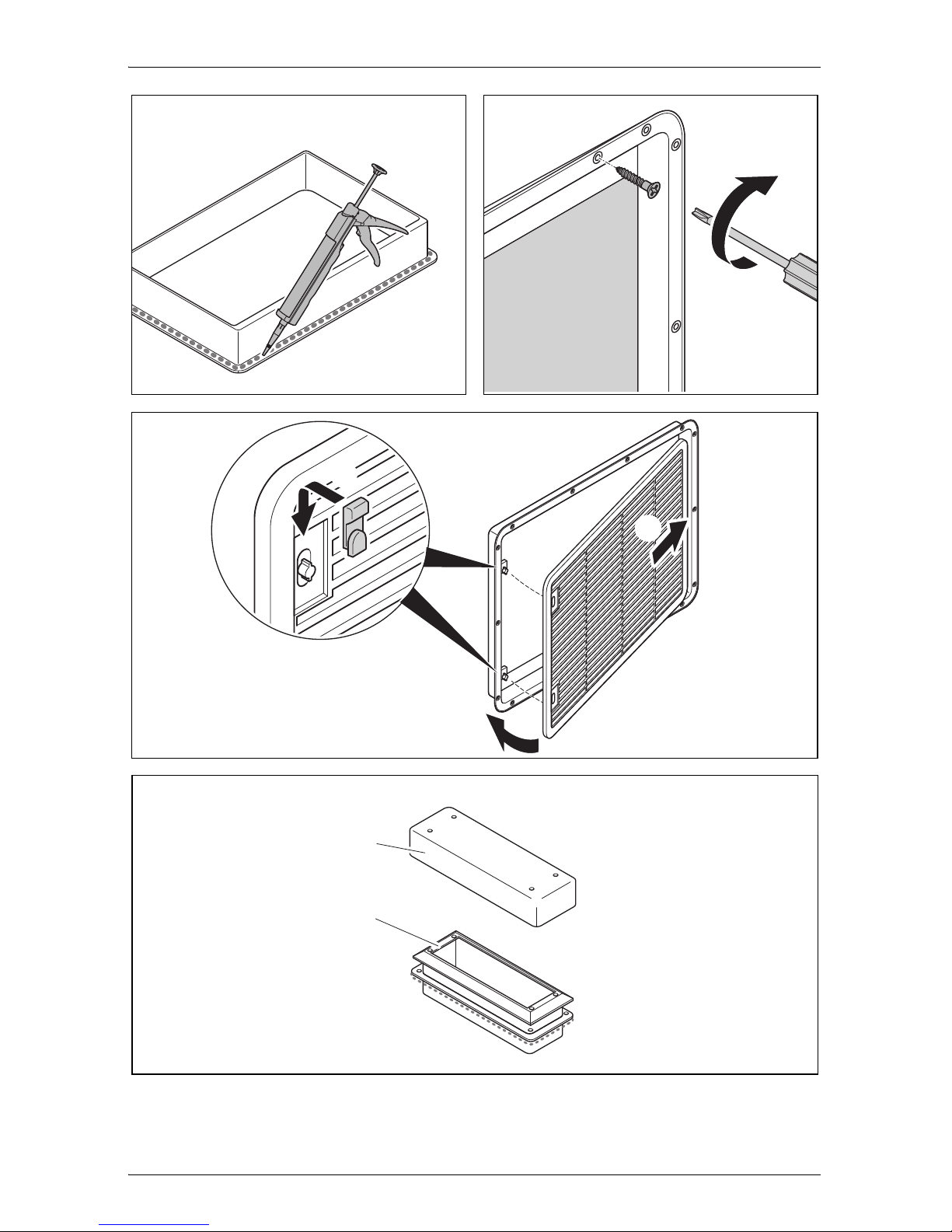
➤ Ensure the installation frame is water resistant (fig. a, page 6).
➤ Insert the installation frame and screw it down tightly (fig. b, page 6).
➤ Fit the ventilation grille (fig. c, page 6).
➤ Insert the slider and lock the ventilation grille with it (fig. c, page 6).
6.5 Install the roof vent
➤ Ensure the installation frame is water resistant (fig. e, page 7).
➤ Insert the installation frame and screw it down tightly (fig. e, page 7).
➤ Insert the hood and screw it down tightly (fig. f, page 7).
No. in
fig. 0, page 5
Description
1 Installation frame
2 Ventilation grille
3 Winter cover
4 Slider
No. in
fig. d, page 6
Description
1 Installation frame
2Hood
Page 21

EN
RML9330 – RML9435 Installing the refrigerator
21
6.6 Install the flue duct
I
The flue duct is installed at the factory. Follow these steps when you have
removed the flue duct and want to reinstall it (fig. g, page 7):
➤ Place the T-piece (1) on the adaptor (2) and the flue pipe (3).
➤ Direct the T-piece at an angle of 45° towards the rear wall.
➤ Attach the T-piece, adaptor and flue pipe with a screw (4).
6.7 Securing the refrigerator
!
I
Proceed as follows (fig. h, page 7):
➤ Move the refrigerator into its final location.
➤ Fasten the four screws (1) through the four plastic washers in the sides of
the refrigerator, and further into the wall.
➤ Put the caps (2) onto the screw heads.
6.8 Reversing the door (RML9430/9431/9435 only)
➤ Remove the control panel.
– RML9430: Unscrew the dials carefully and loosen the screws, fig. i,
page 7
– RML9431/9435: Open the refrigerator door and undo the screws
underneath the control panel, fig. j, page 7
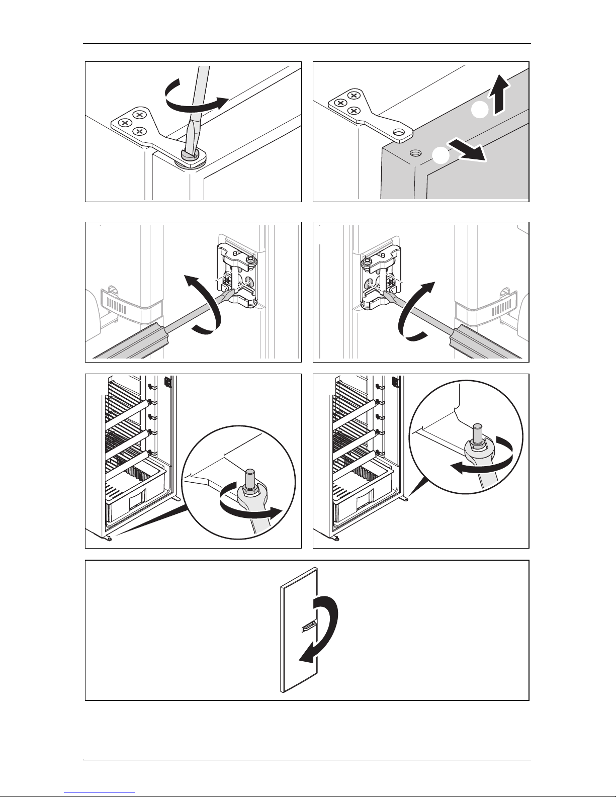
➤ Undo the hinge screw on the top door hinge and keep it in a safe place
(fig. k, page 8).
NOTE
Do not install an additional flue stack, as this leads to poor
performance and increases the power consumption of the
refrigerator.
CAUTION!
Only drill through the receptacles provided, otherwise foamed
components, including cables, can be damaged.
NOTE
Attach the side walls or the attached strips so that the screws are
tight, even when under increased loads (while driving).
Page 22

EN
Installing the refrigerator RML9330 – RML9435
22
➤ Lift up the door and remove it (fig. l, page 8).
➤ Undo the two screws on the door lock and remove the door lock (fig. m,
page 8).
➤ Place the door lock on the other side again and tighten it with the two
screws (fig. n, page 8).
➤ Undo the hinge pin (fig. o, page 8) and position it on the other side
(fig. p, page 8).
➤ Turn the door by 180° (fig. q, page 8).
➤ Place the door on the hinge pin.
➤ Replace the control panel and screw it down tightly.
6.9 Put on the door panel
A
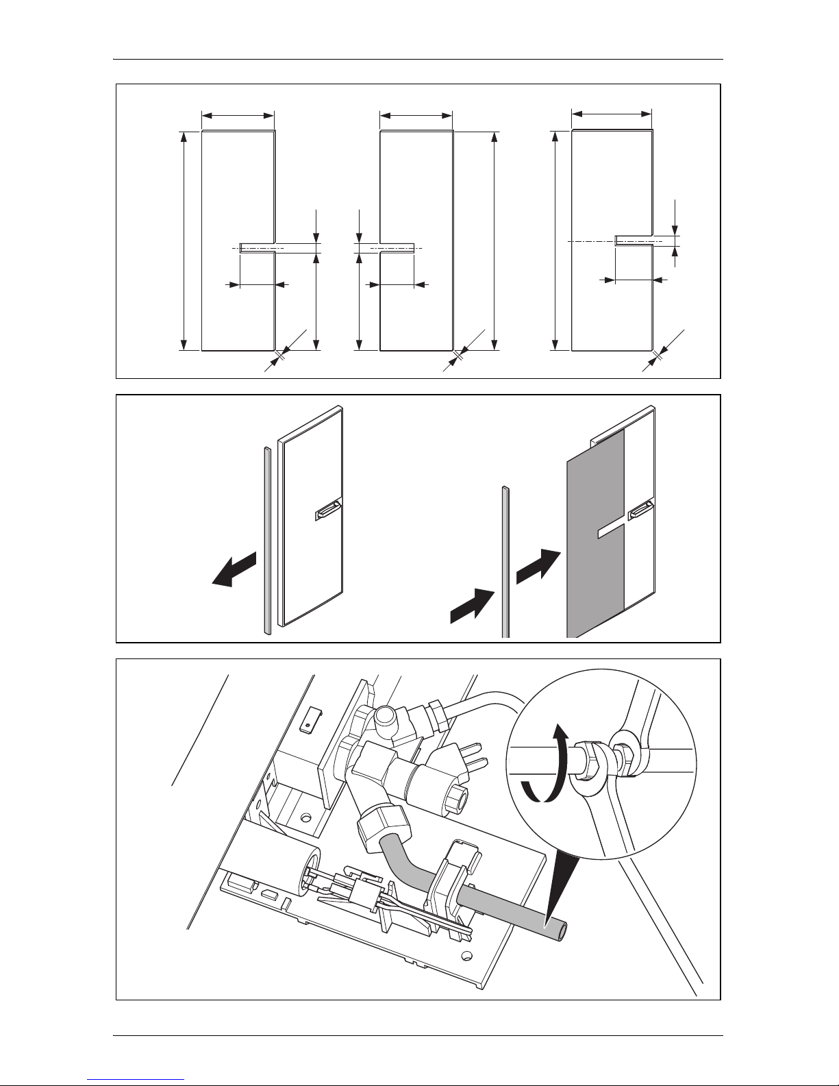
The door panel has the following dimensions (fig. r, page 9):
RML9330/9331/9335: A
RML9430/9431/9435: B
Proceed as follows (fig. s, page 9):
➤ Remove the door trim carefully. It is only stuck on and held by small
hooks (A).
➤ Slide the new panel into the opening (B).
➤ Replace the door trim (B).
✓ The door trim is secure once it clicks into place.
If you have laid the refrigerator on its side to insert the panel:
➤ Wait a few minutes before you switch on the refrigerator.
NOTICE! Beware of damage
Only ever lay the refrigerator on its side and never on its back.
Otherwise the unit may be damaged.
Page 23

EN
RML9330 – RML9435 Connecting the refrigerator
23
7 Connecting the refrigerator
7.1 Connecting to the gas supply
A
I
It must be possible to shut off the refrigerator from the gas line separately by
means of a shut-off device. The shut-off device must be easily accessible.
➤ Connect the refrigerator securely by hand to the gas supply (fig. t,
page 9).
The following applies for Europe: Use a cutting ring fitting in accordance
with EN 1949.
A hose connection is not permitted.
➤ Have a leak test and a flame test performed in accordance with EN 1949
by an authorised specialist.
Ensure you are issued with a certificate of inspection.
NOTICE!
This refrigerator may only be connected to the gas supply by
a specialist in accordance with the applicable guidelines and
standards.
Only use cylinders of propane or butane gas (not natural gas
or city gas) with an approved pressure reduction valve and
suitable head. Compare the pressure information on the type
plate with the pressure information on the pressure regulator
on the propane or butane gas cylinder.
Only operate the refrigerator at the pressure shown on the
type plate.
Please note the pressures which are permitted in your country.
Use a DIN-DVGW-approved pressure regulator with a fixed
setting:
– The following applies for Germany: DIN EN 12864
– The following applies for Europe: EN 732 and EN 1949
NOTE
The refrigerator is equipped for a connection pressure of 30 mbar.
Use a 50/30 mbar pressure regulator when connected to a
50 mbar system.
Page 24

EN
Connecting the refrigerator RML9330 – RML9435
24
7.2 Connecting to 12 Vg and 230 Vw
A
I
NOTICE!
The electrical installation and repairs may only be performed
by a specialist in accordance with the applicable regulations
and standards.
According to EN 1648-1, the respective negative and positive
cables of the DC connections for heating and lighting may not
be joined with one another in a caravan. This can cause
electrical interference or damage to electrical components.
The inverter may only be connected by a specialist.
NOTE
The mains socket must be easily accessible so that you can
unplug the power cord if required, thereby disconnecting the
refrigerator from the power.
The plug of the AC connection cable must not be cut off.
The connection cables must be laid so that they do not come
in contact with hot parts of the unit/burner or with sharp edges.
Changes to the internal electrical installation or the connection
of other electrical components (e.g. extra third party fans) to
the internal wiring of the refrigerator will void the E1/CE
approval and any claims from the guarantee and product
liability.
Page 25
EN
RML9330 – RML9435 Connecting the refrigerator
25
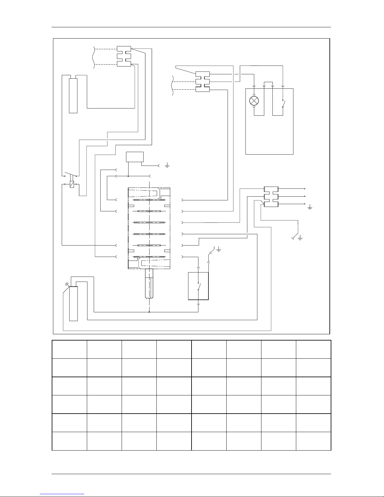
➤ Connect the RML 9330/9430 refrigerators as follows (fig. u, page 10).
Item Description
1 Heating element positive terminal (+) DC power
2 Heating element earth terminal DC power
3 Heating cartridge terminal strip DC power
4 Lighting negative terminal (–)
5 Lighting positive terminal (+)
6 Lighting terminal strip DC power
7 LED lighting DC power
8 LED lighting switch
9 AC power connection cable
10 Earth housing (upper section)
11 Thermal power adapter
12 Galvanometer
13 Heating cartridge AC power
14 Relay 30 A
15 Heating cartridge DC power
Page 26
EN
Connecting the refrigerator RML9330 – RML9435
26
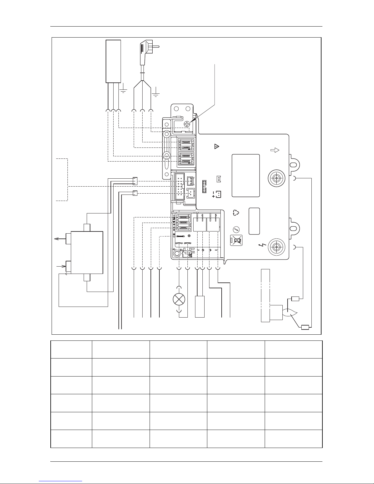
➤ Connect the RML9331/9335/9431/9435 refrigerators as follows (fig. v,
page 11):
Item Description
1 Heating cartridge AC power
2 AC power connection cable
3 Earth AC power
4 Ionisation
5 Ignition
6 Burner
7 Heating cartridge DC power supply
8 Heating cartridge DC power
9 LED lighting
10 Electronics DC power supply
11 Gas inlet
12 Gas outlet
13 Gas valve
14 DC power outlet
15 Gas valve supply line
A Optional connections to DC power outlet
B Negative terminal (–) DC permanent supply for electronics
C Positive terminal (+) DC permanent supply for electronics
D Connection D+
E Connection S+
F Heating element positive terminal (+) DC power
G Heating element earth terminal DC power
Page 27

EN
RML9330 – RML9435 Connecting the refrigerator
27
AC power:
➤ Connect the refrigerator with the mains plug to an AC socket.
DC power:
Please note the following cable sizes:
– < 6 m (interior): 6 mm
2
– > 6 m (interior): 10 mm
2
– Connections D+ and S+: 1 mm
2
– Cable fed via drawbar (caravans only): 2.5 mm
2
➤ Secure the power supply line to the heating element (connection 4) with
a 20 A fuse and the supply for lighting/electronics (connection 6) with a
2 A fuse.
➤ Connect the heating element (connections 3 and 4) with the shortest
possible cable.
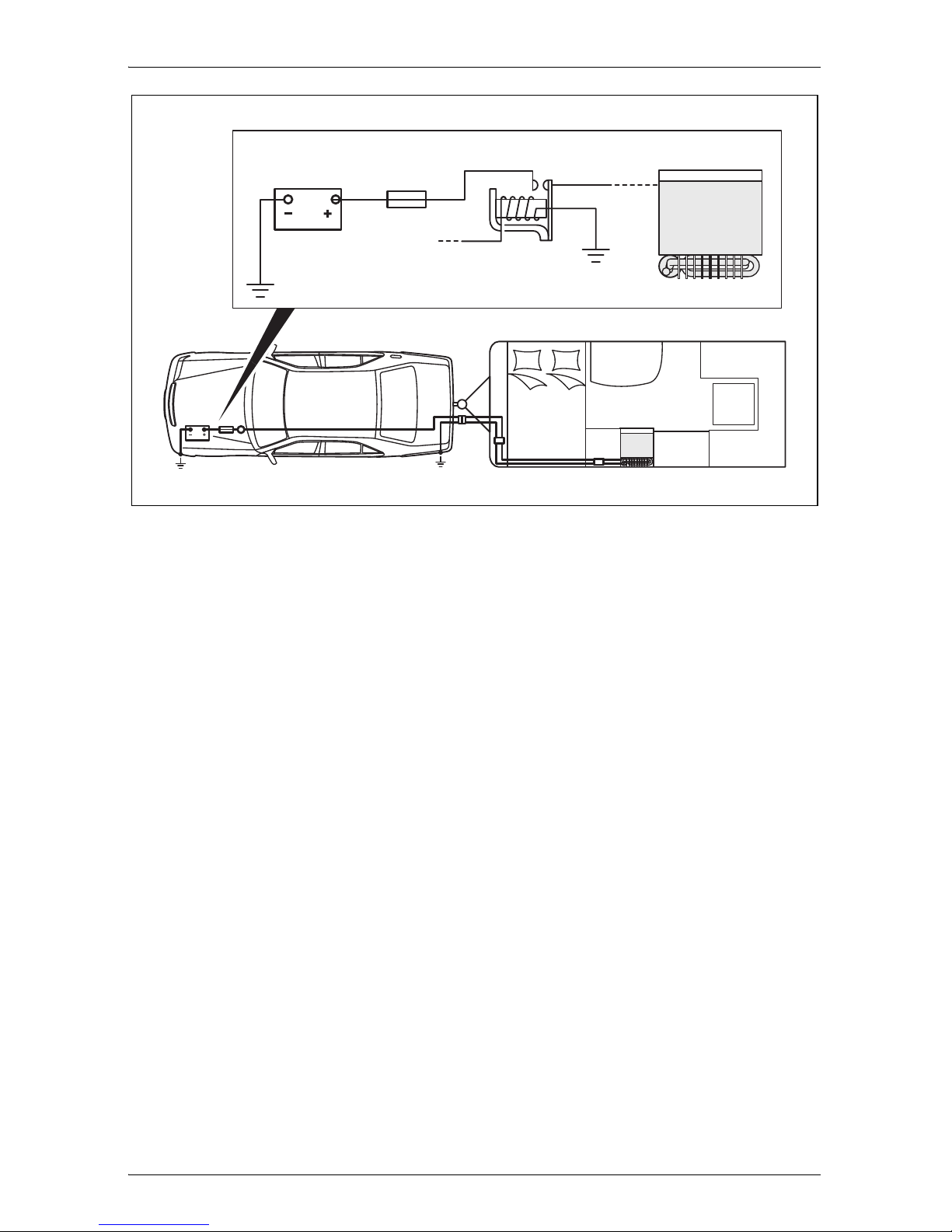
➤ Run the cable to the heating element (connections 3 and 4) via a relay
controlled by an ignition socket to prevent the battery from completely
discharging if the engine is switched off accidentally (fig. w, page 12).
➤ RML9331/9335/9431/9435 only: Connect a 12 V continuous supply to
the connection for lighting/electronics (terminals 5 and 6).
D+ (RML9335/9435 only)
In automatic mode, the refrigerator selects the most favourable mode
available. The refrigerator is only operated with direct current when the
vehicle engine is running. The electronics of the refrigerator uses the
signal D+ from the light system to detect the running engine.
➤ Connect the D+ connection to the controls (fig. v D, page 11) with the
respective terminal of the vehicle.
Page 28

EN
Connecting the refrigerator RML9330 – RML9435
28
S+ (RML9335/9435 only)
In automatic mode, the refrigerator is first powered with DC power from the
vehicle's own solar system. The refrigerator electronics uses the S+ signal
of the solar charge controller to detect a solar system. The solar charge
controller must have an AES output.
➤ Connect the S+ connection on the controller (fig. w E, page 12) to the
respective terminal of the solar charge controller.
Suitable solar charge controllers are available from specialist dealers.
The manufacturer recommends, for example:
Büttner MT 300-S
(www.buettner-elektronik.de)
Votronic MPP 240 Duo Digital
(www.votronic.de)
Page 29
EN
RML9330 – RML9435 Technical data
29
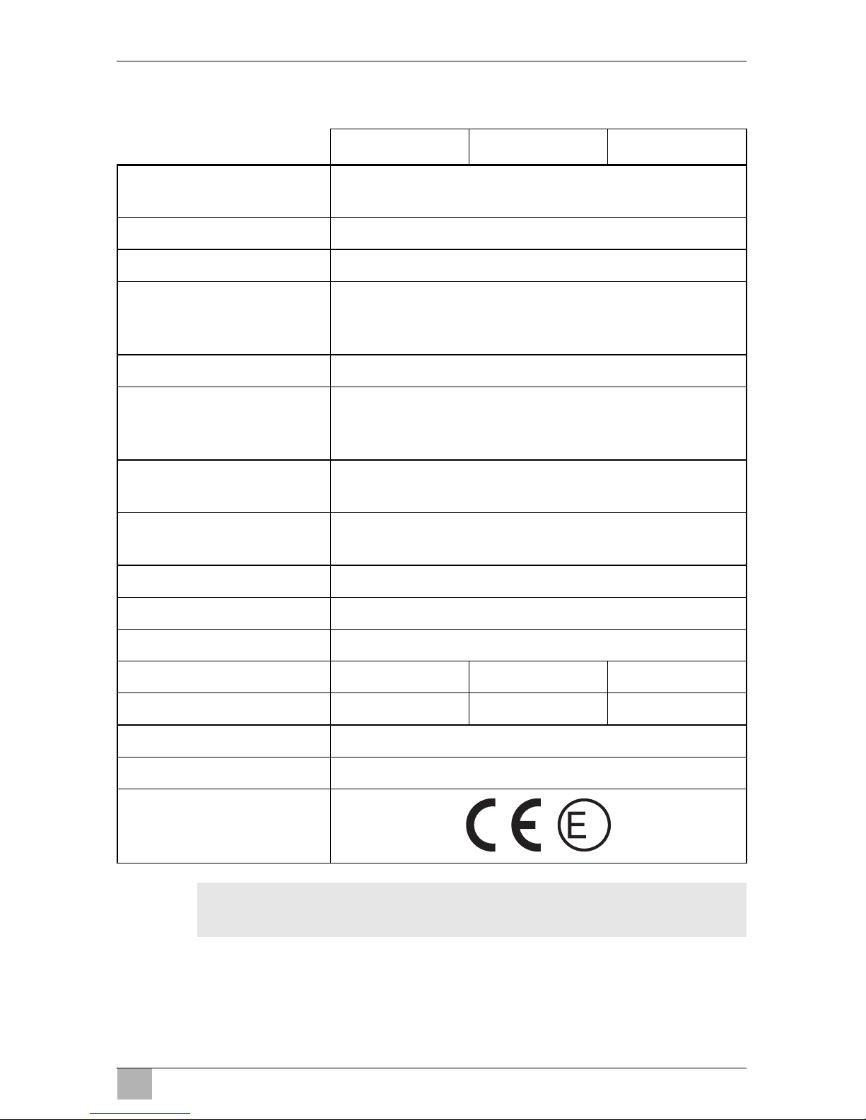
8 Technical data
I
RML9330 RML9331 RML9335
Voltage: 230 Vw / 50 Hz
12 Vg
Gross capacity: 134 l
Ice compartment: 12 l
Gross capacity
(excluding ice
compartment):
138.5 l
Net capacity: 129 l
Net capacity
(excluding ice
compartment):
133.5 l
Power consumption: 170 W (230 Vw)
170W (12Vg)
Power consumption: 3.2 kWh/24 h (230 Vw)
340 Ah/24 h (12 Vg)
Gas consumption: 380 g/24 h
Climatic class: SN
Noise emission: 0 dB(A)
Ignition: Manual Automatic Automatic
Power choice: Manual Manual Automatic
Dimensions: fig. 1, page 2
Weight: 37 kg
Inspection/certification:
NOTE
You can obtain the CE declaration of conformity at Dometic.
1
Page 30
EN
Technical data RML9330 – RML9435
30
I
RML9430 RML9431 RML9435
Voltage: 230 Vw / 50 Hz
12 Vg
Gross capacity: 146 l
Ice compartment: 12 l
Gross capacity
(excluding ice
compartment):
151 l
Net capacity: 142 l
Net capacity
(excluding ice
compartment):
148 l
Power consumption: 170 W (230 Vw)
170W (12Vg)
Power consumption: 3.2 kWh/24 h (230 Vw)
340 Ah/24 h (12 Vg)
Gas consumption: 380 g/24 h
Climatic class: SN
Noise emission: 0 dB(A)
Ignition: Manual Automatic Automatic
Power choice: Manual Manual Automatic
Dimensions: fig. 2, page 2
Weight: 37 kg
Inspection/certification:
NOTE
You can obtain the CE declaration of conformity at Dometic.
1
Page 31

ES
RML9330 – RML9435
31
Lea detenidamente estas instrucciones antes de llevar a cabo la instalación y puesta en funcionamiento, y consérvelas en un lugar seguro.
En caso de vender o entregar el producto a otra persona, entregue
también estas instrucciones.
I
Índice
1 Explicación de los símbolos. . . . . . . . . . . . . . . . . . . . . . . . . . . . . . . 32
2 Indicaciones de seguridad . . . . . . . . . . . . . . . . . . . . . . . . . . . . . . . . 32
3 Volumen de entrega. . . . . . . . . . . . . . . . . . . . . . . . . . . . . . . . . . . . . 34
4 Accesorios . . . . . . . . . . . . . . . . . . . . . . . . . . . . . . . . . . . . . . . . . . . . 35
5 Uso adecuado . . . . . . . . . . . . . . . . . . . . . . . . . . . . . . . . . . . . . . . . . 35
6 Montaje de la nevera . . . . . . . . . . . . . . . . . . . . . . . . . . . . . . . . . . . . 36
7 Conexión de la nevera . . . . . . . . . . . . . . . . . . . . . . . . . . . . . . . . . . . 44
8 Datos técnicos . . . . . . . . . . . . . . . . . . . . . . . . . . . . . . . . . . . . . . . . . 50
NOTA
Las indicaciones de uso se encuentran en las instrucciones de
uso.
Page 32

ES
Explicación de los símbolos RML9330 – RML9435
32
1 Explicación de los símbolos
!
!
A
I
2 Indicaciones de seguridad
El fabricante declina toda responsabilidad ante daños ocurridos en los
siguientes casos:
errores de montaje o de conexión
daños en el producto debido a influencias mecánicas y sobretensiones
modificaciones realizadas en el producto sin el expreso consentimiento
del fabricante
utilización del aparato para fines distintos a los descritos en las
instrucciones
!
¡ADVERTENCIA!
No abra nunca el grupo absorbedor. Está bajo alta presión y
puede causar lesiones si se abre.
Asegúrese de trabajar de forma segura y limpia cuando se
emplea pasta para juntas de silicona o similares. Si hilos de
silicona entran en contacto con piezas calientes o fuego abierto,
existe peligro de incendio.
No ponga la nevera en funcionamiento si presenta desperfectos
visibles.
¡ADVERTENCIA!
Indicación de seguridad: su incumplimiento puede acarrear la
muerte o graves lesiones.
¡ATENCIÓN!
Indicación de seguridad: su incumplimiento puede acarrear
lesiones.
¡AVISO!
Su incumplimiento puede acarrear daños materiales y perjudicar
el correcto funcionamiento del producto.
NOTA
Información adicional para el manejo del producto.
Page 33

ES
RML9330 – RML9435 Indicaciones de seguridad
33
Si se daña el cable de conexión de corriente alterna de esta
nevera, el fabricante, su servicio de atención al cliente o una
persona cualificada debe reemplazarlo para evitar así posibles
peligros.
No compruebe nunca la hermeticidad de la nevera con fuego
abierto.
Solo personal especializado está autorizado a realizar repara-
ciones en la nevera. Una reparación incorrecta entraña riesgos
considerables.
Utilice solo gas propano o butano (no gas natural).
Solo está permitido usar la nevera con la presión indicada en la
placa de características. Utilice un presostato fijo homologado
DIN-DVGW de conformidad con DIN EN 12864.
Desmonte las puertas de la nevera al desechar la nevera usada
y deje las repisas en la nevera para evitar un cierre involuntario
y la asfixia.
!
¡ATENCIÓN!
¡Peligro de aplastamiento! No introduzca la mano en el área de
acción de la bisagra.
Antes de la puesta en funcionamiento, asegúrese de que el
cable de alimentación y la clavija de enchufe estén secos.
A
¡AVISO!
Durante el transporte, sujete la nevera solo por su cuerpo. No
sujete nunca la nevera por el grupo absorbedor, las aletas de
refrigeración, los conductos de gas, la puerta o el panel de
mando.
Al transportarla, asegúrese de no dañar el circuito de refrigera-
ción. El refrigerante del circuito de refrigeración es muy inflamable.
En caso de daños en el circuito de refrigeración:
– evite las llamas abiertas y las chispas.
– Ventile bien la habitación.
No monte la nevera cerca de fuego abierto ni de otras fuentes
de calor (calefacción, estufas de gas, etc.).
Page 34

ES
Volumen de entrega RML9330 – RML9435
34
¡Peligro de sobrecalentamiento!
Asegúrese de que quede garantizada en todo momento una
evacuación adecuada del calor que se genera durante el funcionamiento. Asegúrese también de que la nevera guarde la
suficiente distancia respecto a paredes u objetos, de forma que
el aire pueda circular.
Compare el valor de tensión indicado en la placa de caracterís-
ticas con el suministro de energía existente.
No abra nunca el circuito de refrigeración.
Conecte la nevera a la red de corriente alterna solo con el cable
de conexión de corriente alterna correspondiente.
Utilice únicamente cables que tengan la sección adecuada.
No desenchufe nunca el cable de conexión tirando de él.
La nevera no debe quedar expuesta a la lluvia.
3 Volumen de entrega
Nevera
Bandeja para cubitos de hielo
Instrucciones de uso
Instrucciones de montaje
Page 35

ES
RML9330 – RML9435 Accesorios
35
4 Accesorios
Disponibles como accesorios (no incluidos en el volumen de entrega):
Todos los accesorios están disponibles en su distribuidor. Si tiene preguntas, diríjase directamente a su distribuidor o socio de servicio.
5 Uso adecuado
Las neveras RML9330, RML9331, RML9335, RML9430, RML9431 y
RML9435 están diseñadas para su montaje en caravanas o autocaravanas.
Estas neveras son aptas únicamente para enfriar y guardar alimentos. Las
neveras no están previstas para guardar debidamente medicamentos.
Las neveras están diseñadas para su funcionamiento conectadas a una red
de corriente continua y en una caja de enchufe de corriente alterna y pueden
funcionar independientemente de la corriente con gas licuado (propano o
butano). No está permitido hacer funcionar las neveras con gas ciudad o gas
natural.
Denominación
Kit de ventilador para aumentar la potencia de refrigeración a altas temperaturas
exteriores
Rejilla de ventilación
Cubierta de invierno para la rejilla de ventilación
Distribuidor, reposabotellas (solo RML9430/9431/9435)
Rejilla con protección de bordes (solo RML9430/9431/9435)
Cajón para el desayuno (solo RML9430/9431/9435)
Vario Shelves (estantes de la puerta ajustables en todas las posiciones deseadas)
Estante de la puerta encastrable
Portabotellas para estantes de la puerta encastrables
Rejilla encastrable
Page 36

ES
Montaje de la nevera RML9330 – RML9435
36
6 Montaje de la nevera
6.1 Preparación de la instalación
Durante el montaje de la nevera, tenga en cuenta las siguientes
indicaciones:
Para que el refrigerante pueda circular correctamente, el ángulo de
inclinación de la nevera no debe superar los 3°.
Detenga el vehículo horizontalmente y compruebe si la bandeja para
cubitos de hielo está plana en la nevera.
La nevera debe montarse de manera que sea accesible para labores
de servicio, se monte y desmonte con facilidad y se pueda retirar del
vehículo sin gran esfuerzo.
La distancia entre la nevera y la pared trasera debe ser de al menos
20 mm.
La nevera se debe empotrar en un rincón para que no se desplace con
el movimiento del vehículo. Observe para ello las siguientes medidas
(H x A P en mm):
– RML9330/9331/9335: 1293 x 420 x 586,5 (fig. 1, página 2)
– RML9430/9431/9435: 1293 x 468 x 553 (fig. 2, página 2)
En la pared exterior se debe practicar una abertura de ventilación
(fig. 3 1, página 3) y una de desaireación (fig. 3 2, página 3) con
rejillas de ventilación para que así se pueda disipar al exterior el calor
resultante:
– Abertura de ventilación: La rejilla de ventilación debe estar lo más a
ras posible del suelo del rincón de montaje y tener una sección de por
lo menos 500 cm².
– Abertura de desaireación: lo más por encima posible de la nevera.
– La distancia entre la abertura de ventilación y la abertura de desairea-
ción debe ser de al menos 1050 mm (fig. 4, página 3).
Instale una chapa deflectora de calor por encima de la nevera (fig. 3 3,
página 3) para que el calor no se acumule en el vehículo.
Si la rejilla de ventilación de la abertura de ventilación no se pudiera
montar a ras del suelo, se deberá prever una abertura de ventilación
adicional (fig. 3 4, página 3) en el suelo para evacuar el gas que salga.
Una distancia superior a 40 mm entre la nevera y la pared trasera causa
una merma de potencia y un consumo de energía más elevado de la
nevera. Reduzca el hueco detrás de la nevera como corresponde para
establecer una aireación y ventilación suficiente (fig. 5, página 4).
Use para ello, por ejemplo, una chapa deflectora del aire.
Page 37

ES
RML9330 – RML9435 Montaje de la nevera
37
Si la distancia mínima entre la abertura de ventilación y la abertura de
aireación no se puede cumplir, debe montarse en vez de la abertura de
ventilación un ventilador en el techo.
– El extractor de techo debe instalarse lo más directamente posible
encima de la pared trasera de la nevera. Use un canal de aire
(fig. 6 1, página 4) si tiene que instalar el ventilador en el techo
desplazado, ya que de lo contrario se acumula el calor.
– La distancia entre la abertura de ventilación y el ventilador en el techo
debe ser de al menos 1350 mm (fig. 6, página 4).
– Si se dispone de un equipo de aire acondicionado de techo, la
distancia entre el ventilador en el techo (fig. 7 1, página 5) y la salida
de aire del equipo de aire acondicionado de techo (fig. 7 2, página 5)
debe ser de al menos 300 mm.
No está permitido instalar la nevera a los lados de las aberturas de
aireación y ventilación, ya que causaría una merma de potencia y un
consumo de energía elevado de la nevera.
No está permitido que las aberturas de aireación y ventilación queden
cubiertas durante el funcionamiento por piezas del vehículo (por ejemplo,
una puerta abierta o montando accesorios como un soporte de
bicicletas).
En caso de distancias de 25 mm – 45 mm entre la parte trasera de la
nevera y la abertura de aireación, monte un kit de ventilador (véase capítulo “Accesorios” en la página 35).
Instale la nevera protegida contra una radiación exagerada de calor, ya
que podría causar mermas de potencia y un consumo de energía elevado
de la nevera.
La instalación eléctrica debe efectuarse de conformidad con los
reglamentos nacionales.
Normas europeas: EN 60335-1, EN 60335-2-24, EN 1648-1 y EN 1648-2.
La instalación de gas debe efectuarse de conformidad con los reglamen-
tos nacionales.
Norma europea: EN 1949.
Conforme a la norma EN 1949, la nevera se debe empotrar de modo que
no pueda quedar expuesta a corrientes, véase el capítulo “Empotrar la
nevera protegida de corrientes” en la página 38.
Page 38

ES
Montaje de la nevera RML9330 – RML9435
38
6.2 Empotrar la nevera protegida de corrientes
Conforme a la norma EN 1949, las neveras que funcionan con gas en
caravanas o autocaravanas se deben montar de forma que no puedan
quedar expuestas a corrientes. Esto significa que el aire de combustión
no toma del habitáculo y se impide que los gases de escape entren en
el espacio habitable.
Entre la pared trasera de la nevera y el habitáculo del vehículo debe haber
un sellado adecuado.
!
El fabricante recomienda utilizar una junta flexible para facilitar el
desmontaje y montaje a efectos de mantenimiento.
➤ Fije los labios de junta (fig. 8 1, página 5) a un listón de tope detrás de
la nevera, por ejemplo, con pegamento.
➤ Al montar la nevera, deslícela hasta los listones de tope provistos de los
labios de junta. Con ello, el espacio situado detrás de la nevera queda
sellado respecto al habitáculo del vehículo.
¡ADVERTENCIA! ¡Peligro de incendio!
Para el montaje protegido frente a corrientes de aire no se deben
utilizar materiales fácilmente inflamables como pasta de silicona
para juntas, espuma de montaje o similares.
Page 39

ES
RML9330 – RML9435 Montaje de la nevera
39
6.3 Practicar aberturas de ventilación y de
desaireación
I
➤ Practique una abertura de ventilación y de desaireación en la pared
exterior con unas dimensiones de 410 mm x 249 mm. Para ello, tenga en
cuenta las indicaciones, véase el capítulo “Preparación de la instalación”
en la página 36.
Si no fuera posible montar la rejilla de ventilación de la abertura de
ventilación a ras del suelo del rincón de montaje, se deberá practicar una
abertura de ventilación en el suelo:
➤ Detrás de la nevera, practique una abertura de ventilación en el suelo en
el área del quemador de gas (fig. 3 4, página 3).
➤ Proteja el final de la abertura con una cubierta para que no pueda
penetrar barro ni suciedad durante el viaje (fig. 9, página 5).
Si debe emplear un ventilador en el techo en vez de la abertura de aireación:
➤ Practique un corte del bastidor del techo. Consulte las dimensiones
requeridas en las instrucciones del ventilador de techo. Para ello, tenga
en cuenta las indicaciones, véase el capítulo “Preparación de la instalación” en la página 36.
NOTA
En el caso de una temperatura ambiente elevada, la nevera solo
puede rendir al máximo si están garantizadas una ventilación
y desaireación óptimas.
Page 40

ES
Montaje de la nevera RML9330 – RML9435
40
6.4 Montaje de la rejilla de ventilación
➤ Selle el bastidor de montaje contra la entrada de agua (fig. a, página 6).
➤ Coloque el bastidor de montaje y atorníllelo (fig. b, página 6).
➤ Coloque la rejilla de ventilación (fig. c, página 6).
➤ Coloque la corredera y bloquee con ella la rejilla de ventilación (fig. c,
página 6).
6.5 Montaje del extractor de techo
➤ Selle el bastidor de montaje contra la entrada de agua (fig. e, página 7).
➤ Coloque el bastidor de montaje y atorníllelo (fig. e, página 7).
➤ Coloque la cubierta y atorníllela (fig. f, página 7).
Pos. en
fig. 0, página 5
Denominación
1 Bastidor de montaje
2 Rejilla de ventilación
3 Cubierta de invierno
4 Corredera
Pos. en
fig. d, página 6
Denominación
1 Bastidor de montaje
2Cubierta
Page 41

ES
RML9330 – RML9435 Montaje de la nevera
41
6.6 Montaje de la conducción de gases de escape
I
La conducción de gases de escape está montada de fábrica. Siga estos
pasos cuando haya desmontado la conducción de gases de escape y la
quiera montar de nuevo (fig. g, página 7):
➤ Coloque la pieza en T (1) en el adaptador (2) y en la tubería de escape
(3).
➤ Ajuste la pieza en T en un ángulo de 45° respecto a la pared trasera.
➤ Sujete la pieza en T, el adaptador y la tubería de escape con un
tornillo (4).
6.7 Fijar la nevera
!
I
Proceda de la siguiente manera (fig. h, página 7):
➤ Ponga la nevera en su posición final.
➤ Enrosque los cuatro tornillos (1) en los cuatro manguitos de plástico de
las paredes laterales de la nevera y en la pared del rincón de montaje.
➤ Coloque las tapas (2) sobre las cabezas de los tornillos.
NOTA
No instale una chimenea adicional para los gases de escape, ya
que podría causar mermas de potencia y un consumo de energía
elevado de la nevera.
¡ATENCIÓN!
Taladre solo las clavijas previstas para ello, ya que, de lo
contrario, componentes protegidos con espuma como conductos
u otros pueden resultar dañados.
NOTA
Sujete las paredes laterales o los listones instalados de forma
que los tornillos estén fijos incluso en caso de mucha solicitación
(durante la conducción).
Page 42

ES
Montaje de la nevera RML9330 – RML9435
42
6.8 Cambio del lado de apertura de la puerta
(solo RML9430/9431/9435)
➤ Retire el panel de mando:
– RML9430: Tire de los botones giratorios con precaución y suelte los
tornillos, fig. i, página 7
– RML9431/9435: Abra la puerta de la nevera y suelte los tornillos en la
parte inferior del panel de mando, fig. j, página 7
➤ Desatornille el tornillo de la bisagra superior y guárdelo (fig. k,
página 8).
➤ Levante la puerta y retírela (fig. l, página 8).
➤ Suelte los dos tornillos del bloqueo de la puerta y retire el bloqueo de la
puerta (fig. m, página 8).
➤ Coloque el bloqueo de la puerta en el otro lado y atorníllelo con los dos
tornillos (fig. n, página 8).
➤ Desatornille el perno de la bisagra (fig. o, página 8) y colóquelo en el
otro lado (fig. p, página 8).
➤ Gire la puerta 180° (fig. q, página 8).
➤ Coloque la puerta sobre el perno de la bisagra.
➤ Vuelva a colocar el panel de mando y atorníllelo.
Page 43

ES
RML9330 – RML9435 Montaje de la nevera
43
6.9 Colocar la decoración de la puerta
A
La decoración de la puerta tiene las siguientes dimensiones (fig. r,
página 9):
RML9330/9331/9335: A
RML9430/9431/9435: B
Proceda de la siguiente manera (fig. s, página 9):
➤ Retire el listón de la puerta con precaución. Solo está insertado y sujeto
por ganchos pequeños (A).
➤ Introduzca la decoración nueva en la abertura (B).
➤ Vuelva a colocar el listón de la puerta (B).
✓ El listón de la puerta está sujeto cuando se le oye encastrar.
Si ha movido la nevera a un lado para colocar la decoración:
➤ Deje pasar unas horas antes de poner la nevera en funcionamiento.
¡AVISO! Peligro de ocasionar daños materiales
No tumbe nunca la nevera sobre la parte trasera, sino sobre un
lado. De lo contrario, la unidad podría sufrir daños.
Page 44

ES
Conexión de la nevera RML9330 – RML9435
44
7 Conexión de la nevera
7.1 Conexión a la alimentación de gas
A
I
La nevera se debe poder bloquear independientemente con un dispositivo
de bloqueo en la tubería de gas. El dispositivo de bloqueo debe estar
fácilmente accesible.
➤ Conecte la nevera a la alimentación de gas de forma fija y sin tensiones
(fig. t, página 9).
En Europa se aplica: Utilice un racor de anillo cortante conforme a
EN 1949.
No se autoriza una conexión de manguera.
➤ Solicite a un técnico especialista que controle si la instalación es correcta
con un control de hermeticidad y una prueba de inflamación según
EN 1949.
Solicite un certificado de este control.
¡AVISO!
Solo un técnico está autorizado a conectar la nevera a la
alimentación de gas conforme a las disposiciones y a las
normas vigentes.
Utilice solo bombonas de gas propano o butano (no gas
natural ni gas ciudad) equipadas con una válvula homologada
de reducción de la presión y un cabezal adecuado. Compare
la indicación de presión en la placa de características con la
indicación de presión del regulador de gas la bombona de gas
butano o propano.
Solo está permitido usar la nevera con la presión indicada en
la placa de características.
Tenga en cuenta las presiones autorizadas en su país. Utilice
un presostato fijo homologado según DIN-DVGW:
– En Alemania se aplica: DIN EN 12864
– En Europa se aplica: EN 732 y EN 1949
NOTA
La nevera está equipada para una presión de conexión de
30 mbares. En caso de conectar a un equipo de 50 mbares,
emplee un regulador de presión previo 50/30 mbares.
Page 45

ES
RML9330 – RML9435 Conexión de la nevera
45
7.2 Conectar a 12 Vg y 230 Vw
A
I
¡AVISO!
Solo técnicos especialistas tienen permitido realizar la
instalación eléctrica, así como las reparaciones según los
reglamentos y normas vigentes.
Según EN 1648-1, no está permitido conectar los cables
positivos y negativos respectivos de las conexiones de
corriente continua del elemento calefactor y la iluminación de
la caravana. De lo contrario, se pueden producir influencias
eléctricas o daños en los componentes.
Solo un electricista tiene permitido efectuar el montaje del
inversor.
NOTA
La caja de enchufe de red debe ser accesible de forma que se
pueda desenchufar cuando sea necesario y desconectar de
esta forma la nevera de la corriente.
No está permitido cortar la clavija del cable de conexión de
corriente alterna.
El cable de conexión debe estar tendido de manera que no
entre en contacto con piezas calientes del grupo/quemador o
con bordes afilados.
Las modificaciones de la instalación eléctrica interna o de
la conexión con otros componentes eléctricos (por ejemplo,
ventiladores adicionales externos) al cableado de la nevera
causa la pérdida de la homologación E1/CE, así como de
todos los derechos de la garantía legal y frente a la
responsabilidad del fabricante.
Page 46

ES
Conexión de la nevera RML9330 – RML9435
46
➤ Conecte las neveras RML9330/9430 como sigue (fig. u, página 10):
Pos. Denominación
1 Polo positivo (+) de elemento calefactor de corriente continua
2 Borne de masa del elemento calefactor de corriente continua
3 Regleta de bornes del cartucho de calefacción de corriente
continua
4 Polo negativo (–) de la iluminación
5 Polo positivo (+) de la iluminación
6 Regleta de bornes de la iluminación de corriente continua
7 Iluminación LED de corriente continua
8 Iluminación LED de interruptores
9 Cable de conexión de corriente alterna
10 Masa del bastidor (parte superior)
11 Adaptador de termoeléctrico
12 Galvanómetro
13 Cartucho de calefacción de corriente alterna
14 Relé de 30 A
15 Cartucho de calefacción de corriente continua
Page 47

ES
RML9330 – RML9435 Conexión de la nevera
47
➤ Conecte las neveras RML9331/9335/9431/9435 como sigue (fig. v,
página 11):
Pos. Denominación
1 Cartucho de calefacción de corriente alterna
2 Cable de conexión de corriente alterna
3 Masa de corriente alterna
4 Ionización
5 Encendido
6 Quemador
7 Alimentación de corriente continua del cartucho de calefacción
8 Cartucho de calefacción de corriente continua
9 Iluminación LED
10 Sistema electrónico de la alimentación de corriente continua
11 Entrada de gas
12 Salida de gas
13 Válvula de gas
14 Salida de corriente continua
15 Válvula de gas de la alimentación
A Conexiones opcionales en la salida de corriente continua
B Polo negativo (–) de la alimentación continua de corriente
continua del sistema electrónico
C Polo positivo (+) de la alimentación continua de corriente
continua del sistema electrónico
D Conexión D+
E Conexión S+
F Polo positivo (+) de elemento calefactor de corriente continua
G Borne de masa del elemento calefactor de corriente continua
Page 48

ES
Conexión de la nevera RML9330 – RML9435
48
Corriente alterna:
➤ Conecte la nevera con el enchufe a la caja de enchufe de corriente
alterna.
Corriente continua:
Tenga en cuenta las siguientes secciones de cable:
– < 6 m (en interiores): 6 mm
2
– > 6 m (en interiores): 10 mm
2
– Conexiones D+ y S+: 1 mm
2
– Cables tendidos en lanzaderas (solo caravana): 2,5 mm
2
➤ Asegure la alimentación al elemento calefactor (conexión 4) con un
fusible de 20 A y la alimentación de la iluminación/sistema electrónico
(conexión 6) con un fusible de 2 A.
➤ Conecte el elemento calefactor (conexiones 3 y 4) con un cable lo más
corto posible.
➤ Tienda la alimentación del elemento calefactor (conexiones 3 y 4) con un
relé controlado por el contacto para evitar que la batería se descargue
completamente de forma no intencionada con el motor apagado (fig. w,
página 12).
➤ Solo RML9331/9335/9431/9435: Conecte la alimentación continua de
12 V a la conexión de la iluminación/sistema electrónico (conexiones 5
y6).
D+ (solo RML9335/9435)
La nevera selecciona en modo automático el modo de funcionamiento
más favorable de los disponibles. La nevera solo se alimenta con
corriente continua cuando el motor del vehículo está en marcha. El sistema
electrónico de la nevera usa la señal D+ del alternador para detectar que el
motor del vehículo está en marcha.
➤ Conecte la conexión D+ al control (fig. v D, página 11) con el borne
correspondiente del vehículo.
Page 49

ES
RML9330 – RML9435 Conexión de la nevera
49
S+ (solo RML9335/9435)
La nevera funciona en modo automático preferentemente con corriente
continua de una instalación solar del vehículo. El sistema electrónico de la
nevera usa la señal S+ del regulador de carga solar para detectar una instalación solar. El regulador de carga solar debe dispone de una salida AES.
➤ Conecte la conexión S+ al control (fig. w E, página 12) con el borne
correspondiente del regulador de carga solar.
Puede adquirir el regulador de carga solar en un comercio especializado.
El fabricante recomienda, por ejemplo:
Büttner MT 300-S
(www.buettner-elektronik.de)
Votronic MPP 240 Duo Digital
(www.votronic.de)
Page 50

ES
Datos técnicos RML9330 – RML9435
50
8 Datos técnicos
I
RML9330 RML9331 RML9335
Tensión de conexión: 230 Vw / 50 Hz
12 Vg
Capacidad bruta: 134 l
Cajón de hielo: 12 l
Capacidad bruta
(cajón de hielo retirado):
138,5 l
Capacidad neta: 129 l
Capacidad neta
(cajón de hielo retirado):
133,5 l
Consumo de potencia: 170 W (230 Vw)
170W (12Vg)
Consumo de energía: 3,2 kWh/24 h (230 Vw)
340 Ah/24 h (12 Vg)
Consumo de gas: 380 g/24 h
Clase climática: SN
Emisiones de ruido: 0 dB(A)
Encendido: manual automático automático
Selección de energía: manual manual automático
Dimensiones: fig. 1, página 2
Peso: 37 kg
Homologación/
certificados:
NOTA
Recibe la declaración CE de conformidad en Dometic.
1
Page 51

ES
RML9330 – RML9435 Datos técnicos
51
I
RML9430 RML9431 RML9435
Tensión de conexión: 230 Vw / 50 Hz
12 Vg
Capacidad bruta: 146 l
Cajón de hielo: 12 l
Capacidad bruta
(cajón de hielo retirado):
151 l
Capacidad neta: 142 l
Capacidad neta
(cajón de hielo retirado):
148 l
Consumo de potencia: 170 W (230 Vw)
170W (12Vg)
Consumo de energía: 3,2 kWh/24 h (230 Vw)
340 Ah/24 h (12 Vg)
Consumo de gas: 380 g/24 h
Clase climática: SN
Emisiones de ruido: 0 dB(A)
Encendido: manual automático automático
Selección de energía: manual manual automático
Dimensiones: fig. 2, página 2
Peso: 37 kg
Homologación/
certificados:
NOTA
Recibe la declaración CE de conformidad en Dometic.
1
Page 52

IT
RML9330 – RML9435
52
Prima di effettuare il montaggio e la messa in funzione leggere
accuratamente questo manuale di istruzioni, conservarlo e in caso di
trasmissione del prodotto, consegnarlo all'utente successivo.
I
Indice
1 Spiegazione dei simboli . . . . . . . . . . . . . . . . . . . . . . . . . . . . . . . . . . 53
2 Indicazioni di sicurezza . . . . . . . . . . . . . . . . . . . . . . . . . . . . . . . . . . 53
3 Dotazione. . . . . . . . . . . . . . . . . . . . . . . . . . . . . . . . . . . . . . . . . . . . . 55
4 Accessori . . . . . . . . . . . . . . . . . . . . . . . . . . . . . . . . . . . . . . . . . . . . . 56
5 Conformità d’uso . . . . . . . . . . . . . . . . . . . . . . . . . . . . . . . . . . . . . . . 56
6 Montaggio del frigorifero . . . . . . . . . . . . . . . . . . . . . . . . . . . . . . . . . 57
7 Collegamento del frigorifero. . . . . . . . . . . . . . . . . . . . . . . . . . . . . . . 64
8 Specifiche tecniche . . . . . . . . . . . . . . . . . . . . . . . . . . . . . . . . . . . . . 70
NOTA
Per indicazioni relative all’utilizzo, consultare le istruzioni per
l’uso.
Page 53

IT
RML9330 – RML9435 Spiegazione dei simboli
53
1 Spiegazione dei simboli
!
!
A
I
2 Indicazioni di sicurezza
Il produttore non si assume nessuna responsabilità per danni nei seguenti
casi:
errori di montaggio o di allacciamento
danni al prodotto dovuti a influenze meccaniche o a sovratensioni
modifiche al prodotto senza esplicita autorizzazione del produttore
impiego per altri fini rispetto a quelli descritti nel manuale di istruzioni
!
AVVERTENZA!
Non aprire mai il gruppo di assorbimento perché è sotto alta
pressione e può causare lesioni se aperto.
Durante l’applicazione di mastice al silicone o simili far atten-
zione a non lasciare residui, perché se i filamenti di silicone
entrano in contatto con fiamme libere c’è il rischio che prendano
fuoco.
Se il frigorifero presenta danni visibili, non metterlo in funzione.
AVVERTENZA!
Avviso di sicurezza: la mancata osservanza di questo avviso
può causare ferite gravi anche mortali.
ATTENZIONE!
Avviso di sicurezza: la mancata osservanza di questo avviso
può essere causa di lesioni.
AVVISO!
La mancata osservanza di questa nota può causare danni
materiali e compromettere il funzionamento del prodotto.
NOTA
Informazioni integranti relative all'impiego del prodotto.
Page 54

IT
Indicazioni di sicurezza RML9330 – RML9435
54
Se il cavo di collegamento per la corrente alternata di questo fri-
gorifero viene danneggiato, per evitare pericoli, farlo sostituire
dal produttore, dal suo servizio assistenza clienti o da personale
con la qualifica necessaria.
Non usare mai fiamme libere per controllare eventuali difetti di
tenuta del frigorifero.
Il frigorifero può essere riparato solo da personale specializzato.
Possono insorgere gravi pericoli in seguito a riparazioni non
eseguite in maniera corretta.
Impiegare solo propano o butano (non metano).
Il frigorifero deve essere azionato esclusivamente con la
pressione indicata sulla targhetta. Impiegare un regolatore di
pressione, a regolazione fissa, con certificazione DIN-DVGW in
conformità a DIN EN 12864.
Per lo smaltimento, smontare tutte le porte del frigorifero e
lasciare i piani d’appoggio al suo interno per impedire che
qualcuno possa involontariamente chiudersi dentro e soffocare.
!
ATTENZIONE!
Pericolo di schiacciamento! Non mettere le dita nella cerniera.
Prima della messa in funzione, assicurarsi che la linea di ali-
mentazione e la spina siano asciutte.
A
AVVISO!
Fissare il frigorifero durante il trasporto solo utilizzando la strut-
tura centrale. Non tenerlo fermo mai per il gruppo di assorbimento, le alette di raffreddamento, i tubi del gas, la porta o la
copertura con i comandi.
Prestare attenzione durante il trasporto a non danneggiare il
circuito di raffreddamento. Il refrigerante nel circuito di
raffreddamento è facilmente infiammabile.
In caso di danneggiamento del circuito di raffreddamento:
– Evitare fiamme libere e scintille.
– Areare bene l’ambiente.
Non montare il frigorifero nelle vicinanze di fiamme libere o altre
fonti di calore (riscaldamento, forni a gas, ecc.).
Page 55

IT
RML9330 – RML9435 Dotazione
55
Pericolo di surriscaldamento!
Assicurarsi sempre che il calore generato durante il funzionamento fuoriesca sufficientemente. Fare in modo che la distanza
fra il frigorifero e le pareti o altri oggetti sia tale da permettere
all’aria di circolare liberamente.
Confrontare i dati della tensione riportati sulla targhetta con
quelli delle prese e degli attacchi disponibili.
Non aprire in nessun caso il circuito di raffreddamento.
Collegare il frigorifero alla presa di corrente alternata usando
esclusivamente il cavo previsto per l’allacciamento alla corrente
alternata.
Utilizzare solo cavi con una sezione corrispondente.
Non estrarre mai la spina dalla presa tirando il cavo di collega-
mento.
Non esporre il frigorifero alla pioggia.
3Dotazione
Frigorifero
Portaghiaccio
Istruzioni per l’uso
Istruzioni di montaggio
Page 56

IT
Accessori RML9330 – RML9435
56
4 Accessori
Disponibili come accessori (non in dotazione):
Tutti gli accessori sono disponibili presso i rivenditori specializzati. In caso di
domande rivolgetevi direttamente ai rivenditori specializzati o al vostro partner per l’assistenza.
5 Conformità d’uso
I frigoriferi RML9330, RML9331, RML9335, RML9430, RML9431 e
RML9435 sono realizzati per essere installati su caravan e camper. Essi
sono adatti esclusivamente per raffreddare e conservare generi alimentari.
Questi frigoriferi non sono realizzati per la corretta conservazione di medicinali.
Questi frigoriferi sono realizzati per il funzionamento a corrente continua e
connessi a una presa di corrente alternata e possono funzionare senza elettricità con gas liquido (propano o butano). Questi frigoriferi non devono
essere alimentati con gas metano o gas di città.
Denominazione
Kit di aerazione per l’aumento della capacità di raffreddamento con alte temperature esterne
Griglie di aerazione
Copertura invernale per la griglia di ventilazione
Divisore, fermabottiglie (solo RML9430/9431/9435)
Griglia con paraspigoli (solo RML9430/9431/9435)
Cassetto colazione (solo RML9430/9431/9435)
Vario Shelves (ripiani della porta fissabili in ogni posizione desiderata)
Ripiano della porta fissabile
Portabottiglie per ripiano della porta fissabile
Griglie fissabili
Page 57

IT
RML9330 – RML9435 Montaggio del frigorifero
57
6 Montaggio del frigorifero
6.1 Operazioni preliminari al montaggio
Durante il montaggio del frigorifero, prestare attenzione alle seguenti
indicazioni:
Affinché il refrigerante possa circolare correttamente, il frigorifero non
deve superare un angolo di inclinazione di 3°.
Posizionare il veicolo in orizzontale e verificare che il portaghiaccio sia in
piano nel frigorifero.
Il frigorifero deve essere montato in modo tale da essere accessibile per
i lavori di assistenza e deve poter essere installato e disinstallato facilmente dal veicolo senza eccessivo lavoro.
La distanza tra il frigorifero e la parete posteriore deve essere di almeno
20 mm.
Il frigorifero deve essere montato in una nicchia affinché rimanga immo-
bile quando il veicolo è in movimento. A tale proposito, osservare le
seguenti dimensioni (A x L x P in mm):
– RML9330/9331/9335: 1293 x 420 x 586,5 (fig. 1, pagina 2)
– RML9430/9431/9435: 1293 x 468 x 553 (fig. 2, pagina 2)
La parete esterna deve essere provvista di un’apertura di ventilazione
(fig. 3 1, pagina 3) e di una di sfiato (fig. 3 2, pagina 3) con griglia di
ventilazione per permettere al calore generato di essere ceduto correttamente all’esterno:
– Apertura di ventilazione: griglia di ventilazione il più possibile a livello
del pavimento della nicchia di montaggio con una sezione di almeno
500 cm².
– Apertura di sfiato: il più in alto possibile, sopra il frigorifero.
– La distanza tra l’apertura di ventilazione e quella di sfiato deve essere
di almeno 1050 mm (fig. 4, pagina 3).
Sul lato superiore del frigorifero, predisporre un deflettore di calore in
lamiera (fig. 3 3, pagina 3), affinché il calore non ristagni nel veicolo.
Se la griglia di aerazione dell’apertura di ventilazione non è montata a
livello del pavimento, è necessario predisporre un’apertura di sfiato
supplementare (fig. 3 4, pagina 3) nel pavimento per eliminare il gas
fuoriuscito.
Page 58

IT
Montaggio del frigorifero RML9330 – RML9435
58
Una distanza superiore a 40 mm tra il frigorifero e la parete posteriore
porta a una riduzione delle prestazioni e a un aumento di consumo energetico del frigorifero. Ridurre adeguatamente lo spazio dietro il frigorifero
per creare una sufficiente aerazione e sfiato (fig. 5, pagina 4). A tal fine
utilizzare ad esempio un deflettore.
Se la distanza minima tra l’apertura di ventilazione e quella di sfiato non
può essere rispettata, al posto dell’apertura di sfiato deve essere montato
uno sfiatatoio a tetto.
– Lo sfiatatoio a tetto deve essere montato direttamente sopra il lato
posteriore del frigorifero. Utilizzare una conduttura d’aria (fig. 6 1,
pagina 4) se dovete montare lo sfiatatoio a tetto in modo disallineato,
poiché altrimenti può accumularsi calore.
– La distanza tra l’apertura di ventilazione e lo sfiatatoio a tetto deve
essere di almeno 1350 mm (fig. 6, pagina 4).
– Se è presente un climatizzatore a tetto, la distanza tra lo sfiatatoio a
tetto (fig. 7 1, pagina 5) e l’uscita dell’aria del climatizzatore
(fig. 7 2, pagina 5) deve essere di almeno 300 mm.
Il frigorifero non deve essere montato accanto alle aperture di ventila-
zione e di sfiato poiché questo potrebbe ridurne le prestazioni e aumentarne il consumo energetico.
Durante il funzionamento, l’apertura di ventilazione e quella sfiato non
devono essere coperte da parti del veicolo (ad es. da una porta aperta o
da accessori come il portabiciclette).
In caso di distanze comprese tra 25 mm e 45 mm tra la parete posteriore
del frigorifero e l’apertura di sfiato, montare un kit di aerazione (vedi capitolo “Accessori” a pagina 56).
Installare il frigorifero in modo tale che sia protetto da un’eccessiva espo-
sizione a fonti di calore, poiché queste ne causerebbero una riduzione
delle prestazioni e un aumento del consumo energetico.
L’installazione elettrica deve essere eseguita in base alle prescrizioni
nazionali e locali.
Norme europee: EN 60335-1, EN 60335-2-24, EN 1648-1 ed EN 1648-2.
L’installazione del gas deve essere eseguita in base alle prescrizioni
nazionali e locali.
Norma europea: EN 1949.
Il frigorifero deve essere montato in modo da essere indipendente
dall’aria circostante secondo EN 1949, vedi capitolo “Montaggio del frigorifero indipendente dall’aria circostante” a pagina 59.
Page 59

IT
RML9330 – RML9435 Montaggio del frigorifero
59
6.2 Montaggio del frigorifero indipendente dall’aria
circostante
I frigoriferi con funzionamento a gas integrati in caravan o camper devono
essere montati in modo indipendente dall’aria circostante secondo EN 1949.
Questo significa che l’aria di combustione non viene prelevata dall’abitacolo
e i gas di scarico non possono entrare direttamente nella zona giorno.
Fra le parete posteriore del frigorifero e l’abitacolo del veicolo devono essere
prevista una tenuta adatta.
!
Il produttore raccomanda di utilizzare una guarnizione flessibile per facilitare
lo smontaggio e il montaggio e il montaggio per fini di manutenzione.
➤ Fissare i labbri di tenuta (fig. 8 1, pagina 5) sulla barra di arresto dietro
il frigorifero ad es. mediante incollaggio.
➤ Durante il montaggio, spingere il frigorifero contro le barre di arresto con
i labbri di tenuta. In questo modo lo spazio dietro il frigorifero verso l’abitacolo è sigillato.
6.3 Creazione delle aperture di ventilazione e di sfiato
I
➤ Creare un’apertura di ventilazione e una di sfiato nella parete esterna di
410 mm x 249 mm. Durante questa operazione, attenersi alle indicazioni,
vedi capitolo “Operazioni preliminari al montaggio” a pagina 57.
Se la griglia di ventilazione dell’apertura di ventilazione non può essere montata a livello del pavimento della nicchia di montaggio, l’apertura di ventilazione deve essere montata nel pavimento:
➤ Dietro al frigorifero in prossimità del bruciatore, creare nel pavimento
un’apertura di ventilazione (fig. 3 4, pagina 3).
AVVERTENZA! Pericolo di incendio!
Per il montaggio indipendente dall’aria circostante non utilizzare
materiali facilmente infiammabili, come mastici al silicone,
schiuma per montaggio o materiali simili.
NOTA
In caso di temperature ambiente elevate, il frigorifero può fornire
la capacità di raffreddamento massima solo se provvisto di una
ventilazione e uno sfiato ottimali.
Page 60

IT
Montaggio del frigorifero RML9330 – RML9435
60
➤ Schermare l’estremità dell’apertura con un deflettore affinché non possa
penetrare fango o sporcizia durante la marcia (fig. 9, pagina 5).
Se al posto dell’apertura di sfiato dovete utilizzare uno sfiatatoio a tetto:
➤ Preparare un’apertura sul tetto. Per le corrette dimensioni, consultare il
manuale di istruzioni dello sfiatatoio a tetto. Durante questa operazione,
attenersi alle indicazioni, vedi capitolo “Operazioni preliminari al montaggio” a pagina 57.
6.4 Montaggio della griglia di ventilazione
➤ Isolare a tenuta stagna il telaio di montaggio (fig. a, pagina 6).
➤ Inserire il telaio di montaggio e serrarlo (fig. b, pagina 6).
➤ Inserire la griglia di ventilazione (fig. c, pagina 6).
➤ Inserire i cursori e con essi bloccare la griglia di ventilazione (fig. c,
pagina 6).
6.5 Montaggio dello sfiatatoio a tetto
➤ Isolare a tenuta stagna il telaio di montaggio (fig. e, pagina 7).
➤ Inserire il telaio di montaggio e serrarlo (fig. e, pagina 7).
➤ Inserire la calotta e serrarla (fig. f, pagina 7).
Pos. in
fig. 0, pagina 5
Denominazione
1 Telaio di montaggio
2 Griglia di aerazione
3 Copertura invernale
4 Fermo
Pos. in
fig. d, pagina 6
Denominazione
1 Telaio di montaggio
2Calotta
Page 61

IT
RML9330 – RML9435 Montaggio del frigorifero
61
6.6 Montaggio del condotto fumi
I
Il condotto fumi è preinstallato di fabbrica. Seguire questi passaggi per
smontare e rimontare il condotto fumi (fig. g, pagina 7):
➤ Posizionare il raccordo a T (1) sull’adattatore (2) e sul tubo dei gas di
scarico (3).
➤ Orientare il raccordo a T con un angolo di 45° verso la parete posteriore.
➤ Fissare raccordo a T, adattatore e tubo dei gas di scarico con una vite (4).
6.7 Fissaggio del frigorifero
!
I
➤ Procedere nel seguente modo (fig. h, pagina 7):
➤ Portare il frigorifero nella sua posizione definitiva.
➤ Avvitare le quattro viti (1) attraverso le quattro boccole in plastica nelle
pareti laterali del frigorifero e quindi nella parete della nicchia.
➤ Posizionare i cappucci di protezione (2) sulle teste delle viti.
NOTA
Non installare un camino dei gas di scarico, poiché questo causerebbe una riduzione delle prestazioni e un aumento del consumo
energetico del frigorifero.
ATTENZIONE!
Forare sempre attraverso le apposite boccole, poiché altrimenti
potrebbero danneggiarsi componenti schiumati, come cavi e
simili.
NOTA
Fissare le pareti laterali o i listelli applicati, in modo tale che le viti
restino in posizione anche in caso di elevate vibrazioni meccaniche (durante la marcia del veicolo).
Page 62

IT
Montaggio del frigorifero RML9330 – RML9435
62
6.8 Cambio del lato di apertura della porta
(solo RML9430/9431/9435)
➤ Rimuovere la copertura con i comandi:
– RML9430: estrarre con attenzione le manopole e allentare le viti,
fig. i, pagina 7
– RML9431/9435: aprire la porta del frigorifero e allentare le viti sul lato
inferiore della copertura con i comandi, fig. j, pagina 7
➤ Rimuovere la vite sulla cerniera superiore della porta e conservarla
(fig. k, pagina 8).
➤ Sollevare la porta e asportarla (fig. l, pagina 8).
➤ Rimuovere le due viti sul bloccaggio della porta ed estrarre il bloccaggio
della porta (fig. m, pagina 8).
➤ Riposizionare il bloccaggio della porta sull’altro lato e fissarlo con le due
viti (fig. n, pagina 8).
➤ Svitare il perno della cerniera (fig. o, pagina 8) e inserirlo sull’altro lato
(fig. p, pagina 8).
➤ Ruotare la porta di 180° (fig. q, pagina 8).
➤ Posizionare la porta sul perno della cerniera.
➤ Riapplicare la copertura con i comandi e avvitarla.
Page 63

IT
RML9330 – RML9435 Montaggio del frigorifero
63
6.9 Applicazione della decorazione della porta
A
La decorazione della porta ha le seguenti dimensioni (fig. r, pagina 9):
RML9330/9331/9335: A
RML9430/9431/9435: B
Procedere nel seguente modo (fig. s, pagina 9):
➤ Estrarre con cautela la barra della porta che è solo applicata e mantenuta
da piccoli ganci (A).
➤ Spingere il nuovo pannello decorativo nell’apertura (B).
➤ Riapplicare la barra della porta (B).
✓ La barra della porta è fissata quando si sente lo scatto.
Se avete posizionato il frigorifero sul lato per inserire la decorazione:
➤ Attendere alcune ore prima di mettere in funzione il frigorifero.
AVVISO! Pericolo di danni!
Posizionare il frigorifero solo sul lato e mai sul lato posteriore.
Altrimenti il gruppo refrigerante può essere danneggiato.
Page 64

IT
Collegamento del frigorifero RML9330 – RML9435
64
7 Collegamento del frigorifero
7.1 Collegamento all’alimentazione del gas
A
I
Il frigorifero deve poter essere bloccato separatamente mediante un dispositivo di blocco nel tubo del gas. Il dispositivo di blocco deve essere facilmente
accessibile.
➤ Collegare il frigorifero all’alimentazione del gas (fig. t, pagina 9) in
modo fisso e privo di tensione.
Per l’Europa valgono: Utilizzare un raccordo ad anello tagliente secondo
EN 1949.
Un raccordo del flessibile non è consentito.
➤ Dopo la corretta installazione, far eseguire da un esperto autorizzato un
controllo della tenuta e una prova con la fiamma a norma EN 1949.
Far emettere una certificazione di tale verifica.
AVVISO!
Il frigorifero può essere collegato all’alimentazione del gas
solo da uno specialista in conformità alle prescrizioni e alle
norme vigenti.
Impiegare solo bombole di gas propano o butano (non
metano, né gas di città) con valvola di riduzione della pressione certificata e con un cappuccio appropriato. Confrontare
i dati della pressione riportati sulla targhetta con quelli indicati
sul regolatore di pressione della bombola di gas propano o
butano.
Il frigorifero deve essere azionato esclusivamente con la
pressione indicata sulla targhetta.
Osservare i valori della pressione autorizzati dal Vostro
Paese. Impiegare un regolatore di pressione, a regolazione
fissa, con certificazione DIN-DVGW.
– Per la Germania vale: DIN EN 12864
– Per l’Europa valgono: EN 732 ed EN 1949
NOTA
Il frigorifero è equipaggiato per una pressione di collegamento di
30 mbar. Per il collegamento a un impianto da 50 mbar utilizzare
un regolatore della pressione iniziale da 50/30 mbar.
Page 65

IT
RML9330 – RML9435 Collegamento del frigorifero
65
7.2 Collegamento a 12 Vg e 230 Vw
A
I
AVVISO!
L’installazione elettrica e le riparazioni possono essere ese-
guite solo da personale specializzato in conformità alle prescrizioni e alle norme vigenti.
Secondo EN 1648-1, nei caravan i rispettivi cavi positivo e
negativo dei collegamenti di corrente continua per gli elementi
riscaldanti e l’illuminazione non devono essere collegati
insieme. Ciò potrebbe altrimenti causare un’interferenza elettrica o il danneggiamento dei componenti elettrici.
L’installazione di un inverter può essere eseguita solo da uno
specialista.
NOTA
La presa di rete deve essere facilmente accessibile affinché,
in caso di necessità, possa essere possibile estrarre la spina
di rete e staccare il frigorifero dalla rete.
La spina del cavo di collegamento di corrente alternata non
deve essere tagliata.
I cavi di collegamento devono essere posati in maniera tale
che non entrino in contatto con parti calde del gruppo refrigerante/bruciatore o con angoli vivi.
Le modifiche all'installazione elettrica interna o il collegamento
di altri componenti elettrici (ad es. una ventola esterna aggiuntiva) al cablaggio interno del frigorifero fanno decadere l'omologazione E1/CE o qualsiasi richiesta di garanzia o
responsabilità del produttore!
Page 66

IT
Collegamento del frigorifero RML9330 – RML9435
66
➤ Collegare i frigoriferi RML9330/9430 nel seguente modo (fig. u,
pagina 10):
Pos. Denominazione
1 Polo positivo (+) elemento riscaldante corrente continua
2 Morsetto di massa elemento riscaldante corrente continua
3 Morsettiera riscaldatore a cartuccia corrente continua
4 Polo negativo (–) illuminazione
5 Polo positivo (+) illuminazione
6 Morsettiera illuminazione corrente continua
7 Illuminazione a LED corrente continua
8 Interruttore illuminazione a LED
9 Cavo di collegamento della corrente alternata
10 Massa alloggiamento (parte superiore)
11 Adattatore corrente termoelettrica
12 Galvanometro
13 Riscaldatore a cartuccia corrente alternata
14 Relè 30 A
15 Riscaldatore a cartuccia corrente continua
Page 67

IT
RML9330 – RML9435 Collegamento del frigorifero
67
➤ Collegare i frigoriferi RML9331/9335/9431/9435 nel seguente modo
(fig. v, pagina 11):
Pos. Denominazione
1 Riscaldatore a cartuccia corrente alternata
2 Cavo di collegamento della corrente alternata
3 Massa corrente alternata
4 Ionizzazione
5 Accensione
6 Bruciatore
7 Riscaldatore a cartuccia alimentazione corrente continua
8 Riscaldatore a cartuccia corrente continua
9 Illuminazione a LED
10 Elettronica alimentazione corrente continua
11 Ingresso gas
12 Uscita gas
13 Valvola del gas
14 Uscita corrente continua
15 Valvola del gas linea di alimentazione
A Collegamenti opzionali a uscita corrente continua
B Polo negativo (–) elettronica alimentazione corrente continua
C Polo positivo (+) elettronica alimentazione corrente continua
D Collegamento D+
E Collegamento S+
F Polo positivo (+) elemento riscaldante corrente continua
G Morsetto di massa elemento riscaldante corrente continua
Page 68

IT
Collegamento del frigorifero RML9330 – RML9435
68
Corrente alternata:
➤ Collegare il frigorifero con la spina di rete a una presa di corrente
alternata.
Corrente continua:
Osservare le seguenti sezioni del cavo:
– < 6 m (nell’abitacolo): 6 mm
2
– > 6 m (nell’abitacolo): 10 mm
2
– Collegamenti D+ e S+: 1 mm
2
– Cavi condotti attraverso il timone (solo caravan): 2,5 mm
2
➤ Assicurare l’alimentazione verso l’elemento riscaldante (collegamento 4)
con un fusibile da 20 A e l’alimentazione verso l’illuminazione/elettronica
(collegamento 6) con un fusibile da 2 A.
➤ Collegare l’elemento riscaldante (collegamenti 3 e 4) a un cavo il più corto
possibile.
➤ Portare l’alimentazione verso l’elemento riscaldante (collegamenti 3 e 4)
tramite un relè comandato dal blocchetto dell’accensione per impedire
che la batteria venga scaricata completamente in caso di motore lasciato
inavvertitamente spento (fig. w, pagina 12).
➤ Solo RML9331/9335/9431/9435: Allacciare un’alimentazione continua
da 12 V al collegamento dell’illuminazione/elettronica (collegamenti 5 e
6).
D+ (solo RML9335/9435)
Il frigorifero seleziona, in modalità di funzionamento automatica, il tipo di
funzionamento disponibile più economico. Il frigorifero funziona a corrente
continua solo se è acceso il motore del veicolo. L'elettronica del frigorifero
utilizza il segnale D+ dell'alternatore per riconoscere se il motore del veicolo
è in funzione.
➤ Allacciare il collegamento D+ al comando (fig. v D, pagina 11) con il
relativo morsetto del veicolo.
Page 69

IT
RML9330 – RML9435 Collegamento del frigorifero
69
S+ (solo RML9335/9435)
Il frigorifero funziona in modalità automatica preferibilmente con corrente
continua di un impianto solare proprio del veicolo. L'elettronica del frigorifero
utilizza il segnale S+ del regolatore di carica solare per riconoscere l'impianto
solare. Il regolatore di carica solare deve disporre di un’uscita AES.
➤ Allacciare il collegamento S+ al comando (fig. w E, pagina 12) con il
relativo morsetto del regolatore di carica solare.
Trovate presso i rivenditori specializzati i rispettivi regolatori di carica solari.
Il produttore consiglia ad esempio:
Büttner MT 300-S
(www.buettner-elektronik.de)
Votronic MPP 240 Duo Digital
(www.votronic.de)
Page 70

IT
Specifiche tecniche RML9330 – RML9435
70
8 Specifiche tecniche
I
RML9330 RML9331 RML9335
Tensione di allacciamento: 230 Vw / 50 Hz
12 Vg
Capacità lorda: 134 l
Cella freezer: 12 l
Volume interno
(cella freezer esclusa):
138,5 l
Capacità netta: 129 l
Capacità netta
(cella freezer esclusa):
133,5 l
Potenza assorbita: 170 W (230 Vw)
170W (12Vg)
Consumo energetico: 3,2 kWh/24 h (230 Vw)
340 Ah/24 h (12 Vg)
Consumo di gas: 380 g/24 h
Classe climatica: SN
Emissioni acustiche: 0 dB(A)
Accensione: Manuale Automatica Automatica
Selezione energetica: Manuale Manuale Automatica
Dimensioni: fig. 1, pagina 2
Peso: 37 kg
Certificati di controllo:
NOTA
Ricevete la dichiarazione di conformità CE presso Dometic.
1
Page 71

IT
RML9330 – RML9435 Specifiche tecniche
71
I
RML9430 RML9431 RML9435
Tensione di allacciamento: 230 Vw / 50 Hz
12 Vg
Capacità lorda: 146 l
Cella freezer: 12 l
Volume interno
(cella freezer esclusa):
151 l
Capacità netta: 142 l
Capacità netta
(cella freezer esclusa):
148 l
Potenza assorbita: 170 W (230 Vw)
170W (12Vg)
Consumo energetico: 3,2 kWh/24 h (230 Vw)
340 Ah/24 h (12 Vg)
Consumo di gas: 380 g/24 h
Classe climatica: SN
Emissioni acustiche: 0 dB(A)
Accensione: Manuale Automatica Automatica
Selezione energetica: Manuale Manuale Automatica
Dimensioni: fig. 2, pagina 2
Peso: 37 kg
Certificati di controllo:
NOTA
Per la dichiarazione di conformità CE rivolgersi a Dometic.
1
Page 72

PT
RML9330 – RML9435
72
Por favor, leia atentamente este manual antes da montagem e colocação em funcionamento do aparelho e guarde-o em local seguro. Em
caso de transmissão do produto, entregue o manual ao novo utilizador.
I
Índice
1 Explicação dos símbolos . . . . . . . . . . . . . . . . . . . . . . . . . . . . . . . . . 73
2 Indicações de segurança . . . . . . . . . . . . . . . . . . . . . . . . . . . . . . . . . 73
3 Material fornecido . . . . . . . . . . . . . . . . . . . . . . . . . . . . . . . . . . . . . . 75
4 Acessórios . . . . . . . . . . . . . . . . . . . . . . . . . . . . . . . . . . . . . . . . . . . . 76
5 Utilização adequada . . . . . . . . . . . . . . . . . . . . . . . . . . . . . . . . . . . . 76
6 Montar o frigorífico . . . . . . . . . . . . . . . . . . . . . . . . . . . . . . . . . . . . . . 77
7 Ligar o frigorífico . . . . . . . . . . . . . . . . . . . . . . . . . . . . . . . . . . . . . . . 84
8 Dados técnicos . . . . . . . . . . . . . . . . . . . . . . . . . . . . . . . . . . . . . . . . 90
OBSERVAÇÃO
No respetivo manual de instruções encontrará indicações sobre
a operação.
Page 73

PT
RML9330 – RML9435 Explicação dos símbolos
73
1 Explicação dos símbolos
!
!
A
I
2 Indicações de segurança
O fabricante não se responsabiliza por danos nos seguintes casos:
Erros de montagem ou de conexão
Danos no produto resultantes de influências mecânicas e sobretensões
Alterações ao produto sem autorização expressa do fabricante
Utilização para outras finalidades que não as descritas no manual de
instruções
!
AVISO!
Nunca abra o agregado de absorção. Este encontra-se sob
pressão e pode originar ferimentos durante a abertura.
Sempre que utilizar massa de vedação à base de silicone, ou
afins, garanta um processamento limpo e sem resíduos. Se os
fios de silicone entrarem em contacto com componentes
quentes ou chamas abertas, existe perigo de incêndio.
Se o frigorífico apresentar danos visíveis, não pode ser
colocado em funcionamento.
AVISO!
Indicação de segurança: o incumprimento pode provocar a
morte ou ferimentos graves.
PRECAUÇÃO!
Indicação de segurança: o incumprimento pode provocar
ferimentos.
NOTA!
O incumprimento pode causar danos materiais e pode prejudicar
o funcionamento do produto.
OBSERVAÇÃO
Informações suplementares sobre a operação do produto.
Page 74

PT
Indicações de segurança RML9330 – RML9435
74
Se o cabo de conexão da corrente alternada do frigorífico se
danificar, tem de ser substituído pelo fabricante, pelo seu serviço de assistência técnica ou por uma pessoa com qualificações equivalentes, de forma a evitar perigos.
Nunca verificar o frigorífico quanto a fugas com uma chama
aberta.
As reparações neste frigorífico só podem ser realizadas por
técnicos especializados. As reparações inadequadas podem
originar perigos substanciais.
Utilize apenas gás propano ou butano (nunca gás natural).
O frigorífico deve ser operado exclusivamente com a pressão
indicada na chapa de características. Utilize um regulador de
pressão reconhecido pela DIN-DVGW, com ajuste fixo, em conformidade com a norma DIN EN 12864.
Para eliminação do frigorífico usado, desmonte todas as portas,
deixe as prateleiras no seu interior, para evitar que alguém
fique preso no seu interior ou possa, eventualmente, asfixiar.
!
PRECAUÇÃO!
Perigo de esmagamento! Não toque na dobradiça.
Antes da colocação em funcionamento, certifique-se de que o
cabo de alimentação e a ficha estão secos.
A
NOTA!
Durante o transporte, pegue no frigorífico apenas pelo corpo de
transporte. Nunca pegue no frigorífico pelo agregado de absorção, pelas aletas de refrigeração, pelos tubos de gás, pela porta
ou pela guarnição de comando.
Durante o transporte, tenha atenção para não danificar o
circuito de refrigeração. O líquido refrigerante no circuito de
refrigeração é facilmente inflamável.
Em caso de dano no circuito de refrigeração:
– Evite chamas abertas ou faíscas causadoras de incêndio.
– Ventile bem o espaço.
Não monte o frigorífico na proximidade de chamas abertas ou
outras fontes de calor (aquecimento, fogões a gás, etc.).
Page 75

PT
RML9330 – RML9435 Material fornecido
75
Perigo de sobreaquecimento!
Tenha sempre atenção para que o calor gerado durante o
funcionamento seja dissipado adequadamente. Certifique-se
de que o frigorífico está posicionado a uma distância suficiente
de paredes ou objetos de modo a que o ar possa circular livremente.
Compare a indicação da tensão na placa de especificações
com a alimentação de energia existente.
Não abra, em caso algum, o circuito de refrigeração.
Ligue o frigorífico à tomada de corrente alternada apenas com
o respetivo cabo de conexão.
Utilize apenas cabos com a secção transversal correspon-
dente.
Nunca retire a ficha da tomada elétrica puxando pelo cabo de
conexão.
O frigorífico não pode ser exposto à chuva.
3 Material fornecido
Frigorífico
Bandeja de gelo
Manual de instruções
Instruções de montagem
Page 76

PT
Acessórios RML9330 – RML9435
76
4 Acessórios
Disponível como acessório (não consta do material fornecido):
Todos os acessórios estão disponíveis no comércio especializado. Em caso
de questões ou dúvidas, contacte diretamente o comércio especializado ou
o seu serviço de assistência técnica.
5 Utilização adequada
Os frigoríficos RML9330, RML9331, RML9335, RML9430, RML9431 e
RML9435 estão previstos para a montagem em caravanas ou autocaravanas. Estes frigoríficos destinam-se exclusivamente a refrigerar e guardar
géneros alimentícios. Os frigoríficos não são adequados para guardar
medicamentos.
Os frigoríficos foram concebidos para o funcionamento na rede de corrente
contínua e numa tomada de corrente alternada e podem ser operados, de
forma independente da corrente elétrica, com gás liquefeito (propano ou
butano). Os frigoríficos não podem ser operados com gás natural ou gás de
cidade.
Designação
Kit ventilador para aumentar a potência de refrigeração em caso de elevadas
temperaturas exteriores
Grelha de ventilação
Cobertura de inverno para a grelha de ventilação
Separador, sistema de fixação de garrafas (apenas RML9430/9431/9435)
Grelha de suporte com proteção dos cantos (apenas RML9430/9431/9435)
Gaveta de pequeno-almoço (apenas RML9430/9431/9435)
Vario Shelves (prateleiras de porta fixáveis em todas as posições pretendidas)
Prateleira de porta encaixável
Suporte para garrafas para prateleira de porta encaixável
Grelhas de suporte encaixáveis
Page 77

PT
RML9330 – RML9435 Montar o frigorífico
77
6 Montar o frigorífico
6.1 Preparar a montagem
Durante a montagem do frigorífico, tenha em conta as seguintes indicações:
Para que o líquido refrigerante possa circular corretamente, o frigorifico
não pode exceder um ângulo de inclinação de 3°.
Para isso, coloque o veículo na horizontal e verifique se a bandeja do
gelo está nivelada no frigorífico.
O frigorífico tem que ser montado de modo a facilitar o bom acesso aos
trabalhos de assistência, ser desmontado e montado com facilidade e
removido do veículo sem grande esforço.
É necessário manter uma distância mínima de 20 mm entre o frigorífico
e a parede traseira.
O frigorífico deve de ser, obrigatoriamente, montado num nicho de modo
a permanecer fixo durante a deslocação do veículo. Para isso, tenha em
atenção as seguintes dimensões (A x L x P em mm):
– RML9330/9331/9335: 1293 x 420 x 586,5 (fig. 1, página 2)
– RML9430/9431/9435: 1293 x 468 x 553 (fig. 2, página 2)
Na parede exterior deve ser prevista uma abertura de ventilação
(fig. 3 1, página 3) e de uma abertura de extração do ar (fig. 3 2,
página 3) com grelha de ventilação, para que o calor criado possa ser
corretamente libertado para o exterior:
– Abertura de ventilação: grelha de ventilação, se possível, alinhada
com o piso do nicho embutido com uma secção transversal de, pelo
menos, 500 cm².
– Abertura de extração do ar: o mais acima possível do frigorífico.
– É necessário manter uma distância mínima de 1050 mm entre a
abertura de ventilação e a abertura de extração (fig. 4, página 3).
Instale na parte superior do frigorífico um defletor térmico (fig. 3 3,
página 3) para que o calor não fique acumulado no interior do veículo.
Caso a grelha de ventilação da abertura de ventilação não possa ser
montada de modo alinhado ao chão, é necessário prever adicionalmente
uma abertura de ventilação (fig. 3 4, página 3) no chão para extrair o
gás libertado.
Uma distância superior a 40 mm entre o frigorífico e a parede traseira
leva à perda de potência e ao aumento do consumo de energia do
frigorífico. Diminua o espaço livre entre o frigorífico e a parede traseira
de modo a obter uma ventilação suficiente e uma extração do ar ótima
(fig. 5, página 4). Para isso, utilize, por exemplo, um defletor de ar.
Page 78

PT
Montar o frigorífico RML9330 – RML9435
78
Se não for possível manter a distância mínima entre a abertura de
ventilação e a abertura de extração, em vez da abertura de extração
é necessário montar um ventilador para tejadilho.
– O ventilador para tejadilho deve ser instalado o mais direto possível
sobre a parte traseira do frigorífico. Utilize um canal de ar (fig. 6 1,
página 4) se tiver que montar o ventilador para tejadilho de modo
deslocado, pois, caso contrário, o calor pode acumular-se.
– É necessário manter uma distância mínima de 1350 mm entre a
abertura de ventilação e o ventilador para tejadilho (fig. 6, página 4).
– Se possuir um sistema de ar condicionado de tejadilho, é necessário
manter uma distância mínima de 300 mm entre o ventilador para
tejadilho (fig. 7 1, página 5) e a saída de ar do sistema de ar
condicionado de tejadilho (fig. 7 2, página 5).
O frigorífico não deve ser montado lateralmente virado para as aberturas
de ventilação e de extração, pois podem ocorrer perdas de potência e o
aumento do consumo de energia do frigorífico.
A abertura de ventilação e de extração do ar não podem ficar cobertas
por partes do veículo (p.ex., porta aberta ou montagem de acessórios
como porta-bicicletas) durante o funcionamento.
Monte um kit ventilador entre a parede posterior do frigorífico e a abertura
de ventilação do frigorífico em distâncias de 25 mm – 45 mm (ver capítulo “Acessórios” na página 76).
Instale o frigorífico protegendo-o de radiação térmica excessiva, pois
pode provocar perdas de potência e o aumento do consumo de energia
do frigorífico.
A instalação elétrica deve ser realizada de acordo com as prescrições
nacionais e locais em vigor.
Normas europeias: EN 60335-1, EN 60335-2-24, EN 1648-1 e
EN 1648-2.
A instalação do gás deve ser realizada de acordo com as prescrições
nacionais e locais em vigor.
Norma europeia: EN 1949.
O frigorífico deve ser montado de modo a não ser afetado por correntes
de ar, em conformidade com a norma EN 1949, ver capítulo “Embutir o
frigorífico de modo a não ser afetado por correntes de ar” na página 79.
Page 79

PT
RML9330 – RML9435 Montar o frigorífico
79
6.2 Embutir o frigorífico de modo a não ser afetado por
correntes de ar
Os frigoríficos operados a gás em caravanas ou autocaravanas devem ser
obrigatoriamente montados à prova de correntes de ar, em conformidade
com a norma EN 1949. Isso significa que o ar de combustão não é extraído
do espaço interior, sendo impedida a entrada direta de gases de exaustão
no habitáculo.
Entre a parede traseira do frigorífico e o espaço interior do veículo deve ser
instalada uma vedação adequada.
!
O fabricante recomenda a utilização de uma vedação flexível, de modo a
facilitar o encaixe e o desencaixe para fins de manutenção.
➤ Fixe os lábios de vedação (fig. 8 1, página 5) a uma barra de encosto
atrás do frigorífico, por exemplo, através de colagem.
➤ Durante a montagem, empurre o frigorífico contra as barras de encosto
com os lábios de vedação. Desta forma, o espaço existente atrás do
frigorífico fica vedado em relação ao habitáculo do veículo.
6.3 Estabelecer aberturas de ventilação
e extração do ar
I
➤ Faça aberturas de ventilação e de extração do ar na parede exterior com
uma dimensão de 410 mm x 249 mm. Para isso, tenha em atenção as
indicações, ver capítulo “Preparar a montagem” na página 77.
AVISO! Perigo de incêndio!
Para a montagem à prova de correntes de ar não utilize materiais
facilmente inflamáveis como massa vedante em silicone, espuma
de montagem ou semelhantes.
OBSERVAÇÃO
Em caso de temperaturas ambiente extremas, o frigorífico
apenas consegue atingir a sua potência de refrigeração máxima
se tiver sido providenciado uma ventilação e extração do ar
adequadas.
Page 80

PT
Montar o frigorífico RML9330 – RML9435
80
Caso a grelha de ventilação da abertura de ventilação não possa ser
instalada nivelada com o piso do nicho embutido, é necessário que instale
uma abertura de ventilação no chão:
➤ Faça no chão uma abertura de ventilação, por trás do frigorífico na área
do queimador a gás (fig. 3 4, página 3).
➤ Resguarde a extremidade da abertura com um defletor, de modo a impe-
dir a entrada de lamas e sujidade durante a viagem (fig. 9, página 5).
Se tiver que usar um ventilador para tejadilho em vez da abertura de
extração:
➤ Faça um recorte no tejadilho. Consulte as dimensões necessárias no
manual do ventilador para tejadilho. Para isso, tenha em atenção as
indicações, ver capítulo “Preparar a montagem” na página 77.
6.4 Montar a grelha de ventilação
➤ Vede a armação de montagem de modo estanque à água (fig. a,
página 6).
➤ Coloque a armação de montagem e aparafuse-a (fig. b, página 6).
➤ Coloque a grelha de ventilação (fig. c, página 6).
➤ Coloque as patilhas deslizantes e bloqueie a grelha de ventilação com as
patilhas (fig. c, página 6).
Pos. na
fig. 0, página 5
Designação
1 Armação de montagem
2 Grelha de ventilação
3 Cobertura de inverno
4 Patilhas deslizantes
Page 81

PT
RML9330 – RML9435 Montar o frigorífico
81
6.5 Montagem do ventilador para tejadilho
➤ Vede a armação de montagem de modo estanque à água (fig. e,
página 7).
➤ Coloque a armação de montagem e aparafuse-a (fig. e, página 7).
➤ Coloque a cobertura e aparafuse-a (fig. f, página 7).
6.6 Montar a conduta de gases de escape
I
A conduta de gases de escape está montada de fábrica. Siga estes passos
de procedimento se a conduta de gases de escape estiver desmontada e
pretender montá-la novamente (fig. g, página 7):
➤ Coloque a peça em T (1) no adaptador (2) e no tubo de gases de
escape (3).
➤ Alinhe a peça em T num ângulo de 45° em relação à parede traseira.
➤ Fixe a peça em T, o adaptador e o tubo de gases de escape com um
parafuso (4).
Pos. na
fig. d, página 6
Designação
1 Armação de montagem
2 Cobertura
OBSERVAÇÃO
Não utilize uma saída dos gases de escape adicional, pois podem
ocorrer perdas de potência e o aumento do consumo de energia
do frigorífico.
Page 82

PT
Montar o frigorífico RML9330 – RML9435
82
6.7 Fixar o frigorífico
!
I
Proceda do seguinte modo (fig. h, página 7):
➤ Coloque o frigorífico na sua posição final.
➤ Aparafuse os quatro parafusos (1) através das quatro buchas de plástico
nas paredes laterais do frigorífico até chegarem à parede do nicho.
➤ Coloque as tampas (2) nas cabeças dos parafusos.
6.8 Inverter o batente da porta
(apenas RML9430/9431/9435)
➤ Remova o painel de comando:
– RML9430: Puxe os botões rotativos cuidadosamente para fora e solte
os parafusos, fig. i, página 7
– RML9431/9435: Abra a porta do frigorífico e solte os parafusos na
parte inferior do painel de comando, fig. j, página 7
➤ Desenrosque o parafuso da dobradiça superior da porta e guarde-o
(fig. k, página 8).
➤ Eleve a porta e remova-a (fig. l, página 8).
➤ Solte os dois parafusos no bloqueio da porta e remova o bloqueio da
porta (fig. m, página 8).
➤ Volte a colocar o bloqueio da porta no outro lado e fixe-o com os dois
parafusos (fig. n, página 8).
➤ Desenrosque o pino da dobradiça (fig. o, página 8) e coloque-o no outro
lado (fig. p, página 8).
➤ Rode a porta em 180° (fig. q, página 8).
PRECAUÇÃO!
Fure sempre através das buchas previstas para tal, pois, caso
contrário, os componentes protegidos por espuma como cabos
e semelhantes podem ser danificados.
OBSERVAÇÃO
Fixe as paredes laterais ou os frisos instalados de modo a ficarem
bem presos mesmo em caso de elevado esforço (durante a
viagem).
Page 83

PT
RML9330 – RML9435 Montar o frigorífico
83
➤ Coloque a porta sobre o pino da dobradiça.
➤ Volte a colocar o painel de comando e aparafuse-o.
6.9 Colocar o painel da porta
A
O painel da porta possui as seguintes dimensões (fig. r, página 9):
RML9330/9331/9335: A
RML9430/9431/9435: B
Proceda do seguinte modo (fig. s, página 9):
➤ Remova cuidadosamente o friso da porta. O friso só está encaixado e
é seguro por ganchos pequenos (A).
➤ Empurre o novo painel para a abertura (B).
➤ Volte a colocar o friso da porta (B).
✓ O friso da porta está fixo se encaixar audivelmente.
Se colocou o frigorífico de lado para encaixar o painel:
➤ Aguarde algumas horas até colocar o frigorífico em funcionamento.
NOTA! Perigo de danos!
Coloque o frigorífico apenas de lado e nunca virado para trás.
Caso contrário, o agregado poderá ser danificado.
Page 84

PT
Ligar o frigorífico RML9330 – RML9435
84
7 Ligar o frigorífico
7.1 Ligar à alimentação de gás
A
I
O frigorífico tem de poder ser bloqueado separadamente através de
um dispositivo de bloqueio existente na conduta de gás. O dispositivo
de bloqueio deve ser de fácil acesso.
➤ Conecte o frigorífico de modo e sem tensões à alimentação do gás
(fig. t, página 9).
Na Europa aplica-se: Utilize uma união roscada de anel de corte, em
conformidade com a norma EN 1949.
Uma ligação de mangueira não é permitida.
➤ Após a instalação correta, mande um técnico autorizado efetuar uma
verificação da estanqueidade e um teste da chama de acordo com a
norma EN 1949.
Solicite um comprovativo desta verificação.
NOTA!
O frigorífico só pode ser ligado à alimentação de gás por
um técnico qualificado, de acordo com as regulamentações
e normas em vigor.
Utilize apenas botijas de gás propano ou butano (nunca gás
natural ou gás de cidade) com uma válvula redutora de
pressão testada e uma peça de topo adequada. Compare
a indicação da pressão na chapa de características com a
indicação da pressão no regulador de pressão da garrafa
de gás propano ou butano.
O frigorífico deve ser operado exclusivamente com a
pressão indicada na chapa de características.
Respeite as pressões permitidas no seu país. Utilize um
regulador de pressão reconhecido pela DIN-DVGW, com
ajuste fixo:
– Na Alemanha aplica-se: DIN EN 12864
– Na Europa aplica-se: EN 732 e EN 1949
OBSERVAÇÃO
O frigorífico está concebido para uma pressão de conexão de
30 mbar. No caso de uma conexão a um sistema de 50 mbar,
utilize o pré-regulador de pressão de 50/30 mbar.
Page 85

PT
RML9330 – RML9435 Ligar o frigorífico
85
7.2 Conectar a 12 Vg e 230 Vw
A
I
NOTA!
A instalação elétrica, bem como as reparações só podem ser
realizadas por um técnico de acordo com as regulamentações
e normas em vigor.
Segundo a EN 1648-1, os respetivos cabos negativo e
positivo das conexões de corrente contínua para o elemento
de aquecimento e iluminação não podem ser conectados
entre si na caravana. Caso contrário, podem ocorrer
interferência elétricas ou danos nos componentes elétricos.
A instalação de um conversor só pode ser realizada por um
técnico.
OBSERVAÇÃO
A tomada de rede deve ser de fácil acesso de modo a permitir
que, caso seja necessário, possa puxar a ficha e, dessa
forma, separar o frigorífico da corrente elétrica.
A ficha do cabo de conexão da corrente alternada não pode
ser cortada.
Os cabos de ligação têm que ser instalados de modo a não
tocarem em peças quentes do agregado/queimador ou em
arestas afiadas.
As alterações na instalação elétrica ou a ligação de outros
componentes elétricos (por ex., ventilador adicional de
terceiros) à cablagem interna do frigorífico levam à anulação
da homologação E1/CE, bem como de qualquer outro direito
relacionado com a garantia e responsabilidade do produto!
Page 86

PT
Ligar o frigorífico RML9330 – RML9435
86
➤ Conecte os frigoríficos RML9330/9430 do seguinte modo (fig. u,
página 10):
Pos. Designação
1 Elemento de aquecimento, polo positivo (+) corrente contínua
2 Elemento de aquecimento, terminal de terra corrente contínua
3 Cartucho de aquecimento, régua de terminais corrente contínua
4 Iluminação, polo negativo (–)
5 Iluminação, polo positivo (+)
6 Iluminação, régua de terminais corrente contínua
7 Iluminação LED, corrente contínua
8 Iluminação LED, interruptor
9 Cabo de conexão da corrente alternada
10 Terra da armação (parte superior)
11 Adaptador para corrente termoelétrica
12 Galvanómetro
13 Cartucho de aquecimento, corrente alternada
14 Rele 30 A
15 Cartucho de aquecimento, corrente contínua
Page 87

PT
RML9330 – RML9435 Ligar o frigorífico
87
➤ Conecte os frigoríficos RML9331/9335/9431/9435 do seguinte modo
(fig. v, página 11):
Pos. Designação
1 Cartucho de aquecimento, corrente alternada
2 Cabo de conexão da corrente alternada
3 Terra da corrente alternada
4 Ionização
5Ignição
6 Queimador
7 Cartucho de aquecimento, alimentação de corrente contínua
8 Cartucho de aquecimento, corrente contínua
9 Iluminação LED
10 Sistema eletrónico, alimentação de corrente contínua
11 Entrada de gás
12 Saída de gás
13 Válvula de gás
14 Saída da corrente contínua
15 Conexão da válvula de gás
A Conexões opcionais na saída da corrente contínua
B Polo negativo (–) alimentação permanente da corrente contínua
do sistema eletrónico
C Polo positivo (+) alimentação permanente da corrente contínua
do sistema eletrónico
D Conexão D+
E Conexão S+
F Elemento de aquecimento, polo positivo (+) corrente contínua
G Elemento de aquecimento, terminal de terra corrente contínua
Page 88

PT
Ligar o frigorífico RML9330 – RML9435
88
Corrente alternada:
➤ Insira a ficha do frigorífico numa tomada de corrente alternada.
Corrente contínua:
Preste atenção às seguintes secções transversais dos cabos:
– < 6 m (no interior): 6 mm
2
– > 6 m (no interior): 10 mm
2
– Conexões D+ e S+: 1 mm
2
– Cabos instalados ao longo da lança (apenas caravanas): 2,5 mm
2
➤ Proteja a alimentação do elemento de aquecimento (conexão 4) com um
fusível de 20 A e a alimentação da iluminação/sistema eletrónico
(conexão 6) com um fusível de 2 A.
➤ Conecte o elemento de aquecimento (conexões 3 e 4) com um cabo o
mais curto possível.
➤ Conduza a alimentação do elemento de aquecimento (conexões 3 e 4)
através de um rele controlado pela ignição para evitar que a bateria seja
completamente descarregada no caso de desligar acidentalmente o
motor (fig. w, página 12).
➤ Apenas RML9331/9335/9431/9435: Conecte uma alimentação perma-
nente de 12 V para a iluminação/sistema eletrónico (conexões 5 e 6).
D+ (apenas RML9335/9435)
No modo de funcionamento automático, o frigorífico escolhe o tipo de funcionamento mais favorável. O frigorífico funciona exclusivamente com corrente
contínua quando o motor do veículo está a trabalhar. O sistema eletrónico
do frigorífico usa o sinal D+ do alternador para reconhecer que o motor do
veículo está a trabalhar.
➤ Conecte a conexão D+ do comando (fig. v D, página 11) ao respetivo
terminal do veículo.
Page 89

PT
RML9330 – RML9435 Ligar o frigorífico
89
S+ (apenas RML9335/9435)
No modo de funcionamento automático, o frigorífico prefere funcionar com
corrente contínua do sistema solar do próprio veículo. O sistema eletrónico
do frigorífico usa o sinal S+ do regulador de carregamento solar para
reconhecer um sistema solar. O regulador de carregamento solar tem
que possuir uma saída AES.
➤ Conecte a conexão S+ do comando (fig. w E, página 12) ao respetivo
terminal do regulador de carregamento solar.
Um respetivo regulador de carregamento solar pode ser adquirido no
comércio especializado.
O fabricante recomenda, por exemplo:
Büttner MT 300-S
(www.buettner-elektronik.de)
Votronic MPP 240 Duo Digital
(www.votronic.de)
Page 90

PT
Dados técnicos RML9330 – RML9435
90
8 Dados técnicos
I
RML9330 RML9331 RML9335
Tensão de conexão: 230 Vw /50 Hz
12 Vg
Volume bruto: 134 l
Congelador: 12 l
Volume bruto
(Congelador removido):
138,5 l
Volume líquido: 129 l
Volume líquido
(Congelador removido):
133,5 l
Consumo: 170 W (230 Vw)
170W (12Vg)
Consumo de energia: 3,2 kWh/24 h (230 Vw)
340 Ah/24 h (12 Vg)
Consumo de gás: 380 g/24 h
Classe climática: SN
Emissões acústicas: 0 dB(A)
Ignição: Manual Automática Automática
Seleção da energia: Manual Manual Automática
Dimensões: fig. 1, página 2
Peso: 37 kg
Verificação/certificado:
OBSERVAÇÃO
A declaração de conformidade CE pode ser solicitada à Dometic.
1
Page 91

PT
RML9330 – RML9435 Dados técnicos
91
I
RML9430 RML9431 RML9435
Tensão de conexão: 230 Vw /50 Hz
12 Vg
Volume bruto: 146 l
Congelador: 12 l
Volume bruto
(Congelador removido):
151 l
Volume líquido: 142 l
Volume líquido
(Congelador removido):
148 l
Consumo: 170 W (230 Vw)
170W (12Vg)
Consumo de energia: 3,2 kWh/24 h (230 Vw)
340 Ah/24 h (12 Vg)
Consumo de gás: 380 g/24 h
Classe climática: SN
Emissões acústicas: 0 dB(A)
Ignição: Manual Automática Automática
Seleção da energia: Manual Manual Automática
Dimensões: fig. 2, página 2
Peso: 37 kg
Verificação/certificado:
OBSERVAÇÃO
A declaração de conformidade CE pode ser solicitada à Dometic.
1
Page 92

EL
RML9330 – RML9435
92
Πριν από την έναρξη της χρήσης διαβάστε προσεκτικά αυτό το εγχειρίδιο και φυλάξτε το. Σε περίπτωση μεταπώλησης της συσκευής δώστε
το εγχειρίδιο στον νέο χρήστη.
I
Περιεχόμενα
1 Εξήγηση των συμβόλων . . . . . . . . . . . . . . . . . . . . . . . . . . . . . . . . . 93
2 Υποδείξεις ασφαλείας . . . . . . . . . . . . . . . . . . . . . . . . . . . . . . . . . . . 93
3 Περιεχόμενα συσκευασίας . . . . . . . . . . . . . . . . . . . . . . . . . . . . . . . . 95
4 Πρόσθετος εξοπλισμός . . . . . . . . . . . . . . . . . . . . . . . . . . . . . . . . . . 96
5 Προβλεπόμενη χρήση . . . . . . . . . . . . . . . . . . . . . . . . . . . . . . . . . . . 96
6 Τοποθέτηση ψυγείου . . . . . . . . . . . . . . . . . . . . . . . . . . . . . . . . . . . . 97
7 Σύνδεση ψυγείου . . . . . . . . . . . . . . . . . . . . . . . . . . . . . . . . . . . . . . 104
8 Τεχνικά χαρακτηριστικά . . . . . . . . . . . . . . . . . . . . . . . . . . . . . . . . . 110
YΠO∆EIΞH
Οδηγίες για τη λειτουργία θα βρείτε στο εγχειρίδιο λειτουργίας.
Page 93

EL
RML9330 – RML9435 Εξήγηση των συμβόλων
93
1 Εξήγηση των συμβόλων
!
!
A
I
2 Υποδείξεις ασφαλείας
Στις παρακάτω περιπτώσεις ο κατασκευαστής δεν αναλαμβάνει καμία
ευθύνη για ζημιές:
Σφάλμα τοποθέτησης ή σύνδεσης
Φθορές στο προϊόν από μηχανικές επιδράσεις και υπέρταση
Μετατροπές στο προϊόν χωρίς τη ρητή άδεια του κατασκευαστή
Χρήση για άλλους σκοπούς από ότι περιγράφεται στις οδηγίες
!
ΠΡOEI∆OΠOIHΣH!
Απαγορεύεται να ανοίξετε τον ψυκτικό μηχανισμό. Ο ψυκτικός
μηχανισμός βρίσκεται υπό υψηλή πίεση και μπορεί να προκαλέσει τραυματισμούς, αν ανοιχθεί.
Αν χρησιμοποιήσετε στεγανοποιητική σιλικόνη ή παρεμφερές
υλικό, η κατεργασία πρέπει να γίνει σωστά και χωρίς υπολείμματα. Υπάρχει κίνδυνος πυρκαγιάς αν ίνες σιλικόνης έρθουν σε
επαφή με καυτά εξαρτήματα ή με φλόγες.
Εάν το ψυγείο παρουσιάσει εμφανείς ζημιές δεν επιτρέπεται να
το θέσετε σε λειτουργία.
ΠΡOEI∆OΠOIHΣH!
Υπόδειξη ασφαλείας: Η μη τήρηση μπορεί να έχει ως
αποτέλεσμα θάνατο ή σοβαρούς τραυματισμούς.
ΠΡOΦYLAΞH!
Υπόδειξη ασφαλείας: Η μη τήρηση μπορεί να έχει ως
αποτέλεσμα τραυματισμούς.
ΠΡOΣOXH!
Η μη τήρηση μπορεί να έχει ως αποτέλεσμα ύλικές ζημιές και
επιπτώσεις στη λειτουργία του προϊόντος.
YΠO∆EIΞH
Συμπληρωματικά στοιχεία για το χειρισμό του προϊόντος.
Page 94

EL
Υποδείξεις ασφαλείας RML9330 – RML9435
94
Αν προκληθεί ζημιά στο καλώδιο εναλλασσομένου ρεύματος
του ψυγείου, τότε για την αποφυγή κινδύνων το καλώδιο πρέπει
να αντικατασταθεί από τον κατασκευαστή, το Τμήμα Εξυπηρέτησης Πελατών ή από ειδικευμένο τεχνικό.
Μην ελέγχετε ποτέ τη στεγανότητα του ψυγείου με ανοιχτή
φλόγα.
Οι εργασίες επισκευής του ψυγείου επιτρέπεται να διεξάγονται
μόνο από ειδικευμένο τεχνικό προσωπικό. Από λανθασμένες
εργασίες επισκευής μπορεί να προκύψουν σοβαροί κίνδυνοι.
Χρησιμοποιείτε μόνο βουτάνιο ή προπάνιο (ποτέ φυσικό
αέριο).
Το ψυγείο επιτρέπεται να τίθεται σε λειτουργία μόνο με την
πίεση που αναγράφεται στην πινακίδα τύπου. Χρησιμοποιείτε
ρυθμιστή πίεσης μόνιμης ρύθμισης, με έγκριση DIN-DVGW
σύμφωνα με το πρότυπο DIN EN 12864.
Κατά την απόσυρση του ψυγείου αποσυναρμολογήστε όλες τις
πόρτες του ψυγείου και αφήστε τα ράφια μέσα στο ψυγείο, ώστε
να μην κλειστεί κάποιος μέσα κατά λάθος.
!
ΠΡOΦYLAΞH!
Κίνδυνος σύνθλιψης! Μη βάζετε τα χέρια σας στο μεντεσέ.
Προσέχετε πριν από την έναρξη λειτουργίας να είναι στεγνά το
καλώδιο και το βύσμα.
A
ΠΡOΣOXH!
Κατά τη μεταφορά κρατήστε το ψυγείο γερά μόνο από το σώμα
του. Ποτέ μην κρατάτε το ψυγείο από τον ψυκτικό μηχανισμό,
από τα πτερύγια ψύξης, από τα σωληνάκια αερίου, από την
πόρτα ή από την πρόσοψη οργάνων.
Κατά τη μεταφορά δεν επιτρέπεται να προκληθεί ζημιά στο
κύκλωμα ψύξης
. Το ψυκτικό μέσο στο κύκλωμα ψύξης είναι ιδιαίτερα εύφλεκτο.
Σε περίπτωση ζημιάς στο κύκλωμα ψύξης:
– Αποφύγετε τις ανοικτές εστίες και τους σπινθήρες
ανάφλεξης.
– Αερίστε καλά το χώρο.
Μην τοποθετείτε το ψυγείο κοντά σε ανοικτές φλόγες ή σε άλλες
πηγές θερμότητας (θέρμανση, φούρνος αερίου κ.α.).
Page 95

EL
RML9330 – RML9435 Περιεχόμενα συσκευασίας
95
Κίνδυνος υπερθέρμανσης!
Κατά τη λειτουργία φροντίζετε πάντα ώστε να απομακρύνεται
επαρκώς η θερμότητα που δημιουργείται. Φροντίστε να τοποθετείτε το ψυγείο σε επαρκή απόσταση από τους τοίχους ή τα
αντικείμενα ώστε να διευκολύνεται η κυκλοφορία του αέρα.
Συγκρίνετε την τιμή τάσης στην πινακίδα χαρακτηριστικών με
την υπάρχουσα ηλεκτρική τροφοδοσία.
Απαγορεύεται να ανοίξετε το κύκλωμα ψύξης.
Συνδέετε το ψυγείο σε μια πρίζα με εναλλασσόμενο ρεύμα μόνο
με το αντίστοιχο καλώδιο σύνδεσης.
Χρησιμοποιείτε μόνο καλώδια με κατάλληλη διατομή.
Μην τραβάτε το φις από το καλώδιο σύνδεσης για να το απο-
συνδέσετε από την πρίζα.
Το ψυγείο δεν πρέπει να εκτίθεται
στη βροχή.
3 Περιεχόμενα συσκευασίας
Ψυγείο
Θήκη για παγάκια
Οδηγίες χειρισμού
Οδηγίες τοποθέτησης
Page 96

EL
Πρόσθετος εξοπλισμός RML9330 – RML9435
96
4 Πρόσθετος εξοπλισμός
∆ιαθέσιμος πρόσθετος εξοπλισμός (δεν περιλαμβάνεται στη συσκευασία):
Όλα τα πρόσθετα εξαρτήματα διατίθενται στα ειδικά καταστήματα. Αν έχετε
ερωτήσεις απευθυνθείτε κατευθείαν στα ειδικά καταστήματα.
5 Προβλεπόμενη χρήση
Τα ψυγεία RML9330, RML9331, RML9335, RML9430, RML9431 και
RML9435 έχουν σχεδιαστεί για τοποθέτηση σε αυτοκινούμενα ή ρυμουλκού-
μενα τροχόσπιτα. Τα ψυγεία ενδείκνυνται μόνο για ψύξη και αποθήκευση
τροφίμων. Τα ψυγεία δεν προβλέπονται για αποθήκευση φαρμάκων.
Τα ψυγεία είναι σχεδιασμένα για λειτουργία με συνεχές ή με εναλλασσόμενο
ρεύμα και μπορούν επίσης να λειτουργούν με υγραέριο (προπάνιο ή
βουτάνιο) ανεξάρτητα από το ηλεκτρικό ρεύμα. Τα ψυγεία απαγορεύεται να
τίθενται σε λειτουργία με φυσικό αέριο ή αέριο πόλης.
Ονομασία
Σετ ανεμιστήρα για αύξηση τις ψύξης σε υψηλές εξωτερικές θερμοκρασίες
Πλέγμα αερισμού
Κάλυμμα χειμώνα για το πλέγμα αερισμού
Χωρίσματα, υποδοχές ποτηριών (μόνο στα RML9430/9431/9435)
Σχάρα με προστατευτικό (μόνο στα RML9430/9431/9435)
Συρτάρι πρωινού (μόνο στα RML9430/9431/9435)
Vario Shelves (ρυθμιζόμενες θήκες πόρτας σε κάθε επιθυμητή θέση)
Ασφαλιζόμενη θήκη πόρτας
Στήριγμα φιαλών για θήκη πόρτας
Ασφαλιζόμενη σχάρα
Page 97

EL
RML9330 – RML9435 Τοποθέτηση ψυγείου
97
6 Τοποθέτηση ψυγείου
6.1 Προετοιμασία τοποθέτησης
Κατά την τοποθέτηση του ψυγείου λάβετε υπόψη τις παρακάτω οδηγίες:
Για να μπορεί να κυκλοφορεί το ψυκτικό σωστά, το ψυγείο απαγορεύεται
να έχει γωνία κλίσης μεγαλύτερη από 3°.
Παρκάρετε το όχημα σε οριζόντια επιφάνεια και ελέγξτε αν η παγοθήκη
είναι οριζόντια μέσα στο ψυγείο.
Τοποθετήστε το ψυγείο με τέτοιον τρόπο, ώστε
να υπάρχει καλή
πρόσβαση σε αυτό για τις εργασίες σέρβις, να μπορεί να εγκατασταθεί και
αποσυνδεθεί εύκολα και να μπορεί να αφαιρεθεί από το όχημα χωρίς
πρόβλημα.
Η απόσταση ανάμεσα στο ψυγείο και τον πίσω τοίχο πρέπει να είναι
τουλάχιστον 20 mm.
Το ψυγείο πρέπει να τοποθετηθεί σε μια εσοχή, ώστε
να παραμένει σταθερό όταν οδηγείτε το όχημα. Για το σκοπό αυτό προσέξτε τις παρακάτω
διαστάσεις (Υ x Π x Β σε mm):
– RML9330/9331/9335: 1293 x 420 x 586,5 (σχ. 1, σελίδα 2)
– RML9430/9431/9435: 1293 x 468 x 553 (σχ. 2, σελίδα 2)
Στον εξωτερικό τοίχο πρέπει να ανοίξετε ένα άνοιγμα αερισμού (σχ. 3 1,
σελίδα 3) και ένα άνοιγμα εξαερισμού (σχ. 3 2, σελίδα 3) με πλέγμα,
ώστε η εκλυόμενη θερμότητα να μπορεί να διαφεύγει σωστά προς τα έξω:
– Άνοιγμα αερισμού: Το πλέγμα αερισμού πρέπει να είναι ευθυγραμμι-
σμένο με το κάτω μέρος της εσοχής τοποθέτησης με ελάχιστη διατομή
500 cm².
– Άνοιγμα εξαερισμού: όσο πιο πάνω γίνεται από το ψυγείο.
– Η απόσταση ανάμεσα στο άνοιγμα αερισμού και το
άνοιγμα
εξαερισμού πρέπει να είναι τουλάχιστον 1050 mm (σχ. 4, σελίδα 3).
Στην επάνω πλευρά του ψυγείου, τοποθετήστε ένα έλασμα απαγωγής
θερμότητας (σχ. 3 3, σελίδα 3), ώστε η θερμότητα να μην συσσωρεύεται
στο όχημα.
Αν δεν μπορείτε να εγκαταστήσετε το πλέγμα του ανοίγματος αερισμού
πρόσωπο με το δάπεδο, τότε θα πρέπει να ανοίξετε
άλλο άνοιγμα
αερισμού (σχ. 3 4, σελίδα 3) στο δάπεδο για την απαγωγή τυχόν
διαρροής αερίου.
Page 98

EL
Τοποθέτηση ψυγείου RML9330 – RML9435
98
Μια απόσταση πάνω από 40 mm μεταξύ ψυγείου και τοίχου συνεπάγεται
απώλειες ισχύος και αυξημένη κατανάλωση ενέργειας του ψυγείου.
Μειώστε τον κενό χώρο πίσω από το ψυγείο κατάλληλα ώστε να υπάρχει
επαρκής αερισμός και εξαερισμός (σχ. 5, σελίδα 4). Χρησιμοποιήστε
π.χ. ένα έλασμα απαγωγής αέρα.
Αν η ελάχιστη απόσταση μεταξύ ανοίγματος αερισμού
και ανοίγματος
εξαερισμού δεν μπορεί να τηρηθεί, τότε αντί για άνοιγμα εξαερισμού θα
πρέπει να τοποθετηθεί ανεμιστήρας οροφής.
– Ο ανεμιστήρας οροφής θα πρέπει να τοποθετηθεί όσο γίνεται πιο
κοντά στην πίσω πλευρά του ψυγείου. Αν πρέπει να τοποθετήσετε τον
ανεμιστήρα οροφής πιο μακριά χρησιμοποιήστε έναν αεραγωγό
(σχ. 6 1, σελίδα 4),
ώστε να μην προκαλείται συσσώρευση θερμότη-
τας.
– Η απόσταση ανάμεσα στο άνοιγμα αερισμού και τον ανεμιστήρα
εξαερισμού πρέπει να είναι τουλάχιστον 1350 mm (σχ. 6, σελίδα 4).
– Αν υπάρχει κλιματιστικό οροφής, η απόσταση ανάμεσα στον ανεμι-
στήρα οροφής (σχ. 7 1, σελίδα 5) και την έξοδο αέρα του κλιματιστικού (σχ. 7 2, σελίδα 5) πρέπει να
είναι τουλάχιστον 300 mm.
Το ψυγείο δεν επιτρέπεται να τοποθετηθεί με το πλάι προς τα ανοίγματα
αερισμού και εξαερισμού επειδή κάτι τέτοιο συνεπάγεται απώλειες ισχύος
και αυξημένη κατανάλωση ενέργειας στο ψυγείο.
Κατά τη λειτουργία, οι οπές αερισμού και εξαερισμού απαγορεύεται να
καλύπτονται από μέρη του οχήματος (π.χ. από ανοιχτή πόρτα
ή από
πρόσθετα εξαρτήματα όπως στηρίγματα ποδηλάτων).
Για αποστάσεις 25mm–45mm ανάμεσα στην πίσω πλευρά του ψυγείου
και στο άνοιγμα εξαερισμού τοποθετήστε ένα σετ ανεμιστήρα (βλέπε
κεφάλαιο «Πρόσθετος εξοπλισμός» στη σελίδα 96).
Το ψυγείο πρέπει να εγκαθίσταται σε μέρος προστατευμένο από υπερβο-
λική θερμική ακτινοβολία, καθώς αυτή προκαλεί απώλειες ισχύος και
αυξημένη κατανάλωση
ενέργειας του ψυγείου.
Η ηλεκτρολογική εγκατάσταση πρέπει να γίνεται σύμφωνα με τους
εθνικούς και τους τοπικούς κανονισμούς.
Ευρωπαϊκά πρότυπα: EN 60335-1, EN 60335-2-24, EN 1648-1 και
EN 1648-2.
Η εγκατάσταση αερίου πρέπει να γίνεται σύμφωνα με τους εθνικούς και
τους τοπικούς κανονισμούς.
Ευρωπαϊκό πρότυπο: EN 1949.
Το ψυγείο πρέπει να τοποθετείται αεροστεγώς σύμφωνα με το πρότυπο
EN 1949, βλέπε κεφάλαιο
«Αεροστεγής τοποθέτηση ψυγείου» στη
σελίδα 99.
Page 99

EL
RML9330 – RML9435 Τοποθέτηση ψυγείου
99
6.2 Αεροστεγής τοποθέτηση ψυγείου
Σύμφωνα με το πρότυπο EN 1949, τα ψυγεία συρόμενων ή αυτοκινούμενων
τροχόσπιτων, που λειτουργούν με αέριο, πρέπει να τοποθετούνται αεροστεγώς. Αυτό σημαίνει ότι ο αέρας καύσης δεν λαμβάνεται από τον εσωτερικό
χώρο και πως αποτρέπεται η άμεση είσοδος των καυσαερίων στο χώρο.
Ανάμεσα στην πίσω πλευρά του ψυγείου και τον εσωτερικό χώρο
του
οχήματος πρέπει να τοποθετήσετε κατάλληλη μόνωση.
!
Ο κατασκευαστής προτείνει τη χρήση ενός εύκαμπτου μονωτικού υλικού,
ώστε να διευκολύνεται η αφαίρεση και η τοποθέτηση κατά τη συντήρηση.
➤ Στερεώστε τα χείλη στεγανοποίησης (σχ. 8 1, σελίδα 5) σε μια ράγα
πίσω από το ψυγείο, π.χ. με κόλλα.
➤ Κατά τη συναρμολόγηση, σπρώξτε το ψυγείο μέχρι τις ράγες με τα χείλη
στεγανοποίησης. Με τον τρόπο αυτό, ο χώρος πίσω από το ψυγείο στεγανοποιείται και απομονώνεται από τον εσωτερικό χώρο του οχήματος.
6.3 ∆ιάνοιξη οπών αερισμού και εξαερισμού
I
➤ Στον εξωτερικό τοίχο, ανοίξτε ένα άνοιγμα αερισμού και ένα εξαερισμού
μεγέθους 410 mm x 249 mm. Λάβετε υπόψη τις οδηγίες, βλέπε κεφάλαιο
«Προετοιμασία τοποθέτησης» στη σελίδα 97.
ΠΡOEI∆OΠOIHΣH! Κίνδυνος πυρκαγιάς!
Για την αεροστεγή τοποθέτηση, απαγορεύεται να χρησιμοποιείτε
εύφλεκτα υλικά όπως σιλικόνη στεγανοποίησης, αφρό συναρμολόγησης ή παρεμφερή υλικά.
YΠO∆EIΞH
Σε υψηλές θερμοκρασίες περιβάλλοντος, το ψυγείο μπορεί να
επιτύχει τη μέγιστη ψυκτική ισχύ του μόνο αν εξασφαλίσετε
ιδανικό αερισμό και εξαερισμό.
Page 100

EL
Τοποθέτηση ψυγείου RML9330 – RML9435
100
Αν δεν μπορείτε να εγκαταστήσετε το πλέγμα στο άνοιγμα αερισμού
πρόσωπο μέχρι το δάπεδο της εσοχής τοποθέτησης, θα πρέπει να ανοίξετε
ένα άνοιγμα αερισμού στο δάπεδο:
➤ Πίσω από το ψυγείο, στην περιοχή του καυστήρα αερίου, ανοίξτε μια οπή
αερισμού στο δάπεδο (σχ. 3 4, σελίδα 3).
➤ Προστατεύστε το άκρο του ανοίγματος με
λασπωτήρα, ώστε να μην
εισχωρεί λάσπη και βρομιά κατά τη διάρκεια του ταξιδιού (σχ. 9,
σελίδα 5).
Αν πρέπει αντί για άνοιγμα εξαερισμού να χρησιμοποιήσετε ανεμιστήρα
οροφής:
➤ Κατασκευάστε ένα άνοιγμα με πλαίσιο στην οροφή. Τις σωστές διαστά-
σεις θα τις βρείτε στις οδηγίες του ανεμιστήρα οροφής. Λάβετε υπόψη τις
οδηγίες, βλέπε
κεφάλαιο «Προετοιμασία τοποθέτησης» στη σελίδα 97.
6.4 Τοποθέτηση πλέγματος αερισμού
➤ Στεγανοποιήστε το πλαίσιο τοποθέτησης υδατοστεγώς (σχ. a,
σελίδα 6).
➤ Τοποθετήστε το πλαίσιο και βιδώστε το σφικτά (σχ. b, σελίδα 6).
➤ Τοποθετήστε το πλέγμα αερισμού (σχ. c, σελίδα 6).
➤ Τοποθετήστε τους σύρτες και ασφαλίστε με αυτούς το πλέγμα αερισμού
(σχ. c, σελίδα 6).
Θέση στο
σχ. 0, σελίδα 5
Ονομασία
1 Πλαίσιο τοποθέτησης
2 Πλέγμα αερισμού
3 Χειμερινό κάλυμμα
4 Σύρτης
 Loading...