

Page 1
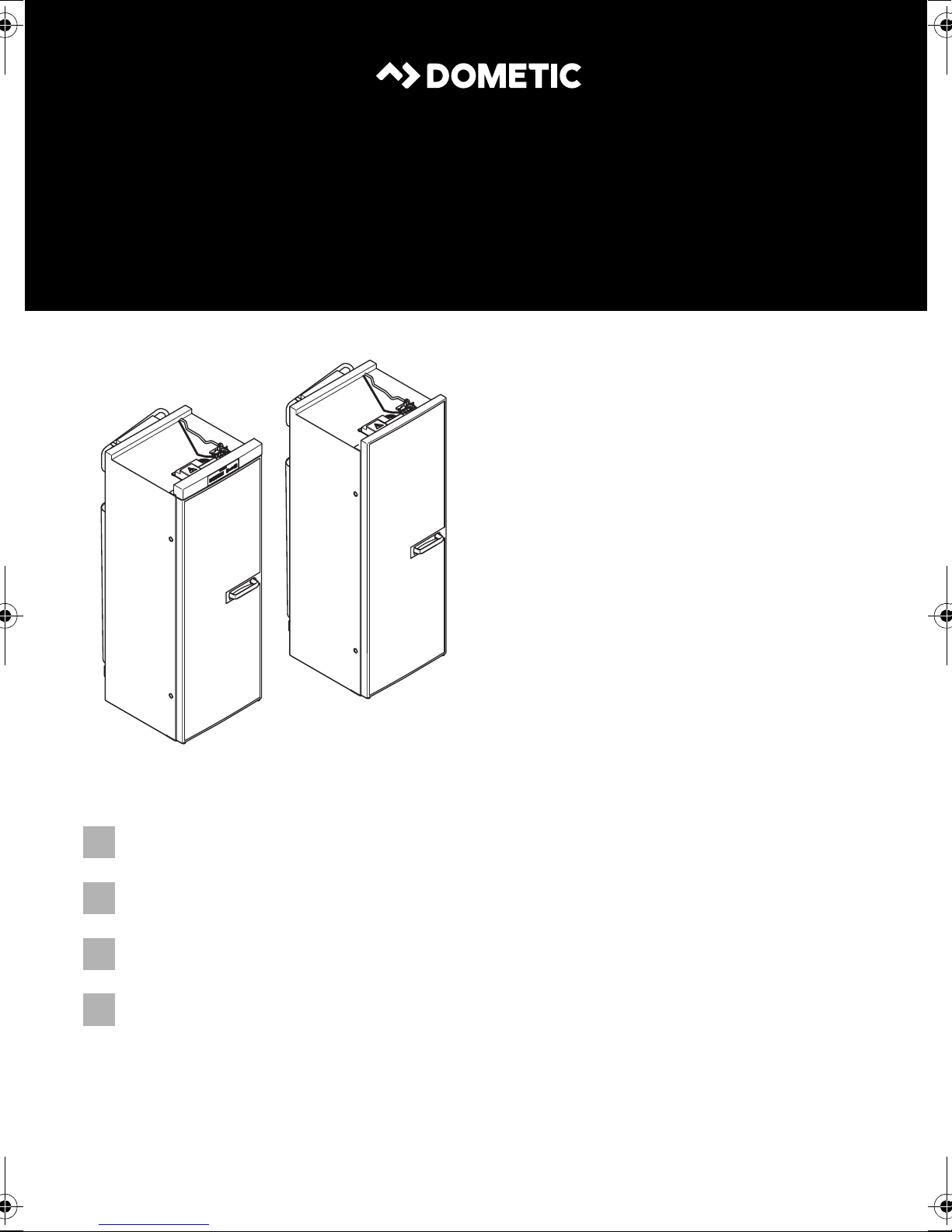
RML943x
RML933x
ENDEFR
NL
REFRIGERATION
9 SERIES
RML9330, RML9331, RML9335
RML9430, RML9431, RML9435
Absorber refrigerator
Installation Manual. . . . . . . . . . . . . . . . . . . . 14
Absorber-Kühlschrank
Montageanleitung. . . . . . . . . . . . . . . . . . . . 31
Réfrigérateur à absorption
Instructions de montage . . . . . . . . . . . . . . .49
Absorptiekoelkast
Montagehandleiding . . . . . . . . . . . . . . . . .69
Page 2
Page 3
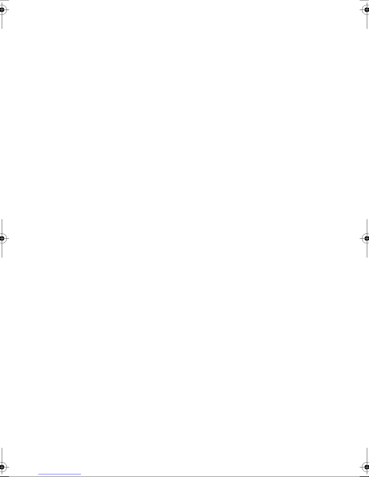
RML9xxx
1
586,5 mm420 mm
1293 mm
RML 9330, RML 9331, RML 9335
553 mm
468 mm
1293 mm
RML 9430, RML 9431, RML 9435
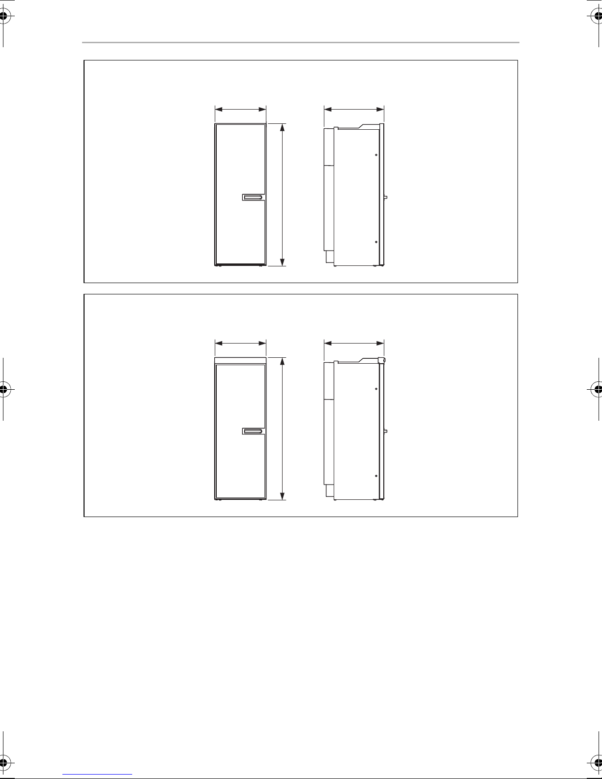
2
3
Page 4
RML9xxx
2
3
4
1
3
≥ 1050
< 1050
1
4
4
Page 5
RML9xxx
15 – 25 mm
> 25 mm
> 25 mm
5
≥ 1350
15 – 25 mm
1
6
5
Page 6
RML9xxx
≥ 300
1 2
7
918
1
2
3
4
1
3
2
4
LS 230 LS 330
0
6
Page 7
RML9xxx
a
b
LS 230
LS 330
1.
2.
3.
c
d
LS 230
LS 330
LS 230
LS 330
1
2
7
Page 8
1.
e
f
1
2
3
4
g
h
1.
2.
3.
RML 9430
i
1.
3.
2.
RML 9431, RML 9435
j
RML9xxx
2.
1
2
8
Page 9
RML9xxx
k
l
n2xm
p
o
q
2.
1.
2x
9
Page 10
RML9xxx
r
s
SW 17
SW 14
t
AB
1270,5
402
189
≤ 2,5
49583,5
49583,5
402
1216
1270,5
189
≤ 2,5
448
46
194,5
≤ 2,5
A B
1.
2.
3.
10
Page 11
RML9xxx
u
rt
+
1
2
15
br
87
85 86
30
14
ws
br
ws
ws
_
3
4
5
_
sw
bl
+
gn
ws
br
ge
ws
+
br
6
br
78
ws
rt
sw
br
12
bl
sw
6a
6b
4a
4b
ws
2a
br
2b
10
rt
11
5b
5a
3b
3a
1b
1a
ge
gn
br
br
bl
bl
br br
bl bl
10
ge/gn
ge
E
L
F
G
9
N
10
ge/gn
V85
br
br
13
ge/gn
bl br ge gn rt sw ws
EN Blue Brown Yellow Green Red Black White
DE Blau Braun Gelb Grün Rot Schwarz Weiß
FR Bleu Marron Jaune Vert Rouge Noir Blanc
NL Blauw Bruin Geel Groen Rood Zwart Wit
11
Page 12
RML9xxx
v
1
12
2
NL
L
N
15
3
LLNN
IN OUT
AC
TO GV 12VDCOUT
TO FC
TOP
4
14
rt
ABS
11
(+)
HE OUT 12 VDC HE IN
(-)
brbrbrws
(-)
(+)
6
13
(-)
rt
S+D+(+)
9
sw
A
10
BCDE FG
8
br rt sw ws
EN Brown Red Black White
DE Braun Rot Schwarz Weiß
FR Marron Rouge Noir Blanc
NL Bruin Rood Zwart Wit
7
5
sw
rt
12
Page 13
RML9xxx
RML 93…
RML 94…
w
13
Page 14
EN
Explanation of symbols RML9xxx
Please read this instruction manual carefully before installation and first
use, and store it in a safe place. If you pass on the product to another
person, hand over this instruction manual along with it.
NOTE
You can find details on the operation in the manual.
I
Table of contents
1 Explanation of symbols . . . . . . . . . . . . . . . . . . . . . . . . . . . . . . . . . . . . . . . . . .14
2 Safety instructions . . . . . . . . . . . . . . . . . . . . . . . . . . . . . . . . . . . . . . . . . . . . . .15
3 Scope of delivery . . . . . . . . . . . . . . . . . . . . . . . . . . . . . . . . . . . . . . . . . . . . . .16
4 Accessories . . . . . . . . . . . . . . . . . . . . . . . . . . . . . . . . . . . . . . . . . . . . . . . . . . .17
5 Intended use . . . . . . . . . . . . . . . . . . . . . . . . . . . . . . . . . . . . . . . . . . . . . . . . . .17
6 Installing the refrigerator. . . . . . . . . . . . . . . . . . . . . . . . . . . . . . . . . . . . . . . . .17
7 Connecting the refrigerator . . . . . . . . . . . . . . . . . . . . . . . . . . . . . . . . . . . . . 24
8 Technical data . . . . . . . . . . . . . . . . . . . . . . . . . . . . . . . . . . . . . . . . . . . . . . . . 29
1 Explanation of symbols
WARNING!
!
Safety instruction: Failure to observe this instruction can cause fatal or
serious injury.
CAUTION!
Safety instruction: Failure to observe this instruction can lead to injury.
!
NOTICE!
A
Failure to observe this instruction can cause material damage and impair
the function of the product.
NOTE
Supplementary information for operating the product.
I
14
Page 15
EN
RML9xxx Safety instructions
2 Safety instructions
The manufacturer accepts no liability for damage in the following cases:
• Faulty assembly or connection
• Damage to the product resulting from mechanical influences and excess voltage
• Alterations to the product without express permission from the manufacturer
• Use for purposes other than those described in the operating manual
WARNING!
!
• Never open the absorber unit. It is under high pressure and can cause
injury if it is opened.
• Ensure clean and residue-free handling if silicon sealant or similar is
used. There is a risk of fire if silicone filaments come into contact with
hot parts or naked flames.
• Do not operate the refrigerator if it is visibly damaged.
• If the AC power cable for this refrigerator is damaged, it must be
replaced by the manufacturer, customer service or a similarly qualified
person in order to prevent safety hazards.
• Never use a naked flame to check the refrigerator for leaks.
• This refrigerator may only be repaired by qualified personnel. Inade-
quate repairs may cause serious hazards.
• Only use propane or butane gas (not natural gas).
• Only operate the refrigerator at the pressure shown on the type
plate. Only use pressure controllers with a fixed setting which comply
with the national regulations (in Europe EN 12864).
• Dismantle all refrigerator doors for the disposal of the old refrigerator
and leave the shelves in the refrigerator to prevent accidental enclosure and suffocation.
CAUTION!
• Danger of crushing! Do not put your fingers into the hinge.
!
• Before starting the device, ensure that the power supply line and the
plug are dry.
NOTICE!
A
• Only hold the refrigerator at the body of the refrigerator during transport. Never hold the refrigerator at the absorber unit, the cooling fins,
the gas pipes, the door or the control panel.
15
Page 16

EN
Scope of delivery RML9xxx
• Make sure that the refrigerator circuit is not damaged during transportation. The refrigerant in the refrigerator circuit is highly flammable.
In the event of any damage to the refrigerator circuit (smell of ammonia):
– Switch off the refrigerator if applicable.
– Avoid naked flames and sparks.
– Air the room well.
• Do not install the refrigerator near naked flames or other heat sources
(heaters, direct sunlight, gas ovens etc.).
• Danger of overheating!
Always ensure sufficient ventilation so that the heat generated during
operation can dissipate. Make sure that the refrigerator is sufficiently
far away from walls and other objects so that the air can circulate.
• Check that the voltage specification on the type plate is the same as
that of the power supply.
• Do not open the refrigerant circuit under any circumstances.
• Only use the AC connection cable supplied to connect the refrigera-
tor to the AC mains.
• Only use cables with a suitable size.
• Never pull the plug out of the socket by the connection cable.
• The refrigerator may not be exposed to rain.
3Scope of delivery
• Refrigerator
• Ice-cube tray
• Operating manual
• Installation manual
16
Page 17
EN
RML9xxx Accessories
4Accessories
Available as accessories (not included in the scope of delivery):
Description
Fan kit for boosting the cooling capacity at high ambient temperatures
Ventilation grille
Winter cover for the ventilation grille
Divider, bottle finger (RML9430/9431/9435 only)
Shelf with safety edges (RML9430/9431/9435 only)
Door shelf locking
Bottle holder for door shelf locking
Shelf locking
All the accessories are available from specialist dealers. If you have any questions,
please contact the dealer or your service partner directly.
5 Intended use
The RML9330, RML9331, RML9335, RML9430, RML9431 and RML9435 refrigerators are designed for installation in caravans or motorhomes. They are only suitable
for cooling and storing foodstuffs. The refrigerators are not intended for the proper
storage of medicine.
The refrigerators are designed to be operated on a DC power supply and an
AC socket and can be independently powered by liquid gas (propane or butane).
The refrigerators may not be run on natural gas or city gas.
6 Installing the refrigerator
6.1 Preparing the installation
When installing the refrigerator, note the following:
• To enable the refrigerant to circulate properly, the refrigerator may not exceed an
angle of 3°.
To do this, park the vehicle on a level surface and check to see if the ice-cube tray
is flat in the refrigerator.
17
Page 18

EN
Installing the refrigerator RML9xxx
• The refrigerator must be installed so that it is easily accessible for service work,
easy to de-install and install and can be easily removed from the vehicle.
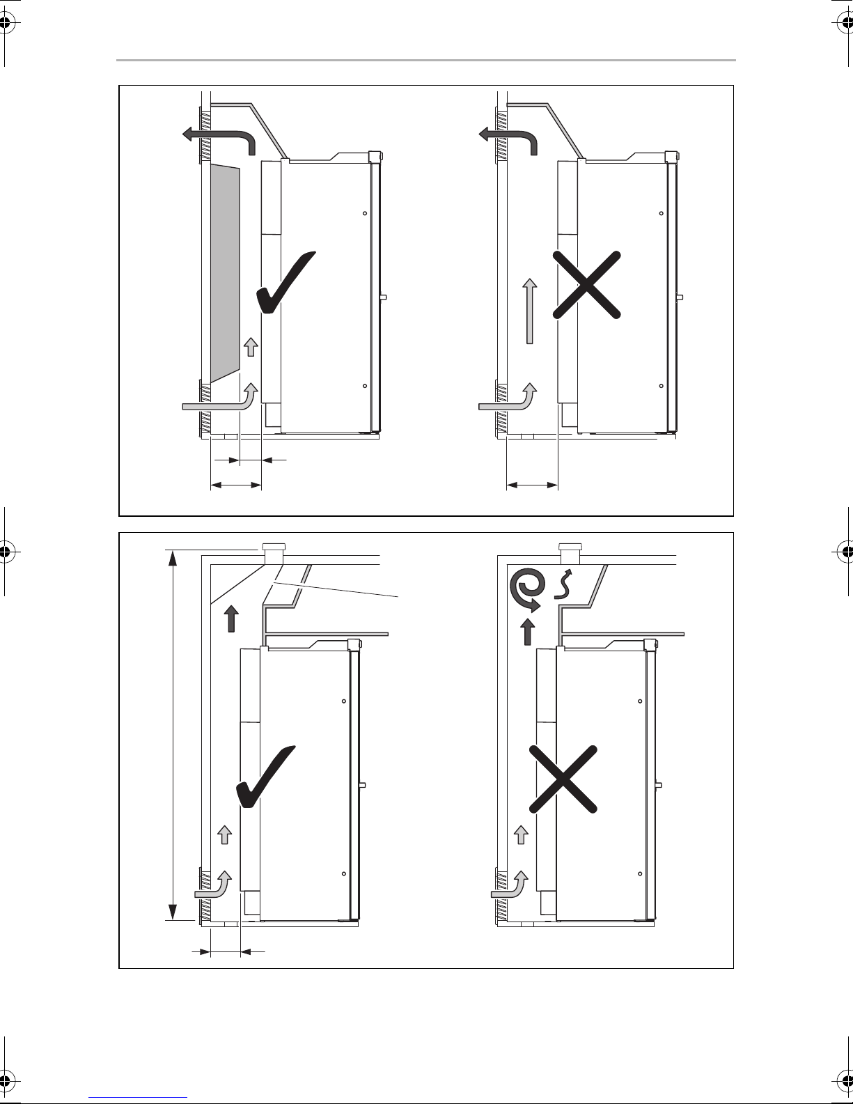
• The distance between the refrigerator and the rear wall must be min. 15 mm –
max. 25 mm (fig. 5, page 5).
• The refrigerator must be installed in a recess so that it stands firm when the vehicle
is in motion. Note the following dimensions here (H x W x D in mm):
– RML9330/9331/9335: 1293 x 420 x 586.5 (fig. 1, page 3)
– RML9430/9431/9435: 1293 x 468 x 553 (fig. 2, page 3)
• The outer wall must be fitted with an air inlet vent (fig. 3 1, page 4) and an outlet
vent (fig. 3 2, page 4) with ventilation grilles so that the heat generated can be
easily released to the outside:
– Air inlet vent: Fit the ventilation grille as flush as possible to the floor of the
installation niche with a minimum cross-section of 500 cm
2
.
– Outlet vent: fit as far above the refrigerator as possible.
– The distance between the air inlet and outlet vents must be at least 1050 mm
(fig. 4, page 4).
• Fit a heat conduction plate (fig. 3 3, page 4) above the refrigerator so that the
heat does not accumulate in the vehicle.
• If the ventilation grille of the air inlet vent cannot be installed flush to the ground,
an additional inlet vent (fig. 3 4, page 4) must be provided in the floor for
releasing leaked gas.
• A distance of more than 25 mm between the refrigerator and rear wall leads to
poor performance and increases the power consumption of the refrigerator.
Reduce the space behind the refrigerator to create adequate air inlet and outlet
ventilation (fig. 5, page 5). Use a ventilation plate, for example, to do this.
• If the minimum distance between the air inlet and outlet vents cannot be met, a
roof vent must be installed instead of the air outlet vent.
– The roof vent should be installed directly above the back of the refrigerator as
far as this is possible. Use an air duct (fig. 6 1, page 5) if you need to install
the roof vent offset, otherwise heat will accumulate there.
– The distance between the air inlet vent and the roof vent must be at least
1350 mm (fig. 6, page 5).
– If a roof air conditioner is provided, the distance between the roof vent
(fig. 7 1, page 6) and the air outlet of the roof air conditioner (fig. 7 2,
page 6) must be at least 300 mm.
• The refrigerator must not be installed at the side of the air inlet and outlet vents as
this leads to poor performance and increases the power consumption of the
refrigerator.
• The air inlet and outlet vents must not be covered by vehicle parts (such as an
open door or by installing accessories such as bicycle racks) while operating.
18
Page 19
EN
RML9xxx Installing the refrigerator
• Install the refrigerator so that it is protected from excessive heat, as this leads to
poor performance and increases the power consumption of the refrigerator.
• The electrical installation must comply with national and local regulations.
European standards: EN 60335-1, EN 60335-2-24, EN 1648-1 and EN 1648-2.
• The gas installation must comply with national and local regulations.
European standard: EN 1949.
• The refrigerator must be installed in a draught-proof location in accordance with
EN 1949, see chapter “Installing the refrigerator in a draught-proof location” on
page 19.
6.2 Installing the refrigerator in a draught-proof location
Gas-powered refrigerators in caravans or motorhomes must be installed in a
draught-free location according to EN 1949. This means that the combustion air is
not extracted from the interior and the exhaust fumes are prevented from directly
entering the living space.
A suitable seal must be fitted between the rear panel of the refrigerator and the
interior of the vehicle.
WARNING! Fire hazard!
!
The manufacturer recommends using a flexible seal to ease removal and installation
for maintenance purposes.
➤ Attach the sealing lips (fig. 8 1, page 6) to a stop rail behind the refrigerator, for
example, by using an adhesive.
➤ When installing, push the refrigerator against the stop rails with the sealing lips.
This then seals the space behind the refrigerator to the interior of the vehicle.
Do not use flammable materials such as silicone sealants, foam or similar
for the draught-proof installation.
19
Page 20
EN
Installing the refrigerator RML9xxx
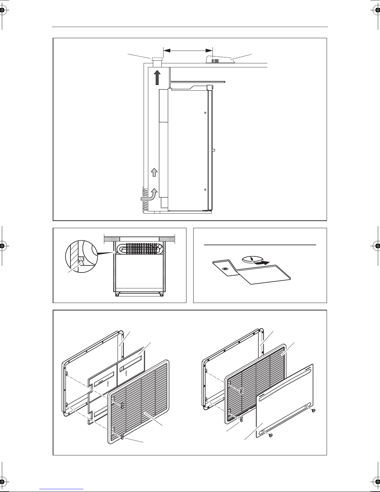
6.3 Making air inlet and outlet vents
NOTE
I
➤ Make an air inlet vent and an air outlet vent in the outer wall with the size of
410 mm x 249 mm. When doing so, observe the information, see chapter “Preparing the installation” on page 17.
If the ventilation grille of the air inlet vent cannot be installed flush with the floor of the
niche, you need to install an inlet vent in the floor:
➤ Make an air inlet vent in the floor (fig. 3 4, page 4) behind the refrigerator near
the gas burner.
At high ambient temperatures, the refrigerator can only provide its
maximum cooling capacity if the optimum ventilation has been
provided.
➤ Shield the end of the opening with a deflector to prevent sludge or dirt from get-
ting inside while driving (fig. 9, page 6).
If you have to use a roof vent instead of the air outlet vent:
➤ Cut out a section in the roof. Refer to the roof vent instruction manual for the
required dimensions. When doing so, observe the information, see chapter “Preparing the installation” on page 17.
20
Page 21
EN
RML9xxx Installing the refrigerator
6.4 Installing the ventilation grille
No. in
fig. 0, page 6
1 Installation frame
2 Ventilation grille
3 Winter cover
4Slider
Description
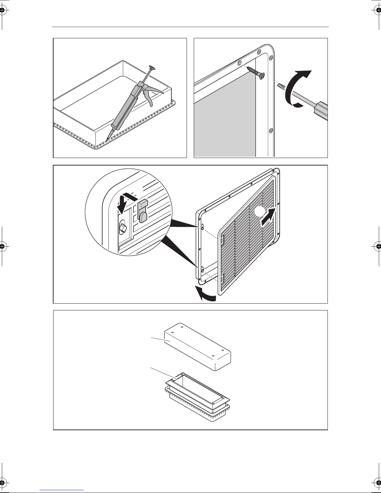
➤ Ensure the installation frame is water resistant (fig. a, page 7).
➤ Insert the installation frame and screw it down tightly (fig. b, page 7).
➤ Fit the ventilation grille (fig. c, page 7).
➤ Insert the slider and lock the ventilation grille with it (fig. c, page 7).
6.5 Install the roof vent
No. in
fig. d, page 7
Description
1 Installation frame
2 Hood
➤ Ensure the installation frame is water resistant (fig. e, page 8).
➤ Insert the installation frame and screw it down tightly (fig. e, page 8).
➤ Insert the hood and screw it down tightly (fig. f, page 8).
21
Page 22
EN
Installing the refrigerator RML9xxx
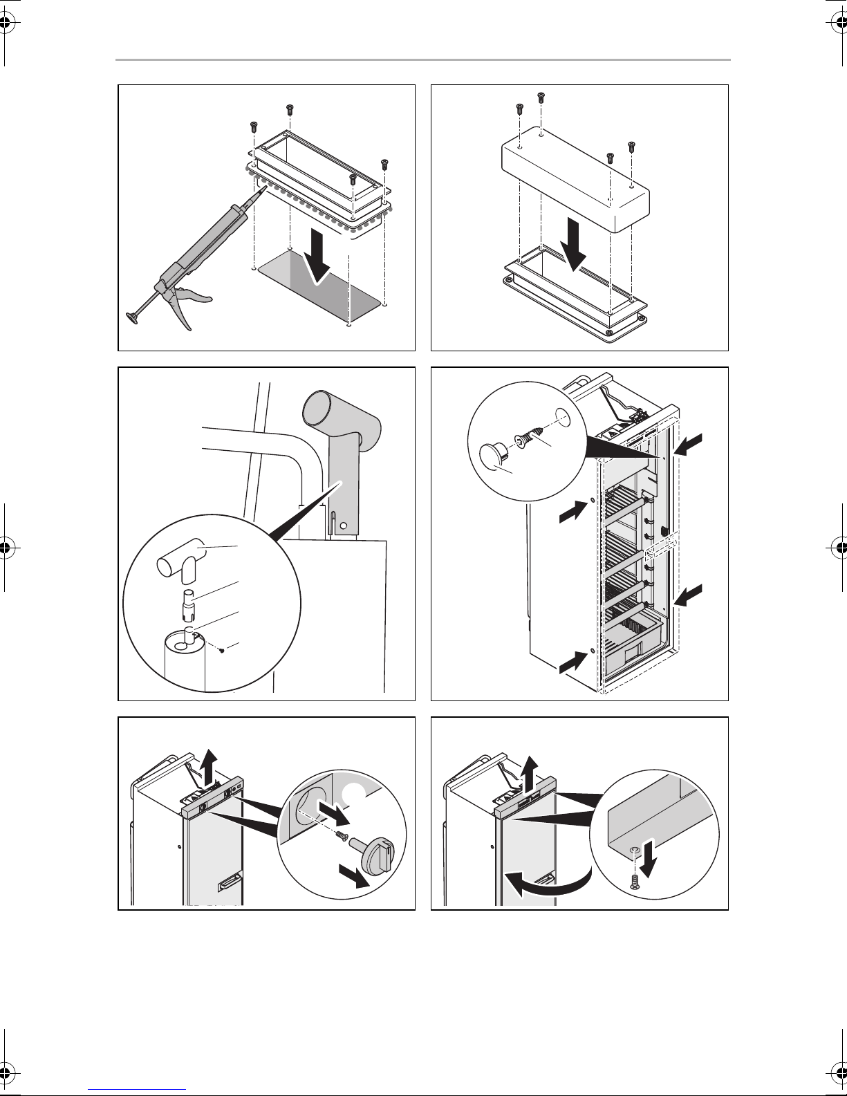
6.6 Install the flue duct
NOTE
I
The flue duct is installed at the factory. Follow these steps when you have removed
the flue duct and want to reinstall it (fig. g, page 8):
➤ Place the T-piece (1) on the adaptor (2) and the flue pipe (3).
➤ Direct the T-piece at an angle of 45° towards the rear wall.
➤ Attach the T-piece, adaptor and flue pipe with a screw (4).
6.7 Securing the refrigerator
!
Do not install an additional flue stack, as this leads to poor performance
and increases the power consumption of the refrigerator.
CAUTION!
Only drill through the receptacles provided, otherwise foamed
components, including cables, can be damaged.
NOTE
I
Proceed as follows (fig. h, page 8):
➤ Move the refrigerator into its final location.
➤ Fasten the four screws (1) through the four plastic washers in the sides of the
refrigerator, and further into the wall.
➤ Put the caps (2) onto the screw heads.
Attach the side walls or the attached strips so that the screws are tight,
even when under increased loads (while driving).
22
Page 23
EN
RML9xxx Installing the refrigerator
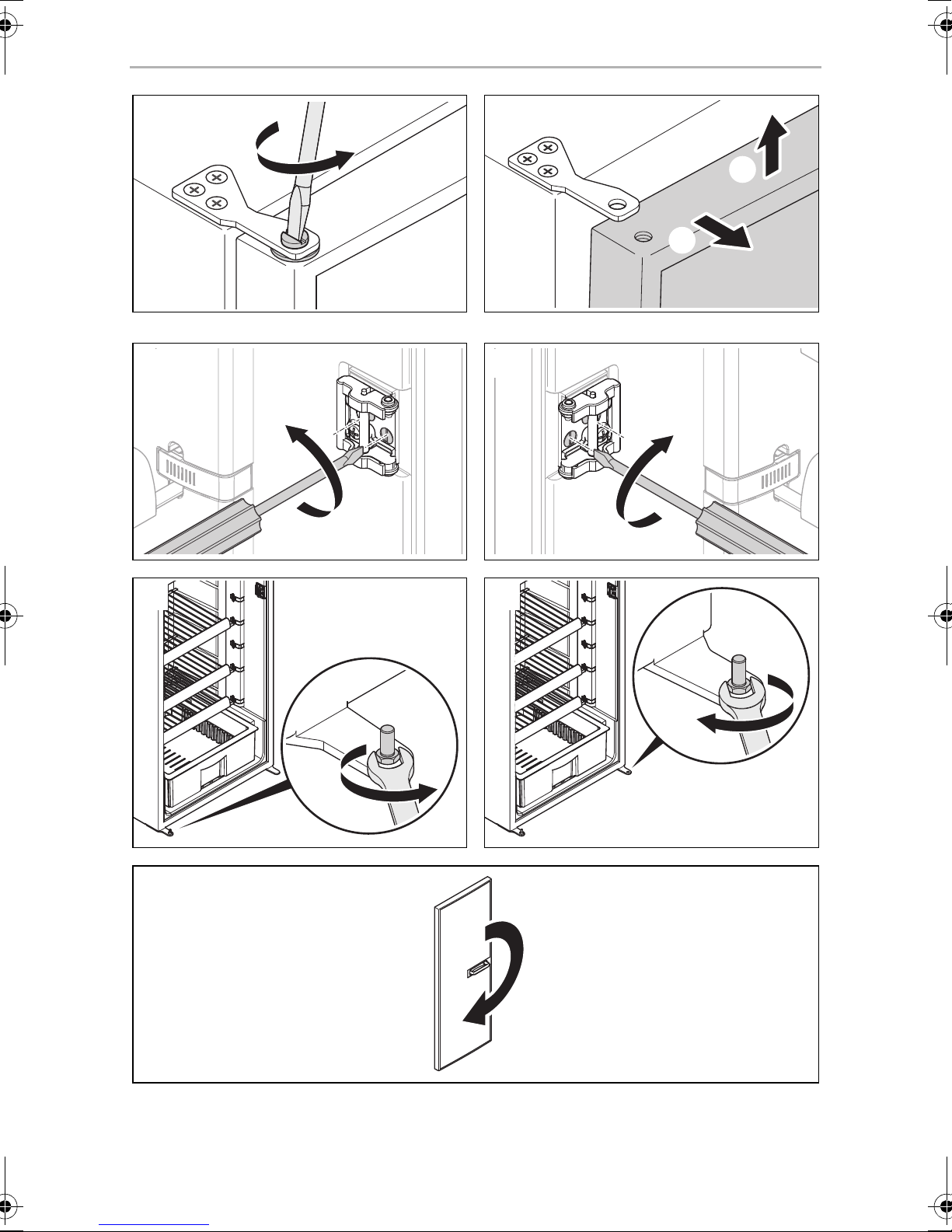
6.8 Reversing the door (RML9430/9431/9435 only)
➤ Remove the control panel.
– RML9430: Unscrew the dials carefully and loosen the screws (fig. i,
page 8).
– RML9431/9435: Open the refrigerator door and undo the screws
underneath the control panel (fig. j, page 8).
➤ Undo the hinge screw on the top door hinge and keep it in a safe place (fig. k,
page 9).
➤ Lift up the door and remove it (fig. l, page 9).
➤ Undo the two screws on the door lock and remove the door lock (fig. m,
page 9).
➤ Place the door lock on the other side again and tighten it with the two screws
(fig. n, page 9).
➤ Undo the hinge pin (fig. o, page 9) and position it on the other side (fig. p,
page 9).
➤ Turn the door by 180° (fig. q, page 9).
➤ Place the door on the hinge pin.
➤ Replace the control panel and screw it down tightly.
6.9 Put on the door panel
NOTICE! Beware of damage
A
The door panel has the following dimensions (fig. r, page 10):
• RML9330/9331/9335: A
• RML9430/9431/9435: B
Proceed as follows (fig. s, page 10):
➤ Remove the door trim carefully. It is only stuck on and held by small hooks (A).
Only ever lay the refrigerator on its side and never on its back. Otherwise
the unit may be damaged.
➤ Slide the new panel into the opening (B).
➤ Replace the door trim (B).
✓ The door trim is secure once it clicks into place.
23
Page 24
EN
Connecting the refrigerator RML9xxx
If you have laid the refrigerator on its side to insert the panel:
➤ Wait a few minutes before you switch on the refrigerator.
7 Connecting the refrigerator
7.1 Connecting to the gas supply
NOTICE!
A
• This refrigerator may only be connected to the gas supply by a
specialist in accordance with the applicable guidelines and
standards.
• Only use cylinders of propane or butane gas (not natural gas or city
gas) with an approved pressure reduction valve and suitable head.
Compare the pressure information on the type plate with the
pressure information on the pressure regulator on the propane or
butane gas cylinder.
• Only operate the refrigerator at the pressure shown on the type
plate.
• Please note the pressures which are permitted in your country. Use a
DIN-DVGW-approved pressure regulator with a fixed setting:
– The following applies for Germany: DIN EN 12864
– The following applies for Europe: EN 732 and EN 1949
NOTE
I
It must be possible to shut off the refrigerator from the gas line separately by means
of a shut-off device. The shut-off device must be easily accessible.
➤ Connect the refrigerator securely by hand to the gas supply (fig. t, page 10).
The following applies for Europe: Use a cutting ring fitting in accordance with
EN 1949.
A hose connection is not permitted.
➤ Have a leak test and a flame test performed in accordance with EN 1949 by an
authorised specialist.
Ensure you are issued with a certificate of inspection.
The refrigerator is equipped for a connection pressure of 30 mbar. Use
a 50/30 mbar pressure regulator when connected to a 50 mbar system.
24
Page 25
EN
RML9xxx Connecting the refrigerator
7.2 Connecting to 12 Vg and 230 Vw
NOTICE!
A
I
• The electrical installation and repairs may only be performed by a
specialist in accordance with the applicable regulations and
standards.
• According to EN 1648-1, the respective negative and positive cables
of the DC connections for heating and lighting may not be joined
with one another in a caravan. This can cause electrical interference
or damage to electrical components.
• The inverter may only be connected by a specialist.
NOTE
• The mains socket must be easily accessible so that you can unplug
the power cord if required, thereby disconnecting the refrigerator
from the power.
• The plug of the AC connection cable must not be cut off.
• The connection cables must be laid so that they do not come in
contact with hot parts of the unit/burner or with sharp edges.
• Changes to the internal electrical installation or the connection of
other electrical components (e.g. extra third party fans) to the
internal wiring of the refrigerator will void the E1/CE approval and
any claims from the guarantee and product liability.
25
Page 26
EN
Connecting the refrigerator RML9xxx
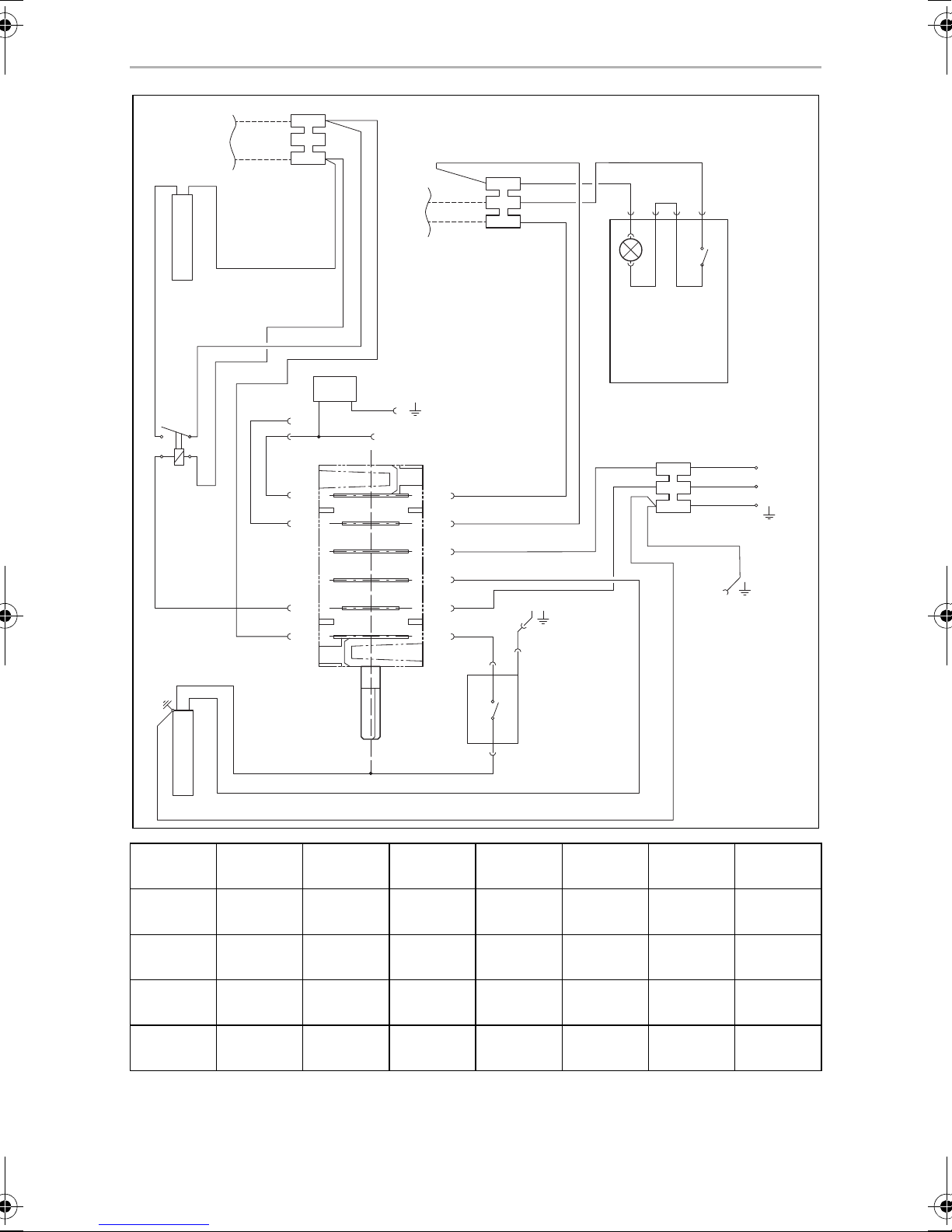
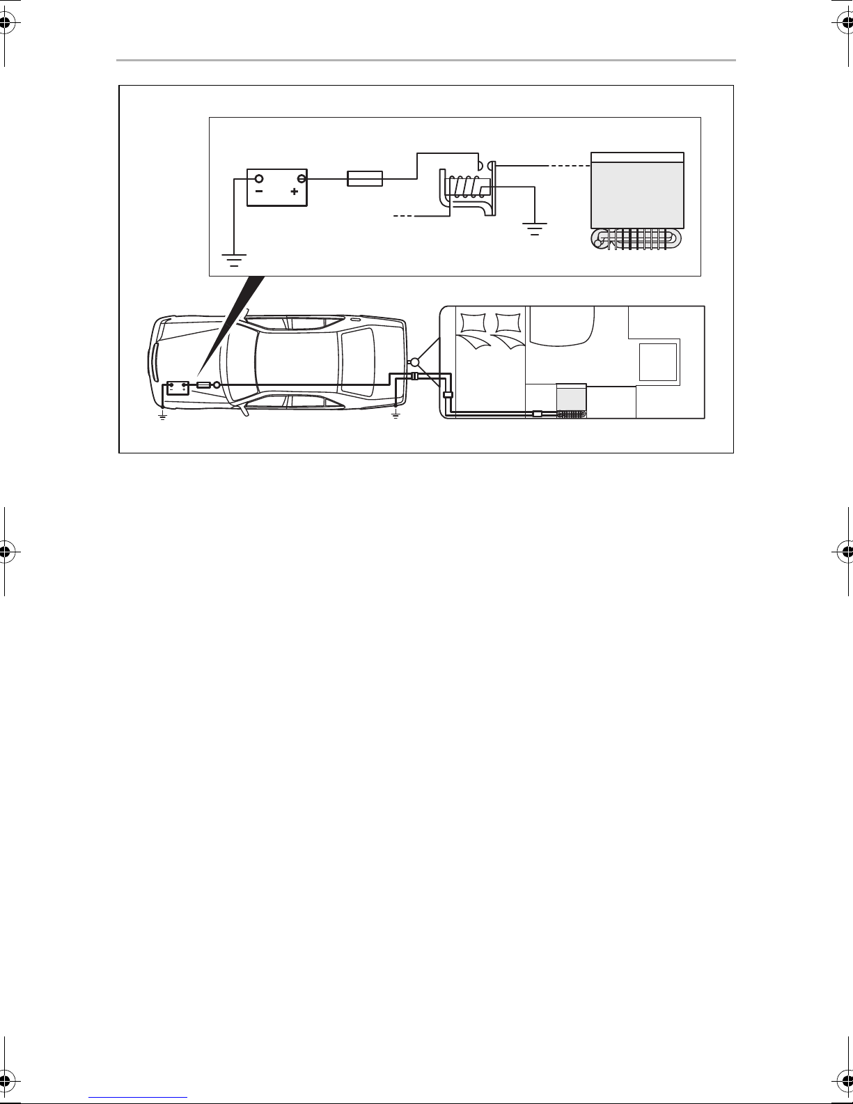
➤ Connect the RML9330/9430 refrigerators as follows (fig. u, page 11).
Item Description
1 Heating element positive terminal (+) DC power
2 Heating element earth terminal DC power
3 Heating cartridge terminal strip DC power
4 Lighting negative terminal (–)
5 Lighting positive terminal (+)
6 Lighting terminal strip DC power
7 LED lighting DC power
8 LED lighting switch
9 AC power connection cable
10 Earth housing (upper section)
11 Thermal power adapter
12 Galvanometer
13 Heating cartridge AC power
14 Relay 30 A
15 Heating cartridge DC power
26
Page 27
EN
RML9xxx Connecting the refrigerator
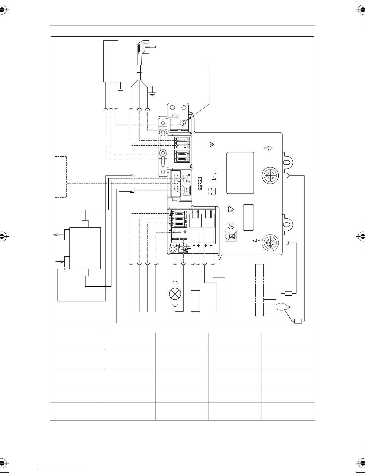
➤ Connect the RML9331/9335/9431/9435 refrigerators as follows (fig. v,
page 12):
Item Description
1 Heating cartridge AC power
2 AC power connection cable
3 Earth AC power
4 Ionisation
5 Ignition
6Burner
7 Heating cartridge DC power supply
8 Heating cartridge DC power
9 LED lighting
10 Electronics DC power supply
11 Gas inlet
12 Gas outlet
13 Gas valve
14 DC power outlet
15 Gas valve supply line
A Optional connections to DC power outlet
B Negative terminal (–) DC permanent supply for electronics
C Positive terminal (+) DC permanent supply for electronics
D Connection D+
E Connection S+
F Heating element positive terminal (+) DC power
G Heating element earth terminal DC power
AC power:
➤ Connect the refrigerator with the mains plug to an AC socket.
27
Page 28

EN
Connecting the refrigerator RML9xxx
DC power:
Please note the following cable sizes:
– < 6m (interior): 6mm
– > 6 m (interior): 10 mm
– Connections D+ and S+: 1 mm
– Cable fed via drawbar (caravans only): 2.5 mm
2
2
2
2
➤ Secure the power supply line to the heating element (connection 4) with a
20 A fuse and the supply for lighting/electronics (connection 6) with a 2 A fuse.
➤ Connect the heating element (connections 3 and 4) with the shortest possible
cable.
➤ Run the cable to the heating element (connections 3 and 4) via a relay controlled
by an ignition socket to prevent the battery from completely discharging if the
engine is switched off accidentally (fig. w, page 13).
➤ RML9331/9335/9431/9435 only: Connect a 12 V continuous supply to the
connection for lighting/electronics (terminals 5 and 6).
D+ (RML9335/9435 only)
In automatic mode, the refrigerator selects the most favourable mode available. The
refrigerator is only operated with direct current when the vehicle engine is running.
The electronics of the refrigerator uses the signal D+ from the light system to detect
the running engine.
➤ Connect the D+ connection to the controls (fig. v D, page 12) with the
respective terminal of the vehicle.
S+ (RML9335/9435 only)
In automatic mode, the refrigerator is first powered with DC power from the vehicle's own solar system. The refrigerator electronics uses the S+ signal of the solar
charge controller to detect a solar system. The solar charge controller must have an
AES output.
➤ Connect the S+ connection on the controller (fig. w E, page 13) to the
respective terminal of the solar charge controller.
Suitable solar charge controllers are available from specialist dealers.
The manufacturer recommends, for example:
• Büttner MT 300-S
(www.buettner-elektronik.de)
• Votronic MPP 240 Duo Digital
(www.votronic.de)
28
Page 29

EN
RML9xxx Technical data
1
8 Technical data
RML9330 RML9331 RML9335
Voltage: 230 Vw / 50 Hz
12 Vg
Gross capacity: 134 l
Ice compartment: 12 l
Gross capacity
(excluding ice compartment):
Net capacity: 129 l
Net capacity
(excluding ice compartment):
Power consumption: 170 W (230 Vw)
Power consumption: 3.2 kWh/24 h (230 Vw)
340 Ah/24 h (12 Vg)
Gas consumption: 380 g/24 h
Climatic class: SN
Noise emission: 0 dB(A)
Ignition: Manual Automatic Automatic
Power choice: Manual Manual Automatic
Dimensions: fig. 1, page 3
138.5 l
133.5 l
170 W (12 Vg)
Weight: 37 kg
Inspection/certification:
NOTE
You can obtain the CE declaration of conformity at Dometic.
I
29
Page 30

EN
Technical data RML9xxx
1
RML9430 RML9431 RML9435
Voltage: 230 Vw / 50 Hz
12 Vg
Gross capacity: 146 l
Ice compartment: 12 l
Gross capacity
(excluding ice compartment):
Net capacity: 142 l
Net capacity
(excluding ice compartment):
Power consumption: 170 W (230 Vw)
Power consumption: 3.2 kWh/24 h (230 Vw)
340 Ah/24 h (12 Vg)
Gas consumption: 380 g/24 h
Climatic class: SN
Noise emission: 0 dB(A)
Ignition: Manual Automatic Automatic
Power choice: Manual Manual Automatic
Dimensions: fig. 2, page 3
151 l
148 l
170 W (12 Vg)
Weight: 37 kg
Inspection/certification:
NOTE
You can obtain the CE declaration of conformity at Dometic.
I
30
Page 31

DE
RML9xxx Erklärung der Symbole
Bitte lesen Sie diese Anleitung vor Einbau und Inbetriebnahme sorgfältig
durch und bewahren Sie sie auf. Geben Sie sie im Falle einer Weitergabe
des Produktes an den Nutzer weiter.
HINWEIS
Hinweise zur Bedienung finden Sie in der Bedienungsanleitung.
I
Inhaltsverzeichnis
1 Erklärung der Symbole . . . . . . . . . . . . . . . . . . . . . . . . . . . . . . . . . . . . . . . . . .31
2 Sicherheitshinweise . . . . . . . . . . . . . . . . . . . . . . . . . . . . . . . . . . . . . . . . . . . 32
3 Lieferumfang . . . . . . . . . . . . . . . . . . . . . . . . . . . . . . . . . . . . . . . . . . . . . . . . . 33
4 Zubehör. . . . . . . . . . . . . . . . . . . . . . . . . . . . . . . . . . . . . . . . . . . . . . . . . . . . . 34
5 Bestimmungsgemäßer Gebrauch . . . . . . . . . . . . . . . . . . . . . . . . . . . . . . . . 34
6 Kühlschrank einbauen. . . . . . . . . . . . . . . . . . . . . . . . . . . . . . . . . . . . . . . . . . 35
7 Kühlschrank anschließen . . . . . . . . . . . . . . . . . . . . . . . . . . . . . . . . . . . . . . . 42
8 Technische Daten . . . . . . . . . . . . . . . . . . . . . . . . . . . . . . . . . . . . . . . . . . . . . 47
1 Erklärung der Symbole
WARNUNG!
!
Sicherheitshinweis: Nichtbeachtung kann zu Tod oder schwerer
Verletzung führen.
VORSICHT!
Sicherheitshinweis: Nichtbeachtung kann zu Verletzungen führen.
!
ACHTUNG!
A
Nichtbeachtung kann zu Materialschäden führen und die Funktion des
Produktes beeinträchtigen.
HINWEIS
Ergänzende Informationen zur Bedienung des Produktes.
I
31
Page 32

DE
Sicherheitshinweise RML9xxx
2 Sicherheitshinweise
Der Hersteller übernimmt in folgenden Fällen keine Haftung für Schäden:
• Montage- oder Anschlussfehler
• Beschädigungen am Produkt durch mechanische Einflüsse und Über-
spannungen
• Veränderungen am Produkt ohne ausdrückliche Genehmigung vom Hersteller
• Verwendung für andere als die in der Anleitung beschriebenen Zwecke
WARNUNG!
!
• Öffnen Sie niemals das Absorberaggregat. Es steht unter hohem
Druck und kann Verletzungen verursachen, wenn es geöffnet wird.
• Achten Sie auf eine saubere und rückstandsfreie Verarbeitung, wenn
Silikon-Dichtungsmasse o. Ä. verwendet wird. Kommen Silikonfäden
mit heißen Teilen oder offenen Flammen in Berührung, besteht Brandgefahr.
• Wenn der Kühlschrank sichtbare Beschädigungen aufweist, dürfen
Sie ihn nicht in Betrieb nehmen.
• Wenn das Wechselstrom-Anschlusskabel dieses Kühlschranks
beschädigt wird, muss es durch den Hersteller, seinen Kundendienst
oder eine ähnlich qualifizierte Person ersetzt werden, um Gefährdungen zu vermeiden.
• Prüfen Sie den Kühlschrank niemals mit einer offenen Flamme auf
Undichtigkeit.
• Reparaturen an diesem Kühlschrank dürfen nur von Fachkräften durchgeführt werden. Durch unsachgemäße Reparaturen können erhebliche Gefahren entstehen.
• Verwenden Sie nur Propan- oder Butangas (kein Erdgas).
• Der Kühlschrank darf ausschließlich mit dem auf dem Typenschild
angegebenen Druck betrieben werden. Verwenden Sie nur festeingestellte Druckregler, die den nationalen Vorschriften entsprechen
(in Europa EN 12864).
• Demontieren Sie alle Kühlschranktüren bei Entsorgung des Altkühlschranks und belassen Sie die Ablagen im Kühlschrank, um ein
versehentliches Einschließen und Ersticken zu verhindern.
32
Page 33

DE
RML9xxx Lieferumfang
VORSICHT!
!
A
• Quetschgefahr! Fassen Sie nicht in das Scharnier.
• Achten Sie vor der Inbetriebnahme darauf, dass Zuleitung und Stecker
trocken sind.
ACHTUNG!
• Halten Sie den Kühlschrank beim Transport nur am Kühlschrankkorpus
fest. Halten Sie den Kühlschrank niemals am Absorberaggregat, den
Kühlrippen, den Gasleitungen, der Tür oder der Bedienblende fest.
• Achten Sie beim Transport darauf, den Kühlkreislauf nicht zu
beschädigen. Das Kältemittel im Kühlkreislauf ist leicht entflammbar.
Bei einer Beschädigung des Kühlkreislaufs (Ammoniakgeruch):
– Schalten Sie gegebenenfalls den Kühlschrank aus.
– Vermeiden Sie offenes Feuer und Zündfunken.
–Lüften Sie den Raum gut.
• Bauen Sie den Kühlschrank nicht in der Nähe von offenen Flammen
oder anderen Wärmequellen (Heizung, Gasöfen usw.) ein.
• Überhitzungsgefahr!
Achten Sie stets darauf, dass beim Betrieb entstehende Wärme ausreichend abgeführt werden kann. Sorgen Sie dafür, dass der Kühlschrank in ausreichendem Abstand zu Wänden oder Gegenständen
steht, sodass die Luft zirkulieren kann.
• Vergleichen Sie die Spannungsangabe auf dem Typenschild mit der
vorhandenen Energieversorgung.
• Öffnen Sie auf keinen Fall den Kühlkreislauf.
• Schließen Sie den Kühlschrank nur mit dem zugehörigen Wechsel-
strom-Anschlusskabel an die Wechselstromsteckdose an.
• Verwenden Sie nur Kabel mit passendem Leitungsquerschnitt.
• Ziehen Sie den Stecker nie am Anschlusskabel aus der Steckdose.
• Der Kühlschrank darf keinem Regen ausgesetzt werden.
3 Lieferumfang
• Kühlschrank
• Eiswürfelschale
• Bedienungsanleitung
• Montageanleitung
33
Page 34

DE
Zubehör RML9xxx
4Zubehör
Als Zubehör erhältlich (nicht im Lieferumfang enthalten):
Bezeichnung
Lüfterkit zur Steigerung der Kühlleistung bei hohen Außentemperaturen
Lüftungsgitter
Winterabdeckung für das Lüftungsgitter
Teiler, Flaschenfinger (nur RML9430/9431/9435)
Tragrost mit Kantenschutz (nur RML9430/9431/9435)
Arretierbare Türetagere
Flaschenhalter für arretierbare Türetagere
Arretierbare Tragroste
Sämtliche Zubehöre sind über den Fachhandel erhältlich. Bei Fragen wenden Sie
sich bitte direkt an den Fachhandel oder Ihren Service-Partner.
5 Bestimmungsgemäßer Gebrauch
Die Kühlschränke RML9330, RML9331, RML9335, RML9430, RML9431 und
RML9435 sind für den Einbau in Wohnwagen oder Wohnmobile ausgelegt. Sie
eignen sich ausschließlich zum Kühlen und Lagern von Lebensmitteln. Die Kühlschränke sind nicht für die fachgerechte Lagerung von Medikamenten vorgesehen.
Die Kühlschränke sind für den Betrieb am Gleichstromnetz und an einer Wechselstromsteckdose ausgelegt und können stromunabhängig mit Flüssiggas (Propan
oder Butan) betrieben werden. Die Kühlschränke dürfen nicht mit Erdgas oder
Stadtgas betrieben werden.
34
Page 35

DE
RML9xxx Kühlschrank einbauen
6Kühlschrank einbauen
6.1 Einbau vorbereiten
Beachten Sie bei der Montage des Kühlschranks folgende Hinweise:
• Damit das Kältemittel ordnungsgemäß zirkulieren kann, darf der Kühlschrank
einen Neigungswinkel von 3° nicht überschreiten.
Stellen Sie hierzu das Fahrzeug waagerecht ab und prüfen Sie, ob die Eiswürfelschale eben im Kühlschrank liegt.
• Der Kühlschrank muss so eingebaut werden, dass er für Servicearbeiten gut
zugänglich ist, leicht aus- und eingebaut und ohne großen Aufwand aus dem
Fahrzeug entnommen werden kann.
• Der Abstand zwischen Kühlschrank und Rückwand muss min. 15 mm –
max. 25 mm betragen (Abb. 5, Seite 5).
• Der Kühlschrank muss in eine Nische eingebaut werden, damit er bei Bewegung
des Fahrzeugs fest steht. Beachten Sie hierzu folgende Abmessungen
(H x B x T in mm):
– RML9330/9331/9335: 1293 x 420 x 586,5 (Abb. 1, Seite 3)
– RML9430/9431/9435: 1293 x 468 x 553 (Abb. 2, Seite 3)
• In der Außenwand muss eine Belüftungsöffnung (Abb. 3 1, Seite 4) und eine
Entlüftungsöffnung (Abb. 3 2, Seite 4) mit Lüftungsgitter vorgesehen werden,
damit die entstehende Wärme gut nach außen abgegeben werden kann:
– Belüftungsöffnung: Lüftungsgitter möglichst bündig zum Boden der Einbau-
nische mit einem Querschnitt von mindestens 500 cm
– Entlüftungsöffnung: möglichst weit oberhalb des Kühlschranks.
– Der Abstand zwischen Belüftungsöffnung und Entlüftungsöffnung muss
mindestens 1050 mm betragen (Abb. 4, Seite 4).
• Sehen Sie oberhalb des Kühlschranks ein Wärmeleitblech vor (Abb. 3 3,
Seite 4), damit sich die Wärme nicht im Fahrzeug staut.
• Falls das Lüftungsgitter der Belüftungsöffnung nicht bündig zum Boden eingebaut werden kann, muss zusätzlich eine Belüftungsöffnung (Abb. 3 4, Seite 4)
im Fußboden zum Abführen von ausgetretenem Gas vorgesehen werden.
• Ein Abstand von über 25 mm zwischen Kühlschrank und Rückwand führt zu
Leistungseinbußen und erhöhtem Energieverbrauch des Kühlschranks.
Verkleinern Sie den Hohlraum hinter dem Kühlschrank entsprechend, um eine
ausreichende Be- und Entlüftung herzustellen (Abb. 5, Seite 5). Nutzen Sie
hierzu z. B. ein Luftleitblech.
2
.
35
Page 36

DE
Kühlschrank einbauen RML9xxx
• Falls der Mindestabstand zwischen Belüftungsöffnung und Entlüftungsöffnung
nicht eingehalten werden kann, muss statt der Entlüftungsöffnung ein Dachentlüfter verbaut werden.
– Der Dachentlüfter sollte möglichst direkt über der Rückseite des Kühlschranks
angebracht werden. Nutzen Sie einen Luftkanal (Abb. 6 1, Seite 5), wenn
Sie den Dachentlüfter versetzt anbringen müssen, da sonst ein Wärmestau
entsteht.
– Der Abstand zwischen Belüftungsöffnung und Dachentlüfter muss mindes-
tens 1350 mm betragen (Abb. 6, Seite 5).
– Falls eine Dachklimaanlage vorhanden ist, muss der Abstand zwischen
Dachentlüfter (Abb. 7 1, Seite 6) und Luftauslass der Dachklimaanlage
(Abb. 7 2, Seite 6) mindestens 300 mm betragen.
• Der Kühlschrank darf nicht seitlich zu den Be- und Entlüftungsöffnungen eingebaut werden, da dies zu Leistungseinbußen und erhöhtem Energieverbrauch
des Kühlschranks führt.
• Die Belüftungs- und Entlüftungsöffnung dürfen im Betrieb nicht durch Fahrzeugteile abgedeckt werden (z. B. geöffnete Tür oder durch den Anbau von Zubehör
wie Fahrradträger).
• Installieren Sie den Kühlschrank geschützt gegen übermäßige Wärmeeinstrahlung, da diese zu Leistungseinbußen und erhöhtem Energieverbrauch
des Kühlschranks führt.
• Die elektrische Installation muss nach den nationalen und örtlichen Vorschriften
erfolgen.
Europäische Normen: EN 60335-1, EN 60335-2-24, EN 1648-1 und EN 1648-2.
• Die Gas-Installation muss nach den nationalen und örtlichen Vorschriften
erfolgen.
Europäische Norm: EN 1949.
• Der Kühlschrank muss nach EN 1949 zugdicht eingebaut werden, siehe Kapitel
„Kühlschrank zugdicht einbauen“ auf Seite 37.
36
Page 37

DE
RML9xxx Kühlschrank einbauen
6.2 Kühlschrank zugdicht einbauen
Gasbetriebene Kühlschränke in Wohnwagen oder Wohnmobilen müssen nach
EN 1949 zugdicht eingebaut werden. Das bedeutet, dass die Verbrennungsluft
nicht dem Innenraum entnommen wird und die Abgase am direkten Eintritt in den
Wohnraum gehindert werden.
Zwischen Rückwand des Kühlschranks und dem Innenraum des Fahrzeugs muss
eine geeignete Abdichtung vorgesehen werden.
WARNUNG! Brandgefahr!
!
Der Hersteller empfiehlt, eine flexible Dichtung zu verwenden, um den Aus- und
Einbau zu Wartungszwecken zu vereinfachen.
Verwenden Sie zum zugdichten Einbau keine leicht entflammbaren
Materialien wie Silikon-Dichtungsmassen, Montageschaum oder
Ähnliches.
➤ Befestigen Sie die Dichtlippen (Abb. 8 1, Seite 6) an einer Anschlagleiste hinter
dem Kühlschrank, z. B. durch Kleben.
➤ Schieben Sie den Kühlschrank bei der Montage gegen die Anschlagleisten mit
den Dichtlippen. Dadurch ist der Raum hinter dem Kühlschrank zum Innenraum
des Fahrzeugs abgedichtet.
6.3 Be- und Entlüftungsöffnungen herstellen
HINWEIS
I
➤ Fertigen Sie eine Belüftungs- und eine Entlüftungsöffnung in der Außenwand mit
der Größe 410 mm x 249 mm an. Beachten Sie dabei die Hinweise, siehe
Kapitel „Einbau vorbereiten“ auf Seite 35.
Bei hohen Umgebungstemperaturen kann der Kühlschrank nur dann
seine maximale Kühlleistung erbringen, wenn für eine optimale Be- und
Entlüftung gesorgt ist.
37
Page 38

DE
Kühlschrank einbauen RML9xxx
Falls das Lüftungsgitter der Belüftungsöffnung nicht bündig zum Boden der Einbaunische eingebaut werden kann, müssen Sie eine Belüftungsöffnung im Fußboden
einbauen:
➤ Fertigen Sie hinter dem Kühlschrank im Bereich des Gasbrenners eine
Belüftungsöffnung im Boden an (Abb. 3 4, Seite 4).
➤ Schirmen Sie das Ende der Öffnung mit einem Ablenker ab, damit während der
Fahrt kein Schlamm oder Dreck eindringen kann (Abb. 9, Seite 6).
Falls Sie statt der Entlüftungsöffnung einen Dachentlüfter nutzen müssen:
➤ Fertigen Sie einen Rahmenausschnitt im Dach an. Entnehmen Sie das erforder-
liche Maß der Anleitung des Dachentlüfters. Beachten Sie dabei die Hinweise,
siehe Kapitel „Einbau vorbereiten“ auf Seite 35.
6.4 Lüftungsgitter montieren
Pos. in
Abb. 0, Seite 6
1 Einbaurahmen
2 Lüftungsgitter
3 Winterabdeckung
4Schieber
Bezeichnung
➤ Dichten Sie den Einbaurahmen wasserdicht ab (Abb. a, Seite 7).
➤ Setzen Sie den Einbaurahmen ein und schrauben Sie ihn fest (Abb. b, Seite 7).
➤ Setzen Sie das Lüftungsgitter ein (Abb. c, Seite 7).
➤ Setzen Sie die Schieber ein und verriegeln Sie mit ihnen das Lüftungsgitter
(Abb. c, Seite 7).
38
Page 39

DE
RML9xxx Kühlschrank einbauen
6.5 Dachentlüfter montieren
Pos. in
Abb. d, Seite 7
1 Einbaurahmen
2Haube
➤ Dichten Sie den Einbaurahmen wasserdicht ab (Abb. e, Seite 8).
➤ Setzen Sie den Einbaurahmen ein und schrauben Sie ihn fest (Abb. e, Seite 8).
➤ Setzen Sie die Haube auf und schrauben Sie sie fest (Abb. f, Seite 8).
6.6 Abgasführung montieren
HINWEIS
I
Die Abgasführung ist werkseitig montiert. Gehen Sie wie folgt vor, wenn Sie die
Abgasführung demontiert haben und wieder montieren wollen (Abb. g, Seite 8):
Setzen Sie keinen zusätzlichen Abgaskamin ein, da dies zu Leistungseinbußen und erhöhtem Energieverbrauch des Kühlschranks führt.
Bezeichnung
➤ Setzen Sie das T-Stück (1) auf den Adapter (2) und auf das Abgasrohr (3).
➤ Richten Sie das T-Stück im 45°-Winkel auf die Rückwand aus.
➤ Fixieren Sie T-Stück, Adapter und Abgasrohr mit einer Schraube (4).
6.7 Kühlschrank befestigen
VORSICHT!
!
I
Bohren Sie immer durch die dafür vorgesehenen Buchsen,
da ansonsten eingeschäumte Bauteile wie Leitungen u.a. beschädigt
werden können.
HINWEIS
Befestigen Sie die Seitenwände oder die angebrachten Leisten so, dass
die Schrauben auch bei erhöhter Beanspruchung (während der Fahrt)
fest sitzen.
39
Page 40

DE
Kühlschrank einbauen RML9xxx
Gehen Sie wie folgt vor (Abb. h, Seite 8):
➤ Bringen Sie den Kühlschrank in seine endgültige Lage.
➤ Drehen Sie vier Schrauben (1) durch die vier Kunststoffbuchsen in den Seiten-
wänden des Kühlschranks und weiter in die Nischenwand.
➤ Setzen Sie die Abdeckkappen (2) auf die Schraubenköpfe.
6.8 Türanschlag wechseln
(nur RML9430/9431/9435)
➤ Entfernen Sie die Bedienblende:
– RML9430: Ziehen Sie die Drehknöpfe vorsichtig ab und lösen Sie die
Schrauben (Abb. i, Seite 8).
– RML9431/9435: Öffnen Sie die Kühlschranktür und lösen Sie die
Schrauben an der Unterseite der Bedienblende (Abb. j, Seite 8).
➤ Schrauben Sie die Scharnierschraube am oberen Türscharnier heraus und
bewahren Sie sie auf (Abb. k, Seite 9).
➤ Heben Sie die Tür an und entnehmen Sie sie (Abb. l, Seite 9).
➤ Lösen Sie die zwei Schrauben an der Türverriegelung und entnehmen Sie die
Türverriegelung (Abb. m, Seite 9).
➤ Setzen Sie die Türverriegelung auf der anderen Seite wieder ein und schrauben
Sie sie mit den beiden Schrauben fest (Abb. n, Seite 9).
➤ Schrauben Sie den Scharnierstift heraus (Abb. o, Seite 9) und setzen Sie ihn auf
der anderen Seite ein (Abb. p, Seite 9).
➤ Drehen Sie die Tür um 180° (Abb. q, Seite 9).
➤ Setzen Sie die Tür auf den Scharnierstift.
➤ Setzen Sie die Bedienblende wieder ein und schrauben Sie sie fest.
40
Page 41

DE
RML9xxx Kühlschrank einbauen
6.9 Türdekor einsetzen
ACHTUNG! Beschädigungsgefahr!
A
Das Türdekor hat folgende Abmessungen (Abb. r, Seite 10):
• RML9330/9331/9335: A
• RML9430/9431/9435: B
Gehen Sie wie folgt vor (Abb. s, Seite 10):
➤ Ziehen Sie vorsichtig die Türleiste ab. Sie ist nur aufgesteckt und wird von kleinen
Haken gehalten (A).
➤ Schieben Sie das neue Dekor in die Öffnung (B).
Legen Sie den Kühlschrank nur auf die Seite und nie auf die Rückseite.
Das Aggregat kann sonst beschädigt werden.
➤ Stecken Sie die Türleiste wieder auf (B).
✓ Die Türleiste ist fest, wenn sie hörbar einrastet.
Falls Sie den Kühlschrank zum Einsetzen des Dekors auf die Seite gelegt haben:
➤ Warten Sie einige Stunden, bevor Sie den Kühlschrank in Betrieb nehmen.
41
Page 42

DE
Kühlschrank anschließen RML9xxx
7 Kühlschrank anschließen
7.1 An die Gasversorgung anschließen
ACHTUNG!
A
• Der Kühlschrank darf nur von einer Fachkraft gemäß den
geltenden Vorschriften und Normen an die Gasversorgung
angeschlossen werden.
• Verwenden Sie nur Propan- oder Butangasflaschen (kein Erdgas
oder Stadtgas) mit geprüftem Druckreduzierventil und passendem
Kopfstück. Vergleichen Sie die Druckangabe auf dem Typenschild
mit der Druckangabe auf dem Druckregler der Propan- oder
Butangasflasche.
• Der Kühlschrank darf ausschließlich mit dem auf dem Typenschild
angegebenen Druck betrieben werden.
• Bitte beachten Sie die in Ihrem Land zugelassenen Drücke.
Verwenden Sie einen festeingestellten DIN-DVGW-anerkannten
Druckregler:
– Für Deutschland gilt: DIN EN 12864
– Für Europa gilt: EN 732 und EN 1949
HINWEIS
I
Der Kühlschrank muss durch eine Absperreinrichtung in der Gasleitung separat
absperrbar sein. Die Absperreinrichtung muss leicht zugänglich sein.
➤ Verbinden Sie den Kühlschrank fest und spannungsfrei mit der Gasversorgung
(Abb. t, Seite 10).
Für Europa gilt: Verwenden Sie eine Schneidringverschraubung nach EN 1949.
Ein Schlauchanschluss ist nicht zulässig.
➤ Lassen Sie nach der fachgerechten Installation eine Dichtheitsprüfung und eine
Flammprobe gemäß EN 1949 von einer autorisierten Fachkraft durchführen.
Lassen Sie eine Bescheinigung dieser Prüfung ausstellen.
Der Kühlschrank ist für einen Anschlussdruck von 30 mbar ausgerüstet.
Verwenden Sie bei einem Anschluss an eine 50-mbar-Anlage einen
Vordruckregler 50/30 mbar.
42
Page 43

DE
RML9xxx Kühlschrank anschließen
7.2 An 12 Vg und 230 Vw anschließen
ACHTUNG!
A
I
• Die elektrische Installation sowie Reparaturen dürfen nur von einer
Fachkraft gemäß den geltenden Vorschriften und Normen
ausgeführt werden.
• Laut EN 1648-1 dürfen im Caravan die jeweiligen Minus- und
Plusleitungen der Gleichstrom-Anschlüsse für Heizelement und
Beleuchtung nicht miteinander verbunden werden. Es kann sonst zu
elektrischer Beeinflussung oder Beschädigung elektrischer Bauteile
kommen.
• Der Einbau eines Wechselrichters darf nur von einer Fachkraft
ausgeführt werden.
HINWEIS
• Die Netzsteckdose muss gut erreichbar sein, sodass Sie bei Bedarf
den Netzstecker ziehen und den Kühlschrank dadurch vom Netz
trennen können.
• Der Stecker des Wechselstrom-Anschlusskabels darf nicht
abgeschnitten werden.
• Die Anschlusskabel müssen so verlegt sein, dass sie nicht mit heißen
Teilen des Aggregats/Brenners oder mit scharfen Kanten in
Berührung kommen.
• Veränderungen an der internen elektrischen Installation oder der
Anschluss anderer elektrischer Komponenten (z. B. fremder
Zusatzlüfter) an der internen Verkabelung des Kühlschranks führen
zum Erlöschen der E1/CE-Zulassung sowie jeglicher Ansprüche aus
Gewährleistung und Produkthaftung!
43
Page 44

DE
Kühlschrank anschließen RML9xxx
➤ Schließen Sie die Kühlschränke RML9330/9430 wie folgt an (Abb. u, Seite 11):
Pos. Bezeichnung
1 Heizelement Pluspol (+) Gleichstrom
2 Heizelement Masse-Klemme Gleichstrom
3 Heizpatrone Klemmleiste Gleichstrom
4 Beleuchtung Minuspol (–)
5 Beleuchtung Pluspol (+)
6 Beleuchtung Klemmleiste Gleichstrom
7 LED-Beleuchtung Gleichstrom
8 LED-Beleuchtung Schalter
9 Wechselstrom-Anschlusskabel
10 Masse Gehäuse (Oberteil)
11 Thermostrom-Adapter
12 Galvanometer
13 Heizpatrone Wechselstrom
14 Relais 30 A
15 Heizpatrone Gleichstrom
44
Page 45

DE
RML9xxx Kühlschrank anschließen
➤ Schließen Sie die Kühlschränke RML9331/9335/9431/9435 wie folgt an
(Abb. v, Seite 12):
Pos. Bezeichnung
1 Heizpatrone Wechselstrom
2 Wechselstrom-Anschlusskabel
3 Masse Wechselstrom
4 Ionisation
5Zündung
6Brenner
7 Heizpatrone Gleichstrom-Versorgung
8 Heizpatrone Gleichstrom
9 LED-Beleuchtung
10 Elektronik Gleichstrom-Versorgung
11 Eingang Gas
12 Ausgang Gas
13 Gasventil
14 Ausgang Gleichstrom
15 Gasventil Zuleitung
A Optionale Anschlüsse an Ausgang Gleichstrom
B Minuspol (–) Gleichstrom-Dauerversorgung Elektronik
C Pluspol (+) Gleichstrom-Dauerversorgung Elektronik
D Anschluss D+
E Anschluss S+
F Heizelement Pluspol (+) Gleichstrom
G Heizelement Masse-Klemme Gleichstrom
Wechselstrom:
➤ Schließen Sie den Kühlschrank mit dem Netzstecker an eine Wechselstrom-
steckdose an.
45
Page 46

DE
Kühlschrank anschließen RML9xxx
Gleichstrom:
Beachten Sie folgende Leitungsquerschnitte:
– < 6 m (im Innenraum): 6 mm
– > 6 m (im Innenraum): 10 mm
– Verbindungen D+ und S+: 1 mm
– Über Deichsel geführte Kabel (Nur Caravan): 2,5 mm
2
2
2
2
➤ Sichern Sie die Zuleitung zum Heizelement (Anschluss 4) mit einer
20-A-Sicherung und die Zuleitung zur Beleuchtung/Elektronik (Anschluss 6) mit
einer 2-A-Sicherung ab.
➤ Schließen Sie das Heizelement (Anschlüsse 3 und 4) mit einem möglichst kurzen
Kabel an.
➤ Führen Sie die Zuleitung zum Heizelement (Anschlüsse 3 und 4) über ein
zündschlossgesteuertes Relais, um zu verhindern, dass die Batterie bei versehentlich abgeschaltetem Motor komplett entladen wird (Abb. w, Seite 13).
➤ Nur RML9331/9335/9431/9435: Schließen Sie eine 12-V-Dauerversor-
gung an den Anschluss der Beleuchtung/Elektronik (Anschlüsse 5 und 6) an.
D+ (nur RML9335/9435)
Der Kühlschrank wählt im automatischen Betriebsmodus die günstigste vorhandene
Betriebsart aus. Der Kühlschrank wird nur mit Gleichstrom betrieben, wenn der Fahrzeugmotor läuft. Die Elektronik des Kühlschranks nutzt das Signal D+ der Lichtmaschine, um den laufenden Fahrzeugmotor zu erkennen.
➤ Verbinden Sie den Anschluss D+ an der Steuerung (Abb. v D, Seite 12) mit der
entsprechenden Klemme des Fahrzeugs.
S+ (nur RML9335/9435)
Der Kühlschrank wird im automatischen Betriebsmodus bevorzugt mit Gleichstrom
einer fahrzeugeigenen Solaranlage betrieben. Die Elektronik des Kühlschranks nutzt
das Signal S+ des Solar-Ladereglers, um eine Solaranlage zu erkennen. Der SolarLaderegler muss über einen AES-Ausgang verfügen.
➤ Verbinden Sie den Anschluss S+ an der Steuerung (Abb. w E, Seite 13) mit der
entsprechenden Klemme des Solar-Ladereglers.
Entsprechende Solar-Laderegler erhalten Sie im Fachhandel.
Der Hersteller empfiehlt zum Beispiel:
• Büttner MT 300-S
(www.buettner-elektronik.de)
• Votronic MPP 240 Duo Digital
(www.votronic.de)
46
Page 47

DE
RML9xxx Technische Daten
1
8 Technische Daten
RML9330 RML9331 RML 9335
Anschlussspannung: 230 Vw / 50 Hz
12 Vg
Bruttoinhalt: 134 l
Frosterfach: 12 l
Bruttoinhalt
(Frosterfach entnommen):
Nettoinhalt: 129 l
Nettoinhalt
(Frosterfach entnommen):
Leistungsaufnahme: 170 W (230 Vw)
Energieverbrauch: 3,2 kWh/24 h (230 Vw)
340 Ah/24 h (12 Vg)
Gasverbrauch: 380 g/24 h
Klimaklasse: SN
Schallemissionen: 0 dB(A)
Zündung: Manuell Automatisch Automatisch
Energiewahl: Manuell Manuell Automatisch
Abmessungen: Abb. 1, Seite 3
138,5 l
133,5 l
170 W (12 Vg)
Gewicht: 37 kg
Prüfung/Zertifikat:
HINWEIS
Sie erhalten die CE-Konformitätserklärung bei Dometic.
I
47
Page 48

DE
Technische Daten RML9xxx
1
RML9430 RML9431 RML9435
Anschlussspannung: 230 Vw / 50 Hz
12 Vg
Bruttoinhalt: 146 l
Frosterfach: 12 l
Bruttoinhalt
(Frosterfach entnommen):
Nettoinhalt: 142 l
Nettoinhalt
(Frosterfach entnommen):
Leistungsaufnahme: 170 W (230 Vw)
Energieverbrauch: 3,2 kWh/24 h (230 Vw)
340 Ah/24 h (12 Vg)
Gasverbrauch: 380 g/24 h
Klimaklasse: SN
Schallemissionen: 0 dB(A)
Zündung: Manuell Automatisch Automatisch
Energiewahl: Manuell Manuell Automatisch
Abmessungen: Abb. 2, Seite 3
151 l
148 l
170 W (12 Vg)
Gewicht: 37 kg
Prüfung/Zertifikat:
HINWEIS
Sie erhalten die CE-Konformitätserklärung bei Dometic.
I
48
Page 49

FR
RML9xxx
Veuillez lire attentivement cette notice avant le montage et la mise en
service. Veuillez ensuite la conserver. En cas de passer le produit, veuillez
le transmettre au nouvel acquéreur.
REMARQUE
Les consignes d'utilisation se trouvent dans le manuel d'utilisation.
I
Sommaire
1 Explication des symboles . . . . . . . . . . . . . . . . . . . . . . . . . . . . . . . . . . . . . . . 50
2 Consignes de sécurité . . . . . . . . . . . . . . . . . . . . . . . . . . . . . . . . . . . . . . . . . 50
3 Pièces fournies . . . . . . . . . . . . . . . . . . . . . . . . . . . . . . . . . . . . . . . . . . . . . . . 52
4 Accessoires . . . . . . . . . . . . . . . . . . . . . . . . . . . . . . . . . . . . . . . . . . . . . . . . . . 53
5 Usage conforme . . . . . . . . . . . . . . . . . . . . . . . . . . . . . . . . . . . . . . . . . . . . . . 53
6 Installation du réfrigérateur. . . . . . . . . . . . . . . . . . . . . . . . . . . . . . . . . . . . . . 54
7 Raccordement du réfrigérateur . . . . . . . . . . . . . . . . . . . . . . . . . . . . . . . . . . .61
8 Caractéristiques techniques . . . . . . . . . . . . . . . . . . . . . . . . . . . . . . . . . . . . . 67
49
Page 50

FR
Explication des symboles RML9xxx
1 Explication des symboles
AVERTISSEMENT !
!
!
A
Consigne de sécurité : le non-respect de ces consignes peut entraîner
la mort ou de graves blessures.
ATTENTION !
Consigne de sécurité : le non-respect de ces consignes peut entraîner
des blessures.
AVIS !
Le non-respect de ces consignes peut entraîner des dommages
matériels et des dysfonctionnements du produit.
REMARQUE
Informations complémentaires sur l'utilisation du produit.
I
2 Consignes de sécurité
Le fabricant décline toute responsabilité pour des dommages dans les cas suivants :
• des défauts de montage ou de raccordement
• des influences mécaniques et des surtensions ayant endommagé le matériel
• des modifications apportées au produit sans autorisation explicite de la part du
fabricant
• une utilisation différente de celle décrite dans la notice
AVERTISSEMENT !
!
• N’ouvrez jamais le module de l’absorbeur. Il se trouve sous haute
pression et peut provoquer des blessures si il est ouvert.
• Assurez un traitement propre et sans traces lorsque du mastic au silicone ou un produit similaire est utilisé. Tout contact de fils de silicone
avec des pièces chaudes ou des flammes nues présente un risque
d'incendie.
• Si le réfrigérateur présente des dégâts visibles, vous ne devez pas le
mettre en service.
50
Page 51

FR
RML9xxx Consignes de sécurité
• Si le câble de raccordement en courant alternatif du réfrigérateur est
endommagé, il doit être remplacé par le fabricant, son service aprèsvente ou une personne de qualification similaire, afin d'éviter tout danger.
• Ne contrôlez jamais l'étanchéité du réfrigérateur à l'aide d'une
flamme nue.
• Seul un professionnel est habilité à réparer le réfrigérateur. Toute réparation mal effectuée risquerait d'entraîner de graves dangers.
• Utilisez uniquement du gaz propane ou butane (pas de gaz naturel).
• Faites fonctionner le réfrigérateur uniquement avec une pression
correspondant à celle indiquée sur la plaque signalétique. Utilisez uniquement des régulateurs de pression à réglage fixe correspondant
aux prescriptions nationales (en Europe EN 12864).
• Démontez toutes les portes du réfrigérateur lors du retraitement d’un
ancien réfrigérateur et laissez les tablettes dans le réfrigérateur afin
d’éviter tout risque d’enfermement et d’asphyxie accidentels.
!
A
ATTENTION !
• Risque d'écrasement ! Ne touchez pas la charnière.
• Avant de mettre l'appareil en service, assurez-vous que la ligne d'ali-
mentation électrique et le connecteur sont secs.
AVIS !
• Lors du transport, ne fixez le réfrigérateur que par le corps du réfrigérateur. Ne le fixez jamais au module de l’absorbeur, aux ailettes de
refroidissement, aux conduites de gaz, à la porte ou au panneau de
commande.
• Lors du transport, veillez à ne pas endommager le circuit frigorifique.
Le réfrigérant du circuit frigorifique s'enflamme facilement.
En cas d'endommagement du circuit frigorifique (odeur
d'ammoniaque) :
– Le cas échéant, éteignez le réfrigérateur.
– Èvitez tout feu ouvert et toute étincelle.
– Aérez bien la pièce.
• Ne montez pas le réfrigérateur près de flammes nues ou d'autres
sources de chaleur (chauffage, fours à gaz, etc.).
51
Page 52

FR
Pièces fournies RML9xxx
• Risque de surchauffe !
Veillez toujours à ce que la chaleur produite lors du fonctionnement
puisse se dissiper suffisamment. Veillez à ce que le réfrigérateur se
trouve à distance suffisante des murs ou des objets, de sorte que l'air
puisse circuler.
• Vérifiez que la tension indiquée sur la plaque signalétique correspond
à l'alimentation électrique dont vous disposez.
• N'ouvrez jamais le circuit frigorifique.
• Pour raccorder le réfrigérateur au courant alternatif, veuillez utiliser
exclusivement la prise de courant correspondante.
• Utilisez uniquement des câbles de la section appropriée.
• Ne tirez jamais sur le câble de raccordement pour sortir la fiche de la
prise.
• Le réfrigérateur ne doit pas être exposé à la pluie.
3Pièces fournies
• Réfrigérateur
• Bac à glaçons
• Notice d'utilisation
• Instructions de montage
52
Page 53

FR
RML9xxx Accessoires
4Accessoires
Disponibles en accessoires (non compris dans la livraison) :
Désignation
Kit de ventilation pour augmenter la capacité de refroidissement à des températures
ambiantes élevées
Grilles d'aération
Couvercle d'hivernage pour la grille de ventilation
Diviseur, doigt pour bouteilles (uniquement RML9430/9431/9435)
Grille de soutien avec protection de bord (uniquement RML9430/9431/9435)
Étagères de porte verrouillables
Porte-bouteille pour étagères de portes verrouillables
Grilles de soutien verrouillables
Tous les accessoires sont disponibles chez les détaillants spécialisés. Si vous avez
des questions, veuillez contacter directement le revendeur ou votre fournisseur de
service après-vente.
5Usage conforme
Les réfrigérateurs RML9330, RML9331, RML9335, RML9430, RML9431 et
RML9435 sont conçus pour être installés dans des caravanes ou des mobile-homes.
Ils conviennent uniquement pour réfrigérer et stocker des aliments. Les réfrigérateurs
ne sont pas destinés au stockage conforme des médicaments.
Les réfrigérateurs sont conçus pour fonctionner sur l'alimentation CC et sur une prise
de courant et peuvent fonctionner, indépendamment de l'électricité, avec des gaz
liquides (propane ou butane). Les réfrigérateurs ne doivent pas être utilisés avec
du gaz naturel ou gaz de ville.
53
Page 54

FR
Installation du réfrigérateur RML9xxx
6 Installation du réfrigérateur
6.1 Préparation au montage
Tenez compte des remarques suivantes lors du montage du réfrigérateur :
• Pour que le frigorigène puisse circuler correctement, le réfrigérateur ne doit pas
dépasser un angle d'inclinaison de 3°.
Pour ce faire, garez le véhicule à l'horizontale et vérifiez si le bac à glaçons est
bien à l'horizontale dans le réfrigérateur.
• Le réfrigérateur doit être installé de sorte à être facilement accessible pour les
travaux de mai nte nance, et à ce qu'il puisse être install é et retiré sans trop d'effo rt
du véhicule.
• La distance entre le réfrigérateur et le mur arrière doit être min. 15 mm –
max. 25 mm (fig. 5, page 5).
• Le réfrigérateur doit être construit dans une alcôve, afin qu'il soit stable lorsque le
véhicule se déplace. Pour ce faire, tenez compte des dimensions suivantes
(H x B x T en mm) :
– RML9330/9331/9335 : 1293 x 420 x 586,5 (fig. 1, page 3)
– RML9430/9431/9435 : 1293 x 468 x 553 (fig. 2, page 3)
• La paroi extérieure doit comporter une ouverture de ventilation (fig. 3 1,
page 4) et une ouverture d'aération (fig. 3 2, page 4) équipée d'une grille
d'aération, afin que la chaleur formée puisse être évacuée correctement vers
l'extérieur :
– Ouverture de ventilation : placez la grille d'aération autant que possible au
même niveau que le plancher de l'alcôve d'encastrement, avec une surface
de découpe d'au moins 500 cm
– Ouverture d'aération : aussi loin que possible au-dessus du réfrigérateur.
– La distance entre l'ouverture d'aération et l'ouverture d'échappement d'air
doit être d'au moins 1050 mm (fig. 4, page 4).
• Prévoyez un déflecteur de chaleur au-dessus du réfrigérateur (fig. 3 3, page 4)
afin que la chaleur ne s'accumule pas dans le véhicule.
• Si la grille de ventilation de l'ouverture d'aération ne peut pas être montée à fleur
du plancher, prévoir en plus une ouverture d'aération (fig. 3 4, page 4) dans le
plancher pour évacuer les gaz.
• Une distance de plus de 25 mm entre le réfrigérateur et la paroi arrière conduit à
de mauvaises performances et à une consommation d'énergie accrue du réfrigérateur. Par conséquent, réduisez la cavité derrière le réfrigérateur pour produire
une ventilation et un échappement suffisants (fig. 5, page 5). Pour ce faire,
utilisez par exemple un déflecteur d'air.
2
.
54
Page 55

FR
RML9xxx Installation du réfrigérateur
• Si la distance minimale entre l'ouverture d'aération et l'ouverture de ventilation
ne peut être respectée, un ventilateur de toit doit être installé à la place de
l'ouverture de ventilation.
– Le ventilateur de toit doit être situé, autant que possible, directement au-
dessus de la paroi arrière du réfrigérateur. Utilisez un canal d'air (fig. 6 1,
page 5) si vous avez besoin d'installer le ventilateur de toit de manière
décalée, car sinon la chaleur s'accumule.
– La distance entre l'ouverture d'aération et le ventilateur de toit doit être d'au
moins 1350 mm (fig. 6, page 5).
– Si un climatiseur de toit existe, la distance entre le ventilateur de toit (fig. 7 1,
page 6) et la sortie d'air du climatiseur de toit (fig. 7 2, page 6) doit être
d'au moins 300 mm.
• Le réfrigérateur ne doit pas être installé latéralement par rapport aux ouvertures
d'aération et de ventilation, car cela entraînerait une baisse des performances et
une augmentation de la consommation d'énergie du réfrigérateur.
• L'ouverture d'aération et l'ouverture de ventilation ne doivent pas être recouvertes par des pièces du véhicule pendant le fonctionnement (p. ex. porte
ouverte ou accessoires, comme porte-vélos).
• Installez le réfrigérateur à l'abri d'un rayonnement excessif de chaleur, car cela
conduit sinon à des pertes de la performance et augmente la consommation
d'énergie du réfrigérateur.
• L'installation électrique doit être effectuée conformément aux règlements locaux
et nationaux.
Normes européennes : EN 60335-1, EN 60335-2-24, EN 1648-1 et EN 1648-2.
• L'installation de gaz doit être effectuée conformément aux règlements locaux et
nationaux.
Norme européenne : EN 1949.
• Le réfrigérateur doit être EN 1949 encastré sans passage d'air, voir chapitre
« Encastrement du réfrigérateur sans passage d'air », page 56.
55
Page 56

FR
Installation du réfrigérateur RML9xxx
6.2 Encastrement du réfrigérateur sans passage d'air
Les réfrigérateurs fonctionnant au gaz dans des camping-cars ou caravanes doivent
être encastrés hermétiquement, selon la norme EN 1949. Cela signifie que l'air
nécessaire à la combustion n'est pas pris dans l'habitacle et que les gaz d'échappement ne pénètrent pas directement dans l'espace habitable.
Un colmatage adapté doit être prévu entre l'arrière du réfrigérateur et l'intérieur du
véhicule.
AVERTISSEMENT ! Risque d’incendie !
!
Le fabricant recommande d'utiliser un joint flexible afin de simplifier le démontage et
le montage à des fins de maintenance.
➤ Fixez les lèvres d'étanchéité (fig. 8 1, page 6) à une barre de butée derrière le
réfrigérateur, p. ex. en les collant.
Pour l'encastrement hermétique, n'utilisez pas de matériaux facilement
inflammables comme les mastics en silicone, mousse de montage, etc.
➤ Lors du montage, poussez le réfrigérateur contre les barres de butée avec les
lèvres d'étanchéité. L'espace se trouvant derrière le réfrigérateur est ainsi
hermétiquement séparé de l'habitacle du véhicule.
6.3 Fabrication des ouvertures de ventilation et
d'aération
REMARQUE
I
➤ Pratiquez une ouverture d'aération et de ventilation de 410 mm x 249 mm dans
la paroi extérieure. Ce faisant, respectez les consignes, voir chapitre
« Préparation au montage », page 54.
En cas de températures ambiantes élevées, le réfrigérateur ne peut
fournir sa puissance frigorifique maximale que si l'aération et la
ventilation sont optimales.
56
Page 57

FR
RML9xxx Installation du réfrigérateur
Si la grille d'aération de l'ouverture d'aération ne peut pas être montée au même
niveau que le plancher de l'alcôve, il faut prévoir en plus une ouverture d'aération
dans le plancher du véhicule :
➤ Derrière le réfrigérateur, dans la zone du brûleur, pratiquez une ouverture
d'aération dans le plancher (fig. 3 4, page 4).
➤ Protégez l'extrémité de l'ouverture avec un déflecteur pour que ni boue ni
salissures ne puisse y pénétrer pendant le trajet (fig. 9, page 6).
Si vous avez besoin d'utiliser un ventilateur de toit au lieu de l'ouverture d'aération :
➤ Faites une découpe du cadre dans le toit. Pour connaître les mesures requises,
consultez les instructions de la ventilation de toit. Ce faisant, respectez les
consignes, voir chapitre « Préparation au montage », page 54.
6.4 Montage de la grille de ventilation
Pos. dans
fig. 0, page 6
1 Cadre de montage
2 Grilles d'aération
3 Couvercle d'hivernage
4Coulisseau
Désignation
➤ Scellez le cadre de montage de manière étanche à l'eau (fig. a, page 7).
➤ Insérez le cadre de montage et vissez-le (fig. b, page 7).
➤ Insérez la grille de ventilation (fig. c, page 7).
➤ Insérez les coulisseaux et verrouillez la grille de ventilation grâce à eux (fig. c,
page 7).
57
Page 58

FR
Installation du réfrigérateur RML9xxx
6.5 Montage du ventilateur de toit
Pos. dans
fig. d, page 7
1 Cadre de montage
2Capot
➤ Scellez le cadre de montage de manière étanche à l'eau (fig. e, page 8).
➤ Insérez le cadre de montage et vissez-le (fig. e, page 8).
➤ Placez le capot par dessus et vissez-le (fig. f, page 8).
6.6 Montage de l'évacuation des gaz d'échappement
REMARQUE
I
N'utilisez aucune cheminée supplémentaire pour gaz d'échappement,
car cela conduit à des pertes de la performance et augmente la
consommation d'énergie du réfrigérateur.
Désignation
Le tuyau d'évacuation des gaz est monté en usine. Procédez comme suit si vous avez
démonté le tuyau d'évacuation et que vous voulez le réinstaller (fig. g, page 8) :
➤ Placez la pièce en T (1) sur l'adaptateur (2) et sur le tuyau d'échappement (3).
➤ Alignez la pièce en T à un angle de 45° sur la paroi arrière.
➤ Fixez la pièce en T, l'adaptateur et le tuyau d'échappement avec une vis (4).
6.7 Fixation du réfrigérateur
ATTENTION !
!
I
Percez toujours à travers les douilles prévues ; dans le cas contraire, les
composants en mousse et les câbles, entre autres, pourraient être
endommagés.
REMARQUE
Fixez les parois latérales ou les plinthes de telle sorte que les vis soient
bien serrées, même sous une charge accrue (pendant la conduite).
58
Page 59

FR
RML9xxx Installation du réfrigérateur
Procédez comme suit (fig. h, page 8) :
➤ Placez le réfrigérateur à son emplacement définitif.
➤ Vissez quatre vis (1) dans les quatre douilles en plastique des parois latérales du
réfrigérateur puis dans la niche murale.
➤ Placez les bouchons (2) sur les têtes des vis.
6.8 Modification du côté d'ouverture de la porte
(uniquement RML9430/9431/9435)
➤ Retirez le panneau de commande :
– RML9430 : retirez soigneusement les boutons rotatifs et enlevez les vis
(fig. i, page 8).
– RML9431/9435 : Ouvrez la porte du réfrigérateur et desserrez les vis sur la
partie inférieure du panneau de commande (fig. j, page 8).
➤ Dévissez la vis de charnière sur la charnière supérieure et conservez-la (fig. k,
page 9).
➤ Soulevez la porte et retirez-la (fig. l, page 9).
➤ Dévissez les deux vis du verrouillage de la porte, et retirez le verrouillage de la
porte (fig. m, page 9).
➤ Replacez le verrouillage de la porte de l'autre côté et vissez-le avec les deux vis
(fig. n, page 9).
➤ Sortez la tige de la charnière (fig. o, page 9) et insérez-la de l'autre côté
(fig. p, page 9).
➤ Tournez la porte à 180° (fig. q, page 9).
➤ Placez la porte sur la tige de la charnière.
➤ Replacez le panneau de commande et vissez-le.
59
Page 60

FR
Installation du réfrigérateur RML9xxx
6.9 Mise en place du décor de la porte
AVIS ! Risque d'endommagement !
A
Le décor de la porte a les dimensions suivantes (fig. r, page 10) :
• RML9330/9331/9335 : A
• RML9430/9431/9435 : B
Procédez comme suit (fig. s, page 10) :
➤ Tirez doucement la plinthe de la porte. Elle est juste imbriquée et retenue par un
petit crochet (A).
➤ Insérez le nouveau décor dans l'ouverture (B).
Placez le réfrigérateur uniquement sur le côté et jamais sur l'arrière. Cela
pourrait endommager le groupe frigorifique !
➤ Replacez la plinthe de la porte (B).
✓ La plinthe de la porte est fixée quand elle s'enclenche audiblement.
Si vous avez allongé le réfrigérateur sur le côté pour mettre le décor en place :
➤ Attendez quelques heures avant de mettre le réfrigérateur en service.
60
Page 61

FR
RML9xxx Raccordement du réfrigérateur
7 Raccordement du réfrigérateur
7.1 Raccordement à l'alimentation en gaz
AVIS !
A
• Seul un spécialiste est habilité à raccorder le réfrigérateur à
l'alimentation au gaz, conformément aux directives et normes en
vigueur.
• Utilisez uniquement des bouteilles de gaz propane ou butane (pas
de gaz naturel ou gaz de ville) dont la vanne de réduction de
pression a été contrôlée et un embout correspondant. Vérifiez que
les données inscrites sur le régulateur de pression de la bouteille de
propane ou de butane correspondent aux données inscrites sur la
plaque signalétique.
• Faites fonctionner le réfrigérateur uniquement avec une pression
correspondant à celle indiquée sur la plaque signalétique.
• Veuillez tenir compte des pressions autorisées dans votre pays.
Utilisez un régulateur de pression à réglage fixe reconnu
DIN DVGW :
– Pour l'Allemagne: DINEN12864
– Pour l'Europe : EN 732 et EN 1949
REMARQUE
I
Le réfrigérateur doit pouvoir être séparé de la conduite de gaz par un dispositif de
blocage. Le dispositif de blocage doit être facile d'accès.
➤ Branchez le réfrigérateur de manière fixe et libre de tension à l'alimentation en
gaz (fig. t, page 10).
Pour l'Europe : Utilisez un raccord à bague coupante conforme EN 1949.
Il est interdit d'utiliser un raccord pour tuyaux.
➤ Après l'installation dans les règles de l'art, faites effectuer un test d'étanchéité et
un essai à la flamme selon la norme EN 1949 par un technicien agréé.
Faites-vous remettre un certificat de ce test.
Le réfrigérateur est équipé pour une pression de raccordement de
30 mbar. En cas de raccordement à une installation de 50 mbar, utilisez
un régulateur de pression de 50/30 mbar.
61
Page 62

FR
Raccordement du réfrigérateur RML9xxx
7.2 Raccordement à l'alimentation 12 Vg et 230 Vw
AVIS !
A
I
• L'installation électrique et les réparations doivent être effectuées par
un spécialiste, en conformité avec les règlements et les normes
applicables.
• Selon la norme EN 1648-1, les lignes positives et négatives
respectives des connecteurs à courant continu pour le chauffage et
l'éclairage ne peuvent être raccordées ensemble dans une
caravane. Cela peut provoquer des interférences électriques ou
endommager des composants électriques.
• L'installation d'un onduleur doit être effectuée uniquement par un
spécialiste.
REMARQUE
• La prise secteur doit être facile d'accès, de telle sorte que vous
puissiez débrancher la fiche secteur en cas de besoin et ainsi
débrancher le réfrigérateur.
• La fiche du câble de raccordement au courant alternatif ne doit pas
être coupée.
• Les câbles de raccordement doivent être posés de telle sorte qu'ils
ne sont pas en contact avec les parties chaudes de l'unité /
du brûleur ou avec des arêtes vives.
• Des modifications de l'installation électrique interne ou le
raccordement d'autres composants électriques (p. ex. ventilateur
supplémentaire d'un autre fabricant) au câblage interne du
réfrigérateur annulent l'homologation E1 / CE et toute réclamation
issue de la garantie et de la responsabilité du fabricant !
62
Page 63

FR
RML9xxx Raccordement du réfrigérateur
➤ Raccordez les réfrigérateurs RML9330/9430 de la manière suivante (fig. u,
page 11) :
Réf. Désignation
1 Élément de chauffage pôle positif (+) courant continu
2 Élément de chauffage borne de masse courant continu
3 Cartouche chauffante bornier courant continu
4 Éclairage pôle négatif (–)
5 Éclairage pôle positif (+)
6 Éclairage bornier courant continu
7 Éclairage LED courant continu
8 Éclairage LED commutateur
9 Câble de raccordement en courant alternatif
10 Masse bâti (partie supérieure)
11 Adaptateur courant thermique
12 Galvanomètre
13 Cartouche chauffante courant alternatif
14 Relais 30 A
15 Cartouche chauffante courant continu
63
Page 64

FR
Raccordement du réfrigérateur RML9xxx
➤ Raccordez les réfrigérateurs RML9331/9335/9431/9435 de la manière
suivante (fig. v, page 12) :
Réf. Désignation
1 Cartouche chauffante courant alternatif
2 Câble de raccordement en courant alternatif
3 Masse courant alternatif
4 Ionisation
5 Allumage
6Brûleur
7 Cartouche chauffante alimentation en courant continu
8 Cartouche chauffante courant continu
9 Éclairage LED
10 Électronique alimentation en courant continu
11 Entrée gaz
12 Sortie gaz
13 Vanne du gaz
14 Sortie courant continu
15 Vanne du gaz ligne d'alimentation
A Raccordements optionnels à sortie courant continu
B Pôle négatif (–) alimentation permanente en courant continu,
électronique
C Pôle positif (+) alimentation permanente en courant continu,
électronique
D Raccordement D+
E Raccordement S+
F Élément de chauffage pôle positif (+) courant continu
G Élément de chauffage borne de masse courant continu
64
Page 65

FR
RML9xxx Raccordement du réfrigérateur
Courant alternatif :
➤ Branchez le réfrigérateur avec la fiche d'alimentation sur une prise secteur.
Courant continu :
Respectez les sections de câbles suivantes :
– < 6 m (à l'intérieur) : 6 mm
– > 6 m (à l'intérieur) : 10 mm
– Raccordements D+ et S+ : 1 mm
– Câble sur timon (caravane uniquement) : 2,5 mm
2
2
2
2
➤ Protégez la ligne d'alimentation vers l'élément de chauffage (borne 4) avec un
fusible de 20 A et la ligne d'alimentation vers l'éclairage / l'électronique
(borne 6) avec un fusible de 2 A.
➤ Raccordez l'élément de chauffage (raccordements 3 et 4) avec un câble aussi
court que possible.
➤ Faites passer la ligne d'alimentation vers l'élément de chauffage
(raccordements 3 et 4) par un relais à serrure de contact pour éviter que la
batterie soit complètement déchargée lorsque le moteur est
éteint accidentellement (fig. w, page 13).
➤ Uniquement RML9331/9335/9431/9435 : Raccordez une alimentation
de 12 V au niveau du raccordement de l'éclairage / de l'électronique
(raccordement 5 et 6).
D+ (uniquement RML9335/9435)
En mode automatique, le réfrigérateur sélectionne le mode le plus favorable. Le
réfrigérateur ne fonctionne avec du courant continu que lorsque le moteur du
véhicule est en marche. L'électronique du réfrigérateur utilise le signal D+ de la
dynamo afin de reconnaître la marche du moteur du véhicule.
➤ Connectez le raccordement D+ au niveau de la commande (fig. v D, page 12)
à la borne correspondante du véhicule.
65
Page 66

FR
Raccordement du réfrigérateur RML9xxx
S+ (uniquement RML9335/9435)
En mode automatique, le réfrigérateur fonctionne de préférence sur le courant
continu du système solaire du véhicule. L'électronique du réfrigérateur utilise le
signal S+ du régulateur de charge solaire pour détecter un système solaire. Le
régulateur de charge solaire doit disposer d'une sortie AES.
➤ Connectez le raccordement S+ au niveau de la commande (fig. w E, page 13) à
la borne correspondante du régulateur de charge solaire.
Vous trouverez des régulateurs de charge solaire correspondants dans le commerce
spécialisé.
Le fabricant recommande par exemple :
• Büttner MT 300-S
(www.buettner-elektronik.de)
• Votronic MPP 240 Duo Digital
(www.votronic.de)
66
Page 67

FR
RML9xxx Caractéristiques techniques
8 Caractéristiques techniques
RML9330 RML9331 RML 9335
Tension de raccordement : 230 Vw / 50 Hz
12 Vg
Capacité : 134 l
Compartiment congélateur : 12 l
Capacité brute
(Compartiment congélateur
retiré) :
Contenu net : 129 l
Capacité nette
(Compartiment congélateur
retiré) :
Puissance absorbée : 170 W (230 Vw)
Consommation électrique : 3,2 kWh/24 h (230 Vw)
340 Ah/24 h (12 Vg)
Consommation de gaz : 380 g/24 h
Classe climatique : SN
Émissions sonores : 0 dB(A)
Allumage : Manuel Automatique Automatique
138,5 l
133,5 l
170 W (12 Vg)
Choix de l'énergie : Manuel Manuel Automatique
Dimensions : fig. 1, page 3
Poids : 37 kg
Contrôle/Certificat :
REMARQUE
Vous obtiendrez la déclaration de conformité CE auprès de Dometic.
I
1
67
Page 68

FR
Caractéristiques techniques RML9xxx
RML9430 RML9431 RML9435
Tension de raccordement : 230 Vw / 50 Hz
12 Vg
Capacité : 146 l
Compartiment congélateur : 12 l
Capacité brute
(Compartiment congélateur
retiré) :
Contenu net: 142 l
Capacité nette
(Compartiment congélateur
retiré) :
Puissance absorbée : 170 W (230 Vw)
Consommation électrique : 3,2 kWh/24 h (230 Vw)
340 Ah/24 h (12 Vg)
Consommation de gaz : 380 g/24 h
Classe climatique : SN
Émissions sonores : 0 dB(A)
Allumage : Manuel Automatique Automatique
151 l
148 l
170 W (12 Vg)
Choix de l'énergie : Manuel Manuel Automatique
Dimensions : fig. 2, page 3
Poids : 37 kg
Contrôle/Certificat :
1
REMARQUE
Vous obtiendrez la déclaration de conformité CE auprès de Dometic.
I
68
Page 69

NL
RML9xxx
Lees deze handleiding voor de montage en de ingebruikname zorgvuldig
door en bewaar hem. Geef de handleiding bij het doorgeven van het
product aan de gebruiker.
INSTRUCTIE
Instructies voor bediening vindt u in de gebruiksaanwijzing.
I
Inhoudsopgave
1 Verklaring van de symbolen . . . . . . . . . . . . . . . . . . . . . . . . . . . . . . . . . . . . . 70
2 Veiligheidsinstructies . . . . . . . . . . . . . . . . . . . . . . . . . . . . . . . . . . . . . . . . . . .71
3 Omvang van de levering . . . . . . . . . . . . . . . . . . . . . . . . . . . . . . . . . . . . . . . 72
4 Toebehoren. . . . . . . . . . . . . . . . . . . . . . . . . . . . . . . . . . . . . . . . . . . . . . . . . . 73
5 Gebruik volgens bestemming . . . . . . . . . . . . . . . . . . . . . . . . . . . . . . . . . . . 73
6 Koelkast monteren . . . . . . . . . . . . . . . . . . . . . . . . . . . . . . . . . . . . . . . . . . . . 74
7 Koelkast aansluiten . . . . . . . . . . . . . . . . . . . . . . . . . . . . . . . . . . . . . . . . . . . . .81
8 Technische gegevens. . . . . . . . . . . . . . . . . . . . . . . . . . . . . . . . . . . . . . . . . . 86
69
Page 70

NL
Verklaring van de symbolen RML9xxx
1 Verklaring van de symbolen
WAARSCHUWING!
!
Veiligheidsaanwijzing: Het niet naleven kan leiden tot overlijden of
ernstig letsel.
VOORZICHTIG!
Veiligheidsaanwijzing: Het niet naleven kan leiden tot letsel.
!
LET OP!
A
Het niet naleven ervan kan leiden tot materiële schade en de werking
van het product beperken.
INSTRUCTIE
Aanvullende informatie voor het bedienen van het product.
I
70
Page 71

NL
RML9xxx Veiligheidsinstructies
2 Veiligheidsinstructies
De fabrikant kan in de volgende gevallen niet aansprakelijk worden gesteld voor
schade:
• montage- of aansluitfouten
• beschadiging van het product door mechanische invloeden en overspanningen
• veranderingen aan het product zonder uitdrukkelijke toestemming van de
fabrikant
• gebruik voor andere dan de in de handleiding beschreven toepassingen
WAARSCHUWING!
!
• Open het absorptieaggregaat nooit. Het staat onder hoge druk en
kan letsel veroorzaken, als het wordt geopend.
• Let op een schone en restloze verwerking, als siliconenafdichtmassa
en dergelijke wordt gebruikt. Bij contact van siliconendraden met
hete delen of open vuur bestaat brandgevaar.
• Als de koelkast zichtbaar is beschadigd, mag hij niet in gebruik worden genomen.
• Als de wisselstroomaansluitkabel van deze koelkasten wordt beschadigd, moet deze om gevaar uit te sluiten worden vervangen door de
fabrikant, diens klantenservice of een gelijkwaardig gekwalificeerd
persoon.
• De koelkast nooit met open vuur op lekkage controleren.
• Reparaties aan deze koelkast mogen uitsluitend door vakmonteurs
worden uitgevoerd. Door niet-vakkundige reparaties kunnen grote
gevaren ontstaan.
• Gebruik uitsluitend propaan- of butaangas (geen aardgas).
• De koelkast mag uitsluitend met de op het typeplaatje aangegeven
druk worden gebruikt. Gebruik alleen vast ingestelde drukregelaars
die voldoen aan de nationale voorschriften (in Europa EN 12864).
• Demonteer bij de afvoer van de oude koelkast alle koelkastdeuren, en
laat de aflegplaten in de koelkast om onbedoeld naar binnen klimmen
door kinderen en stikken te voorkomen.
VOORZICHTIG!
• Beknellingsgevaar! Grijp niet in de scharnier.
!
• Let er voor de ingebruikneming op dat toevoerleiding en stekker
droog zijn.
71
Page 72

NL
Omvang van de levering RML9xxx
LET OP!
A
• Houd de koelkast tijdens transport alleen aan de koelkastbehuizing
vast. Houd de koelkast nooit aan absorptieaggregaat, koelribben,
gasleidingen, deur of bedienpaneel vast.
• Voorkom beschadiging van het koelcircuit tijdens transport. Het
koudemiddel in het koelcircuit is licht ontvlambaar.
Bij een beschadiging van het koelcircuit (ammoniakgeur):
– Schakel de koelkast eventueel uit.
– Vermijd open vuur en ontstekingsvonken.
– Ventileer de ruimte goed.
• Plaats het product niet in de buurt van open vuur of andere warmtebronnen (verwarming, gasovens etc.).
• Oververhittingsgevaar!
Let er altijd op dat de warmte die bij het gebruik ontstaat goed afgevoerd kan worden. Zorg ervoor dat de koelkast op voldoende afstand
tot wanden en voorwerpen staat, zodat de lucht kan circuleren.
• Vergelijk de spanning op het typeplaatje met de aanwezige energievoorziening.
• Open in geen geval het koelcircuit.
• Sluit de koelkast uitsluitend met de bijbehorende wisselstroomaansl-
uitkabel aan op de wisselstroomcontactdoos.
• Gebruik alleen kabels met passende kabeldiameter.
• Trek de stekker nooit aan de aansluitkabel uit het stopcontact.
• De koelkast mag niet aan regen worden blootgesteld.
3 Omvang van de levering
• Koelkast
• Bakje voor ijsblokjes
• Gebruiksaanwijzing
• Montagehandleiding
72
Page 73

NL
RML9xxx Toebehoren
4Toebehoren
Als toebehoren verkrijgbaar (niet bijgeleverd):
Omschrijving
Ventilator voor de verhoging van het koelvermogen bij hoge buitentemperatuur
Ventilatieroosters
Winterafdekking voor het ventilatierooster
Schot, fleshouder (alleen RML9430/9431/9435)
Draagrooster met randbescherming (alleen RML9430/9431/9435)
Vergrendelbare deuretage
Fleshouder voor vergrendelbare deuretage
Vergrendelbaar draagrooster
Al het toebehoren is verkrijgbaar via de vakhandel. Neem bij vragen direct contact
op met uw vakhandel of uw servicepartner.
5 Gebruik volgens bestemming
De koelkasten RML9330, RML9331, RML9335, RML9430, RML9431 en RML9435
zijn bedoeld voor de inbouw in caravans of camper. Ze zijn uitsluitend geschikt voor
het koelen en bewaren van levensmiddelen. De koelkasten zijn niet bedoeld voor de
vakkundig opslag van geneesmiddelen.
De koelkasten worden gebruikt met een gelijkstroom- en wisselstroomcontactdoos,
en kunnen bovendien onafhankelijk van stroom met vloeibaar gas (propaan of
butaan) worden gebruikt. De koelkasten mogen niet met aardgas of stadsgas
worden gebruikt.
73
Page 74

NL
Koelkast monteren RML9xxx
6 Koelkast monteren
6.1 Montage voorbereiden
Neem bij de montage van de koelkast volgende aanwijzingen in acht:
• Voor een optimale circulatie van het koudemiddel mag de koelkast een hellingshoek van hooguit 3° hebben.
Zet hiervoor het voertuig horizontaal neer, en controleer of het bakje voor
ijsblokjes waterpas in de koelkast ligt.
• De koelkast moet zodanig worden ingebouwd dat hij voor onderhoud goed
toegankelijk is, eenvoudig in- en uitgebouwd en zonder veel moeite uit het
voertuig kan worden genomen.
• De afstand tussen de koelkast en achterwand moet min. 15 mm – max. 25 mm
bedragen (afb. 5, pagina 5).
• De koelkast moet in een nis worden ingebouwd, zodat hij bij beweging van het
voertuig vast staat. Neem hiervoor de volgende afmetingen in acht
(h x b x d in mm):
– RML9330/9331/9335: 1293 x 420 x 586,5 (afb. 1, pagina 3)
– RML9430/9431/9435: 1293 x 468 x 553 (afb. 2, pagina 3)
• In de buitenwand moeten een beluchtingsopening (afb. 3 1, pagina 4) en een
ontluchtingsopening (afb. 3 2, pagina 4) met ventilatierooster voorhanden zijn
om de warmte die ontstaat goed naar buiten te kunnen leiden:
– Beluchtingsopening: Beluchtingsrooster moet indien mogelijk in een lijn met
de ondergrond van de inbouwnis zijn en een diameter hebben van hooguit
500 cm
– Ontluchtingsopening: zo ver mogelijk boven de koelkast.
– De afstand tussen beluchtingsopening en ontluchtingsopening moet
minstens 1050 mm bedragen (afb. 4, pagina 4).
• Monteer boven de koelkast een warmtegeleideplaat (afb. 3 3, pagina 4) zodat
zich geen warmte in het voertuig verzamelt.
• Indien het ventilatierooster van de beluchtingsopening niet in een lijn met de
ondergrond kan worden ingebouwd, moet ook een beluchtingsopening
(afb. 3 4, pagina 4) in de ondergrond worden aangebracht voor het afvoeren
van uitgetreden gas.
• Een afstand van meer dan 25 mm tussen koelkast en achterwand leidt
tot vermogensverlies en een verhoogd energieverbruik van de koelkast. Verklein
de holle ruimte achter de koelkast zodanig dat voldoende be- en ontluchting is
gegarandeerd (afb. 5, pagina 5). Gebruik hiervoor bijvoorbeeld een luchtgeleidingsplaat.
2
.
74
Page 75

NL
RML9xxx Koelkast monteren
• Indien de minimumafstand tussen beluchtingsopening en ontluchtingsopening
niet kan worden aangehouden, moet in plaats van de ontluchtingsopening een
dakontluchting worden ingebouwd.
– De dakontluchting moet indien mogelijk direct boven de achterzijde van de
koelkast worden aangebracht. Gebruik een luchtkanaal (afb. 6 1, pagina 5)
indien u de dakontluchting verschoven moet aanbrengen, omdat anders
warmteophoping ontstaat.
– De afstand tussen de beluchtingsopening en dakontluchting moet minstens
1350 mm bedragen (afb. 6, pagina 5).
– Indien een dakairco voorhanden is, moet de afstand tussen dakairco
(afb. 7 1, pagina 6) en luchtuitlaat van de dakairco (afb. 7 2, pagina 6)
minstens 300 mm bedragen.
• De koelkast mag niet zijdelings ten opzichte van de be- en ontluchtingsopeningen worden ingebouwd, omdat dit leidt tot vermogensverlies en een verhoogd
energieverbruik van de koelkast.
• De be- en ontluchtingsopeningen mogen tijdens gebruikt niet door
voertuigdelen worden afgedekt (bijvoorbeeld geopende deur of door
de aanbouw van toebehoren zoals fietsdrager).
• Installeer de koelkast beschermd tegen overmatige warmte-instraling, omdat dit
leidt tot vermogensverlies en verhoogd energieverbruik van de koelkast.
• De elektrische installatie moet volgens de nationale en regionale voorschriften
worden uitgevoerd.
Europese normen: EN 60335-1, EN 60335-2-24, EN 1648-1 en EN 1648-2.
• De gasinstallatie moet volgens de nationale en regionale voorschriften worden
uitgevoerd.
Europese norm: EN 1949.
• De koelkast moet conform EN 1949 tochtvrij worden ingebouwd, zie hoofdstuk
„Koelkast met onafhankelijke beluchting inbouwen” op pagina 76.
75
Page 76

NL
Koelkast monteren RML9xxx
6.2 Koelkast met onafhankelijke beluchting inbouwen
Koeltoestellen op gas in caravans of campers moeten conform EN 1949 tochtvrij
worden ingebouwd. Dit betekent dat de verbrandingslucht niet uit de binnenruimte
wordt genomen en de afvoergassen niet direct in de woonruimte kunnen dringen.
Tussen de achterwand van de koelkast en de binnenruimte van het voertuig moet
een geschikte afdichting worden aangebracht.
WAARSCHUWING! Brandgevaar!
!
De fabrikant raadt aan om een flexibele afdichting te gebruiken om in- en uitbouwen
voor onderhoud te vereenvoudigen.
➤ Bevestig de afdichtlippen (afb. 8 1, pagina 6) aan een lijst achter de koelkast,
bijvoorbeeld door lijmen.
Gebruik voor de tochtvrije inbouw geen licht ontvlambaar materiaal
zoals silicone-afdichtmassa, montageschuim en dergelijke.
➤ Schuif de koelkast bij montage tegen de aanslaglijsten met de afdichtlippen.
Hierdoor is de ruimte achter de koelkast richting de binnenruimte van het
voertuig afgedicht.
6.3 Be- en ontluchtingsopeningen maken
INSTRUCTIE
I
➤ Maak een be- en ontluchtingsopening in de buitenwand van 410 mm x 249 mm.
Neem hierbij de aanwijzingen in acht, zie hoofdstuk „Montage voorbereiden”
op pagina 74.
Indien het ventilatierooster van de beluchtingsopening niet in een lijn met
de ondergrond van de inbouwnis kan worden ingebouwd, moet een beluchtingsopening in de ondergrond worden ingebouwd:
Bij hoge omgevingstemperatuur functioneert de koelkast alleen
optimaal, als de be- en ontluchting optimaal is.
➤ Maak achter de koelkast bij de gasbrander een beluchtingsopening in de
ondergrond (afb. 3 4, pagina 4).
➤ Scherm het einde van de opening af met een bochtstuk zodat tijdens rijden geen
modder of vuil kan binnendringen (afb. 9, pagina 6).
76
Page 77

NL
RML9xxx Koelkast monteren
Indien u in plaats van de ontluchtingsopening een dakontluchting moet gebruiken:
➤ Maak een uitsnede in het dak. De vereiste afmetingen staan in de handleiding
van de dakontluchting. Neem hierbij de aanwijzingen in acht, zie hoofdstuk
„Montage voorbereiden” op pagina 74.
6.4 Ventilatierooster monteren
Pos. in
afb. 0, pagina 6
1 Montageframe
2 Ventilatieroosters
3Winterafdekking
4Schuif
Omschrijving
➤ Dicht het montageframe waterdicht af (afb. a, pagina 7).
➤ Plaats het montageframe en schroef het vast (afb. b, pagina 7).
➤ Plaats het ventilatierooster (afb. c, pagina 7).
➤ Plaats de schuif en vergrendel het met het ventilatierooster (afb. c, pagina 7).
6.5 Dakventilator monteren
Pos. in
afb. d, pagina 7
Omschrijving
1 Montageframe
2Kap
➤ Dicht het montageframe waterdicht af (afb. e, pagina 8).
➤ Plaats het montageframe en schroef het vast (afb. e, pagina 8).
➤ Plaats de kap en schroef deze vast (afb. f, pagina 8).
77
Page 78

NL
Koelkast monteren RML9xxx
6.6 Afvoer monteren
INSTRUCTIE
I
De afvoer is af fabriek gemonteerd. Voer deze handelingen uit, als u de afvoer heeft
gedemonteerd en weer wilt monteren
➤ Plaats het T-stuk (1) op de adapter (2) en op de afvoerbuis (3).
➤ Plaats het T-stuk met een hoek van 45° ten opzichte van de achterwand.
➤ Fixeer het T-stuk, adapter en afvoerbuis met een schroef (4).
6.7 Koelkast bevestigen
!
Monteer geen extra afvoerschoorsteen, omdat dit zou leiden
tot vermogensverlies en een verhoogd energieverbruik van de koelkast.
(afb. g, pagina 8):
VOORZICHTIG!
Boor altijd door de hiervoor bedoelde bussen, omdat anders
ingeschuimde bouwdelen zoals leidingen en dergelijke kunnen worden
beschadigd.
INSTRUCTIE
I
Ga als volgt te werk (afb. h, pagina 8):
➤ Zet de koelkast in de uiteindelijke positie.
➤ Draai de vier schroeven (1) door de vier kunststof bussen in de zijwanden van de
koelkast en verder in de niswand.
➤ Plaats de afdekkappen (2) op de schroefkoppen.
Bevestig de zijwanden of de aangebrachte lijsten zodanig dat de
schroeven ook bij verhoogde belasting (tijdens rijden) vast zitten.
78
Page 79

NL
RML9xxx Koelkast monteren
6.8 Deurbevestiging wisselen
(alleen RML9430/9431/9435)
➤ Verwijder de afdekking met bedieningselementen:
– RML9430: Trek de draaiknoppen er voorzichtig af en maak de schroeven
los (afb. i, pagina 8).
– RML9431/9435: Open de koelkastdeur en maak de schroeven aan de
onderzijde van de afdekking los (afb. j, pagina 8).
➤ Schroef de scharnierschroef er aan de bovenste deurscharnier uit en bewaar
deze (afb. k, pagina 9).
➤ Til de deur op en eruit (afb. l, pagina 9).
➤ Maak de twee schroeven van de deurvergrendeling los, en neem de
deurvergrendeling eruit (afb. m, pagina 9).
➤ Monteer de deurvergrendeling aan de andere zijde, en schroef deze met beide
schroeven vast (afb. n, pagina 9).
➤ Schroef de scharnierpen eruit (afb. o, pagina 9) en monteer deze aan de
andere zijde (afb. p, pagina 9).
➤ Draai de deur met 180° (afb. q, pagina 9).
➤ Plaats de deur op de scharnierpen.
➤ Plaats de afdekking met bedieningselementen weer, en schroef deze vast.
79
Page 80

NL
Koelkast monteren RML9xxx
6.9 Deurdecor aanbrengen
LET OP! Gevaar voor beschadiging!
A
Het deurdecor heeft de volgende afmetingen (afb. r, pagina 10):
• RML9330/9331/9335: A
• RML9430/9431/9435: B
Ga als volgt te werk (afb. s, pagina 10):
➤ Trek de deurlijst er voorzichtig af. Deze is er opgestoken en wordt alleen door
kleine haken vastgehouden (A).
➤ Schuif het nieuwe decor in de opening (B).
Leg de koelkast alleen op de zijkant neer, nooit op de achterzijde.
Anders kan het aggregaat worden beschadigd.
➤ Steek de deurlijst er weer op (B).
✓ De deurlijst is vast, als deze hoorbaar vergrendelt.
Als de koelkast voor het plaatsen van het decor op de zijde heeft gelegd:
➤ Wacht enkele uren alvorens de koelkast in gebruik te nemen.
80
Page 81

NL
RML9xxx Koelkast aansluiten
7 Koelkast aansluiten
7.1 Op de gastoevoer aansluiten
LET OP!
A
• De koelkast mag alleen door een vakman volgens de geldende voor-
schriften en normen op de gasvoorziening worden aangesloten.
• Gebruik uitsluitend propaan- of butaangasflessen (geen aardgas of
stadsgas) met gekeurd drukreduceerventiel en passend kopstuk.
Vergelijk de druk op het typeplaatje met de druk op de drukregelaar
van de propaan- of butaangasfles.
• De koelkast mag uitsluitend met de op het typeplaatje
aangegeven druk worden gebruikt.
• Neem a.u.b. de in uw land toegestane drukwaarden in acht.
Gebruik een vast ingestelde DIN-DVGW-erkende drukregelaar:
– Voor Duitsland geldt: DIN EN 12864
– Voor Europa geldt: EN 732 en EN 1949
INSTRUCTIE
I
De koelkast moet door een afsluitinrichting in de gasleiding afzonderlijk kunnen
worden afgesloten. De afsluitinrichting moet goed toegankelijk zijn.
➤ Verbind de koelkast vast en spanningsvrij met de gastoevoer (afb. t,
pagina 10).
Voor Europa geldt: Gebruik een snijringkoppeling conform EN 1949.
Een slangaansluiting is niet toegestaan.
➤ Laat na de vakkundige installatie een dichtheidscontrole en een vlamtest
conform EN 1949 door een geautoriseerde vakman uitvoeren.
Laat een protocol van deze controle maken.
De koelkast is voor een aansluitdruk van 30 mbar uitgerust. Gebruik bij
een aansluiting op een 50-mbar-inrichting een voordrukregelaar van
50/30 mbar.
81
Page 82

NL
Koelkast aansluiten RML9xxx
7.2 Op 12 Vg en 230 Vw aansluiten
LET OP!
A
I
• De elektrische installatie alsmede reparaties mogen alleen door een
vakman conform de gelden voorschriften en normen worden
uitgevoerd.
• Conform EN 1648-1 mogen in de caravan de desbetreffende min- en
plusleidingen van de gelijkstroomaansluitingen voor verwarmingselement en verlichting niet met elkaar worden verbonden. Anders
kunnen elektrische bouwdelen elektrisch worden beïnvloed of
beschadigd.
• De inbouw van een omvormer mag alleen door een vakman worden
uitgevoerd.
INSTRUCTIE
• De netcontactdoos moet goed bereikbaar zijn zodat de netstekker
indien nodig kan worden uitgetrokken en de koelkast daardoor van
het net kan worden gescheiden.
• De stekker van de wisselstroomaansluitkabel mag niet worden
afgesneden.
• De aansluitkabel moet zodanig gemonteerd zijn dat deze niet met
hete delen van aggregaat/brander of met scherpe randen in contact
komen.
• Wijzigingen van de interne elektrische installatie of de aansluiting
van andere elektrische componenten (bijvoorbeeld externe extra
ventilator) aan de interne bekabeling van de koelkast doen de
E1/CE-toelating en elke aanspraak op garantie vervallen!
82
Page 83

NL
RML9xxx Koelkast aansluiten
➤ Sluit de koelkasten RML9330/9430 als volgt aan (afb. u, pagina 11):
Pos. Omschrijving
1 Verwarmingselement pluspool (+) gelijkstroom
2 Verwarmingselement massaklem gelijkstroom
3 Verwarmingspatroon klemmenlijst gelijkstroom
4 Verlichting minpool (–)
5 Verlichting pluspool (+)
6 Verlichting klemmenlijst gelijkstroom
7 Ledverlichting gelijkstroom
8 Ledverlichting schakelaar
9 Wisselstroom-aansluitkabel
10 Massa behuizing (bovendeel)
11 Thermostroomadapter
12 Galvanometer
13 Verwarmingspatroon wisselstroom
14 Relais 30 A
15 Verwarmingspatroon gelijkstroom
83
Page 84

NL
Koelkast aansluiten RML9xxx
➤ Sluit de koelkasten RML9331/9335/9431/9435 als volgt aan (afb. v,
pagina 12):
Pos. Omschrijving
1 Verwarmingspatroon wisselstroom
2 Wisselstroom-aansluitkabel
3 Massa wisselstroom
4 Ionisatie
5 Contact
6Brander
7 Verwarmingspatroon gelijkstroomvoeding
8 Verwarmingspatroon gelijkstroom
9 Ledverlichting
10 Elektronisch systeem gelijkstroomvoeding
11 Ingang gas
12 Uitgang gas
13 Gasklep
14 Uitgang gelijkstroom
15 Gasklep toevoerleiding
A Optionele aansluitingen van uitgang gelijkstroom
B Minpool (–) gelijkstroom-continuvoeding elektronisch systeem
C Pluspool (+) gelijkstroom-continuvoeding elektronisch systeem
D Aansluiting D+
E Aansluiting S+
F Verwarmingselement pluspool (+) gelijkstroom
G Verwarmingselement massaklem gelijkstroom
Wisselstroom:
➤ Sluit de koelkast met de netstekker aan op een wisselstroomcontactdoos.
84
Page 85

NL
RML9xxx Koelkast aansluiten
Gelijkstroom:
Neem volgende leidingdiameters in acht:
– < 6 m (in binnenruimte): 6 mm
– > 6 m (in binnenruimte): 10 mm
– Verbindingen D+ en S+: 1 mm
– Via dissel geleide kabels (alleen caravan): 2,5 mm
2
2
2
2
➤ Beveilig de toevoerleiding naar het verwarmingselement (aansluiting 4) met een
20-A-zekering en de toevoerleiding voor de verlichting/elektronisch systeem
(aansluiting 6) met een 2-A-zekering.
➤ Sluit het verwarmingselement (aansluitingen 3 en 4) met een zo kort mogelijke
kabel aan.
➤ Leid de toevoerleiding naar het verwarmingselement (aansluitingen 3 en 4) via
een met contactslot gestuurd relais om te voorkomen dat de accu bij onbedoeld
uitgeschakelde motor compleet ontlaadt (afb. w, pagina 13).
➤ Alleen RML9331/9335/9431/9435: Sluit een 12-V-continuvoeding aan op
de aansluiting van de verlichting/het elektronisch systeem (aansluitingen 5 en 6).
D+ (alleen RML9335/9435)
De koelkast kiest in automatische bedrijfsmodus de gunstigste bedrijfsmodus. De
koelkast wordt alleen met gelijkstroom bedreven, als de motor draait. Het elektronisch systeem van de koelkast gebruikt het signaal D+ van de dynamo om het
draaien van de voertuigmotor te herkennen.
➤ Verbind de aansluiting D+ van besturing (afb. v D, pagina 12) met de
desbetreffende klem van het voertuig.
S+ (alleen RML9335/9435)
De koelkast wordt in automatische bedrijfsmodus bij voorkeur met gelijkstroom van
een zonne-energie-installatie van het voertuig bedreven. Het elektronisch systeem
van de koelkast gebruikt het signaal S+ van de solar-laadregeling te herkennen. De
solar-laadregelaar moet over een AES-uitgang beschikken.
➤ Verbind de aansluiting S+ van besturing (afb. w E pagina 13) met de
desbetreffende klem van de solar-laadregeling.
Deze solar-laadregelingen zijn verkrijgbaar in de vakhandel.
De fabrikant raadt bijvoorbeeld aan:
• Büttner MT 300-S
(www.buettner-elektronik.de)
• Votronic MPP 240 Duo Digital
(www.votronic.de)
85
Page 86

NL
Technische gegevens RML9xxx
1
8 Technische gegevens
RML9330 RML9331 RML 9335
Aansluitspanning: 230 Vw / 50 Hz
12 Vg
Bruto-inhoud: 134 l
Vriesvak: 12 l
Bruto inhoud
(vriesvak uitgenomen):
Nettoinhoud: 129 l
Nettoinhoud
(vriesvak uitgenomen):
Opgenomen vermogen: 170 W (230 Vw)
Energieverbruik: 3,2 kWh/24 h (230 Vw)
340 Ah/24 h (12 Vg)
Gasverbruik: 380 g/24 h
Klimaatklasse: SN
Geluidsemissie: 0 dB(A)
Contact: Handmatig Automatisch Automatisch
Energiekeuze: Handmatig Handmatig Automatisch
Afmetingen: afb. 1, pagina 3
138,5 l
133,5 l
170 W (12 Vg)
Gewicht: 37 kg
Keurmerk/certificaat:
INSTRUCTIE
De CE-conformiteitsverklaring is verkrijgbaar bij Dometic.
I
86
Page 87

NL
RML9xxx Technische gegevens
1
RML9430 RML9431 RML9435
Aansluitspanning: 230 Vw / 50 Hz
12 Vg
Bruto-inhoud: 146 l
Vriesvak: 12 l
Bruto inhoud
(vriesvak uitgenomen):
Nettoinhoud: 142 l
Nettoinhoud
(vriesvak uitgenomen):
Opgenomen vermogen: 170 W (230 Vw)
Energieverbruik: 3,2 kWh/24 h (230 Vw)
340 Ah/24 h (12 Vg)
Gasverbruik: 380 g/24 h
Klimaatklasse: SN
Geluidsemissie: 0 dB(A)
Contact: Handmatig Automatisch Automatisch
Energiekeuze: Handmatig Handmatig Automatisch
Afmetingen: afb. 2, pagina 3
151 l
148 l
170 W (12 Vg)
Gewicht: 37 kg
Keurmerk/certificaat:
INSTRUCTIE
De CE-conformiteitsverklaring is verkrijgbaar bij Dometic.
I
87
Page 88

GERMANY
Dometic WAECO International GmbH
Hollefeldstraße 63 · D-48282 Emsdetten
+49 (0) 2572 879-0 · +49 (0) 2572 879-300
Mail: info@dometic-waeco.de
dometic.com
AUSTRALIA
Dometic Australia Pty. Ltd.
1 John Duncan Court
Varsity Lakes QLD 4227
1800 212121
+61 7 55076001
Mail: sales@dometic.com.au
AUSTRIA
Dometic Austria GmbH
Neudorferstraße 108
A-2353 Guntram sdorf
+43 22 36 908070
+43 2236 90807060
Mail: info@dometic.at
BENELUX
Dometic Branch Office Belgium
Zincstraat 3
B-1500 Halle
+32 2 3598040
+32 2 3598050
Mail: info@dometic.be
BRAZIL
Dometic DO Brasil LTDA
Avenida Paulista 1754, conj. 111
SP 01310-920 Sao Paulo
+55 11 3251 3352
+55 11 3251 3362
Mail: info@dometic.com.br
DENMARK
Dometic Denmark A/S
Nordensvej 15, Taulov
DK-7000 Fredericia
+45 75 585966
+45 75586307
Mail: info@dometic.dk
FINLAND
Dometic Finland OY
Mestarintie 4
FIN-01730 Vantaa
+358 20 7413220
+358 9 7593700
Mail: info@dometic.fi
FRANCE
Dometic SAS
ZA du Pré de la Dame Jeanne
B.P. 5
F-60128 Plailly
+33 3 44633525
+33 3 44633518
Mail : vehiculesdeloisirs@dometic.fr
HONG KONG
Dometic Group Asia Pacific
Suites 2207-11 · 22/F · Tower 1
The Gateway · 25 Canton Road,
Tsim Sha Tsui · Kowloon
+852 2 4611386
+852 2 4665553
Mail: info@waeco.com.hk
HUNGARY
Dometic Zrt. Sales Office
Kerékgyártó u. 5.
H-1147 Budapest
+36 1 468 4400
+36 1 468 4401
Mail: budapest@dometic.hu
ITALY
Dometic Italy S.r.l.
Via Virgilio, 3
I-47122 Forlì (FC)
+39 05 43 754901
+39 0543 754983
Mail: vendite@d ometic.it
JAPAN
Dometic KK
Maekawa-Shibaura, Bldg. 2
2-13-9 Shibaura Minato-ku
Tokyo 108-0023
+81 3 54 45 3333
+81 3 5445 3339
Mail: info@dometic.jp
MEXICO
Dometic Mx, S. de R. L. d e C. V.
Circuito Médicos No. 6 Local 1
Colonia Ciudad Satélite
CP 53100 Naucalpan de Juárez
Estado de México
+52 55 5374 4108
+52 55 5393 4683
Mail: info@dometic.com.mx
NETHERLANDS
Dometic Benelux B.V.
Ecustraat 3
NL-4879 NP Etten-Leu r
+31 76 5029000
+31 76 5029019
Mail: info@dometic.nl
NEW ZEALAND
Dometic New Zealand Ltd.
PO Box 12011
Penrose
Auckland 1642
+64 9 622 1490
+64 9 622 1573
Mail: customerservices@dometic.co.nz
NORWAY
Dometic Norway AS
Østerøyveien 46
N-3232 Sandefjord
+47 33428450
+47 33428459
Mail: firmapost@dometic.no
POLAND
Dometic Poland Sp. z o.o .
Ul. Puławska 435A
PL-02-801 Warszaw a
+48 22 414 3200
+48 22 414 3201
Mail: info@dometic.pl
PORTUGAL
Dometic Spain, S.L.
Branch Office em Portugal
Rot. de São Gonçalo nº 1 – Esc. 12
2775-399 Carcavelos
+351 219 244 173
+351 219 243 206
Mail: info@dometic.pt
RUSSIA
Dometic RUS LLC
Komsomolskaya square 6-1
RU-107140 Moscow
+7 495 780 79 39
+7 495 916 56 53
Mail: info@dometic.ru
SINGAPORE
Dometic Pte Ltd
18 Boon Lay Way 06–140 Trade Hub 21
Singapore 609966
+65 67 95 3177
+65 6862 6620
Mail: dometic@dometic.com.sg
SLOVAKIA
Dometic Slovakia s.r.o. Sales Office Bratislava
Nádražná 34/A
900 28 Ivánka pri Dunaji
/ +421 2 45 529 680
Mail: bratislava@ dometic.com
SOUTH AFRICA
Dometic (Pty) Ltd.
Regional Office
South Africa & Sub-Saharan Africa
2 Avalon Road
West Lake View Ext 11
Modderfontein 1645
Johannesburg
+27 11 4504978
+27 11 4504976
Mail: info@dometic.co.za
SPAIN
Dometic Spain S.L.
Avda. Sierra del Guadarrama, 16
E-28691 Villanueva de la Cañada
Madrid
+34 91 833 60 89
+34 900 100 245
Mail: info@dometic.es
SWEDEN
Dometic Scandinavia AB
Gustaf Melins gata 7
S-42131 Västra Frölunda
+46 31 7341100
+46 31 7341101
Mail: info@dometicgroup.se
SWITZERLAND
Dometic Switzerland AG
Riedackerstrasse 7a
CH-8153 Rümlang
+41 44 8187171
+41 44 8187191
Mail: info@dometic.ch
UNITED ARAB EMIRATES
Dometic Middle East FZCO
P. O. Box 17860
S-D 6, Jebel Ali Freezone
Dubai
+971 4 883 3858
+971 4 883 3868
Mail: info@dometic.ae
UNITED KINGDOM
Dometic UK Ltd.
Dometic House, The Brewery
Blandford St. Mar y
Dorset DT11 9LS
+44 34 4 626 0133
+44 344 626 0143
Mail: customerservices@ dometic.co.uk
USA
Dometic RV Division
1120 North Main Street
Elkhart, IN 46515
+1 574-264-2131
4445101573 289069005 12/2017
 Loading...