

Dometic RMDT8501, RMDT8505, RMDT8555, RMDT8551 Installation Manual
REFRIGERATION
EN
ES
REFRIGERATORS
RMDT8501, RMDT8505, RMDT8551,
RMDT8555
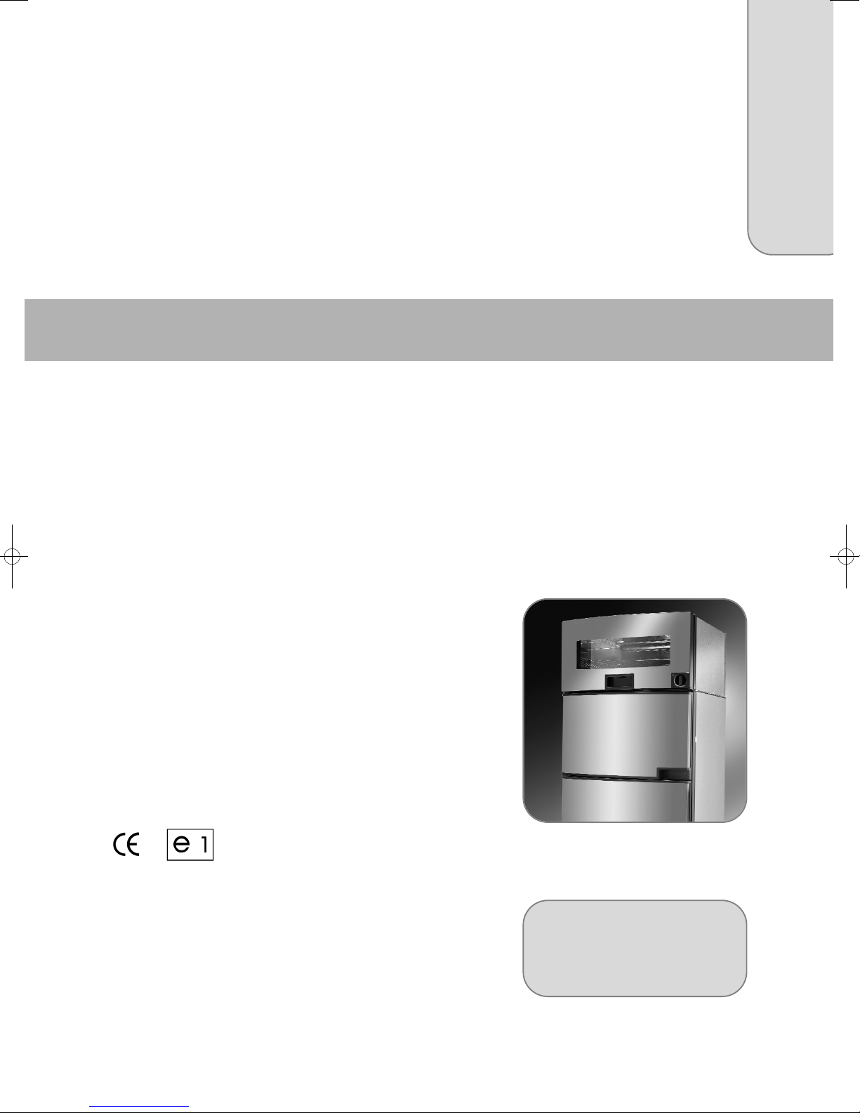
Absorber refrigerator with oven
Installation Manual
Nevera con extractor y horno
Instrucciones de montaje

RMDT 8501 RMDT 8505
RMDT 8551 RMDT 8555
MBA 07/2012
N 1
Installation Instructions
Absorption Refrigerator + Oven
for Recreation Vehicles
EN
English

2
© Dometic GmbH - 2012 - Subject to change
Dometic GmbH
In der Steinwiese 16
D-57074 Siegen
www.dometic.com

1.0 General . . . . . . . . . . . . . . . . . . . . . . . . . . . . . . . . . . . . . . . . . . . . . . 4
1.1 Introduction . . . . . . . . . . . . . . . . . . . . . . . . . . . . . . . . . . . . . . . . . . . . . . . . . . . . . . . . . . . . . . . . 4
1.2 Guide to these operating instructions . . . . . . . . . . . . . . . . . . . . . . . . . . . . . . . . . . . . . . . . . . . .4
1.3 Copyright protection . . . . . . . . . . . . . . . . . . . . . . . . . . . . . . . . . . . . . . . . . . . . . . . . . . . . . . . . . 4
1.4 Explanation of symbols used in this manual . . . . . . . . . . . . . . . . . . . . . . . . . . . . . . . . . . . . . . . 4
1.5 Warranty . . . . . . . . . . . . . . . . . . . . . . . . . . . . . . . . . . . . . . . . . . . . . . . . . . . . . . . . . . . . . . . . . . . 5
1.6 Limitation of liability . . . . . . . . . . . . . . . . . . . . . . . . . . . . . . . . . . . . . . . . . . . . . . . . . . . . . . . . . . 5
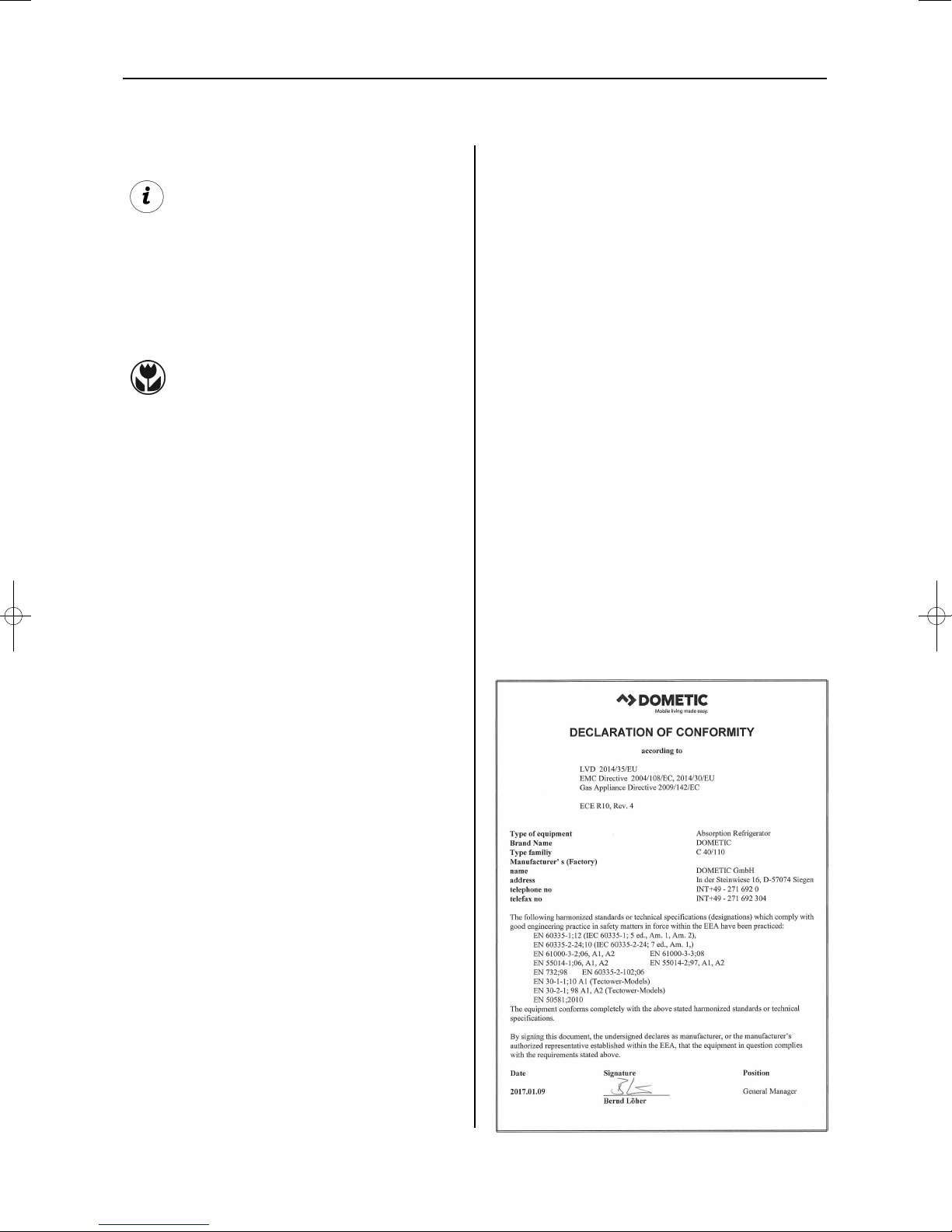
1.7 Declaration of conformity . . . . . . . . . . . . . . . . . . . . . . . . . . . . . . . . . . . . . . . . . . . . . . . . . . . . . . 5
2.0 Safety instructions . . . . . . . . . . . . . . . . . . . . . . . . . . . . . . . . . . . . . . 6
2.1 Application according to regulations . . . . . . . . . . . . . . . . . . . . . . . . . . . . . . . . . . . . . . . . . . . . .6
2.2 User's responsibility . . . . . . . . . . . . . . . . . . . . . . . . . . . . . . . . . . . . . . . . . . . . . . . . . . . . . . . . . . 6
2.3 Working upon and checking the refrigerator . . . . . . . . . . . . . . . . . . . . . . . . . . . . . . . . . . . . . . . 6
2.4 Operating the refrigerator with gas . . . . . . . . . . . . . . . . . . . . . . . . . . . . . . . . . . . . . . . . . . . . . . 6
3.0 Description of model . . . . . . . . . . . . . . . . . . . . . . . . . . . . . . . . . . . . 7
3.1 Model identification . . . . . . . . . . . . . . . . . . . . . . . . . . . . . . . . . . . . . . . . . . . . . . . . . . . . . . . . . . 7
3.2 Refrigerator rating plate . . . . . . . . . . . . . . . . . . . . . . . . . . . . . . . . . . . . . . . . . . . . . . . . . . . . . . . 7
3.3 Technical data . . . . . . . . . . . . . . . . . . . . . . . . . . . . . . . . . . . . . . . . . . . . . . . . . . . . . . . . . . . . . . 8
4.0 Installation instructions . . . . . . . . . . . . . . . . . . . . . . . . . . . . . . . . . . 9
4.1 Installation . . . . . . . . . . . . . . . . . . . . . . . . . . . . . . . . . . . . . . . . . . . . . . . . . . . . . . . . . . . . . . . . . 9
4.1.1 Side installation . . . . . . . . . . . . . . . . . . . . . . . . . . . . . . . . . . . . . . . . . . . . . . . . . . . . . . . . . . . . . . . . . . . . . . 9
4.1.2 Rear installation . . . . . . . . . . . . . . . . . . . . . . . . . . . . . . . . . . . . . . . . . . . . . . . . . . . . . . . . . . . . . . . . . . . . . 10
4.1.3 Draught-proof installation . . . . . . . . . . . . . . . . . . . . . . . . . . . . . . . . . . . . . . . . . . . . . . . . . . . . . . . . . . . . . . 10
4.2 Installation recess . . . . . . . . . . . . . . . . . . . . . . . . . . . . . . . . . . . . . . . . . . . . . . . . . . . . . . . . . . . . 12
4.2.1 Recess dimensions . . . . . . . . . . . . . . . . . . . . . . . . . . . . . . . . . . . . . . . . . . . . . . . . . . . . . . . . . . . . . . . . . . . 13
4.3 Ventilation . . . . . . . . . . . . . . . . . . . . . . . . . . . . . . . . . . . . . . . . . . . . . . . . . . . . . . . . . . . . . . . . . 14
4.3.1 Ventilation and air extraction of the refrigerator . . . . . . . . . . . . . . . . . . . . . . . . . . . . . . . . . . . . . . . . . . . . . 14
4.3.2 Oven ventilation and exhaust duct to vehicle's interior . . . . . . . . . . . . . . . . . . . . . . . . . . . . . . . . . . . . . . . 14
4.3.2.1 Ventilation to vehicle's interior . . . . . . . . . . . . . . . . . . . . . . . . . . . . . . . . . . . . . . . . . . . . . . . . . . . . . . . . . . 14
4.3.2.2 Ventilation via roof flue cowl . . . . . . . . . . . . . . . . . . . . . . . . . . . . . . . . . . . . . . . . . . . . . . . . . . . . . . . . . . . . 15
4.3.3 Height of ventilation . . . . . . . . . . . . . . . . . . . . . . . . . . . . . . . . . . . . . . . . . . . . . . . . . . . . . . . . . . . . . . . . . . 15
4.4 Installing the ventilation system . . . . . . . . . . . . . . . . . . . . . . . . . . . . . . . . . . . . . . . . . . . . . . . . . 16
4.4.1 Installation LS300 . . . . . . . . . . . . . . . . . . . . . . . . . . . . . . . . . . . . . . . . . . . . . . . . . . . . . . . . . . . . . . . . . . . . 16
4.4.2 Truma roof cowl AK3 installation . . . . . . . . . . . . . . . . . . . . . . . . . . . . . . . . . . . . . . . . . . . . . . . . . . . . . . . . 16
4.4.3 Installation of ventilation grill for ovens with interior ventilation . . . . . . . . . . . . . . . . . . . . . . . . . . . . . . . . . 17
4.5 Exhaust duct system (refrigerator) . . . . . . . . . . . . . . . . . . . . . . . . . . . . . . . . . . . . . . . . . . . . . . 17
4.6 Securing the refrigerator . . . . . . . . . . . . . . . . . . . . . . . . . . . . . . . . . . . . . . . . . . . . . . . . . . . . . . 17
4.7 Insert the decor panel . . . . . . . . . . . . . . . . . . . . . . . . . . . . . . . . . . . . . . . . . . . . . . . . . . . . . . . . 18
4.8 Gas installation . . . . . . . . . . . . . . . . . . . . . . . . . . . . . . . . . . . . . . . . . . . . . . . . . . . . . . . . . . . . . . 19
4.8.1 Connection pressure and gas categories . . . . . . . . . . . . . . . . . . . . . . . . . . . . . . . . . . . . . . . . . . . . . . . . . . 20
4.9 Electrical installation . . . . . . . . . . . . . . . . . . . . . . . . . . . . . . . . . . . . . . . . . . . . . . . . . . . . . . . . . . 20
4.9.1 Mains connection . . . . . . . . . . . . . . . . . . . . . . . . . . . . . . . . . . . . . . . . . . . . . . . . . . . . . . . . . . . . . . . . . . . . 20
4.9.2 12V (battery) connection . . . . . . . . . . . . . . . . . . . . . . . . . . . . . . . . . . . . . . . . . . . . . . . . . . . . . . . . . . . . . . . 21
4.9.3 Cable connections . . . . . . . . . . . . . . . . . . . . . . . . . . . . . . . . . . . . . . . . . . . . . . . . . . . . . . . . . . . . . . . . . . . 21
4 .9.4 D+ and solar connection . . . . . . . . . . . . . . . . . . . . . . . . . . . . . . . . . . . . . . . . . . . . . . . . . . . . . . . . . . . . . . 23
4.9.5 Wiring diagrams . . . . . . . . . . . . . . . . . . . . . . . . . . . . . . . . . . . . . . . . . . . . . . . . . . . . . . . . . . . . . . . . . . . . . 24
3
Table of Contents
4
General
1.0 General
On installation of the appliance, the technical
and administrative regulations of the country
in which the vehicle will first be used must be
adhered to. Otherwise the refrigerator must be
installed as described in these instructions. In
Europe, for example, gas appliances, cable
routing, installation of gas cylinders, as well as
approval and checking for leaks must comply
with EN 1949 for liquid gas systems in vehi-
cles.
1.1 Introduction
The information, texts and illustrations in these
instructions are copyright protected and are
subject to industrial property rights.
No part of these instructions may be reproduced, copied or utilised in any other way without written authorisation by Dometic GmbH,
Siegen, Germany.
1.3 Copyright protection
Before you start installing the refrigerator,
please read the installation instructions
carefully.
These instructions provide you with the necessary guidance for the proper installation of
your refrigerator. Observe in particular the
safety instructions. Observation of the
instructions and handling recommendations is
important for dealing with the refrigerator
safely and for protecting you from injury and
the refrigerator from damage. You must understand what you have read before you carry out
a task.
Keep these instructions in a safe place
close to the refrigerator so they may be
referred to at any time.
1.2 Guide to these installation
instructions
1.4 Explanation of symbols
used in this manual
Warning notices are identified by symbols. A
supplementary text gives you an explanation
of the degree of danger.
Observe these warning notices rigorously.
You will thus protect yourself and other
people from injury, and the appliance from
damage.
Warning notices
DANGER indicates an imminent hazardous
situation which, if not avoided, could result in
death or serious injury.
DANGER!
WARNING indicates a potentially hazardous
situation which, if not avoided, could result in
death or serious injury
WARNING!
CAUTION indicates a potentially hazardous
situation which, if not avoided, may result in
minor or moderate injury.
CAUTION!
CAUTION (used without the safety alert sym-
bol) indicates a potentially hazardous situation
which, if not avoided, may result in damage to
the appliance.
CAUTION!
5
General
All information and guidance in these operating instructions were prepared after taking
into consideration the applicable standards
and regulations as well as the current state of
the art. Dometic reserves the right to make
changes at any time which are deemed to be
in the interest of improving the product and
safety.
Dometic will assume no liability for damage in
the case of :
non-observation of the operating instructi-
ons
application not in accordance with the
regulations or provisions
use of non-original spare parts
modifications and interferences to the
appliance
effect of environmental influences, such as
- temperature fluctuations
- humidity
1.6 Limitation of liability
1.7 Declaration of conformity
Information
INFORMATION gives you supplementary and
useful guidance when dealing with your refrigerator.
Environmental Tips
ENVIRONMENTAL TIPS gives you useful gui-
dance for saving energy and disposal of the
appliance.
Warranty arrangements are in accordance
with EC Directive 44/1999/CE and the normal
conditions applicable for the country concerned. For warranty or other maintenance, please contact our customer services department.
Any damage due to improper use is not covered by the warranty. The warranty does not
cover any modifications to the appliance or
the use of non-original Dometic parts. The
warranty does not apply if the installation and
operating instructions are not adhered to and
no liability shall be entertained.
1.5 Warranty
6
This refrigerator / oven is designed for installation in recreation vehicles such as caravans or
motorhomes. The appliance has been typeapproval tested for this application in accordance with the EC Gas Directive.
The refrigerator is to be used solely for storing
foodstuffs and the oven for cooking dishes.
Any other use is considered improper and
incorrect creating hazardous conditions.
2.3 Working upon and checking
the refrigerator / oven
Work on gas equipment, exhaust system
and electrical facilities must be carried
out by authorised personnel only.
Substantial damage to property and/or
injury to persons can arise through unprofessional procedures.
WARNING!
Anyone operating the refrigerator must be
familiar with the safe handling and understand
the advice in these operating instructions.
2.2 User's responsibility
Flammable materials must be kept at a
safe distance to the oven.
The refrigerator must not be exposed to
rain.
CAUTION!
Safety instructions
2.0 Safety instructions
2.1 Application according to
regulations
Never use an unshielded flame to check
gas bearing parts and pipes for leakage!
There is a danger of fire or explosion..
DANGER!
Never open the absorber cooling unit! It is
under high pressure.
There is a danger of injury!
WARNING!
It is imperative that the operating pressure
corresponds to the data specified on the
rating plate of the appliance. Compare the
operating pressure of the rating plate with the
data specified on the pressure reducing valve
of the liquid gas cylinder.
2.4 Operating the appliance
with gas
7
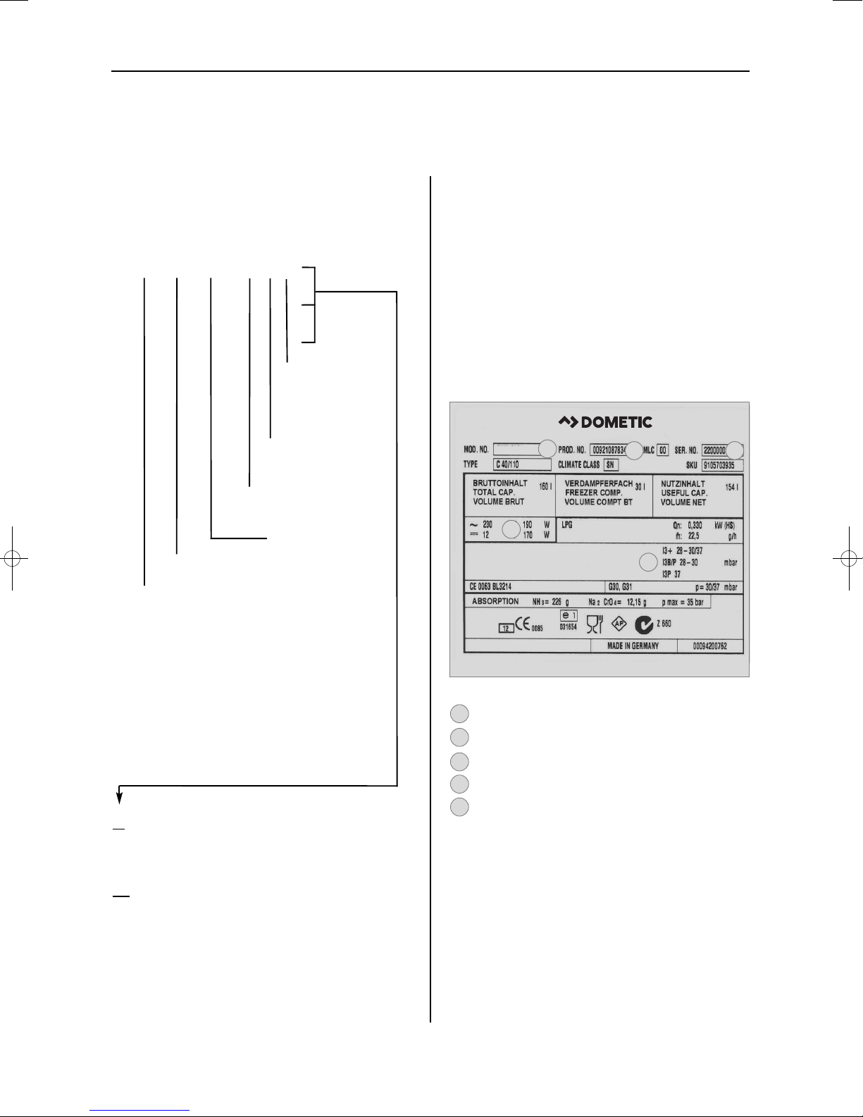
Fig. 1
RM
8 5 0 1
1
5
D
T
Refrigerator Mobile /
Mobile Absorption Refrigerator
Model range
with oven
5 = width 523mm
Depth:
0 = Standard
5 = + 55mm
6 = + 65mm
Double door refrigerator
Example :
1
manual energy selection, automatic ignition
(MES)
5
automatic and manual energy selection,
automatic ignition (AES)
Example
Model number
Product number
Serial number
Electrical rating details
Gas pressure
2
1
3
4
5
Description of model
3.0 Description of model
3.1 Model identification
The rating plate is to be found on the inside of
the refrigerator. It contains all important details
of the refrigerator. You can read off from this
the model identification, the product number
and the serial number. You will need these
details whenever you contact the customer
service centre or when ordering spare parts.
3.2 Refrigerator rating plate
2 3
4
5
RMDT 8501
1
8
Description of model
3.3 Technical data
Dometic refrigerators are equipped for a connection pressure of 30 mbar. For connection
to a 50 mbar gas system, use Truma VDR
50/30 medium pressure controller
Model Dimensions Gross capacity
Rating details
Consumption * Net Ignition
H x W x D (mm) with freezer mains/battery electricity/gas weight Piezo Automat
Depth incl. door compartment freezer cmpt. over 24hrs
Subject to technical changes.
*
Average consumption measured at an average ambient
temperature of 25°C in pursuance of ISO Standard.
RMDT 8501
RMDT 8505
RMDT 8551
RMDT 8555
*RMDT 85xx
with grill
oven only
1515*x523x567
1515*x523x567
1515*x523x622
1515*x523x622
1545x523x622
270x523x470
160 lit.
160 lit.
190 lit.
190 lit.
25 lit.
53.4 kg
53.4 kg
54.9 kg
54.9 kg
16.4 kg
30 lit.
30 lit.
35 lit.
35 lit.
190 W / 170 W
190 W / 170 W
190 W / 170 W
190 W / 170 W
•
•
•
•
•
ca.3,2 KWh / 380 g
ca.3,2 KWh / 380 g
ca.3,2 KWh / 380 g
ca.3,2 KWh / 380 g
Gas / h 70-100 g
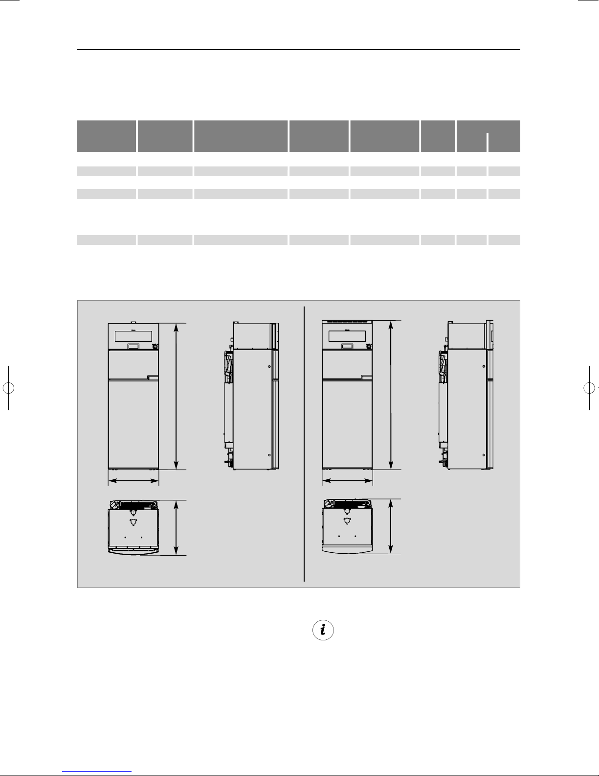
Fig. 2
RMDT 85xx / oven without grill
RMDT 85xx / oven with grill
H
B
T
H
B
T
9
Installation
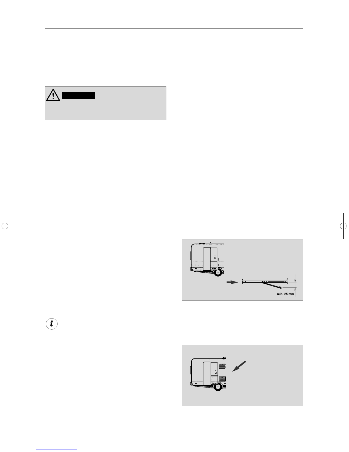
Fig. 3
Fig. 4
Air vent grille not
blocked! OK!
4.0 Installation instructions
The unit and the exhaust duct system must be
in principle installed so that it is accessible for
maintenance work, can be easily installed and
dismantled and removed from the vehicle without great effort.
Installation and connection of the appliance
must comply with the latest technical regulations, as follows:
The electrical installation must comply
with national and local regulations.
The gas installation must comply with
national and local regulations.
European Standards EN 1949
European Standards EN 60335-1,
EN 60335-2-24, EN 1648-1 , EN 1648-2
The appliance must be installed in such
a way that it is shielded from excessive
heat radiation.
Excessive heat impairs performance and raises the energy consumption of the refrigerator!
4.1 Installation
Deviations from these installation instructions without prior notification of Dometic
result in Dometic GmbH's warranty obligations becoming void!
The appliance may be installed by authorised personnel only!
WARNING!
(Fig. 4 )The air vent grilles offer an unobstructed dissipation of heat and exhaust gas even
when the door is opened.
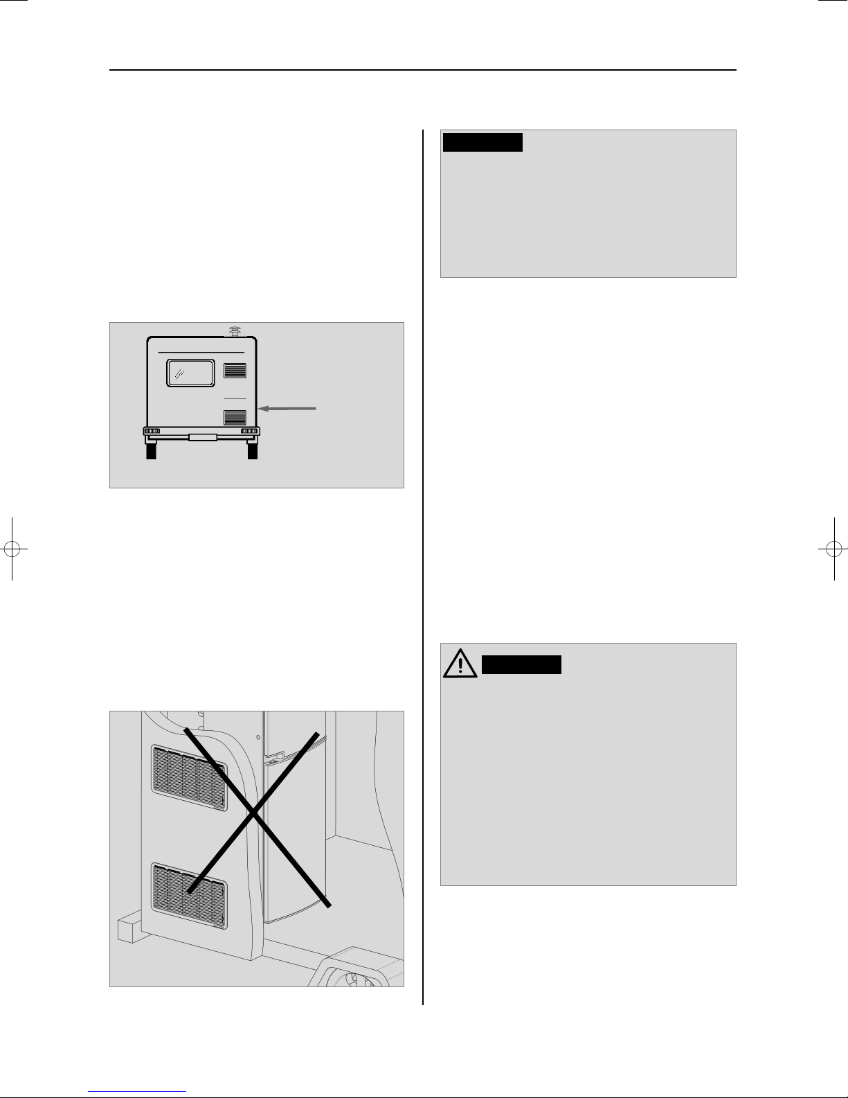
4.1.1 Side installation
If the appliance is installed on the same side of
the vehicle as the entrance door, it is desirable
that the door does not cover the refrigerator's
vents. (Fig. 3, Clearance door/ventilation grille
at least 25 mm). Otherwise ventilation could
be impaired which causes a loss in cooling
performance. Awnings are often placed at the
door side of a caravan. This complicates evacuation of combustion gases and heat through
the ventilation grilles (loss in cooling performance)!
(Fig. 3) The air vent grilles are blocked. There
must be a distance between the door and the
air vents of at least 25 mm!
If the door/grille distance is between 25 mm
and 45 mm, we recommend installing a
Dometic ventilation kit
(item no. 241 2985 -
00/0)
to achieve an optimal cooling perfor-
mance in high ambient temperatures.
10
Installation
Another unfavourable method of rear installation is to install the air intake and exhaust grilles (Fig. 6) at the side wall of the recreation
vehicle. The air-heat recirculation is very
restricted which means that heat exchangers
(condenser, absorber) cannot be adequately
cooled. The optional method of an additional
air vent grille installed in the floor also exhibits
an insufficient air flow duct.
Fig. 5
Air vent grille
not blocked!
OK!
4.1.2 Rear installation
Rear installation often causes an unfavourable
installation arrangement, as ideal ventilation
cannot always be assured (e.g. the lower ventilation grille is covered by the bumper or the
rear lights of the vehicle!). The maximum cooling performance of the aggregate is actually
not available.
The maximum cooling performance is not
available! Do not apply this installation
method, as it does not provide proper ventilation! Please refer to the description in
section 4.2.
CAUTION!
Fig. 6
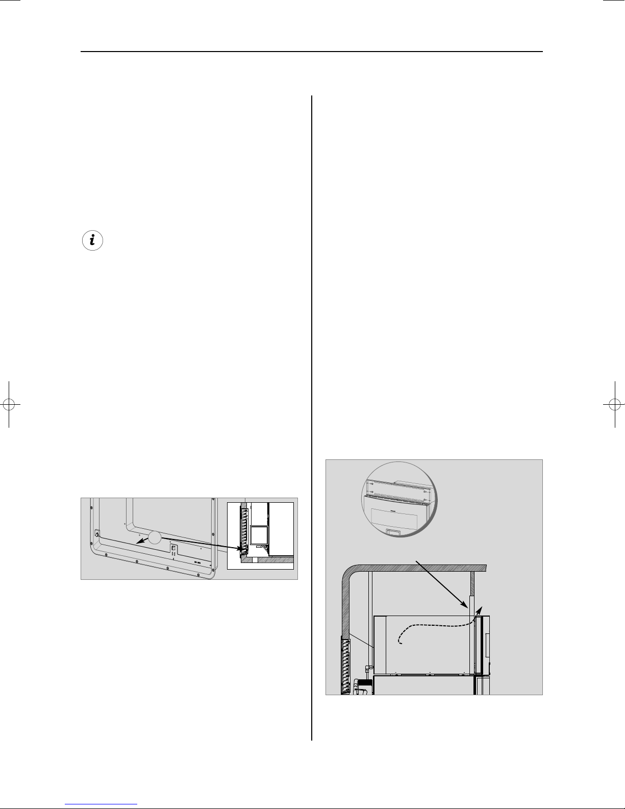
4.1.3 Draught-proof installation
Refrigerators in motorhomes, caravans or
other vehicles must be installed in a draughtproof manner (EN 1949). This means that the
combustion air for the burner is not taken from
the living space and that exhaust fumes are
prevented from entering the living space.
Adequate sealing between the back of the
refrigerator and the vehicle interior has to be
provided.
Dometic strongly recommend using a flexible
sealing for this purpose (temperature-resi-
stant up to 200 °C in the area of the oven),
in order to facilitate future removal or installation of the appliance during maintenance
By no means use durable sealing compounds, fitting foam or similar material to
realise draught-proof installation of the
refrigerator ! Do NOT use any easily
inflammable materials for sealing (in particular silicon sealing compound or similar).
Risk of fire! The device manufacturer's
product liability and warranty shall lapse if
such materials are used.
WARNING!
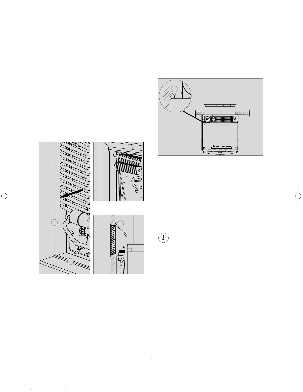
The lip seals (1) are installed at the bottom and
on each side in the installation recess (Fig. 7-
9). A heat deflector plate (2) is installed in the
installation recess above the refrigerator. Affix
this plate to the caravan wall, do NOT
attach to the refrigerator !
11
Installation
Deviations shall require the consent of the
manufacturer.
Fig. 8
Fig. 7
Fig. 9
Fig. 10
Attach the deflector plate so that the heated
air escapes through the top ventilation grill into
the open air and no heat build-up can be produced.
The refrigerator is later pushed into the installation recess from the front. Ensure that the
seals abut the case evenly.
This installation option facilitates the removal
and installation of the appliance for servicing.
If the cavity between the caravan wall and the
refrigerator is sealed so that fumes cannot
penetrate the living area it is possible to vent
the flue gas directly through the upper grille
without using the aluminium flue pipe. The
waste gases escape to the outside through
the upper grill of the ventilation. Do not use
any kind of aluminium flue pipe to lead the flue
gas out.
Fasten the sealing lips to a stop bar on the
rear side (1), e.g. by gluing.
1
1
2
1
2
Proposal 1
Proposal 2
12
Installation
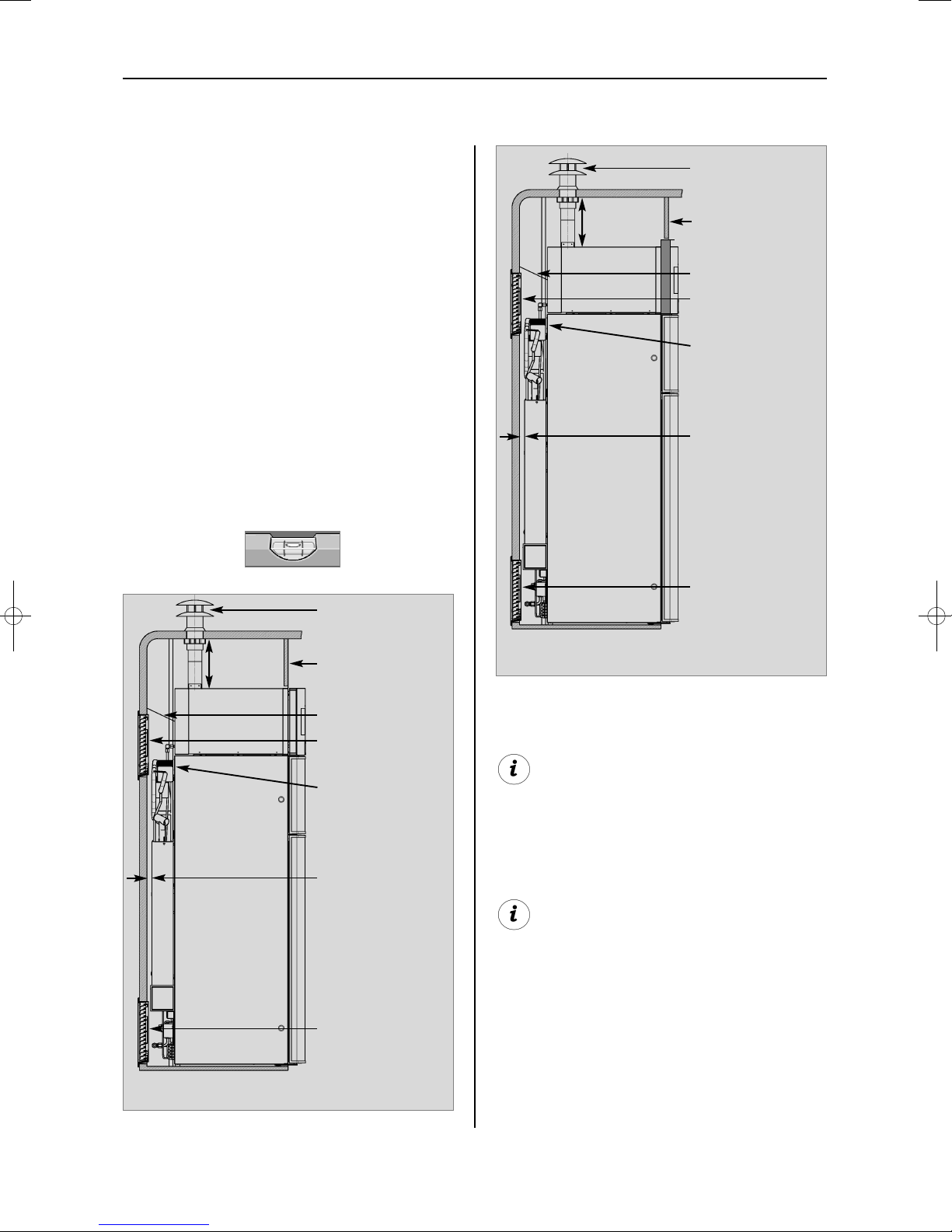
Fig. 11
Appliance without grillfunction
ventilation grille
LS300
condenser
cooling unit
gap between cooling unit and wall:
min. 15 mm
ventilation grille
LS300
Truma-flue outlet
AK3
removable screen /
grill
(for fixing of flue outlet)
heat reflector
170 mm min
The refrigerator must be installed draughtproof in a recess (also refer to Section "4.1.3").
The measurements of the recess are stated in
the table below. Push the appliance far
enough into the recess until the front edge of
the refrigerator casing is aligned with the front
of the recess. Allow a gap of 15-20 mm between the back wall of the recess and the refrigeration unit. The floor of the recess must be
level, allowing the appliance to be pushed
easily into its correct position. The floor must
be substantial enough to bear the weight of
the appliance. Install a removable screen / grill
above the oven (for fixing and removing of flue
outlet).
Ensure that the refrigerator is installed level
in the recess.
4.2 Installation recess
Fig. 12
Appliance with grillfunction
ventilation grille
LS300
condenser
cooling unit
gap between
cooling unit and
wall: min. 15 mm
ventilation grille
LS300
Truma-flue outlet
AK3
removable screen /
grill
(for fixing of flue outlet)
heat reflector
170 mm min
Observe instructions “4.3
Ventilation
” !
Correct mounting of the lower ventilation grille
facilitates access to the connections and
functional parts during maintenance.
13
Installation
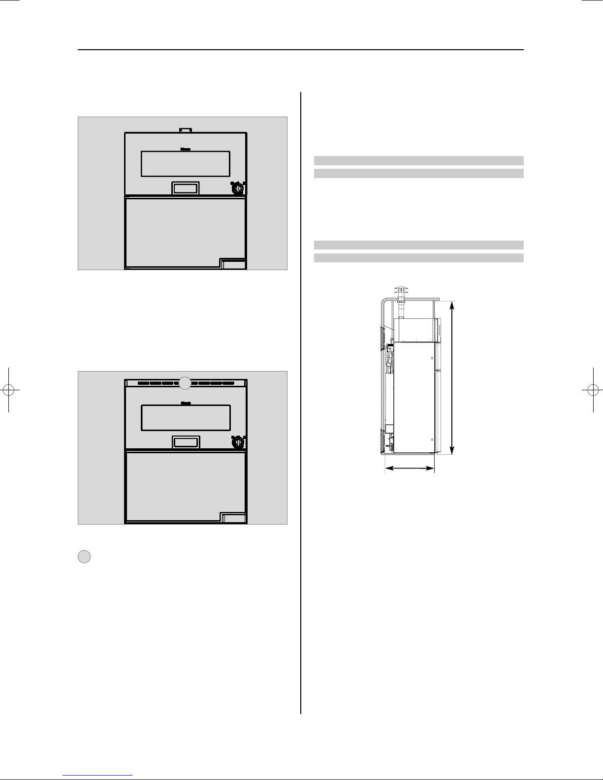
4.2.1 Recess dimensions
RMDT 8501, RMDT 8505
Model
Height Width Depth
1685 mm 527 mm 510 mm
1685 mm 527 mm 510 mm
RMDT 8551, RMDT 8555
Model
Height Width Depth
1685 mm 527 mm 565 mm
1685 mm 527 mm 565 mm
Distance of refrigerator unit to wall:
15 mm
Top edge of oven to ceiling: 170 mm
Ventilation grille
Minimum wall clearances
Appliance without grill function
Fig. 13
Appliance with grill function
Fig. 14
Fig. 15
H
T
1
1
14
Installation
Fig. 17
In the event of high ambient temperatures,
full performance of the cooling unit can
only be achieved by means of adequate
ventilation and extraction.
A correct installation of the refrigerator is
essential for its correct operation, as due to
physical reasons heat builds up at the back of
the appliance which must be allowed to escape into the open air.
If ventilation and exhaust duct into the vehicle
is intended, fresh air supply must not be
obstructed. The room in which the device is
installed must have one or several openings
allowing fresh air to enter (safety ventilation
according to EN 721). These openings must
have a total cross section of at least 100
cm². There must be one or several ventilation openings above the device with minimum cross sections of 150 cm². These have
to be checked and if necessary cleaned regularly. Roof and wall outlet openings can be
combined. Lower ventilation openings must
be no more than 100 mm above the inside
floor. The ventilation openings must by no
means be shut. Grilles and covers must be
kept clean and free of dust.
4.3.1 Ventilation and air extraction of
the refrigerator
4.3 Ventilation
4.3.2 Oven ventilation and exhaust
duct to vehicle's interior
4.3.2.1 Ventilation to vehicle's interior
(special equipment, model without
flue)
exhausts
Large panel with ventilation slots
(for ventilation to the vehicle’s interior)
Ventilation is provided for the unit by means of
two apertures (ventilation grilles) in the caravan wall. Fresh air enters at the bottom,
extracts the heat and exits through the upper
vent grille (chimney effect). The upper venti-
lation grille should be positioned as high as
possible above the cooling unit (Fig. 11).
Install the lower ventilation grille at floor
level of the recess floor (Fig. 16), allowing
unburnt gas (heavier than air) to escape directly into the open air. The gas burner must be
located above the edge (1) ..
Should this arrangement prove impossible,
a ventilation aperture must be introduced
by the manufacturer of the vehicle into the
recess floor in order to avoid the accumulation of unburnt gas on the floor.
The ventilation grilles must have an open
cross-section of at least 400 cm². This is
achieved by using the Dometic LS 300 absorber ventilation and air extraction system
which has been tested and approved for this
purpose.
Fig. 16
1
15
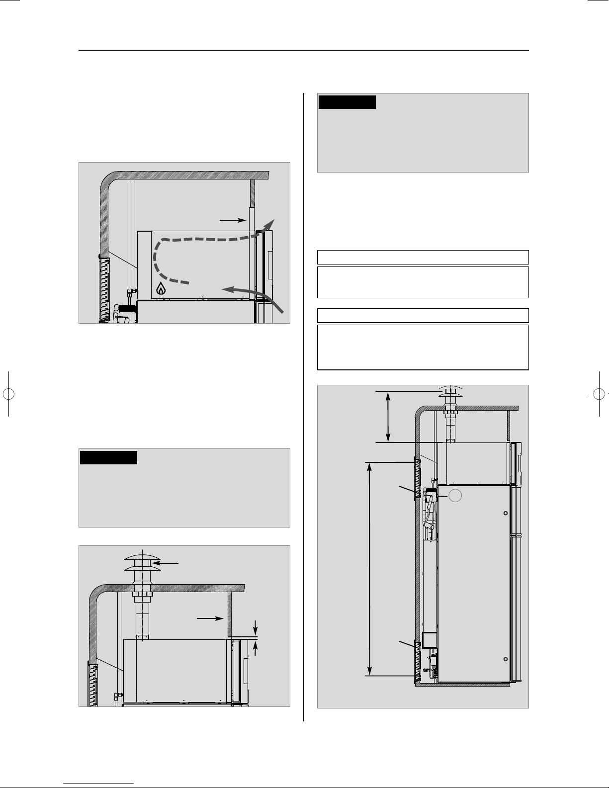
Installation
Special cowls for mounting on the roof are
used for the ventilation and exhaust gas duct.
Only use the cowl and pipes specified in
these instructions. These are tested and
approved for the application.
CAUTION!
There must not be any materials not designed for temperatures over 120 °C in the
vicinity of cowl and exhaust gas pipe.
CAUTION!
The hot exhaust air escapes from inside the
oven through the ventilation slots in the front
panel.
4.3.2.2 Ventilation via roof flue cowl
4.3.3 Ventilation heights
Fig. 20
Minimum ventilation height
LS300
LS300
H
K
Minimum ventilation height H
B
Oven :
Truma roof flue cowl AK3 250 mm
Minimum ventilation height H
K
Refrigerator :
upper ventilation grille LS 300
lower ventilation grille LS 300 > 1400 mm
H
B
1
Details on oven ventilation to vehicle's
interior
Fig. 18
Fig. 19
Truma roof flue
cowl AK3
panel with ventilation slots
gas burner
exhausts
incoming air
removable
screen
10 mm
 Loading...